manual for radio-amateurs
TRANSCRIPT

1
Manual for
Radio-Amateurs
for receiving and decoding telemetry
data from the PEGASUS satellite
revised version by Pablo Cañamares
ham operators manual 11.docx
MT-OE1MTS, PCR: 12. 08. 2021 Version 1.1

2
DOCUMENT CHANGE RECORD Project: PEGASUS - Communication Change Status Log: V0.5, 22. 5. 2017, MT Document created from previous documents V1.0, 24. 5. 2017, MT CRC, FEC, description added, O-Beacon explained V1.1, 12. 8. 2021, PCR Q numbering system explained, cosmetic changes.

3
Abbreviations ADCS Attitude Control System AID Address Identifier CALL Call Sign (Ham Radio Call Sign) of the satellite CRC Cyclic Redundancy Checksum E-Beacon EPS-Beacon EPS Electrical Power System FEC Forward Error Correction (RS Code) GPS Global Positioning System GS Ground Station IARU International Amateur Radio Union ILEOP Initial Launch and Early Orbit Phase LEOP Launch and Early Orbit Phase MCC Mission Control Center OBC Onboard Computer O-Beacon OBC-Beacon PCB Printed Circuit Board PID Protocol Identifier RBF Raw Binary File RS Reed Solomon RSSI Received Signal Strength Indication RTC Real Time Clock S-Beacon STACIE-Beacon SDC Space Data Center Side-P Side Panels STG Space Tech Group STACIE Space Telemetry And Command InterfacE TRX Transceive, Transceiver TT-64 Thomas Turetschek 64 byte protocol TX Transmit, Transmitter WOD Whole Orbit Data µPPT microprocessor

4
1 Radio Engineering Parameter of Pegasus The Pegasus satellite is a 2U CubeSat with 2 redundant TRX modules on one PCB. Each of the two communications modules (called STACIE) uses one of the two independent dipole antennas built at a 90º angle of each other. STACIE draws power from two independent buses to the satellite main power. The end result is a redundant and reliable communications system.
Downlink Frequency 436,670 MHz
TX power max 30dBm, 1W
Modulation GFSK
Polarisation Linear
Protocol TT-64

5
2 TT-64 Protocol The TT-64 protocol regulates the data transfer between the satellite and the GS in both directions (air interface). The TT-64 protocol supports the time division multiplex method (semi duplex communication). A complete data packet consists of a 70 bytes string. The first 6 bytes are created automatically for synchronizing and receiver tuning. The remaining 64 bytes are data bytes, divided into 46 data bytes and 18bytes used for CRC and FEC.
2.1 Down-Link From the 46 bytes of data the first byte must be the PID and the next 6 bytes the CALL.
The CALL is the official call sign of the satellite.

6
2.2 PID Regulation The PID indicates which subsystem is sending the data packet and the type of packet called beacon). Thanks to the PID it is possible to distinguish between the different beacons and route them to the appropriate decoding operations.
Assigned PIDs Content hex binary S Beacon 0xC0 11000000 E Beacon 0xC1 11000001 O Beacon 1/2 0x53 01010011 O Beacon 2/2 0x56 01010110
2.3 CALL
The assigned call sign of the satellite PEGASUS is ON03AT. The call sign is encoded using the ASCII standard. Symbol O N 0 3 A T Hex 0x4F 0x4E 0x30 0x33 0x41 0x54 Binary 01001111 01001110 00110000 00110011 01000001 01010100
2.4 FEC and CRC The FEC and CRC are not necessary for receiving and decoding the beacons. Their function is to provide error detection and error correction in the raw data. CRC The Cyclic Redundancy Checksum (CRC) is a standard CRC16 Checksum. FEC The Forward Error Correction (FEC) is a Reed Solomon (RS) code with the following Specifications: RS (n=64, k=48) Generator-polynomial-coefficients:
79 44 81 100 49 183 56 17 232 187 126 104 31 103 52 118 With this technique it is possible to repair eight errors per 64bit packet.
7
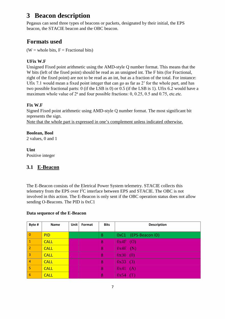
3 Beacon description Pegasus can send three types of beacons or packets, designated by their initial, the EPS beacon, the STACIE beacon and the OBC beacon.
Formats used (W = whole bits, F = Fractional bits) UFix W.F Unsigned Fixed point arithmetic using the AMD-style Q number format. This means that the W bits (left of the fixed point) should be read as an unsigned int. The F bits (for Fractional, right of the fixed point) are not to be read as an int, but as a fraction of the total. For instance: Ufix 7.1 would mean a fixed point integer that can go as far as 2⁷ for the whole part, and has two possible fractional parts: 0 (if the LSB is 0) or 0.5 (if the LSB is 1). Ufix 6.2 would have a maximum whole value of 2⁶ and four possible fractions: 0, 0.25, 0.5 and 0.75, etc.etc. Fix W.F Signed Fixed point arithmetic using AMD-style Q number format. The most significant bit represents the sign. Note that the whole part is expressed in one’s complement unless indicated otherwise. Boolean, Bool 2 values, 0 and 1 Uint Positive integer 3.1 E-Beacon
The E-Beacon consists of the Eletrical Power System telemetry. STACIE collects this telemetry from the EPS over I2C interface between EPS and STACIE. The OBC is not involved in this action. The E-Beacon is only sent if the OBC operation status does not allow sending O-Beacons. The PID is 0xC1 Data sequence of the E-Beacon
Byte # Name Unit Format Bits Description
0 PID 8 0xC1 (EPS-Beacon ID) 1 CALL 8 0x4F (O) 2 CALL 8 0x4E (N) 3 CALL 8 0x30 (0) 4 CALL 8 0x33 (3) 5 CALL 8 0x41 (A) 6 CALL 8 0x54 (T)

8
7 I_PV2_5V A Fix 3.4 8 Current through FET3-2 between PV2-bus and 5V converter
8 I_PV1_5V A Fix 3.4 8 Current through FET3-1 between PV1-bus and 5V converter
9 V_PV2 V UFix 3.5 8 Voltage at PV2-bus, Solarbus 2
10 V_5V_IN V UFix 3.5 8 Voltage at the input of the 5V converter measured at FET3-1
11 I_PV1_3V3 A Fix 3.4 8 Current through FET5-1 between PV1-bus and 3V3 converter
12 I_PV2_3V3 A Fix 3.4 8 Current through FET5-2 between PV2-bus and 3V3 converter
13 V_PV1 V UFix 3.5 8 Voltage at PV1-bus, Solarbus 1
14 V_3V3_IN V UFix 3.5 8 Voltage at the input of the 3V3 converter measured at FET52
15 Temp_BAT1SW °C Fix 7.0 8 Temp near BAT1 switches
16 Temp_5V °C Fix 7.0 8 Temp near 5V converter
17 I_PV1_HV A Fix 3.4 8 Current through FET4-1 between PV1-bus and HV supply
18 I_PV2_HV A Fix 3.4 8 Current through FET4-2 between PV2-bus and HV supply
19 V_3V3_OUT V UFix 3.5 8 Voltage at the output of the 3V3 converter
20 V_HV V UFix 3.5 8 Voltage at the output of the HV supply to the PPTs measured at FET4-2
21 I_PV2_BAT1 A Fix 3.4 8 Current through FET1-2 between PV2-bus and battery 1
22 I_PV1_BAT1 A Fix 3.4 8 Current through FET1-1 between PV1-bus and battery 1
23 V_5V_OUT V UFix 3.5 8 Voltage at the output of the 5V converter
24 V_BAT1 V UFix 3.5 8 Voltage of the battery 1
25 I_PV2_BAT2 A Fix 3.4 8 Current through FET2-2 between PV2-bus and battery 2
26 I_PV1_BAT2 A Fix 3.4 8 Current through FET2-1 between PV1-bus and battery 2
27 Version of EPS 8 Versions Number of EPS
28 STACIE 0/1 boolean LSB E-Beacon send by STACIE 0/1 (A/C)
29 V_BAT2 V UFix 3.5 8 Voltage of the battery 2
30 Temp_BAT1 °C Fix 7.0 8 Temp of BAT1 on the battery holder
31 Temp_BAT2 °C Fix 7.0 8 Temp of BAT2 on the battery holder
32 Status 1 - boolean 8 B7 (MSB): 3V3-1 on, B6: 3V3-2 on, B5: 3V3-3 on, B4: 3V3Backup on, B3: 5V-1 on, B2: 5V-2 on, B1: 5V-3 on, B0 (LSB): 5V-4 on.
33 Status 2 - boolean 8 B7 (MSB): Low Power Warning (EPS will enter in Power Down Mode soon after this warning), B6: Bat1 connected to PV1, B5: Bat2 connected to PV2, B4: 3V3 on, B3: 5V on, B2-B0 (LSBs): 000 Debug Mode, 001 Boot Mode, 010 Flight Mode, 011 Power Down Mode, 100 Safe Mode.

9
34 Status 3 - boolean 8 B7 (MSB): 3V3 Burst Mode on, B6: 5V Burst Mode on, B5: Bat1 connected to PV2, B4: Bat2 connected to PV1, B3: Temperature warning flag, B2: CC1 connection okay flag, B1: CC2 connection okay flag, B0 (LSB): RBF
35 Status 4 EPS 8
36 Beacon Count S
Uint 8 Beacon Count of STACIE Beacons
37 Reboot_MC - UFix 8.0 8 Number of reboots since last change of the RBF of the main controller
38 Reboot_CC1 - UFix 8.0 8 Number of reboots since last change of the RBF of the first communication controller
39 Reboot_CC2 - UFix 8.0 8 Number of reboots since RBF of the second communication controller
40 Vcc_CC1 V UFix 3.5 8 Supply voltage of CC1
41 Temp_CC1 °C Fix 7.0 8 Temperature of the internal sensor of CC1
42 Vcc_CC2 V UFix 3.5 8 Supply voltage of CC
43 Temp_CC2 °C Fix 7.0 8 Temperature of the internal sensor of CC2
44 Status_CC1 - boolean 8 B7 (MSB)-B6: CC Mode: 00 Boot Mode, 01 Flight Mode, 10 Safe Mode, 11 CC1 unavailable, B5: mcTimeoutFlag, B4: RBF (CC1 only), B3: EN_I2C, B2: Bat1 connected to PV1, B1: Bat2 connected to PV2, B0 (LSB): 3V3-Backup on
45 Status_CC2 - boolean 8 B7 (MSB)-B6: CC Mode: 00 Boot Mode, 01 Flight Mode, 10 Safe Mode, 11 CC2 unavailable, B5: mcTimeoutFlag, B4: TBD B3: EN_I2C, B2: Bat1 connected to PV1, B1: TBD, B0 (LSB): 3V3-Backup on
CRC 16
FEC 128

10
3.2 S-Beacon
The S-Beacon consists of the STACIE telemetry. The telemetry is generated and stored in the communication subsystem STACIE and immediately available by internal storage. The OBC is not involved in this action. The S-Beacon is only sent if the OBC operation status does not allow sending O-Beacons. If O-Beacons or other packets from the OBC are sent, an S-Beacon is sent after around every 30th packet sent by the OBC. The PID is 0xC0 Data Packet
Data sequence of the S-Beacon Byte # Name Byte Notes Unit Description length 0 PID 1 0xC0 Stacie Beacon ID
1 Call Sign 6 0x4F O
2 Call Sign 0x4E N
3 Call Sign 0x30 0
4 Call Sign 0x33 3
5 Call Sign 0x41 A
6 Call Sign 0x54 T
7 USP 2 Low Byte Supply Voltage of Stacie in mV
8 High Byte
9 TRX Temp 1 Temperature of Stacie‘s Communicatio
10 Idle RSSI 1 -132dBm + (value/2) Ufix 7.1
Received Signal Strength Indication, without TRX
11 RX RSSI 1 -132dBm + (value/2) Ufix 7.1
Received Signal Strength Indication, during RX
12 Antenna Deployment 1 Boolean
0= not deployed, 1=deployed For Antenna 1, 2, 3, 4
13 Stacie OP 1
Operational Mode: 0=Normal, 2=Sleep, 3=Beacon, 4=Deployment, 8=Shutdown
14 T-Comp On/Off 1 Boolean Temperature Compensation On/Off (1=on, 0=off)

11
15 Reset Counter 2 Low Byte Reset after last mP-Flash
16 High Byte
17 Uplink Error 1 Uplink Error rate
18
OBC Sent Packet counter between S-Beacons 1
Packets send between 2 Stacie Beacons
19 Beacon Interval 2 Low Byte Stacie Beacon interval in seconds
20 High Byte
21 Reserved 8
22-28 Reserved
29 SID 1 boolean 0=STACIE A, 1=STACIE C
30 TxSelReason 1 Weight why Stacie is Master
31 reason remote 1 Weight of partner-stacie, 0=No answer
32 sTime 4 Byte 0 Stacie Up-Time in mseconds since last reset
33 Byte 1
34 Byte 2
35 Byte 3
36 Reserved 1
37 BeaconCount 1 Number of Beacons send from Stacie
38-45 Reserved
CRC 2
FEC 16

12
3.3 O-Beacon
The O-Beacon consists of OBC, STACIE, EPS, µPPT, GPS and ADCS telemetry. The OBC is collects and stores the telemetry of the mentioned subsystems. The OBC is sends the collected data in two packets to STACIE, which is adds the CRC and the FEC before transmission Each packet has its own PID, so it can be decrypted even if the other is lost. The PID of the first packet is 0x53 and of the second packet, 0x56. Telemetry marked with WOD (Whole Orbit Data) in the comments field is telemetry, which is required by QB50. The WOD telemetry is also displayed in the public area of the MCC. The table contains information about what information comes from what subsystem. O-Beacon nº 1 consists of the EPS telemetry and some telemetry from STACIE and the OBC. O-Beacon nº 2 consist of the GPS data, ADCS and Side Panels data and a sizeable amount of OBC status parameters, expressed in boolean. Data Packets
OBC BEACON 1/2
# Name Unit Format Bit Comments Sub-system
0 PID 8 0x53(OBC-Beacon 1 ID)
1 CALL 8 0x4F (O) 2 CALL 8 0x4E (N) 3 CALL 8 0x30 (0) 4 CALL 8 0x33 (3) 5 CALL 8 0x41 (A) 6 CALL 8 0x54 (T) 7 V_PV1 V UFix 3.5 8 WOD EPS 8 V_PV2 V UFix 3.5 8 WOD EPS 9 V_5V_IN V UFix 3.5 8 EPS 10 V_3V3_IN V UFix 3.5 8 EPS 11 V_5V_OUT V UFix 3.5 8 WOD EPS 12 V_3V3_OUT V UFix 3.5 8 WOD EPS 13 I_PV1_5V A Fix 3.4 8 WOD as I_5V EPS 14 I_PV2_5V A Fix 3.4 8 WOD as I_5V EPS 15 I_PV1_3V3 A Fix 3.4 8 WOD as I_3V3 EPS

13
16 I_PV2_3V3 A Fix 3.4 8 WOD as I_3V3 EPS 17 Temp_BAT1SW °C Fix 7.0 8 WOD as
Temp_EPS EPS
18 Temp_5V °C Fix 7.0 8 WOD as Temp_EPS
EPS
19 V_HV V UFix 3.5 8 EPS 20 I_PV1_BAT1 A Fix 3.4 8 WOD as I_Bat1 EPS 21 I_PV2_BAT1 A Fix 3.4 8 WOD as I_Bat1 EPS 22 I_PV1_BAT2 A Fix 3.4 8 WOD as I_Bat2 EPS 23 I_PV2_BAT2 A Fix 3.4 8 WOD as I_Bat2 EPS 24 V_BAT1 V UFix 3.5 8 WOD EPS 25 V_BAT2 V UFix 3.5 8 WOD EPS 26 Vcc_CC2 V UFix 3.5 8 EPS 27 Vcc_CC1 V UFix 3.5 8 EPS 28 Temp_BAT1 °C Fix 7.0 8 WOD (as Temp
Bat) EPS
29 Temp_BAT2 °C Fix 7.0 8 WOD (as Temp Bat)
EPS
30 Status 1 - boolean 8 EPS 31 Status 2 - boolean 8 EPS 32 Status 3 - boolean 8 EPS 33 Status_CC1 - boolean 8 EPS 34 Status_CC2 - boolean 8 EPS 35 Reboot_MC - boolean 8 EPS 36 Reboot_CC1 - boolean 8 EPS 37 Reboot_CC2 - boolean 8 EPS
38 Temp A °C 8
WOD (Temp TT&C), STACIE A temperature STACIE
39 Temp C °C 8
WOD (Temp TT&C), STACIE C temperature STACIE
40 RSSI A (X+) -132dBm + (value/2) 8
Receive Signal Strength Indicator of STACIE A STACIE
41 RSSI C (X-) -132dBm + (value/2) 8
Receive Signal Strength Indicator of STACIE C STACIE
42 STACIE Mode A 4
MSB operating mode of STACIE A STACIE
42 STACIE Mode C 4
LSB operating mode of STACIE C STACIE
43 state machine 8
WOD (OBC Status) Bit 7: SU Script active (1 if science script is running or waiting for next OBC

14
time table entry/next day) Bit 6: SU Powered (1 if Science Unit is active and powered on ) Bit 5: ADCS enabled (1 if enabled 0 if disabled) Bit 4: n.u. Bit3..0:”OBC Mission State” (0 – Standby)
44 CmdCnt 8 OBC Mission Counter OBC
45 CmdCnt 8 OBC Mission Counter OBC
CRC 16
FEC 128

15
OBC BEACON 2/2
# Name Unit Format Bits Comment Sub-
system 0 PID 8 0x56 (OBC-Beacon 2
ID)
1 CALL 8 0x4F (O)
2 CALL 8 0x4E (N)
3 CALL 8 0x30 (0)
4 CALL 8 0x33 (3)
5 CALL 8 0x41 (A)
6 CALL 8 0x54 (T)
7 Date ddmmyy 14 Date of GPS data (when fix success, RTC if no fix since last OBC reset)
GPS
Time hhmmss 17 Time of GPS data (when fix success, RTC if no fix since last OBC reset)
GPS
Fix Bool 1 GPS Number of Satellites seen Uint? 4 GPS
Lattitude 9000.0000N 28
Bits: 1 sign, 7 deg, 7 mins int ,13 mins fract GPS
Longitude 18000.0000W 29
Bits: 1 sign, 8 deg, 7 mins int ,13 mins fract GPS
Altitude 20 in m GPS
7 Fill bits GPS
22 ADCS Status 8 ADCS
23 ADCS Angle Dev 8 ADCS

16
OBC Status states
Byte 24 Bit #
24 Crystal oscillator in use Bool 0 1… Crystal oscillator operational
OBC
24 power_source Bool 1 0… 3.3V_SPA, 1… V_Backup OBC
24 last_reset_source1 Bool 2 Two bits showing the last reset source OBC
24 last_reset_source2 Bool 3
POR: 0b00, EXTR: 0b01, WDTR: 0b10, BODR: 0b11 OBC
24 eps_cc_used Bool 4 0…CC1, 1… CC2 OBC
24 obc_power saving mode Bool 5 OBC controller is in power saving mode mode OBC
24 obc_3v3_spa_enabled Bool 6 This is the standard power supply rail of the OBC! OBC
24 task_sensors_running Bool 7 Main sensor task is running OBC
Byte 25 Bit #
25 task_maintenance_ running Bool 0
Mandatory maintenance task is running OBC
25 statemachine_initialized Bool 1 Statemachine task is initialized
OBC
25 rtc_synchronized Bool 2 RTC time and date is up to date
OBC
25 i2c0_initialized Bool 3 I2C interface is operational OBC
25 i2c1_initialized Bool 4 I2C interface is operational OBC
25 i2c2_initialized Bool 5 I2C interface is operational OBC
25 ssp0_initialized Bool 6 SSP interface is operational OBC
25 ssp1_initialized Bool 7 SSP interface is operational OBC

17
Byte 26 Bit #
26 supply_switches_initialized Bool 0 GPIOs for power supply switching are initialized OBC
26 i2c_switches_initialized Bool 1 I2C switches are initialized OBC
26 rtc_initialized Bool 2 Real time clock is operational
OBC
26 adc_initialized Bool 3 Adc is operational OBC
26 uart_gps_initialized Bool 4 UART interface operational OBC
26 uart_ttc2_initialized Bool 5 UART interface operational
OBC
26 uart_mnlp_initialized Bool 6 UART interface operational
OBC
26 uart_ttc1_initialized Bool 7 UART interface operational
OBC
Byte 27 Bit #
27 timer0_initialized Bool 0 Timer initialized OBC
27 watchdog_initialized Bool 1 Watchdog initialized OBC
27 timer1_initialized Bool 2 Timer initialized OBC
27 eps_cc1_operational Bool 3 Eps CC1 communication ok OBC
27 eps_cc2_operational Bool 4 Eps CC2 communication ok OBC
27 eeprom1_initialized Bool 5 Eeprom initialized OBC
27 eeprom2_initialized Bool 6 Eeprom initialized OBC
27 eeprom3_initialized Bool 7 Eeprom initialized OBC
Byte 28 Bit #
28 mag_bp_initialized Bool 0 Mag BP communication ok OBC
28 mag_bp_boom_initialized Bool 1 Magnetometer on boom initialized
OBC
28 gyro1_initialized Bool 2 Low rate gyro initialized OBC
28 gyro2_initialized Bool 3 Low rate gyro initialized OBC
28 msp_initialized Bool 4 Msp JTAG programmer initialized OBC
28 onboard_mag_initialized Bool 5 Onboard magnetometer operational OBC
28 onboard_tmp100_initialized Bool 6 Onboard TMP100 temp sensor operational OBC
28 mpu_initialized Bool 7 Mpu gyro initialized OBC

18
Byte 29 Bit #
29 flash1_initialized Bool 0 External flash storage initialized
OBC 29 flash2_initialized Bool 1 External flash storage initialized OBC
29 spa_initialized Bool 2 Side panel operational OBC 29 spb_initialized Bool 3 Side panel operational OBC 29 spc_initialized Bool 4 Side panel operational OBC
29 spd_initialized Bool 5 Side panel operational OBC 29 sa_initialized Bool 6 Science adapter operational OBC
29 bp_initialized Bool 7 Bottom panel operational OBC
Byte 30 Bit # 30 gps_initialized Bool 0 Gps initialized OBC
30 ttc1_initialized Bool 1 Ttc initialized OBC
30 ttc2_initialized Bool 2 Ttc initialized OBC
30 science_module_initialized Bool 3 Science MODULE comms. operational OBC
30 spa_vcc_on Bool 4 SPA Power supply enabled OBC 30 spb_vcc_on Bool 5 SPB Power supply enabled OBC 30 spc_vcc_on Bool 6 SPC Power supply enabled OBC
30 spd_vcc_on Bool 7 SPD Power supply enabled OBC
Byte 31 Bit #
31 bp1_vcc_on Bool 0 Power supply of Bottom panel 1 enabled OBC
31 bp2_vcc_on Bool 1 Power supply of Bottom panel 2 (boom) enabled
OBC
31 sa_vcc_on Bool 2 Power supply science adapter enabled
OBC
31 i2c_sw_a_on Bool 3 I2C of SPA is connected OBC
31 i2c_sw_b_on Bool 4 I2C of SPb is connected OBC 31 i2c_sw_c_on Bool 5 I2C of SPC is connected OBC 31 i2c_sw_d_on Bool 6 I2C of SPD is connected OBC
31 onboard_mag_powersafe Bool 7 Onboard magnetometer is in power saving mode OBC

19
Byte 32 Bit #
32 gyro_powesafe Bool 0 Low rate gyro is in power saving mode OBC
32 mpu_powersafe Bool 1 MPU is in power saving mode OBC
32 tmp100_powersafe Bool 2 TMP100 is in power saving mode OBC
32 mag_bp_power saving mode Bool 3
Magnetometer on bottom panel is in power saving mode
OBC
32 mag_bp_boom_power saving mode Bool 4
Magnetometer on boom is in power saving mode OBC
32 mnlp_5v_enabled: Bool 5 5V power supply for MNLP is enabled OBC
32 rtc_oscillator_error Bool 6 oscillator of RTC not operational OBC 32 eeprom_page_cycle_overflow Bool 7 At least one EEPROM page has >
1e6 cycles OBC
Byte 33 Bit #
33 ssp0_frequent_errors Bool 1 SSP interface produces errors frequently OBC
33 ssp1_frequent_errors Bool 1 SSP interface produces errors frequently OBC
33 i2c0_frequent_errors Bool 1 I2C interface produces errors frequently OBC
33 i2c1_frequent_errors Bool 1 I2C interface produces errors frequently OBC
33 i2c2_frequent_errors Bool 1 I2C interface produces errors frequently OBC
33 timer0_running Bool 1 Timer is operational and running
OBC
33 timer1_running Bool 1 Timer is operational and running
OBC
33 default_config_used Bool 1 Default configuration of OBC is used OBC

20
# Name Format Bits Comment Sub-system 34 error_code; uint8_t 8 Hardware error code OBC
35 error_code_before_reset uint8_t 8 Last hardware error code before reset OBC
36 resets counter uint32_t 8 Reset counter since mission start OBC
40 Temp SP X- 8 temperature sidepanel X-
SideP
41 Temp SP X+ 8 temperature sidepanel X+ SideP
42 Temp SP Y- 8 temperature sidepanel Y-
SideP
43 Temp SP Y+ 8 temperature sidepanel Y+ SideP
44 Script Slots 8
bit 7: Cmd Scrip Slot 1(8) loaded bits 6..0: Science Script Slots 7,6,5,4,3,2,1 loaded OBC
45 Script Slot 8
bits 7..4: n.u. bits 3..0: Cmd Script Slot 5(12),4(11), 3(10),2(9) loaded
OBC CRC 16
FEC 128 OBC Beacon 1/2 CmdCnt: Counter of received and processed commands, even if they had no impact. OBC Beacon 2/2 GPS Time and Date: as long as the GPS has no fix, the RTC Date and -Time of the OBC since the last reset is recorded in these telemetry sections. (Epoche Time 1.1.2015) If the GPS is reporting a fix, the RTC is UTC.