radio amateurs hand book
TRANSCRIPT

8/3/2019 Radio Amateurs Hand Book
http://slidepdf.com/reader/full/radio-amateurs-hand-book 1/201
The Project Gutenberg eBook of The RadioAmateur's Hand Book, by A. Frederick CollinsCopyright laws are changing all over the world. Be sure to check thecopyright laws for your country before downloading or redistributing
this or any other Project Gutenberg eBook.
This header should be the first thing seen when viewing this ProjectGutenberg file. Please do not remove it. Do not change or edit theheader without written permission.
Please read the "legal small print," and other information about theeBook and Project Gutenberg at the bottom of this file. Included isimportant information about your specific rights and restrictions inhow the file may be used. You can also find out about how to make adonation to Project Gutenberg, and how to get involved.
**Welcome To The World of Free Plain Vanilla Electronic Texts**
**eBooks Readable By Both Humans and By Computers, Since 1971**
*****These eBooks Were Prepared By Thousands of Volunteers!*****
Title: The Radio Amateur's Hand Book
Author: A. Frederick Collins
Release Date: November, 2004 [EBook #6935][This file was first posted on February 13, 2003]
Edition: 10a
Language: English
Character set encoding: iso-8859-1
*** START OF THE PROJECT GUTENBERG EBOOK, THE RADIO AMATEUR'S HAND BOOK ***
Produced by Alan Millar and the Online Distributed Proofreading Team.
THE RADIO AMATEUR'S HAND BOOK
Photograph unavailable
A. Frederick Collins, Inventor of the Wireless Telephone, 1899. Awarded Gold Medal for same,Alaska Yukon Pacific Exposition, 1909.
Page 1 of 201The Project Gutenberg eBook of The Radio Amateur's Hand Book, by A. Frederick Collins
2/2/2012file://C:\Users\dalbury\Documents\Radio Amateurs Hand Book.htm

8/3/2019 Radio Amateurs Hand Book
http://slidepdf.com/reader/full/radio-amateurs-hand-book 2/201
THE RADIO AMATEUR'S HAND BOOK
A Complete, Authentic and Informative Work on Wireless Telegraphy and Telephony
BYFREDERICK COLLINS
Inventor of the Wireless Telephone 1899; Historian of Wireless 1901-1910; Author of "WirelessTelegraphy" 1905
1922
TO
WILLIAM MARCONIINVENTOR OF THE WIRELESS TELEGRAPH
INTRODUCTION
Before delving into the mysteries of receiving and sending messages without wires, a word as to thehistory of the art and its present day applications may be of service. While popular interest in the subjecthas gone forward by leaps and bounds within the last two or three years, it has been a matter of scientificexperiment for more than a quarter of a century.
The wireless telegraph was invented by William Marconi, at Bologna, Italy, in 1896, and in his firstexperiments he sent dot and dash signals to a distance of 200 or 300 feet. The wireless telephone wasinvented by the author of this book at Narberth, Penn., in 1899, and in his first experiments the humanvoice was transmitted to a distance of three blocks.
The first vital experiments that led up to the invention of the wireless telegraph were made by HeinrichHertz, of Germany, in 1888 when he showed that the spark of an induction coil set up electric oscillationsin an open circuit, and that the energy of these waves was, in turn, sent out in the form of electric waves.He also showed how they could be received at a distance by means of a ring detector, which he called aresonator .
In 1890, Edward Branly, of France, showed that metal filings in a tube cohered when electric waves actedon them, and this device he termed a radio conductor ; this was improved upon by Sir Oliver Lodge, whocalled it a coherer. In 1895, Alexander Popoff, of Russia, constructed a receiving set for the study of atmospheric electricity, and this arrangement was the earliest on record of the use of a detector connectedwith an aerial and the earth.
Marconi was the first to connect an aerial to one side of a spark gap and a ground to the other side of it.He used an induction coil to energize the spark gap, and a telegraph key in the primary circuit to break upthe current into signals. Adding a Morse register, which printed the dot and dash messages on a tape, tothe Popoff receptor he produced the first system for sending and receiving wireless telegraph messages.
Page 2 of 201The Project Gutenberg eBook of The Radio Amateur's Hand Book, by A. Frederick Collins
2/2/2012file://C:\Users\dalbury\Documents\Radio Amateurs Hand Book.htm
8/3/2019 Radio Amateurs Hand Book
http://slidepdf.com/reader/full/radio-amateurs-hand-book 3/201
After Marconi had shown the world how to telegraph without connecting wires it would seem, on firstthought, to be an easy matter to telephone without wires, but not so, for the electric spark sets up dampedand periodic oscillations and these cannot be used for transmitting speech. Instead, the oscillations mustbe of constant amplitude and continuous. That a direct current arc light transforms a part of its energyinto electric oscillations was shown by Firth and Rogers, of England, in 1893.
The author was the first to connect an arc lamp with an aerial and a ground, and to use a microphonetransmitter to modulate the sustained oscillations so set up. The receiving apparatus consisted of avariable contact, known as a pill-box detector, which Sir Oliver Lodge had devised, and to this wasconnected an Ericsson telephone receiver, then the most sensitive made. A later improvement for settingup sustained oscillations was the author's rotating oscillation arc.
Since those memorable days of more than two decades ago, wonderful advances have been made in bothof these methods of transmitting intelligence, and the end is as yet nowhere in sight. Twelve or fifteenyears ago the boys began to get fun out of listening-in to what the ship and shore stations were sendingand, further, they began to do a little sending on their own account. These youngsters, who caused theprofessional operators many a pang, were the first wireless amateurs, and among them experts weredeveloped who are foremost in the practice of the art today.
Away back there, the spark coil and the arc lamp were the only known means for setting up oscillations atthe sending end, while the electrolytic and crystal detectors were the only available means for the amateurto receive them. As it was next to impossible for a boy to get a current having a high enough voltage foroperating an oscillation arc lamp, wireless telephony was out of the question for him, so he had to stick to
the spark coil transmitter which needed only a battery current to energize it, and this, of course, limitedhim to sending Morse signals. As the electrolytic detector was cumbersome and required a liquid, thecrystal detector which came into being shortly after was just as sensitive and soon displaced the former,even as this had displaced the coherer.
A few years ahead of these amateurs, that is to say in 1905, J. A. Fleming, of England, invented thevacuum tube detector, but ten more years elapsed before it was perfected to a point where it couldcompete with the crystal detector. Then its use became general and workers everywhere sought to, anddid improve it. Further, they found that the vacuum tube would not only act as a detector, but that if energized by a direct current of high voltage it would set up sustained oscillations like the arc lamp, andthe value of sustained oscillations for wireless telegraphy as well as wireless telephony had already beendiscovered.
The fact that the vacuum tube oscillator requires no adjustment of its elements, that its initial cost is muchless than the oscillation arc, besides other considerations, is the reason that it popularized wirelesstelephony; and because continuous waves have many advantages over periodic oscillations is the reasonthe vacuum tube oscillator is replacing the spark coil as a wireless telegraph transmitter. Moreover, byusing a number of large tubes in parallel, powerful oscillations can be set up and, hence, the waves sentout are radiated to enormous distances.
While oscillator tubes were being experimented with in the research laboratories of the General Electric,the Westinghouse, the Radio Corporation of America, and other big companies, all the youthful amateurs
Photograph unavailable
Collins' Wireless Telephone Exhibited at the Madison Square Garden, October 1908.
Page 3 of 201The Project Gutenberg eBook of The Radio Amateur's Hand Book, by A. Frederick Collins
2/2/2012file://C:\Users\dalbury\Documents\Radio Amateurs Hand Book.htm
8/3/2019 Radio Amateurs Hand Book
http://slidepdf.com/reader/full/radio-amateurs-hand-book 4/201
in the country had learned that by using a vacuum tube as a detector they could easily get messages 500miles away. The use of these tubes as amplifiers also made it possible to employ a loud speaker, so that aroom, a hall, or an out-of-door audience could hear clearly and distinctly everything that was being sentout.
The boy amateur had only to let father or mother listen-in, and they were duly impressed when he toldthem they were getting it from KDKA (the Pittsburgh station of the Westinghouse Co.), for was not
Pittsburgh 500 miles away! And so they, too, became enthusiastic wireless amateurs. This new interest of the grown-ups was at once met not only by the manufacturers of apparatus with complete receiving andsending sets, but also by the big companies which began broadcasting regular programs consisting of music and talks on all sorts of interesting subjects.
This is the wireless, or radio, as the average amateur knows it today. But it is by no means the limit of itspossibilities. On the contrary, we are just beginning to realize what it may mean to the human race. TheGovernment is now utilizing it to send out weather, crop and market reports. Foreign trade conditions arebeing reported. The Naval Observatory at Arlington is wirelessing time signals.
Department stores are beginning to issue programs and advertise by radio! Cities are also taking up such
programs, and they will doubtless be included soon among the regular privileges of the tax-payers.Politicians address their constituents. Preachers reach the stay-at-homes. Great singers thrill thousandsinstead of hundreds. Soon it will be possible to hear the finest musical programs, entertainers, andorators, without budging from one's easy chair.
In the World War wireless proved of inestimable value. Airplanes, instead of flying aimlessly, kept inconstant touch with headquarters. Bodies of troops moved alertly and intelligently. Ships at sea talkedfreely, over hundreds of miles. Scouts reported. Everywhere its invisible aid was invoked.
In time of peace, however, it has proved and will prove the greatest servant of mankind. Wirelessmessages now go daily from continent to continent, and soon will go around the world with the samefacility. Ships in distress at sea can summon aid. Vessels everywhere get the day's news, even to baseballscores. Daily new tasks are being assigned this tireless, wireless messenger.
Messages have been sent and received by moving trains, the Lackawanna and the Rock Island railroadsbeing pioneers in this field. Messages have also been received by automobiles, and one inventor hassuccessfully demonstrated a motor car controlled entirely by wireless. This method of communication isbeing employed more and more by newspapers. It is also of great service in reporting forest fires.
Colleges are beginning to take up the subject, some of the first being Tufts College, Hunter College,Princeton, Yale, Harvard, and Columbia, which have regularly organized departments for students inwireless.
Instead of the unwieldy and formidable looking apparatus of a short time ago, experimenters are nowvying with each other in making small or novel equipment. Portable sets of all sorts are being fashioned,from one which will go into an ordinary suitcase, to one so small it will easily slip into a Browniecamera. One receiver depicted in a newspaper was one inch square! Another was a ring for the finger,with a setting one inch by five-eighths of an inch, and an umbrella as a "ground." Walking sets withreceivers fastened to one's belt are also common. Daily new novelties and marvels are announced.
Meanwhile, the radio amateur to whom this book is addressed may have his share in the joys of wireless.To get all of these good things out of the ether one does not need a rod or a gun--only a copper wire madefast at either end and a receiving set of some kind. If you are a sheer beginner, then you must be very
Page 4 of 201The Project Gutenberg eBook of The Radio Amateur's Hand Book, by A. Frederick Collins
2/2/2012file://C:\Users\dalbury\Documents\Radio Amateurs Hand Book.htm
8/3/2019 Radio Amateurs Hand Book
http://slidepdf.com/reader/full/radio-amateurs-hand-book 5/201
careful in buying your apparatus, for since the great wave of popularity has washed wireless into thehearts of the people, numerous companies have sprung up and some of these are selling the veriest kindsof junk.
And how, you may ask, are you going to be able to know the good from the indifferent and bad sets? Bybuying a make of a firm with an established reputation. I have given a few offhand at the end of thisbook. Obviously there are many others of merit--so many, indeed, that it would be quite impossible to get
them all in such a list, but these will serve as a guide until you can choose intelligently for yourself.
F. C.
CONTENTS
CHAPTER
I. HOW TO BEGIN WIRELESS
Kinds of Wireless Systems--Parts of a Wireless System--The Easiest Way to Start--About Aerial WireSystems--About the Receiving Apparatus--About Transmitting Stations--Kinds of Transmitters--TheSpark Gap Wireless Telegraph Transmitter--The Vacuum Table Telegraph Transmitter--The WirelessTelephone Transmitter.
II. PUTTING UP YOUR AERIAL
Kinds of Aerial Wire Systems--How to Put Up a Cheap Receiving Aerial--A Two-wire Aerial--Connecting in the Ground--How to Put up a Good Aerial--An Inexpensive Good Aerial--The Best AerialThat Can be Made--Assembling the Aerial--Making a Good Ground.
III. SIMPLE TELEGRAPH AND TELEPHONE RECEIVING SETS
Assembled Wireless Receiving Sets--Assembling Your Own Receiving Set--The Crystal Detector--TheTuning Coil--The Loose Coupled Tuning Coil--Fixed and Variable Condensers--About TelephoneReceivers-- Connecting Up the Parts--Receiving Set No. 2--Adjusting the No. 1 Set--The Tuning Coil--Adjusting the No. 2 Set.
IV. SIMPLE TELEGRAPH SENDING SETS
A Cheap Transmitting Set (No. 1)--The Spark Coil--The Battery--The Telegraph Key--The Spark Gap--
The Tuning Coil--The High-tension Condenser--A Better Transmitting Set (No. 2)--The AlternatingCurrent Transformer--The Wireless Key--The Spark Gap--The High-tension Condenser--The OscillationTransformer--Connecting Up the Apparatus--For Direct Current--How to Adjust Your Transmitter.Turning With a Hot Wire Ammeter--To Send Out a 200-meter Wave Length--The Use of the AerialSwitch--Aerial Switch for a Complete Sending and Receiving Set--Connecting in the Lightning Switch.
V. ELECTRICITY SIMPLY EXPLAINED
Electricity at Rest and in Motion--The Electric Current and its Circuit--Current and the Ampere--Resistance and the Ohm--What Ohm's Law Is--What the Watt and Kilowatt Are--Electromagnetic
Page 5 of 201The Project Gutenberg eBook of The Radio Amateur's Hand Book, by A. Frederick Collins
2/2/2012file://C:\Users\dalbury\Documents\Radio Amateurs Hand Book.htm
8/3/2019 Radio Amateurs Hand Book
http://slidepdf.com/reader/full/radio-amateurs-hand-book 6/201
Induction--Mutual Induction--High-frequency Currents--Constants of an Oscillation Circuit--WhatCapacitance Is--What Inductance Is--What Resistance Is--The Effect of Capacitance.
VI. HOW THE TRANSMITTING AND RECEIVING SETS WORK
How Transmitting Set No. 1 Works--The Battery and Spark Coil Circuit--Changing the Primary Spark Coil Current Into Secondary Currents--What Ratio of Transformation Means--The Secondary Spark CoilCircuit--The Closed Oscillation Circuit--How Transmitting Set No. 2 Works-With Alternating Current--With Direct Current--The Rotary Spark Gap--The Quenched Spark Gap--The Oscillation Transformer--How Receiving Set No. 1 Works--How Receiving Set No. 2 Works.
VII. MECHANICAL AND ELECTRICAL TUNING
Damped and Sustained Mechanical Vibrations--Damped and Sustained Oscillations--About MechanicalTuning--About Electric Tuning.
VIII. A SIMPLE VACUUM TUBE DETECTOR RECEIVING SET
Assembled Vacuum Tube Receiving Set--A Simple Vacuum Tube Receiving Set--The Vacuum TubeDetector--Three Electrode Vacuum Tube Detector--The Dry Cell and Storage Batteries--The FilamentRheostat--Assembling the Parts--Connecting Up the Parts--Adjusting the Vacuum Tube DetectorReceiving Set.
IX. VACUUM TUBE AMPLIFIER RECEIVING SETS
A Grid Leak Amplifier Receiving Set. With Crystal Detector--The Fixed Resistance Unit, or Grid Leak--Assembling the Parts for a Crystal Detector Set--Connecting up the Parts for a Crystal Detector--A GridLeak Amplifying Receiving Set With Vacuum Tube Detector--A Radio Frequency TransformerAmplifying Receiving Set--An Audio Frequency Transformer Amplifying Receiving Set--A Six Step
Amplifier Receiving Set with a Loop Aerial--How to Prevent Howling.
X. REGENERATIVE AMPLIFICATION RECEIVING SETS
The Simplest Type of Regenerative Receiving Set--With Loose Coupled Tuning Coil--Connecting Up theParts--An Efficient Regenerative Receiving Set. With Three Coil Loose Coupler--The A BatteryPotentiometer--The Parts and How to Connect Them Up--A Regenerative Audio Frequency Amplifier--The Parts and How to Connect Them Up.
XI. SHORT WAVE REGENERATIVE RECEIVING SETS
A Short Wave Regenerative Receiver, with One Variometer and Three Variable Condensers--TheVariocoupler--The Variometer--Connecting Up the Parts--Short Wave Regenerative Receiver with TwoVariometers and Two Variable Condensers--The Parts and How to Connect Them Up.
XII. INTERMEDIATE AND LONG WAVE REGENERATIVE RECEIVING SETS
Intermediate Wave Receiving Sets--Intermediate Wave Set With Loading Coils--The Parts and How toConnect Them Up--An Intermediate Wave Set with Variocoupler Inductance Coils--The Parts and Howto Connect Them Up--A Long Wave Receiving Set--The Parts and How to Connect Them Up.
Page 6 of 201The Project Gutenberg eBook of The Radio Amateur's Hand Book, by A. Frederick Collins
2/2/2012file://C:\Users\dalbury\Documents\Radio Amateurs Hand Book.htm
8/3/2019 Radio Amateurs Hand Book
http://slidepdf.com/reader/full/radio-amateurs-hand-book 7/201
XIII. HETERODYNE OR BEAT LONG WAVE TELEGRAPH RECEIVING SET
What the Heterodyne or Beat Method Is--The Autodyne or Self-heterodyne Long Wave Receiving Set--The Parts and Connections of an Autodyne or Self-heterodyne, Receiving Set--The Separate HeterodyneLong Wave Receiving Set--The Parts and Connections of a Separate Heterodyne Long Wave ReceivingSet.
XIV. HEADPHONES AND LOUD SPEAKERS
Wireless Headphones--How a Bell Telephone Receiver is Made--How a Wireless Headphone is Made--About Resistance, Turns of Wire and Sensitivity of Headphones--The Impedance of Headphones--Howthe Headphones Work--About Loud Speakers--The Simplest Type of Loud Speaker--Another SimpleKind of Loud Speaker--A Third Kind of Simple Loud Speaker--A Super Loud Speaker.
XV. OPERATION OF VACUUM TUBE RECEPTORS
What is Meant by Ionization--How Electrons are Separated from Atoms--Action of the Two ElectrodeVacuum Tube--How the Two Electrode Tube Acts as a Detector--How the Three Electrode Tube Acts as
a Detector--How the Vacuum Tube Acts as an Amplifier--The Operation of a Simple Vacuum TubeReceiving Set--Operation of a Regenerative Vacuum Tube Receiving Set--Operation of Autodyne andHeterodyne Receiving Sets--The Autodyne, or Self-Heterodyne Receiving Set--The Separate HeterodyneReceiving Set.
XVI. CONTINUOUS WAVE TELEGRAPH TRANSMITTING SETS WITH DIRECTCURRENT
Sources of Current for Telegraph Transmitting Sets--An Experimental Continuous Wave TelegraphTransmitter--The Apparatus You Need--The Tuning Coil--The Condensers--The Aerial Ammeter--TheBuzzer and Dry Cell--The Telegraph Key--The Vacuum Tube Oscillator--The Storage Battery--The
Battery Rheostat--The Oscillation Choke Coil--Transmitter Connectors--The Panel Cutout--ConnectingUp the Transmitting Apparatus--A 100-mile C. W. Telegraph Transmitter--The Apparatus You Need--The Tuning Coil--The Aerial Condenser--The Aerial Ammeter--The Grid and Blocking Condensers--TheKey Circuit Apparatus--The 5 Watt Oscillator Vacuum Tube--The Storage Battery and Rheostat--TheFilament Voltmeter--The Oscillation Choke Coil--The Motor-generator Set--The Panel Cut-out--TheProtective Condenser--Connecting Up the Transmitting Apparatus--A 200-mile C. W. TelegraphTransmitter--A 500-mile C. W. Telegraph Transmitter--The Apparatus and Connections-- The 50-wattVacuum Tube Oscillator--The Aerial Ammeter--The Grid Leak Resistance--The Oscillation Choke Coil--The Filament Rheostat--The Filament Storage Battery--The Protective Condenser--The Motor-generator--A 1000-mile C. W. Telegraph Transmitter.
XVII. CONTINUOUS WAVE TELEGRAPH TRANSMITTING SETS WITHALTERNATING CURRENT
A 100-mile C. W. Telegraph Transmitting Set--The Apparatus Required--The Choke Coils--The Milli-ammeter--The A. C. Power Transformer--Connecting Up the Apparatus--A 200- to 500-mile C. W.Telegraph Transmitting Set-A 500- to 1000-mile C. W. Telegraph Transmitting Set--The ApparatusRequired--The Alternating Current Power Transformer-Connecting Up the Apparatus.
XVIII. WIRELESS TELEPHONE TRANSMITTING SETS WITH DIRECT ANDALTERNATING CURRENTS
Page 7 of 201The Project Gutenberg eBook of The Radio Amateur's Hand Book, by A. Frederick Collins
2/2/2012file://C:\Users\dalbury\Documents\Radio Amateurs Hand Book.htm

8/3/2019 Radio Amateurs Hand Book
http://slidepdf.com/reader/full/radio-amateurs-hand-book 8/201
A Short Distance Wireless Telephone Transmitting Set--With 110-volt Direct Lighting Current--TheApparatus You Need--The Microphone Transmitter--Connecting Up the Apparatus--A 25- to 50-mileWireless Telephone Transmitter--With Direct Current Motor Generator--The Apparatus You Need--TheTelephone Induction Coil--The Microphone Transformer--The Magnetic Modulator--How the Apparatusis Connected Up--A 50- to 100-mile Wireless Telephone Transmitter--With Direct Current MotorGenerator--The Oscillation Choke Coil--The Plate and Grid Circuit Reactance Coils--Connecting up theApparatus--A 100- to 200-mile Wireless Telephone Transmitter--With Direct Current Motor Generator--
A 50- to 100-mile Wireless Telephone Transmitting Set--With 100-volt Alternating Current--TheApparatus You Need--The Vacuum Tube Rectifier--The Filter Condensers--The Filter Reactance Coil--Connecting Up the Apparatus--A 100- to 200-mile Wireless Telephone Transmitting Set--With 110-voltAlternating Current--Apparatus Required.
XIX. THE OPERATION OF VACUUM TUBE TRANSMITTERS
The Operation of the Vacuum Tube Oscillator--The Operation of C. W. Telegraph Transmitters withDirect Current--Short Distance C. W. Transmitter--The Operation of the Key Circuit--The Operation of C. W. Telegraph Transmitting with Direct Current--The Operation of C. W. Telegraph Transmitters withAlternating Current--With a Single Oscillator Tube--Heating the Filament with Alternating Current--The
Operation of C. W. Telegraph Transmitters with Alternating Current-- With Two Oscillator Tubes--TheOperation of Wireless Telephone Transmitters with Direct Current--Short Distance Transmitter--TheMicrophone Transmitter--The Operation of Wireless Telephone Transmitters with Direct Current--LongDistance Transmitters--The Operation of Microphone Modulators--The Induction Coil--The MicrophoneTransformer--The Magnetic Modulator--Operation of the Vacuum Tube as a Modulator--The Operationof Wireless Telephone Transmitters with Alternating Current--The Operation of Rectifier VacuumTubes--The Operation of Reactors and Condensers.
XX. HOW TO MAKE A RECEIVING SET FOR $5.00 OR LESS.
The Crystal Detector--The Tuning Coil--The Headphone--How to Mount the Parts--The Condenser--How
to Connect Up the Receptor.
APPENDIX
Useful Information--Glossary--Wireless Don'ts.
LIST OF FIGURES
Fig. 1.--Simple Receiving Set Fig. 2.--Simple Transmitting Set (A) Fig. 3.--Flat Top, or Horizontal Aerial
(B) Fig. 3.--Inclined Aerial (A) Fig. 4.--Inverted L Aerial (B) Fig. 4.--T Aerial Fig. 5.--Material for a Simple Aerial Wire System (A) Fig. 6.--Single Wire Aerial for Receiving (B) Fig. 6.--Receiving Aerial with Spark Gap Lightning Arrester (C) Fig. 6.--Aerial with Lightning Switch Fig. 7.--Two-wire Aerial (A) Fig. 8.--Part of a Good Aerial (B) Fig. 8.--The Spreaders
Page 8 of 201The Project Gutenberg eBook of The Radio Amateur's Hand Book, by A. Frederick Collins
2/2/2012file://C:\Users\dalbury\Documents\Radio Amateurs Hand Book.htm

8/3/2019 Radio Amateurs Hand Book
http://slidepdf.com/reader/full/radio-amateurs-hand-book 9/201
8/3/2019 Radio Amateurs Hand Book
http://slidepdf.com/reader/full/radio-amateurs-hand-book 10/201
(B) Fig. 44.--Wiring Diagram for Using One A or Storage Battery with an Amplifier and aDetector Tube
(A) Fig. 45.--Wiring Diagram for Radio Frequency Transformer Amplifying Receiving Set (B) Fig. 45.--Radio Frequency Transformer (A) Fig. 46.--Audio Frequency Transformer (B) Fig. 46.--Wiring Diagram for Audio Frequency Transformer Amplifying Receiving Set. (With
Vacuum Tube Detector and Two Step Amplifier Tubes) (A) Fig. 47.--Six Step Amplifier with Loop Aerial (B) Fig. 47.--Efficient Regenerative Receiving Set (With Three Coil Loose Coupler Tuner) Fig. 48.--Simple Regenerative Receiving Set (With Loose Coupler Tuner) (A) Fig. 49.--Diagram of Three Coil Loose Coupler (B) Fig. 49.--Three Coil Loose Coupler Tuner Fig. 50.--Honeycomb Inductance Coil Fig. 51.--The Use of the Potentiometer Fig. 52.--Regenerative Audio Frequency Amplifier Receiving Set Fig. 53.--How the Vario Coupler is Made and Works Fig. 54.--How the Variometer is Made and Works Fig. 55.--Short Wave Regenerative Receiving Set (One Variometer and Three Variable
Condensers) Fig. 56.--Short Wave Regenerative Receiving Set (Two Variometer and Two Variable Condensers) Fig. 57.--Wiring Diagram Showing Fixed Loading Coils for Intermediate Wave Set Fig. 58.--Wiring Digram of Intermediate Wave Receptor with One Vario Coupler and 12 Section
Bank-wound Inductance Coil Fig. 59.--Wiring Diagram Showing Long Wave Receptor with Vario Couplers and 8 Bank-wound
Inductance Coils Fig. 60.--Wiring Diagram of Long Wave Autodyne, or Self-heterodyne Receptor (Compare with
Fig. 77) Fig. 61.--Wiring Diagram of Long Wave Separate Heterodyne Receiving Set Fig. 62.--Cross Section of Bell Telephone Receiver Fig. 63.--Cross Section of Wireless Headphone Fig. 64.--The Wireless Headphone Fig. 65.--Arkay Loud Speaker Fig. 66.--Amplitone Loud Speaker Fig. 67.--Amplitron Loud Speaker Fig. 68.--Magnavox Loud Speaker Fig. 69.--Schematic Diagram of an Atom Fig. 70.--Action of Two-electrode Vacuum Tube (A) and (B) Fig. 71.--How a Two-electrode Tube Acts as Relay or a Detector (C) Fig. 71.--Only the Positive Part of Oscillations Goes through the Tube (A) and (B) Fig. 72.--How the Positive and Negative Voltages of the Oscillations Act on the
Electrons
(C) Fig. 72.--How the Three-electrode Tube Acts as Detector and Amplifier (D) Fig. 72.--How the Oscillations Control the Flow of the Battery Current through the Tube Fig. 73.--How the Heterodyne Receptor Works Fig. 74.--Separate Heterodyne Oscillator (A) Fig. 75.--Apparatus for Experimental C. W. Telegraph Transmitter. (B) Fig. 75.--Apparatus for Experimental C. W. Telegraph Transmitter. Fig. 76.--Experimental C. W. Telegraph Transmitter Fig. 77.--Apparatus of 100-mile C. W. Telegraph Transmitter Fig. 78.--5- to 50-watt C. W. Telegraph Transmitter (with a Single Oscillation Tube) Fig. 79.--200-mile C. W. Telegraph Transmitter (with Two Tubes in Parallel)
Page 10 of 201The Project Gutenberg eBook of The Radio Amateur's Hand Book, by A. Frederick Co...
2/2/2012file://C:\Users\dalbury\Documents\Radio Amateurs Hand Book.htm
8/3/2019 Radio Amateurs Hand Book
http://slidepdf.com/reader/full/radio-amateurs-hand-book 11/201
Fig. 80.--50-watt Oscillator Vacuum Tube Fig. 81.--Alternating Current Power Transformer (for C. W. Telegraphy and Wireless Telephony) Fig. 82.--Wiring Diagram for 200- to 500-mile C. W. Telegraph Transmitting Set. (With
Alternating Current.) Fig. 83.--Wiring Diagram for 500- to 1000-mile C. W. Telegraph Transmitter Fig. 84.--Standard Microphone Transmitter Fig. 85.--Wiring Diagram of Short Distance Wireless Telephone Set. (Microphone in Aerial Wire.) Fig. 86.--Telephone Induction Coil (used with Microphone Transmitter). Fig. 87.--Microphone Transformer Used with Microphone Transmitter Fig. 88.--Magnetic Modulator Used with Microphone Transmitter (A) Fig. 89.--Wiring Diagram of 25--to 50-mile Wireless Telephone. (Microphone Modulator
Shunted Around Grid-leak Condenser) (B) Fig. 89.--Microphone Modulator Connected in Aerial Wire Fig. 90.--Wiring Diagram of 50- to 100-mile Wireless Telephone Transmitting Set Fig. 91.--Plate and Grid Circuit Reactor Fig. 92.--Filter Reactor for Smoothing Out Rectified Currents Fig. 93.--100- to 200-mile Wireless Telephone Transmitter (A) and (B) Fig. 94.--Operation of Vacuum Tube Oscillators
(C) Fig. 94.--How a Direct Current Sets up Oscillations Fig. 95.--Positive Voltage Only Sets up Oscillations Fig. 96.--Rasco Baby Crystal Detector Fig. 97.--How the Tuning Coil is Made Fig. 98.--Mesco loop-ohm Head Set Fig. 99.--Schematic Layout of the $5.00 Receiving Set Fig. 100.--Wiring Diagram for the $5.00 Receiving Set
LIST OF ILLUSTRATIONS
Frederick Collins, Inventor of the Wireless Telephone, 1899. Awarded Gold Medal for same,
Alaska Yukon Pacific Exposition, 1909 Collins' Wireless Telephone Exhibited at the Madison Square Garden, October, 1908 General Pershing "Listening-in" The World's Largest Radio Receiving Station. Owned by the Radio Corporation of America at
Rocky Point near Port Jefferson, L. I. First Wireless College in the World, at Tufts College, Mass Alexander Graham Bell, Inventor of the Telephone, now an ardent Radio Enthusiast World's Largest Loud Speaker ever made. Installed in Lytle Park, Cincinnati, Ohio, to permit
President Harding's Address at Point Pleasant, Ohio, during the Grant Centenary Celebration to beheard within a radius of one square
United States Naval High Power Station, Arlington, Va. General view of Power Room. At the leftcan be seen the Control Switchboards, and overhead, the great 30 K.W. Arc Transmitter with
Accessories The Transformer and Tuner of the World's Largest Radio Station. Owned by the Radio Corporation
of America at Rocky Point near Port Jefferson, L. I. Broadcasting Government Reports by Wireless from Washington. This shows Mr. Gale at work
with his set in the Post Office Department Wireless Receptor, the size of a Safety Match Box. A Youthful Genius in the person of Kenneth R.
Hinman, who is only twelve years old, has made a Wireless Receiving Set that fits neatly into aSafety Match Box. With this Instrument and a Pair of Ordinary Receivers, he is able to catch notonly Code Messages but the regular Broadcasting Programs from Stations Twenty and Thirty MilesDistant
Page 11 of 201The Project Gutenberg eBook of The Radio Amateur's Hand Book, by A. Frederick Co...
2/2/2012file://C:\Users\dalbury\Documents\Radio Amateurs Hand Book.htm
8/3/2019 Radio Amateurs Hand Book
http://slidepdf.com/reader/full/radio-amateurs-hand-book 12/201
Wireless Set made into a Ring, designed by Alfred G. Rinehart, of Elizabeth, New Jersey. Thislittle Receptor is a Practical Set; it will receive Messages, Concerts, etc., measures 1" by 5/8" by7/8". An ordinary Umbrella is used as an Aerial
CHAPTER I
HOW TO BEGIN WIRELESS
In writing this book it is taken for granted that you are: first , one of the several hundred thousand personsin the United States who are interested in wireless telegraphy and telephony; second , that you would liketo install an apparatus in your home, and third , that it is all new to you.
Now if you live in a city or town large enough to support an electrical supply store, there you will findthe necessary apparatus on sale, and someone who can tell you what you want to know about it and howit works. If you live away from the marts and hives of industry you can send to various makers of wireless apparatus [Footnote: A list of makers of wireless apparatus will be found in the Appendix.] fortheir catalogues and price-lists and these will give you much useful information. But in either case it isthe better plan for you to know before you start in to buy an outfit exactly what apparatus you need toproduce the result you have in mind, and this you can gain in easy steps by reading this book.
Kinds of Wireless Systems.--There are two distinct kinds of wireless systems and these are: the wirelesstelegraph system, and the wireless telephone system. The difference between the wireless telegraph andthe wireless telephone is that the former transmits messages by means of a telegraph key, and the lattertransmits conversation and music by means of a microphone transmitter . In other words, the samedifference exists between them in this respect as between the Morse telegraph and the Bell telephone.
Parts of a Wireless System.--Every complete wireless station, whether telegraph or telephone, consists of three chief separate and distinct parts and these are: (a) the aerial wire system, or antenna as it is oftencalled, (b) the transmitter , or sender , and (c) the receiver , or, more properly, the receptor . The aerial wire
is precisely the same for either wireless telegraphy or wireless telephony. The transmitter of a wirelesstelegraph set generally uses a spark gap for setting up the electric oscillations, while usually for wirelesstelephony a vacuum tube is employed for this purpose. The receptor for wireless telegraphy andtelephony is the same and may include either a crystal detector or a vacuum tube detector , as will beexplained presently.
The Easiest Way to Start.--First of all you must obtain a government license to operate a sending set, butyou do not need a license to put up and use a receiving set, though you are required by law to keep secretany messages which you may overhear. Since no license is needed for a receiving set the easiest way tobreak into the wireless game is to put up an aerial and hook up a receiving set to it; you can then listen-inand hear what is going on in the all-pervading ether around you, and you will soon find enough to make
things highly entertaining.
Nearly all the big wireless companies have great stations fitted with powerful telephone transmitters andat given hours of the day and night they send out songs by popular singers, dance music by jazzorchestras, fashion talks by and for the ladies, agricultural reports, government weather forecasts andother interesting features. Then by simply shifting the slide on your tuning coil you can often tune-insomeone who is sending Morse, that is, messages in the dot and dash code, or, perhaps a friend who has awireless telephone transmitter and is talking. Of course, if you want to talk back you must have a wirelesstransmitter, either telegraphic or telephonic, and this is a much more expensive part of the apparatus thanthe receptor, both in its initial cost and in its operation. A wireless telegraph transmitter is less costly than
Page 12 of 201The Project Gutenberg eBook of The Radio Amateur's Hand Book, by A. Frederick Co...
2/2/2012file://C:\Users\dalbury\Documents\Radio Amateurs Hand Book.htm
8/3/2019 Radio Amateurs Hand Book
http://slidepdf.com/reader/full/radio-amateurs-hand-book 13/201
a wireless telephone transmitter and it is a very good scheme for you to learn to send and receivetelegraphic messages.
At the present time, however, there are fifteen amateur receiving stations in the United States to everysending station, so you can see that the majority of wireless folks care more for listening in to thebroadcasting of news and music than to sending out messages on their own account. The easiest way tobegin wireless, then, is to put up an aerial and hook up a receiving set to it.
About Aerial Wire Systems.--To the beginner who wants to install a wireless station the aerial wire systemusually looms up as the biggest obstacle of all, and especially is this true if his house is without a flagpole, or other elevation from which the aerial wire can be conveniently suspended.
If you live in the congested part of a big city where there are no yards and, particularly, if you live in aflat building or an apartment house, you will have to string your aerial wire on the roof, and to do this youshould get the owner's, or agent's, permission. This is usually an easy thing to do where you only intendto receive messages, for one or two thin wires supported at either end of the building are all that areneeded. If for any reason you cannot put your aerial on the roof then run a wire along the building outsideof your apartment, and, finally, if this is not feasible, connect your receiver to a wire strung up in your
room, or even to an iron or a brass bed, and you can still get the near-by stations.
An important part of the aerial wire system is the ground , that is, your receiving set must not only beconnected with the aerial wire, but with a wire that leads to and makes good contact with the moist earthof the ground. Where a house or a building is piped for gas, water or steam, it is easy to make a groundconnection, for all you have to do is to fasten the wire to one of the pipes with a clamp. [Footnote: Pipesare often insulated from the ground, which makes them useless for this purpose.] Where the house isisolated then a lot of wires or a sheet of copper or of zinc must be buried in the ground at a sufficientdepth to insure their being kept moist.
About the Receiving Apparatus.--You can either buy the parts of the receiving apparatus separate andhook them up yourself, or you can buy the apparatus already assembled in a set which is, in thebeginning, perhaps, the better way.
The simplest receiving set consists of (1) a detector , (2) a tuning coil, and (3) a telephone receiver andthese three pieces of apparatus are, of course, connected together and are also connected to the aerial andground as the diagram in Fig. 1 clearly shows. There are two chief kinds of detectors used at the presenttime and these are: (a) the crystal detector , and (b) the vacuum tube detector . The crystal detector is thecheapest and simplest, but it is not as sensitive as the vacuum tube detector and it requires frequentadjustment. A crystal detector can be used with or without a battery while the vacuum tube detectorrequires two small batteries.
Page 13 of 201The Project Gutenberg eBook of The Radio Amateur's Hand Book, by A. Frederick Co...
2/2/2012file://C:\Users\dalbury\Documents\Radio Amateurs Hand Book.htm

8/3/2019 Radio Amateurs Hand Book
http://slidepdf.com/reader/full/radio-amateurs-hand-book 14/201
A tuning coil of the simplest kind consists of a single layer of copper wire wound on a cylinder with anadjustable, or sliding, contact, but for sharp tuning you need a loose coupled tuning coil. Where a singlecoil tuner is used a fixed condenser should be connected around the telephone receivers. Where a loosecoupled tuner is employed you should have a variable condenser connected across the closed oscillationcircuit and a fixed condenser across the telephone receivers.
When listening-in to distant stations the energy of the received wireless waves is often so very feeble thatin order to hear distinctly an amplifier must be used. To amplify the incoming sounds a vacuum tubemade like a detector is used and sometimes as many as half-a-dozen of these tubes are connected in thereceiving circuit, or in cascade, as it is called, when the sounds are amplified , that is magnified, manyhundreds of times.
The telephone receiver of a receiving set is equally as important as the detector. A single receiver can beused but a pair of receivers connected with a head-band gives far better results. Then again the higher theresistance of the receivers the more sensitive they often are and those wound to as high a resistance as3,200 ohms are made for use with the best sets. To make the incoming signals, conversation or music,audible to a room full of people instead of to just yourself you must use what is called a loud speaker . Inits simplest form this consists of a metal cone like a megaphone to which is fitted a telephone receiver.
About Transmitting Stations--Getting Your License.--If you are going to install a wireless sendingapparatus, either telegraphic or telephonic, you will have to secure a government license for which no fee
or charge of any kind is made. There are three classes of licenses issued to amateurs who want to operatetransmitting stations and these are: (1) the restricted amateur license, (2) the general amateur license,and (3) the special amateur license.
If you are going to set up a transmitter within five nautical miles of any naval wireless station then youwill have to get a restricted amateur license which limits the current you use to half a kilowatt [Footnote:A Kilowatt is 1,000 watts. There are 746 watts in a horsepower.] and the wave length you send out to 200meters. Should you live outside of the five-mile range of a navy station then you can get a generalamateur license and this permits you to use a current of 1 kilowatt, but you are likewise limited to a wavelength of 200 meters. But if you can show that you are doing some special kind of wireless work and not
Fig.1.--SimpleReceivingSet.Fig.2.--SimpleTransmittingSet.
Page 14 of 201The Project Gutenberg eBook of The Radio Amateur's Hand Book, by A. Frederick Co...
2/2/2012file://C:\Users\dalbury\Documents\Radio Amateurs Hand Book.htm
8/3/2019 Radio Amateurs Hand Book
http://slidepdf.com/reader/full/radio-amateurs-hand-book 15/201
using your sending station for the mere pleasure you are getting out of it you may be able to get a specialamateur license which gives you the right to send out wave lengths up to 375 meters.
When you are ready to apply for your license write to the Radio Inspector of whichever one of thefollowing districts you live in:
First District..............Boston, Mass.
Second " ..............New York CityThird " ..............Baltimore, Md.Fourth " ..............Norfolk, Va.Fifth " ..............New Orleans, La.Sixth " ............. San Francisco, Cal.Seventh " ............. Seattle, Wash.Eighth " ............. Detroit, Mich.Ninth " ..............Chicago, Ill.
Kinds of Transmitters.--There are two general types of transmitters used for sending out wirelessmessages and these are: (1) wireless telegraph transmitters, and (2) wireless telephone transmitters.Telegraph transmitters may use either: (a) a jump-spark , (b) an electric arc, or (c) a vacuum tube apparatus for sending out dot and dash messages, while telephone transmitters may use either, (a) anelectric arc, or (b) a vacuum tube for sending out vocal and musical sounds. Amateurs generally use aump-spark for sending wireless telegraph messages and the vacuum tube for sending wireless telephone
messages.
The Spark Gap Wireless Telegraph Transmitter .--The simplest kind of a wireless telegraph transmitterconsists of: (1) a source of direct or alternating current , (2) a telegraph key, (3) a spark-coil or atransformer , (4) a spark gap, (5) an adjustable condenser and (6) an oscillation transformer . Where drycells or a storage battery must be used to supply the current for energizing the transmitter a spark-coilcan be employed and these may be had in various sizes from a little fellow which gives 1/4-inch spark upto a larger one which gives a 6-inch spark. Where more energy is needed it is better practice to use atransformer and this can be worked on an alternating current of 110 volts, or if only a 110 volt direct
current is available then an electrolytic interrupter must be used to make and break the current. A simpletransmitting set with an induction coil is shown in Fig. 2.
A wireless key is made like an ordinary telegraph key except that where large currents are to be used it issomewhat heavier and is provided with large silver contact points. Spark gaps for amateur work areusually of: (1) the plain or stationary type, (2) the rotating type, and (3) the quenched gap type. The plainspark-gap is more suitable for small spark-coil sets, and it is not so apt to break down the transformer andcondenser of the larger sets as the rotary gap. The rotary gap on the other hand tends to prevent arcing and so the break is quicker and there is less dragging of the spark. The quenched gap is more efficientthan either the plain or rotary gap and moreover it is noiseless.
Condensers for spark telegraph transmitters can be ordinary Leyden jars or glass plates coated with tin orcopper foil and set into a frame, or they can be built up of mica and sheet metal embedded in aninsulating composition. The glass plate condensers are the cheapest and will serve your purpose well,especially if they are immersed in oil. Tuning coils, sometimes called transmitting inductances andoscillation transformers, are of various types. The simplest kind is a transmitting inductance whichconsists of 25 or 30 turns of copper wire wound on an insulating tube or frame. An oscillationtransformer is a loose coupled tuning coil and it consists of a primary coil formed of a number of turns of copper wire wound on a fixed insulating support, and a secondary coil of about twice the number of turnsof copper wire which is likewise fixed in an insulating support, but the coils are relatively movable. Anoscillation transformer (instead of a tuning coil), is required by government regulations unless
Page 15 of 201The Project Gutenberg eBook of The Radio Amateur's Hand Book, by A. Frederick Co...
2/2/2012file://C:\Users\dalbury\Documents\Radio Amateurs Hand Book.htm

8/3/2019 Radio Amateurs Hand Book
http://slidepdf.com/reader/full/radio-amateurs-hand-book 16/201
inductively coupled .
The Vacuum Tube Telegraph Transmitter .--This consists of: (1) a source of direct or alternating current ,(2) a telegraph key, (3) a vacuum tube oscillator , (4) a tuning coil, and (5) a condenser . This kind of atransmitter sets up sustained oscillations instead of periodic oscillations which are produced by a spark gap set. The advantages of this kind of a system will be found explained in Chapter XVI.
The Wireless Telephone Transmitter .--Because a jump-spark sets up periodic oscillations, that is, theoscillations are discontinuous, it cannot be used for wireless telephony. An electric arc or a vacuum tubesets up sustained oscillations, that is, oscillations which are continuous. As it is far easier to keep theoscillations going with a vacuum tube than it is with an arc the former means has all but supplanted thelatter for wireless telephone transmitters. The apparatus required and the connections used for wirelesstelephone sets will be described in later chapters.
Useful Information.--It would be wise for the reader to turn to the Appendix, beginning with page 301 of this book, and familiarize himself with the information there set down in tabular and graphic form. Forexample, the first table gives abbreviations of electrical terms which are in general use in all worksdealing with the subject. You will also find there brief definitions of electric and magnetic units, which it
would be well to commit to memory; or, at least, to make so thoroughly your own that when any of theseterms is mentioned, you will know instantly what is being talked about.
CHAPTER II
PUTTING UP YOUR AERIAL
As inferred in the first chapter, an aerial for receiving does not have to be nearly as well made or put upas one for sending. But this does not mean that you can slipshod the construction and installation of it, forhowever simple it is, the job must be done right and in this case it is as easy to do it right as wrong.
To send wireless telegraph and telephone messages to the greatest distances and to receive them asdistinctly as possible from the greatest distances you must use for your aerial (1) copper or aluminumwire, (2) two or more wires, (3) have them the proper length, (4) have them as high in the air as you can,(5) have them well apart from each other, and (6) have them well insulated from their supports. If youlive in a flat building or an apartment house you can string your aerial wires from one edge of the roof tothe other and support them by wooden stays as high above it as may be convenient.
Should you live in a detached house in the city you can usually get your next-door neighbor to let youfasten one end of the aerial to his house and this will give you a good stretch and a fairly high aerial. Inthe country you can stretch your wires between the house and barn or the windmill. From this you willsee that no matter where you live you can nearly always find ways and means of putting up an aerial that
will serve your needs without going to the expense of erecting a mast.
Kinds of Aerial Wire Systems.--An amateur wireless aerial can be anywhere from 25 feet to 100 feet longand if you can get a stretch of the latter length and a height of from 30 to 75 feet you will have one withwhich you can receive a thousand miles or more and send out as much energy as the government willallow you to send.
The kind of an aerial that gives the best results is one whose wire, or wires, are horizontal, that is, parallelwith the earth under it as shown at A in Fig. 3. If only one end can be fixed to some elevated support thenyou can secure the other end to a post in the ground, but the slope of the aerial should not be more than
Page 16 of 201The Project Gutenberg eBook of The Radio Amateur's Hand Book, by A. Frederick Co...
2/2/2012file://C:\Users\dalbury\Documents\Radio Amateurs Hand Book.htm

8/3/2019 Radio Amateurs Hand Book
http://slidepdf.com/reader/full/radio-amateurs-hand-book 17/201
30 or 35 degrees from the horizontal at most as shown at B.
The leading-in wire, that is, the wire that leads from and joins the aerial wire with your sending andreceiving set, can be connected to the aerial anywhere it is most convenient to do so, but the best resultsare had when it is connected to one end as shown at A in Fig. 4, in which case it is called an inverted Laerial, or when it is connected to it at the middle as shown at B, when it is called a T aerial. The leading-in wire must be carefully insulated from the outside of the building and also where it passes through it tothe inside. This is done by means of an insulating tube known as a leading-in insulator, or bulkhead insulator as it is sometimes called.
As a protection against lightning burning out your instruments you can use either: (1) an air-gaplightning arrester, (2) a vacuum tube protector, or (3) a lightning switch, which is better. Whichever of these devices is used it is connected in between the aerial and an outside ground wire so that a directcircuit to the earth will be provided at all times except when you are sending or receiving. So your aerialinstead of being a menace really acts during an electrical storm like a lightning rod and it is therefore a
real protection. The air-gap and vacuum tube lightning arresters are little devices that can be used onlywhere you are going to receive, while the lightning switch must be used where you are going to send;indeed, in some localities the Fire Underwriters require a large lightning switch to be used for receivingsets as well as sending sets.
How to Put Up a Cheap Receiving Aerial.--The kind of an aerial wire system you put up will depend,chiefly, on two things, and these are: (1) your pocketbook, and (2) the place where you live.
A Single Wire Aerial.--This is the simplest and cheapest kind of a receiving aerial that can be put up. Thefirst thing to do is to find out the length of wire you need by measuring the span between the two points
(A)Fig.3.--Flattop,orHorizontalAerial.(B)Fig.3.--InclinedAerial.
(A)Fig.4.--InvertedLAerial.(B)Fig.4.--TAerial.
Page 17 of 201The Project Gutenberg eBook of The Radio Amateur's Hand Book, by A. Frederick Co...
2/2/2012file://C:\Users\dalbury\Documents\Radio Amateurs Hand Book.htm

8/3/2019 Radio Amateurs Hand Book
http://slidepdf.com/reader/full/radio-amateurs-hand-book 18/201
of support; then add a sufficient length for the leading-in wire and enough more to connect your receivingset with the radiator or water pipe.
You can use any size of copper or aluminum wire that is not smaller than No. 16 Brown and Sharpegauge. When you buy the wire get also the following material: (1) two porcelain insulators as shown at A in Fig. 5; (2) three or four porcelain knob insulators, see B; (3) either (a) an air gap lightning arrester, see C , or (b) a lightning switch see D; (4) a leading-in porcelain tube insulator, see E , and (5) a ground
clamp, see F .
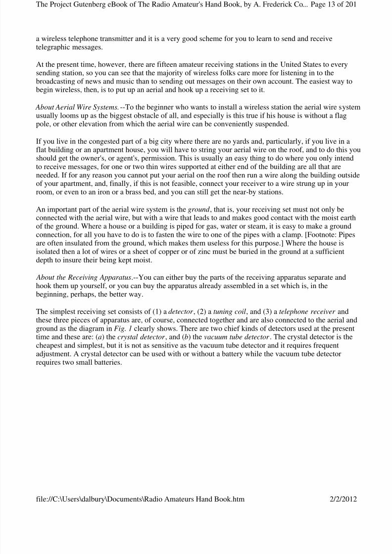
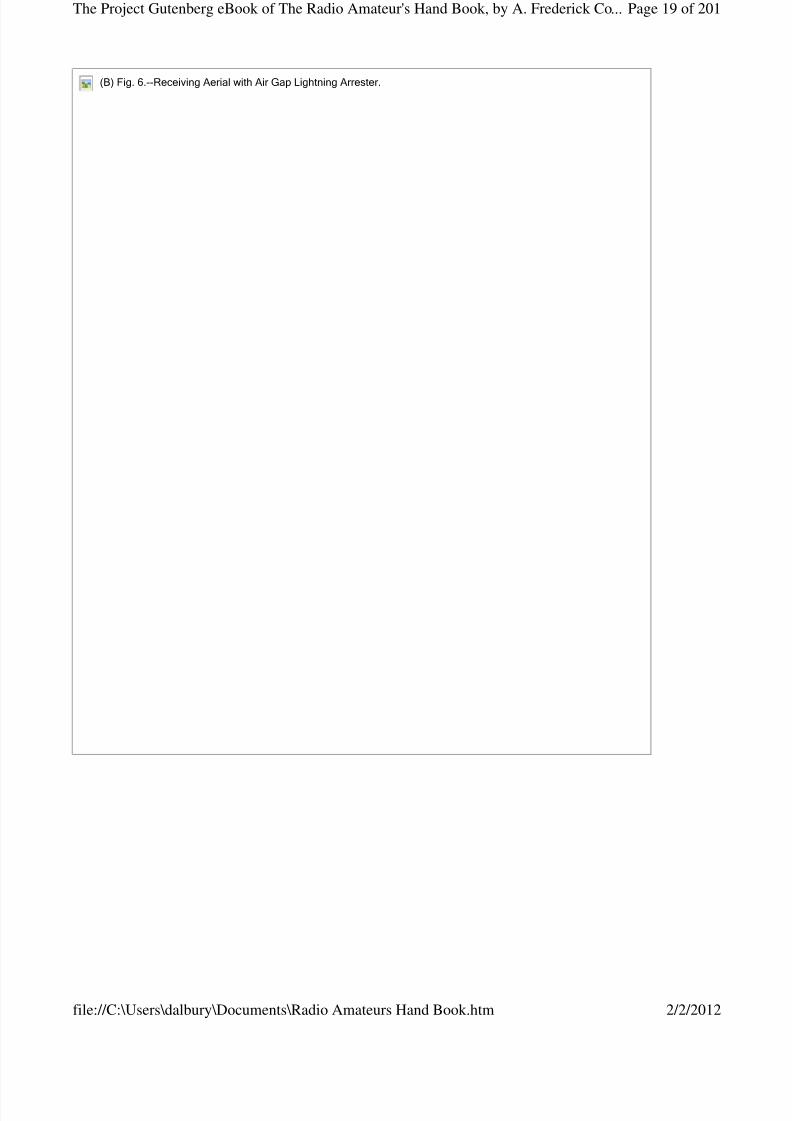
To make the aerial slip each end of the wire through a hole in each insulator and twist it fast; next cut off and slip two more pieces of wire through the other holes in the insulators and twist them fast and thensecure these to the supports at the ends of the building. Take the piece you are going to use for theleading-in wire, twist it around the aerial wire and solder it there when it will look like A in Fig. 6 . Now if you intend to use the air gap lightning arrester fasten it to the wall of the building outside of your
window, and bring the leading-in wire from the aerial to the top binding post of your arrester and keep itclear of everything as shown at B. If your aerial is on the roof and you have to bring the leading-in wireover the cornice or around a corner fix a porcelain knob insulator to the one or the other and fasten thewire to it.
Fig.5.--MaterialforaSimpleAerialWireSystem.
(A)Fig.6.--SingleWireAerialforReceiving.
Page 18 of 201The Project Gutenberg eBook of The Radio Amateur's Hand Book, by A. Frederick Co...
2/2/2012file://C:\Users\dalbury\Documents\Radio Amateurs Hand Book.htm
8/3/2019 Radio Amateurs Hand Book
http://slidepdf.com/reader/full/radio-amateurs-hand-book 19/201
(B)Fig.6.--ReceivingAerialwithAirGapLightningArrester.
Page 19 of 201The Project Gutenberg eBook of The Radio Amateur's Hand Book, by A. Frederick Co...
2/2/2012file://C:\Users\dalbury\Documents\Radio Amateurs Hand Book.htm
8/3/2019 Radio Amateurs Hand Book
http://slidepdf.com/reader/full/radio-amateurs-hand-book 20/201
Next bore a hole through the frame of the window at a point nearest your receiving set and push aporcelain tube 5/8 inch in diameter and 5 or 6 inches long, through it. Connect a length of wire to the toppost of the arrester or just above it to the wire, run this through the leading-in insulator and connect it tothe slider of your tuning coil. Screw the end of a piece of heavy copper wire to the lower post of thearrester and run it to the ground, on porcelain knobs if necessary, and solder it to an iron rod or pipewhich you have driven into the earth. Finally connect the fixed terminal of your tuning coil with the waterpipe or radiator inside of the house by means of the ground clamp as shown in the diagrammatic sketch at B in Fig. 6 and you are ready to tune in.
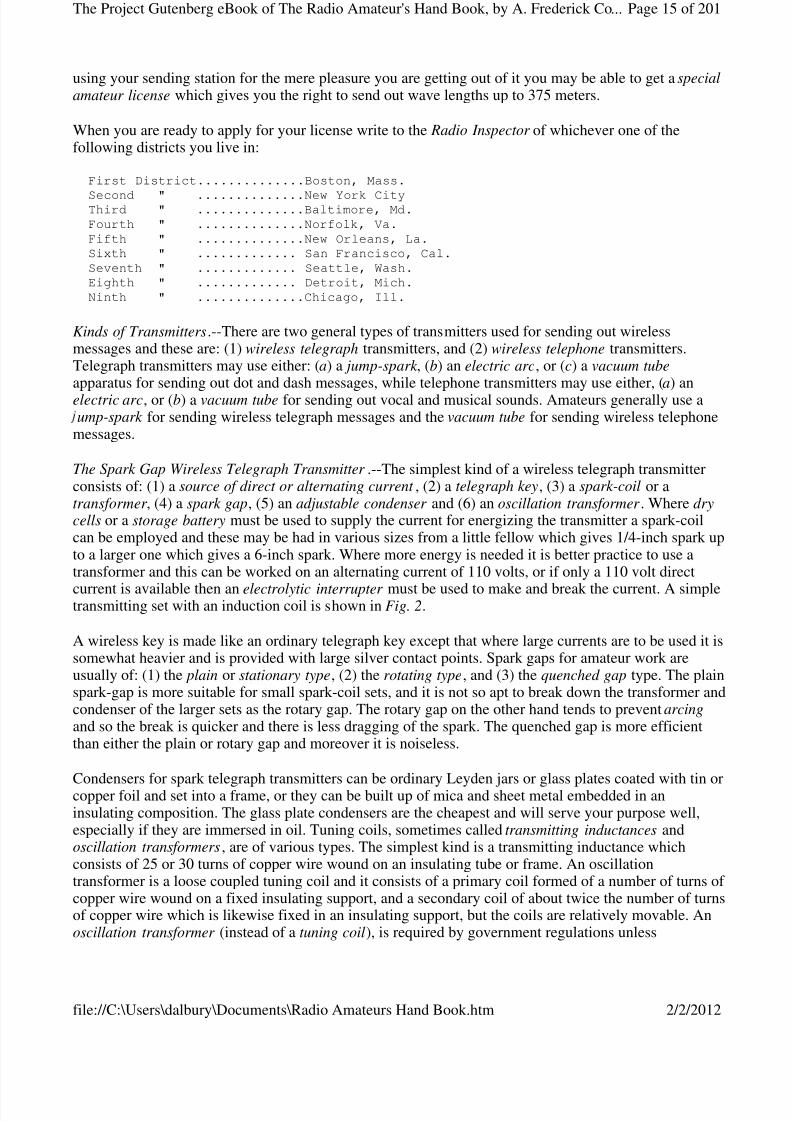
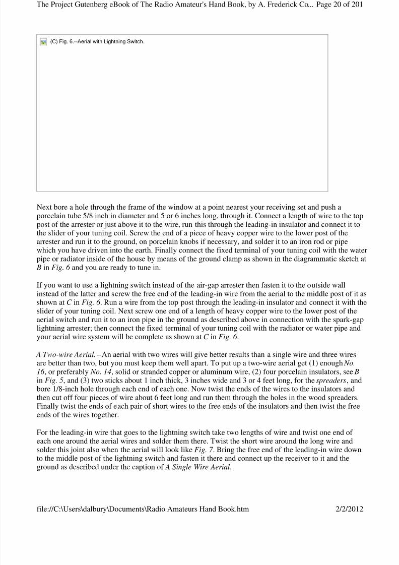
If you want to use a lightning switch instead of the air-gap arrester then fasten it to the outside wall
instead of the latter and screw the free end of the leading-in wire from the aerial to the middle post of it asshown at C in Fig. 6 . Run a wire from the top post through the leading-in insulator and connect it with theslider of your tuning coil. Next screw one end of a length of heavy copper wire to the lower post of theaerial switch and run it to an iron pipe in the ground as described above in connection with the spark-gaplightning arrester; then connect the fixed terminal of your tuning coil with the radiator or water pipe andyour aerial wire system will be complete as shown at C in Fig. 6 .
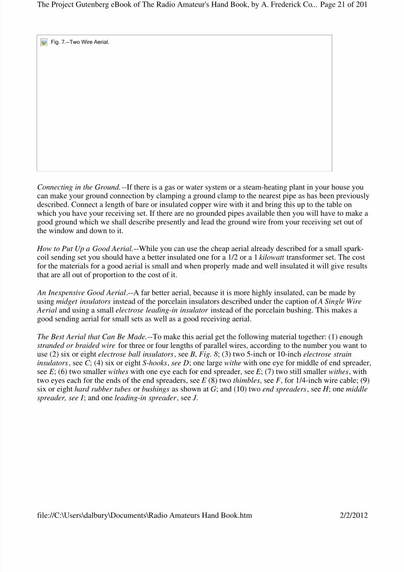
A Two-wire Aerial.--An aerial with two wires will give better results than a single wire and three wiresare better than two, but you must keep them well apart. To put up a two-wire aerial get (1) enough No.16 , or preferably No. 14, solid or stranded copper or aluminum wire, (2) four porcelain insulators, see B in Fig. 5, and (3) two sticks about 1 inch thick, 3 inches wide and 3 or 4 feet long, for the spreaders, andbore 1/8-inch hole through each end of each one. Now twist the ends of the wires to the insulators and
then cut off four pieces of wire about 6 feet long and run them through the holes in the wood spreaders.Finally twist the ends of each pair of short wires to the free ends of the insulators and then twist the freeends of the wires together.
For the leading-in wire that goes to the lightning switch take two lengths of wire and twist one end of each one around the aerial wires and solder them there. Twist the short wire around the long wire andsolder this joint also when the aerial will look like Fig. 7 . Bring the free end of the leading-in wire downto the middle post of the lightning switch and fasten it there and connect up the receiver to it and theground as described under the caption of A Single Wire Aerial.
(C)Fig.6.--AerialwithLightningSwitch.
Page 20 of 201The Project Gutenberg eBook of The Radio Amateur's Hand Book, by A. Frederick Co...
2/2/2012file://C:\Users\dalbury\Documents\Radio Amateurs Hand Book.htm
8/3/2019 Radio Amateurs Hand Book
http://slidepdf.com/reader/full/radio-amateurs-hand-book 21/201
Connecting in the Ground.--If there is a gas or water system or a steam-heating plant in your house youcan make your ground connection by clamping a ground clamp to the nearest pipe as has been previouslydescribed. Connect a length of bare or insulated copper wire with it and bring this up to the table onwhich you have your receiving set. If there are no grounded pipes available then you will have to make agood ground which we shall describe presently and lead the ground wire from your receiving set out of the window and down to it.
How to Put Up a Good Aerial.--While you can use the cheap aerial already described for a small spark-coil sending set you should have a better insulated one for a 1/2 or a 1 kilowatt transformer set. The costfor the materials for a good aerial is small and when properly made and well insulated it will give resultsthat are all out of proportion to the cost of it.
An Inexpensive Good Aerial.--A far better aerial, because it is more highly insulated, can be made by
using midget insulators instead of the porcelain insulators described under the caption of A Single Wire Aerial and using a small electrose leading-in insulator instead of the porcelain bushing. This makes agood sending aerial for small sets as well as a good receiving aerial.
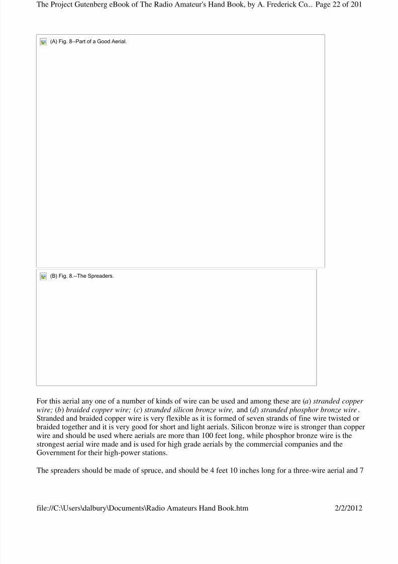
The Best Aerial that Can Be Made.--To make this aerial get the following material together: (1) enoughstranded or braided wire for three or four lengths of parallel wires, according to the number you want touse (2) six or eight electrose ball insulators, see B, Fig. 8; (3) two 5-inch or 10-inch electrose straininsulators, see C ; (4) six or eight S-hooks, see D; one large withe with one eye for middle of end spreader,see E ; (6) two smaller withes with one eye each for end spreader, see E ; (7) two still smaller withes, withtwo eyes each for the ends of the end spreaders, see E (8) two thimbles, see F , for 1/4-inch wire cable; (9)six or eight hard rubber tubes or bushings as shown at G; and (10) two end spreaders, see H ; one middle
spreader, see I ; and one leading-in spreader , see J .
Fig.7.--TwoWireAerial.
Page 21 of 201The Project Gutenberg eBook of The Radio Amateur's Hand Book, by A. Frederick Co...
2/2/2012file://C:\Users\dalbury\Documents\Radio Amateurs Hand Book.htm
8/3/2019 Radio Amateurs Hand Book
http://slidepdf.com/reader/full/radio-amateurs-hand-book 22/201
For this aerial any one of a number of kinds of wire can be used and among these are (a) stranded copper wire; (b) braided copper wire; (c) stranded silicon bronze wire, and (d ) stranded phosphor bronze wire.Stranded and braided copper wire is very flexible as it is formed of seven strands of fine wire twisted orbraided together and it is very good for short and light aerials. Silicon bronze wire is stronger than copperwire and should be used where aerials are more than 100 feet long, while phosphor bronze wire is thestrongest aerial wire made and is used for high grade aerials by the commercial companies and theGovernment for their high-power stations.
The spreaders should be made of spruce, and should be 4 feet 10 inches long for a three-wire aerial and 7
(A)Fig.8--PartofaGoodAerial.
(B)Fig.8.--TheSpreaders.
Page 22 of 201The Project Gutenberg eBook of The Radio Amateur's Hand Book, by A. Frederick Co...
2/2/2012file://C:\Users\dalbury\Documents\Radio Amateurs Hand Book.htm

8/3/2019 Radio Amateurs Hand Book
http://slidepdf.com/reader/full/radio-amateurs-hand-book 23/201
feet 1 inch long for a four-wire aerial as the distance between the wires should be about 27 inches. Theend spreaders can be turned cylindrically but it makes a better looking job if they taper from the middle tothe ends. They should be 2-1/4 inches in diameter at the middle and 1-3/4 inches at the ends. The middlespreader can be cylindrical and 2 inches in diameter. It must have holes bored through it at equidistantpoints for the hard rubber tubes; each of these should be 5/8 inch in diameter and have a hole 5/32 inch indiameter through it for the aerial wire. The leading-in spreader is also made of spruce and is 1-1/2 inchessquare and 26 inches long. Bore three or four 5/8-inch holes at equidistant points through this spreader
and insert hard rubber tubes in them as with the middle spreader.
Assembling the Aerial.--Begin by measuring off the length of each wire to be used and see to it that all of them are of exactly the same length. Now push the hard rubber insulators through the holes in the middlespreader and thread the wires through the holes in the insulators as shown at A in Fig 9.
Next twist the ends of each wire to the rings of the ball insulators and then put the large withes on themiddle of each of the end spreaders; fix the other withes on the spreaders so that they will be 27 inchesapart and fasten the ball insulators to the eyes in the withes with the S-hooks. Now slip a thimble throughthe eye of one of the long strain insulators, thread a length of stranded steel wire 1/4 inch in diameterthrough it and fasten the ends of it to the eyes in the withes on the ends of the spreaders.
(A)Fig.9.--MiddleSpreader.(B)Fig.9.--OneEndofAerialComplete.
Page 23 of 201The Project Gutenberg eBook of The Radio Amateur's Hand Book, by A. Frederick Co...
2/2/2012file://C:\Users\dalbury\Documents\Radio Amateurs Hand Book.htm
8/3/2019 Radio Amateurs Hand Book
http://slidepdf.com/reader/full/radio-amateurs-hand-book 24/201
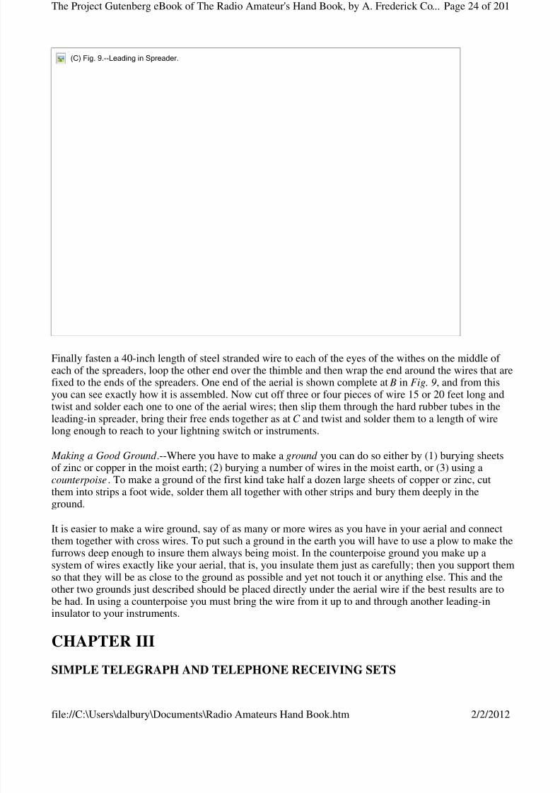
Finally fasten a 40-inch length of steel stranded wire to each of the eyes of the withes on the middle of each of the spreaders, loop the other end over the thimble and then wrap the end around the wires that arefixed to the ends of the spreaders. One end of the aerial is shown complete at B in Fig. 9, and from thisyou can see exactly how it is assembled. Now cut off three or four pieces of wire 15 or 20 feet long andtwist and solder each one to one of the aerial wires; then slip them through the hard rubber tubes in the
leading-in spreader, bring their free ends together as at C and twist and solder them to a length of wirelong enough to reach to your lightning switch or instruments.
Making a Good Ground .--Where you have to make a ground you can do so either by (1) burying sheetsof zinc or copper in the moist earth; (2) burying a number of wires in the moist earth, or (3) using acounterpoise. To make a ground of the first kind take half a dozen large sheets of copper or zinc, cutthem into strips a foot wide, solder them all together with other strips and bury them deeply in theground.
It is easier to make a wire ground, say of as many or more wires as you have in your aerial and connectthem together with cross wires. To put such a ground in the earth you will have to use a plow to make the
furrows deep enough to insure them always being moist. In the counterpoise ground you make up asystem of wires exactly like your aerial, that is, you insulate them just as carefully; then you support themso that they will be as close to the ground as possible and yet not touch it or anything else. This and theother two grounds just described should be placed directly under the aerial wire if the best results are tobe had. In using a counterpoise you must bring the wire from it up to and through another leading-ininsulator to your instruments.
CHAPTER III
SIMPLE TELEGRAPH AND TELEPHONE RECEIVING SETS
(C)Fig.9.--LeadinginSpreader.
Page 24 of 201The Project Gutenberg eBook of The Radio Amateur's Hand Book, by A. Frederick Co...
2/2/2012file://C:\Users\dalbury\Documents\Radio Amateurs Hand Book.htm
8/3/2019 Radio Amateurs Hand Book
http://slidepdf.com/reader/full/radio-amateurs-hand-book 25/201
With a crystal detector receiving set you can receive either telegraphic dots and dashes or telephonicspeech and music. You can buy a receiving set already assembled or you can buy the different parts andassemble them yourself. An assembled set is less bother in the beginning but if you like to experimentyou can hook up, that is, connect the separate parts together yourself and it is perhaps a little cheaper todo it this way. Then again, by so doing you get a lot of valuable experience in wireless work and anunderstanding of the workings of wireless that you cannot get in any other way.
Assembled Wireless Receiving Sets.--The cheapest assembled receiving set [Footnote: The Marvel, madeby the Radio Mfg. Co., New York City.] advertised is one in which the detector and tuning coil ismounted in a box. It costs $15.00, and can be bought of dealers in electric supplies generally.
This price also includes a crystal detector, an adjustable tuning coil, a single telephone receiver withhead-band and the wire, porcelain insulators, lightning switch and ground clamp for the aerial wiresystem. It will receive wireless telegraph and telephone messages over a range of from 10 to 25 miles.
Another cheap unit receptor, that is, a complete wireless receiving set already mounted which can be usedwith a single aerial is sold for $25.00. [Footnote: The Aeriola Jr., made by the Westinghouse Company,Pittsburgh, Pa.] This set includes a crystal detector, a variable tuning coil, a fixed condenser and a pair of
head telephone receivers. It can also be used to receive either telegraph or telephone messages fromdistances up to 25 miles. The aerial equipment is not included in this price, but it can be bought for about$2.50 extra.
Assembling Your Own Receiving Set .--In this chapter we shall go only into the apparatus used for twosimple receiving sets, both of which have a crystal detector . The first set includes a double-slide tuningcoil and the second set employs a loose-coupled tuning coil, or loose coupler , as it is called for short. Foreither set you can use a pair of 2,000- or 3,000-ohm head phones.
The Crystal Detector .--A crystal detector consists of: (1) the frame, (2) the crystal, and (3) the wire point .There are any number of different designs for frames, the idea being to provide a device that will (a) holdthe sensitive crystal firmly in place, and yet permit of its removal, (b) to permit the wire point , orelectrode, to be moved in any direction so that the free point of it can make contact with the mostsensitive spot on the crystal and (c) to vary the pressure of the wire on the crystal.
A simple detector frame is shown in the cross-section at A in Fig. 10; the crystal, which may be galena,silicon or iron pyrites, is held securely in a holder while the phosphor-bronze wire point which makescontact with it, is fixed to one end of a threaded rod on the other end of which is a knob. This rod screwsinto and through a sleeve fixed to a ball that sets between two brass standards and this permits an up anddown or a side to side adjustment of the metal point while the pressure of it on the crystal is regulated bythe screw.
Photograph unavailable
original © Underwood and Underwood.General Pershing Listening In.
Page 25 of 201The Project Gutenberg eBook of The Radio Amateur's Hand Book, by A. Frederick Co...
2/2/2012file://C:\Users\dalbury\Documents\Radio Amateurs Hand Book.htm
8/3/2019 Radio Amateurs Hand Book
http://slidepdf.com/reader/full/radio-amateurs-hand-book 26/201
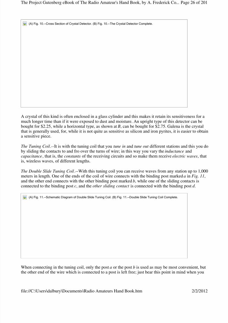
A crystal of this kind is often enclosed in a glass cylinder and this makes it retain its sensitiveness for amuch longer time than if it were exposed to dust and moisture. An upright type of this detector can bebought for $2.25, while a horizontal type, as shown at B, can be bought for $2.75. Galena is the crystalthat is generally used, for, while it is not quite as sensitive as silicon and iron pyrites, it is easier to obtaina sensitive piece.
The Tuning Coil.--It is with the tuning coil that you tune in and tune out different stations and this you doby sliding the contacts to and fro over the turns of wire; in this way you vary the inductance andcapacitance, that is, the constants of the receiving circuits and so make them receive electric waves, thatis, wireless waves, of different lengths.
The Double Slide Tuning Coil.--With this tuning coil you can receive waves from any station up to 1,000meters in length. One of the ends of the coil of wire connects with the binding post marked a in Fig. 11,and the other end connects with the other binding post marked b, while one of the sliding contacts isconnected to the binding post c, and the other sliding contact is connected with the binding post d .
When connecting in the tuning coil, only the post a or the post b is used as may be most convenient, butthe other end of the wire which is connected to a post is left free; just bear this point in mind when you
(A)Fig.10.--CrossSectionofCrystalDetector.(B)Fig.10.--TheCrystalDetectorComplete.
(A)Fig.11.--SchematicDiagramofDoubleSlideTuningCoil.(B)Fig.11.--DoubleSlideTuningCoilComplete.
Page 26 of 201The Project Gutenberg eBook of The Radio Amateur's Hand Book, by A. Frederick Co...
2/2/2012file://C:\Users\dalbury\Documents\Radio Amateurs Hand Book.htm

8/3/2019 Radio Amateurs Hand Book
http://slidepdf.com/reader/full/radio-amateurs-hand-book 27/201
come to connect the tuning coil up with the other parts of your receiving set. The tuning coil is showncomplete at B and it costs $3.00 or $4.00. A triple slide tuning coil constructed like the double slide tunerust described, only with more turns of wire on it, makes it possible to receive wave lengths up to 1,500
meters. It costs about $6.00.
The Loose Coupled Tuning Coil.--With a loose coupler , as this kind of a tuning coil is called for short,very selective tuning is possible, which means that you can tune in a station very sharply, and it will
receive any wave lengths according to size of coils. The primary coil is wound on a fixed cylinder and itsinductance is varied by means of a sliding contact like the double slide tuning coil described above. Thesecondary coil is wound on a cylinder that slides in and out of the primary coil. The inductance of thiscoil is varied by means of a switch that makes contact with the fixed points, each of which is connectedwith every twentieth turn of wire as shown in the diagram A in Fig. 12. The loose coupler, which isshown complete at B, costs in the neighborhood of $8.00 or $10.00.
Fixed and Variable Condensers.--You do not require a condenser for a simple receiving set, but if youwill connect a fixed condenser across your headphones you will get better results, while a variablecondenser connected in the closed circuit of a direct coupled receiving set , that is, one where a doubleslide tuning coil is used, makes it easy to tune very much more sharply; a variable condenser is absolutelynecessary where the circuits are inductively coupled , that is, where a loose coupled tuner is used.
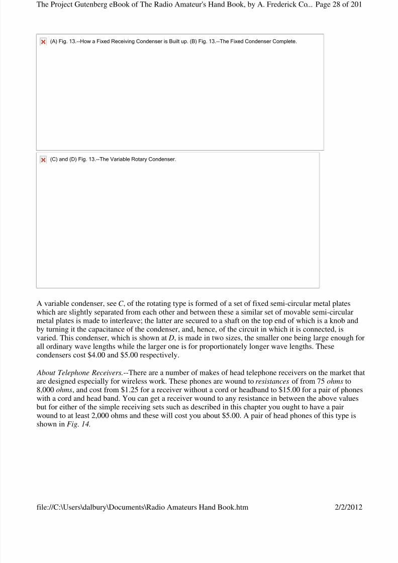
A fixed condenser consists of a number of sheets of paper with leaves of tin-foil in between them and sobuilt up that one end of every other leaf of tin-foil projects from the opposite end of the paper as shown at A in Fig. 13. The paper and tin-foil are then pressed together and impregnated with an insulatingcompound. A fixed condenser of the exact capacitance required for connecting across the head phones ismounted in a base fitted with binding posts, as shown at B, and costs 75 cents. (Paper ones 25 cents.)
(A)Fig.12.--SchematicDiagramofLooseCoupler.(B)Fig.12.--LooseCouplerComplete.
Page 27 of 201The Project Gutenberg eBook of The Radio Amateur's Hand Book, by A. Frederick Co...
2/2/2012file://C:\Users\dalbury\Documents\Radio Amateurs Hand Book.htm
8/3/2019 Radio Amateurs Hand Book
http://slidepdf.com/reader/full/radio-amateurs-hand-book 28/201
A variable condenser, see C , of the rotating type is formed of a set of fixed semi-circular metal plateswhich are slightly separated from each other and between these a similar set of movable semi-circularmetal plates is made to interleave; the latter are secured to a shaft on the top end of which is a knob andby turning it the capacitance of the condenser, and, hence, of the circuit in which it is connected, isvaried. This condenser, which is shown at D, is made in two sizes, the smaller one being large enough forall ordinary wave lengths while the larger one is for proportionately longer wave lengths. Thesecondensers cost $4.00 and $5.00 respectively.
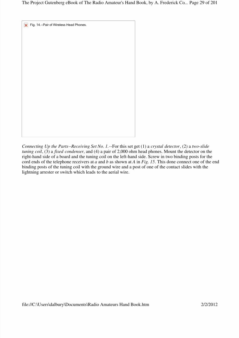
About Telephone Receivers.--There are a number of makes of head telephone receivers on the market thatare designed especially for wireless work. These phones are wound to resistances of from 75 ohms to8,000 ohms, and cost from $1.25 for a receiver without a cord or headband to $15.00 for a pair of phoneswith a cord and head band. You can get a receiver wound to any resistance in between the above valuesbut for either of the simple receiving sets such as described in this chapter you ought to have a pairwound to at least 2,000 ohms and these will cost you about $5.00. A pair of head phones of this type isshown in Fig. 14.
(A)Fig.13.--HowaFixedReceivingCondenserisBuiltup.(B)Fig.13.--TheFixedCondenserComplete.
(C)and(D)Fig.13.--TheVariableRotaryCondenser.
Page 28 of 201The Project Gutenberg eBook of The Radio Amateur's Hand Book, by A. Frederick Co...
2/2/2012file://C:\Users\dalbury\Documents\Radio Amateurs Hand Book.htm
8/3/2019 Radio Amateurs Hand Book
http://slidepdf.com/reader/full/radio-amateurs-hand-book 29/201
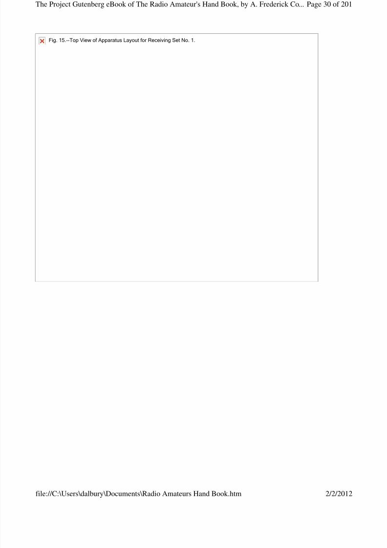
Connecting Up the Parts-- Receiving Set No. 1.--For this set get (1) a crystal detector , (2) a two-slidetuning coil, (3) a fixed condenser , and (4) a pair of 2,000 ohm head phones. Mount the detector on theright-hand side of a board and the tuning coil on the left-hand side. Screw in two binding posts for thecord ends of the telephone receivers at a and b as shown at A in Fig. 15. This done connect one of the endbinding posts of the tuning coil with the ground wire and a post of one of the contact slides with thelightning arrester or switch which leads to the aerial wire.
Fig.14.--PairofWirelessHeadPhones.
Page 29 of 201The Project Gutenberg eBook of The Radio Amateur's Hand Book, by A. Frederick Co...
2/2/2012file://C:\Users\dalbury\Documents\Radio Amateurs Hand Book.htm
8/3/2019 Radio Amateurs Hand Book
http://slidepdf.com/reader/full/radio-amateurs-hand-book 30/201
Fig.15.--TopViewofApparatusLayoutforReceivingSetNo.1.
Page 30 of 201The Project Gutenberg eBook of The Radio Amateur's Hand Book, by A. Frederick Co...
2/2/2012file://C:\Users\dalbury\Documents\Radio Amateurs Hand Book.htm
8/3/2019 Radio Amateurs Hand Book
http://slidepdf.com/reader/full/radio-amateurs-hand-book 31/201
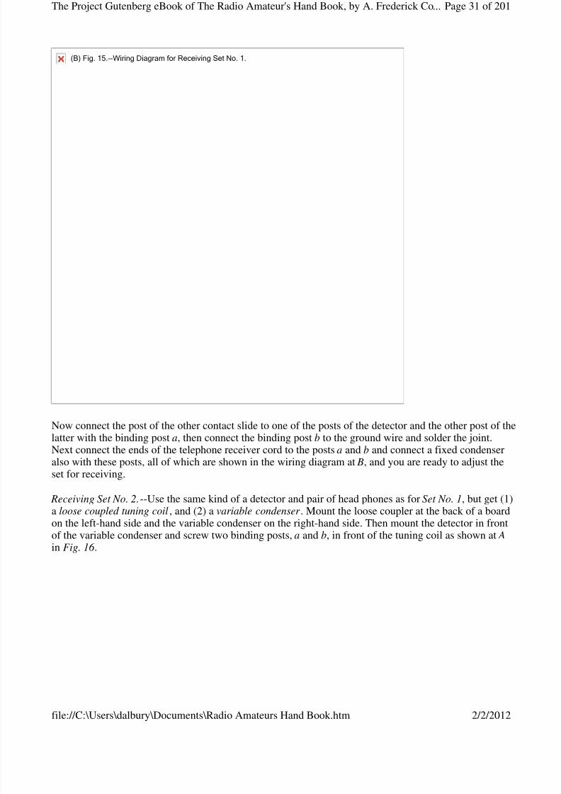
Now connect the post of the other contact slide to one of the posts of the detector and the other post of thelatter with the binding post a, then connect the binding post b to the ground wire and solder the joint.Next connect the ends of the telephone receiver cord to the posts a and b and connect a fixed condenseralso with these posts, all of which are shown in the wiring diagram at B, and you are ready to adjust theset for receiving.
Receiving Set No. 2.--Use the same kind of a detector and pair of head phones as for Set No. 1, but get (1)a loose coupled tuning coil, and (2) a variable condenser . Mount the loose coupler at the back of a boardon the left-hand side and the variable condenser on the right-hand side. Then mount the detector in frontof the variable condenser and screw two binding posts, a and b, in front of the tuning coil as shown at A in Fig. 16 .
(B)Fig.15.--WiringDiagramforReceivingSetNo.1.
Page 31 of 201The Project Gutenberg eBook of The Radio Amateur's Hand Book, by A. Frederick Co...
2/2/2012file://C:\Users\dalbury\Documents\Radio Amateurs Hand Book.htm

8/3/2019 Radio Amateurs Hand Book
http://slidepdf.com/reader/full/radio-amateurs-hand-book 32/201
Fig.16.--TopviewofApparatusLayoutforReceivingSetNo.2.
Page 32 of 201The Project Gutenberg eBook of The Radio Amateur's Hand Book, by A. Frederick Co...
2/2/2012file://C:\Users\dalbury\Documents\Radio Amateurs Hand Book.htm

8/3/2019 Radio Amateurs Hand Book
http://slidepdf.com/reader/full/radio-amateurs-hand-book 33/201
Now connect the post of the sliding contact of the loose coupler with the wire that runs to the lightning
switch and thence to the aerial; connect the post of the primary coil, which is the outside coil, with theground wire; then connect the binding post leading to the switch of the secondary coil, which is the insidecoil, with one of the posts of the variable condenser, and finally, connect the post that is joined to one endof the secondary coil with the other post of the variable condenser.
This done, connect one of the posts of the condenser with one of the posts of the detector, the other postof the detector with the binding post a, and the post b to the other post of the variable condenser. Nextconnect a fixed condenser to the binding posts a and b and then connect the telephone receivers to thesesame posts, all of which is shown in the wiring diagram at B. You are now ready to adjust theinstruments. In making the connections use No. 16 or 18 insulated copper wire and scrape the ends cleanwhere they go into the binding posts. See, also, that all of the connections are tight and where you have tocross the wires keep them apart by an inch or so and always cross them at right angles.
Adjusting the No. 1 Set --The Detector.--The first thing to do is to test the detector in order to find out if the point of the contact wire is on a sensitive spot of the crystal. To do this you need a buzzer , a switch and a dry cell. An electric bell from which the gong has been removed will do for the buzzer, but you canget one that is made specially for the purpose, for 75 cents, which gives out a clear, high-pitched note thatsounds like a high-power station.
Connect one of the binding posts of the buzzer with one post of the switch, the other post of the latterwith the zinc post of the dry cell and the carbon post of this to the other post of the buzzer. Then connectthe post of the buzzer that is joined to the vibrator, to the ground wire as shown in the wiring diagram,
(B)Fig.16.--WiringDiagramforReceivingSetNo.2.
Page 33 of 201The Project Gutenberg eBook of The Radio Amateur's Hand Book, by A. Frederick Co...
2/2/2012file://C:\Users\dalbury\Documents\Radio Amateurs Hand Book.htm
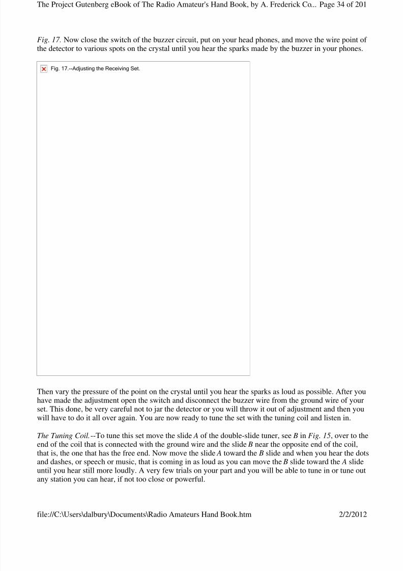
8/3/2019 Radio Amateurs Hand Book
http://slidepdf.com/reader/full/radio-amateurs-hand-book 34/201
Fig. 17. Now close the switch of the buzzer circuit, put on your head phones, and move the wire point of the detector to various spots on the crystal until you hear the sparks made by the buzzer in your phones.
Then vary the pressure of the point on the crystal until you hear the sparks as loud as possible. After you
have made the adjustment open the switch and disconnect the buzzer wire from the ground wire of yourset. This done, be very careful not to jar the detector or you will throw it out of adjustment and then youwill have to do it all over again. You are now ready to tune the set with the tuning coil and listen in.
The Tuning Coil.--To tune this set move the slide A of the double-slide tuner, see B in Fig. 15, over to theend of the coil that is connected with the ground wire and the slide B near the opposite end of the coil,that is, the one that has the free end. Now move the slide A toward the B slide and when you hear the dotsand dashes, or speech or music, that is coming in as loud as you can move the B slide toward the A slideuntil you hear still more loudly. A very few trials on your part and you will be able to tune in or tune outany station you can hear, if not too close or powerful.
Fig.17.--AdjustingtheReceivingSet.
Page 34 of 201The Project Gutenberg eBook of The Radio Amateur's Hand Book, by A. Frederick Co...
2/2/2012file://C:\Users\dalbury\Documents\Radio Amateurs Hand Book.htm
8/3/2019 Radio Amateurs Hand Book
http://slidepdf.com/reader/full/radio-amateurs-hand-book 35/201
Adjusting the No. 2 Set.--First adjust the crystal detector with the buzzer set as described above with Set No. 1, then turn the knob of your variable condenser so that the movable plates are just half-way in, pullthe secondary coil of your loose-coupled tuner half way out; turn the switch lever on it until it makes acontact with the middle contact point and set the slider of the primary coil half way between the ends.
Now listen in for telegraphic signals or telephonic speech or music; when you hear one or the other slidethe secondary coil in and out of the primary coil until the sounds are loudest; now move the contactswitch over the points forth and back until the sounds are still louder, then move the slider to and fro untilthe sounds are yet louder and, finally, turn the knob of the condenser until the sounds are clear and crisp.When you have done all of these things you have, in the parlance of the wireless operator, tuned in and
you are ready to receive whatever is being sent.
CHAPTER IV
SIMPLE TELEGRAPH SENDING SETS
A wireless telegraph transmitting set can be installed for a very small amount of money provided you arecontent with one that has a limited range. Larger and better instruments can, of course, be had for moremoney, but however much you are willing to spend still you are limited in your sending radius by theGovernment's rules and regulations. The best way, and the cheapest in the end, to install a telegraph set is
to buy the separate parts and hook them up yourself.
The usual type of wireless telegraph transmitter employs a disruptive discharge, or spark, as it is called,for setting up the oscillating currents in the aerial wire system and this is the type of apparatus describedin this chapter. There are two ways to set up the sparks and these are: (1) with an induction coil, or spark-coil, as it is commonly called, and (2) with an alternating current transformer , or power transformer , asit is sometimes called. Where you have to generate the current with a battery you must use a spark coil,but if you have a 110-volt direct or alternating lighting current in your home you can use a transformerwhich will give you more power.
A Cheap Transmitting Set (No. 1).--For this set you will need: (1) a spark-coil, (2) a battery of dry cells,(3) a telegraph key, (4) a spark gap, (5) a high-tension condenser , and (6) an oscillation transformer .
There are many different makes and styles of these parts but in the last analysis all of them are built onthe same underlying bases and work on the same fundamental principles.
The Spark-Coil.--Spark coils for wireless work are made to give sparks from 1/4 inch in length up to 6inches in length, but as a spark coil that gives less than a 1-inch spark has a very limited output it is bestto get a coil that gives at least a 1-inch spark, as this only costs about $8.00, and if you can get a 2- or a 4-inch spark coil so much the better. There are two general styles of spark coils used for wireless and theseare shown at A and B in Fig. 18.
Photograph unavailable
original © Underwood and Underwood.The World's Largest Radio Receiving Station. Owned by the Radio Corporation of America at
Rocky Point near Point Jefferson, L.I.
Page 35 of 201The Project Gutenberg eBook of The Radio Amateur's Hand Book, by A. Frederick Co...
2/2/2012file://C:\Users\dalbury\Documents\Radio Amateurs Hand Book.htm
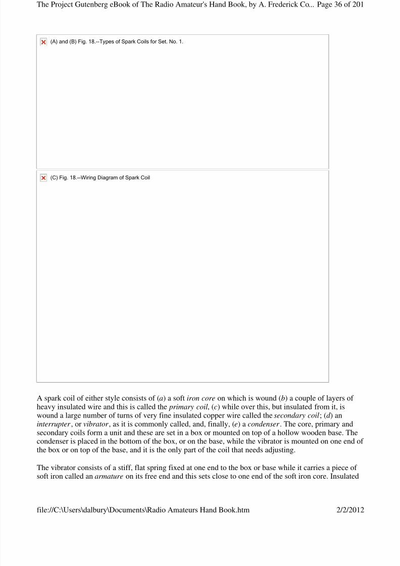
8/3/2019 Radio Amateurs Hand Book
http://slidepdf.com/reader/full/radio-amateurs-hand-book 36/201
A spark coil of either style consists of (a) a soft iron core on which is wound (b) a couple of layers of heavy insulated wire and this is called the primary coil, (c) while over this, but insulated from it, iswound a large number of turns of very fine insulated copper wire called the secondary coil; (d ) aninterrupter , or vibrator , as it is commonly called, and, finally, (e) a condenser . The core, primary andsecondary coils form a unit and these are set in a box or mounted on top of a hollow wooden base. Thecondenser is placed in the bottom of the box, or on the base, while the vibrator is mounted on one end of the box or on top of the base, and it is the only part of the coil that needs adjusting.
The vibrator consists of a stiff, flat spring fixed at one end to the box or base while it carries a piece of soft iron called an armature on its free end and this sets close to one end of the soft iron core. Insulated
(A)and(B)Fig.18.--TypesofSparkCoilsforSet.No.1.
(C)Fig.18.--WiringDiagramofSparkCoil
Page 36 of 201The Project Gutenberg eBook of The Radio Amateur's Hand Book, by A. Frederick Co...
2/2/2012file://C:\Users\dalbury\Documents\Radio Amateurs Hand Book.htm
8/3/2019 Radio Amateurs Hand Book
http://slidepdf.com/reader/full/radio-amateurs-hand-book 37/201
from this spring is a standard that carries an adjusting screw on the small end of which is a platinum pointand this makes contact with a small platinum disk fixed to the spring. The condenser is formed of alternate sheets of paper and tinfoil built up in the same fashion as the receiving condenser describedunder the caption of Fixed and Variable Condensers, in Chapter III.
The wiring diagram C shows how the spark coil is wired up. One of the battery binding posts isconnected with one end of the primary coil while the other end of the latter which is wound on the soft
iron core connects with the spring of the vibrator. The other battery binding post connects with thestandard that supports the adjusting screw. The condenser is shunted across the vibrator, that is, one endof the condenser is connected with the spring and the other end of the condenser is connected with theadjusting screw standard. The ends of the secondary coil lead to two binding posts, which are usuallyplaced on top of the spark coil and it is to these that the spark gap is connected.
The Battery.--This can be formed of dry cells or you can use a storage battery to energize your coil. Forall coils that give less than a 1-inch spark you should use 5 dry cells; for 1-and 2-inch spark coils use 6 or8 dry cells, and for 3 to 4-inch spark coils use 8 to 10 dry cells. The way the dry cells are connectedtogether to form a battery will be shown presently. A dry cell is shown at A in Fig, 19.
The Telegraph Key.--You can use an ordinary Morse telegraph key for the sending set and you can getone with a japanned iron base for $1.50 (or better, one made of brass and which has 1/8-inch silvercontact points for $3.00. A key of the latter kind is shown at B).
The Spark gap.--It is in the spark gap that the high tension spark takes place. The apparatus in which thespark takes place is also called the spark gap. It consists of a pair of zinc plugs, called electrodes, fixed tothe ends of a pair of threaded rods, with knobs on the other ends, and these screw into and through a pairof standards as shown at c. This is called a fixed , or stationary spark gap and costs about $1.00.
The Tuning Coil.--The transmitting inductance, or sending tuning coil, consists of 20 to 30 turns of No. 8
Fig.19.--OtherpartsforTransmittingSetNo.1
Page 37 of 201The Project Gutenberg eBook of The Radio Amateur's Hand Book, by A. Frederick Co...
2/2/2012file://C:\Users\dalbury\Documents\Radio Amateurs Hand Book.htm
8/3/2019 Radio Amateurs Hand Book
http://slidepdf.com/reader/full/radio-amateurs-hand-book 38/201
or 9 hard drawn copper wire wound on a slotted insulated form and mounted on a wooden base. It isprovided with clips so that you can cut in and cut out as many turns of wire as you wish and so tune thesending circuits to send out whatever wave length you desire. It is shown at d , and costs about $5.00. Seealso Oscillation Transformer , page 63 [Chapter IV].
The High Tension Condenser.--High tension condensers, that is, condensers which will stand up underhigh potentials, or electric pressures, can be bought in units or sections. These condensers are made up of
thin brass plates insulated with a special compound and pressed into a compact form. The capacitance [Footnote: This is the capacity of the condenser.] of one section is enough for a transmitting set using aspark coil that gives a 2 inch spark or less and two sections connected together should be used for coilsgiving from 2 to 4 inch sparks. It is shown at e.
Connecting Up the Apparatus.--Your sending set should be mounted on a table, or a bench, where it neednot be moved. Place the key in about the middle of the table and down in front, and the spark coil to theleft and well to the back but so that the vibrator end will be to the right, as this will enable you to adjust iteasily. Place the battery back of the spark coil and the tuning coil (oscillation transformer) to the right of the spark coil and back of the key, all of which is shown in the layout at A in Fig. 20.
(A)Fig.20.--TopViewofApparatusLayoutforSendingSetNo.1.
Page 38 of 201The Project Gutenberg eBook of The Radio Amateur's Hand Book, by A. Frederick Co...
2/2/2012file://C:\Users\dalbury\Documents\Radio Amateurs Hand Book.htm
8/3/2019 Radio Amateurs Hand Book
http://slidepdf.com/reader/full/radio-amateurs-hand-book 39/201
For the low voltage circuit , that is the battery circuit, use No. 12 or 14 insulated copper wire. Connect allof the dry cells together in series, that is, connect the zinc of one cell with the carbon of the next and soon until all of them are connected up. Then connect the carbon of the end cell with one of the posts of thekey, the zinc of the other end cell with one of the primary posts of the spark coil and the other primary
post of the spark coil with the other post of the key, when the primary circuit will be complete.
For the high tension circuits, that is, the oscillation circuits, you may use either bare or insulated copperwire but you must be careful that they do not touch the table, each other, or any part of the apparatus,except, of course, the posts they are connected with. Connect one of the posts of the secondary coil of thespark coil with one of the posts of the spark gap, and the other post with one of the posts of thecondenser; then connect the other post of the condenser with the lower spring clip of the tuning coil andalso connect this clip with the ground. This done, connect the middle spring clip with one of the posts of the spark gap, and, finally, connect the top clip with the aerial wire and your transmitting set is ready tobe tuned. A wiring diagram of the connections is shown at B. As this set is tuned in the same way as Set No. 2 which follows, you are referred to the end of this chapter.
A Better Transmitting Set (No. 2).--The apparatus for this set includes: (1) an alternating current transformer , (2) a wireless telegraph key, (3) a fixed , a rotary, or a quenched spark gap, (4) a condenser ,and (5) an oscillation transformer . If you have a 110 volt direct lighting current in your home instead of 110 volt alternating current, then you will also need (6) an electrolytic interrupter , for in this case theprimary circuit of the transformer must be made and broken rapidly in order to set up alternating currentsin the secondary coil.
The Alternating Current Transformer.--An alternating current, or power, transformer is made on the sameprinciple as a spark coil, that is, it has a soft iron core, a primary coil formed of a couple of layers of
(B)Fig.20.--WiringofDiagramforSendingSetNo.1.
Page 39 of 201The Project Gutenberg eBook of The Radio Amateur's Hand Book, by A. Frederick Co...
2/2/2012file://C:\Users\dalbury\Documents\Radio Amateurs Hand Book.htm

8/3/2019 Radio Amateurs Hand Book
http://slidepdf.com/reader/full/radio-amateurs-hand-book 40/201
heavy wire, and a secondary coil wound up of a large number of turns of very fine wire. Unlike the spark coil, however, which has an open magnetic core and whose secondary coil is wound on the primary coil,the transformer has a closed magnetic core, with the primary coil wound on one of the legs of the coreand the secondary wound on the other leg. It has neither a vibrator nor a condenser. A plain transformer isshown at A in Fig. 21.
A transformer of this kind can be bought either (a) unmounted , that is, just the bare transformer, or (b)
ully mounted , that is, fitted with an iron stand, mounted on an insulating base on which are a pair of primary binding posts, while the secondary is provided with a safety spark gap. There are three sizes of transformers of this kind made and they are rated at 1/4, 1/2 and 1 kilowatt, respectively, they deliver asecondary current of 9,000, 11,000 and 25,000 volts, according to size, and cost $16.00, $22.00 and$33.00 when fully mounted; a reduction of $3.00, $4.00 and $5.00 is made when they are unmounted. Allof these transformers operate on 110 volt, 60 cycle current and can be connected directly to the source of alternating current.
The Wireless Key.--For this transmitting set a standard wireless key should be used as shown at B. It ismade about the same as a regular telegraph key but it is much heavier, the contact points are larger and
Fig.21.--PartsforTransmittingSetNo.2.
Page 40 of 201The Project Gutenberg eBook of The Radio Amateur's Hand Book, by A. Frederick Co...
2/2/2012file://C:\Users\dalbury\Documents\Radio Amateurs Hand Book.htm

8/3/2019 Radio Amateurs Hand Book
http://slidepdf.com/reader/full/radio-amateurs-hand-book 41/201
instead of the current being led through the bearings as in an ordinary key, it is carried by heavyconductors directly to the contact points. This key is made in three sizes and the first will carry a currentof 5 amperes [Footnote: See Appendix for definition.] and costs $4.00, the second will carry a current of 10 amperes and costs $6.50, while the third will carry a current of 20 amperes and costs $7.50.
The Spark Gap.--Either a fixed, a rotary, or a quenched spark gap can be used with this set, but theformer is seldom used except with spark-coil sets, as it is very hard to keep the sparks from arcing when
large currents are used. A rotary spark gap comprises a wheel, driven by a small electric motor, withprojecting plugs, or electrodes, on it and a pair of stationary plugs on each side of the wheel as shown atC . The number of sparks per second can be varied by changing the speed of the wheel and when it isrotated rapidly it sends out signals of a high pitch which are easy to read at the receiving end. A rotarygap with a 110-volt motor costs about $25.00.
A quenched spark gap not only eliminates the noise of the ordinary gap but, when properly designed, itincreases the range of an induction coil set some 200 per cent. A 1/4 kilowatt quenched gap costs $10.00.[Footnote: See Appendix for definition.]
The High Tension Condenser .--Since, if you are an amateur, you can only send out waves that are 200
meters in length, you can only use a condenser that has a capacitance of .007 microfarad . [Footnote: SeeAppendix for definition.] A sectional high tension condenser like the one described in connection withSet No. 1 can be used with this set but it must have a capacitance of not more than .007 microfarad. Acondenser of this value for a 1/4-kilowatt transformer costs $7.00; for a 1/2-kilowatt transformer $14.00,and for a 1-kilowatt transformer $21.00. See E, Fig. 19.
The Oscillation Transformer .--With an oscillation transformer you can tune much more sharply than witha single inductance coil tuner. The primary coil is formed of 6 turns of copper strip, or No. 9 copper wire,and the secondary is formed of 9 turns of strip, or wire. The primary coil, which is the outside coil, ishinged to the base and can be raised or lowered like the lid of a box. When it is lowered the primary andsecondary coils are in the same plane and when it is raised the coils set at an angle to each other. It isshown at D and costs $5.00.
Connecting Up the Apparatus. For Alternating Current.--Screw the key to the table about the middle of itand near the front edge; place the high tension condenser back of it and the oscillation transformer back of the latter; set the alternating current transformer to the left of the oscillation transformer and place therotary or quenched spark gap in front of it.
Now bring a pair of No. 12 or 14 insulated wires from the 110 volt lighting leads and connect them with asingle-throw, double-pole switch; connect one pole of the switch with one of the posts of the primary coilof the alternating power transformer and connect the other post of the latter with one of the posts of yourkey, and the other post of this with the other pole of the switch. Now connect the motor of the rotaryspark gap to the power circuit and put a single-pole, single-throw switch in the motor circuit, all of which
is shown at A in Fig. 22.
Page 41 of 201The Project Gutenberg eBook of The Radio Amateur's Hand Book, by A. Frederick Co...
2/2/2012file://C:\Users\dalbury\Documents\Radio Amateurs Hand Book.htm

8/3/2019 Radio Amateurs Hand Book
http://slidepdf.com/reader/full/radio-amateurs-hand-book 42/201

8/3/2019 Radio Amateurs Hand Book
http://slidepdf.com/reader/full/radio-amateurs-hand-book 43/201
Next connect the posts of the secondary coil to the posts of the rotary or quenched spark gap and connectone post of the latter to one post of the condenser, the other post of this to the post of the primary coil of the oscillation transformer, which is the inside coil, and the clip of the primary coil to the other spark gap
post. This completes the closed oscillation circuit. Finally connect the post of the secondary coil of theoscillation transformer to the ground and the clip of it to the wire leading to the aerial when you are readyto tune the set. A wiring diagram of the connections is shown at B.
For Direct Current.--Where you have 110 volt direct current you must connect in an electrolyticinterrupter. This interrupter, which is shown at A and B in Fig. 23, consists of (1) a jar filled with asolution of 1 part of sulphuric acid and 9 parts of water, (2) a lead electrode having a large surfacefastened to the cover of surface that sets in a porcelain sleeve and whose end rests on the bottom of thear.
(B)Fig.22.--WiringDiagramforSendingSetNo.2.
Page 43 of 201The Project Gutenberg eBook of The Radio Amateur's Hand Book, by A. Frederick Co...
2/2/2012file://C:\Users\dalbury\Documents\Radio Amateurs Hand Book.htm

8/3/2019 Radio Amateurs Hand Book
http://slidepdf.com/reader/full/radio-amateurs-hand-book 44/201
When these electrodes are connected in series with the primary of a large spark coil or an alternatingcurrent transformer, see C , and a direct current of from 40 to 110 volts is made to pass through it, thecurrent is made and broken from 1,000 to 10,000 times a minute. By raising or lowering the sleeve, thusexposing more or less of the platinum, or alloy point, the number of interruptions per minute can bevaried at will. As the electrolytic interrupter will only operate in one direction, you must connect it with
its platinum, or alloy anode, to the + or positive power lead and the lead cathode to the - or negative power lead. You can find out which is which by connecting in the interrupter and trying it, or you can usea polarity indicator. An electrolytic interrupter can be bought for as little as $3.00.
How to Adjust Your Transmitter. Tuning With a Hot Wire Ammeter .--A transmitter can be tuned in twodifferent ways and these are: (1) by adjusting the length of the spark gap and the tuning coil so that thegreatest amount of energy is set up in the oscillating circuits, and (2) by adjusting the apparatus so that itwill send out waves of a given length.
To adjust the transmitter so that the circuits will be in tune you should have a hot wire ammeter , orradiation ammeter, as it is called, which is shown in Fig. 24. It consists of a thin platinum wire throughwhich the high-frequency currents surge and these heat it; the expansion and contraction of the wire
moves a needle over a scale marked off into fractions of an ampere. When the spark gap and tuning coilof your set are properly adjusted, the needle will swing farthest to the right over the scale and you willthen know that the aerial wire system, or open oscillation circuit, and the closed oscillation circuit are intune and radiating the greatest amount of energy.
Fig.23.--Using110VoltDirectCurrentwithanAlternatingCurrentTransformer.
Page 44 of 201The Project Gutenberg eBook of The Radio Amateur's Hand Book, by A. Frederick Co...
2/2/2012file://C:\Users\dalbury\Documents\Radio Amateurs Hand Book.htm
8/3/2019 Radio Amateurs Hand Book
http://slidepdf.com/reader/full/radio-amateurs-hand-book 45/201
To Send Out a 200 Meter Wave Length.--If you are using a condenser having a capacitance of .007microfarad, which is the largest capacity value that the Government will allow an amateur to use, then if you have a hot wire ammeter in your aerial and tune the inductance coil or coils until the ammeter showsthe largest amount of energy flowing through it you will know that your transmitter is tuned and that theaerial is sending out waves whose length is 200 meters. To tune to different wave lengths you must havea wave-meter .
The Use of the Aerial Switch.--Where you intend to install both a transmitter and a receptor you will needa throwover switch, or aerial switch, as it is called. An ordinary double-pole, double-throw switch, asshown at A in Fig. 25, can be used, or a switch made especially for the purpose as at B is handier becausethe arc of the throw is much less.
Fig.24.--PrincipleoftheHotWireAmmeter.
Page 45 of 201The Project Gutenberg eBook of The Radio Amateur's Hand Book, by A. Frederick Co...
2/2/2012file://C:\Users\dalbury\Documents\Radio Amateurs Hand Book.htm
8/3/2019 Radio Amateurs Hand Book
http://slidepdf.com/reader/full/radio-amateurs-hand-book 46/201
Aerial Switch for a Complete Sending and Receiving Set .--You can buy a double-pole, double-throw
switch mounted on a porcelain base for about 75 cents and this will serve for Set No. 1. Screw this switchon your table between the sending and receiving sets and then connect one of the middle posts of it withthe ground wire and the other middle post with the lightning switch which connects with the aerial.Connect the post of the tuning coil with one of the end posts of the switch and the clip of the tuning coilwith the other and complementary post of the switch. This done, connect one of the opposite end posts of the switch to the post of the receiving tuning coil and connect the sliding contact of the latter with theother and complementary post of the switch as shown in Fig. 26 .
Fig.25.--KindsofAerialSwitches.
Fig.26.--WiringDiagramforCompleteSendingandReceivingSetNo.1.
Page 46 of 201The Project Gutenberg eBook of The Radio Amateur's Hand Book, by A. Frederick Co...
2/2/2012file://C:\Users\dalbury\Documents\Radio Amateurs Hand Book.htm

8/3/2019 Radio Amateurs Hand Book
http://slidepdf.com/reader/full/radio-amateurs-hand-book 47/201
Connecting in the Lightning Switch.--The aerial wire connects with the middle post of the lightningswitch, while one of the end posts lead to one of the middle posts of the aerial switch. The other end postof the lightning switch leads to a separate ground outside the building, as the wiring diagrams Figs. 26 and 27 show.
CHAPTER V
ELECTRICITY SIMPLY EXPLAINED
It is easy to understand how electricity behaves and what it does if you get the right idea of it at the start.In the first place, if you will think of electricity as being a fluid like water its fundamental actions will begreatly simplified. Both water and electricity may be at rest or in motion. When at rest, under certainconditions, either one will develop pressure, and this pressure when released will cause them to flowthrough their respective conductors and thus produce a current.
Electricity at Rest and in Motion.--Any wire or a conductor of any kind can be charged with electricity,but a Leyden jar, or other condenser, is generally used to hold an electric charge because it has a muchlarger capacitance, as its capacity is called, than a wire. As a simple analogue of a condenser, supposeyou have a tank of water raised above a second tank and that these are connected together by means of apipe with a valve in it, as shown at A in Fig. 28.
Fig.27.--WiringDiagramforCompleteSendingandReceivingSetNo.2.
Page 47 of 201The Project Gutenberg eBook of The Radio Amateur's Hand Book, by A. Frederick Co...
2/2/2012file://C:\Users\dalbury\Documents\Radio Amateurs Hand Book.htm
8/3/2019 Radio Amateurs Hand Book
http://slidepdf.com/reader/full/radio-amateurs-hand-book 48/201
Now if you fill the upper tank with water and the valve is turned off, no water can flow into the lowertank but there is a difference of pressure between them, and the moment you turn the valve on a currentof water will flow through the pipe. In very much the same way when you have a condenser charged withelectricity the latter will be under pressure, that is, a difference of potential will be set up, for one of the
sheets of metal will be charged positively and the other one, which is insulated from it, will be chargednegatively, as shown at B. On closing the switch the opposite charges rush together and form a currentwhich flows to and fro between the metal plates. [Footnote: Strictly speaking it is the difference of potential that sets up the electromotive force.]
The Electric Current and Its Circuit .--Just as water flowing through a pipe has quantity and pressure back of it and the pipe offers friction to it which tends to hold back the water, so, likewise, doeselectricity flowing in a circuit have: (1) quantity, or current strength, or just current , as it is called forshort, or amperage, and (2) pressure, or potential difference, or electromotive force, or voltage, as it isvariously called, and the wire, or circuit, in which the current is flowing has (3) resistance which tends tohold back the current.
A definite relation exists between the current and its electromotive force and also between the current,electromotive force and the resistance of the circuit; and if you will get this relationship clearly in yourmind you will have a very good insight into how direct and alternating currents act. To keep a quantity of water flowing in a loop of pipe, which we will call the circuit, pressure must be applied to it and this maybe done by a rotary pump as shown at A in Fig. 29; in the same way, to keep a quantity of electricityflowing in a loop of wire, or circuit, a battery, or other means for generating electric pressure must beused, as shown at B.
Fig.28.--WaterAnalogueforElectricPressure.
Photograph unavailable
original © Underwood and Underwood.First Wireless College in the World, at Tufts College, Mass.
Page 48 of 201The Project Gutenberg eBook of The Radio Amateur's Hand Book, by A. Frederick Co...
2/2/2012file://C:\Users\dalbury\Documents\Radio Amateurs Hand Book.htm
8/3/2019 Radio Amateurs Hand Book
http://slidepdf.com/reader/full/radio-amateurs-hand-book 49/201
If you have a closed pipe connected with a piston pump, as at C , as the piston moves to and fro the water
in the pipe will move first one way and then the other. So also when an alternating current generator isconnected to a wire circuit, as at D, the current will flow first in one direction and then in the other, andthis is what is called an alternating current .
Current and the Ampere.--The amount of water flowing in a closed pipe is the same at all parts of it andthis is also true of an electric current, in that there is exactly the same quantity of electricity at one pointof the circuit as there is at any other.
The amount of electricity, or current, flowing in a circuit in a second is measured by a unit called theampere, [Footnote: For definition of ampere see Appendix.] and it is expressed by the symbol I.[Footnote: This is because the letter C is used for the symbol of capacitance] Just to give you an idea of
the quantity of current an ampere is we will say that a dry cell when fresh gives a current of about 20amperes. To measure the current in amperes an instrument called an ammeter is used, as shown at A inFig. 30, and this is always connected in series with the line, as shown at B.
Fig.29.--WaterAnaloguesforDirectandAlternatingCurrents.
Page 49 of 201The Project Gutenberg eBook of The Radio Amateur's Hand Book, by A. Frederick Co...
2/2/2012file://C:\Users\dalbury\Documents\Radio Amateurs Hand Book.htm
8/3/2019 Radio Amateurs Hand Book
http://slidepdf.com/reader/full/radio-amateurs-hand-book 50/201
Electromotive Force and the Volt .--When you have a pipe filled with water or a circuit charged withelectricity and you want to make them flow you must use a pump in the first case and a battery or adynamo in the second case. It is the battery or dynamo that sets up the electric pressure as the circuit itself is always charged with electricity.
The more cells you connect together in series the greater will be the electric pressure developed and themore current it will move along just as the amount of water flowing in a pipe can be increased byincreasing the pressure of the pump. The unit of electromotive force is the volt , and this is the electricpressure which will force a current of 1 ampere through a resistance of 1 ohm; it is expressed by the
symbol E . A fresh dry cell will deliver a current of about 1.5 volts. To measure the pressure of a currentin volts an instrument called a voltmeter is used, as shown at C in Fig. 30, and this is always connectedacross the circuit, as shown at D.
Resistance and the Ohm.--Just as a water pipe offers a certain amount of resistance to the flow of waterthrough it, so a circuit opposes the flow of electricity in it and this is called resistance. Further, in thesame way that a small pipe will not allow a large amount of water to flow through it, so, too, a thin wirelimits the flow of the current in it.
If you connect a resistance coil in a circuit it acts in the same way as partly closing the valve in a pipe, as
Fig.30.--HowtheAmmeterandVoltmeterareUsed.
Page 50 of 201The Project Gutenberg eBook of The Radio Amateur's Hand Book, by A. Frederick Co...
2/2/2012file://C:\Users\dalbury\Documents\Radio Amateurs Hand Book.htm
8/3/2019 Radio Amateurs Hand Book
http://slidepdf.com/reader/full/radio-amateurs-hand-book 51/201
shown at A and B in Fig. 31. The resistance of a circuit is measured by a unit called the ohm, and it isexpressed by the symbol R. A No. 10, Brown and Sharpe gauge soft copper wire, 1,000 feet long, has aresistance of about 1 ohm. To measure the resistance of a circuit an apparatus called a resistance bridge isused . The resistance of a circuit can, however, be easily calculated, as the following shows.
What Ohm's Law Is.--If, now, (1) you know what the current flowing in a circuit is in amperes, and theelectromotive force, or pressure, is in volts, you can then easily find what the resistance is in ohms of thecircuit in which the current is flowing by this formula:
Volts E--------- = Ohms, or --- = RAmperes I
That is, if you divide the current in amperes by the electromotive force in volts the quotient will give youthe resistance in ohms.
Or (2) if you know what the electromotive force of the current is in volts and the resistance of the circuitis in ohms then you can find what the current flowing in the circuit is in amperes, thus:
Volts E
----- = Amperes, or --- = IOhms R
That is, by dividing the resistance of the circuit in ohms, by the electromotive force of the current youwill get the amperes flowing in the circuit.
Finally (3) if you know what the resistance of the circuit is in ohms and the current is in amperes then youcan find what the electromotive force is in volts since:
Ohms x Amperes = Volts, or R x I = E
Fig.31.--WaterValveAnalogueofElectricResistance.A-avalvelimitstheflowofwater.B-aresistancelimitstheflowofcurrent.
Page 51 of 201The Project Gutenberg eBook of The Radio Amateur's Hand Book, by A. Frederick Co...
2/2/2012file://C:\Users\dalbury\Documents\Radio Amateurs Hand Book.htm
8/3/2019 Radio Amateurs Hand Book
http://slidepdf.com/reader/full/radio-amateurs-hand-book 52/201
That is, if you multiply the resistance of the circuit in ohms by the current in amperes the result will giveyou the electromotive force in volts.
From this you will see that if you know the value of any two of the constants you can find the value of theunknown constant by a simple arithmetical process. This relation between these three constants is knownas Ohm's Law and as they are very important you should memorize them.
What the Watt and Kilowatt Are.--Just as horsepower or H.P., is the unit of work that steam has done orcan do, so the watt is the unit of work that an electric current has done or can do. To find the watts acurrent develops you need only to multiply the amperes by the volts. There are 746 watts to 1horsepower, and 1,000 watts are equal to 1 kilowatt .
Electromagnetic Induction.--To show that a current of electricity sets up a magnetic field around it youhave only to hold a compass over a wire whose ends are connected with a battery when the needle willswing at right angles to the length of the wire. By winding an insulated wire into a coil and connectingthe ends of the latter with a battery you will find, if you test it with a compass, that the coil is magnetic.
This is due to the fact that the energy of an electric current flowing in the wire is partly changed into
magnetic lines of force which rotate at right angles about it as shown at A in Fig. 32. The magnetic fieldproduced by the current flowing in the coil is precisely the same as that set up by a permanent steelmagnet. Conversely, when a magnetic line of force is set up a part of its energy goes to make up electriccurrents which whirl about in a like manner, as shown at B.
(A)and(B)Fig.32.--HowanElectricCurrentisChangedintoMagneticLinesofForceandTheseintoanElectricCurrent.
Page 52 of 201The Project Gutenberg eBook of The Radio Amateur's Hand Book, by A. Frederick Co...
2/2/2012file://C:\Users\dalbury\Documents\Radio Amateurs Hand Book.htm

8/3/2019 Radio Amateurs Hand Book
http://slidepdf.com/reader/full/radio-amateurs-hand-book 53/201
Self-induction or Inductance.--When a current is made to flow in a coil of wire the magnetic lines of force produced are concentrated, as at C, just as a lens concentrates rays of light, and this forms anintense magnetic field , as it is called. Now if a bar of soft iron is brought close to one end of the coil of wire, or, better still, if it is pushed into the coil, it will be magnetized by electromagnetic induction, see D, and it will remain a magnet until the current is cut off.
Mutual Induction.--When two loops of wire, or better, two coils of wire, are placed close together theelectromagnetic induction between them is reactive, that is, when a current is made to flow through oneof the coils closed magnetic lines of force are set up and when these cut the other loop or turns of wire of the other coil, they in turn produce electric currents in it.
It is the mutual induction that takes place between two coils of wire which makes it possible to transformlow voltage currents from a battery or a 110 volt source of current into high pressure currents, or high
otential currents, as they are called, by means of a spark coil or a transformer, as well as to step up andstep down the potential of the high frequency currents that are set up in sending and receiving oscillationtransformers. Soft iron cores are not used in oscillation inductance coils and oscillation transformers forthe reason that the frequency of the current is so high the iron would not have time to magnetize anddemagnetize and so would not help along the mutual induction to any appreciable extent.
High-Frequency Currents.--High frequency currents, or electric oscillations as they are called, arecurrents of electricity that surge to and fro in a circuit a million times, more or less, per second. Currentsof such high frequencies will oscillate, that is, surge to and fro, in an open circuit , such as an aerial wire
(C)and(D)Fig.32.--HowanElectricCurrentSetsupaMagneticField.
Page 53 of 201The Project Gutenberg eBook of The Radio Amateur's Hand Book, by A. Frederick Co...
2/2/2012file://C:\Users\dalbury\Documents\Radio Amateurs Hand Book.htm
8/3/2019 Radio Amateurs Hand Book
http://slidepdf.com/reader/full/radio-amateurs-hand-book 54/201
system, as well as in a closed circuit .
Now there is only one method by which currents of high frequency, or radio-frequency, as they aretermed, can be set up by spark transmitters, and this is by discharging a charged condenser through acircuit having a small resistance. To charge a condenser a spark coil or a transformer is used and the endsof the secondary coil, which delivers the high potential alternating current, are connected with thecondenser. To discharge the condenser automatically a spark, or an arc, or the flow of electrons in a
vacuum tube, is employed.
Constants of an Oscillation Circuit.--An oscillation circuit, as pointed out before, is one in which highfrequency currents surge or oscillate. Now the number of times a high frequency current will surge forthand back in a circuit depends upon three factors of the latter and these are called the constants of thecircuit, namely: (1) its capacitance, (2) its inductance and (3) its resistance.
What Capacitance Is.--The word capacitance means the electrostatic capacity of a condenser or a circuit.The capacitance of a condenser or a circuit is the quantity of electricity which will raise its pressure, orpotential, to a given amount. The capacitance of a condenser or a circuit depends on its size and form andthe voltage of the current that is charging it.
The capacitance of a condenser or a circuit is directly proportional to the quantity of electricity that willkeep the charge at a given potential. The farad, whose symbol is M, is the unit of capacitance and acondenser or a circuit to have a capacitance of one farad must be of such size that one coulomb, which isthe unit of electrical quantity, will raise its charge to a potential of one volt. Since the farad is far toolarge for practical purposes a millionth of a farad, or microfarad , whose symbol is mfd., is used.
What Inductance Is.--Under the sub-caption of Self-induction and Inductance in the beginning of thischapter it was shown that it was the inductance of a coil that makes a current flowing through it produce astrong magnetic field, and here, as one of the constants of an oscillation circuit, it makes a high-frequencycurrent act as though it possessed inertia.
Inertia is that property of a material body that requires time and energy to set in motion, or stop.Inductance is that property of an oscillation circuit that makes an electric current take time to start andtime to stop. Because of the inductance, when a current flows through a circuit it causes the electricenergy to be absorbed and changes a large part of it into magnetic lines of force. Where high frequencycurrents surge in a circuit the inductance of it becomes a powerful factor. The practical unit of inductanceis the henry and it is represented by the symbol L.
What Resistance Is.--The resistance of a circuit to high-frequency currents is different from that for lowvoltage direct or alternating currents, as the former do not sink into the conductor to nearly so great anextent; in fact, they stick practically to the surface of it, and hence their flow is opposed to a very muchgreater extent. The resistance of a circuit to high frequency currents is generally found in the spark gap,
arc gap, or the space between the electrodes of a vacuum tube. The unit of resistance is, as stated, theohm, and its symbol is R.
The Effect of Capacitance, Inductance and Resistance on Electric Oscillations.--If an oscillation circuit inwhich high frequency currents surge has a large resistance, it will so oppose the flow of the currents thatthey will be damped out and reach zero gradually, as shown at A in Fig. 33. But if the resistance of thecircuit is small, and in wireless circuits it is usually so small as to be negligible, the currents will oscillate,until their energy is damped out by radiation and other losses, as shown at B.
Page 54 of 201The Project Gutenberg eBook of The Radio Amateur's Hand Book, by A. Frederick Co...
2/2/2012file://C:\Users\dalbury\Documents\Radio Amateurs Hand Book.htm

8/3/2019 Radio Amateurs Hand Book
http://slidepdf.com/reader/full/radio-amateurs-hand-book 55/201
As the capacitance and the inductance of the circuit, which may be made of any value, that is amount,you wish, determines the time period , that is, the length of time for a current to make one completeoscillation, it must be clear that by varying the values of the condenser and the inductance coil you canmake the high frequency current oscillate as fast or as slow as you wish within certain limits. Where theelectric oscillations that are set up are very fast, the waves sent out by the aerial will be short, and,conversely, where the oscillations are slow the waves emitted will be long.
CHAPTER VIHOW THE TRANSMITTING AND RECEIVING SETS WORK
The easiest way to get a clear conception of how a wireless transmitter sends out electric waves and howa wireless receptor receives them is to take each one separately and follow: (1) in the case of thetransmitter, the transformation of the low voltage direct, or alternating current into high potentialalternating currents; then find out how these charge the condenser, how this is discharged by the spark gap and sets up high-frequency currents in the oscillation circuits; then (2) in the case of the receptor, tofollow the high frequency currents that are set up in the aerial wire and learn how they are transformedinto oscillations of lower potential when they have a larger current strength, how these are converted intointermittent direct currents by the detector and which then flow into and operate the telephone receiver.
How Transmitting Set No. 1 Works. The Battery and Spark Coil Circuit .--When you press down on theknob of the key the silver points of it make contact and this closes the circuit; the low voltage directcurrent from the battery now flows through the primary coil of the spark coil and this magnetizes the softiron core. The instant it becomes magnetic it pulls the spring of the vibrator over to it and this breaks thecircuit; when this takes place the current stops flowing through the primary coil; this causes the core tolose its magnetism when the vibrator spring flies back and again makes contact with the adjusting screw;then the cycle of operations is repeated.
Fig.33.--TheEffectofResistanceontheDischargeofanElectricCurrent.
Page 55 of 201The Project Gutenberg eBook of The Radio Amateur's Hand Book, by A. Frederick Co...
2/2/2012file://C:\Users\dalbury\Documents\Radio Amateurs Hand Book.htm
8/3/2019 Radio Amateurs Hand Book
http://slidepdf.com/reader/full/radio-amateurs-hand-book 56/201
A condenser is connected across the contact points of the vibrator since this gives a much higher voltageat the ends of the secondary coil than where the coil is used without it; this is because: (1) the self-induction of the primary coil makes the pressure of the current rise and when the contact points close thecircuit again it discharges through the primary coil, and (2) when the break takes place the current flowsinto the condenser instead of arcing across the contact points.
Changing the Primary Spark Coil Current Into Secondary Currents.--Now every time the vibrator
contact points close the primary circuit the electric current in the primary coil is changed into closedmagnetic lines of force and as these cut through the secondary coil they set up in it a momentary current in one direction. Then the instant the vibrator points break apart the primary circuit is opened and theclosed magnetic lines of force contract and as they do so they cut the turns of wire in the secondary coilin the opposite direction and this sets up another momentary current in the secondary coil in the otherdirection. The result is that the low voltage direct current of the battery is changed into alternatingcurrents whose frequency is precisely that of the spring vibrator, but while the frequency of the currentsis low their potential, or voltage, is enormously increased.
What Ratio of Transformation Means.--To make a spark coil step up the low voltage direct current intohigh potential alternating current the primary coil is wound with a couple of layers of thick insulated
copper wire and the secondary is wound with a thousand, more or less, number of turns with very fineinsulated copper wire. If the primary and secondary coils were wound with the same number of turns of wire then the pressure, or voltage, of the secondary coil at its terminals would be the same as that of thecurrent which flowed through the primary coil. Under these conditions the ratio of transformation, as it iscalled, would be unity.
The ratio of transformation is directly proportional to the number of turns of wire on the primary andsecondary coils and, since this is the case, if you wind 10 turns of wire on the primary coil and 1,000turns of wire on the secondary coil then you will get 100 times as high a pressure, or voltage, at theterminals of the secondary as that which you caused to flow through the primary coil, but, naturally, thecurrent strength, or amperage, will be proportionately decreased.
The Secondary Spark Coil Circuit.--This includes the secondary coil and the spark gap which areconnected together. When the alternating, but high potential, currents which are developed by thesecondary coil, reach the balls, or electrodes, of the spark gap the latter are alternately charged positivelyand negatively.
Now take a given instant when one electrode is charged positively and the other one is chargednegatively, then when they are charged to a high enough potential the electric strain breaks down the airgap between them and the two charges rush together as described in the chapter before this one inconnection with the discharge of a condenser. When the charges rush together they form a current whichburns out the air in the gap and this gives rise to the spark, and as the heated gap between the twoelectrodes is a very good conductor the electric current surges forth and back with high frequency,
perhaps a dozen times, before the air replaces that which has burned out. It is the inrushing air to fill thevacuum of the gap that makes the crackling noise which accompanies the discharge of the electric spark.
In this way then electric oscillations of the order of a million, more or less, are produced and if an aerialand a ground wire are connected to the spark balls, or electrodes, the oscillations will surge up and downit and the energy of these in turn, are changed into electric waves which travel out into space. An opencircuit transmitter of this kind will send out waves that are four times as long as the aerial itself, but as thewaves it sends out are strongly damped the Government will not permit it to be used.
The Closed Oscillation Circuit.--By using a closed oscillation circuit the transmitter can be tuned to send
Page 56 of 201The Project Gutenberg eBook of The Radio Amateur's Hand Book, by A. Frederick Co...
2/2/2012file://C:\Users\dalbury\Documents\Radio Amateurs Hand Book.htm

8/3/2019 Radio Amateurs Hand Book
http://slidepdf.com/reader/full/radio-amateurs-hand-book 57/201
out waves of a given length and while the waves are not so strongly damped more current can be sent intothe aerial wire system. The closed oscillation circuit consists of: (1) a spark gap, (2) a condenser and (3)an oscillation transformer . The high potential alternating current delivered by the secondary coil not onlycharges the spark gap electrodes which necessarily have a very small capacitance, but it charges thecondenser which has a large capacitance and the value of which can be changed at will.
Now when the condenser is fully charged it discharges through the spark gap and then the electric
oscillations set up surge to and fro through the closed circuit. As a closed circuit is a very poor radiator of energy, that is, the electric oscillations are not freely converted into electric waves by it, they surge up to,and through the aerial wire; now as the aerial wire is a good radiator nearly all of the energy of theelectric oscillations which surge through it are converted into electric waves.
How Transmitting Set No. 2 Works. With Alternating Current. The operation of a transmitting set thatuses an alternating current transformer, or power transformer, as it is sometimes called, is even moresimple than one using a spark coil. The transformer needs no vibrator when used with alternating current.The current from a generator flows through the primary coil of the transformer and the alternations of theusual lighting current is 60 cycles per second. This current sets up an alternating magnetic field in thecore of the transformer and as these magnetic lines of force expand and contract they set up alternating
currents of the same frequency but of much higher voltage at the terminals of the secondary coilaccording to the ratio of the primary and secondary turns of wire as explained under the sub-caption of Ratio of Transformation.
With Direct Current .--When a 110 volt direct current is used to energize the power transformer anelectrolytic interruptor is needed to make and break the primary circuit, just as a vibrator is needed for thesame purpose with a spark coil. When the electrodes are connected in series with the primary coil of atransformer and a source of direct current having a potential of 40 to 110 volts, bubbles of gas are formedon the end of the platinum, or alloy anode, which prevent the current from flowing until the bubblesbreak and then the current flows again, in this way the current is rapidly made and broken and the break is very sharp.
Where this type of interrupter is employed the condenser that is usually shunted around the break is notnecessary as the interrupter itself has a certain inherent capacitance, due to electrolytic action, and whichis called its electrolytic capacitance, and this is large enough to balance the self-induction of the circuitsince the greater the number of breaks per minute the smaller the capacitance required.
The Rotary Spark Gap.--In this type of spark gap the two fixed electrodes are connected with theterminals of the secondary coil of the power transformer and also with the condenser and primary of theoscillation transformer. Now whenever any pair of electrodes on the rotating disk are in a line with thepair of fixed electrodes a spark will take place, hence the pitch of the note depends on the speed of themotor driving the disk. This kind of a rotary spark-gap is called non-synchronous and it is generally usedwhere a 60 cycle alternating current is available but it will work with other higher frequencies.
The Quenched Spark Gap.--If you strike a piano string a single quick blow it will continue to vibrateaccording to its natural period. This is very much the way in which a quenched spark gap sets uposcillations in a coupled closed and open circuit. The oscillations set up in the primary circuit by aquenched spark make only three or four sharp swings and in so doing transfer all of their energy over tothe secondary circuit, where it will oscillate some fifty times or more before it is damped out, because thehigh frequency currents are not forced, but simply oscillate to the natural frequency of the circuit. For thisreason the radiated waves approach somewhat the condition of continuous waves, and so sharper tuningis possible.
Page 57 of 201The Project Gutenberg eBook of The Radio Amateur's Hand Book, by A. Frederick Co...
2/2/2012file://C:\Users\dalbury\Documents\Radio Amateurs Hand Book.htm
8/3/2019 Radio Amateurs Hand Book
http://slidepdf.com/reader/full/radio-amateurs-hand-book 58/201
The Oscillation Transformer.--In this set the condenser in the closed circuit is charged and dischargedand sets up oscillations that surge through the closed circuit as in Set No. 1. In this set, however, anoscillation transformer is used and as the primary coil of it is included in the closed circuit the oscillationsset up in it produce strong oscillating magnetic lines of force. The magnetic field thus produced sets up inturn electric oscillations in the secondary coil of the oscillation transformer and these surge through theaerial wire system where their energy is radiated in the form of electric waves.
The great advantage of using an oscillation transformer instead of a simple inductance coil is that thecapacitance of the closed circuit can be very much larger than that of the aerial wire system. This permitsmore energy to be stored up by the condenser and this is impressed on the aerial when it is radiated aselectric waves.
How Receiving Set No. I Works.--When the electric waves from a distant sending station impinge on thewire of a receiving aerial their energy is changed into electric oscillations that are of exactly the samefrequency (assuming the receptor is tuned to the transmitter) but whose current strength (amperage) andpotential (voltage) are very small. These electric waves surge through the closed circuit but when theyreach the crystal detector the contact of the metal point on the crystal permits more current to flowthrough it in one direction than it will allow to pass in the other direction. For this reason a crystal
detector is sometimes called a rectifier , which it really is.
Thus the high frequency currents which the steel magnet cores of the telephone receiver would choke off are changed by the detector into intermittent direct currents which can flow through the magnet coils of the telephone receiver. Since the telephone receiver chokes off the oscillations, a small condenser can beshunted around it so that a complete closed oscillation circuit is formed and this gives better results.
When the intermittent rectified current flows through the coils of the telephone receiver it energizes themagnet as long as it lasts, when it is de-energized; this causes the soft iron disk, or diaphragm as it iscalled, which sets close to the ends of the poles of the magnet, to vibrate; and this in turn gives forthsounds such as dots and dashes, speech or music, according to the nature of the electric waves that sentthem out at the distant station.
How Receiving Set No. 2 Works.--When the electric oscillations that are set up by the incoming electricwaves on the aerial wire surge through the primary coil of the oscillation transformer they produce amagnetic field and as the lines of force of the latter cut the secondary coil, oscillations of the samefrequency are set up in it. The potential (voltage) of these oscillations are, however, stepped down in thesecondary coil and, hence, their current strength (amperes) is increased.
The oscillations then flow through the closed circuit where they are rectified by the crystal detector andtransformed into sound waves by the telephone receiver as described in connection with Set No. 1. Thevariable condenser shunted across the closed circuit permits finer secondary tuning to be done than ispossible without it. Where you are receiving continuous waves from a wireless telephone transmitter
(speech or music) you have to tune sharper than is possible with the tuning coil alone and to do this avariable condenser connected in parallel with the secondary coil is necessary.
CHAPTER VII
MECHANICAL AND ELECTRICAL TUNING
There is a strikingly close resemblance between sound waves and the way they are set up in the air by amechanically vibrating body, such as a steel spring or a tuning fork, and electric waves and the way they
Page 58 of 201The Project Gutenberg eBook of The Radio Amateur's Hand Book, by A. Frederick Co...
2/2/2012file://C:\Users\dalbury\Documents\Radio Amateurs Hand Book.htm
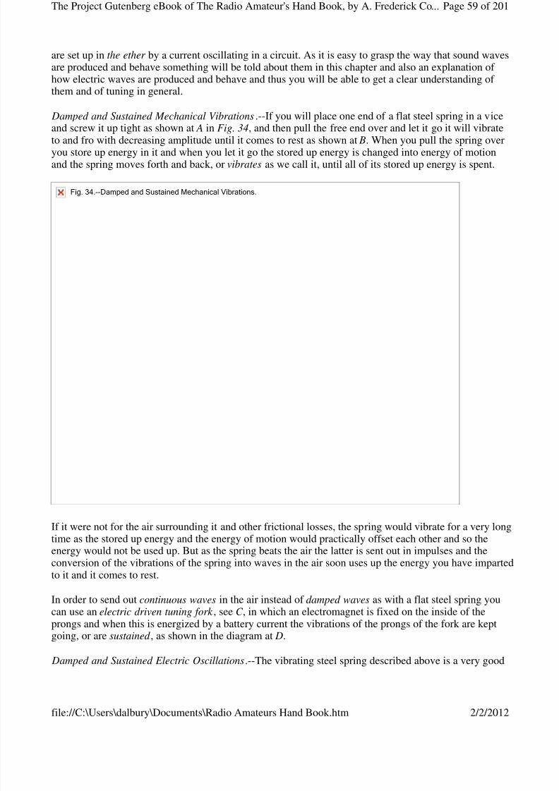
8/3/2019 Radio Amateurs Hand Book
http://slidepdf.com/reader/full/radio-amateurs-hand-book 59/201

8/3/2019 Radio Amateurs Hand Book
http://slidepdf.com/reader/full/radio-amateurs-hand-book 60/201
analogue of the way that damped electric oscillations which surge in a circuit set up and send out periodicelectric waves in the ether while the electric driven tuning fork just described is likewise a good analogueof how sustained oscillations surge in a circuit and set up and send out continuous electric waves in theether as the following shows.
Now the inductance and resistance of a circuit such as is shown at A in Fig. 35, slows down, and finallydamps out entirely, the electric oscillations of the high frequency currents, see B, where these are set up
by the periodic discharge of a condenser, precisely as the vibrations of the spring are damped out by thefriction of the air and other resistances that act upon it. As the electric oscillations surge to and fro in thecircuit it is opposed by the action of the ether which surrounds it and electric waves are set up in and sentout through it and this transformation soon uses up the energy of the current that flows in the circuit.
To send out continuous waves in the ether such as are needed for wireless telephony instead of damped waves which are, at the present writing, generally used for wireless telegraphy, an electric oscillation arc or a vacuum tube oscillator must be used, see C , instead of a spark gap. Where a spark gap is used thecondenser in the circuit is charged periodically and with considerable lapses of time between each of thecharging processes, when, of course, the condenser discharges periodically and with the same timeelement between them. Where an oscillation arc or a vacuum tube is used the condenser is charged asrapidly as it is discharged and the result is the oscillations are sustained as shown at D.
About Mechanical Tuning.--A tuning fork is better than a spring or a straight steel bar for setting upmechanical vibrations. As a matter of fact a tuning fork is simply a steel bar bent in the middle so that thetwo ends are parallel. A handle is attached to middle point of the fork so that it can be held easily andwhich also allows it to vibrate freely, when the ends of the prongs alternately approach and recede fromone another. When the prongs vibrate the handle vibrates up and down in unison with it, and imparts itsmotion to the sounding box, or resonance case as it is sometimes called, where one is used.
Fig.35.--DampedandSustainedElectricOscillations.
Page 60 of 201The Project Gutenberg eBook of The Radio Amateur's Hand Book, by A. Frederick Co...
2/2/2012file://C:\Users\dalbury\Documents\Radio Amateurs Hand Book.htm
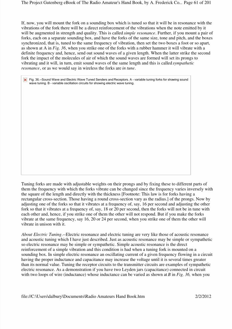
8/3/2019 Radio Amateurs Hand Book
http://slidepdf.com/reader/full/radio-amateurs-hand-book 61/201
If, now, you will mount the fork on a sounding box which is tuned so that it will be in resonance with thevibrations of the fork there will be a direct reinforcement of the vibrations when the note emitted by itwill be augmented in strength and quality. This is called simple resonance. Further, if you mount a pair of forks, each on a separate sounding box, and have the forks of the same size, tone and pitch, and the boxessynchronized, that is, tuned to the same frequency of vibration, then set the two boxes a foot or so apart,as shown at A in Fig. 36 , when you strike one of the forks with a rubber hammer it will vibrate with adefinite frequency and, hence, send out sound waves of a given length. When the latter strike the second
fork the impact of the molecules of air of which the sound waves are formed will set its prongs tovibrating and it will, in turn, emit sound waves of the same length and this is called sympatheticresonance, or as we would say in wireless the forks are in tune.
Tuning forks are made with adjustable weights on their prongs and by fixing these to different parts of them the frequency with which the forks vibrate can be changed since the frequency varies inversely withthe square of the length and directly with the thickness [Footnote: This law is for forks having arectangular cross-section. Those having a round cross-section vary as the radius.] of the prongs. Now byadjusting one of the forks so that it vibrates at a frequency of, say, 16 per second and adjusting the otherfork so that it vibrates at a frequency of, say, 18 or 20 per second, then the forks will not be in tune witheach other and, hence, if you strike one of them the other will not respond. But if you make the forksvibrate at the same frequency, say 16, 20 or 24 per second, when you strike one of them the other willvibrate in unison with it.
About Electric Tuning.--Electric resonance and electric tuning are very like those of acoustic resonanceand acoustic tuning which I have just described. Just as acoustic resonance may be simple or sympatheticso electric resonance may be simple or sympathetic. Simple acoustic resonance is the directreinforcement of a simple vibration and this condition is had when a tuning fork is mounted on asounding box. In simple electric resonance an oscillating current of a given frequency flowing in a circuithaving the proper inductance and capacitance may increase the voltage until it is several times greaterthan its normal value. Tuning the receptor circuits to the transmitter circuits are examples of sympatheticelectric resonance. As a demonstration if you have two Leyden jars (capacitance) connected in circuitwith two loops of wire (inductance) whose inductance can be varied as shown at B in Fig. 36, when you
Fig.36.--SoundWaveandElectricWaveTunedSendersandReceptors.A-variabletuningforksforshowingsoundwavetuning.B-variableoscillationcircuitsforshowingelectricwavetuning.
Page 61 of 201The Project Gutenberg eBook of The Radio Amateur's Hand Book, by A. Frederick Co...
2/2/2012file://C:\Users\dalbury\Documents\Radio Amateurs Hand Book.htm
8/3/2019 Radio Amateurs Hand Book
http://slidepdf.com/reader/full/radio-amateurs-hand-book 62/201
make a spark pass between the knobs of one of them by means of a spark coil then a spark will pass in thegap of the other one provided the inductance of the two loops of wire is the same. But if you vary theinductance of the one loop so that it is larger or smaller than that of the other loop no spark will takeplace in the second circuit.
When a tuning fork is made to vibrate it sends out waves in the air, or sound waves, in all directions andust so when high frequency currents surge in an oscillation circuit they send out waves in the ether, or
electric waves, that travel in all directions. For this reason electric waves from a transmitting stationcannot be sent to one particular station, though they do go further in one direction than in another,according to the way your aerial wire points.
Since the electric waves travel out in all directions any receiving set properly tuned to the wave length of the sending station will receive the waves and the only limit on your ability to receive from high-powerstations throughout the world depends entirely on the wave length and sensitivity of your receiving set.As for tuning, just as changing the length and the thickness of the prongs of a tuning fork varies thefrequency with which it vibrates and, hence, the length of the waves it sends out, so, too, by varying thecapacitance of the condenser and the inductance of the tuning coil of the transmitter the frequency of theelectric oscillations set up in the circuit may be changed and, consequently, the length of the electric
waves they send out. Likewise, by varying the capacitance and the inductance of the receptor the circuitscan be tuned to receive incoming electric waves of whatever length within the limitation of the apparatus.
CHAPTER VIII
A SIMPLE VACUUM TUBE DETECTOR RECEIVING SET
While you can receive dots and dashes from spark wireless telegraph stations and hear spoken words andmusic from wireless telephone stations with a crystal detector receiving set such as described in ChapterIII, you can get stations that are much farther away and hear them better with a vacuum tube detector receiving set.
Though the vacuum tube detector requires two batteries to operate it and the receiving circuits aresomewhat more complicated than where a crystal detector is used still the former does not have to beconstantly adjusted as does the latter and this is another very great advantage. Taken all in all the vacuumtube detector is the most sensitive and the most satisfactory of the detectors that are in use at the presenttime.
Not only is the vacuum tube a detector of electric wave signals and speech and music but it can also beused to amplify them, that is, to make them stronger and, hence, louder in the telephone receiver andfurther its powers of amplification are so great that it will reproduce them by means of a loud speaker ,ust as a horn amplifies the sounds of a phonograph reproducer, until they can be heard by a room or an
auditorium full of people. There are two general types of loud speakers, though both use the principle of the telephone receiver. The construction of these loud speakers will be fully described in a later chapter.
Assembled Vacuum Tube Receiving Sets.--You can buy a receiving set with a vacuum tube detector fromthe very simplest type, which is described in this chapter, to those that are provided with regenerativecircuits and amplifying tubes or both, which we shall describe in later chapters, from dealers in electricalapparatus generally. While one of these sets costs more than you can assemble a set for yourself, still,especially in the beginning, it is a good plan to buy an assembled one for it is fitted with a panel on whichthe adjusting knobs of the rheostat, tuning coil and condenser are mounted and this makes it possible tooperate it as soon as you get it home and without the slightest trouble on your part.
Page 62 of 201The Project Gutenberg eBook of The Radio Amateur's Hand Book, by A. Frederick Co...
2/2/2012file://C:\Users\dalbury\Documents\Radio Amateurs Hand Book.htm
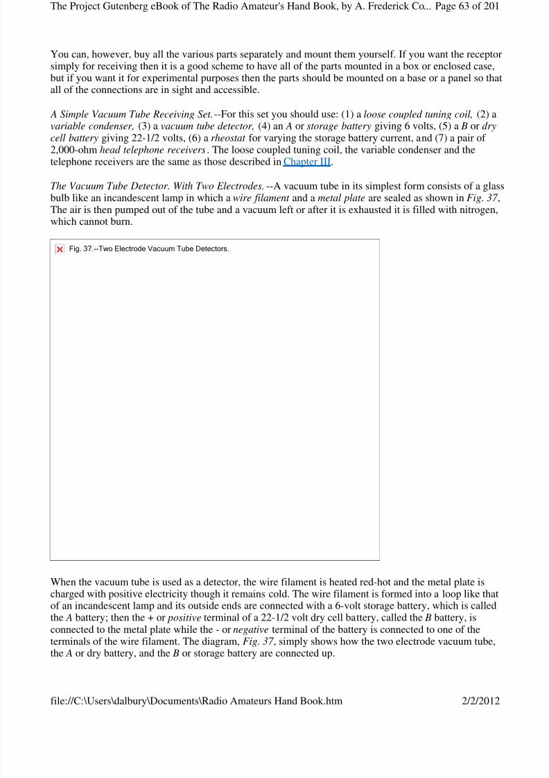
8/3/2019 Radio Amateurs Hand Book
http://slidepdf.com/reader/full/radio-amateurs-hand-book 63/201
You can, however, buy all the various parts separately and mount them yourself. If you want the receptorsimply for receiving then it is a good scheme to have all of the parts mounted in a box or enclosed case,but if you want it for experimental purposes then the parts should be mounted on a base or a panel so thatall of the connections are in sight and accessible.
A Simple Vacuum Tube Receiving Set.--For this set you should use: (1) a loose coupled tuning coil, (2) avariable condenser, (3) a vacuum tube detector, (4) an A or storage battery giving 6 volts, (5) a B or dry
cell battery giving 22-1/2 volts, (6) a rheostat for varying the storage battery current, and (7) a pair of 2,000-ohm head telephone receivers. The loose coupled tuning coil, the variable condenser and thetelephone receivers are the same as those described in Chapter III.
The Vacuum Tube Detector. With Two Electrodes.--A vacuum tube in its simplest form consists of a glassbulb like an incandescent lamp in which a wire filament and a metal plate are sealed as shown in Fig. 37 ,The air is then pumped out of the tube and a vacuum left or after it is exhausted it is filled with nitrogen,which cannot burn.
When the vacuum tube is used as a detector, the wire filament is heated red-hot and the metal plate ischarged with positive electricity though it remains cold. The wire filament is formed into a loop like thatof an incandescent lamp and its outside ends are connected with a 6-volt storage battery, which is calledthe A battery; then the + or positive terminal of a 22-1/2 volt dry cell battery, called the B battery, isconnected to the metal plate while the - or negative terminal of the battery is connected to one of theterminals of the wire filament. The diagram, Fig. 37 , simply shows how the two electrode vacuum tube,the A or dry battery, and the B or storage battery are connected up.
Fig.37.--TwoElectrodeVacuumTubeDetectors.
Page 63 of 201The Project Gutenberg eBook of The Radio Amateur's Hand Book, by A. Frederick Co...
2/2/2012file://C:\Users\dalbury\Documents\Radio Amateurs Hand Book.htm
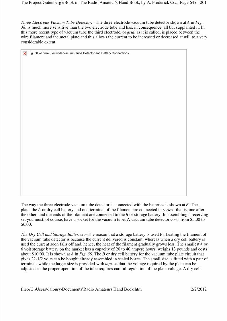
8/3/2019 Radio Amateurs Hand Book
http://slidepdf.com/reader/full/radio-amateurs-hand-book 64/201
Three Electrode Vacuum Tube Detector.--The three electrode vacuum tube detector shown at A in Fig.38, is much more sensitive than the two electrode tube and has, in consequence, all but supplanted it. Inthis more recent type of vacuum tube the third electrode, or grid , as it is called, is placed between thewire filament and the metal plate and this allows the current to be increased or decreased at will to a veryconsiderable extent.
The way the three electrode vacuum tube detector is connected with the batteries is shown at B. Theplate, the A or dry cell battery and one terminal of the filament are connected in series--that is, one afterthe other, and the ends of the filament are connected to the B or storage battery. In assembling a receivingset you must, of course, have a socket for the vacuum tube. A vacuum tube detector costs from $5.00 to
$6.00.
The Dry Cell and Storage Batteries.--The reason that a storage battery is used for heating the filament of the vacuum tube detector is because the current delivered is constant, whereas when a dry cell battery isused the current soon falls off and, hence, the heat of the filament gradually grows less. The smallest A or6 volt storage battery on the market has a capacity of 20 to 40 ampere hours, weighs 13 pounds and costsabout $10.00. It is shown at A in Fig. 39. The B or dry cell battery for the vacuum tube plate circuit thatgives 22-1/2 volts can be bought already assembled in sealed boxes. The small size is fitted with a pair of terminals while the larger size is provided with taps so that the voltage required by the plate can beadjusted as the proper operation of the tube requires careful regulation of the plate voltage. A dry cell
Fig.38.--ThreeElectrodeVacuumTubeDetectorandBatteryConnections.
Page 64 of 201The Project Gutenberg eBook of The Radio Amateur's Hand Book, by A. Frederick Co...
2/2/2012file://C:\Users\dalbury\Documents\Radio Amateurs Hand Book.htm
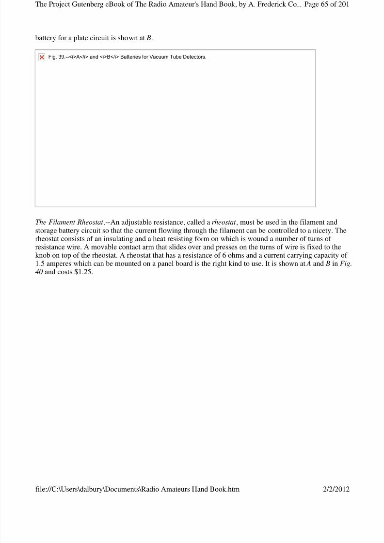
8/3/2019 Radio Amateurs Hand Book
http://slidepdf.com/reader/full/radio-amateurs-hand-book 65/201
battery for a plate circuit is shown at B.
The Filament Rheostat .--An adjustable resistance, called a rheostat , must be used in the filament andstorage battery circuit so that the current flowing through the filament can be controlled to a nicety. Therheostat consists of an insulating and a heat resisting form on which is wound a number of turns of resistance wire. A movable contact arm that slides over and presses on the turns of wire is fixed to theknob on top of the rheostat. A rheostat that has a resistance of 6 ohms and a current carrying capacity of 1.5 amperes which can be mounted on a panel board is the right kind to use. It is shown at A and B in Fig.40 and costs $1.25.
Fig.39.--<i>A</i>and<i>B</i>BatteriesforVacuumTubeDetectors.
Page 65 of 201The Project Gutenberg eBook of The Radio Amateur's Hand Book, by A. Frederick Co...
2/2/2012file://C:\Users\dalbury\Documents\Radio Amateurs Hand Book.htm
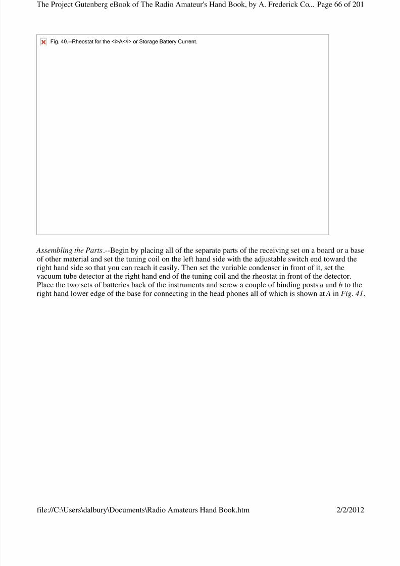
8/3/2019 Radio Amateurs Hand Book
http://slidepdf.com/reader/full/radio-amateurs-hand-book 66/201
Assembling the Parts.--Begin by placing all of the separate parts of the receiving set on a board or a baseof other material and set the tuning coil on the left hand side with the adjustable switch end toward theright hand side so that you can reach it easily. Then set the variable condenser in front of it, set thevacuum tube detector at the right hand end of the tuning coil and the rheostat in front of the detector.Place the two sets of batteries back of the instruments and screw a couple of binding posts a and b to the
right hand lower edge of the base for connecting in the head phones all of which is shown at A in Fig. 41.
Fig.40.--Rheostatforthe<i>A</i>orStorageBatteryCurrent.
Page 66 of 201The Project Gutenberg eBook of The Radio Amateur's Hand Book, by A. Frederick Co...
2/2/2012file://C:\Users\dalbury\Documents\Radio Amateurs Hand Book.htm

8/3/2019 Radio Amateurs Hand Book
http://slidepdf.com/reader/full/radio-amateurs-hand-book 67/201
(A)Fig.41.--TopViewofApparatusLayoutforaVacuumTubeDetectorReceivingSet.
Page 67 of 201The Project Gutenberg eBook of The Radio Amateur's Hand Book, by A. Frederick Co...
2/2/2012file://C:\Users\dalbury\Documents\Radio Amateurs Hand Book.htm
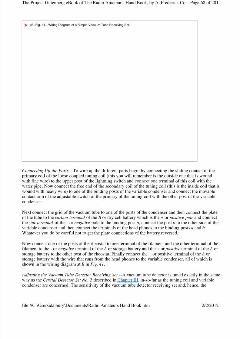
8/3/2019 Radio Amateurs Hand Book
http://slidepdf.com/reader/full/radio-amateurs-hand-book 68/201
Connecting Up the Parts.--To wire up the different parts begin by connecting the sliding contact of the
primary coil of the loose coupled tuning coil (this you will remember is the outside one that is woundwith fine wire) to the upper post of the lightning switch and connect one terminal of this coil with thewater pipe. Now connect the free end of the secondary coil of the tuning coil (this is the inside coil that iswound with heavy wire) to one of the binding posts of the variable condenser and connect the movablecontact arm of the adjustable switch of the primary of the tuning coil with the other post of the variablecondenser.
Next connect the grid of the vacuum tube to one of the posts of the condenser and then connect the plateof the tube to the carbon terminal of the B or dry cell battery which is the + or positive pole and connectthe zinc terminal of the - or negative pole to the binding post a, connect the post b to the other side of thevariable condenser and then connect the terminals of the head phones to the binding posts a and b.Whatever you do be careful not to get the plate connections of the battery reversed.
Now connect one of the posts of the rheostat to one terminal of the filament and the other terminal of thefilament to the - or negative terminal of the A or storage battery and the + or positive terminal of the A orstorage battery to the other post of the rheostat. Finally connect the + or positive terminal of the A orstorage battery with the wire that runs from the head phones to the variable condenser, all of which isshown in the wiring diagram at B in Fig. 41.
Adjusting the Vacuum Tube Detector Receiving Set .--A vacuum tube detector is tuned exactly in the sameway as the Crystal Detector Set No. 2 described in Chapter III, in-so-far as the tuning coil and variablecondenser are concerned. The sensitivity of the vacuum tube detector receiving set and, hence, the
(B)Fig.41.--WiringDiagramofaSimpleVacuumTubeReceivingSet.
Page 68 of 201The Project Gutenberg eBook of The Radio Amateur's Hand Book, by A. Frederick Co...
2/2/2012file://C:\Users\dalbury\Documents\Radio Amateurs Hand Book.htm
8/3/2019 Radio Amateurs Hand Book
http://slidepdf.com/reader/full/radio-amateurs-hand-book 69/201
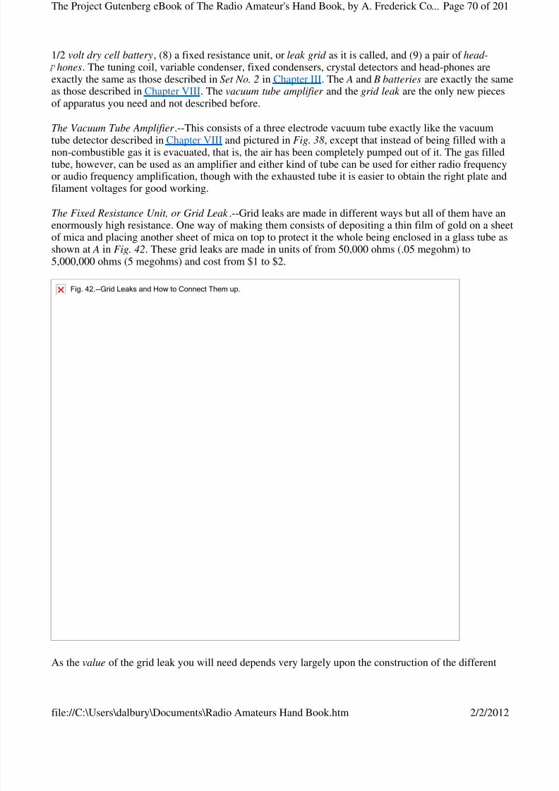
8/3/2019 Radio Amateurs Hand Book
http://slidepdf.com/reader/full/radio-amateurs-hand-book 70/201
1/2 volt dry cell battery, (8) a fixed resistance unit, or leak grid as it is called, and (9) a pair of head-hones. The tuning coil, variable condenser, fixed condensers, crystal detectors and head-phones are
exactly the same as those described in Set No. 2 in Chapter III. The A and B batteries are exactly the sameas those described in Chapter VIII. The vacuum tube amplifier and the grid leak are the only new piecesof apparatus you need and not described before.
The Vacuum Tube Amplifier .--This consists of a three electrode vacuum tube exactly like the vacuum
tube detector described in Chapter VIII and pictured in Fig. 38, except that instead of being filled with anon-combustible gas it is evacuated, that is, the air has been completely pumped out of it. The gas filledtube, however, can be used as an amplifier and either kind of tube can be used for either radio frequencyor audio frequency amplification, though with the exhausted tube it is easier to obtain the right plate andfilament voltages for good working.
The Fixed Resistance Unit, or Grid Leak .--Grid leaks are made in different ways but all of them have anenormously high resistance. One way of making them consists of depositing a thin film of gold on a sheetof mica and placing another sheet of mica on top to protect it the whole being enclosed in a glass tube asshown at A in Fig. 42. These grid leaks are made in units of from 50,000 ohms (.05 megohm) to5,000,000 ohms (5 megohms) and cost from $1 to $2.
As the value of the grid leak you will need depends very largely upon the construction of the different
Fig.42.--GridLeaksandHowtoConnectThemup.
Page 70 of 201The Project Gutenberg eBook of The Radio Amateur's Hand Book, by A. Frederick Co...
2/2/2012file://C:\Users\dalbury\Documents\Radio Amateurs Hand Book.htm
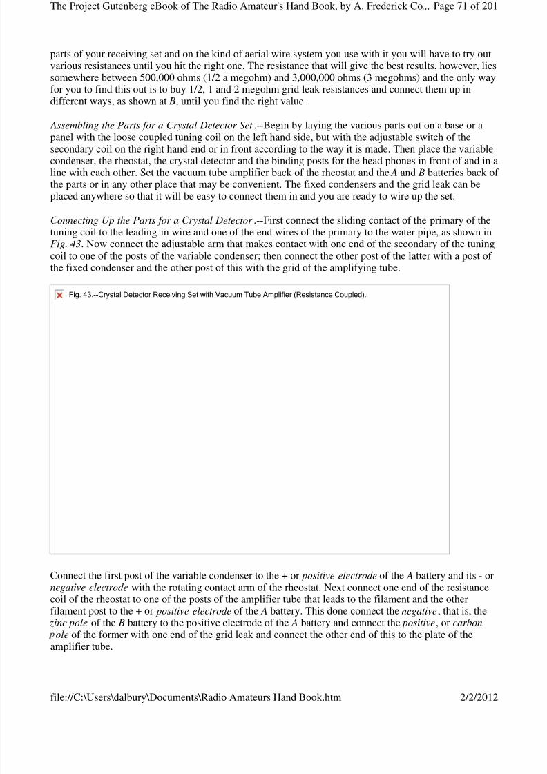
8/3/2019 Radio Amateurs Hand Book
http://slidepdf.com/reader/full/radio-amateurs-hand-book 71/201
parts of your receiving set and on the kind of aerial wire system you use with it you will have to try outvarious resistances until you hit the right one. The resistance that will give the best results, however, liessomewhere between 500,000 ohms (1/2 a megohm) and 3,000,000 ohms (3 megohms) and the only wayfor you to find this out is to buy 1/2, 1 and 2 megohm grid leak resistances and connect them up indifferent ways, as shown at B, until you find the right value.
Assembling the Parts for a Crystal Detector Set .--Begin by laying the various parts out on a base or a
panel with the loose coupled tuning coil on the left hand side, but with the adjustable switch of thesecondary coil on the right hand end or in front according to the way it is made. Then place the variablecondenser, the rheostat, the crystal detector and the binding posts for the head phones in front of and in aline with each other. Set the vacuum tube amplifier back of the rheostat and the A and B batteries back of the parts or in any other place that may be convenient. The fixed condensers and the grid leak can beplaced anywhere so that it will be easy to connect them in and you are ready to wire up the set.
Connecting Up the Parts for a Crystal Detector .--First connect the sliding contact of the primary of thetuning coil to the leading-in wire and one of the end wires of the primary to the water pipe, as shown inFig. 43. Now connect the adjustable arm that makes contact with one end of the secondary of the tuningcoil to one of the posts of the variable condenser; then connect the other post of the latter with a post of
the fixed condenser and the other post of this with the grid of the amplifying tube.
Connect the first post of the variable condenser to the + or positive electrode of the A battery and its - ornegative electrode with the rotating contact arm of the rheostat. Next connect one end of the resistancecoil of the rheostat to one of the posts of the amplifier tube that leads to the filament and the otherfilament post to the + or positive electrode of the A battery. This done connect the negative, that is, the zinc pole of the B battery to the positive electrode of the A battery and connect the positive, or carbon
ole of the former with one end of the grid leak and connect the other end of this to the plate of theamplifier tube.
Fig.43.--CrystalDetectorReceivingSetwithVacuumTubeAmplifier(ResistanceCoupled).
Page 71 of 201The Project Gutenberg eBook of The Radio Amateur's Hand Book, by A. Frederick Co...
2/2/2012file://C:\Users\dalbury\Documents\Radio Amateurs Hand Book.htm
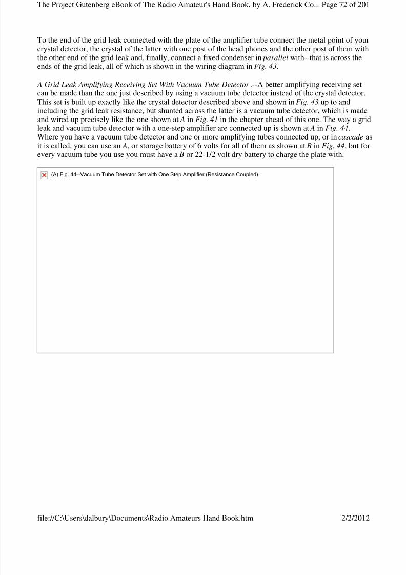
8/3/2019 Radio Amateurs Hand Book
http://slidepdf.com/reader/full/radio-amateurs-hand-book 72/201
To the end of the grid leak connected with the plate of the amplifier tube connect the metal point of yourcrystal detector, the crystal of the latter with one post of the head phones and the other post of them withthe other end of the grid leak and, finally, connect a fixed condenser in parallel with--that is across theends of the grid leak, all of which is shown in the wiring diagram in Fig. 43.
A Grid Leak Amplifying Receiving Set With Vacuum Tube Detector .--A better amplifying receiving setcan be made than the one just described by using a vacuum tube detector instead of the crystal detector.
This set is built up exactly like the crystal detector described above and shown in Fig. 43 up to andincluding the grid leak resistance, but shunted across the latter is a vacuum tube detector, which is madeand wired up precisely like the one shown at A in Fig. 41 in the chapter ahead of this one. The way a gridleak and vacuum tube detector with a one-step amplifier are connected up is shown at A in Fig. 44.Where you have a vacuum tube detector and one or more amplifying tubes connected up, or in cascade asit is called, you can use an A, or storage battery of 6 volts for all of them as shown at B in Fig. 44, but forevery vacuum tube you use you must have a B or 22-1/2 volt dry battery to charge the plate with.
(A)Fig.44--VacuumTubeDetectorSetwithOneStepAmplifier(ResistanceCoupled).
Page 72 of 201The Project Gutenberg eBook of The Radio Amateur's Hand Book, by A. Frederick Co...
2/2/2012file://C:\Users\dalbury\Documents\Radio Amateurs Hand Book.htm
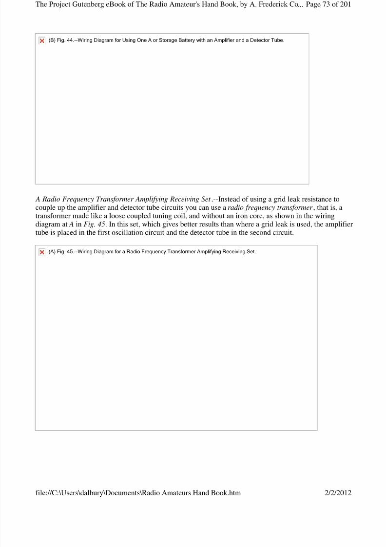
8/3/2019 Radio Amateurs Hand Book
http://slidepdf.com/reader/full/radio-amateurs-hand-book 73/201
A Radio Frequency Transformer Amplifying Receiving Set .--Instead of using a grid leak resistance tocouple up the amplifier and detector tube circuits you can use a radio frequency transformer , that is, atransformer made like a loose coupled tuning coil, and without an iron core, as shown in the wiringdiagram at A in Fig. 45. In this set, which gives better results than where a grid leak is used, the amplifiertube is placed in the first oscillation circuit and the detector tube in the second circuit.
(B)Fig.44.--WiringDiagramforUsingOneAorStorageBatterywithanAmplifierandaDetectorTube.
(A)Fig.45.--WiringDiagramforaRadioFrequencyTransformerAmplifyingReceivingSet.
Page 73 of 201The Project Gutenberg eBook of The Radio Amateur's Hand Book, by A. Frederick Co...
2/2/2012file://C:\Users\dalbury\Documents\Radio Amateurs Hand Book.htm

8/3/2019 Radio Amateurs Hand Book
http://slidepdf.com/reader/full/radio-amateurs-hand-book 74/201
Since the radio frequency transformer has no iron core the high frequency, or radio frequency oscillatingcurrents, as they are called, surge through it and are not changed into low frequency, or audio frequency pulsating currents, until they flow through the detector. Since the diagram shows only one amplifier andone radio frequency transformer, it is consequently a one step amplifier ; however, two, three or more,amplifying tubes can be connected up by means of an equal number of radio frequency transformerswhen you will get wonderful results. Where a six step amplifier, that is, where six amplifying tubes areconnected together, or in cascade, the first three are usually coupled up with radio frequency transformersand the last three with audio frequency transformers. A radio frequency transformer is shown at B andcosts $6 to $7.
An Audio Frequency Transformer Amplifying Receiving Set .--Where audio frequency transformers areused for stepping up the voltage of the current of the detector and amplifier tubes, the radio frequencycurrent does not get into the plate circuit of the detector at all for the reason that the iron core of thetransformer chokes them off, hence, the succeeding amplifiers operate at audio frequencies. An audiofrequency transformer is shown at A in Fig. 46 and a wiring diagram showing how the tubes areconnected in cascade with the transformers is shown at B; it is therefore a two-step audio frequencyreceiving set.
(B)Fig.45.--RadioFrequencyTransformer.
Page 74 of 201The Project Gutenberg eBook of The Radio Amateur's Hand Book, by A. Frederick Co...
2/2/2012file://C:\Users\dalbury\Documents\Radio Amateurs Hand Book.htm
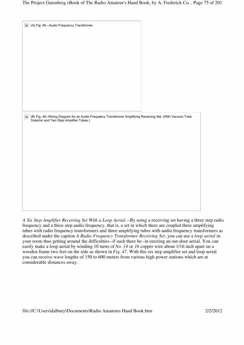
8/3/2019 Radio Amateurs Hand Book
http://slidepdf.com/reader/full/radio-amateurs-hand-book 75/201
A Six Step Amplifier Receiving Set With a Loop Aerial.--By using a receiving set having a three step radiofrequency and a three step audio frequency, that is, a set in which there are coupled three amplifyingtubes with radio frequency transformers and three amplifying tubes with audio frequency transformers asdescribed under the caption A Radio Frequency Transformer Receiving Set , you can use a loop aerial in
your room thus getting around the difficulties--if such there be--in erecting an out-door aerial. You caneasily make a loop aerial by winding 10 turns of No. 14 or 16 copper wire about 1/16 inch apart on awooden frame two feet on the side as shown in Fig. 47 . With this six step amplifier set and loop aerialyou can receive wave lengths of 150 to 600 meters from various high power stations which are atconsiderable distances away.
(A)Fig.46.--AudioFrequencyTransformer.
(B)Fig.46--WiringDiagramforanAudioFrequencyTransformerAmplifyingReceivingSet.(WithVacuumTube
DetectorandTwoStepAmplifierTubes.)
Page 75 of 201The Project Gutenberg eBook of The Radio Amateur's Hand Book, by A. Frederick Co...
2/2/2012file://C:\Users\dalbury\Documents\Radio Amateurs Hand Book.htm
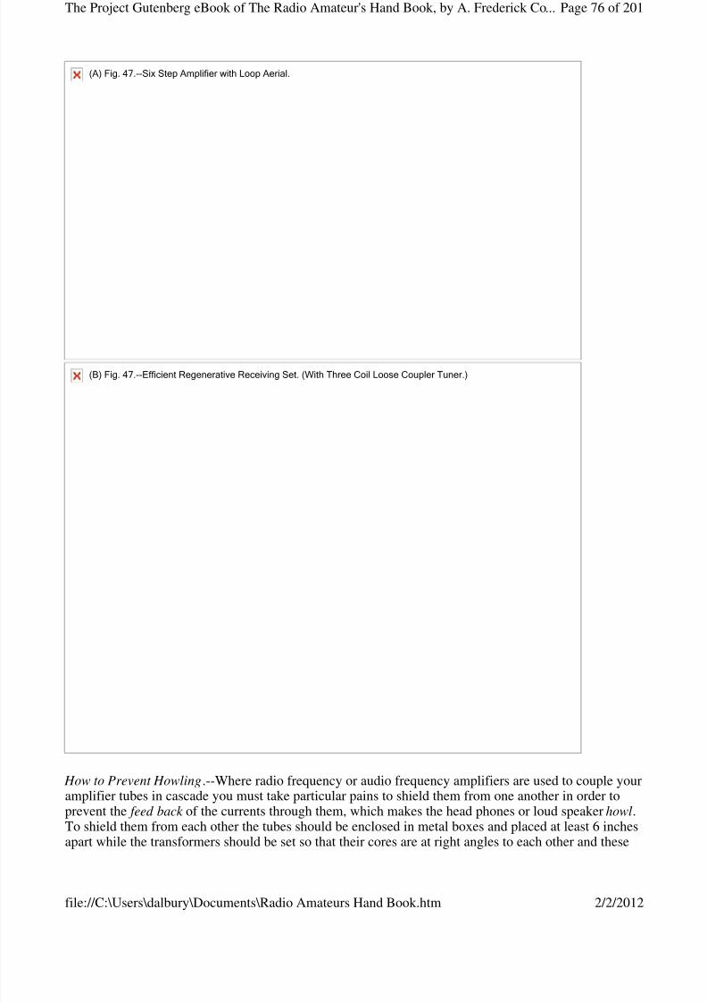
8/3/2019 Radio Amateurs Hand Book
http://slidepdf.com/reader/full/radio-amateurs-hand-book 76/201
How to Prevent Howling.--Where radio frequency or audio frequency amplifiers are used to couple youramplifier tubes in cascade you must take particular pains to shield them from one another in order toprevent the feed back of the currents through them, which makes the head phones or loud speaker howl.To shield them from each other the tubes should be enclosed in metal boxes and placed at least 6 inchesapart while the transformers should be set so that their cores are at right angles to each other and these
(A)Fig.47.--SixStepAmplifierwithLoopAerial.
(B)Fig.47.--EfficientRegenerativeReceivingSet.(WithThreeCoilLooseCouplerTuner.)
Page 76 of 201The Project Gutenberg eBook of The Radio Amateur's Hand Book, by A. Frederick Co...
2/2/2012file://C:\Users\dalbury\Documents\Radio Amateurs Hand Book.htm
8/3/2019 Radio Amateurs Hand Book
http://slidepdf.com/reader/full/radio-amateurs-hand-book 77/201
also should be not less than six inches apart.
CHAPTER X
REGENERATIVE AMPLIFICATION RECEIVING SETS
While a vacuum tube detector has an amplifying action of its own, and this accounts for its greatsensitiveness, its amplifying action can be further increased to an enormous extent by making the radiofrequency currents that are set up in the oscillation circuits react on the detector.
Such currents are called feed-back or regenerative currents and when circuits are so arranged as to causethe currents to flow back through the detector tube the amplification keeps on increasing until thecapacity of the tube itself is reached. It is like using steam over and over again in a steam turbine untilthere is no more energy left in it. A system of circuits which will cause this regenerative action to takeplace is known as the Armstrong circuits and is so called after the young man who discovered it.
Since the regenerative action of the radio frequency currents is produced by the detector tube itself andwhich sets up an amplifying effect without the addition of an amplifying tube, this type of receiving sethas found great favor with amateurs, while in combination with amplifying tubes it multiplies their powerproportionately and it is in consequence used in one form or another in all the better sets.
There are many different kinds of circuits which can be used to produce the regenerative amplificationeffect while the various kinds of tuning coils will serve for coupling them; for instance a two or threeslide single tuning coil will answer the purpose but as it does not give good results it is not advisable tospend either time or money on it. A better scheme is to use a loose coupler formed of two or threehoneycomb or other compact coils, while a variocoupler or a variometer or two will produce themaximum regenerative action.
The Simplest Type of Regenerative Receiving Set. With Loose Coupled Tuning Coil.--While this
regenerative set is the simplest that will give anything like fair results it is here described not on accountof its desirability, but because it will serve to give you the fundamental idea of how the feed-back circuitis formed.
For this set you need: (1) a loose-coupled tuning coil such as described in Chapter III, (2) a variablecondenser of .001 mfd. (microfarad) capacitance; (3) one fixed condenser of .001 mfd.; (4) one fixed condenser for the grid leak circuit of .00025 mfd.; (5) a grid leak of 1/2 to 2 megohms resistance; (6) avacuum tube detector ; (7) an A 6 volt battery; (8) a rheostat ; (9) a B 22 1/2 volt battery; and (10) a pair of 2000 ohm head phones.
Connecting Up the Parts.--Begin by connecting the leading-in wire of the aerial with the binding post end
of the primary coil of the loose coupler as shown in the wiring diagram Fig. 48 and then connect thesliding contact with the water pipe or other ground. Connect the binding post end of the primary coil withone post of the variable condenser, connect the other post of this with one of the posts of the .00025 mfd. condenser and the other end of this with the grid of the detector tube; then around this condenser shuntthe grid leak resistance.
Page 77 of 201The Project Gutenberg eBook of The Radio Amateur's Hand Book, by A. Frederick Co...
2/2/2012file://C:\Users\dalbury\Documents\Radio Amateurs Hand Book.htm
8/3/2019 Radio Amateurs Hand Book
http://slidepdf.com/reader/full/radio-amateurs-hand-book 78/201
Next connect the sliding contact of the primary coil with the other post of the variable condenser andfrom this lead a wire on over to one of the terminals of the filament of the vacuum tube; to the otherterminal of the filament connect one of the posts of the rheostat and connect the other post to the - ornegative electrode of the A battery and then connect the + or positive electrode of it to the other terminalof the filament.
Connect the + or positive electrode of the A battery with one post of the .001 mfd. fixed condenser andconnect the other post of this to one of the ends of the secondary coil of the tuning coil and which is nowknown as the tickler coil; then connect the other end of the secondary, or tickler coil to the plate of thevacuum tube. In the wiring diagram the secondary, or tickler coil is shown above and in a line with theprimary coil but this is only for the sake of making the connections clear; in reality the secondary, or
tickler coil slides to and fro in the primary coil as shown and described in Chapter III. Finally connect thenegative, or zinc pole of the B battery to one side of the fixed condenser, the positive, or carbon, pole toone of the terminals of the head phones and the other terminal of this to the other post of the fixedcondenser when your regenerative set is complete.
An Efficient Regenerative Receiving Set. With Three Coil Loose Coupler.--To construct a really goodregenerative set you must use a loose coupled tuner that has three coils, namely a primary, a secondary and a tickler coil. A tuner of this kind is made like an ordinary loose coupled tuning coil but it has a third coil as shown at A and B in Fig. 49. The middle coil, which is the secondary, is fixed to the base, and thelarge outside coil, which is the primary, is movable, that is it slides to and fro over the middle coil, while
Fig.48.--SimpleRegenerativeReceivingSet.(WithLooseCouplerTuner.)
Page 78 of 201The Project Gutenberg eBook of The Radio Amateur's Hand Book, by A. Frederick Co...
2/2/2012file://C:\Users\dalbury\Documents\Radio Amateurs Hand Book.htm
8/3/2019 Radio Amateurs Hand Book
http://slidepdf.com/reader/full/radio-amateurs-hand-book 79/201
the small inside coil, which is the tickler , is also movable and can slide in or out of the middle coil. Noneof these coils is variable; all are wound to receive waves up to 360 meters in length when used with avariable condenser of .001 mfd . capacitance. In other words you slide the coils in and out to get the rightamount of coupling and you tune by adjusting the variable condenser to get the exact wave length youwant.
With Compact Coils.--Compact coil tuners are formed of three fixed inductances wound in flat coils, andthese are pivoted in a mounting so that the distance between them and, therefore, the coupling, can bevaried, as shown at A in Fig. 50. These coils are wound up by the makers for various wave lengthsranging from a small one that will receive waves of any length up to 360 meters to a large one that has amaximum of 24,000 meters. For an amateur set get three of the smallest coils when you can not only hearamateur stations that send on a 200 meter wave but broadcasting stations that send on a 360 meter wave.
(A)Fig.49.--DiagramofaThreeCoilCoupler.
(B)Fig.49.--ThreeCoilLooseCouplerTuner.
Page 79 of 201The Project Gutenberg eBook of The Radio Amateur's Hand Book, by A. Frederick Co...
2/2/2012file://C:\Users\dalbury\Documents\Radio Amateurs Hand Book.htm
8/3/2019 Radio Amateurs Hand Book
http://slidepdf.com/reader/full/radio-amateurs-hand-book 80/201
These three coils are mounted with panel plugs which latter fit into a stand, or mounting, so that themiddle coil is fixed, that is, stationary, while the two outside coils can be swung to and fro like a door;this scheme permits small variations of coupling to be had between the coils and this can be done eitherby handles or by means of knobs on a panel board. While I have suggested the use of the smallest sizecoils, you can get and use those wound for any wave length you want to receive and when those areconnected with variometers and variable condensers, and with a proper aerial, you will have a highlyefficient receptor that will work over all ranges of wave lengths. The smallest size coils cost about $1.50apiece and the mounting costs about $6 or $7 each.
The A Battery Potentiometer .--This device is simply a resistance like the rheostat described in connectionwith the preceding vacuum tube receiving sets but it is wound to 200 or 300 ohms resistance as against 1-1/2 to 6 ohms of the rheostat. It is, however, used as well as the rheostat. With a vacuum tube detector,and especially with one having a gas-content, a potentiometer is very necessary as it is only by means of it that the potential of the plate of the detector can be accurately regulated. The result of proper regulationis that when the critical potential value is reached there is a marked increase in the loudness of the soundsthat are emitted by the head phones.
As you will see from A in Fig. 51 it has three taps. The two taps which are connected with the ends of theresistance coil are shunted around the A battery and the third tap, which is attached to the movablecontact arm, is connected with the B battery tap, see B, at which this battery gives 18 volts. Since the A battery gives 6 volts you can vary the potential of the plate from 18 to 24 volts. The potentiometer mustnever be shunted around the B battery or the latter will soon run down. A potentiometer costs a couple of
dollars.
Fig.50.--HoneycombInductanceCoil.
Page 80 of 201The Project Gutenberg eBook of The Radio Amateur's Hand Book, by A. Frederick Co...
2/2/2012file://C:\Users\dalbury\Documents\Radio Amateurs Hand Book.htm
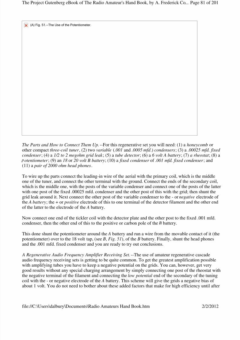
8/3/2019 Radio Amateurs Hand Book
http://slidepdf.com/reader/full/radio-amateurs-hand-book 81/201
The Parts and How to Connect Them Up.--For this regenerative set you will need: (1) a honeycomb orother compact three-coil tuner , (2) two variable (.001 and .0005 mfd .) condensers; (3) a .00025 mfd. fixed condenser ; (4) a 1/2 to 2 megohm grid leak ; (5) a tube detector ; (6) a 6 volt A battery; (7) a rheostat ; (8) a
otentiometer ; (9) an 18 or 20 volt B battery; (10) a fixed condenser of .001 mfd. fixed condenser ; and(11) a pair of 2000 ohm head phones.
To wire up the parts connect the leading-in wire of the aerial with the primary coil, which is the middleone of the tuner, and connect the other terminal with the ground. Connect the ends of the secondary coil,which is the middle one, with the posts of the variable condenser and connect one of the posts of the latterwith one post of the fixed .00025 mfd. condenser and the other post of this with the grid; then shunt thegrid leak around it. Next connect the other post of the variable condenser to the - or negative electrode of the A battery; the + or positive electrode of this to one terminal of the detector filament and the other endof the latter to the electrode of the A battery.
Now connect one end of the tickler coil with the detector plate and the other post to the fixed .001 mfd.condenser, then the other end of this to the positive or carbon pole of the B battery.
This done shunt the potentiometer around the A battery and run a wire from the movable contact of it (the
potentiometer) over to the 18 volt tap, (see B, Fig. 51), of the B battery. Finally, shunt the head phonesand the .001 mfd. fixed condenser and you are ready to try out conclusions.
A Regenerative Audio Frequency Amplifier Receiving Set.--The use of amateur regenerative cascadeaudio frequency receiving sets is getting to be quite common. To get the greatest amplification possiblewith amplifying tubes you have to keep a negative potential on the grids. You can, however, get verygood results without any special charging arrangement by simply connecting one post of the rheostat withthe negative terminal of the filament and connecting the low potential end of the secondary of the tuningcoil with the - or negative electrode of the A battery. This scheme will give the grids a negative bias of about 1 volt. You do not need to bother about these added factors that make for high efficiency until after
(A)Fig.51.--TheUseofthePotentiometer.
Page 81 of 201The Project Gutenberg eBook of The Radio Amateur's Hand Book, by A. Frederick Co...
2/2/2012file://C:\Users\dalbury\Documents\Radio Amateurs Hand Book.htm

8/3/2019 Radio Amateurs Hand Book
http://slidepdf.com/reader/full/radio-amateurs-hand-book 82/201
you have got your receiving set in working order and understand all about it.
The Parts and How to Connect Them Up.--Exactly the same parts are needed for this set as the onedescribed above, but in addition you will want: (1) two more rheostats; (2) two more sets of B 22-1/2 volt batteries; (3) two amplifier tubes, and (4) two audio frequency transformers as described in Chapter IX and pictured at A in Fig. 46 .
To wire up the parts begin by connecting the leading-in wire to one end of the primary of the tuning coiland then connect the other end of the coil with the ground. A variable condenser of .001 mfd. capacitancecan be connected in the ground wire, as shown in Fig. 52, to good advantage although it is not absolutelyneeded. Now connect one end of the secondary coil to one post of a .001 mfd. variable condenser and theother end of the secondary to the other post of the condenser.
Next bring a lead (wire) from the first post of the variable condenser over to the post of the first fixedcondenser and connect the other post of the latter with the grid of the detector tube. Shunt 1/2 to 2megohm grid leak resistance around the fixed condenser and then connect the second post of the variablecondenser to one terminal of the detector tube filament. Run this wire on over and connect it with the firstpost of the second rheostat, the second post of which is connected with one terminal of the filament of thefirst amplifying tube; then connect the first post of the rheostat with one end of the secondary coil of thefirst audio frequency transformer, and the other end of this coil with the grid of the first amplifier tube.
Connect the lead that runs from the second post of variable condenser to the first post of the thirdrheostat, the second post of which is connected with one terminal of the second amplifying tube; thenconnect the first post of the rheostat with one end of the secondary coil of the second audio frequencytransformer and the other end of this coil with the grid of the second amplifier tube.
This done connect the - or negative electrode of the A battery with the second post of the variablecondenser and connect the + or positive electrode with the free post of the first rheostat, the other post of which connects with the free terminal of the filament of the detector. From this lead tap off a wire andconnect it to the free terminal of the filament of the first amplifier tube, and finally connect the end of the
Fig.52.--RegenerativeAudioFrequencyAmplifierReceivingSet.
Page 82 of 201The Project Gutenberg eBook of The Radio Amateur's Hand Book, by A. Frederick Co...
2/2/2012file://C:\Users\dalbury\Documents\Radio Amateurs Hand Book.htm
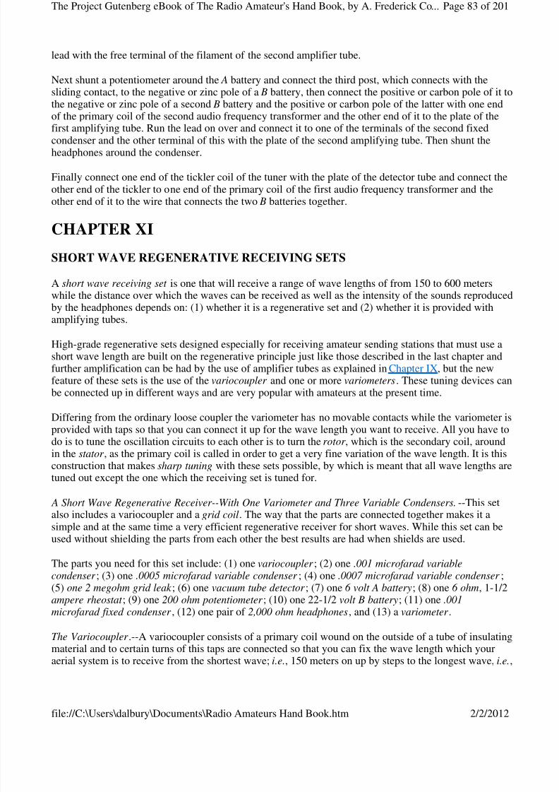
8/3/2019 Radio Amateurs Hand Book
http://slidepdf.com/reader/full/radio-amateurs-hand-book 83/201
lead with the free terminal of the filament of the second amplifier tube.
Next shunt a potentiometer around the A battery and connect the third post, which connects with thesliding contact, to the negative or zinc pole of a B battery, then connect the positive or carbon pole of it tothe negative or zinc pole of a second B battery and the positive or carbon pole of the latter with one endof the primary coil of the second audio frequency transformer and the other end of it to the plate of thefirst amplifying tube. Run the lead on over and connect it to one of the terminals of the second fixed
condenser and the other terminal of this with the plate of the second amplifying tube. Then shunt theheadphones around the condenser.
Finally connect one end of the tickler coil of the tuner with the plate of the detector tube and connect theother end of the tickler to one end of the primary coil of the first audio frequency transformer and theother end of it to the wire that connects the two B batteries together.
CHAPTER XI
SHORT WAVE REGENERATIVE RECEIVING SETS
A short wave receiving set is one that will receive a range of wave lengths of from 150 to 600 meterswhile the distance over which the waves can be received as well as the intensity of the sounds reproducedby the headphones depends on: (1) whether it is a regenerative set and (2) whether it is provided withamplifying tubes.
High-grade regenerative sets designed especially for receiving amateur sending stations that must use ashort wave length are built on the regenerative principle just like those described in the last chapter andfurther amplification can be had by the use of amplifier tubes as explained in Chapter IX, but the newfeature of these sets is the use of the variocoupler and one or more variometers. These tuning devices canbe connected up in different ways and are very popular with amateurs at the present time.
Differing from the ordinary loose coupler the variometer has no movable contacts while the variometer isprovided with taps so that you can connect it up for the wave length you want to receive. All you have todo is to tune the oscillation circuits to each other is to turn the rotor , which is the secondary coil, aroundin the stator , as the primary coil is called in order to get a very fine variation of the wave length. It is thisconstruction that makes sharp tuning with these sets possible, by which is meant that all wave lengths aretuned out except the one which the receiving set is tuned for.
A Short Wave Regenerative Receiver--With One Variometer and Three Variable Condensers.--This setalso includes a variocoupler and a grid coil. The way that the parts are connected together makes it asimple and at the same time a very efficient regenerative receiver for short waves. While this set can beused without shielding the parts from each other the best results are had when shields are used.
The parts you need for this set include: (1) one variocoupler ; (2) one .001 microfarad variablecondenser ; (3) one .0005 microfarad variable condenser ; (4) one .0007 microfarad variable condenser ;(5) one 2 megohm grid leak ; (6) one vacuum tube detector ; (7) one 6 volt A battery; (8) one 6 ohm, 1-1/2ampere rheostat ; (9) one 200 ohm potentiometer ; (10) one 22-1/2 volt B battery; (11) one .001microfarad fixed condenser , (12) one pair of 2,000 ohm headphones, and (13) a variometer .
The Variocoupler .--A variocoupler consists of a primary coil wound on the outside of a tube of insulatingmaterial and to certain turns of this taps are connected so that you can fix the wave length which youraerial system is to receive from the shortest wave; i.e., 150 meters on up by steps to the longest wave, i.e.,
Page 83 of 201The Project Gutenberg eBook of The Radio Amateur's Hand Book, by A. Frederick Co...
2/2/2012file://C:\Users\dalbury\Documents\Radio Amateurs Hand Book.htm
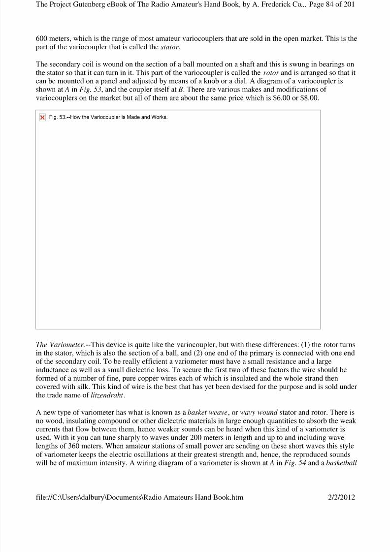
8/3/2019 Radio Amateurs Hand Book
http://slidepdf.com/reader/full/radio-amateurs-hand-book 84/201
600 meters, which is the range of most amateur variocouplers that are sold in the open market. This is thepart of the variocoupler that is called the stator .
The secondary coil is wound on the section of a ball mounted on a shaft and this is swung in bearings onthe stator so that it can turn in it. This part of the variocoupler is called the rotor and is arranged so that itcan be mounted on a panel and adjusted by means of a knob or a dial. A diagram of a variocoupler isshown at A in Fig. 53, and the coupler itself at B. There are various makes and modifications of
variocouplers on the market but all of them are about the same price which is $6.00 or $8.00.
The Variometer.--This device is quite like the variocoupler, but with these differences: (1) the rotor turnsin the stator, which is also the section of a ball, and (2) one end of the primary is connected with one endof the secondary coil. To be really efficient a variometer must have a small resistance and a largeinductance as well as a small dielectric loss. To secure the first two of these factors the wire should beformed of a number of fine, pure copper wires each of which is insulated and the whole strand then
covered with silk. This kind of wire is the best that has yet been devised for the purpose and is sold underthe trade name of litzendraht .
A new type of variometer has what is known as a basket weave, or wavy wound stator and rotor. There isno wood, insulating compound or other dielectric materials in large enough quantities to absorb the weak currents that flow between them, hence weaker sounds can be heard when this kind of a variometer isused. With it you can tune sharply to waves under 200 meters in length and up to and including wavelengths of 360 meters. When amateur stations of small power are sending on these short waves this styleof variometer keeps the electric oscillations at their greatest strength and, hence, the reproduced soundswill be of maximum intensity. A wiring diagram of a variometer is shown at A in Fig. 54 and a basketball
Fig.53.--HowtheVariocouplerisMadeandWorks.
Page 84 of 201The Project Gutenberg eBook of The Radio Amateur's Hand Book, by A. Frederick Co...
2/2/2012file://C:\Users\dalbury\Documents\Radio Amateurs Hand Book.htm
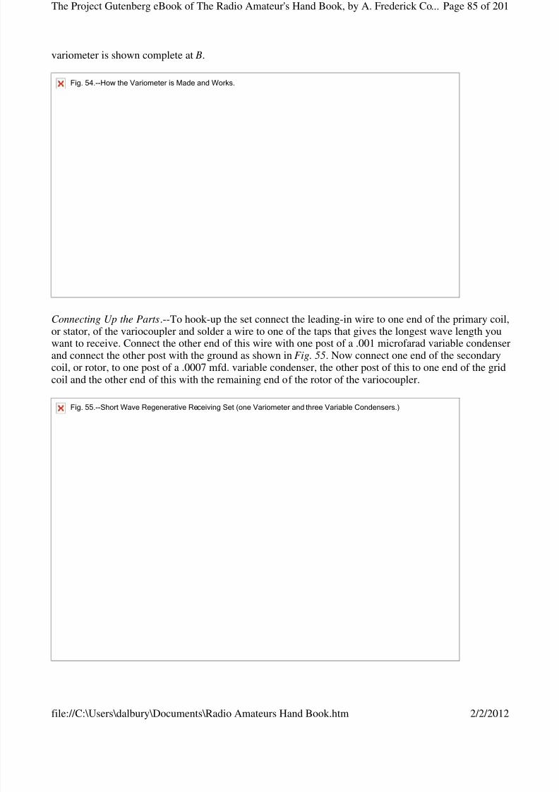
8/3/2019 Radio Amateurs Hand Book
http://slidepdf.com/reader/full/radio-amateurs-hand-book 85/201
variometer is shown complete at B.
Connecting Up the Parts.--To hook-up the set connect the leading-in wire to one end of the primary coil,or stator, of the variocoupler and solder a wire to one of the taps that gives the longest wave length youwant to receive. Connect the other end of this wire with one post of a .001 microfarad variable condenserand connect the other post with the ground as shown in Fig. 55. Now connect one end of the secondarycoil, or rotor, to one post of a .0007 mfd. variable condenser, the other post of this to one end of the gridcoil and the other end of this with the remaining end of the rotor of the variocoupler.
Fig.54.--HowtheVariometerisMadeandWorks.
Fig.55.--ShortWaveRegenerativeReceivingSet(oneVariometerandthreeVariableCondensers.)
Page 85 of 201The Project Gutenberg eBook of The Radio Amateur's Hand Book, by A. Frederick Co...
2/2/2012file://C:\Users\dalbury\Documents\Radio Amateurs Hand Book.htm
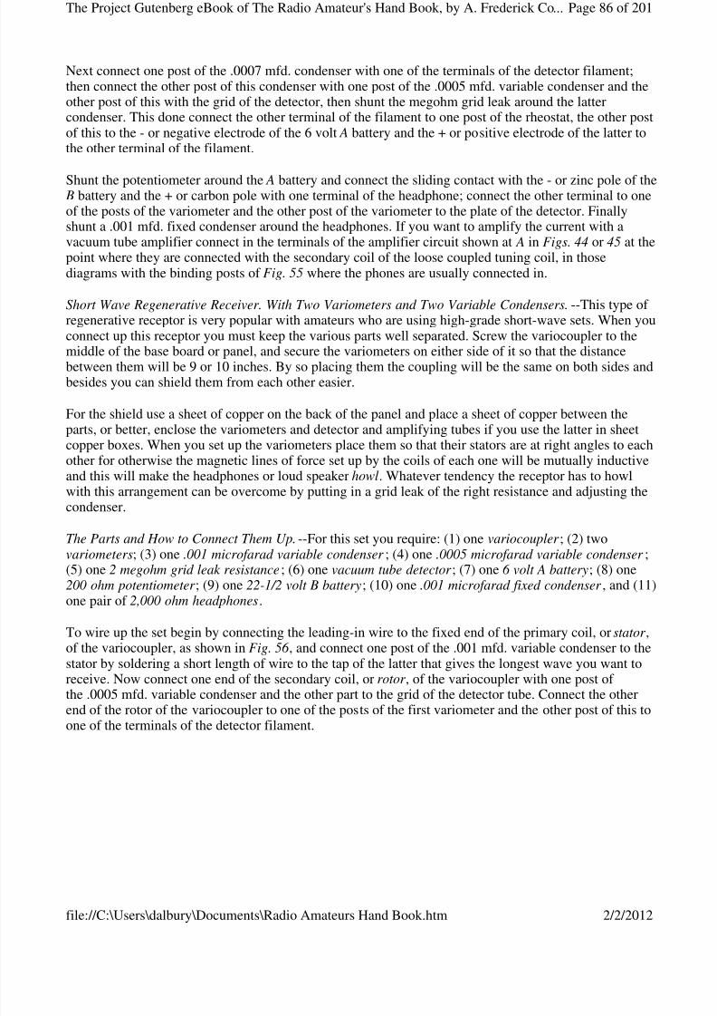
8/3/2019 Radio Amateurs Hand Book
http://slidepdf.com/reader/full/radio-amateurs-hand-book 86/201
Next connect one post of the .0007 mfd. condenser with one of the terminals of the detector filament;then connect the other post of this condenser with one post of the .0005 mfd. variable condenser and theother post of this with the grid of the detector, then shunt the megohm grid leak around the lattercondenser. This done connect the other terminal of the filament to one post of the rheostat, the other postof this to the - or negative electrode of the 6 volt A battery and the + or positive electrode of the latter tothe other terminal of the filament.
Shunt the potentiometer around the A battery and connect the sliding contact with the - or zinc pole of the B battery and the + or carbon pole with one terminal of the headphone; connect the other terminal to oneof the posts of the variometer and the other post of the variometer to the plate of the detector. Finallyshunt a .001 mfd. fixed condenser around the headphones. If you want to amplify the current with avacuum tube amplifier connect in the terminals of the amplifier circuit shown at A in Figs. 44 or 45 at thepoint where they are connected with the secondary coil of the loose coupled tuning coil, in thosediagrams with the binding posts of Fig. 55 where the phones are usually connected in.
Short Wave Regenerative Receiver. With Two Variometers and Two Variable Condensers.--This type of regenerative receptor is very popular with amateurs who are using high-grade short-wave sets. When youconnect up this receptor you must keep the various parts well separated. Screw the variocoupler to the
middle of the base board or panel, and secure the variometers on either side of it so that the distancebetween them will be 9 or 10 inches. By so placing them the coupling will be the same on both sides andbesides you can shield them from each other easier.
For the shield use a sheet of copper on the back of the panel and place a sheet of copper between theparts, or better, enclose the variometers and detector and amplifying tubes if you use the latter in sheetcopper boxes. When you set up the variometers place them so that their stators are at right angles to eachother for otherwise the magnetic lines of force set up by the coils of each one will be mutually inductiveand this will make the headphones or loud speaker howl. Whatever tendency the receptor has to howlwith this arrangement can be overcome by putting in a grid leak of the right resistance and adjusting thecondenser.
The Parts and How to Connect Them Up.--For this set you require: (1) one variocoupler ; (2) twovariometers; (3) one .001 microfarad variable condenser ; (4) one .0005 microfarad variable condenser ;(5) one 2 megohm grid leak resistance; (6) one vacuum tube detector ; (7) one 6 volt A battery; (8) one200 ohm potentiometer ; (9) one 22-1/2 volt B battery; (10) one .001 microfarad fixed condenser , and (11)one pair of 2,000 ohm headphones.
To wire up the set begin by connecting the leading-in wire to the fixed end of the primary coil, or stator ,of the variocoupler, as shown in Fig. 56 , and connect one post of the .001 mfd. variable condenser to thestator by soldering a short length of wire to the tap of the latter that gives the longest wave you want toreceive. Now connect one end of the secondary coil, or rotor , of the variocoupler with one post of the .0005 mfd. variable condenser and the other part to the grid of the detector tube. Connect the other
end of the rotor of the variocoupler to one of the posts of the first variometer and the other post of this toone of the terminals of the detector filament.
Page 86 of 201The Project Gutenberg eBook of The Radio Amateur's Hand Book, by A. Frederick Co...
2/2/2012file://C:\Users\dalbury\Documents\Radio Amateurs Hand Book.htm
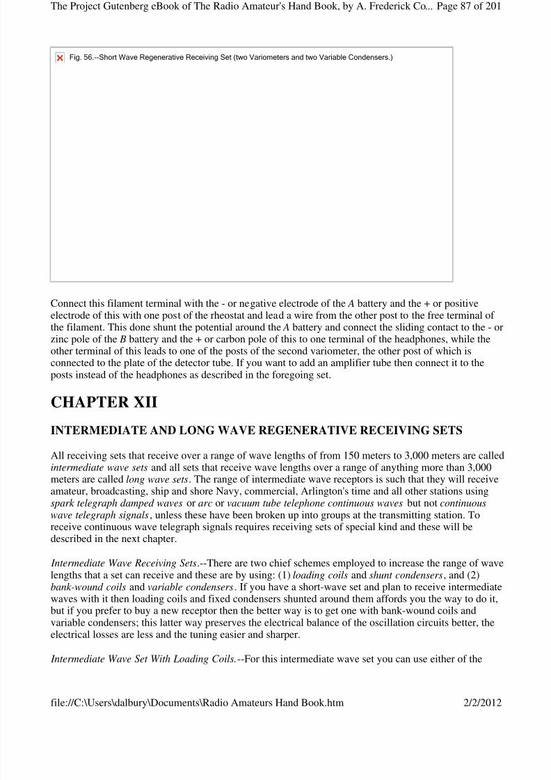
8/3/2019 Radio Amateurs Hand Book
http://slidepdf.com/reader/full/radio-amateurs-hand-book 87/201
Connect this filament terminal with the - or negative electrode of the A battery and the + or positiveelectrode of this with one post of the rheostat and lead a wire from the other post to the free terminal of the filament. This done shunt the potential around the A battery and connect the sliding contact to the - orzinc pole of the B battery and the + or carbon pole of this to one terminal of the headphones, while theother terminal of this leads to one of the posts of the second variometer, the other post of which isconnected to the plate of the detector tube. If you want to add an amplifier tube then connect it to theposts instead of the headphones as described in the foregoing set.
CHAPTER XIIINTERMEDIATE AND LONG WAVE REGENERATIVE RECEIVING SETS
All receiving sets that receive over a range of wave lengths of from 150 meters to 3,000 meters are calledintermediate wave sets and all sets that receive wave lengths over a range of anything more than 3,000meters are called long wave sets. The range of intermediate wave receptors is such that they will receiveamateur, broadcasting, ship and shore Navy, commercial, Arlington's time and all other stations usingspark telegraph damped waves or arc or vacuum tube telephone continuous waves but not continuouswave telegraph signals, unless these have been broken up into groups at the transmitting station. Toreceive continuous wave telegraph signals requires receiving sets of special kind and these will bedescribed in the next chapter.
Intermediate Wave Receiving Sets.--There are two chief schemes employed to increase the range of wavelengths that a set can receive and these are by using: (1) loading coils and shunt condensers, and (2)bank-wound coils and variable condensers. If you have a short-wave set and plan to receive intermediatewaves with it then loading coils and fixed condensers shunted around them affords you the way to do it,but if you prefer to buy a new receptor then the better way is to get one with bank-wound coils andvariable condensers; this latter way preserves the electrical balance of the oscillation circuits better, theelectrical losses are less and the tuning easier and sharper.
Intermediate Wave Set With Loading Coils.--For this intermediate wave set you can use either of the
Fig.56.--ShortWaveRegenerativeReceivingSet(twoVariometersandtwoVariableCondensers.)
Page 87 of 201The Project Gutenberg eBook of The Radio Amateur's Hand Book, by A. Frederick Co...
2/2/2012file://C:\Users\dalbury\Documents\Radio Amateurs Hand Book.htm
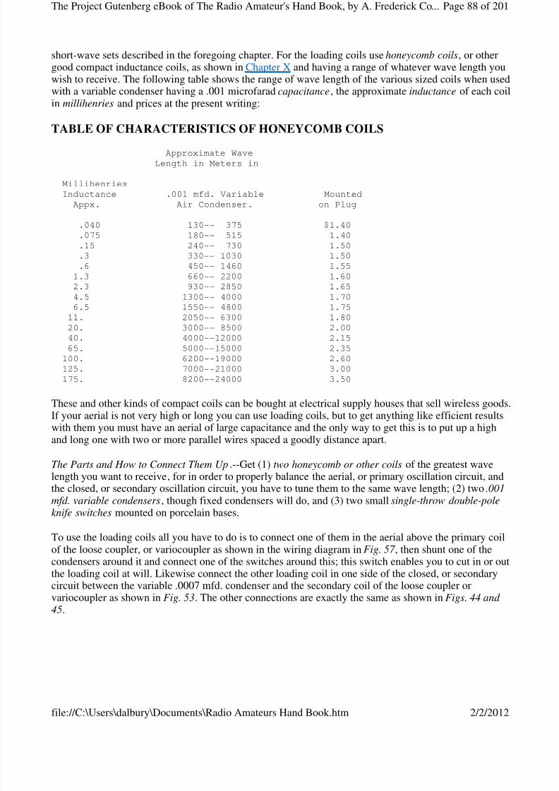
8/3/2019 Radio Amateurs Hand Book
http://slidepdf.com/reader/full/radio-amateurs-hand-book 88/201
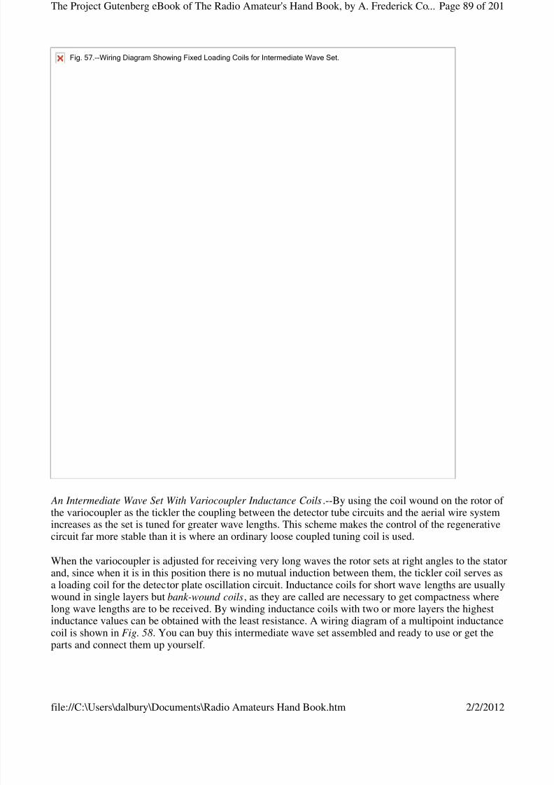
8/3/2019 Radio Amateurs Hand Book
http://slidepdf.com/reader/full/radio-amateurs-hand-book 89/201
An Intermediate Wave Set With Variocoupler Inductance Coils.--By using the coil wound on the rotor of the variocoupler as the tickler the coupling between the detector tube circuits and the aerial wire systemincreases as the set is tuned for greater wave lengths. This scheme makes the control of the regenerativecircuit far more stable than it is where an ordinary loose coupled tuning coil is used.
When the variocoupler is adjusted for receiving very long waves the rotor sets at right angles to the statorand, since when it is in this position there is no mutual induction between them, the tickler coil serves asa loading coil for the detector plate oscillation circuit. Inductance coils for short wave lengths are usuallywound in single layers but bank-wound coils, as they are called are necessary to get compactness wherelong wave lengths are to be received. By winding inductance coils with two or more layers the highestinductance values can be obtained with the least resistance. A wiring diagram of a multipoint inductancecoil is shown in Fig. 58. You can buy this intermediate wave set assembled and ready to use or get theparts and connect them up yourself.
Fig.57.--WiringDiagramShowingFixedLoadingCoilsforIntermediateWaveSet.
Page 89 of 201The Project Gutenberg eBook of The Radio Amateur's Hand Book, by A. Frederick Co...
2/2/2012file://C:\Users\dalbury\Documents\Radio Amateurs Hand Book.htm
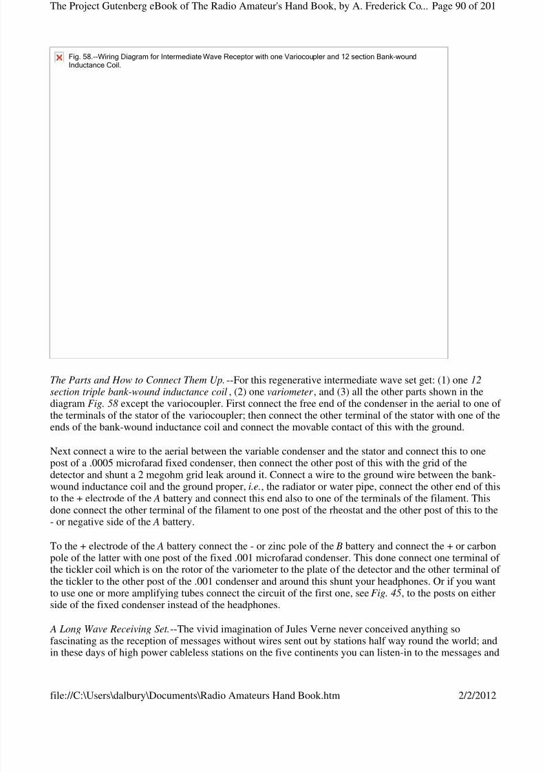
8/3/2019 Radio Amateurs Hand Book
http://slidepdf.com/reader/full/radio-amateurs-hand-book 90/201
The Parts and How to Connect Them Up.--For this regenerative intermediate wave set get: (1) one 12section triple bank-wound inductance coil, (2) one variometer , and (3) all the other parts shown in the
diagram Fig. 58 except the variocoupler. First connect the free end of the condenser in the aerial to one of the terminals of the stator of the variocoupler; then connect the other terminal of the stator with one of theends of the bank-wound inductance coil and connect the movable contact of this with the ground.
Next connect a wire to the aerial between the variable condenser and the stator and connect this to onepost of a .0005 microfarad fixed condenser, then connect the other post of this with the grid of thedetector and shunt a 2 megohm grid leak around it. Connect a wire to the ground wire between the bank-wound inductance coil and the ground proper, i.e., the radiator or water pipe, connect the other end of thisto the + electrode of the A battery and connect this end also to one of the terminals of the filament. Thisdone connect the other terminal of the filament to one post of the rheostat and the other post of this to the- or negative side of the A battery.
To the + electrode of the A battery connect the - or zinc pole of the B battery and connect the + or carbonpole of the latter with one post of the fixed .001 microfarad condenser. This done connect one terminal of the tickler coil which is on the rotor of the variometer to the plate of the detector and the other terminal of the tickler to the other post of the .001 condenser and around this shunt your headphones. Or if you wantto use one or more amplifying tubes connect the circuit of the first one, see Fig. 45, to the posts on eitherside of the fixed condenser instead of the headphones.
A Long Wave Receiving Set.--The vivid imagination of Jules Verne never conceived anything sofascinating as the reception of messages without wires sent out by stations half way round the world; andin these days of high power cableless stations on the five continents you can listen-in to the messages and
Fig.58.--WiringDiagramforIntermediateWaveReceptorwithoneVariocouplerand12sectionBank-woundInductanceCoil.
Page 90 of 201The Project Gutenberg eBook of The Radio Amateur's Hand Book, by A. Frederick Co...
2/2/2012file://C:\Users\dalbury\Documents\Radio Amateurs Hand Book.htm

8/3/2019 Radio Amateurs Hand Book
http://slidepdf.com/reader/full/radio-amateurs-hand-book 91/201
hear what is being sent out by the Lyons, Paris and other French stations, by Great Britain, Italy,Germany and even far off Russia and Japan.
A long wave set for receiving these stations must be able to tune to wave lengths up to 20,000 meters.Differing from the way in which the regenerative action of the short wave sets described in the precedingchapter is secured and which depends on a tickler coil and the coupling action of the detector in this longwave set, [Footnote: All of the short wave and intermediate wave receivers described, are connected up
according to the wiring diagram used by the A. H. Grebe Company, Richmond Hill, Long Island, N. Y.]this action is obtained by the use of a tickler coil in the plate circuit which is inductively coupled to thegrid circuit and this feeds back the necessary amount of current. This is a very good way to connect upthe circuits for the reason that: (1) the wiring is simplified, and (2) it gives a single variable adjustmentfor the entire range of wave lengths the receptor is intended to cover.
The Parts and How to Connect Them Up.--The two chief features as far as the parts are concerned of thislong wave length receiving set are (1) the variable condensers, and (2) the tuning inductance coils. Thevariable condenser used in series with the aerial wire system has 26 plates and is equal to a capacitanceof .0008 mfd. which is the normal aerial capacitance. The condenser used in the secondary coil circuit has14 plates and this is equal to a capacitance of .0004 mfd .
There are a number of inductance coils and these are arranged so that they can be connected in or cut outand combinations are thus formed which give a high efficiency and yet allow them to be compactlymounted. The inductance coils of the aerial wire system and those of the secondary coil circuit arepractically alike. For wave lengths up to 2,200 meters bank litz-wound coils are used and these are woundup in 2, 4 and 6 banks in order to give the proper degree of coupling and inductance values.
Where wave lengths of more than 2,200 meters are to be received coto-coils are used as these are the "lastword" in inductance coil design, and are especially adapted for medium as well as long wave lengths.[Footnote: Can be had of the Coto Coil Co., Providence, R. I.] These various coils are cut in and out bymeans of two five-point switches which are provided with auxiliary levers and contactors for dead-ending the right amount of the coils. In cutting in coils for increased wave lengths, that is from 10,000 to
20,000 meters, all of the coils of the aerial are connected in series as well as all of the coils of thesecondary circuit. The connections for a long wave receptor are shown in the wiring diagram in Fig. 59.
Page 91 of 201The Project Gutenberg eBook of The Radio Amateur's Hand Book, by A. Frederick Co...
2/2/2012file://C:\Users\dalbury\Documents\Radio Amateurs Hand Book.htm
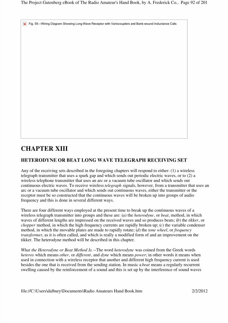
8/3/2019 Radio Amateurs Hand Book
http://slidepdf.com/reader/full/radio-amateurs-hand-book 92/201
CHAPTER XIII
HETERODYNE OR BEAT LONG WAVE TELEGRAPH RECEIVING SET
Any of the receiving sets described in the foregoing chapters will respond to either: (1) a wirelesstelegraph transmitter that uses a spark gap and which sends out periodic electric waves, or to (2) awireless telephone transmitter that uses an arc or a vacuum tube oscillator and which sends outcontinuous electric waves. To receive wireless telegraph signals, however, from a transmitter that uses anarc or a vacuum tube oscillator and which sends out continuous waves, either the transmitter or thereceptor must be so constructed that the continuous waves will be broken up into groups of audiofrequency and this is done in several different ways.
There are four different ways employed at the present time to break up the continuous waves of awireless telegraph transmitter into groups and these are: (a) the heterodyne, or beat , method, in whichwaves of different lengths are impressed on the received waves and so produces beats; (b) the tikker , or
chopper method, in which the high frequency currents are rapidly broken up; (c) the variable condensermethod, in which the movable plates are made to rapidly rotate; (d ) the tone wheel, or frequencytransformer , as it is often called, and which is really a modified form of and an improvement on thetikker. The heterodyne method will be described in this chapter.
What the Heterodyne or Beat Method Is.--The word heterodyne was coined from the Greek wordsheteros which means other , or different , and dyne which means power ; in other words it means whenused in connection with a wireless receptor that another and different high frequency current is usedbesides the one that is received from the sending station. In music a beat means a regularly recurrentswelling caused by the reinforcement of a sound and this is set up by the interference of sound waves
Fig.59.--WiringDiagramShowingLongWaveReceptorwithVariocouplersandBank-woundInductanceCoils
Page 92 of 201The Project Gutenberg eBook of The Radio Amateur's Hand Book, by A. Frederick Co...
2/2/2012file://C:\Users\dalbury\Documents\Radio Amateurs Hand Book.htm
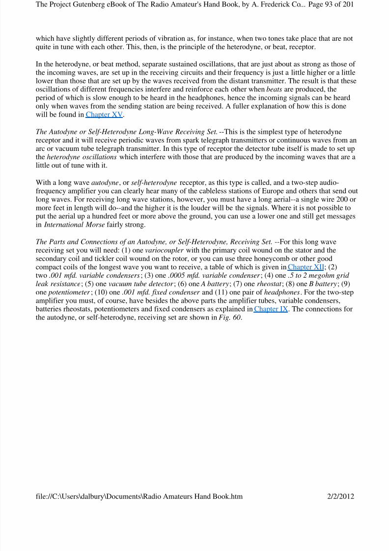
8/3/2019 Radio Amateurs Hand Book
http://slidepdf.com/reader/full/radio-amateurs-hand-book 93/201
which have slightly different periods of vibration as, for instance, when two tones take place that are notquite in tune with each other. This, then, is the principle of the heterodyne, or beat, receptor.
In the heterodyne, or beat method, separate sustained oscillations, that are just about as strong as those of the incoming waves, are set up in the receiving circuits and their frequency is just a little higher or a littlelower than those that are set up by the waves received from the distant transmitter. The result is that theseoscillations of different frequencies interfere and reinforce each other when beats are produced, the
period of which is slow enough to be heard in the headphones, hence the incoming signals can be heardonly when waves from the sending station are being received. A fuller explanation of how this is donewill be found in Chapter XV.
The Autodyne or Self-Heterodyne Long-Wave Receiving Set.--This is the simplest type of heterodynereceptor and it will receive periodic waves from spark telegraph transmitters or continuous waves from anarc or vacuum tube telegraph transmitter. In this type of receptor the detector tube itself is made to set upthe heterodyne oscillations which interfere with those that are produced by the incoming waves that are alittle out of tune with it.
With a long wave autodyne, or self-heterodyne receptor, as this type is called, and a two-step audio-
frequency amplifier you can clearly hear many of the cableless stations of Europe and others that send outlong waves. For receiving long wave stations, however, you must have a long aerial--a single wire 200 ormore feet in length will do--and the higher it is the louder will be the signals. Where it is not possible toput the aerial up a hundred feet or more above the ground, you can use a lower one and still get messagesin International Morse fairly strong.
The Parts and Connections of an Autodyne, or Self-Heterodyne, Receiving Set.--For this long wavereceiving set you will need: (1) one variocoupler with the primary coil wound on the stator and thesecondary coil and tickler coil wound on the rotor, or you can use three honeycomb or other goodcompact coils of the longest wave you want to receive, a table of which is given in Chapter XII; (2)two .001 mfd. variable condensers; (3) one .0005 mfd. variable condenser ; (4) one .5 to 2 megohm grid leak resistance; (5) one vacuum tube detector ; (6) one A battery; (7) one rheostat ; (8) one B battery; (9)
one potentiometer ; (10) one .001 mfd. fixed condenser and (11) one pair of headphones. For the two-stepamplifier you must, of course, have besides the above parts the amplifier tubes, variable condensers,batteries rheostats, potentiometers and fixed condensers as explained in Chapter IX. The connections forthe autodyne, or self-heterodyne, receiving set are shown in Fig. 60.
Page 93 of 201The Project Gutenberg eBook of The Radio Amateur's Hand Book, by A. Frederick Co...
2/2/2012file://C:\Users\dalbury\Documents\Radio Amateurs Hand Book.htm
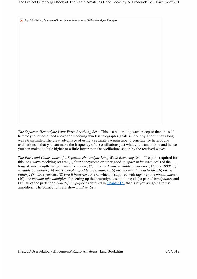
8/3/2019 Radio Amateurs Hand Book
http://slidepdf.com/reader/full/radio-amateurs-hand-book 94/201
The Separate Heterodyne Long Wave Receiving Set.--This is a better long wave receptor than the self heterodyne set described above for receiving wireless telegraph signals sent out by a continuous longwave transmitter. The great advantage of using a separate vacuum tube to generate the heterodyneoscillations is that you can make the frequency of the oscillations just what you want it to be and henceyou can make it a little higher or a little lower than the oscillations set up by the received waves.
The Parts and Connections of a Separate Heterodyne Long Wave Receiving Set.--The parts required forthis long wave receiving set are: (1) four honeycomb or other good compact inductance coils of thelongest wave length that you want to receive; (2) three .001 mfd. variable condensers; (3) one .0005 mfd.variable condenser ; (4) one 1 megohm grid leak resistance; (5) one vacuum tube detector ; (6) one Abattery; (7) two rheostats; (8) two B batteries, one of which is supplied with taps; (9) one potentiometer ;(10) one vacuum tube amplifier , for setting up the heterodyne oscillations; (11) a pair of headphones and(12) all of the parts for a two-step amplifier as detailed in Chapter IX, that is if you are going to useamplifiers. The connections are shown in Fig. 61.
Fig.60.--WiringDiagramofLongWaveAntodyne,orSelf-HeterodyneReceptor.
Page 94 of 201The Project Gutenberg eBook of The Radio Amateur's Hand Book, by A. Frederick Co...
2/2/2012file://C:\Users\dalbury\Documents\Radio Amateurs Hand Book.htm
8/3/2019 Radio Amateurs Hand Book
http://slidepdf.com/reader/full/radio-amateurs-hand-book 95/201
In using either of these heterodyne receivers be sure to carefully adjust the B battery by means of thepotentiometer.
[Footnote: The amplifier tube in this case is used as a generator of oscillations.]
CHAPTER XIV
HEADPHONES AND LOUD SPEAKERS
Wireless Headphones.--A telephone receiver for a wireless receiving set is made exactly on the sameprinciple as an ordinary Bell telephone receiver. The only difference between them is that the former ismade flat and compact so that a pair of them can be fastened together with a band and worn on the head(when it is called a headset ), while the latter is long and cylindrical so that it can be held to the ear. Afurther difference between them is that the wireless headphone is made as sensitive as possible so that itwill respond to very feeble currents, while the ordinary telephone receiver is far from being sensitive andwill respond only to comparatively large currents.
Fig.61.--WiringDiagramofLongWaveSeparateHeterodyneReceivingSet.
Page 95 of 201The Project Gutenberg eBook of The Radio Amateur's Hand Book, by A. Frederick Co...
2/2/2012file://C:\Users\dalbury\Documents\Radio Amateurs Hand Book.htm

8/3/2019 Radio Amateurs Hand Book
http://slidepdf.com/reader/full/radio-amateurs-hand-book 96/201
How a Bell Telephone Receiver Is Made.--An ordinary telephone receiver consists of three chief parts andthese are: (1) a hard-rubber, or composition, shell and cap, (2) a permanent steel bar magnet on one endof which is wound a coil of fine insulated copper wire, and (3) a soft iron disk, or diaphragm, all of which are shown in the cross-section in Fig. 62. The bar magnet is securely fixed inside of the handle sothat the outside end comes to within about 1/32 of an inch of the diaphragm when this is laid on top of theshell and the cap is screwed on.
The ends of the coil of wire are connected with two binding posts which are in the end of the shell, butare shown in the picture at the sides for the sake of clearness. This coil usually has a resistance of about75 ohms and the meaning of the ohmic resistance of a receiver and its bearing on the sensitiveness of itwill be explained a little farther along. After the disk, or diaphragm, which is generally made of thin, soft
sheet iron that has been tinned or japanned, [Footnote: A disk of photographic tin-type plate is generallyused.] is placed over the end of the magnet, the cap, which has a small opening in it, is screwed on andthe receiver is ready to use.
How a Wireless Headphone Is Made.--For wireless work a receiver of the watch-case type is used andnearly always two such receivers are connected with a headband. It consists of a permanent bar magnetbent so that it will fit into the shell of the receiver as shown at A in Fig. 63.
Fig.62.--Cross-sectionofBelltelephoneReceiver.
Photograph unavailable
original © Underwood and Underwood.Alexander Graham Bell, Inventor of the Telephone, now an ardent Radio Enthusiast.
Page 96 of 201The Project Gutenberg eBook of The Radio Amateur's Hand Book, by A. Frederick Co...
2/2/2012file://C:\Users\dalbury\Documents\Radio Amateurs Hand Book.htm
8/3/2019 Radio Amateurs Hand Book
http://slidepdf.com/reader/full/radio-amateurs-hand-book 97/201
The ends of this magnet, which are called poles, are bent up, and hence this type is called a bipolar receiver. The magnets are wound with fine insulated wire as before and the diaphragm is held securely inplace over them by screwing on the cap.
About Resistance, Turns of Wire and Sensitivity of Headphones.--If you are a beginner in wireless youwill hear those who are experienced speak of a telephone receiver as having a resistance of 75 ohms,
1,000 ohms, 2,000 or 3,000 ohms, as the case may be; from this you will gather that the higher theresistance of the wire on the magnets the more sensitive the receiver is. In a sense this is true, but it is notthe resistance of the magnet coils that makes it sensitive, in fact, it cuts down the current, but it is thenumber of turns of wire on them that determines its sensitiveness; it is easy to see that this is so, for thelarger the number of turns the more often will the same current flow round the cores of the magnet and somagnetize them to a greater extent.
But to wind a large number of turns of wire close enough to the cores to be effective the wire must bevery small and so, of course, the higher the resistance will be. Now the wire used for winding goodreceivers is usually No. 40, and this has a diameter of .0031 inch; consequently, when you know theohmic resistance you get an idea of the number of turns of wire and from this you gather in a general waywhat the sensitivity of the receiver is.
A receiver that is sensitive enough for wireless work should be wound to not less than 1,000 ohms (thismeans each ear phone), while those of a better grade are wound to as high as 3,000 ohms for each one. Ahigh-grade headset is shown in Fig. 64. Each phone of a headset should be wound to the same resistance,and these are connected in series as shown. Where two or more headsets are used with one wirelessreceiving set they must all be of the same resistance and connected in series, that is, the coils of one headset are connected with the coils of the next head set and so on to form a continuous circuit.
Fig.63.--WirelessHeadphone.
Page 97 of 201The Project Gutenberg eBook of The Radio Amateur's Hand Book, by A. Frederick Co...
2/2/2012file://C:\Users\dalbury\Documents\Radio Amateurs Hand Book.htm

8/3/2019 Radio Amateurs Hand Book
http://slidepdf.com/reader/full/radio-amateurs-hand-book 98/201
The Impedance of Headphones.--When a current is flowing through a circuit the material of which thewire is made not only opposes its passage--this is called its ohmic resistance--but a counter-electromotiveorce to the current is set up due to the inductive effects of the current on itself and this is called
impedance. Where a wire is wound in a coil the impedance of the circuit is increased and where analternating current is used the impedance grows greater as the frequency gets higher. The impedance of the magnet coils of a receiver is so great for high frequency oscillations that the latter cannot pass throughthem; in other words, they are choked off.
How the Headphones Work.--As you will see from the cross-sections in Figs. 62 and 63 there is noconnection, electrical or mechanical, between the diaphragm and the other parts of the receiver. Nowwhen either feeble oscillations, which have been rectified by a detector, or small currents from a B battery, flow through the magnet coils the permanent steel magnet is energized to a greater extent thanwhen no current is flowing through it. This added magnetic energy makes the magnet attract thediaphragm more than it would do by its own force. If, on the other hand, the current is cut off the pull of the magnet is lessened and as its attraction for the diaphragm is decreased the latter springs back to itsoriginal position. When varying currents flow through the coils the diaphragm vibrates accordingly andsends out sound waves.
About Loud Speakers.--The simplest acoustic instrument ever invented is the megaphone, which latter isa Greek word meaning great sound . It is a very primitive device and our Indians made it out of birch-bark
before Columbus discovered America. In its simplest form it consists of a cone-shaped horn and as thespeaker talks into the small end the concentrated sound waves pass out of the large end in whateverdirection it is held.
Now a loud speaker of whatever kind consists of two chief parts and these are: (1) a telephone receiver ,and (2) a megaphone, or horn as it is called. A loud speaker when connected with a wireless receiving setmakes it possible for a room, or an auditorium, full of people, or an outdoor crowd, to hear what is beingsent out by a distant station instead of being limited to a few persons listening-in with headphones. To usea loud speaker you should have a vacuum tube detector receiving set and this must be provided with aone-step amplifier at least.
Fig.64.--WirelessHeadphone.
Page 98 of 201The Project Gutenberg eBook of The Radio Amateur's Hand Book, by A. Frederick Co...
2/2/2012file://C:\Users\dalbury\Documents\Radio Amateurs Hand Book.htm

8/3/2019 Radio Amateurs Hand Book
http://slidepdf.com/reader/full/radio-amateurs-hand-book 99/201

8/3/2019 Radio Amateurs Hand Book
http://slidepdf.com/reader/full/radio-amateurs-hand-book 100/201
A Third Kind of Simple Loud Speaker.--The operation of the Amplitron, [Footnote: Made by the RadioService Co., 110 W. 40th Street, N. Y.] as this loud speaker is called, is slightly different from othersused for the same purpose. The sounds set up by the headphone are conveyed to the apex of an invertedcopper cone which is 7 inches long and 10 inches in diameter. Here it is reflected by a parabolic mirrorwhich greatly amplifies the sounds. The amplification takes place without distortion, the soundsremaining as clear and crisp as when projected by the transmitting station. By removing the cap from thereceiver the shell is screwed into a receptacle on the end of the loud speaker and the instrument is readyfor use. It is pictured in Fig. 67 .
Fig.66.--AmplitoneLoudSpeaker.
Fig.67.--AmplitronLoudSpeaker.
Page 100 of 201The Project Gutenberg eBook of The Radio Amateur's Hand Book, by A. Frederick ...
2/2/2012file://C:\Users\dalbury\Documents\Radio Amateurs Hand Book.htm
8/3/2019 Radio Amateurs Hand Book
http://slidepdf.com/reader/full/radio-amateurs-hand-book 101/201
A Super Loud Speaker.--This loud speaker, which is known as the Magnavox Telemegafone, was theinstrument used by Lt. Herbert E. Metcalf, 3,000 feet in the air, and which startled the City of Washington on April 2, 1919, by repeating President Wilson's Victory Loan Message from an airplane inflight so that it was distinctly heard by 20,000 people below.
This wonderful achievement was accomplished through the installation of the Magnavox and amplifiersin front of the Treasury Building. Every word Lt. Metcalf spoke into his wireless telephone transmitter
was caught and swelled in volume by the Telemegafones below and persons blocks away could hear themessage plainly. Two kinds of these loud speakers are made and these are: (1) a small loud speaker forthe use of operators so that headphones need not be worn, and (2) a large loud speaker for auditorium andout-door audiences.
Either kind may be used with a one- or two-step amplifier or with a cascade of half a dozen amplifiers,according to the degree of loudness desired. The Telemegafone itself is not an amplifier in the true senseinasmuch as it contains no elements which will locally increase the incoming current. It does, however,transform the variable electric currents of the wireless receiving set into sound vibrations in a mostwonderful manner.
A telemegafone of either kind is formed of: (1) a telephone receiver of large proportions, (2) a step-downinduction coil, and (3) a 6 volt storage battery that energizes a powerful electromagnet which works the
diaphragm. An electromagnet is used instead of a permanent magnet and this is energized by a 6-voltstorage battery as shown in the wiring diagram at A in Fig. 68. One end of the core of this magnet is fixedto the iron case of the speaker and together these form the equivalent of a horseshoe magnet. A movablecoil of wire is supported from the center of the diaphragm the edge of which is rigidly held between thecase and the small end of the horn. This coil is placed over the upper end of the magnet and its terminalsare connected to the secondary of the induction coil. Now when the coil is energized by the current fromthe amplifiers it and the core act like a solenoid in that the coil tends to suck the core into it; but since thecore is fixed and the coil is movable the core draws the coil down instead. The result is that with everyvariation of the current that flows through the coil it moves up and down and pulls and pushes thediaphragm down and up with it. The large amplitude of the vibrations of the latter set up powerful soundwaves which can be heard several blocks away from the horn. In this way then are the faint incomingsignals, speech and music which are received by the amplifying receiving set reproduced and magnifiedenormously. The Telemegafone is shown complete at B.
Photograph unavailable
original © Underwood and Underwood.World's Largest Loud Speaker ever made. Installed in Lytle Park, Cincinnati, Ohio, to permit
President Harding's Address at Point Pleasant, Ohio, during the Grant Centenary Celebration to be
heard within a radius of one square.
Page 101 of 201The Project Gutenberg eBook of The Radio Amateur's Hand Book, by A. Frederick ...
2/2/2012file://C:\Users\dalbury\Documents\Radio Amateurs Hand Book.htm
8/3/2019 Radio Amateurs Hand Book
http://slidepdf.com/reader/full/radio-amateurs-hand-book 102/201
CHAPTER XV
OPERATION OF VACUUM TUBE RECEPTORS
From the foregoing chapters you have seen that the vacuum tube can be used either as a detector or anamplifier or as a generator of electric oscillations, as in the case of the heterodyne receiving set. Tounderstand how a vacuum tube acts as a detector and as an amplifier you must first know what electrons are. The way in which the vacuum tube sets up sustained oscillations will be explained in Chapter XVIII in connection with the Operation of Vacuum Tube Transmitters.
What Electrons Are.--Science teaches us that masses of matter are made up of molecules, that each of these is made up of atoms, and each of these, in turn, is made up of a central core of positive particles of electricity surrounded by negative particles of electricity as shown in the schematic diagram, Fig. 69. Thelittle black circles inside the large circle represent positive particles of electricity and the little whitecircles outside of the large circle represent negative particles of electricity, or electrons as they are called.
Fig.68.--MagnavoxLoudSpeaker.
Page 102 of 201The Project Gutenberg eBook of The Radio Amateur's Hand Book, by A. Frederick ...
2/2/2012file://C:\Users\dalbury\Documents\Radio Amateurs Hand Book.htm
8/3/2019 Radio Amateurs Hand Book
http://slidepdf.com/reader/full/radio-amateurs-hand-book 103/201
It is the number of positive particles of electricity an atom has that determines the kind of an element thatis formed when enough atoms of the same kind are joined together to build it up. Thus hydrogen, whichis the lightest known element, has one positive particle for its nucleus, while uranium, the heaviestelement now known, has 92 positive particles. Now before leaving the atom please note that it is as muchsmaller than the diagram as the latter is smaller than our solar system.
What Is Meant by Ionization.--A hydrogen atom is not only lighter but it is smaller than the atom of anyother element while an electron is more than a thousand times smaller than the atom of which it is a part.Now as long as all of the electrons remain attached to the surface of an atom its positive and negativecharges are equalized and it will, therefore, be neither positive nor negative, that is, it will be perfectlyneutral. When, however, one or more of its electrons are separated from it, and there are several ways bywhich this can be done, the atom will show a positive charge and it is then called a positive ion.
In other words a positive ion is an atom that has lost some of its negative electrons while a negative ion isone that has acquired some additional negative electrons. When a number of electrons are beingconstantly given by the atoms of an element, which let us suppose is a metal, and are being attracted toatoms of another element, which we will say is also a metal, a flow of electrons takes place between the
two oppositely charged elements and form a current of negative electricity as represented by the arrows at A in Fig. 70.
Fig.69.--SchematicDiagramofanAtom.
Page 103 of 201The Project Gutenberg eBook of The Radio Amateur's Hand Book, by A. Frederick ...
2/2/2012file://C:\Users\dalbury\Documents\Radio Amateurs Hand Book.htm

8/3/2019 Radio Amateurs Hand Book
http://slidepdf.com/reader/full/radio-amateurs-hand-book 104/201
When a stream of electrons is flowing between two metal elements, as a filament and a plate in a vacuumtube detector, or an amplifier, they act as carriers for more negative electrons and these are supplied by abattery as we shall presently explain. It has always been customary for us to think of a current of electricity as flowing from the positive pole of a battery to the negative pole of it and hence we havecalled this the direction of the current . Since the electronic theory has been evolved it has been shownthat the electrons, or negative charges of electricity, flow from the negative to the positive pole and thatthe ionized atoms, which are more positive than negative, flow in the opposite direction as shown at B.
How Electrons are Separated from Atoms.--The next question that arises is how to make a metal throwoff some of the electrons of the atoms of which it is formed. There are several ways that this can be donebut in any event each atom must be given a good, hard blow. A simple way to do this is to heat a metal toincandescence when the atoms will bombard each other with terrific force and many of the electrons willbe knocked off and thrown out into the surrounding space.
But all, or nearly all, of them will return to the atoms from whence they came unless a means of somekind is employed to attract them to the atoms of some other element. This can be done by giving the latterpiece of metal a positive charge. If now these two pieces of metal are placed in a bulb from which the airhas been exhausted and the first piece of metal is heated to brilliancy while the second piece of metal iskept positively electrified then a stream of electrons will flow between them.
Action of the Two Electrode Vacuum Tube.--Now in a vacuum tube detector a wire filament, like that of an incandescent lamp, is connected with a battery and this forms the hot element from which theelectrons are thrown off, and a metal plate with a terminal wire secured to it is connected to the positiveor carbon tap of a dry battery; now connect the negative or zinc tap of this with one end of a telephone
receiver and the other end of this with the terminals of the filament as shown at A in Fig. 71. If now youheat the filament and hold the phone to your ear you can hear the current from the B battery flowingthrough the circuit.
Fig.70.--ActionofTwo-electrodeVacuumTube.
Page 104 of 201The Project Gutenberg eBook of The Radio Amateur's Hand Book, by A. Frederick ...
2/2/2012file://C:\Users\dalbury\Documents\Radio Amateurs Hand Book.htm
8/3/2019 Radio Amateurs Hand Book
http://slidepdf.com/reader/full/radio-amateurs-hand-book 105/201
Since the electrons are negative charges of electricity they are not only thrown off by the hot wire butthey are attracted by the positive charged metal plate and when enough electrons pass, or flow, from thehot wire to the plate they form a conducting path and so complete the circuit which includes the filament,the plate and the B or plate battery, when the current can then flow through it. As the number of electronsthat are thrown off by the filament is not great and the voltage of the plate is not high the current thatflows between the filament and the plate is always quite small.
How the Two Electrode Tube Acts as a Detector.--As the action of a two electrode tube as a detector[Footnote: The three electrode vacuum tube has entirely taken the place of the two electrode type.] issimpler than that of the three electrode vacuum tube we shall describe it first. The two electrode vacuum
(A)and(B)Fig.71.--HowaTwoElectrodeTubeActsasaRelayoraDetector.
(C)Fig.71.--OnlythePositivePartofOscillationsGoesthroughtheTube.
Page 105 of 201The Project Gutenberg eBook of The Radio Amateur's Hand Book, by A. Frederick ...
2/2/2012file://C:\Users\dalbury\Documents\Radio Amateurs Hand Book.htm
8/3/2019 Radio Amateurs Hand Book
http://slidepdf.com/reader/full/radio-amateurs-hand-book 106/201
tube was first made by Mr. Edison when he was working on the incandescent lamp but that it would serveas a detector of electric waves was discovered by Prof. Fleming, of Oxford University, London. As amatter of fact, it is not really a detector of electric waves, but it acts as: (1) a rectifier of the oscillationsthat are set up in the receiving circuits, that is, it changes them into pulsating direct currents so that theywill flow through and affect a telephone receiver, and (2) it acts as a relay and the feeble receivedoscillating current controls the larger direct current from the B battery in very much the same way that atelegraph relay does. This latter relay action will be explained when we come to its operation as an
amplifier.
We have just learned that when the stream of electrons flow from the hot wire to the cold positive plate inthe tube they form a conducting path through which the battery current can flow. Now when the electricoscillations surge through the closed oscillation circuit, which includes the secondary of the tuning coil,the variable condenser, the filament and the plate as shown at B in Fig. 71 the positive part of thempasses through the tube easily while the negative part cannot get through, that is, the top, or positive, partof the wave-form remains intact while the lower, or negative, part is cut off as shown in the diagram at C .As the received oscillations are either broken up into wave trains of audio frequency by the telegraphtransmitter or are modulated by a telephone transmitter they carry the larger impulses of the direct currentfrom the B battery along with them and these flow through the headphones. This is the reason the vacuum
tube amplifies as well as detects.
How the Three Electrode Tube Acts as a Detector.--The vacuum tube as a detector has been made verymuch more sensitive by the use of a third electrode shown in Fig. 72. In this type of vacuum tube thethird electrode, or grid , is placed between the filament and the plate and this controls the number of electrons flowing from the filament to the plate; in passing between these two electrodes they have to gothrough the holes formed by the grid wires.
(A)and(B)Fig.72.--HowthePositiveandNegativeVoltagesofOscillationsActontheElectrons.
Page 106 of 201The Project Gutenberg eBook of The Radio Amateur's Hand Book, by A. Frederick ...
2/2/2012file://C:\Users\dalbury\Documents\Radio Amateurs Hand Book.htm
8/3/2019 Radio Amateurs Hand Book
http://slidepdf.com/reader/full/radio-amateurs-hand-book 107/201
If now the grid is charged to a higher negative voltage than the filament the electrons will be stopped bythe latter, see A, though some of them will go through to the plate because they travel at a high rate of speed. The higher the negative charge on the grid the smaller will be the number of electrons that willreach the plate and, of course, the smaller will be the amount of current that will flow through the tubeand the headphones from the B battery.
(C)Fig.72.--HowtheThreeElectrodeTubeActsasaDetectorandAmplifier.
(D)Fig.72.--HowtheOscillationsControltheFlowoftheBatteryCurrentthroughtheTube.
Page 107 of 201The Project Gutenberg eBook of The Radio Amateur's Hand Book, by A. Frederick ...
2/2/2012file://C:\Users\dalbury\Documents\Radio Amateurs Hand Book.htm

8/3/2019 Radio Amateurs Hand Book
http://slidepdf.com/reader/full/radio-amateurs-hand-book 108/201
On the other hand if the grid is charged positively, see B, then more electrons will strike the plate thanwhen the grid is not used or when it is negatively charged. But when the three electrode tube is used as adetector the oscillations set up in the circuits change the grid alternately from negative to positive asshown at C and hence the voltage of the B battery current that is allowed to flow through the detectorfrom the plate to the filament rises and falls in unison with the voltage of the oscillating currents. Theway the positive and negative voltages of the oscillations which are set up by the incoming waves,energize the grid; how the oscillator tube clips off the negative parts of them, and, finally, how these
carry the battery current through the tube are shown graphically by the curves at D.
How the Vacuum Tube Acts as an Amplifier .--If you connect up the filament and the plate of a threeelectrode tube with the batteries and do not connect in the grid, you will find that the electrons which arethrown off by the filament will not get farther than the grid regardless of how high the voltage is that youapply to the plate. This is due to the fact that a large number of electrons which are thrown off by thefilament strike the grid and give it a negative charge, and consequently, they cannot get any farther. Sincethe electrons do not reach the plate the current from the B battery cannot flow between it and the filament.
Now with a properly designed amplifier tube a very small negative voltage on the grid will keep a verylarge positive voltage on the plate from sending a current through the tube, and oppositely, a very small
positive voltage on the grid will let a very large plate current flow through the tube; this being true itfollows that any small variation of the voltage from positive to negative on the grid and the other wayabout will vary a large current flowing from the plate to the filament.
In the Morse telegraph the relay permits the small current that is received from the distant sending stationto energize a pair of magnets, and these draw an armature toward them and close a second circuit when alarge current from a local battery is available for working the sounder. The amplifier tube is a variablerelay in that the feeble currents set up by the incoming waves constantly and proportionately vary a largecurrent that flows through the headphones. This then is the principle on which the amplifying tube works.
The Operation of a Simple Vacuum Tube Receiving Set .--The way a simple vacuum tube detectorreceiving set works is like this: when the filament is heated to brilliancy it gives off electrons as
previously described. Now when the electric waves impinge on the aerial wire they set up oscillations init and these surge through the primary coil of the loose coupled tuning coil, a diagram of which is shownat B in Fig. 41.
The energy of these oscillations sets up oscillations of the same frequency in the secondary coil and thesehigh frequency currents whose voltage is first positive and then negative, surge in the closed circuitwhich includes the secondary coil and the variable condenser. At the same time the alternating positiveand negative voltage of the oscillating currents is impressed on the grid; at each change from + to - andback again it allows the electrons to strike the plate and then shuts them off; as the electrons form theconducting path between the filament and the plate the larger direct current from the B battery ispermitted to flow through the detector tube and the headphones.
Operation of a Regenerative Vacuum Tube Receiving Set .--By feeding back the pulsating direct currentfrom the B battery through the tickler coil it sets up other and stronger oscillations in the secondary of thetuning coil when these act on the detector tube and increase its sensitiveness to a remarkable extent. Theregenerative, or feed back , action of the receiving circuits used will be easily understood by referringback to B in Fig. 47 .
When the waves set up oscillations in the primary of the tuning coil the energy of them produces likeoscillations in the closed circuit which includes the secondary coil and the condenser; the alternatingpositive and negative voltages of these are impressed on the grid and these, as we have seen before, cause
Page 108 of 201The Project Gutenberg eBook of The Radio Amateur's Hand Book, by A. Frederick ...
2/2/2012file://C:\Users\dalbury\Documents\Radio Amateurs Hand Book.htm
8/3/2019 Radio Amateurs Hand Book
http://slidepdf.com/reader/full/radio-amateurs-hand-book 109/201
similar variations of the direct current from the B battery which acts on the plate and which flowsbetween the latter and the filament.
This varying direct current, however, is made to flow back through the third, or tickler coil of the tuningcoil and sets up in the secondary coil and circuits other and larger oscillating currents and these augmentthe action of the oscillations produced by the incoming waves. These extra and larger currents which arethe result of the feedback then act on the grid and cause still larger variations of the current in the plate
voltage and hence of the current of the B battery that flows through the detector and the headphones. Atthe same time the tube keeps on responding to the feeble electric oscillations set up in the circuits by theincoming waves. This regenerative action of the battery current augments the original oscillations manytimes and hence produce sounds in the headphones that are many times greater than where the vacuumtube detector alone is used.
Operation of Autodyne and Heterodyne Receiving Sets.--On page 109 [Chapter VII] we discussed and at A in Fig. 36 is shown a picture of two tuning forks mounted on sounding boxes to illustrate the principleof electrical tuning. When a pair of these forks are made to vibrate exactly the same number of times persecond there will be a condensation of the air between them and the sound waves that are sent out will beaugmented. But if you adjust one of the forks so that it will vibrate 256 times a second and the other fork
so that it will vibrate 260 times a second then there will be a phase difference between the two sets of waves and the latter will augment each other 4 times every second and you will hear these rising andfalling sounds as beats.
Now electric oscillations set up in two circuits that are coupled together act in exactly the same way assound waves produced by two tuning forks that are close to each other. Since this is true if you tune oneof the closed circuits so that the oscillations in it will have a frequency of a 1,000,000 and tune the othercircuit so that the oscillations in it have a frequency of 1,001,000 a second then the oscillations willaugment each other 1,000 times every second.
As these rising and falling currents act on the pulsating currents from the B battery which flow throughthe detector tube and the headphones you will hear them as beats. A graphic representation of the
oscillating currents set up by the incoming waves, those produced by the heterodyne oscillator and thebeats they form is shown in Fig. 73. To produce these beats a receptor can use: (1) a single vacuum tubefor setting up oscillations of both frequencies when it is called an autodyne, or self-heterodyne receptor,or (2) a separate vacuum tube for setting up the oscillations for the second circuit when it is called aheterodyne receptor.
Page 109 of 201The Project Gutenberg eBook of The Radio Amateur's Hand Book, by A. Frederick ...
2/2/2012file://C:\Users\dalbury\Documents\Radio Amateurs Hand Book.htm
8/3/2019 Radio Amateurs Hand Book
http://slidepdf.com/reader/full/radio-amateurs-hand-book 110/201
The Autodyne, or Self-Heterodyne Receiving Set .--Where only one vacuum tube is used for producingboth frequencies you need only a regenerative, or feed-back receptor; then you can tune the aerial wire
system to the incoming waves and tune the closed circuit of the secondary coil so that it will be out of step with the former by 1,000 oscillations per second, more or less, the exact number does not matter inthe least. From this you will see that any regenerative set can be used for autodyne, or self-heterodyne,reception.
The Separate Heterodyne Receiving Set.--The better way, however, is to use a separate vacuum tube forsetting up the heterodyne oscillations. The latter then act on the oscillations that are produced by theincoming waves and which energize the grid of the detector tube. Note that the vacuum tube used forproducing the heterodyne oscillations is a generator of electric oscillations; the latter are impressed onthe detector circuits through the variable coupling, the secondary of which is in series with the aerial wire
Fig.73.--HowtheHeterodyneReceptorWorks.
Page 110 of 201The Project Gutenberg eBook of The Radio Amateur's Hand Book, by A. Frederick ...
2/2/2012file://C:\Users\dalbury\Documents\Radio Amateurs Hand Book.htm
8/3/2019 Radio Amateurs Hand Book
http://slidepdf.com/reader/full/radio-amateurs-hand-book 111/201
as shown in Fig. 74. The way in which the tube acts as a generator of oscillations will be told in ChapterXVIII.
CHAPTER XVI
CONTINUOUS WAVE TELEGRAPH TRANSMITTING SETS WITH DIRECTCURRENT
In the first part of this book we learned about spark-gap telegraph sets and how the oscillations they setup are damped and the waves they send out are periodic. In this and the next chapter we shall find outhow vacuum tube telegraph transmitters are made and how they set up oscillations that are sustained andradiate waves that are continuous.
Sending wireless telegraph messages by continuous waves has many features to recommend it as againstsending them by periodic waves and among the most important of these are that the transmitter can be:(1) more sharply tuned, (2) it will send signals farther with the same amount of power, and (3) it isnoiseless in operation. The disadvantageous features are that: (1) a battery current is not satisfactory, (2)its circuits are somewhat more complicated, and (3) the oscillator tubes burn out occasionally. There is,however, a growing tendency among amateurs to use continuous wave transmitters and they are certainlymore up-to-date and interesting than spark gap sets.
Now there are two practical ways by which continuous waves can be set up for sending either telegraphicsignals or telephonic speech and music and these are with: (a) an oscillation arc lamp, and (b) a vacuumtube oscillator . The oscillation arc was the earliest known way of setting up sustained oscillations, and itis now largely used for commercial high power, long distance work. But since the vacuum tube has beendeveloped to a high degree of efficiency and is the scheme that is now in vogue for amateur stations weshall confine our efforts here to explaining the apparatus necessary and how to wire the various parts
Fig.74.--SeparateHeterodyneOscillator.
Page 111 of 201The Project Gutenberg eBook of The Radio Amateur's Hand Book, by A. Frederick ...
2/2/2012file://C:\Users\dalbury\Documents\Radio Amateurs Hand Book.htm
8/3/2019 Radio Amateurs Hand Book
http://slidepdf.com/reader/full/radio-amateurs-hand-book 112/201
together to produce several sizes of vacuum tube telegraph transmitters.
Sources of Current for Telegraph Transmitting Sets.--Differing from a spark-gap transmitter you cannotget any appreciable results with a low voltage battery current to start with. For a purely experimentalvacuum tube telegraph transmitter you can use enough B batteries to operate it but the current strength of these drops so fact when they are in use, that they are not at all satisfactory for the work.
You can, however, use 110 volt direct current from a lighting circuit as your initial source of power toenergize the plate of the vacuum tube oscillator of your experimental transmitter. Where you have a 110volt direct current lighting service in your home and you want a higher voltage for your plate, you willthen have to use a motor-generator set and this costs money. If you have 110 volt alternating current lighting service at hand your troubles are over so far as cost is concerned for you can step it up to anyvoltage you want with a power transformer. In this chapter will be shown how to use a direct current foryour source of initial power and in the next chapter how to use an alternating current for the initial power.
An Experimental Continuous Wave Telegraph Transmitter.--You will remember that in Chapter XV welearned how the heterodyne receiver works and that in the separate heterodyne receiving set the secondvacuum tube is used solely to set up oscillations. Now while this extra tube is used as a generator of
oscillations these are, of course, very weak and hence a detector tube cannot be used to generateoscillations that are useful for other purposes than heterodyne receptors and measurements.
There is a vacuum tube amplifier [Footnote: This is the radiation UV-201, made by the RadioCorporation of America, Woolworth Bldg., New York City.] made that will stand a plate potential of 100volts, and this can be used as a generator of oscillations by energizing it with a 110 volt direct currentfrom your lighting service. Or in a pinch you can use five standard B batteries to develop the platevoltage, but these will soon run down. But whatever you do, never use a current from a lighting circuit ona tube of any kind that has a rated plate potential of less than 100 volts.
The Apparatus You Need .--For this experimental continuous wave telegraph transmitter get the followingpieces of apparatus: (1) one single coil tuner with three clips; (2) one .002 mfd. fixed condenser ; (3)three .001 mfd. condensers; (4) one adjustable grid leak ; (5) one hot-wire ammeter ; (6) one buzzer ; (7)one dry cell; (8) one telegraph key; (9) one 100 volt plate vacuum tube amplifier ; (10) one 6 volt storagebattery; (11) one rheostat ; (12) one oscillation choke coil; (13) one panel cut-out with a single-throw,double-pole switch, and a pair of fuse sockets on it.
The Tuning Coil.--You can either make this tuning coil or buy one. To make it get two disks of wood 3/4-inch thick and 5 inches in diameter and four strips of hard wood, or better, hard rubber or compositionstrips, such as bakelite, 1/2-inch thick, 1 inch wide and 5-3/4 inches long, and screw them to the disks asshown at A in Fig. 75. Now wrap on this form about 25 turns of No. 8 or 10, Brown and Sharpe gauge,bare copper wire with a space of 1/8-inch between each turn. Get three of the smallest size terminal clips,see B, and clip them on to the different turns, when your tuning coil is ready for use. You can buy a coil
of this kind for $4.00 or $5.00.
The Condensers.--For the aerial series condenser get one that has a capacitance of .002 mfd. and that willstand a potential of 3,000 volts. [Footnote: The U C-1014 Faradon condenser made by the RadioCorporation of America will serve the purpose.] It is shown at C . The other three condensers, see D, arealso of the fixed type and may have a capacitance of .001 mfd.; [Footnote: List No. 266; fixed receivingcondenser, sold by the Manhattan Electrical Supply Co.] the blocking condenser should preferably have acapacitance of 1/2 a mfd. In these condensers the leaves of the sheet metal are embedded in composition.The aerial condenser will cost you $2.00 and the others 75 cents each.
Page 112 of 201The Project Gutenberg eBook of The Radio Amateur's Hand Book, by A. Frederick ...
2/2/2012file://C:\Users\dalbury\Documents\Radio Amateurs Hand Book.htm

8/3/2019 Radio Amateurs Hand Book
http://slidepdf.com/reader/full/radio-amateurs-hand-book 113/201

8/3/2019 Radio Amateurs Hand Book
http://slidepdf.com/reader/full/radio-amateurs-hand-book 114/201
The Aerial Ammeter.--This instrument is also called a hot-wire ammeter because the oscillating currentsflowing through a piece of wire heat it according to their current strength and as the wire contracts andexpands it moves a needle over a scale. The ammeter is connected in the aerial wire system, either in theaerial side or the ground side--the latter place is usually the most convenient. When you tune thetransmitter so that the ammeter shows the largest amount of current surging in the aerial wire system youcan consider that the oscillation circuits are in tune. A hot-wire ammeter reading to 2.5 amperes willserve your needs, it costs $6.00 and is shown at E in Fig. 75.
The Buzzer and Dry Cell.--While a heterodyne, or beat, receptor can receive continuous wave telegraphsignals an ordinary crystal or vacuum tube detector receiving set cannot receive them unless they arebroken up into trains either at the sending station or at the receiving station, and it is considered the betterpractice to do this at the former rather than at the latter station. For this small transmitter you can use an
Fig.75.--ApparatusforExperimentalC.W.TelegraphTransmitter.
Photograph unavailable
United States Naval High Power Station, Arlington Va. General view of Power Room. At the leftcan be seen the Control Switchboards, and overhead, the great 30 K.W. Arc Transmitter with
Accessories.
Page 114 of 201The Project Gutenberg eBook of The Radio Amateur's Hand Book, by A. Frederick ...
2/2/2012file://C:\Users\dalbury\Documents\Radio Amateurs Hand Book.htm

8/3/2019 Radio Amateurs Hand Book
http://slidepdf.com/reader/full/radio-amateurs-hand-book 115/201
ordinary buzzer as shown at F . A dry cell or two must be used to energize the buzzer. You can get one forabout 75 cents.
The Telegraph Key.--Any kind of a telegraph key will serve to break up the trains of sustainedoscillations into dots and dashes. The key shown at G is mounted on a composition base and is thecheapest key made, costing $1.50.
The Vacuum Tube Oscillator .--As explained before you can use any amplifying tube that is made for aplate potential of 100 volts. The current required for heating the filament is about 1 ampere at 6 volts. Aporcelain socket should be used for this tube as it is the best insulating material for the purpose. Anamplifier tube of this type is shown at H and costs $6.50.
The Storage Battery.--A storage battery is used to heat the filament of the tube, just as it is with a detectortube, and it can be of any make or capacity as long as it will develop 6 volts. The cheapest 6 volt storagebattery on the market has a 20 to 40 ampere-hour capacity and sells for $13.00.
The Battery Rheostat .--As with the receptors a rheostat is needed to regulate the current that heats thefilament. A rheostat of this kind is shown at I and is listed at $1.25.
The Oscillation Choke Coil.--This coil is connected in between the oscillation circuits and the source of current which feeds the oscillator tube to keep the oscillations set up by the latter from surging back intothe service wires where they would break down the insulation. You can make an oscillation choke coil bywinding say 100 turns of No. 28 Brown and Sharpe gauge double cotton covered magnet wire on acardboard cylinder 2 inches in diameter and 2-1/2 inches long.
Transmitter Connectors.--For connecting up the different pieces of apparatus of the transmitter it is agood scheme to use copper braid ; this is made of braided copper wire in three sizes and sells for 7,15 and20 cents a foot respectively. A piece of it is pictured at J .
The Panel Cut-Out .--This is used to connect the cord of the 110-volt lamp socket with the transmitter. Itconsists of a pair of plug cutouts and a single-throw, double-pole switch mounted on a porcelain base asshown at K . In some localities it is necessary to place these in an iron box to conform to the requirementsof the fire underwriters.
Connecting Up the Transmitting Apparatus.--The way the various pieces of apparatus are connectedtogether is shown in the wiring diagram. Fig. 76 . Begin by connecting one post of the ammeter with thewire that leads to the aerial and the other post of it to one end of the tuning coil; connect clip 1 to oneterminal of the .002 mfd. 3,000 volt aerial condenser and the other post of this with the ground.
Page 115 of 201The Project Gutenberg eBook of The Radio Amateur's Hand Book, by A. Frederick ...
2/2/2012file://C:\Users\dalbury\Documents\Radio Amateurs Hand Book.htm
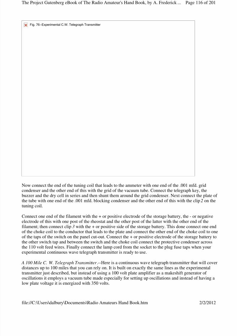
8/3/2019 Radio Amateurs Hand Book
http://slidepdf.com/reader/full/radio-amateurs-hand-book 116/201
Now connect the end of the tuning coil that leads to the ammeter with one end of the .001 mfd. gridcondenser and the other end of this with the grid of the vacuum tube. Connect the telegraph key, thebuzzer and the dry cell in series and then shunt them around the grid condenser. Next connect the plate of the tube with one end of the .001 mfd. blocking condenser and the other end of this with the clip 2 on thetuning coil.
Connect one end of the filament with the + or positive electrode of the storage battery, the - or negativeelectrode of this with one post of the rheostat and the other post of the latter with the other end of thefilament; then connect clip 3 with the + or positive side of the storage battery. This done connect one endof the choke coil to the conductor that leads to the plate and connect the other end of the choke coil to one
of the taps of the switch on the panel cut-out. Connect the + or positive electrode of the storage battery tothe other switch tap and between the switch and the choke coil connect the protective condenser acrossthe 110 volt feed wires. Finally connect the lamp cord from the socket to the plug fuse taps when yourexperimental continuous wave telegraph transmitter is ready to use.
A 100 Mile C. W. Telegraph Transmitter .--Here is a continuous wave telegraph transmitter that will coverdistances up to 100 miles that you can rely on. It is built on exactly the same lines as the experimentaltransmitter just described, but instead of using a 100 volt plate amplifier as a makeshift generator of oscillations it employs a vacuum tube made especially for setting up oscillations and instead of having alow plate voltage it is energized with 350 volts.
Fig.76--ExperimentalC.W.TelegraphTransmitter
Page 116 of 201The Project Gutenberg eBook of The Radio Amateur's Hand Book, by A. Frederick ...
2/2/2012file://C:\Users\dalbury\Documents\Radio Amateurs Hand Book.htm
8/3/2019 Radio Amateurs Hand Book
http://slidepdf.com/reader/full/radio-amateurs-hand-book 117/201
The Apparatus You Need .--For this transmitter you require: (1) one oscillation transformer ; (2) one hot-wire ammeter ; (3) one aerial series condenser ; (4) one grid leak resistance; (5) one chopper ; (6) one keycircuit choke coil; (7) one 5 watt vacuum tube oscillator ; (8) one 6 volt storage battery; (9) one batteryrheostat ; (10) one battery voltmeter ; (11) one blocking condenser ; (12) one power circuit choke coil, and(13) one motor-generator .
The Oscillation Transformer .--The tuning coil, or oscillation transformer as this one is called, is a
conductively coupled tuner--that is, the primary and secondary coils form one continuous coil instead of two separate coils. This tuner is made up of 25 turns of thin copper strip, 3/8 inch wide and with its edgesrounded, and this is secured to a wood base as shown at A in Fig. 77 . It is fitted with one fixed tap andthree clips to each of which a length of copper braid is attached. It has a diameter of 6-1/4 inches, a heightof 7-7/8 inches and a length of 9-3/8 inches, and it costs $11.00.
Page 117 of 201The Project Gutenberg eBook of The Radio Amateur's Hand Book, by A. Frederick ...
2/2/2012file://C:\Users\dalbury\Documents\Radio Amateurs Hand Book.htm
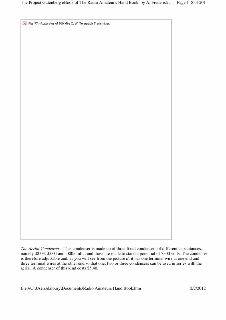
8/3/2019 Radio Amateurs Hand Book
http://slidepdf.com/reader/full/radio-amateurs-hand-book 118/201
8/3/2019 Radio Amateurs Hand Book
http://slidepdf.com/reader/full/radio-amateurs-hand-book 119/201
The Aerial Ammeter .--This is the same kind of a hot-wire ammeter already described in connection withthe experimental set, but it reads to 5 amperes.
The Grid and Blocking Condensers.--Each of these is a fixed condenser of .002 mfd. capacitance and israted to stand 3,000 volts. It is made like the aerial condenser but has only two terminals. It costs $2.00.
The Key Circuit Apparatus.--This consists of: (1) the grid leak ; (2) the chopper ; (3) the choke coil, and
(4) the key. The grid leak is connected in the lead from the grid to the aerial to keep the voltage on thegrid at the right potential. It has a resistance of 5000 ohms with a mid-tap at 2500 ohms as shown at C . Itcosts $2.00.
The chopper is simply a rotary interrupter driven by a small motor. It comprises a wheel of insulatingmaterial in which 30 or more metal segments are set in an insulating disk as shown at D. A metal contactcalled a brush is fixed on either side of the wheel. It costs about $7.00 and the motor to drive it is extra.The choke coil is wound up of about 250 turns of No. 30 Brown and Sharpe gauge cotton covered magnetwire on a spool which has a diameter of 2 inches and a length of 3-1/4 inches.
The 5 Watt Oscillator Vacuum Tube.--This tube is made like the amplifier tube described for use with the
preceding experimental transmitter, but it is larger, has a more perfect vacuum, and will stand a platepotential of 350 volts while the plate current is .045 ampere. The filament takes a current of a little morethan 2 amperes at 7.5 volts. A standard 4-tap base is used with it. The tube costs $8.00 and the porcelainbase is $1.00 extra. It is shown at E .
The Storage Battery and Rheostat .--This must be a 5-cell battery so that it will develop 10 volts. Astorage battery of any capacity can be used but the lowest priced one costs about $22.00. The rheostat forregulating the battery current is the same as that used in the preceding experimental transmitter.
The Filament Voltmeter .--To get the best results it is necessary that the voltage of the current which heatsthe filament be kept at the same value all of the time. For this transmitter a direct current voltmeterreading from 0 to 15 volts is used. It is shown at F and costs $7.50.
The Oscillation Choke Coil.--This is made exactly like the one described in connection with theexperimental transmitter.
The Motor-Generator Set .--Where you have only a 110 or a 220 volt direct current available as a sourceof power you need a motor-generator to change it to 350 volts, and this is an expensive piece of apparatus. It consists of a single armature core with a motor winding and a generator winding on it andeach of these has its own commutator. Where the low voltage current flows into one of the windings itdrives its as a motor and this in turn generates the higher voltage current in the other winding. Get a 100watt 350 volt motor-generator; it is shown at F and costs about $75.00.
The Panel Cut-Out .--This switch and fuse block is the same as that used in the experimental set.
The Protective Condenser .--This is a fixed condenser having a capacitance of 1 mfd. and will stand 750volts. It costs $2.00.
Connecting Up the Transmitting Apparatus.--From all that has gone before you have seen that each pieceof apparatus is fitted with terminal, wires, taps or binding posts. To connect up the parts of thistransmitter it is only necessary to make the connections as shown in the wiring diagram Fig. 78.
Page 119 of 201The Project Gutenberg eBook of The Radio Amateur's Hand Book, by A. Frederick ...
2/2/2012file://C:\Users\dalbury\Documents\Radio Amateurs Hand Book.htm
8/3/2019 Radio Amateurs Hand Book
http://slidepdf.com/reader/full/radio-amateurs-hand-book 120/201
A 200 Mile C. W. Telegraph Transmitter .--To make a continuous wave telegraph transmitter that willcover distances up to 200 miles all you have to do is to use two 5 watt vacuum tubes in parallel, all of therest of the apparatus being exactly the same. Connecting the oscillator tubes up in parallel means that the
two filaments are connected across the leads of the storage battery, the two grids on the same lead thatgoes to the aerial and the two plates on the same lead that goes to the positive pole of the generator.Where two or more oscillator tubes are used only one storage battery is needed, but each filament musthave its own rheostat. The wiring diagram Fig. 79 shows how the two tubes are connected up in parallel.
Fig.78.--5to50WattC.W.TelegraphTransmitter.(WithSingleOscillationTube.)
Page 120 of 201The Project Gutenberg eBook of The Radio Amateur's Hand Book, by A. Frederick ...
2/2/2012file://C:\Users\dalbury\Documents\Radio Amateurs Hand Book.htm

8/3/2019 Radio Amateurs Hand Book
http://slidepdf.com/reader/full/radio-amateurs-hand-book 121/201
A 500 Mile C. W. Telegraph Transmitter .--For sending to distances of over 200 miles and up to 500 milesyou can use either: (1) three or four 5 watt oscillator tubes in parallel as described above, or (2) one 50watt oscillator tube. Much of the apparatus for a 50 watt tube set is exactly the same as that used for the 5watt sets. Some of the parts, however, must be proportionately larger though the design all the waythrough remains the same.
The Apparatus and Connections.--The aerial series condenser, the blocking condenser, the gridcondenser, the telegraph key, the chopper, the choke coil in the key circuit, the filament voltmeter and the
protective condenser in the power circuit are identical with those described for the 5 watt transmitting set.
The 50 Watt Vacuum Tube Oscillator .--This is the size of tube generally used by amateurs for longdistance continuous wave telegraphy. A single tube will develop 2 to 3 amperes in your aerial. Thefilament takes a 10 volt current and a plate potential of 1,000 volts is needed. One of these tubes is shownin Fig. 80 and the cost is $30.00. A tube socket to fit it costs $2.50 extra.
Fig.79.--200MileC.W.TelegraphTransmitter(WithTwoTubesinParallel.)
Fig.80.--50WattOscillatorVacuumTube.
Page 121 of 201The Project Gutenberg eBook of The Radio Amateur's Hand Book, by A. Frederick ...
2/2/2012file://C:\Users\dalbury\Documents\Radio Amateurs Hand Book.htm

8/3/2019 Radio Amateurs Hand Book
http://slidepdf.com/reader/full/radio-amateurs-hand-book 122/201
The Aerial Ammeter .--This should read to 5 amperes and the cost is $6.25.
The Grid Leak Resistance.--It has the same resistance, namely 5,000 ohms as the one used with the 5 watttube transmitter, but it is a little larger. It is listed at $1.65.
The Oscillation Choke Coil.--The choke coil in the power circuit is made of about 260 turns of No. 30 B.& S. cotton covered magnet wire wound on a spool 2-1/4 inches in diameter and 3-1/4 inches long.
The Filament Rheostat .--This is made to take care of a 10 volt current and it costs $10.00.
The Filament Storage Battery.--This must develop 12 volts and one having an output of 40 ampere-hourscosts about $25.00.
The Protective Condenser .--This condenser has a capacitance of 1 mfd. and costs $2.00.
The Motor-Generator .--Where you use one 50 watt oscillator tube you will need a motor-generator thatdevelops a plate potential of 1000 volts and has an output of 200 watts. This machine will stand youabout $100.00.
The different pieces of apparatus for this set are connected up exactly the same as shown in the wiringdiagram in Fig. 78.
A 1000 Mile C. W. Telegraph Transmitter .--All of the parts of this transmitting set are the same as for the500 mile transmitter just described except the motor generator and while this develops the same platepotential, i.e., 1,000 volts, it must have an output of 500 watts; it will cost you in the neighborhood of $175.00. For this long distance transmitter you use two 50 watt oscillator tubes in parallel and all of theparts are connected together exactly the same as for the 200 mile transmitter shown in the wiring diagramin Fig. 79.
CHAPTER XVIICONTINUOUS WAVE TELEGRAPH TRANSMITTING SETS WITHALTERNATING CURRENT
Within the last few years alternating current has largely taken the place of direct current for light, heatand power purposes in and around towns and cities and if you have alternating current service in yourhome you can install a long distance continuous wave telegraph transmitter with very little trouble and ata comparatively small expense.
A 100 Mile C. W. Telegraph Transmitting Set .--The principal pieces of apparatus for this transmitter are
the same as those used for the 100 Mile Continuous Wave Telegraph Transmitting Set described andpictured in the preceding chapter which used direct current, except that an alternating current power transformer is employed instead of the more costly motor-generator .
The Apparatus Required .--The various pieces of apparatus you will need for this transmitting set are: (1)one hot-wire ammeter for the aerial as shown at E in Fig. 75, but which reads to 5 amperes instead of to2.5 amperes; (2) one tuning coil as shown at A in Fig. 77 ; (3) one aerial condenser as shown at B in Fig.77 ; (4) one grid leak as shown at C in Fig. 77 ; (5) one telegraph key as shown at G in Fig. 75; (6) onegrid condenser , made like the aerial condenser but having only two terminals; (7) one 5 watt oscillator tube as shown at E in Fig. 77 ; (8) one .002 mfd. 3,000 volt by-pass condenser , made like the aerial and
Page 122 of 201The Project Gutenberg eBook of The Radio Amateur's Hand Book, by A. Frederick ...
2/2/2012file://C:\Users\dalbury\Documents\Radio Amateurs Hand Book.htm
8/3/2019 Radio Amateurs Hand Book
http://slidepdf.com/reader/full/radio-amateurs-hand-book 123/201
grid condensers; (9) one pair of choke coils for the high voltage secondary circuit; (10) one milli-ammeter ; (11) one A. C. power transformer ; (12) one rheostat as shown at I in Fig. 75, and (13) one
anel cut-out as shown at K in Fig. 75.
The Choke Coils.--Each of these is made by winding about 100 turns of No. 28, Brown and Sharpegauge, cotton covered magnet wire on a spool 2 inches in diameter and 2-1/2 inches long, when it willhave an inductance of about 0.5 millihenry [Footnote: A millihenry is 1/1000th part of a henry.] at 1,000
cycles.
The Milli-ammeter .--This is an alternating current ammeter and reads from 0 to 250 milliamperes;[Footnote: A milliampere is the 1/1000th part of an ampere.] and is used for measuring the secondarycurrent that energizes the plate of the oscillator tube. It looks like the aerial ammeter and costs about$7.50.
The A. C. Power Transformer .--Differing from the motor generator set the power transformer has nomoving parts. For this transmitting set you need a transformer that has an input of 325 volts. It is made towork on a 50 to 60 cycle current at 102.5 to 115 volts, which is the range of voltage of the ordinaryalternating lighting current. This adjustment for voltage is made by means of taps brought out from the
primary coil to a rotary switch.
The high voltage secondary coil which energizes the plate has an output of 175 watts and develops apotential of from 350 to 1,100 volts. The low voltage secondary coil which heats the filament has anoutput of 175 watts and develops 7.5 volts. This transformer, which is shown in Fig. 81, is large enoughto take care of from one to four 5 watt oscillator tubes. It weighs about 15 pounds and sells for $25.00.
Page 123 of 201The Project Gutenberg eBook of The Radio Amateur's Hand Book, by A. Frederick ...
2/2/2012file://C:\Users\dalbury\Documents\Radio Amateurs Hand Book.htm
8/3/2019 Radio Amateurs Hand Book
http://slidepdf.com/reader/full/radio-amateurs-hand-book 124/201
Connecting Up the Apparatus.--The wiring diagram Fig. 82 shows clearly how all of the connections aremade. It will be observed that a storage battery is not needed as the secondary coil of the transformersupplies the current to heat the filament of the oscillator. The filament voltmeter is connected across thefilament secondary coil terminals, while the plate milli-ammeter is connected to the mid-taps of the platesecondary coil and the filament secondary coil.
Fig.81.--AlternationCurrentPowerTransformer.(ForC.W.TelegraphyandWirelessTelephony.)
Photograph unavailable
The Transformer and Tuner of the World's Largest Radio Station. Owned by the RadioCorporation of America at Rocky Point near Port Jefferson L.I.
Page 124 of 201The Project Gutenberg eBook of The Radio Amateur's Hand Book, by A. Frederick ...
2/2/2012file://C:\Users\dalbury\Documents\Radio Amateurs Hand Book.htm

8/3/2019 Radio Amateurs Hand Book
http://slidepdf.com/reader/full/radio-amateurs-hand-book 125/201
A 200 to 500 Mile C. W. Telegraph Transmitting Set .--Distances of from 200 to 500 miles can besuccessfully covered with a telegraph transmitter using two, three or four 5 watt oscillator tubes inparallel. The apparatus needed is identical with that used for the 100 mile transmitter just described. Thetubes are connected in parallel as shown in the wiring diagram in Fig. 83.
A 500 to 1,000 Mile C. W. Telegraph Transmitting Set .--With the apparatus described for the above setand a single 50 watt oscillator tube a distance of upwards of 500 miles can be covered, while with two 50watt oscillator tubes in parallel you can cover a distance of 1,000 miles without difficulty, and nearly2,000 miles have been covered with this set.
The Apparatus Required .--All of the apparatus for this C. W. telegraph transmitting set is the same as thatdescribed for the 100 and 200 mile sets but you will need: (1) one or two 50 watt oscillator tubes withsockets; (2) one key condenser that has a capacitance of 1 mfd., and a rated potential of 1,750 volts; (3)
Fig.82.WiringDiagramfor200to500MileC.W.TelegraphTransmittingSet.(WithAlternatingCurrent)
Fig.83.--WiringDiagramfor500to1000MileC.W.TelegraphTransmitter.
Page 125 of 201The Project Gutenberg eBook of The Radio Amateur's Hand Book, by A. Frederick ...
2/2/2012file://C:\Users\dalbury\Documents\Radio Amateurs Hand Book.htm
8/3/2019 Radio Amateurs Hand Book
http://slidepdf.com/reader/full/radio-amateurs-hand-book 126/201
8/3/2019 Radio Amateurs Hand Book
http://slidepdf.com/reader/full/radio-amateurs-hand-book 127/201
The distance that can be covered with a wireless telephone transmitter is about one-fourth as great as thatof a wireless telegraph transmitter having the same input of initial current, but it is long enough to satisfythe most enthusiastic amateur. For instance with a wireless telephone transmitter where an amplifier tubeis used to set up the oscillations and which is made for a plate potential of 100 volts, distances up to 10 or15 miles can be covered.
With a single 5 watt oscillator tube energized by a direct current of 350 volts from either a motor-
generator or from a power transformer (after it has been rectified and smoothed out) speech and musiccan be transmitted to upwards of 25 miles. Where two 5 watt tubes connected in parallel are used wirelesstelephone messages can be transmitted to distances of 40 or 50 miles. Further, a single 50 watt oscillatortube will send to distances of 50 to 100 miles while two of these tubes in parallel will send from 100 to200 miles. Finally, where four or five oscillator tubes are connected in parallel proportionately greaterdistances can be covered.
A Short Distance Wireless Telephone Transmitting Set-With 110 Volt Direct Lighting Current .--For thisvery simple, short distance wireless telephone transmitting set you need the same apparatus as thatdescribed and pictured in the beginning of Chapter XVI for a Short Distance C. W. TelegraphTransmitter , except that you use a microphone transmitter instead of a telegraph key. If you have a 110
volt direct lighting current in your home you can put up this short distance set for very little money and itwill be well worth your while to do so.
The Apparatus You Need .--For this set you require: (1) one tuning coil as shown at A and B in Fig. 75; (2)one aerial ammeter as shown at C in Fig. 75; (3) one aerial condenser as shown at C in Fig. 75; (4) onegrid, blocking and protective condenser as shown at D in Fig. 75; (5) one grid leak as shown at C in Fig.77 ; (6) one vacuum tube amplifier which is used as an oscillator ; (7) one 6 volt storage battery; (8) onerheostat as shown at I in Fig. 75; (9) one oscillation choke coil; (10) one panel cut-out as shown at K inFig. 75 and an ordinary microphone transmitter .
The Microphone Transmitter .--The best kind of a microphone to use with this and other telephonetransmitting sets is a Western Electric No. 284-W . [Footnote: Made by the Western Electric Company,
Chicago, Ill.] This is known as a solid back transmitter and is the standard commercial type used on alllong distance Bell telephone lines. It articulates sharply and distinctly and there are no current variationsto distort the wave form of the voice and it will not buzz or sizzle. It is shown in Fig. 84 and costs $2.00.Any other good microphone transmitter can be used if desired.
Page 127 of 201The Project Gutenberg eBook of The Radio Amateur's Hand Book, by A. Frederick ...
2/2/2012file://C:\Users\dalbury\Documents\Radio Amateurs Hand Book.htm
8/3/2019 Radio Amateurs Hand Book
http://slidepdf.com/reader/full/radio-amateurs-hand-book 128/201

8/3/2019 Radio Amateurs Hand Book
http://slidepdf.com/reader/full/radio-amateurs-hand-book 129/201
Next connect one end of the grid condenser to the post of the tuning coil that makes connection with themicrophone and the other end to the grid of the tube, and then shunt the grid leak around the condenser.Connect the + or positive electrode of the storage battery with one terminal of the filament of the vacuumtube, the other terminal of the filament with one post of the rheostat and the other post of this with the - ornegative electrode of the battery. This done, connect clip 2 of the tuning coil to the + or positive electrodeof the battery and bring a lead from it to one of the switch taps of the panel cut-out.
Now connect clip 3 of the tuning coil with one end of the blocking condenser, the other end of this withone terminal of the choke coil and the other terminal of the latter with the other switch tap of the cut-out.Connect the protective condenser across the direct current feed wires between the panel cut-out and the
choke coil. Finally connect the ends of a lamp cord to the fuse socket taps of the cut-out, and connect theother ends to a lamp plug and screw it into the lamp socket of the feed wires. Screw in a pair of 5 ampereuse plugs, close the switch and you are ready to tune the transmitter and talk to your friends.
A 25 to 50 Mile Wireless Telephone Transmitter--With Direct Current Motor Generator .--Where youhave to start with 110 or 220 volt direct current and you want to transmit to a distance of 25 miles ormore you will have to install a motor-generator . To make this transmitter you will need exactly the sameapparatus as that described and pictured for the 100 Mile C. W. Telegraph Transmitting Set in ChapterXVI, except that you must substitute a microphone transmitter and a telephone induction coil, or amicrophone transformer , or still better, a magnetic modulator , for the telegraph key and chopper.
Fig.85.--WiringDiagramofShortDistanceWirelessTelephoneSet.(MicrophoneinAerialWire.)
Page 129 of 201The Project Gutenberg eBook of The Radio Amateur's Hand Book, by A. Frederick ...
2/2/2012file://C:\Users\dalbury\Documents\Radio Amateurs Hand Book.htm

8/3/2019 Radio Amateurs Hand Book
http://slidepdf.com/reader/full/radio-amateurs-hand-book 130/201
The Apparatus You Need .--To reiterate; the pieces of apparatus you need are: (1) one aerial ammeter asshown at E in Fig. 75; (2) one tuning coil as shown at A in Fig. 77 ; (3) one aerial condenser as shown at B in Fig. 77 ; (4) one grid leak as shown at C in Fig. 77 ; (5) one grid, blocking and protective condenser ;(6) one 5 watt oscillator tube as shown at E in Fig. 77 ; (7) one rheostat as shown at I in Fig. 75; (8) one10 volt (5 cell) storage battery; (9) one choke coil; (10) one panel cut-out as shown at K in Fig. 75, and(11) a motor-generator having an input of 110 or 220 volts and an output of 350 volts.
In addition to the above apparatus you will need: (12) a microphone transmitter as shown in Fig. 84; (13)a battery of four dry cells or a 6 volt storage battery, and either (14) a telephone induction coil as shownin Fig. 86 ; (15) a microphone transformer as shown in Fig. 87 ; or a magnetic modulator as shown in Fig.88. All of these parts have been described, as said above, in Chapter XVI, except the microphonemodulators.
Fig.86.--TelephoneInductionCoil.(UsedwithMicrophoneTransmitter.)
Page 130 of 201The Project Gutenberg eBook of The Radio Amateur's Hand Book, by A. Frederick ...
2/2/2012file://C:\Users\dalbury\Documents\Radio Amateurs Hand Book.htm
8/3/2019 Radio Amateurs Hand Book
http://slidepdf.com/reader/full/radio-amateurs-hand-book 131/201
Fig.87.--MicrophoneTransformer.(UsedwithMicrophoneTransmitter.)
Page 131 of 201The Project Gutenberg eBook of The Radio Amateur's Hand Book, by A. Frederick ...
2/2/2012file://C:\Users\dalbury\Documents\Radio Amateurs Hand Book.htm
8/3/2019 Radio Amateurs Hand Book
http://slidepdf.com/reader/full/radio-amateurs-hand-book 132/201
The Telephone Induction Coil.--This is a little induction coil that transforms the 6-volt battery current
after it has flowed through and been modulated by the microphone transmitter into alternating currentsthat have a potential of 1,000 volts of more. It consists of a primary coil of No. 20 B. and S. gauge cottoncovered magnet wire wound on a core of soft iron wires while around the primary coil is wound asecondary coil of No. 30 magnet wire. Get a standard telephone induction coil that has a resistance of 500 or 750 ohms and this will cost you a couple of dollars.
The Microphone Transformer .--This device is built on exactly the same principle as the telephoneinduction coil just described but it is more effective because it is designed especially for modulating theoscillations set up by vacuum tube transmitters. As with the telephone induction coil, the microphonetransmitter is connected in series with the primary coil and a 6 volt dry or storage battery.
Fig.88.--MagneticModulator.(UsedwithMicrophoneTransmitter.)
Page 132 of 201The Project Gutenberg eBook of The Radio Amateur's Hand Book, by A. Frederick ...
2/2/2012file://C:\Users\dalbury\Documents\Radio Amateurs Hand Book.htm

8/3/2019 Radio Amateurs Hand Book
http://slidepdf.com/reader/full/radio-amateurs-hand-book 133/201
In the better makes of microphone transformer, there is a third winding, called a side tone coil, to which aheadphone can be connected so that the operator who is speaking into the microphone can listen-in and solearn if his transmitter is working up to standard.
The Magnetic Modulator .--This is a small closed iron core transformer of peculiar design and having aprimary and a secondary coil wound on it. This device is used to control the variations of the oscillatingcurrents that are set up by the oscillator tube. It is made in three sizes and for the transmitter here
described you want the smallest size, which has an output of 1/2 to 1-1/2 amperes. It costs about $10.00.
How the Apparatus Is Connected Up.--The different pieces of apparatus are connected together in exactlythe same way as the 100 Mile C. W. Telegraph Set in Chapter XVI except that the microphone transmitterand microphone modulator (whichever kind you use) is substituted for the telegraph key and chopper.
Now there are three different ways that the microphone and its modulator can be connected in circuit.Two of the best ways are shown at A and B in Fig. 89. In the first way the secondary terminals of themodulator are shunted around the grid leak in the grid circuit as at A, and in the second the secondaryterminals are connected in the aerial as at B. Where an induction coil or a microphone transformer is usedthey are shunted around a condenser, but this is not necessary with the magnetic modulator. Where a
second tube is used as in Fig. 90 then the microphone and its modulator are connected with the gridcircuit and clip 3 of the tuning coil.
Fig.89.--WiringDiagramof25to50MileWirelessTelephone.(MicrophoneModulatorShuntedAroundGrid-LeakCondenser.)
Page 133 of 201The Project Gutenberg eBook of The Radio Amateur's Hand Book, by A. Frederick ...
2/2/2012file://C:\Users\dalbury\Documents\Radio Amateurs Hand Book.htm

8/3/2019 Radio Amateurs Hand Book
http://slidepdf.com/reader/full/radio-amateurs-hand-book 134/201
(B)Fig.89.--MicrophoneModulatorConnectedinAerialWire.
Page 134 of 201The Project Gutenberg eBook of The Radio Amateur's Hand Book, by A. Frederick ...
2/2/2012file://C:\Users\dalbury\Documents\Radio Amateurs Hand Book.htm
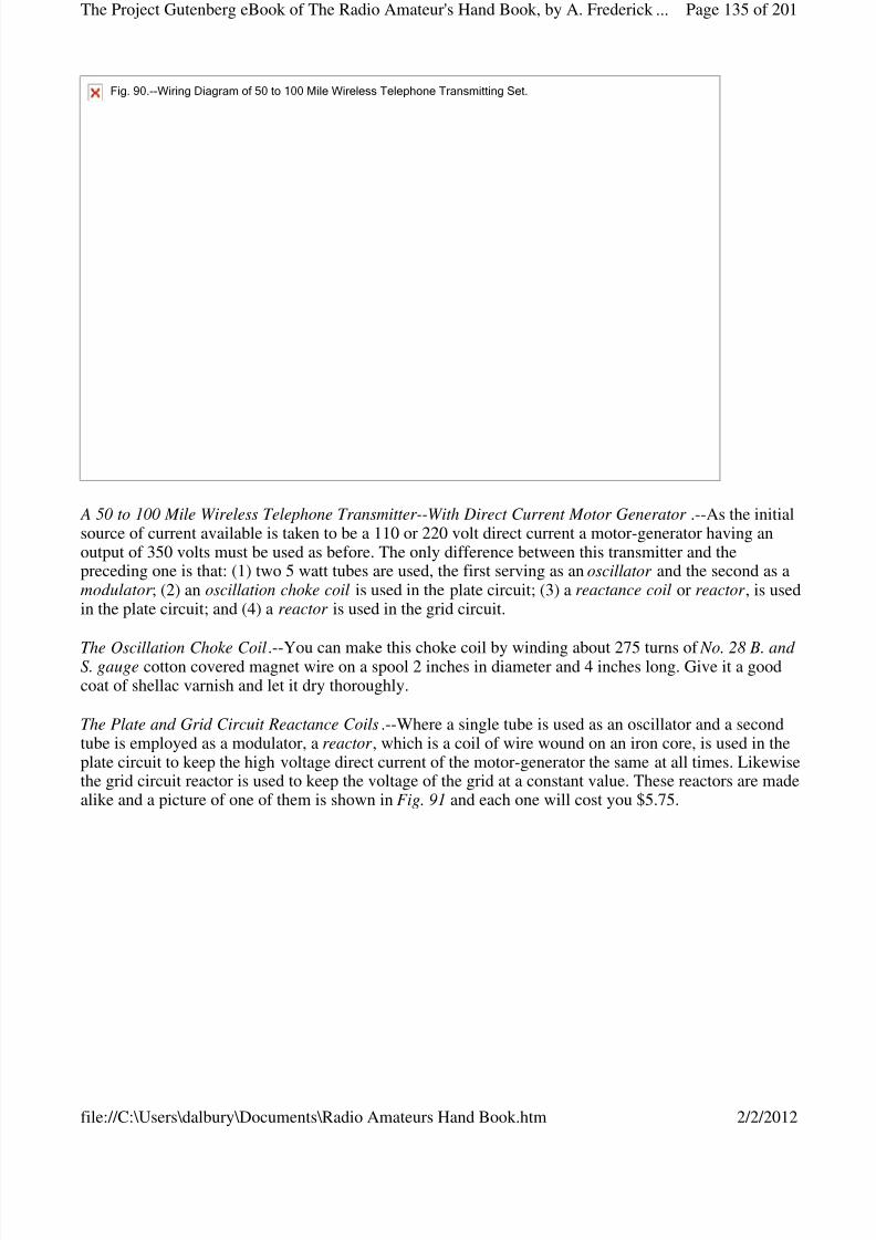
8/3/2019 Radio Amateurs Hand Book
http://slidepdf.com/reader/full/radio-amateurs-hand-book 135/201
A 50 to 100 Mile Wireless Telephone Transmitter--With Direct Current Motor Generator .--As the initialsource of current available is taken to be a 110 or 220 volt direct current a motor-generator having anoutput of 350 volts must be used as before. The only difference between this transmitter and thepreceding one is that: (1) two 5 watt tubes are used, the first serving as an oscillator and the second as amodulator ; (2) an oscillation choke coil is used in the plate circuit; (3) a reactance coil or reactor , is usedin the plate circuit; and (4) a reactor is used in the grid circuit.
The Oscillation Choke Coil.--You can make this choke coil by winding about 275 turns of No. 28 B. and S. gauge cotton covered magnet wire on a spool 2 inches in diameter and 4 inches long. Give it a goodcoat of shellac varnish and let it dry thoroughly.
The Plate and Grid Circuit Reactance Coils.--Where a single tube is used as an oscillator and a secondtube is employed as a modulator, a reactor , which is a coil of wire wound on an iron core, is used in theplate circuit to keep the high voltage direct current of the motor-generator the same at all times. Likewisethe grid circuit reactor is used to keep the voltage of the grid at a constant value. These reactors are madealike and a picture of one of them is shown in Fig. 91 and each one will cost you $5.75.
Fig.90.--WiringDiagramof50to100MileWirelessTelephoneTransmittingSet.
Page 135 of 201The Project Gutenberg eBook of The Radio Amateur's Hand Book, by A. Frederick ...
2/2/2012file://C:\Users\dalbury\Documents\Radio Amateurs Hand Book.htm
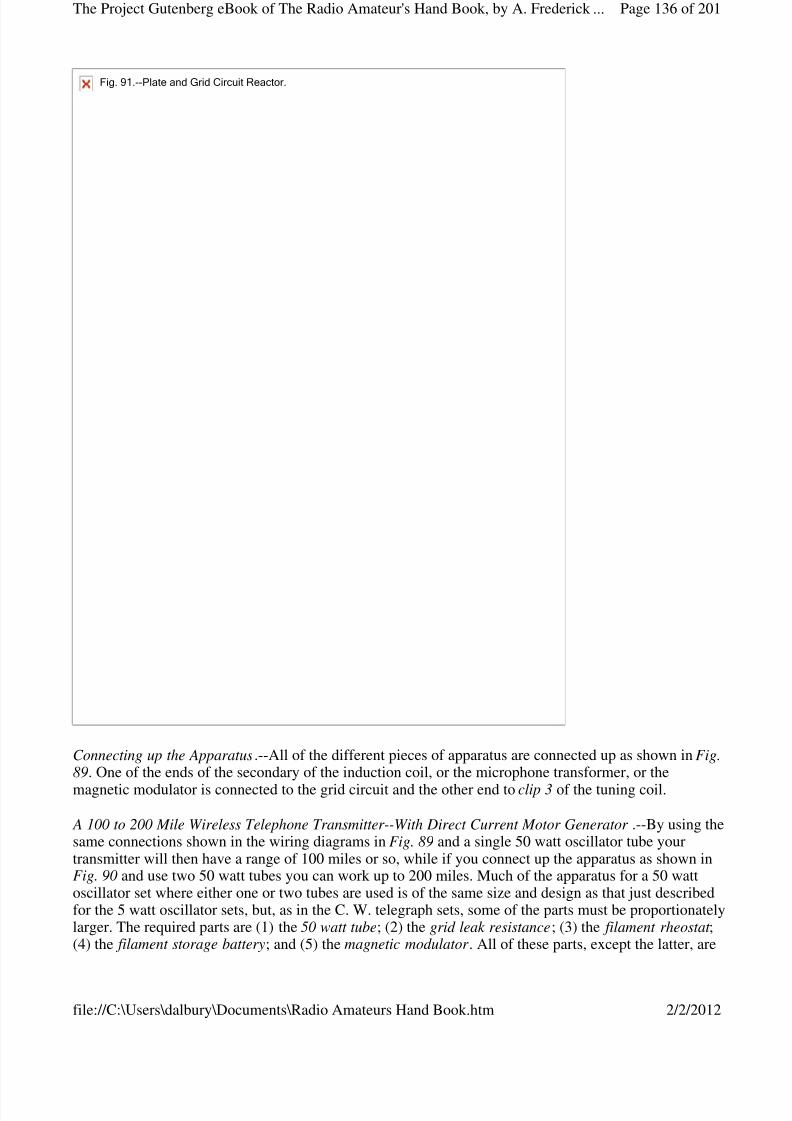
8/3/2019 Radio Amateurs Hand Book
http://slidepdf.com/reader/full/radio-amateurs-hand-book 136/201
Connecting up the Apparatus.--All of the different pieces of apparatus are connected up as shown in Fig.89. One of the ends of the secondary of the induction coil, or the microphone transformer, or the
magnetic modulator is connected to the grid circuit and the other end to clip 3 of the tuning coil.
A 100 to 200 Mile Wireless Telephone Transmitter--With Direct Current Motor Generator .--By using thesame connections shown in the wiring diagrams in Fig. 89 and a single 50 watt oscillator tube yourtransmitter will then have a range of 100 miles or so, while if you connect up the apparatus as shown inFig. 90 and use two 50 watt tubes you can work up to 200 miles. Much of the apparatus for a 50 wattoscillator set where either one or two tubes are used is of the same size and design as that just describedfor the 5 watt oscillator sets, but, as in the C. W. telegraph sets, some of the parts must be proportionatelylarger. The required parts are (1) the 50 watt tube; (2) the grid leak resistance; (3) the filament rheostat ;(4) the filament storage battery; and (5) the magnetic modulator . All of these parts, except the latter, are
Fig.91.--PlateandGridCircuitReactor.
Page 136 of 201The Project Gutenberg eBook of The Radio Amateur's Hand Book, by A. Frederick ...
2/2/2012file://C:\Users\dalbury\Documents\Radio Amateurs Hand Book.htm
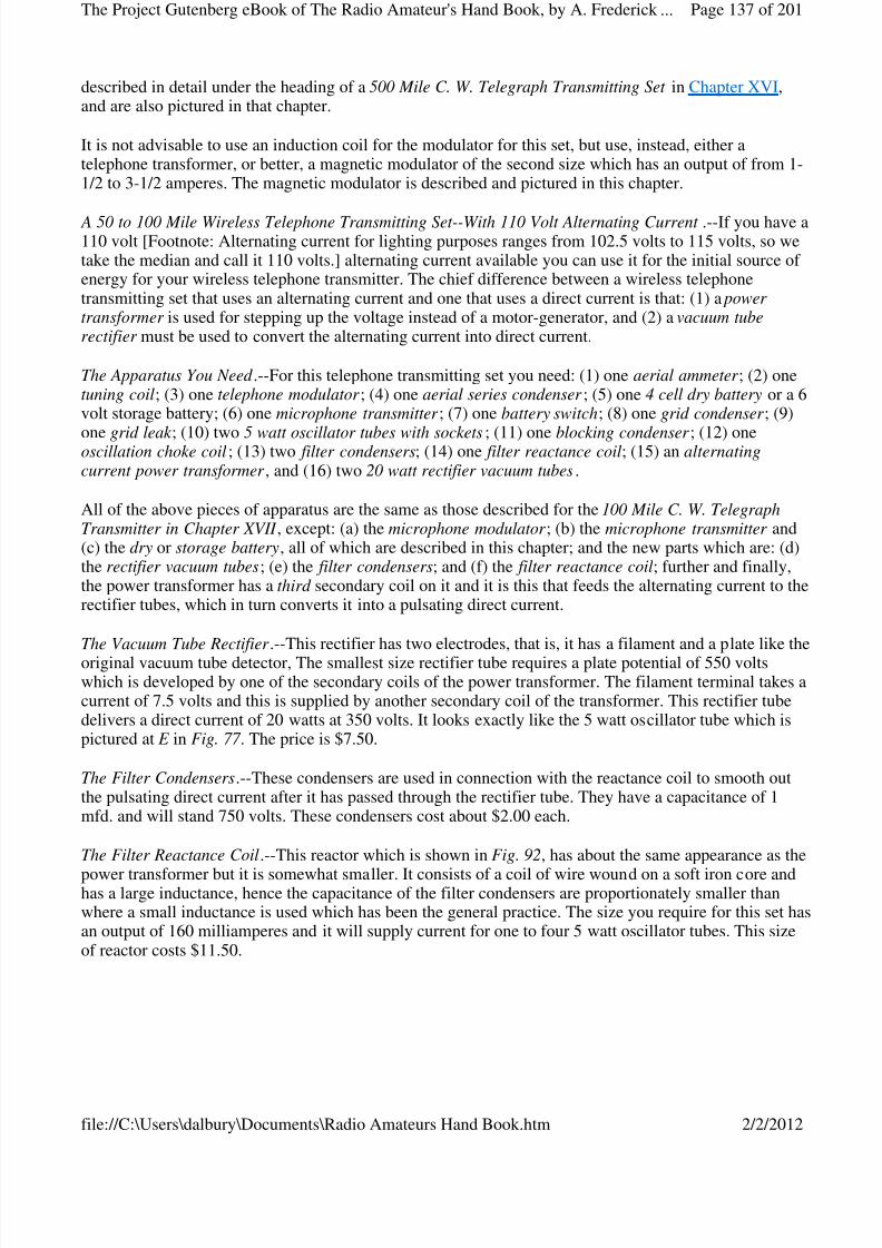
8/3/2019 Radio Amateurs Hand Book
http://slidepdf.com/reader/full/radio-amateurs-hand-book 137/201
described in detail under the heading of a 500 Mile C. W. Telegraph Transmitting Set in Chapter XVI,and are also pictured in that chapter.
It is not advisable to use an induction coil for the modulator for this set, but use, instead, either atelephone transformer, or better, a magnetic modulator of the second size which has an output of from 1-1/2 to 3-1/2 amperes. The magnetic modulator is described and pictured in this chapter.
A 50 to 100 Mile Wireless Telephone Transmitting Set--With 110 Volt Alternating Current .--If you have a110 volt [Footnote: Alternating current for lighting purposes ranges from 102.5 volts to 115 volts, so wetake the median and call it 110 volts.] alternating current available you can use it for the initial source of energy for your wireless telephone transmitter. The chief difference between a wireless telephonetransmitting set that uses an alternating current and one that uses a direct current is that: (1) a power transformer is used for stepping up the voltage instead of a motor-generator, and (2) a vacuum tuberectifier must be used to convert the alternating current into direct current.
The Apparatus You Need .--For this telephone transmitting set you need: (1) one aerial ammeter ; (2) onetuning coil; (3) one telephone modulator ; (4) one aerial series condenser ; (5) one 4 cell dry battery or a 6volt storage battery; (6) one microphone transmitter ; (7) one battery switch; (8) one grid condenser ; (9)
one grid leak ; (10) two 5 watt oscillator tubes with sockets; (11) one blocking condenser ; (12) oneoscillation choke coil; (13) two filter condensers; (14) one filter reactance coil; (15) an alternatingcurrent power transformer , and (16) two 20 watt rectifier vacuum tubes.
All of the above pieces of apparatus are the same as those described for the 100 Mile C. W. TelegraphTransmitter in Chapter XVII , except: (a) the microphone modulator ; (b) the microphone transmitter and(c) the dry or storage battery, all of which are described in this chapter; and the new parts which are: (d)the rectifier vacuum tubes; (e) the filter condensers; and (f) the filter reactance coil; further and finally,the power transformer has a third secondary coil on it and it is this that feeds the alternating current to therectifier tubes, which in turn converts it into a pulsating direct current.
The Vacuum Tube Rectifier .--This rectifier has two electrodes, that is, it has a filament and a plate like theoriginal vacuum tube detector, The smallest size rectifier tube requires a plate potential of 550 voltswhich is developed by one of the secondary coils of the power transformer. The filament terminal takes acurrent of 7.5 volts and this is supplied by another secondary coil of the transformer. This rectifier tubedelivers a direct current of 20 watts at 350 volts. It looks exactly like the 5 watt oscillator tube which ispictured at E in Fig. 77 . The price is $7.50.
The Filter Condensers.--These condensers are used in connection with the reactance coil to smooth outthe pulsating direct current after it has passed through the rectifier tube. They have a capacitance of 1mfd. and will stand 750 volts. These condensers cost about $2.00 each.
The Filter Reactance Coil.--This reactor which is shown in Fig. 92, has about the same appearance as the
power transformer but it is somewhat smaller. It consists of a coil of wire wound on a soft iron core andhas a large inductance, hence the capacitance of the filter condensers are proportionately smaller thanwhere a small inductance is used which has been the general practice. The size you require for this set hasan output of 160 milliamperes and it will supply current for one to four 5 watt oscillator tubes. This sizeof reactor costs $11.50.
Page 137 of 201The Project Gutenberg eBook of The Radio Amateur's Hand Book, by A. Frederick ...
2/2/2012file://C:\Users\dalbury\Documents\Radio Amateurs Hand Book.htm
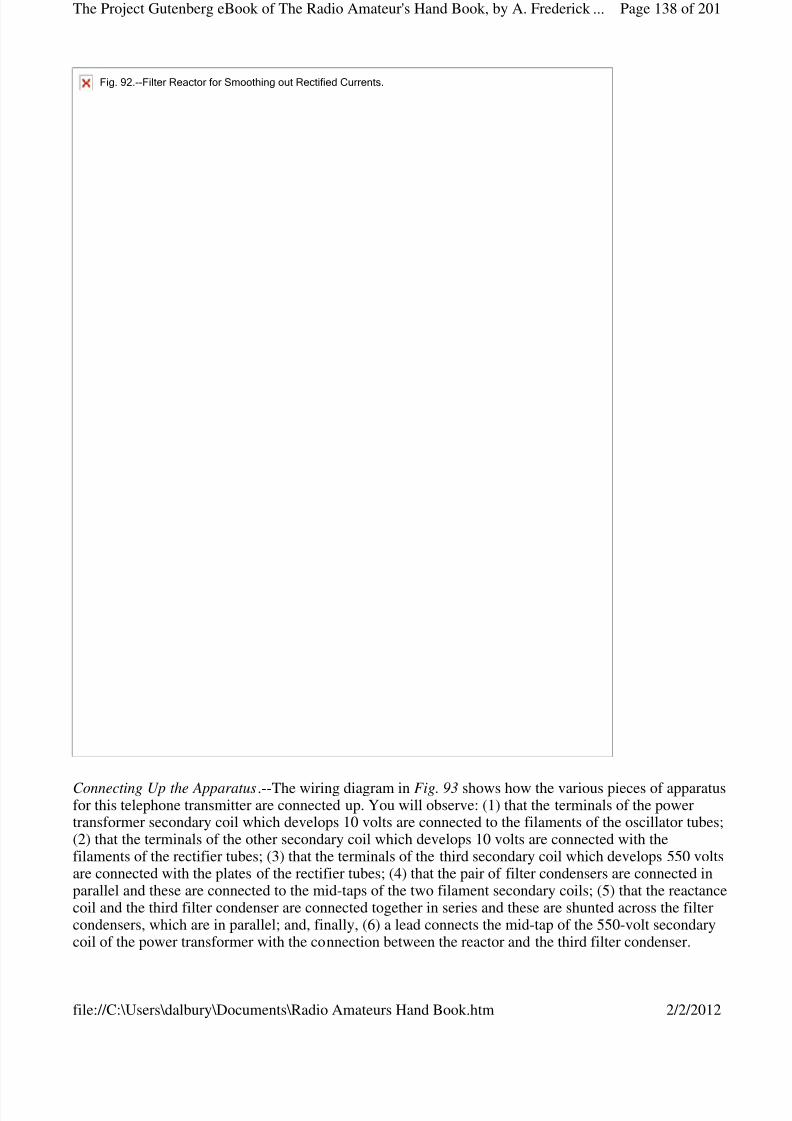
8/3/2019 Radio Amateurs Hand Book
http://slidepdf.com/reader/full/radio-amateurs-hand-book 138/201
Connecting Up the Apparatus.--The wiring diagram in Fig. 93 shows how the various pieces of apparatusfor this telephone transmitter are connected up. You will observe: (1) that the terminals of the powertransformer secondary coil which develops 10 volts are connected to the filaments of the oscillator tubes;(2) that the terminals of the other secondary coil which develops 10 volts are connected with thefilaments of the rectifier tubes; (3) that the terminals of the third secondary coil which develops 550 voltsare connected with the plates of the rectifier tubes; (4) that the pair of filter condensers are connected inparallel and these are connected to the mid-taps of the two filament secondary coils; (5) that the reactancecoil and the third filter condenser are connected together in series and these are shunted across the filtercondensers, which are in parallel; and, finally, (6) a lead connects the mid-tap of the 550-volt secondarycoil of the power transformer with the connection between the reactor and the third filter condenser.
Fig.92.--FilterReactorforSmoothingoutRectifiedCurrents.
Page 138 of 201The Project Gutenberg eBook of The Radio Amateur's Hand Book, by A. Frederick ...
2/2/2012file://C:\Users\dalbury\Documents\Radio Amateurs Hand Book.htm
8/3/2019 Radio Amateurs Hand Book
http://slidepdf.com/reader/full/radio-amateurs-hand-book 139/201
A 100 to 200 Mile Wireless Telephone Transmitting Set--With 110 Volt Alternating Current .--Thistelephone transmitter is built up of exactly the same pieces of apparatus and connected up in precisely thesame way as the one just described and shown in Fig. 93.
Apparatus Required .--The only differences between this and the preceding transmitter are: (1) themagnetic modulator , if you use one, should have an output of 3-1/2 to 5 amperes; (2) you will need two50 watt oscillator tubes with sockets; (3) two 150 watt rectifier tubes with sockets; (4) an aerial ammeter that reads to 5 amperes; (5) three 1 mfd. filter condensers in parallel; (6) two filter condensers of 1 mfd.capacitance that will stand 1750 volts; and (6) a 300 milliampere filter reactor .
The apparatus is wired up as shown in Fig. 93.
CHAPTER XIX
THE OPERATION OF VACUUM TUBE TRANSMITTERS
The three foregoing chapters explained in detail the design and construction of (1) two kinds of C. W.telegraph transmitters, and (2) two kinds of wireless telephone transmitters, the difference between thembeing whether they used ( A) a direct current, or ( B) an alternating current as the initial source of energy.Of course there are other differences between those of like types as, for instance, the apparatus andconnections used (a) in the key circuits, and (b) in the microphone circuits. But in all of the transmittersdescribed of whatever type or kind the same fundamental device is used for setting up sustainedoscillations and this is the vacuum tube.
The Operation of the Vacuum Tube Oscillator .--The operation of the vacuum tube in producing sustainedoscillations depends on (1) the action of the tube as a valve in setting up the oscillations in the first placeand (2) the action of the grid in amplifying the oscillations thus set up, both of which we explained inChapter XIV. In that chapter it was also pointed out that a very small change in the grid potential causes acorresponding and larger change in the amount of current flowing from the plate to the filament; and thatif a vacuum tube is used for the production of oscillations the initial source of current must have a highvoltage, in fact the higher the plate voltage the more powerful will be the oscillations.
Fig93.--100to200MileWirelessTelephoneTransmitter.
Page 139 of 201The Project Gutenberg eBook of The Radio Amateur's Hand Book, by A. Frederick ...
2/2/2012file://C:\Users\dalbury\Documents\Radio Amateurs Hand Book.htm

8/3/2019 Radio Amateurs Hand Book
http://slidepdf.com/reader/full/radio-amateurs-hand-book 140/201
To understand how oscillations are set up by a vacuum tube when a direct current is applied to it, take alook at the simple circuits shown in Fig. 94. Now when you close the switch the voltage from the batterycharges the condenser and keeps it charged until you open it again; the instant you do this the condenserdischarges through the circuit which includes it and the inductance coil, and the discharge of a condenseris always oscillatory.
Where an oscillator tube is included in the circuits as shown at A and B in Fig. 94, the grid takes the placeof the switch and any slight change in the voltage of either the grid or the plate is sufficient to start a trainof oscillations going. As these oscillations surge through the tube the positive parts of them flow from theplate to the filament and these carry more of the direct current with them.
To make a tube set up powerful oscillations then, it is only necessary that an oscillation circuit shall beprovided which will feed part of the oscillations set up by the tube back to the grid circuit and when thisis done the oscillations will keep on being amplified until the tube reaches the limit of its output.
(A)and(B)Fig.94.OperationofVacuumTubeOscillators.
Page 140 of 201The Project Gutenberg eBook of The Radio Amateur's Hand Book, by A. Frederick ...
2/2/2012file://C:\Users\dalbury\Documents\Radio Amateurs Hand Book.htm
8/3/2019 Radio Amateurs Hand Book
http://slidepdf.com/reader/full/radio-amateurs-hand-book 141/201
The Operation of C. W. Telegraph Transmitters With Direct Current--Short Distance C. W. Transmitter .--In the transmitter shown in the wiring diagram in Fig. 76 the positive part of the 110 volt direct currentis carried down from the lamp socket through one side of the panel cut-out, thence through the choke coiland to the plate of the oscillator tube, when the latter is charged to the positive sign. The negative part of the 110 volt direct current then flows down the other wire to the filament so that there is a difference of potential between the plate and the filament of 110 volts. Now when the 6-volt battery current is switchedon the filament is heated to brilliancy, and the electrons thrown off by it form a conducting path betweenit and the plate; the 110 volt current then flows from the latter to the former.
Now follow the wiring from the plate over to the blocking condenser, thence to clip 3 of the tuning coil,through the turns of the latter to clip 2 and over to the filament and, when the latter is heated, you have aclosed oscillation circuit . The oscillations surging in the latter set up other and like oscillations in thetuning coil between the end of which is connected with the grid, the aerial and the clip 2, and these surgethrough the circuit formed by this portion of the coil, the grid condenser and the filament; this is theamplifying circuit and it corresponds to the regenerative circuit of a receiving set.
When oscillations are set up in it the grid is alternately charged to the positive and negative signs. Thesereversals of voltage set up stronger and ever stronger oscillations in the plate circuit as before explained.Not only do the oscillations surge in the closed circuits but they run to and fro on the aerial wire whentheir energy is radiated in the form of electric waves. The oscillations are varied by means of thetelegraph key which is placed in the grid circuit as shown in Fig. 76 .
The Operation of the Key Circuit .--The effect in a C. W. transmitter when a telegraph key is connected inseries with a buzzer and a battery and these are shunted around the condenser in the grid circuit, is torapidly change the wave form of the sustained oscillations, and hence, the length of the waves that aresent out. While no sound can be heard in the headphones at the receiving station so long as the points of
the key are not in contact, when they are in contact the oscillations are modulated and sounds are heard inthe headphones that correspond to the frequency of the buzzer in the key circuit.
The Operation of C. W. Telegraph Transmitters with Direct Current .--The chief differences between thelong distance sets which use a direct current, i.e., those described in Chapter XVI, and the short distancetransmitting sets are that the former use: (1) a motor-generator set for changing the low voltage directcurrent into high voltage direct current, and (2) a chopper in the key circuit. The way the motor-generatorchanges the low- into high-voltage current has been explained in Chapter XVI.
The chopper interrupts the oscillations surging through the grid circuit at a frequency that the ear can
(C)Fig.94.--HowaDirectCurrentSetsupOscillations.
Page 141 of 201The Project Gutenberg eBook of The Radio Amateur's Hand Book, by A. Frederick ...
2/2/2012file://C:\Users\dalbury\Documents\Radio Amateurs Hand Book.htm
8/3/2019 Radio Amateurs Hand Book
http://slidepdf.com/reader/full/radio-amateurs-hand-book 142/201

8/3/2019 Radio Amateurs Hand Book
http://slidepdf.com/reader/full/radio-amateurs-hand-book 143/201
set up by one tube and the beginning of the oscillations set up by the other tube. In other words theseoscillations are sustained but as in the case of those of a single tube, their amplitude rises and falls. Thiskind of a set is called a full wave rectification transmitter .
The waves radiated by this transmitter can be received by either a crystal detector or a plain vacuum-tubedetector but the heterodyne receptor will give you better results than either of the foregoing types.
The Operation of Wireless Telephone Transmitters with Direct Current--Short Distance Transmitter .--The operation of this short distance wireless telephone transmitter, a wiring diagram of which is shown inFig. 85 is exactly the same as that of the Direct Current Short Distance C. W. Telegraph Transmitter already explained in this chapter. The only difference in the operation of these sets is the substitution of the microphone transmitter for the telegraph key.
The Microphone Transmitter .--The microphone transmitter that is used to vary, or modulate, thesustained oscillations set up by the oscillator tube and circuits is shown in Fig. 84. By referring to thediagram at A in this figure you will readily understand how it operates. When you speak into themouthpiece the sound waves, which are waves in the air, impinge upon the diaphragm and these set itinto vibration--that is, they make it move to and fro.
When the diaphragm moves toward the back of the transmitter it forces the carbon granules that are in thecup closer together; this lowers their resistance and allows more current from the battery to flow throughthem; when the pressure of the air waves is removed from the diaphragm it springs back toward themouth-piece and the carbon granules loosen up when the resistance offered by them is increased and lesscurrent can flow through them. Where the oscillation current in the aerial wire is small the transmitter canbe connected directly in series with the latter when the former will surge through it. As you speak into themicrophone transmitter its resistance is varied and the current strength of the oscillations is variedaccordingly.
The Operation of Wireless Telephone Transmitters with Direct Current--Long Distance Transmitters.--Inthe wireless telephone transmitters for long distance work which were shown and described in thepreceding chapter a battery is used to energize the microphone transmitter, and these two elements areconnected in series with a microphone modulator . This latter device may be either (1) a telephoneinduction coil, (2) a microphone transformer , or (3) a magnetic modulator ; the first two of these devicesstep-up the voltage of the battery current and the amplified voltage thus developed is impressed on theoscillations that surge through the closed oscillation circuit or the aerial wire system according to theplace where you connect it. The third device works on a different principle and this will be described alittle farther along.
The Operation of Microphone Modulators--The Induction Coil.--This device is really a miniaturetransformer, see A in Fig. 86 , and its purpose is to change the 6 volt direct current that flows through themicrophone into 100 volts alternating current; in turn, this is impressed on the oscillations that are
surging in either (1) the grid circuit as shown at A in Fig. 89, and in Fig. 90, (2) the aerial wire system, asshown at B in Fig. 89 and Fig. 93. When the current from the battery flows through the primary coil itmagnetizes the soft iron core and as the microphone varies the strength of the current the high voltagealternating currents set up in the secondary coil of the induction coil are likewise varied, when they areimpressed upon and modulate the oscillating currents.
The Microphone Transformer .--This is an induction coil that is designed especially for wireless telephonemodulation. The iron core of this transformer is also of the open magnetic circuit type, see A in Fig. 87 ,and the ratio of the turns [Footnote: See Chapter VI] of the primary and the secondary coil is such thatwhen the secondary current is impressed upon either the grid circuit or the aerial wire system it controls
Page 143 of 201The Project Gutenberg eBook of The Radio Amateur's Hand Book, by A. Frederick ...
2/2/2012file://C:\Users\dalbury\Documents\Radio Amateurs Hand Book.htm
8/3/2019 Radio Amateurs Hand Book
http://slidepdf.com/reader/full/radio-amateurs-hand-book 144/201
the oscillations flowing through it with the greatest efficiency.
The Magnetic Modulator .--This piece of apparatus is also called a magnetic amplifier . The iron core isformed of very thin plates, or laminations as they are called, and this permits high-frequency oscillationsto surge in a coil wound on it. In this transformer, see A in Fig. 88, the current flowing through themicrophone varies the magnetic permeability of the soft iron core by the magnetic saturation of the latter.Since the microphone current is absolutely distinct from the oscillating currents surging through the coil
of the transformer a very small direct current flowing through a coil on the latter will vary or modulatevery large oscillating currents surging through the former. It is shown connected in the aerial wire systemat A in Fig. 88, and in Fig. 93.
Operation of the Vacuum Tube as a Modulator .--Where a microphone modulator of the induction coil ormicrophone transformer type is connected in the grid circuit or aerial wire system the modulation is notvery effective, but by using a second tube as a modulator , as shown in Fig. 90, an efficient degree of modulation can be had. Now there are two methods by which a vacuum tube can be used as a modulatorand these are: (1) by the absorption of the energy of the current set up by the oscillator tube, and (2) byvarying the direct current that energizes the plate of the oscillator tube.
The first of these two methods is not used because it absorbs the energy of the oscillating currentproduced by the tube and it is therefore wasteful. The second method is an efficient one, as the directcurrent is varied before it passes into the oscillator tube. This is sufficient reason for describing only thesecond method. The voltage of the grid of the modulator tube is varied by the secondary coil of theinduction coil or microphone transformer, above described. In this way the modulator tube acts like avariable resistance but it amplifies the variations impressed on the oscillations set up by the oscillatortube. As the magnetic modulator does the same thing a vacuum tube used as a modulator is not neededwhere the former is employed. For this reason a magnetic modulator is the cheapest in the long run.
The Operation of Wireless Telephone Transmitters with Alternating Current .--Where an initialalternating current is used for wireless telephony, the current must be rectified first and then smoothedout before passing into the oscillator tube to be converted into oscillations. Further so that the oscillations
will be sustained, two oscillator tubes must be used, and, finally, in order that the oscillations may notvary in amplitude the alternating current must be first changed into direct current by a pair of rectifiervacuum tubes, as shown in Fig. 93. When this is done the plates will be positively charged alternatelywith every reversal of the current in which case there will be no break in the continuity of the oscillationsset up and therefore in the waves that are sent out.
The Operation of Rectifier Vacuum Tubes.--The vacuum tube rectifier is simply a two electrode vacuumtube. The way in which it changes a commercial alternating current into pulsating direct current is thesame as that in which a two electrode vacuum tube detector changes an oscillating current into pulsatingdirect currents and this has been explained in detail under the heading of The Operation of a Two Electrode Vacuum Tube Detector in Chapter XII. In the C. W. Telegraph Transmitting Sets described in
Chapter XVII, the oscillator tubes act as rectifiers as well as oscillators but for wireless telephony thealternating current must be rectified first so that a continuous direct current will result.
The Operation of Reactors and Condensers.--A reactor is a single coil of wire wound on an iron core, seeFig. 90 and A in Fig. 91, and it should preferably have a large inductance. The reactor for the plate andgrid circuit of a wireless telephone transmitter where one or more tubes are used as modulators as shownin the wiring diagram in Fig. 90, and the filter reactor shown in Fig. 92, operate in the same way.
When an alternating current flows through a coil of wire the reversals of the current set up a counter electromotive force in it which opposes, that is reacts, on the current, and the higher the frequency of the
Page 144 of 201The Project Gutenberg eBook of The Radio Amateur's Hand Book, by A. Frederick ...
2/2/2012file://C:\Users\dalbury\Documents\Radio Amateurs Hand Book.htm
8/3/2019 Radio Amateurs Hand Book
http://slidepdf.com/reader/full/radio-amateurs-hand-book 145/201
current the greater will be the reactance. When the positive half of an alternating current is made to flowthrough a large resistance the current is smoothed out but at the same time a large amount of its energy isused up in producing heat.
But when the positive half of an alternating current is made to flow through a large inductance it acts likea large resistance as before and likewise smooths out the current, but none of its energy is wasted in heatand so a coil having a large inductance, which is called an inductive reactance, or just reactor for short, is
used to smooth out, or filter, the alternating current after it has been changed into a pulsating directcurrent by the rectifier tubes.
A condenser also has a reactance effect on an alternating current but different from an induction coil thelower the frequency the greater will be the reactance. For this reason both a filter reactor and filter condensers are used to smooth out the pulsating direct currents.
CHAPTER XX
HOW TO MAKE A RECEIVING SET FOR $5.00 OR LESS
In the chapters on Receptors you have been told how to build up high-grade sets. But there are thousandsof boys, and, probably, not a few men, who cannot afford to invest $25.00, more or less, in a receiving setand would like to experiment in a small way.
The following set is inexpensive, and with this cheap, little portable receptor you can get the Morse codefrom stations a hundred miles distant and messages and music from broadcasting stations if you do notlive too far away from them. All you need for this set are: (1) a crystal detector , (2) a tuning coil and (3)an earphone. You can make a crystal detector out of a couple of binding posts, a bit of galena and a pieceof brass wire, or, better, you can buy one all ready to use for 50 cents.
The Crystal Detector .--This is known as the Rasco baby detector and it is made and sold by the RadioSpecialty Company, 96 Park Place, New York City. It is shown in Fig. 96 . The base is made of black
composition and on it is mounted a standard in which a rod slides and on one end of this there is fixed ahard rubber adjusting knob while the other end carries a thin piece of phosphor-bronze wire, called a cat-whisker To secure the galena crystal in the cup you simply unscrew the knurled cap, place it in the cavityof the post and screw the cap back on again. The free end of the cat-whisker wire is then adjusted so thatit will rest lightly on the exposed part of the galena.
Photograph unavailable
Wireless Receptor, the size of a Safety Match Box. A Youthful Genius in the person of Kenneth R.Hinman, Who is only twelve years old, has made a Wireless Receiving Set that fits neatly into aSafety Match Box. With this Instrument and a Pair of Ordinary Receivers, He is able to catch not
only Code Messages but the regular Broadcasting Programs from Stations Twenty and ThirtyMiles Distant.
Page 145 of 201The Project Gutenberg eBook of The Radio Amateur's Hand Book, by A. Frederick ...
2/2/2012file://C:\Users\dalbury\Documents\Radio Amateurs Hand Book.htm
8/3/2019 Radio Amateurs Hand Book
http://slidepdf.com/reader/full/radio-amateurs-hand-book 146/201
The Tuning Coil.--You will have to make this tuning coil, which you can do at a cost of less than $1.00,as the cheapest tuning coil you can buy costs at least $3.00, and we need the rest of our $5.00 to invest inthe earphone. Get a cardboard tube, such as is used for mailing purposes, 2 inches in diameter and 3inches long, see A in Fig. 97 . Now wind on 250 turns of No. 40 Brown and Sharpe gauge plain enameled magnet wire. You can use No. 40 double cotton covered magnet wire, in which case you will have toshellac the tube and the wire after you get it on.
As you wind on the wire take off a tap at every 15th turn, that is, scrape the wire and solder on a pieceabout 7 inches long, as shown in Fig. 99; and do this until you have 6 taps taken off. Instead of leaving
Fig.96.--RascoBabyCrystalDetector.
Fig.97.--HowtheTuningCoilisMade.
Page 146 of 201The Project Gutenberg eBook of The Radio Amateur's Hand Book, by A. Frederick ...
2/2/2012file://C:\Users\dalbury\Documents\Radio Amateurs Hand Book.htm
8/3/2019 Radio Amateurs Hand Book
http://slidepdf.com/reader/full/radio-amateurs-hand-book 147/201
the wires outside of the tube bring them to the inside of it and then out through one of the open ends.Now buy a round wood-base switch with 7 contact points on it as shown at B in Fig. 97 . This will costyou 25 or 50 cents.
The Headphone.--An ordinary Bell telephone receiver is of small use for wireless work as it is wound totoo low a resistance and the diaphragm is much too thick. If you happen to have a Bell phone you canrewind it with No. 40 single covered silk magnet wire, or enameled wire of the same size, when its
sensitivity will be very greatly improved. Then you must get a thin diaphragm and this should not beenameled, as this tends to dampen the vibrations of it. You can get a diaphragm of the right kind for 5cents.
The better way, though, is to buy an earphone made especially for wireless work. You can get one woundto 1000 ohms resistance for $1.75 and this price includes a cord. [Footnote: This is Mesco, No. 470wireless phone. Sold by the Manhattan Electrical Supply Co., Park Place, N.Y.C.] For $1.00 extra youcan get a head-band for it, and then your phone will look like the one pictured in Fig. 98.
How to Mount the Parts.--Now mount the coil on a wood base, 1/2 or 1 inch thick, 3-1/2 inches wide and5-1/2 inches long, and then connect one end of the coil to one of the end points on the switch, andconnect each succeeding tap to one of the switch points, as shown schematically in Fig. 99 anddiagrammatically in Fig. 100. This done, screw the switch down to the base. Finally screw the detector tothe base and screw two binding posts in front of the coil. These are for the earphone.
Fig.98.--Mesco1000OhmHeadSet.
Page 147 of 201The Project Gutenberg eBook of The Radio Amateur's Hand Book, by A. Frederick ...
2/2/2012file://C:\Users\dalbury\Documents\Radio Amateurs Hand Book.htm
8/3/2019 Radio Amateurs Hand Book
http://slidepdf.com/reader/full/radio-amateurs-hand-book 148/201
Fig.99.--SchematicLayoutof$5.00ReceivingSet.
Page 148 of 201The Project Gutenberg eBook of The Radio Amateur's Hand Book, by A. Frederick ...
2/2/2012file://C:\Users\dalbury\Documents\Radio Amateurs Hand Book.htm
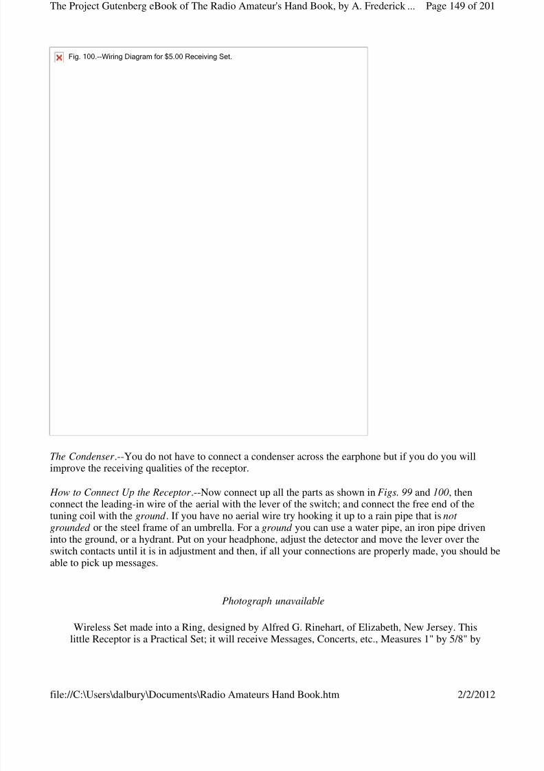
8/3/2019 Radio Amateurs Hand Book
http://slidepdf.com/reader/full/radio-amateurs-hand-book 149/201

8/3/2019 Radio Amateurs Hand Book
http://slidepdf.com/reader/full/radio-amateurs-hand-book 150/201
APPENDIX
USEFUL INFORMATION
ABBREVIATIONS OF UNITS
Unit Abbreviation
ampere amp.ampere-hours amp.-hr.centimeter cm.centimeter-gram-second c.g.s.cubic centimeters cm.^3cubic inches cu. in.cycles per second ~degrees Centigrade °C.degrees Fahrenheit °F.feet ft.foot-pounds ft.-lb.grams g.henries h.inches in.kilograms kg.kilometers km.kilowatts kw.kilowatt-hours kw.-hr.kilovolt-amperes kv.-a.meters m.
microfarads [Greek: mu]f.micromicrofarads [Greek: mu mu]f.millihenries mh.millimeters mm.pounds lb.seconds sec.square centimeters cm.^2square inches sq. in.volts v.watts w.
PREFIXES USED WITH METRIC SYSTEM UNITS
Prefix Abbreviation Meaning
micro [Greek: mu]. 1 millionthmilli m. 1 thousandthcenti c. 1 hundredthdeci d. 1 tenthdeka dk. 10hekto h. 1 hundredkilo k. 1 thousandmega m. 1 million
7/8". An ordinary Umbrella is used as an Aerial.
Page 150 of 201The Project Gutenberg eBook of The Radio Amateur's Hand Book, by A. Frederick ...
2/2/2012file://C:\Users\dalbury\Documents\Radio Amateurs Hand Book.htm

8/3/2019 Radio Amateurs Hand Book
http://slidepdf.com/reader/full/radio-amateurs-hand-book 151/201
SYMBOLS USED FOR VARIOUS QUANTITIES
Quantity Symbol
capacitance C
conductance g
coupling co-efficient k
current, instantaneous i
current, effective value I
decrement [Greek: delta]
dielectric constant [Greek: alpha]
electric field intensity [Greek: epsilon]
electromotive force,
instantaneous value E
Symbolsforquantities
Page 151 of 201The Project Gutenberg eBook of The Radio Amateur's Hand Book, by A. Frederick ...
2/2/2012file://C:\Users\dalbury\Documents\Radio Amateurs Hand Book.htm
8/3/2019 Radio Amateurs Hand Book
http://slidepdf.com/reader/full/radio-amateurs-hand-book 152/201
electromotive force,
effective value F
energy W
force F
frequency f
frequency x 2[Greek: pi] [Greek: omega]
impedance Z
inductance, self L
inductance, mutual M
magnetic field intensity A
magnetic flux [Greek: Phi]
magnetic induction B
period of a complete
oscillation T
potential difference V
quantity of electricity Q
ratio of the
circumference of a
circle to its diameter
=3.1416 [Greek: pi]
reactance X
resistance R
time t
velocity v
velocity of light c
wave length [Greek: lambda]
wave length in meters [Greek: lambda]m
work W
permeability [Greek: mu]
Square root [Math: square root]
Page 152 of 201The Project Gutenberg eBook of The Radio Amateur's Hand Book, by A. Frederick ...
2/2/2012file://C:\Users\dalbury\Documents\Radio Amateurs Hand Book.htm
8/3/2019 Radio Amateurs Hand Book
http://slidepdf.com/reader/full/radio-amateurs-hand-book 153/201
TABLE OF ENAMELED WIRE
No. of Turns Turns Ohms perWire, per per Cubic InchB.& S. Linear Square ofGauge Inch Inch Winding
20 30 885 .748
22 37 1400 1.8824 46 2160 4.6126 58 3460 11.8028 73 5400 29.2030 91 8260 70.9032 116 21,000 7547.0034 145 13,430 2968.0036 178 31,820 1098.0038 232 54,080 456.0040 294 86,500 183.00
TABLE OF FREQUENCY AND WAVE LENGTHS
W. L.--Wave Lengths in Meters.F.--Number of Oscillations per Second.O. or square root L. C. is called Oscillation Constant.C.--Capacity in Microfarads.L.--Inductance in Centimeters.1000 Centimeters = 1 Microhenry.
W.L. F O L.C.50 6,000,000 .839 .7039100 3,000,000 1.68 2.82150 2,000,000 2.52 6.35200 1,500,000 3.36 11.29250 1,200,000 4.19 17.55
300 1,000,000 5.05 25.30350 857,100 5.87 34.46400 750,000 6.71 45.03450 666,700 7.55 57.00500 600,000 8.39 70.39550 545,400 9.23 85.19600 500,000 10.07 101.41700 428,600 11.74 137.83800 375,000 13.42 180.10900 333,300 15.10 228.01
1,000 300,000 16.78 281.571,100 272,730 18.45 340.401,200 250,000 20.13 405.20
1,300 230,760 21.81 475.701,400 214,380 23.49 551.801,500 200,000 25.17 633.501,600 187,500 26.84 720.401,700 176,460 28.52 813.401,800 166,670 30.20 912.001,900 157,800 31.88 1,016.402,000 150,000 33.55 1,125.602,100 142,850 35.23 1,241.202,200 136,360 36.91 1,362.402,300 130,430 38.59 1,489.302,400 125,000 40.27 1,621.80
Page 153 of 201The Project Gutenberg eBook of The Radio Amateur's Hand Book, by A. Frederick ...
2/2/2012file://C:\Users\dalbury\Documents\Radio Amateurs Hand Book.htm
8/3/2019 Radio Amateurs Hand Book
http://slidepdf.com/reader/full/radio-amateurs-hand-book 154/201
2,500 120,000 41.95 1,759.702,600 115,380 43.62 1,902.602,700 111,110 45.30 2,052.002,800 107,140 46.89 2,207.002,900 103,450 48.66 2,366.303,000 100,000 50.33 2,533.204,000 75,000 67.11 4,504.005,000 60,000 83.89 7,038.00
6,000 50,000 100.7 10,130.007,000 41,800 117.3 13,630.008,000 37,500 134.1 18,000.009,000 33,300 151.0 22,820.0010,000 30,000 167.9 28,150.0011,000 27,300 184.8 34,150.0012,000 25,000 201.5 40,600.0013,000 23,100 218.3 47,600.0014,000 21,400 235.0 55,200.0015,000 20,000 252.0 63,500.0016,000 18,750 269.0 72,300.00
PRONUNCIATION OF GREEK LETTERS
Many of the physical quantities use Greek letters for symbols. The following is the Greek alphabet withthe way the letters are pronounced:
a alphab betag gammad deltae epsilonz zetaae eta
th thetai iotak kappal lambdam mun nux Xi(Zi)o omicronp pir rhos sigmat tau
Greeksymbols
Page 154 of 201The Project Gutenberg eBook of The Radio Amateur's Hand Book, by A. Frederick ...
2/2/2012file://C:\Users\dalbury\Documents\Radio Amateurs Hand Book.htm

8/3/2019 Radio Amateurs Hand Book
http://slidepdf.com/reader/full/radio-amateurs-hand-book 155/201
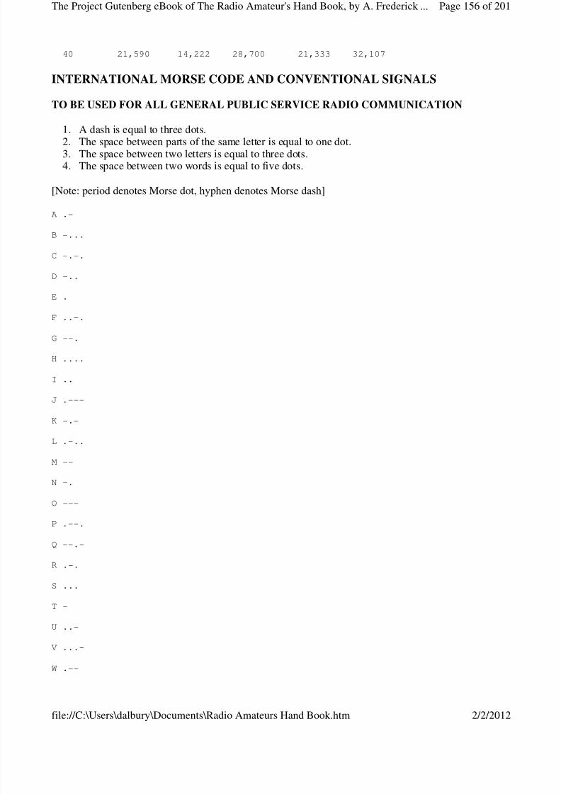
8/3/2019 Radio Amateurs Hand Book
http://slidepdf.com/reader/full/radio-amateurs-hand-book 156/201
40 21,590 14,222 28,700 21,333 32,107
INTERNATIONAL MORSE CODE AND CONVENTIONAL SIGNALS
TO BE USED FOR ALL GENERAL PUBLIC SERVICE RADIO COMMUNICATION
1. A dash is equal to three dots.
2. The space between parts of the same letter is equal to one dot.3. The space between two letters is equal to three dots.4. The space between two words is equal to five dots.
[Note: period denotes Morse dot, hyphen denotes Morse dash]
A .-
B -...
C -.-.
D -..
E .
F ..-.
G --.
H ....
I ..
J .---
K -.-
L .-..
M --
N -.
O ---
P .--.
Q --.-
R .-.
S ...
T -
U ..-
V ...-
W .--
Page 156 of 201The Project Gutenberg eBook of The Radio Amateur's Hand Book, by A. Frederick ...
2/2/2012file://C:\Users\dalbury\Documents\Radio Amateurs Hand Book.htm
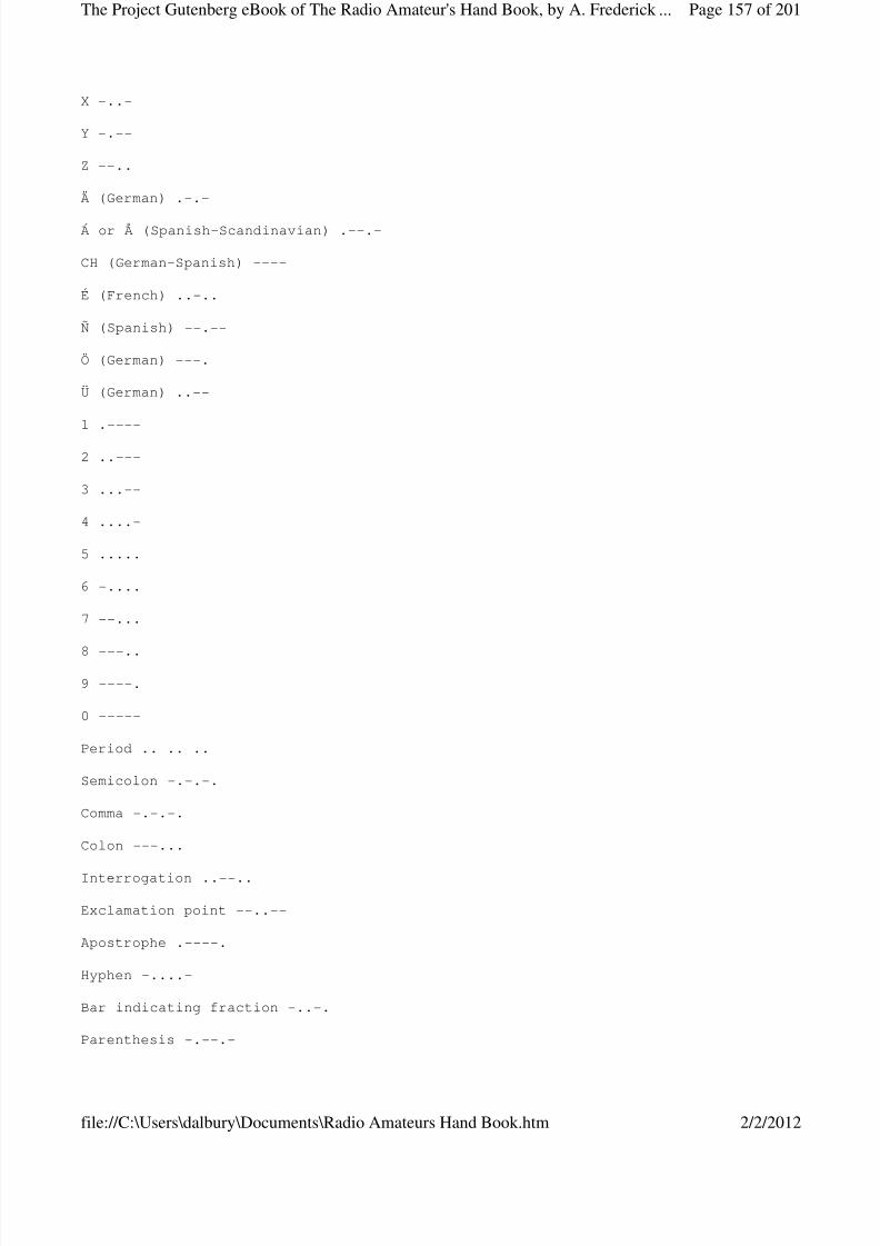
8/3/2019 Radio Amateurs Hand Book
http://slidepdf.com/reader/full/radio-amateurs-hand-book 157/201
X -..-
Y -.--
Z --..
Ä (German) .-.-
Á or Å (Spanish-Scandinavian) .--.-
CH (German-Spanish) ----
É (French) ..-..
Ñ (Spanish) --.--
Ö (German) ---.
Ü (German) ..--
1 .----
2 ..---
3 ...--
4 ....-
5 .....
6 -....
7 --...
8 ---..
9 ----.
0 -----
Period .. .. ..
Semicolon -.-.-.
Comma -.-.-.
Colon ---...
Interrogation ..--..
Exclamation point --..--
Apostrophe .----.
Hyphen -....-
Bar indicating fraction -..-.
Parenthesis -.--.-
Page 157 of 201The Project Gutenberg eBook of The Radio Amateur's Hand Book, by A. Frederick ...
2/2/2012file://C:\Users\dalbury\Documents\Radio Amateurs Hand Book.htm
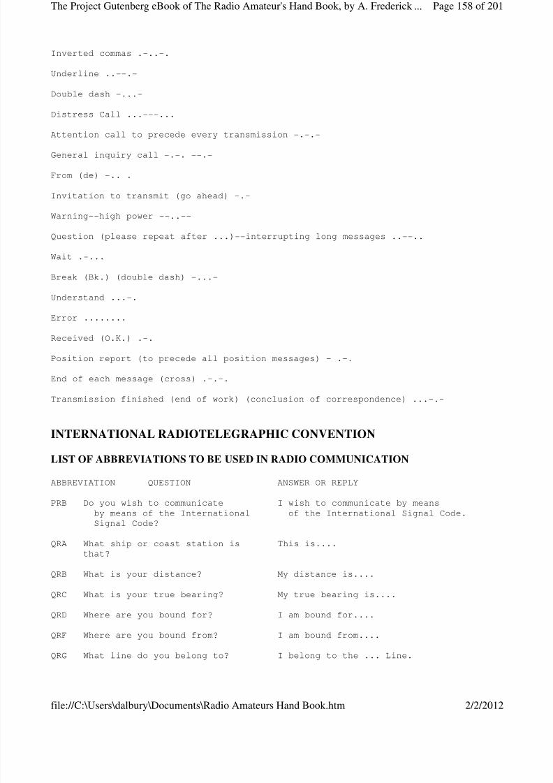
8/3/2019 Radio Amateurs Hand Book
http://slidepdf.com/reader/full/radio-amateurs-hand-book 158/201
Inverted commas .-..-.
Underline ..--.-
Double dash -...-
Distress Call ...---...
Attention call to precede every transmission -.-.-
General inquiry call -.-. --.-
From (de) -.. .
Invitation to transmit (go ahead) -.-
Warning--high power --..--
Question (please repeat after ...)--interrupting long messages ..--..
Wait .-...
Break (Bk.) (double dash) -...-
Understand ...-.
Error ........
Received (O.K.) .-.
Position report (to precede all position messages) - .-.
End of each message (cross) .-.-.
Transmission finished (end of work) (conclusion of correspondence) ...-.-
INTERNATIONAL RADIOTELEGRAPHIC CONVENTION
LIST OF ABBREVIATIONS TO BE USED IN RADIO COMMUNICATION
ABBREVIATION QUESTION ANSWER OR REPLY
PRB Do you wish to communicate I wish to communicate by meansby means of the International of the International Signal Code.Signal Code?
QRA What ship or coast station is This is....that?
QRB What is your distance? My distance is....
QRC What is your true bearing? My true bearing is....
QRD Where are you bound for? I am bound for....
QRF Where are you bound from? I am bound from....
QRG What line do you belong to? I belong to the ... Line.
Page 158 of 201The Project Gutenberg eBook of The Radio Amateur's Hand Book, by A. Frederick ...
2/2/2012file://C:\Users\dalbury\Documents\Radio Amateurs Hand Book.htm
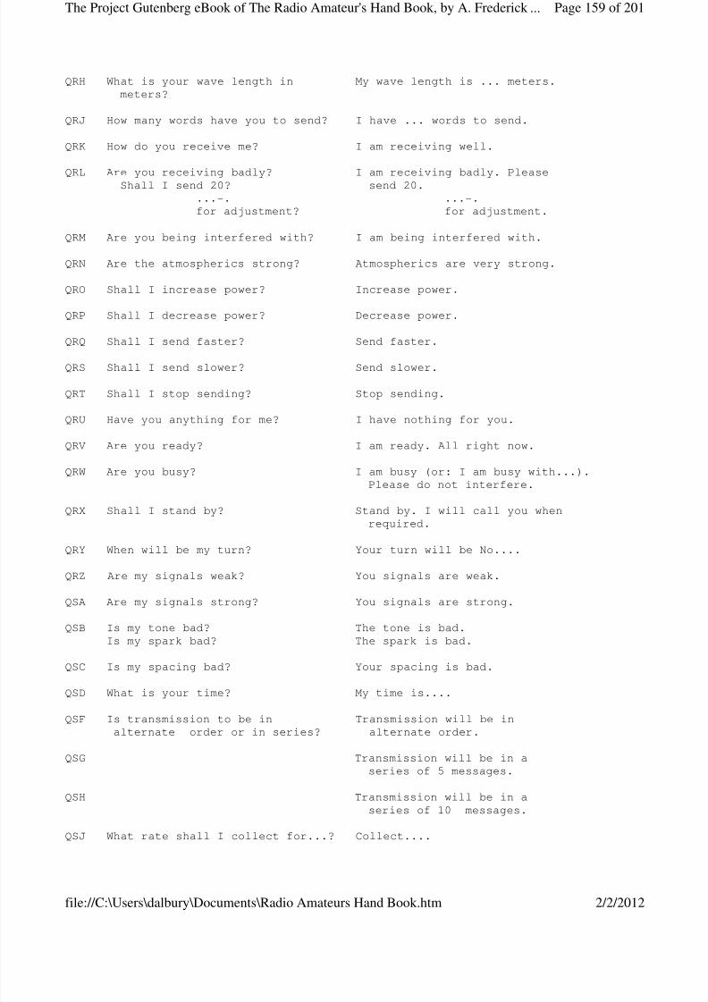
8/3/2019 Radio Amateurs Hand Book
http://slidepdf.com/reader/full/radio-amateurs-hand-book 159/201
QRH What is your wave length in My wave length is ... meters.
meters?
QRJ How many words have you to send? I have ... words to send.
QRK How do you receive me? I am receiving well.
QRL Are you receiving badly? I am receiving badly. PleaseShall I send 20? send 20....-. ...-.for adjustment? for adjustment.
QRM Are you being interfered with? I am being interfered with.
QRN Are the atmospherics strong? Atmospherics are very strong.
QRO Shall I increase power? Increase power.
QRP Shall I decrease power? Decrease power.
QRQ Shall I send faster? Send faster.
QRS Shall I send slower? Send slower.
QRT Shall I stop sending? Stop sending.
QRU Have you anything for me? I have nothing for you.
QRV Are you ready? I am ready. All right now.
QRW Are you busy? I am busy (or: I am busy with...).Please do not interfere.
QRX Shall I stand by? Stand by. I will call you when
required.
QRY When will be my turn? Your turn will be No....
QRZ Are my signals weak? You signals are weak.
QSA Are my signals strong? You signals are strong.
QSB Is my tone bad? The tone is bad.Is my spark bad? The spark is bad.
QSC Is my spacing bad? Your spacing is bad.
QSD What is your time? My time is....
QSF Is transmission to be in Transmission will be inalternate order or in series? alternate order.
QSG Transmission will be in aseries of 5 messages.
QSH Transmission will be in aseries of 10 messages.
QSJ What rate shall I collect for...? Collect....
Page 159 of 201The Project Gutenberg eBook of The Radio Amateur's Hand Book, by A. Frederick ...
2/2/2012file://C:\Users\dalbury\Documents\Radio Amateurs Hand Book.htm
8/3/2019 Radio Amateurs Hand Book
http://slidepdf.com/reader/full/radio-amateurs-hand-book 160/201
QSK Is the last radiogram canceled? The last radiogram is canceled.
QSL Did you get my receipt? Please acknowledge.
QSM What is your true course? My true course is...degrees.
QSN Are you in communication with land? I am not in communication with land.
QSO Are you in communication with I am in communication with...any ship or station (through...).(or: with...)?
QSP Shall I inform...that you are Inform...that I am calling him.calling him?
QSQ Is...calling me? You are being called by....
QSR Will you forward the radiogram? I will forward the radiogram.
QST Have you received the general General call to all stations.call?
QSU Please call me when you have Will call when I have finished.finished (or: at...o'clock)?
QSV Is public correspondence being Public correspondence is beinghandled? handled. Please do not interfere.
[Footnote: Public correspondence is any radio work, official or private, handled on commercial wavelengths.]
QSW Shall I increase my spark Increase your spark frequency.frequency?
QSX Shall I decrease my spark Decrease your spark frequency.frequency?
QSY Shall I send on a wavelength Let us change to the wave lengthof ... meters? of ... meters.
QSZ Send each word twice. I havedifficulty in receiving you.
QTA Repeat the last radiogram.
When an abbreviation is followed by a mark of interrogation, it refers to the question indicated for thatabbreviation.
Useful Information
Symbols Used For Apparatus
Page 160 of 201The Project Gutenberg eBook of The Radio Amateur's Hand Book, by A. Frederick ...
2/2/2012file://C:\Users\dalbury\Documents\Radio Amateurs Hand Book.htm
8/3/2019 Radio Amateurs Hand Book
http://slidepdf.com/reader/full/radio-amateurs-hand-book 161/201
alternatorammeteraerialarcbattery
Symbols
Page 161 of 201The Project Gutenberg eBook of The Radio Amateur's Hand Book, by A. Frederick ...
2/2/2012file://C:\Users\dalbury\Documents\Radio Amateurs Hand Book.htm
8/3/2019 Radio Amateurs Hand Book
http://slidepdf.com/reader/full/radio-amateurs-hand-book 162/201
buzzercondenservariable condenserconnection of wiresno connectioncoupled coilsvariable coupling
detectorgap, plaingap, quenchedgroundhot wire ammeterinductorvariable inductorkeyresistorvariable resistorswitch s.p.s.t.
" s.p.d.t." d.p.s.t." d.p.d.t." reversingphone receiver" transmitterthermoelementtransformervacuum tubevoltmeterchoke coil
DEFINITIONS OF ELECTRIC AND MAGNETIC UNITS
The ohm is the resistance of a thread of mercury at the temperature of melting ice, 14.4521 grams inmass, of uniform cross-section and a length of 106.300 centimeters.
The ampere is the current which when passed through a solution of nitrate of silver in water according tocertain specifications, deposits silver at the rate of 0.00111800 of a gram per second.
The volt is the electromotive force which produces a current of 1 ampere when steadily applied to aconductor the resistance of which is 1 ohm.
The coulomb is the quantity of electricity transferred by a current of 1 ampere in 1 second.
The ampere-hour is the quantity of electricity transferred by a current of 1 ampere in 1 hour and is,therefore, equal to 3600 coulombs.
The farad is the capacitance of a condenser in which a potential difference of 1 volt causes it to have acharge of 1 coulomb of electricity.
The henry is the inductance in a circuit in which the electromotive force induced is 1 volt when theinducing current varies at the rate of 1 ampere per second.
Page 162 of 201The Project Gutenberg eBook of The Radio Amateur's Hand Book, by A. Frederick ...
2/2/2012file://C:\Users\dalbury\Documents\Radio Amateurs Hand Book.htm

8/3/2019 Radio Amateurs Hand Book
http://slidepdf.com/reader/full/radio-amateurs-hand-book 163/201
The watt is the power spent by a current of 1 ampere in a resistance of 1 ohm.
The joule is the energy spent in I second by a flow of 1 ampere in 1 ohm.
The horse-power is used in rating steam machinery. It is equal to 746 watts.
The kilowatt is 1,000 watts.
The units of capacitance actually used in wireless work are the microfarad , which is the millionth part of a farad, because the farad is too large a unit; and the C. G. S. electrostatic unit of capacitance, which isoften called the centimeter of capacitance, which is about equal to 1.11 microfarads.
The units of inductance commonly used in radio work are the millihenry, which is the thousandth part of a henry; and the centimeter of inductance, which is one one-thousandth part of a microhenry.
Note.--For further information about electric and magnetic units get the Bureau of Standards Circular No. 60, called Electric Units and Standards, the price of which is 15 cents; also get Scientific Paper No.292, called International System of Electric and Magnetic Units, price 10 cents. These and other
informative papers can be had from the Superintendent of Documents, Government Printing Office,Washington, D. C.
WIRELESS BOOKS
The Admiralty Manual of Wireless Telegraphy. 1920. Published by His Majesty's Stationery Office,London.
Ralph E. Batcher.--Prepared Radio Measurements. 1921. Wireless Press, Inc., New York City.
Elmer E. Bucher.--Practical Wireless Telegraphy. 1918. Wireless Press, Inc., New York City.
Elmer E. Bucher.--Vacuum Tubes in Wireless Communication. 1919. Wireless Press, Inc., New York City.
Elmer E. Bucher.--The Wireless Experimenter's Manual. 1920. Wireless Press, Inc., New York City.
1. Frederick Collins.--Wireless Telegraphy, Its History, Theory, and Practice. 1905. McGraw Pub.Co., New York City.
2. H. Dellinger.--Principles Underlying Radio Communication.3. Signal Corps, U. S. Army, Washington, D. C.4. M. Dorsett.--Wireless Telegraphy and Telephony. 1920. Wireless Press, Ltd., London.5. A. Fleming.--Principles of Electric Wave Telegraphy. 1919. Longmans, Green and Co., London.
Charles B. Hayward.-- How to Become a Wireless Operator . 1918. American Technical Society, Chicago,Ill.
G. D. Robinson.-- Manual of Radio Telegraphy and Telephony. 1920. United States Naval Institute,Annapolis, Md.
Rupert Stanley.--Textbook of Wireless Telegraphy. 1919. Longmans, Green and Co., London.
Page 163 of 201The Project Gutenberg eBook of The Radio Amateur's Hand Book, by A. Frederick ...
2/2/2012file://C:\Users\dalbury\Documents\Radio Amateurs Hand Book.htm
8/3/2019 Radio Amateurs Hand Book
http://slidepdf.com/reader/full/radio-amateurs-hand-book 164/201
E. W. Stone.-- Elements of Radio Telegraphy. 1919. D, Van Nostrand Co., New York City.
L. B. Turner.--Wireless Telegraphy and Telephony. 1921. Cambridge University Press. Cambridge,England.
Send to the Superintendent of Documents, Government Printing Office, Washington, D. C., for a copy of Price List No. 64 which lists the Government's books and pamphlets on wireless. It will be sent to you
free of charge.
The Government publishes; (1) A List of Commercial Government and Special Wireless Stations, everyyear, price 15 cents; (2) A List of Amateur Wireless Stations, yearly, price 15 cents; (3) A WirelessService Bulletin is published monthly, price 5 cents a copy, or 25 cents yearly; and (4) WirelessCommunication Laws of the United States, the International Wireless Telegraphic Convention and Regulations Governing Wireless Operators and the Use of Wireless on Ships and Land Stations, price 15cents a copy. Orders for the above publications should be addressed to the Superintendent of Documents,Government Printing Office, Washington, D. C.
Manufacturers and Dealers in Wireless Apparatus and Supplies:
Adams-Morgan Co., Upper Montclair, N. J.
American Hard Rubber Co., 11 Mercer Street, New York City.
American Radio and Research Corporation, Medford Hillside, Mass.
Brach (L. S.) Mfg. Co., 127 Sussex Ave., Newark, N. J.
Brandes (C.) Inc., 237 Lafayette St., New York City.
Bunnell (J. H.) Company, Park Place, New York City.
Burgess Battery Company, Harris Trust Co. Bldg., Chicago, Ill.
Clapp-Eastman Co., 120 Main St., Cambridge, Mass.
Connecticut Telephone and Telegraph Co., Meriden, Conn.
Continental Fiber Co., Newark, Del.
Coto-Coil Co., Providence, R. I.
Crosley Mfg. Co., Cincinnati, Ohio.
Doolittle (F. M.), 817 Chapel St., New Haven, Conn.
Edelman (Philip E.), 9 Cortlandt St., New York City.
Edison Storage Battery Co., Orange, N. J.
Electric Specialty Co., Stamford, Conn.
Page 164 of 201The Project Gutenberg eBook of The Radio Amateur's Hand Book, by A. Frederick ...
2/2/2012file://C:\Users\dalbury\Documents\Radio Amateurs Hand Book.htm
8/3/2019 Radio Amateurs Hand Book
http://slidepdf.com/reader/full/radio-amateurs-hand-book 165/201
Electrose Mfg. Co., 60 Washington St., Brooklyn, N. Y.
General Electric Co., Schenectady, N. Y.
Grebe (A. H.) and Co., Inc., Richmond Hill, N. Y. C.
International Brass and Electric Co., 176 Beekman St., New York City.
International Insulating Co., 25 West 45th St., New York City.
King Amplitone Co., 82 Church St., New York City.
Kennedy (Colin B.) Co., Rialto Bldg., San Francisco, Cal.
Magnavox Co., Oakland, Cal.
Manhattan Electrical Supply Co., Park Place, N. Y.
Marshall-Gerken Co., Toledo, Ohio.
Michigan Paper Tube and Can Co., 2536 Grand River Ave., Detroit, Mich.
Murdock (Wm. J.) Co., Chelsea, Mass.
National Carbon Co., Inc., Long Island City, N. Y.
Pittsburgh Radio and Appliance Co., 112 Diamond St., Pittsburgh, Pa,
Radio Corporation of America, 233 Broadway, New York City.
Riley-Klotz Mfg. Co., 17-19 Mulberry St., Newark, N. J.
Radio Specialty Co., 96 Park Place, New York City.
Roller-Smith Co., 15 Barclay St., New York City.
Tuska (C. D.) Co., Hartford, Conn.
Western Electric Co., Chicago, Ill.
Westinghouse Electric Co., Pittsburgh, Pa.
Weston Electrical Instrument Co., 173 Weston Ave., Newark, N. J.
Westfield Machine Co., Westfield, Mass.
ABBREVIATIONS OF COMMON TERMS
A. ..............Aerial
A.C. ............Alternating Current
Page 165 of 201The Project Gutenberg eBook of The Radio Amateur's Hand Book, by A. Frederick ...
2/2/2012file://C:\Users\dalbury\Documents\Radio Amateurs Hand Book.htm
8/3/2019 Radio Amateurs Hand Book
http://slidepdf.com/reader/full/radio-amateurs-hand-book 166/201
A.F. ............Audio Frequency
B. and S. .......Brown & Sharpe Wire Gauge
C. ..............Capacity or Capacitance
C.G.S. ..........Centimeter-Grain-Second
Cond. ...........Condenser
Coup. ...........Coupler
C.W. ............Continuous Waves
D.C. ............Direct Current
D.P.D.T. ........Double Point Double Throw
D.P.S.T. ........Double Point Single Throw
D.X. ............Distance
E. ..............Short for Electromotive Force (Volt)
E.M.F. ..........Electromotive Force
F. ..............Filament or Frequency
G. ..............Grid
Gnd. ............Ground
I. ..............Current Strength (Ampere)
I.C.W. ..........Interrupted Continuous Waves
KW. .............Kilowatt
L. ..............Inductance
L.C. ............Loose Coupler
Litz. ...........Litzendraht
Mfd. ............Microfarad
Neg. ............Negative
O.T. ............Oscillation Transformer
P. ..............Plate
Prim. ...........Primary
Pos. ............Positive
R. ..............Resistance
R.F. ............Radio Frequency
Page 166 of 201The Project Gutenberg eBook of The Radio Amateur's Hand Book, by A. Frederick ...
2/2/2012file://C:\Users\dalbury\Documents\Radio Amateurs Hand Book.htm
8/3/2019 Radio Amateurs Hand Book
http://slidepdf.com/reader/full/radio-amateurs-hand-book 167/201
Sec. ............Secondary
S.P.D.T. ........Single Point Double Throw
S.P.S.T. ........Single Point Single Throw
S.R. ............Self Rectifying
T. ..............Telephone or Period (time) of CompleteOscillation
Tick. ...........Tickler
V. ..............Potential Difference
Var. ............Variometer
Var. Cond. ......Variable Condenser
V.T. ............Vacuum Tube
W.L. ............Wave Length
X. ..............Reactance
GLOSSARY
A BATTERY.--See Battery A.
ABBREVIATIONS, CODE.--Abbreviations of questions and answers used in wireless communication.The abbreviation of a question is usually in three letters of which the first is Q. Thus Q R B is the codeabbreviation of "what is your distance?" and the answer " My distance is..." See Page 306 [Appendix: Listof Abbreviations].
ABBREVIATIONS, UNITS.--Abbreviations of various units used in wireless electricity. Theseabbreviations are usually lower case letters of the Roman alphabet, but occasionally Greek letters areused and other signs. Thus amperes is abbreviated amp., micro, which means one millionth, [Greek: mu],etc. See Page 301 [Appendix: Useful Abbreviations].
ABBREVIATIONS OF WORDS AND TERMS.--Letters used instead of words and terms for shorteningthem up where there is a constant repetition of them, as A.C. for alternating current; C.W. for continuouswaves; V.T. for vacuum tube, etc. See Page 312 [Appendix: Abbreviations of Common Terms].
AERIAL.--Also called antenna. An aerial wire. One or more wires suspended in the air and insulated
from its supports. It is the aerial that sends out the waves and receives them.
AERIAL, AMATEUR.--An aerial suitable for sending out 200 meter wave lengths. Such an aerial wiresystem must not exceed 120 feet in length from the ground up to the aerial switch and from this throughthe leading-in wire to the end of the aerial.
AERIAL AMMETER.--See Ammeter, Hot Wire.
AERIAL, BED-SPRINGS.--Where an outdoor aerial is not practicable bed-springs are often made toserve the purpose.
Page 167 of 201The Project Gutenberg eBook of The Radio Amateur's Hand Book, by A. Frederick ...
2/2/2012file://C:\Users\dalbury\Documents\Radio Amateurs Hand Book.htm
8/3/2019 Radio Amateurs Hand Book
http://slidepdf.com/reader/full/radio-amateurs-hand-book 168/201
AERIAL CAPACITY.--See Capacity, Aerial.
AERIAL COUNTERPOISE.--Where it is not possible to get a good ground an aerial counterpoise orearth capacity can be used to advantage. The counterpoise is made like the aerial and is supporteddirectly under it close to the ground but insulated from it.
AERIAL, DIRECTIONAL.--A flat-top or other aerial that will transmit and receive over greater
distances to and from one direction than to and from another.
AERIAL, GROUND.--Signals can be received on a single long wire when it is placed on or buried in theearth or immersed in water. It is also called a ground antenna and an underground aerial.
AERIAL, LOOP.--Also called a coil aerial, coil antenna, loop aerial, loop antenna and when used forthe purpose a direction finder . A coil of wire wound on a vertical frame.
AERIAL RESISTANCE.--See Resistance, Aerial.
AERIAL SWITCH.--See Switch Aerial.
AERIAL WIRE.--(1) A wire or wires that form the aerial. (2) Wire that is used for aerials; this is usuallycopper or copper alloy.
AERIAL WIRE SYSTEM.--An aerial and ground wire and that part of the inductance coil whichconnects them. The open oscillation circuit of a sending or a receiving station.
AIR CORE TRANSFORMER.--See Transformer, Air Core.
AMATEUR AERIAL OR ANTENNA.--See Aerial, Amateur.
ALTERNATOR.--An electric machine that generates alternating current.
ALPHABET, INTERNATIONAL CODE.--A modified Morse alphabet of dots and dashes originallyused in Continental Europe and, hence, called the Continental Code. It is now used for all general publicservice wireless communication all over the world and, hence, it is called the International Code. See
age 305 [Appendix: International Morse Code].
ALTERNATING CURRENT ( A.C.)--See Current.
ALTERNATING CURRENT TRANSFORMER.--See Transformer .
AMATEUR GROUND.--See Ground, Amateur .
AMMETER.--An instrument used for measuring the current strength, in terms of amperes, that flows in acircuit. Ammeters used for measuring direct and alternating currents make use of the magnetic effects of the currents. High frequency currents make use of the heating effects of the currents.
AMMETER, HOT-WIRE.--High frequency currents are usually measured by means of an instrumentwhich depends on heating a wire or metal strip by the oscillations. Such an instrument is often called athermal ammeter , radio ammeter and aerial ammeter .
AMMETER, AERIAL.--See Ammeter, Hot Wire.
Page 168 of 201The Project Gutenberg eBook of The Radio Amateur's Hand Book, by A. Frederick ...
2/2/2012file://C:\Users\dalbury\Documents\Radio Amateurs Hand Book.htm
8/3/2019 Radio Amateurs Hand Book
http://slidepdf.com/reader/full/radio-amateurs-hand-book 169/201
AMMETER, RADIO.--See Ammeter, Hot Wire.
AMPERE.--The current which when passed through a solution of nitrate of silver in water according tocertain specifications, deposits silver at the rate of 0.00111800 of a gram per second.
AMPERE-HOUR.--The quantity of electricity transferred by a current of 1 ampere in 1 hour and is,therefore, equal to 3600 coulombs.
AMPERE-TURNS.--When a coil is wound up with a number of turns of wire and a current is made toflow through it, it behaves like a magnet. B The strength of the magnetic field inside of the coil dependson (1) the strength of the current and (2) the number of turns of wire on the coil. Thus a feeble currentflowing through a large number of turns will produce as strong a magnetic field as a strong currentflowing through a few turns of wire. This product of the current in amperes times the number of turns of wire on the coil is called the ampere-turns.
AMPLIFICATION, AUDIO FREQUENCY.--A current of audio frequency that is amplified by anamplifier tube or other means.
AMPLIFICATION, CASCADE.--See Cascade Amplification.
AMPLIFICATION, RADIO FREQUENCY.--A current of radio frequency that is amplified by anamplifier tube or other means before it reaches the detector.
AMPLIFICATION, REGENERATIVE.--A scheme that uses a third circuit to feed back part of theoscillations through a vacuum tube and which increases its sensitiveness when used as a detector andmultiplies its action as an amplifier and an oscillator.
AMPLIFIER, AUDIO FREQUENCY.--A vacuum tube or other device that amplifies the signals afterpassing through the detector.
AMPLIFIER, MAGNETIC.--A device used for controlling radio frequency currents either by means of atelegraph key or a microphone transmitter. The controlling current flows through a separate circuit fromthat of the radio current and a fraction of an ampere will control several amperes in the aerial wire.
AMPLIFIERS, MULTI-STAGE.--A receiving set using two or more amplifiers. Also called cascadeamplification.
AMPLIFIER, VACUUM TUBE.--A vacuum tube that is used either to amplify the radio frequencycurrents or the audio frequency currents.
AMPLITUDE OF WAVE.--The greatest distance that a point moves from its position of rest.
AMPLIFYING TRANSFORMER, AUDIO.--See Transformer, Audio Amplifying.
AMPLIFYING MODULATOR VACUUM TUBE.--See Vacuum Tube, Amplifying Modulator .
AMPLIFYING TRANSFORMER RADIO.--See Transformer, Radio Amplifying.
ANTENNA, AMATEUR.--See Aerial, Amateur .
ANTENNA SWITCH.--See Switch, Aerial.
Page 169 of 201The Project Gutenberg eBook of The Radio Amateur's Hand Book, by A. Frederick ...
2/2/2012file://C:\Users\dalbury\Documents\Radio Amateurs Hand Book.htm
8/3/2019 Radio Amateurs Hand Book
http://slidepdf.com/reader/full/radio-amateurs-hand-book 170/201
APPARATUS SYMBOLS.--See Symbols, Apparatus.
ARMSTRONG CIRCUIT.--See Circuit, Armstrong.
ATMOSPHERICS.--Same as Static, which see.
ATTENUATION.--In Sending wireless telegraph and telephone messages the amplitude of the electric
waves is damped out as the distance increases. This is called attenuation and it increases as the frequencyis increased. This is the reason why short wave lengths will not carry as far as long wave lengths.
AUDIO FREQUENCY AMPLIFIER.--See Amplifier, Audio Frequency.
AUDIO FREQUENCY AMPLIFICATION.--See Amplification, Audio Frequency.
AUDIBILITY METER.--See Meter, Audibility.
AUDIO FREQUENCY.--See Frequency, Audio.
AUDIO FREQUENCY CURRENT.--See Current, Audio Frequency.
AUDION.--An early trade name given to the vacuum tube detector.
AUTODYNE RECEPTOR.--See Receptor, Autodyne.
AUTO TRANSFORMER.--See Transformer, Auto.
BAKELITE.--A manufactured insulating compound.
B BATTERY.--See Battery B.
BAND, WAVE LENGTH.--See Wave Length Band .
BASKET WOUND COILS.--See Coils, Inductance.
BATTERY, A.--The 6-volt storage battery used to heat the filament of a vacuum tube, detector oramplifier.
BATTERY, B.--The 22-1/2-volt dry cell battery used to energize the plate of a vacuum tube detector oramplifier.
BATTERY, BOOSTER.--This is the battery that is connected in series with the crystal detector.
BATTERY, C.--A small dry cell battery sometimes used to give the grid of a vacuum tube detector a biaspotential.
BATTERY, EDISON STORAGE.--A storage battery in which the elements are made of nickel and ironand immersed in an alkaline electrolyte.
BATTERY, LEAD STORAGE.--A storage battery in which the elements are made of lead and immersedin an acid electrolyte.
Page 170 of 201The Project Gutenberg eBook of The Radio Amateur's Hand Book, by A. Frederick ...
2/2/2012file://C:\Users\dalbury\Documents\Radio Amateurs Hand Book.htm
8/3/2019 Radio Amateurs Hand Book
http://slidepdf.com/reader/full/radio-amateurs-hand-book 171/201
BATTERY POLES.--See Poles, Battery.
BATTERY, PRIMARY.--A battery that generates current by chemical action.
BATTERY, STORAGE.--A battery that develops a current after it has been charged.
BEAT RECEPTION.--See Heterodyne Reception.
BED SPRINGS AERIAL.--See Aerial, Bed Springs.
BLUB BLUB.--Over modulation in wireless telephony.
BROAD WAVE.--See Wave, Broad .
BRUSH DISCHARGE.--See Discharge.
BUZZER MODULATION.--See Modulation, Buzzer .
BLUE GLOW DISCHARGE.--See Discharge.
BOOSTER BATTERY.--See Battery, Booster .
BROADCASTING.--Sending out intelligence and music from a central station for the benefit of all wholive within range of it and who have receiving sets.
CAPACITANCE.--Also called by the older name of capacity. The capacity of a condenser, inductancecoil or other device capable of retaining a charge of electricity. Capacitance is measured in terms of themicrofarad .
CAPACITIVE COUPLING.--See Coupling, Capacitive.
CAPACITY.--Any object that will retain a charge of electricity; hence an aerial wire, a condenser or ametal plate is sometimes called a capacity.
CAPACITY, AERIAL.--The amount to which an aerial wire system can be charged. The capacitance of a small amateur aerial is from 0.0002 to 0.0005 microfarad.
CAPACITY, DISTRIBUTED.--A coil of wire not only has inductance, but also a certain smallcapacitance. Coils wound with their turns parallel and having a number of layers have a bunched capacitance which produces untoward effects in oscillation circuits. In honeycomb and other staggerwound coils the capacitance is more evenly distributed.
CAPACITY REACTANCE.--See Reactance, Capacity.
CAPACITY UNIT.--See Farad .
CARBON RHEOSTATS.--See Rheostat, Carbon .
CARBORUNDUM DETECTOR.--See Detector .
Page 171 of 201The Project Gutenberg eBook of The Radio Amateur's Hand Book, by A. Frederick ...
2/2/2012file://C:\Users\dalbury\Documents\Radio Amateurs Hand Book.htm

8/3/2019 Radio Amateurs Hand Book
http://slidepdf.com/reader/full/radio-amateurs-hand-book 172/201
CARRIER CURRENT TELEPHONY.--See Wired-Wireless.
CARRIER FREQUENCY.--See Frequency, Carrier .
CARRIER FREQUENCY TELEPHONY.--See Wired-Wireless.
CASCADE AMPLIFICATION.--Two or more amplifying tubes hooked up in a receiving set.
CAT WHISKER CONTACT.--A long, thin wire which makes contact with the crystal of a detector.
CENTIMETER OF CAPACITANCE.--Equal to 1.11 microfarads.
CENTIMETER OF INDUCTANCE.--Equal to one one-thousandth part of a microhenry.
CELLULAR COILS.--See Coils, Inductance.
C.G.S. ELECTROSTATIC UNIT OF CAPACITANCE.--See Centimeter of Capacitance.
CHARACTERISTICS.--The special behavior of a device, such as an aerial, a detector tube, etc.
CHARACTERISTICS, GRID.--See Grid Characteristics.
CHOKE COILS.--Coils that prevent the high voltage oscillations from surging back into the transformerand breaking down the insulation.
CHOPPER MODULATION.--See Modulation, Chopper .
CIRCUIT.--Any electrical conductor through which a current can flow. A low voltage current requires aloop of wire or other conductor both ends of which are connected to the source of current before it can
flow. A high frequency current will surge in a wire which is open at both ends like the aerial.
Closed Circuit .--A circuit that is continuous. Open Circuit .--A conductor that is not continuous. Coupled Circuits.--Open and closed circuits connected together by inductance coils, condensers or
resistances. See coupling. Close Coupled Circuits.--Open and closed circuits connected directly together with a single
inductance coil. Loose Coupled Circuits.--Opened and closed currents connected together inductively by means of a
transformer. Stand-by Circuits.--Also called pick-up circuits. When listening-in for possible calls from a number
of stations, a receiver is used which will respond to a wide band of wave lengths. Armstrong Circuits.--The regenerative circuit invented by Major E. H. Armstrong.
CLOSE COUPLED CIRCUITS.--See Currents, Close Coupled .
CLOSED CIRCUIT.--See Circuit, Closed .
CLOSED CORE TRANSFORMER.--See Transformer, Closed Core.
CODE.--
Page 172 of 201The Project Gutenberg eBook of The Radio Amateur's Hand Book, by A. Frederick ...
2/2/2012file://C:\Users\dalbury\Documents\Radio Amateurs Hand Book.htm
8/3/2019 Radio Amateurs Hand Book
http://slidepdf.com/reader/full/radio-amateurs-hand-book 173/201
Continental.--Same as International. International.--On the continent of Europe land lines use the Continental Morse alphabetic code.
This code has come to be used throughout the world for wireless telegraphy and hence it is nowcalled the International code. It is given on Page 305. [Appendix: International Morse Code].
Morse.--The code devised by Samuel F. B. Morse and which is used on the land lines in the U. S. National Electric .--A set of rules and requirements devised by the National Board of Fire
Underwriters for the electrical installations in buildings on which insurance companies carry risks.
This code also covers the requirements for wireless installations. A copy may be had from the National Board of Fire Underwriters, New York City, or from your insurance agent.
National Electric Safety.--The Bureau of Standards, Washington, D. C., have investigated theprecautions which should be taken for the safe operation of all electric equipment. A copy of the Bureau of Standards Handbook No. 3 can be had for 40 cents from the Superintendent of Documents.
COEFFICIENT OF COUPLING.--See Coupling, Coefficient of .
COIL AERIAL.--See Aerial, Loop.
COIL ANTENNA.--See Aerial, Loop.
COIL, INDUCTION.--An apparatus for changing low voltage direct currents into high voltage, lowfrequency alternating currents. When fitted with a spark gap the high voltage, low frequency currents areconverted into high voltage, high frequency currents. It is then also called a spark coil and a Ruhmkorff coil.
COIL, LOADING.--A coil connected in the aerial or closed oscillation circuit so that longer wave lengthscan be received.
COIL, REPEATING.--See Repeating Coil.
COIL, ROTATING.--One which rotates on a shaft instead of sliding as in a loose coupler . The rotor of avariometer or variocoupler is a rotating coil.
COILS, INDUCTANCE.--These are the tuning coils used for sending and receiving sets. For sending setsthey are formed of one and two coils, a single sending coil is generally called a tuning inductance coil,while a two-coil tuner is called an oscillation transformer . Receiving tuning coils are made with a singlelayer, single coil, or a pair of coils, when it is called an oscillation transformer . Some tuning inductancecoils have more than one layer, they are then called lattice wound , cellular , basket wound , honeycomb,duo-lateral, stagger wound , spider-web and slab coils.
COMMERCIAL FREQUENCY.--See Frequency, Commercial.
CONDENSER, AERIAL SERIES.--A condenser placed in the aerial wire system to cut down the wavelength.
CONDENSER, VERNIER.--A small variable condenser used for receiving continuous waves where verysharp tuning is desired.
CONDENSER.--All conducting objects with their insulation form capacities, but a condenser isunderstood to mean two sheets or plates of metal placed closely together but separated by some insulatingmaterial.
Page 173 of 201The Project Gutenberg eBook of The Radio Amateur's Hand Book, by A. Frederick ...
2/2/2012file://C:\Users\dalbury\Documents\Radio Amateurs Hand Book.htm
8/3/2019 Radio Amateurs Hand Book
http://slidepdf.com/reader/full/radio-amateurs-hand-book 174/201
Adjustable Condenser .--Where two or more condensers can be coupled together by means of plugs,switches or other devices.
Aerial Condenser .--A condenser connected in the aerial. Air Condenser .--Where air only separates the sheets of metal. By-Pass Condenser .--A condenser connected in the transmitting currents so that the high frequency
currents cannot flow back through the power circuit. Filter Condenser .--A condenser of large capacitance used in combination with a filter reactor for
smoothing out the pulsating direct currents as they come from the rectifier. Fixed Condenser .--Where the plates are fixed relatively to one another. Grid Condenser .--A condenser connected in series with the grid lead. Leyden Jar Condenser .--Where glass jars are used. Mica Condenser .--Where mica is used. Oil Condenser .--Where the plates are immersed in oil. Paper Condenser .--Where paper is used as the insulating material. Protective.--A condenser of large capacity connected across the low voltage supply circuit of a
transmitter to form a by-path of kick-back oscillations. Variable Condenser .--Where alternate plates can be moved and so made to interleave more or less
with a set of fixed plates.
Vernier .--A small condenser with a vernier on it so that it can be very accurately varied. It isconnected in parallel with the variable condenser used in the primary circuit and is used for thereception of continuous waves where sharp tuning is essential.
CONDENSITE.--A manufactured insulating compound.
CONDUCTIVITY.--The conductance of a given length of wire of uniform cross section. The reciprocalof resistivity.
CONTACT DETECTORS.--See Detectors, Contact .
CONTINENTAL CODE.--See Code, Continental.
COULOMB.--The quantity of electricity transferred by a current of 1 ampere in 1 second.
CONVECTIVE DISCHARGE.--See Discharge.
CONVENTIONAL SIGNALS.--See Signals, Conventional.
COUNTER ELECTROMOTIVE FORCE.--See Electromotive Force, Counter .
COUNTERPOISE. A duplicate of the aerial wire that is raised a few feet above the earth and insulatedfrom it. Usually no connection is made with the earth itself.
COUPLED CIRCUITS.--See Circuit, Coupled .
COUPLING.--When two oscillation circuits are connected together either by the magnetic field of aninductance coil, or by the electrostatic field of a condenser.
COUPLING, CAPACITIVE.--Oscillation circuits when connected together by condensers instead of inductance coils.
COUPLING, COEFFICIENT OF.--The measure of the closeness of the coupling between two coils.
Page 174 of 201The Project Gutenberg eBook of The Radio Amateur's Hand Book, by A. Frederick ...
2/2/2012file://C:\Users\dalbury\Documents\Radio Amateurs Hand Book.htm
8/3/2019 Radio Amateurs Hand Book
http://slidepdf.com/reader/full/radio-amateurs-hand-book 175/201
COUPLING, INDUCTIVE.--Oscillation circuits when connected together by inductance coils.
COUPLING, RESISTANCE.--Oscillation circuits connected together by a resistance.
CRYSTAL RECTIFIER.--A crystal detector.
CURRENT, ALTERNATING ( A.C.).--A low frequency current that surges to and fro in a circuit.
CURRENT, AUDIO FREQUENCY.--A current whose frequency is low enough to be heard in atelephone receiver. Such a current usually has a frequency of between 200 and 2,000 cycles per second.
CURRENT, PLATE.--The current which flows between the filament and the plate of a vacuum tube.
CURRENT, PULSATING.--A direct current whose voltage varies from moment to moment.
CURRENT, RADIO FREQUENCY.--A current whose frequency is so high it cannot be heard in atelephone receiver. Such a current may have a frequency of from 20,000 to 10,000,000 per second.
CURRENTS, HIGH FREQUENCY.--(1) Currents that oscillate from 10,000 to 300,000,000 times persecond. (2) Electric oscillations.
CURRENTS, HIGH POTENTIAL.--(1) Currents that have a potential of more than 10,000 volts. (2)High voltage currents.
CYCLE.--(1) A series of changes which when completed are again at the starting point. (2) A period of time at the end of which an alternating or oscillating current repeats its original direction of flow.
DAMPING.--The degree to which the energy of an electric oscillation is reduced. In an open circuit theenergy of an oscillation set up by a spark gap is damped out in a few swings, while in a closed circuit it is
greatly prolonged, the current oscillating 20 times or more before the energy is dissipated by the sum of the resistances of the circuit.
DECREMENT.--The act or process of gradually becoming less.
DETECTOR.--Any device that will (1) change the oscillations set up by the incoming waves into directcurrent, that is which will rectify them, or (2) that will act as a relay.
Carborundum.--One that uses a carborundum crystal for the sensitive element. Carborundum is acrystalline silicon carbide formed in the electric furnace.
Cat Whisker Contact .--See Cat Whisker Contact . Chalcopyrite.--Copper pyrites. A brass colored mineral used as a crystal for detectors. See Zincite. Contact .--A crystal detector. Any kind of a detector in which two dissimilar but suitable solids
make contact. Ferron.--A detector in which iron pyrites are used as the sensitive element. Galena.--A detector that uses a galena crystal for the rectifying element. Iron Pyrites.--A detector that uses a crystal of iron pyrites for its sensitive element. Molybdenite.--A detector that uses a crystal of sulphide of molybdenum for the sensitive element. Perikon.--A detector in which a bornite crystal makes contact with a zincite crystal. Silicon.--A detector that uses a crystal of silicon for its sensitive element. Vacuum Tube.--A vacuum tube (which see) used as a detector. Zincite.--A detector in which a crystal of zincite is used as the sensitive element.
Page 175 of 201The Project Gutenberg eBook of The Radio Amateur's Hand Book, by A. Frederick ...
2/2/2012file://C:\Users\dalbury\Documents\Radio Amateurs Hand Book.htm
8/3/2019 Radio Amateurs Hand Book
http://slidepdf.com/reader/full/radio-amateurs-hand-book 176/201
DE TUNING.--A method of signaling by sustained oscillations in which the key when pressed down cutsout either some of the inductance or some of the capacity and hence greatly changes the wave length.
DIELECTRIC.--An insulating material between two electrically charged plates in which there is set up anelectric strain, or displacement.
DIELECTRIC STRAIN.--The electric displacement in a dielectric.
DIRECTIONAL AERIAL.--See Aerial, Directional.
DIRECTION FINDER.--See Aerial, Loop.
DISCHARGE.--(1) A faintly luminous discharge that takes place from the positive pointed terminal of aninduction coil, or other high potential apparatus; is termed a brush discharge. (2) A continuous dischargebetween the terminals of a high potential apparatus is termed a convective discharge. (3) The suddenbreaking-down of the air between the balls forming the spark gap is termed a disruptive discharge; alsocalled an electric spark , or just spark for short. (4) When a tube has a poor vacuum, or too large a batteryvoltage, it glows with a blue light and this is called a blue glow discharge.
DISRUPTIVE DISCHARGE.--See Discharge.
DISTRESS CALL. [Morse code:] ...---... (SOS).
DISTRIBUTED CAPACITY.--See Capacity, Distributed .
DOUBLE HUMP RESONANCE CURVE.--A resonance curve that has two peaks or humps which showthat the oscillating currents which are set up when the primary and secondary of a tuning coil are closelycoupled have two frequencies.
DUO-LATERAL COILS.--See Coils, Inductance.
DUPLEX COMMUNICATION.--A wireless telephone system with which it is possible to talk betweenboth stations in either direction without the use of switches. This is known as the duplex system.
EARTH CAPACITY.--An aerial counterpoise.
EARTH CONNECTION.--Metal plates or wires buried in the ground or immersed in water. Any kind of means by which the sending and receiving apparatus can be connected with the earth.
EDISON STORAGE BATTERY.--See Storage Battery, Edison.
ELECTRIC ENERGY.--The power of an electric current.
ELECTRIC OSCILLATIONS.--See Oscillations, Electric.
ELECTRIC SPARK.--See Discharge, Spark .
ELECTRICITY, NEGATIVE.--The opposite of positive electricity. Negative electricity is formed of negative electrons which make up the outside particles of an atom.
Page 176 of 201The Project Gutenberg eBook of The Radio Amateur's Hand Book, by A. Frederick ...
2/2/2012file://C:\Users\dalbury\Documents\Radio Amateurs Hand Book.htm
8/3/2019 Radio Amateurs Hand Book
http://slidepdf.com/reader/full/radio-amateurs-hand-book 177/201
ELECTRICITY, POSITIVE.--The opposite of negative electricity. Positive electricity is formed of positive electrons which make up the inside particles of an atom.
ELECTRODES.--Usually the parts of an apparatus which dip into a liquid and carry a current. Theelectrodes of a dry battery are the zinc and carbon elements. The electrodes of an Edison storage batteryare the iron and nickel elements, and the electrodes of a lead storage battery are the lead elements.
ELECTROLYTES.--The acid or alkaline solutions used in batteries.
ELECTROMAGNETIC WAVES.--See Waves, Electric.
ELECTROMOTIVE FORCE.--Abbreviated emf . The force that drives an electric current along aconductor. Also loosely called voltage.
ELECTROMOTIVE FORCE, COUNTER.--The emf. that is set up in a direction opposite to that inwhich the current is flowing in a conductor.
ELECTRON.--(1) A negative particle of electricity that is detached from an atom. (2) A negative particle
of electricity thrown off from the incandescent filament of a vacuum tube.
ELECTRON FLOW.--The passage of electrons between the incandescent filament and the coldpositively charged plate of a vacuum tube.
ELECTRON RELAY.--See Relay, Electron.
ELECTRON TUBE.--A vacuum tube or a gas-content tube used for any purpose in wireless work. SeeVacuum Tube.
ELECTROSE INSULATORS.--Insulators made of a composition material the trade name of which is
Electrose.
ENERGY, ELECTRIC.--See Electric Energy.
ENERGY UNIT.--The joule, which see, Page 308 [Appendix: Definitions of Electric and MagneticUnits].
FADING.--The sudden variation in strength of signals received from a transmitting station when all theadjustments of both sending and receiving apparatus remain the same. Also called swinging.
FARAD.--The capacitance of a condenser in which a potential difference of 1 volt causes it to have acharge of 1 coulomb of electricity.
FEED-BACK ACTION.--Feeding back the oscillating currents in a vacuum tube to amplify its power.Also called regenerative action.
FERROMAGNETIC CONTROL.--See Magnetic Amplifier .
FILAMENT.--The wire in a vacuum tube that is heated to incandescence and which throws off electrons.
FILAMENT RHEOSTAT.--See Rheostat, Filament .
Page 177 of 201The Project Gutenberg eBook of The Radio Amateur's Hand Book, by A. Frederick ...
2/2/2012file://C:\Users\dalbury\Documents\Radio Amateurs Hand Book.htm

8/3/2019 Radio Amateurs Hand Book
http://slidepdf.com/reader/full/radio-amateurs-hand-book 178/201
FILTER.--Inductance coils or condensers or both which (1) prevent troublesome voltages from acting onthe different circuits, and (2) smooth out alternating currents after they have been rectified.
FILTER REACTOR.--See Reactor, Filter .
FIRE UNDERWRITERS.--See Code, National Electric.
FIXED GAP.--See Gap.
FLEMING VALVE.--A two-electrode vacuum tube.
FORCED OSCILLATIONS.--See Oscillations, Forced .
FREE OSCILLATIONS.--See Oscillations, Free.
FREQUENCY, AUDIO.--(1) An alternating current whose frequency is low enough to operate atelephone receiver and, hence, which can be heard by the ear. (2) Audio frequencies are usually around500 or 1,000 cycles per second, but may be as low as 200 and as high as 10,000 cycles per second.
Carrier .--A radio frequency wave modulated by an audio frequency wave which results in settingof three radio frequency waves. The principal radio frequency is called the carrier frequency, sinceit carries or transmits the audio frequency wave.
Commercial.--(1) Alternating current that is used for commercial purposes, namely, light, heat andpower. (2) Commercial frequencies now in general use are from 25 to 50 cycles per second.
Natural.--The pendulum and vibrating spring have a natural frequency which depends on the size,material of which it is made, and the friction which it has to overcome. Likewise an oscillationcircuit has a natural frequency which depends upon its inductance, capacitance and resistance.
Radio.--(1) An oscillating current whose frequency is too high to affect a telephone receiver and,hence, cannot be heard by the ear. (2) Radio frequencies are usually between 20,000 and 2,000,000cycles per second but may be as low as 10,000 and as high as 300,000,000 cycles per second.
Spark.--The number of sparks per second produced by the discharge of a condenser.
GAP, FIXED.--One with fixed electrodes.
GAP, NON-SYNCHRONOUS.--A rotary spark gap run by a separate motor which may be widelydifferent from that of the speed of the alternator.
GAP, QUENCHED.--(1) A spark gap for the impulse production of oscillating currents. (2) This methodcan be likened to one where a spring is struck a single sharp blow and then continues to set up vibrations.
GAP, ROTARY.--One having fixed and rotating electrodes.
GAP, SYNCHRONOUS.--A rotary spark gap run at the same speed as the alternator which supplies thepower transformer. Such a gap usually has as many teeth as there are poles on the generator. Hence onespark occurs per half cycle.
GAS-CONTENT TUBE.--See Vacuum Tube.
GENERATOR TUBE.--A vacuum tube used to set up oscillations. As a matter of fact it does notgenerate oscillations, but changes the initial low voltage current that flows through it into oscillations.Also called an oscillator tube and a power tube.
Page 178 of 201The Project Gutenberg eBook of The Radio Amateur's Hand Book, by A. Frederick ...
2/2/2012file://C:\Users\dalbury\Documents\Radio Amateurs Hand Book.htm

8/3/2019 Radio Amateurs Hand Book
http://slidepdf.com/reader/full/radio-amateurs-hand-book 179/201
GRID BATTERY.--See Battery C.
GRID CHARACTERISTICS.--The various relations that could exist between the voltages and currents of the grid of a vacuum tube, and the values which do exist between them when the tube is in operation.These characteristics are generally shown by curves.
GRID CONDENSER.--See Condenser, Grid.
GRID LEAK.--A high resistance unit connected in the grid lead of both sending and receiving sets. In asending set it keeps the voltage of the grid at a constant value and so controls the output of the aerial. In areceiving set it controls the current flowing between the plate and filament.
GRID MODULATION.--See Modulation, Grid.
GRID POTENTIAL.--The negative or positive voltage of the grid of a vacuum tube.
GRID VOLTAGE.--See Grid Potential.
GRINDERS.--The most common form of Static, which see. They make a grinding noise in theheadphones.
GROUND.--See Earth Connection.
GROUND, AMATEUR.--A water-pipe ground.
GROUND, WATERPIPE.--A common method of grounding by amateurs is to use the waterpipe, gaspipeor radiator.
GUIDED WAVE TELEPHONY.--See Wired Wireless.
HARD TUBE.--A vacuum tube in which the vacuum is high, that is, exhausted to a high degree.
HELIX.--(1) Any coil of wire. (2) Specifically a transmitter tuning inductance coil.
HENRY.--The inductance in a circuit in which the electromotive force induced is 1 volt when theinducing current varies at the rate of 1 ampere per second.
HETERODYNE RECEPTION.--(1) Receiving by the beat method. (2) Receiving by means of superposing oscillations generated at the receiving station on the oscillations set up in the aerial by theincoming waves.
HETERODYNE RECEPTOR.--See Receptor, Heterodyne.
HIGH FREQUENCY CURRENTS.--See Currents, High Frequency.
HIGH FREQUENCY RESISTANCE.--See Resistance, High Frequency.
HIGH POTENTIAL CURRENTS.--See Currents, High Potential.
HIGH VOLTAGE CURRENTS.--See Currents, High Potential.
Page 179 of 201The Project Gutenberg eBook of The Radio Amateur's Hand Book, by A. Frederick ...
2/2/2012file://C:\Users\dalbury\Documents\Radio Amateurs Hand Book.htm
8/3/2019 Radio Amateurs Hand Book
http://slidepdf.com/reader/full/radio-amateurs-hand-book 180/201
HONEYCOMB COILS.--See Coils, Inductance.
HORSE-POWER.--Used in rating steam machinery. It is equal to 746 watts.
HOT WIRE AMMETER.--See Ammeter, Hot Wire.
HOWLING.--Where more than three stages of radio amplification, or more than two stages of audio
amplification, are used howling noises are apt to occur in the telephone receivers.
IMPEDANCE.--An oscillation circuit has reactance and also resistance, and when these are combinedthe total opposition to the current is called impedance.
INDUCTANCE COILS.--See Coils, Inductance.
INDUCTANCE COIL, LOADING.--See Coil, Loading Inductance.
INDUCTIVE COUPLING.--See Coupling, Inductive.
INDUCTIVE REACTANCE.--See Reactance, Inductive.
INDUCTION COIL.--See Coil, Induction.
INDUCTION, MUTUAL.--Induction produced between two circuits or coils close to each other by themutual interaction of their magnetic fields.
INSULATION.--Materials used on and around wires and other conductors to keep the current fromleaking away.
INSPECTOR, RADIO.--A U. S. inspector whose business it is to issue both station and operators'
licenses in the district of which he is in charge.
INTERFERENCE.--The crossing or superposing of two sets of electric waves of the same or slightlydifferent lengths which tend to oppose each other. It is the untoward interference between electric wavesfrom different stations that makes selective signaling so difficult a problem.
INTERMEDIATE WAVES.--See Waves.
IONIC TUBES.--See Vacuum Tubes.
INTERNATIONAL CODE.--See Code, International.
JAMMING.--Waves that are of such length and strength that when they interfere with incoming wavesthey drown them out.
JOULE.--The energy spent in 1 second by a flow of 1 ampere in 1 ohm.
JOULE'S LAW.--The relation between the heat produced in seconds to the resistance of the circuit, to thecurrent flowing in it.
KENOTRON.--The trade name of a vacuum tube rectifier made by the Radio Corporation of America.
Page 180 of 201The Project Gutenberg eBook of The Radio Amateur's Hand Book, by A. Frederick ...
2/2/2012file://C:\Users\dalbury\Documents\Radio Amateurs Hand Book.htm
8/3/2019 Radio Amateurs Hand Book
http://slidepdf.com/reader/full/radio-amateurs-hand-book 181/201
KICK-BACK.--Oscillating currents that rise in voltage and tend to flow back through the circuit that issupplying the transmitter with low voltage current.
KICK-BACK PREVENTION.--See Prevention, Kick-Back.
KILOWATT.--1,000 watts.
LAMBDA.--See Pages 301, 302. [Appendix: Useful Abbreviations].
LATTICE WOUND COILS.--See Coils, Inductance.
LIGHTNING SWITCH.--See Switch, Lightning.
LINE RADIO COMMUNICATION.--See Wired Wireless.
LINE RADIO TELEPHONY.--See Telephony, Line Radio.
LITZENDRAHT.--A conductor formed of a number of fine copper wires either twisted or braided
together. It is used to reduce the skin effect. See Resistance, High Frequency.
LOAD FLICKER.--The flickering of electric lights on lines that supply wireless transmitting sets due tovariations of the voltage on opening and closing the key.
LOADING COIL.--See Coil, Loading.
LONG WAVES.--See Waves.
LOOP AERIAL.--See Aerial, Loop.
LOOSE COUPLED CIRCUITS.--See Circuits, Loose Coupled.
LOUD SPEAKER.--A telephone receiver connected to a horn, or a specially made one, that reproducesthe incoming signals, words or music loud enough to be heard by a room or an auditorium full of people,or by large crowds out-doors.
MAGNETIC POLES.--See Poles, Magnetic.
MEGOHM.--One million ohms.
METER, AUDIBILITY.--An instrument for measuring the loudness of a signal by comparison withanother signal. It consists of a pair of headphones and a variable resistance which have been calibrated.
MHO.--The unit of conductance. As conductance is the reciprocal of resistance it is measured by thereciprocal ohm or mho.
MICA.--A transparent mineral having a high insulating value and which can be split into very thin sheets.It is largely used in making condensers both for transmitting and receiving sets.
MICROFARAD.--The millionth part of a farad.
Page 181 of 201The Project Gutenberg eBook of The Radio Amateur's Hand Book, by A. Frederick ...
2/2/2012file://C:\Users\dalbury\Documents\Radio Amateurs Hand Book.htm
8/3/2019 Radio Amateurs Hand Book
http://slidepdf.com/reader/full/radio-amateurs-hand-book 182/201
MICROHENRY.--The millionth part of a farad.
MICROMICROFARAD.--The millionth part of a microfarad.
MICROHM.--The millionth part of an ohm.
MICROPHONE TRANSFORMER.--See Transformer, Microphone.
MICROPHONE TRANSMITTER.--See Transmitter, Microphone.
MILLI-AMMETER.--An ammeter that measures a current by the one-thousandth of an ampere.
MODULATION.--(1) Inflection or varying the voice. (2) Varying the amplitude of oscillations by meansof the voice.
MODULATION, BUZZER.--The modulation of radio frequency oscillations by a buzzer which breaksup the sustained oscillations of a transmitter into audio frequency impulses.
MILLIHENRY.--The thousandth part of a henry.
MODULATION, CHOPPER.--The modulation of radio frequency oscillations by a chopper whichbreaks up the sustained oscillations of a transmitter into audio frequency impulses.
MODULATION, GRID.--The scheme of modulating an oscillator tube by connecting the secondary of atransformer, the primary of which is connected with a battery and a microphone transmitter, in the gridlead.
MODULATION, OVER.--See Blub Blub.
MODULATION, PLATE.--Modulating the oscillations set up by a vacuum tube by varying the currentimpressed on the plate.
MODULATOR TUBE.--A vacuum tube used as a modulator.
MOTION, WAVE.--(1) The to and fro motion of water at sea. (2) Waves transmitted by, in and throughthe air, or sound waves. (3) Waves transmitted by, in and through the ether, or electromagnetic waves, orelectric waves for short.
MOTOR-GENERATOR.--A motor and a dynamo built to run at the same speed and mounted on acommon base, the shafts being coupled together. In wireless it is used for changing commercial directcurrent into direct current of higher voltages for energizing the plate of a vacuum tube oscillator.
MULTI-STAGE AMPLIFIERS.--See Amplifiers, Multi-Stage.
MUTUAL INDUCTION.--See Induction, Mutual.
MUSH.--Irregular intermediate frequencies set up by arc transmitters which interfere with thefundamental wave lengths.
MUSHY NOTE.--A note that is not clear cut, and hence hard to read, which is received by the
Page 182 of 201The Project Gutenberg eBook of The Radio Amateur's Hand Book, by A. Frederick ...
2/2/2012file://C:\Users\dalbury\Documents\Radio Amateurs Hand Book.htm
8/3/2019 Radio Amateurs Hand Book
http://slidepdf.com/reader/full/radio-amateurs-hand-book 183/201
heterodyne method when damped waves or modulated continuous waves are being received.
NATIONAL ELECTRIC CODE.--See Code, National Electric.
NATIONAL ELECTRIC SAFETY CODE.--See Code, National Electric Safety.
NEGATIVE ELECTRICITY.--See Electricity, Negative.
NON-SYNCHRONOUS GAP.--See Gap, Non-Synchronous.
OHM.--The resistance of a thread of mercury at the temperature of melting ice, 14.4521 grams in mass,of uniform cross-section and a length of 106.300 centimeters.
OHM'S LAW.--The important fixed relation between the electric current, its electromotive force and theresistance of the conductor in which it flows.
OPEN CIRCUIT.--See Circuit, Open.
OPEN CORE TRANSFORMER.--See Transformer, Open Core.
OSCILLATION TRANSFORMER.--See Transformer, Oscillation.
OSCILLATIONS, ELECTRIC.--A current of high frequency that surges through an open or a closedcircuit. (1) Electric oscillations may be set up by a spark gap, electric arc or a vacuum tube, when theyhave not only a high frequency but a high potential, or voltage. (2) When electric waves impinge on anaerial wire they are transformed into electric oscillations of a frequency equal to those which emitted thewaves, but since a very small amount of energy is received their potential or voltage is likewise verysmall.
Sustained.--Oscillations in which the damping factor is small. Damped.--Oscillations in which the damping factor is large. Free.--When a condenser discharges through an oscillation circuit, where there is no outside
electromotive force acting on it, the oscillations are said to be free. Forced.--Oscillations that are made to surge in a circuit whose natural period is different from that
of the oscillations set up in it.
OSCILLATION TRANSFORMER.--See Transformer.
OSCILLATION VALVE.--See Vacuum Tube.
OSCILLATOR TUBE.--A vacuum tube which is used to produce electric oscillations.
OVER MODULATION.--See Blub Blub.
PANCAKE OSCILLATION TRANSFORMER.--Disk-shaped coils that are used for receiving tuninginductances.
PERMEABILITY, MAGNETIC.--The degree to which a substance can be magnetized. Iron has a greatermagnetic permeability than air.
PHASE.--A characteristic aspect or appearance that takes place at the same point or part of a cycle.
Page 183 of 201The Project Gutenberg eBook of The Radio Amateur's Hand Book, by A. Frederick ...
2/2/2012file://C:\Users\dalbury\Documents\Radio Amateurs Hand Book.htm

8/3/2019 Radio Amateurs Hand Book
http://slidepdf.com/reader/full/radio-amateurs-hand-book 184/201
PICK-UP CIRCUITS.--See Circuits, Stand-by.
PLATE CIRCUIT REACTOR.--See Reactor, Plate Circuit.
PLATE CURRENT.--See Current, Plate.
PLATE MODULATION.--See Modulation, Plate.
PLATE VOLTAGE.--See Foliage, Plate.
POLES, BATTERY.--The positive and negative terminals of the elements of a battery. On a storagebattery these poles are marked + and - respectively.
POLES, MAGNETIC.--The ends of a magnet.
POSITIVE ELECTRICITY.--See Electricity, Positive.
POTENTIAL DIFFERENCE.--The electric pressure between two charged conductors or surfaces.
POTENTIOMETER.--A variable resistance used for subdividing the voltage of a current. A voltagedivider.
POWER TRANSFORMER.--See Transformer, Power.
POWER TUBE.--See Generator Tube.
PRIMARY BATTERY.--See Battery, Primary.
PREVENTION, KICK-BACK.--A choke coil placed in the power circuit to prevent the high frequency
currents from getting into the transformer and breaking down the insulation.
Q S T.--An abbreviation used in wireless communication for (1) the question "Have you received thegeneral call?" and (2) the notice, "General call to all stations."
QUENCHED GAP.--See Gap, Quenched.
RADIATION.--The emission, or throwing off, of electric waves by an aerial wire system.
RADIO AMMETER.--See Ammeter, Hot Wire.
RADIO FREQUENCY.--See Frequency, Radio.
RADIO FREQUENCY AMPLIFICATION.--See Amplification, Radio Frequency.
RADIO FREQUENCY CURRENT.--See Current, Radio Frequency.
RADIO INSPECTOR.--See Inspector, Radio.
RADIOTRON.--The trade name of vacuum tube detectors, amplifiers, oscillators and modulators madeby the Radio Corporation of America.
Page 184 of 201The Project Gutenberg eBook of The Radio Amateur's Hand Book, by A. Frederick ...
2/2/2012file://C:\Users\dalbury\Documents\Radio Amateurs Hand Book.htm
8/3/2019 Radio Amateurs Hand Book
http://slidepdf.com/reader/full/radio-amateurs-hand-book 185/201
RADIO WAVES.--See Waves, Radio.
REACTANCE.--When a circuit has inductance and the current changes in value, it is opposed by thevoltage induced by the variation of the current.
REACTANCE, CAPACITY.--The capacity reactance is the opposition offered to a current by a capacity.It is measured as a resistance, that is, in ohms.
RECEIVING TUNING COILS.--See Coils, Inductance.
RECEIVER, LOUD SPEAKING.--See Loud Speakers.
RECEIVER, WATCH CASE.--A compact telephone receiver used for wireless reception.
REACTANCE, INDUCTIVE.--The inductive reactance is the opposition offered to the current by aninductance coil. It is measured as a resistance, that is, in ohms.
REACTOR, FILTER.--A reactance coil for smoothing out the pulsating direct currents as they come
from the rectifier.
REACTOR, PLATE CIRCUIT.--A reactance coil used in the plate circuit of a wireless telephone to keepthe direct current supply at a constant voltage.
RECEIVER.--(1) A telephone receiver. (2) An apparatus for receiving signals, speech or music. (3)Better called a receptor to distinguish it from a telephone receiver.
RECTIFIER.--(1) An apparatus for changing alternating current into pulsating direct current. (2)Specifically in wireless (a) a crystal or vacuum tube detector, and (b) a two-electrode vacuum tube usedfor changing commercial alternating current into direct current for wireless telephony.
REGENERATIVE AMPLIFICATION.--See Amplification, Regenerative .
RECEPTOR.--A receiving set.
RECEPTOR, AUTODYNE.--A receptor that has a regenerative circuit and the same tube is used as adetector and as a generator of local oscillations.
RECEPTOR, BEAT.--A heterodyne receptor.
RECEPTOR, HETERODYNE.--A receiving set that uses a separate vacuum tube to set up the secondseries of waves for beat reception.
REGENERATIVE ACTION.--See Feed-Back Action.
REGENERATIVE AMPLIFICATION.--See Amplification, Regenerative.
RELAY, ELECTRON.--A vacuum tube when used as a detector or an amplifier.
REPEATING COIL.--A transformer used in connecting up a wireless receiver with a wire transmitter.
Page 185 of 201The Project Gutenberg eBook of The Radio Amateur's Hand Book, by A. Frederick ...
2/2/2012file://C:\Users\dalbury\Documents\Radio Amateurs Hand Book.htm

8/3/2019 Radio Amateurs Hand Book
http://slidepdf.com/reader/full/radio-amateurs-hand-book 186/201
RESISTANCE.--The opposition offered by a wire or other conductor to the passage of a current.
RESISTANCE, AERIAL.--The resistance of the aerial wire to oscillating currents. This is greater than itsordinary ohmic resistance due to the skin effect. See Resistance, High Frequency.
RESISTANCE BOX.--See Resistor.
RESISTANCE COUPLING.--See Coupling, Resistance.
RESISTANCE, HIGH FREQUENCY.--When a high frequency current oscillates on a wire two thingstake place that are different than when a direct or alternating current flows through it, and these are (1)the current inside of the wire lags behind that of the current on the surface, and (2) the amplitude of thecurrent is largest on the surface and grows smaller as the center of the wire is reached. This unevendistribution of the current is known as the skin effect and it amounts to the same thing as reducing the sizeof the wire, hence the resistance is increased.
RESISTIVITY.--The resistance of a given length of wire of uniform cross section. The reciprocal of conductivity.
RESISTOR.--A fixed or variable resistance unit or a group of such units. Variable resistors are alsocalled resistance boxes and more often rheostats.
RESONANCE.--(1) Simple resonance of sound is its increase set up by one body by the sympatheticvibration of a second body. (2) By extension the increase in the amplitude of electric oscillations whenthe circuit in which they surge has a natural period that is the same, or nearly the same, as the period of the first oscillation circuit.
RHEOSTAT.--A variable resistance unit. See Resistor.
RHEOSTAT, CARBON.--A carbon rod, or carbon plates or blocks, when used as variable resistances.
RHEOSTAT, FILAMENT.--A variable resistance used for keeping the current of the storage batterywhich heats the filament of a vacuum tube at a constant voltage.
ROTATING COIL.--See Coil.
ROTARY GAP.--See Gap.
ROTOR.--The rotating coil of a variometer or a variocoupler.
RUHMKORFF COIL.--See Coil, Induction.
SATURATION.--The maximum plate current that a vacuum tube will take.
SENSITIVE SPOTS.--Spots on detector crystals that are sensitive to the action of electric oscillations.
SHORT WAVES.--See Waves.
SIDE WAVES.--See Wave Length Band.
Page 186 of 201The Project Gutenberg eBook of The Radio Amateur's Hand Book, by A. Frederick ...
2/2/2012file://C:\Users\dalbury\Documents\Radio Amateurs Hand Book.htm
8/3/2019 Radio Amateurs Hand Book
http://slidepdf.com/reader/full/radio-amateurs-hand-book 187/201
SIGNALS, CONVENTIONAL.--(1) The International Morse alphabet and numeral code, punctuationmarks, and a few important abbreviations used in wireless telegraphy. (2) Dot and dash signals fordistress call, invitation to transmit, etc. Now used for all general public service wireless communication.
SKIN EFFECT.--See Resistance, High Frequency.
SOFT TUBE.--A vacuum tube in which the vacuum is low, that is, it is not highly exhausted.
SPACE CHARGE EFFECT.--The electric field intensity due to the pressure of the negative electrons inthe space between the filament and plate which at last equals and neutralizes that due to the positivepotential of the plate so that there is no force acting on the electrons near the filament.
SPARK.--See Discharge.
SPARK COIL.--See Coil, Induction.
SPARK DISCHARGE.--See Spark, Electric.
SPARK FREQUENCY.--See Frequency, Spark.
SPARK GAP.--(1) A spark gap, without the hyphen, means the apparatus in which sparks take place; it isalso called a spark discharger. (2) Spark-gap, with the hyphen, means the air-gap between the opposedfaces of the electrodes in which sparks are produced.
Plain.--A spark gap with fixed electrodes. Rotary.--A spark gap with a pair of fixed electrodes and a number of electrodes mounted on a
rotating element. Quenched.--A spark gap formed of a number of metal plates placed closely together and insulated
from each other.
SPIDER WEB INDUCTANCE COIL.--See Coil, Spider Web Inductance.
SPREADER.--A stick of wood, or spar, that holds the wires of the aerial apart.
STAGGER WOUND COILS.--See Coils, Inductance.
STAND-BY CIRCUITS.--See Circuits, Stand-By.
STATIC.--Also called atmospherics, grinders, strays, X's, and, when bad enough, by other names. It is anelectrical disturbance in the atmosphere which makes noises in the telephone receiver.
STATOR.--The fixed or stationary coil of a variometer or a variocoupler.
STORAGE BATTERY.--See Battery, Storage.
STRAY ELIMINATION.--A method for increasing the strength of the signals as against the strength of the strays. See Static.
STRAYS.--See Static.
Page 187 of 201The Project Gutenberg eBook of The Radio Amateur's Hand Book, by A. Frederick ...
2/2/2012file://C:\Users\dalbury\Documents\Radio Amateurs Hand Book.htm
8/3/2019 Radio Amateurs Hand Book
http://slidepdf.com/reader/full/radio-amateurs-hand-book 188/201
STRANDED WIRE.--See Wire, Stranded .
SUPER-HETERODYNE RECEPTOR.--See Heterodyne, Super .
SWINGING.--See Fading.
SWITCH, AERIAL.--A switch used to change over from the sending to the receiving set, and the other
way about, and connect them with the aerial.
SWITCH, LIGHTNING.--The switch that connects the aerial with the outside ground when the apparatusis not in use.
SYMBOLS, APPARATUS.--Also called conventional symbols. These are diagrammatic linesrepresenting various parts of apparatus so that when a wiring diagram of a transmitter or a receptor is tobe made it is only necessary to connect them together. They are easy to make and easy to read. See Page307 [Appendix: Symbols Used for Apparatus].
SYNCHRONOUS GAP.--See Gap, Synchronous.
TELEPHONY, LINE RADIO.--See Wired Wireless.
THERMAL AMMETER.--See Ammeter, Hot Wire.
THREE ELECTRODE VACUUM TUBE.--See Vacuum Tube, Three Electrode.
TIKKER.--A slipping contact device that breaks up the sustained oscillations at the receiving end intogroups so that the signals can be heard in the head phones. The device usually consists of a fine steel orgold wire slipping in the smooth groove of a rotating brass wheel.
TRANSFORMER.--A primary and a secondary coil for stepping up or down a primary alternating oroscillating current.
A. C.--See Power Transformer . Air Cooled .--A transformer in which the coils are exposed to the air. Air Core.--With high frequency currents it is the general practice not to use iron cores as these tend
to choke off the oscillations. Hence the core consists of the air inside of the coils. Auto.--A single coil of wire in which one part forms the primary and the other part the secondary
by bringing out an intermediate tap. Audio Amplifying.--This is a transformer with an iron core and is used for frequencies up to say
3,000. Closed Core.--A transformer in which the path of the magnetic flux is entirely through iron. Power
transformers have closed cores. Microphone.--A small transformer for modulating the oscillations set up by an arc or a vacuum
tube oscillator. Oil Cooled.--A transformer in which the coils are immersed in oil. Open Core.--A transformer in which the path of the magnetic flux is partly through iron and partly
through air. Induction coils have open cores. Oscillation.--A coil or coils for transforming or stepping down or up oscillating currents.
Oscillation transformers usually have no iron cores when they are also called air core transformers. Power.--A transformer for stepping down a commercial alternating current for lighting and heating
the filament and for stepping up the commercial a.c., for charging the plate of a vacuum tube
Page 188 of 201The Project Gutenberg eBook of The Radio Amateur's Hand Book, by A. Frederick ...
2/2/2012file://C:\Users\dalbury\Documents\Radio Amateurs Hand Book.htm
8/3/2019 Radio Amateurs Hand Book
http://slidepdf.com/reader/full/radio-amateurs-hand-book 189/201
8/3/2019 Radio Amateurs Hand Book
http://slidepdf.com/reader/full/radio-amateurs-hand-book 190/201
VARIOCOUPLER.--A tuning device for varying the inductance of the receiving oscillation circuits. Itconsists of a fixed and a rotatable coil whose windings are not connected with each other.
VARIOMETER.--A tuning device for varying the inductance of the receiving oscillation currents. Itconsists of a fixed and a rotatable coil with the coils connected in series.
VERNIER CONDENSER.--See Condenser, Vernier.
VOLT.--The electromotive force which produces a current of 1 ampere when steadily applied to aconductor the resistance of which is one ohm.
VOLTAGE DIVIDER.--See Potentiometer.
VOLTAGE, PLATE.--The voltage of the current that is used to energize the plate of a vacuum tube.
VOLTMETER.--An instrument for measuring the voltage of an electric current.
WATCH CASE RECEIVER.--See Receiver, Watch Case.
WATER-PIPE GROUND.--See Ground, Water-Pipe.
WATT.--The power spent by a current of 1 ampere in a resistance of 1 ohm.
WAVE, BROAD.--A wave having a high decrement, when the strength of the signals is nearly the sameover a wide range of wave lengths.
WAVE LENGTH.--Every wave of whatever kind has a length. The wave length is usually taken to meanthe distance between the crests of two successive waves.
WAVE LENGTH BAND.--In wireless reception when continuous waves are being sent out and these aremodulated by a microphone transmitter the different audio frequencies set up corresponding radiofrequencies and the energy of these are emitted by the aerial; this results in waves of different lengths, ora band of waves as it is called.
WAVE METER.--An apparatus for measuring the lengths of electric waves set up in the oscillationcircuits of sending and receiving sets.
WAVE MOTION.--Disturbances set up in the surrounding medium as water waves in and on the water,sound waves in the air and electric waves in the ether.
WAVES.--See Wave Motion.
WAVES, ELECTRIC.--Electromagnetic waves set up in and transmitted by and through the ether.
Continuous. Abbreviated C.W.--Waves that are emitted without a break from the aerial. Also calledundamped waves.
Discontinuous.--Waves that are emitted periodically from the aerial. Also called damped waves. Damped .--See Discontinuous Waves.
Intermediate.--Waves from 600 to 2,000 meters in length. Long.--Waves over 2,000 meters in length. Radio.--Electric waves used in wireless telegraphy and
telephony.
Page 190 of 201The Project Gutenberg eBook of The Radio Amateur's Hand Book, by A. Frederick ...
2/2/2012file://C:\Users\dalbury\Documents\Radio Amateurs Hand Book.htm
8/3/2019 Radio Amateurs Hand Book
http://slidepdf.com/reader/full/radio-amateurs-hand-book 191/201
Short .--Waves up to 600 meters in length. Wireless.--Electric waves used in wireless telegraphy and telephony. Undamped .--See Continuous Waves.
WIRELESS TELEGRAPH CODE.--See Code, International.
WIRE, ENAMELLED.--Wire that is given a thin coat of enamel which insulates it.
WIRE, PHOSPHOR BRONZE.--A very strong wire made of an alloy of copper and containing a trace of phosphorus.
WIRED WIRELESS.--Continuous waves of high frequency that are sent over telephone wires instead of through space. Also called line radio communication; carrier frequency telephony, carrier current telephony; guided wave telephony and wired wireless.
X'S.--See Static.
ZINCITE.--See Detector.
WIRELESS DON'TS
AERIAL WIRE DON'TS
Don't use iron wire for your aerial.
Don't fail to insulate it well at both ends.
Don't have it longer than 75 feet for sending out a 200-meter wave.
Don't fail to use a lightning arrester, or better, a lightning switch, for your receiving set.
Don't fail to use a lightning switch with your transmitting set.
Don't forget you must have an outside ground.
Don't fail to have the resistance of your aerial as small as possible. Use stranded wire.
Don't fail to solder the leading-in wire to the aerial.
Don't fail to properly insulate the leading-in wire where it goes through the window or wall.
Don't let your aerial or leading-in wire touch trees or other objects.
Don't let your aerial come too close to overhead wires of any kind.
Don't run your aerial directly under, or over, or parallel with electric light or other wires.
Don't fail to make a good ground connection with the water pipe inside.
TRANSMITTING DON'TS
Page 191 of 201The Project Gutenberg eBook of The Radio Amateur's Hand Book, by A. Frederick ...
2/2/2012file://C:\Users\dalbury\Documents\Radio Amateurs Hand Book.htm
8/3/2019 Radio Amateurs Hand Book
http://slidepdf.com/reader/full/radio-amateurs-hand-book 192/201
8/3/2019 Radio Amateurs Hand Book
http://slidepdf.com/reader/full/radio-amateurs-hand-book 193/201
Don't handle crystals with your fingers as this destroys their sensitivity. Use tweezers or a cloth.
Don't imbed the crystal in solder as the heat destroys its sensitivity. Use Wood's metal, or some otheralloy which melts at or near the temperature of boiling water.
Don't forget that strong static and strong signals sometimes destroy the sensitivity of crystals.
Don't heat the filament of a vacuum tube to greater brilliancy than is necessary to secure the sensitivenessrequired.
Don't use a plate voltage that is less or more than it is rated for.
Don't connect the filament to a lighting circuit.
Don't use dry cells for heating the filament except in a pinch.
Don't use a constant current to heat the filament, use a constant voltage.
Don't use a vacuum tube in a horizontal position unless it is made to be so used.
Don't fail to properly insulate the grid and plate leads.
Don't use more than 1/3 of the rated voltage on the filament and on the plate when trying it out for thefirst time.
Don't fail to use alternating current for heating the filament where this is possible.
Don't fail to use a voltmeter to find the proper temperature of the filament.
Don't expect to get results with a loud speaker when using a single vacuum tube.
Don't fail to protect your vacuum tubes from mechanical shocks and vibration.
Don't fail to cut off the A battery entirely from the filament when you are through receiving.
Don't switch on the A battery current all at once through the filament when you start to receive.
Don't expect to get the best results with a gas-content detector tube without using a potentiometer.
Don't connect a potentiometer across the B battery or it will speedily run down.
Don't expect to get as good results with a single coil tuner as you would with a loose coupler.
Don't expect to get as good results with a two-coil tuner as with one having a third, or tickler , coil.
Don't think you have to use a regenerative circuit, that is, one with a tickler coil, to receive with a vacuumtube detector.
Don't think you are the only amateur who is troubled with static.
Page 193 of 201The Project Gutenberg eBook of The Radio Amateur's Hand Book, by A. Frederick ...
2/2/2012file://C:\Users\dalbury\Documents\Radio Amateurs Hand Book.htm
8/3/2019 Radio Amateurs Hand Book
http://slidepdf.com/reader/full/radio-amateurs-hand-book 194/201
Don't expect to eliminate interference if the amateurs around you are sending with spark sets.
Don't lay out or assemble your set on a panel first. Connect it up on a board and find out if everything isright.
Don't try to connect up your set without a wiring diagram in front of you.
Don't fail to shield radio frequency amplifiers.
Don't set the axes of the cores of radio frequency transformers in a line. Set them at right angles to eachother.
Don't use wire smaller than No. 14 for connecting up the various parts.
Don't fail to adjust the B battery after putting in a fresh vacuum tube, as its sensitivity depends largely onthe voltage.
Don't fail to properly space the parts where you use variometers.
Don't fail to put a copper shield between the variometer and the variocoupler.
Don't fail to keep the leads to the vacuum tube as short as possible.
Don't throw your receiving set out of the window if it howls. Try placing the audio-frequencytransformers farther apart and the cores of them at right angles to each other.
Don't use condensers with paper dielectrics for an amplifier receiving set or it will be noisy.
Don't expect as good results with a loop aerial, or when? using the bed springs, as an out-door aerial will
give you.
Don't use an amplifier having a plate potential of less than 100 volts for the last step where a loud speakeris to be used.
Don't try to assemble a set if you don't know the difference between a binding post and a blue print. Buya set ready to use.
Don't expect to get Arlington time signals and the big cableless stations if your receiver is made for shortwave lengths.
Don't take your headphones apart. You are just as apt to spoil them as you would a watch.
Don't expect to get results with a Bell telephone receiver.
Don't forget that there are other operators using the ether besides yourself.
Don't let your B battery get damp and don't let it freeze.
Don't try to recharge your B battery unless it is constructed for the purpose.
Page 194 of 201The Project Gutenberg eBook of The Radio Amateur's Hand Book, by A. Frederick ...
2/2/2012file://C:\Users\dalbury\Documents\Radio Amateurs Hand Book.htm
8/3/2019 Radio Amateurs Hand Book
http://slidepdf.com/reader/full/radio-amateurs-hand-book 195/201
STORAGE BATTERY DON'TS
Don't connect a source of alternating current direct to your storage battery. You have to use a rectifier.
Don't connect the positive lead of the charging circuit with the negative terminal of your storage battery.
Don't let the electrolyte get lower than the tops of the plates of your storage battery.
Don't fail to look after the condition of your storage battery once in a while.
Don't buy a storage battery that gives less than 6 volts for heating the filament.
Don't fail to keep the specific gravity of the electrolyte of your storage battery between 1.225 and 1.300Baume. This you can do with a hydrometer.
Don't fail to recharge your storage battery when the hydrometer shows that the specific gravity of theelectrolyte is close to 1.225.
Don't keep charging the battery after the hydrometer shows that the specific gravity is 1.285.
Don't let the storage battery freeze.
Don't let it stand for longer than a month without using unless you charge it.
Don't monkey with the storage battery except to add a little sulphuric acid to the electrolyte from time totime. If anything goes wrong with it better take it to a service station and let the expert do it.
EXTRA DON'TS
Don't think you have an up-to-date transmitting station unless you are using C.W.
Don't use a wire from your lightning switch down to the outside ground that is smaller than No. 4.
Don't try to operate your spark coil with 110-volt direct lighting current without connecting in a rheostat.
Don't try to operate your spark coil with 110-volt alternating lighting current without connecting in anelectrolytic interrupter.
Don't try to operate an alternating current power transformer with 110-volt direct current withoutconnecting in an electrolytic interruptor.
Don't --no never--connect one side of the spark gap to the aerial wire and the other side of the spark gap tothe ground. The Government won't have it--that's all.
Don't try to tune your transmitter to send out waves of given length by guesswork. Use a wavemeter.
Don't use hard fiber for panels. It is a very poor insulator where high frequency currents are used.
Don't think you are the only one who doesn't know all about wireless. Wireless is a very complex art andthere are many things that those experienced have still to learn.
Page 195 of 201The Project Gutenberg eBook of The Radio Amateur's Hand Book, by A. Frederick ...
2/2/2012file://C:\Users\dalbury\Documents\Radio Amateurs Hand Book.htm
8/3/2019 Radio Amateurs Hand Book
http://slidepdf.com/reader/full/radio-amateurs-hand-book 196/201
THE END.
*** END OF THE PROJECT GUTENBERG EBOOK, THE RADIO AMATEUR'S HAND BOOK ***
This file should be named thrdm10ah.htm or thrdm10ah.zipCorrected EDITIONS of our eBooks get a new NUMBER, thrdm11h.htmVERSIONS based on separate sources get new LETTER, thrdm10aah.htm
Project Gutenberg eBooks are often created from several printededitions, all of which are confirmed as Public Domain in the USunless a copyright notice is included. Thus, we usually do notkeep eBooks in compliance with any particular paper edition.
We are now trying to release all our eBooks one year in advanceof the official release dates, leaving time for better editing.Please be encouraged to tell us about any error or corrections,even years after the official publication date.
Please note neither this listing nor its contents are final tilmidnight of the last day of the month of any such announcement.The official release date of all Project Gutenberg eBooks is atMidnight, Central Time, of the last day of the stated month. Apreliminary version may often be posted for suggestion, commentand editing by those who wish to do so.
Most people start at our Web sites at:http://gutenberg.net orhttp://promo.net/pg
These Web sites include award-winning information about ProjectGutenberg, including how to donate, how to help produce our neweBooks, and how to subscribe to our email newsletter (free!).
Those of you who want to download any eBook before announcementcan get to them as follows, and just download by date. This isalso a good way to get them instantly upon announcement, as theindexes our cataloguers produce obviously take a while after anannouncement goes out in the Project Gutenberg Newsletter.
http://www.ibiblio.org/gutenberg/etext04 orftp://ftp.ibiblio.org/pub/docs/books/gutenberg/etext04
Or /etext03, 02, 01, 00, 99, 98, 97, 96, 95, 94, 93, 92, 92, 91 or 90
Just search by the first five letters of the filename you want,as it appears in our Newsletters.
Information about Project Gutenberg (one page)
We produce about two million dollars for each hour we work. Thetime it takes us, a rather conservative estimate, is fifty hoursto get any eBook selected, entered, proofread, edited, copyright
Page 196 of 201The Project Gutenberg eBook of The Radio Amateur's Hand Book, by A. Frederick ...
2/2/2012file://C:\Users\dalbury\Documents\Radio Amateurs Hand Book.htm
8/3/2019 Radio Amateurs Hand Book
http://slidepdf.com/reader/full/radio-amateurs-hand-book 197/201
searched and analyzed, the copyright letters written, etc. Ourprojected audience is one hundred million readers. If the valueper text is nominally estimated at one dollar then we produce $2million dollars per hour in 2002 as we release over 100 new textfiles per month: 1240 more eBooks in 2001 for a total of 4000+We are already on our way to trying for 2000 more eBooks in 2002If they reach just 1-2% of the world's population then the totalwill reach over half a trillion eBooks given away by year's end.
The Goal of Project Gutenberg is to Give Away 1 Trillion eBooks!This is ten thousand titles each to one hundred million readers,which is only about 4% of the present number of computer users.
Here is the briefest record of our progress (* means estimated):
eBooks Year Month
1 1971 July10 1991 January100 1994 January1000 1997 August1500 1998 October
2000 1999 December2500 2000 December3000 2001 November4000 2001 October/November6000 2002 December*9000 2003 November*
10000 2004 January*
The Project Gutenberg Literary Archive Foundation has been createdto secure a future for Project Gutenberg into the next millennium.
We need your donations more than ever!
As of February, 2002, contributions are being solicited from peopleand organizations in: Alabama, Alaska, Arkansas, Connecticut,Delaware, District of Columbia, Florida, Georgia, Hawaii, Illinois,Indiana, Iowa, Kansas, Kentucky, Louisiana, Maine, Massachusetts,Michigan, Mississippi, Missouri, Montana, Nebraska, Nevada, NewHampshire, New Jersey, New Mexico, New York, North Carolina, Ohio,Oklahoma, Oregon, Pennsylvania, Rhode Island, South Carolina, SouthDakota, Tennessee, Texas, Utah, Vermont, Virginia, Washington, WestVirginia, Wisconsin, and Wyoming.
We have filed in all 50 states now, but these are the only onesthat have responded.
As the requirements for other states are met, additions to this listwill be made and fund raising will begin in the additional states.Please feel free to ask to check the status of your state.
In answer to various questions we have received on this:
We are constantly working on finishing the paperwork to legallyrequest donations in all 50 states. If your state is not listed andyou would like to know if we have added it since the list you have,just ask.
While we cannot solicit donations from people in states where we are
Page 197 of 201The Project Gutenberg eBook of The Radio Amateur's Hand Book, by A. Frederick ...
2/2/2012file://C:\Users\dalbury\Documents\Radio Amateurs Hand Book.htm
8/3/2019 Radio Amateurs Hand Book
http://slidepdf.com/reader/full/radio-amateurs-hand-book 198/201
8/3/2019 Radio Amateurs Hand Book
http://slidepdf.com/reader/full/radio-amateurs-hand-book 199/201
eBook, you indicate that you understand, agree to and acceptthis "Small Print!" statement. If you do not, you can receivea refund of the money (if any) you paid for this eBook bysending a request within 30 days of receiving it to the personyou got it from. If you received this eBook on a physicalmedium (such as a disk), you must return it with your request.
ABOUT PROJECT GUTENBERG-TM EBOOKS
This PROJECT GUTENBERG-tm eBook, like most PROJECT GUTENBERG-tm eBooks,is a "public domain" work distributed by Professor Michael S. Hartthrough the Project Gutenberg Association (the "Project").Among other things, this means that no one owns a United States copyrighton or for this work, so the Project (and you!) can copy anddistribute it in the United States without permission andwithout paying copyright royalties. Special rules, set forthbelow, apply if you wish to copy and distribute this eBookunder the "PROJECT GUTENBERG" trademark.
Please do not use the "PROJECT GUTENBERG" trademark to marketany commercial products without permission.
To create these eBooks, the Project expends considerable
efforts to identify, transcribe and proofread public domainworks. Despite these efforts, the Project's eBooks and anymedium they may be on may contain "Defects". Among otherthings, Defects may take the form of incomplete, inaccurate orcorrupt data, transcription errors, a copyright or otherintellectual property infringement, a defective or damageddisk or other eBook medium, a computer virus, or computercodes that damage or cannot be read by your equipment.
LIMITED WARRANTY; DISCLAIMER OF DAMAGESBut for the "Right of Replacement or Refund" described below,[1] Michael Hart and the Foundation (and any other party you mayreceive this eBook from as a PROJECT GUTENBERG-tm eBook) disclaims
all liability to you for damages, costs and expenses, includinglegal fees, and [2] YOU HAVE NO REMEDIES FOR NEGLIGENCE ORUNDER STRICT LIABILITY, OR FOR BREACH OF WARRANTY OR CONTRACT,INCLUDING BUT NOT LIMITED TO INDIRECT, CONSEQUENTIAL, PUNITIVEOR INCIDENTAL DAMAGES, EVEN IF YOU GIVE NOTICE OF THEPOSSIBILITY OF SUCH DAMAGES.
If you discover a Defect in this eBook within 90 days ofreceiving it, you can receive a refund of the money (if any)you paid for it by sending an explanatory note within thattime to the person you received it from. If you received iton a physical medium, you must return it with your note, andsuch person may choose to alternatively give you a replacementcopy. If you received it electronically, such person may
choose to alternatively give you a second opportunity toreceive it electronically.
THIS EBOOK IS OTHERWISE PROVIDED TO YOU "AS-IS". NO OTHERWARRANTIES OF ANY KIND, EXPRESS OR IMPLIED, ARE MADE TO YOU ASTO THE EBOOK OR ANY MEDIUM IT MAY BE ON, INCLUDING BUT NOTLIMITED TO WARRANTIES OF MERCHANTABILITY OR FITNESS FOR APARTICULAR PURPOSE.
Some states do not allow disclaimers of implied warranties orthe exclusion or limitation of consequential damages, so theabove disclaimers and exclusions may not apply to you, and you
Page 199 of 201The Project Gutenberg eBook of The Radio Amateur's Hand Book, by A. Frederick ...
2/2/2012file://C:\Users\dalbury\Documents\Radio Amateurs Hand Book.htm
8/3/2019 Radio Amateurs Hand Book
http://slidepdf.com/reader/full/radio-amateurs-hand-book 200/201
may have other legal rights.
INDEMNITYYou will indemnify and hold Michael Hart, the Foundation,and its trustees and agents, and any volunteers associatedwith the production and distribution of Project Gutenberg-tmtexts harmless, from all liability, cost and expense, includinglegal fees, that arise directly or indirectly from any of the
following that you do or cause: [1] distribution of this eBook,[2] alteration, modification, or addition to the eBook,or [3] any Defect.
DISTRIBUTION UNDER "PROJECT GUTENBERG-tm"You may distribute copies of this eBook electronically, or bydisk, book or any other medium if you either delete this"Small Print!" and all other references to Project Gutenberg,or:
[1] Only give exact copies of it. Among other things, thisrequires that you do not remove, alter or modify theeBook or this "small print!" statement. You may however,if you wish, distribute this eBook in machine readable
binary, compressed, mark-up, or proprietary form,including any form resulting from conversion by wordprocessing or hypertext software, but only so long as*EITHER*:
[*] The eBook, when displayed, is clearly readable, anddoes *not* contain characters other than thoseintended by the author of the work, although tilde(~), asterisk (*) and underline (_) characters maybe used to convey punctuation intended by theauthor, and additional characters may be used toindicate hypertext links; OR
[*] The eBook may be readily converted by the reader atno expense into plain ASCII, EBCDIC or equivalentform by the program that displays the eBook (as isthe case, for instance, with most word processors);OR
[*] You provide, or agree to also provide on request atno additional cost, fee or expense, a copy of theeBook in its original plain ASCII form (or in EBCDICor other equivalent proprietary form).
[2] Honor the eBook refund and replacement provisions of this"Small Print!" statement.
[3] Pay a trademark license fee to the Foundation of 20% of thegross profits you derive calculated using the method youalready use to calculate your applicable taxes. If youdon't derive profits, no royalty is due. Royalties arepayable to "Project Gutenberg Literary Archive Foundation"the 60 days following each date you prepare (or werelegally required to prepare) your annual (or equivalentperiodic) tax return. Please contact us beforehand tolet us know your plans and to work out the details.
WHAT IF YOU *WANT* TO SEND MONEY EVEN IF YOU DON'T HAVE TO?Project Gutenberg is dedicated to increasing the number of
Page 200 of 201The Project Gutenberg eBook of The Radio Amateur's Hand Book, by A. Frederick ...
2/2/2012file://C:\Users\dalbury\Documents\Radio Amateurs Hand Book.htm
8/3/2019 Radio Amateurs Hand Book
http://slidepdf.com/reader/full/radio-amateurs-hand-book 201/201
public domain and licensed works that can be freely distributedin machine readable form.
The Project gratefully accepts contributions of money, time,public domain materials, or royalty free copyright licenses.Money should be paid to the:"Project Gutenberg Literary Archive Foundation."
If you are interested in contributing scanning equipment orsoftware or other items, please contact Michael Hart at:[email protected]
[Portions of this eBook's header and trailer may be reprinted onlywhen distributed free of all fees. Copyright (C) 2001, 2002 byMichael S. Hart. Project Gutenberg is a TradeMark and may not beused in any sales of Project Gutenberg eBooks or other materials bethey hardware or software or any other related product withoutexpress permission.]
*END THE SMALL PRINT! FOR PUBLIC DOMAIN EBOOKS*Ver.02/11/02*END*
Page 201 of 201The Project Gutenberg eBook of The Radio Amateur's Hand Book, by A. Frederick ...