manual for sedemac - smart config · smart config sedemac page | ii list of abbreviation this list...
TRANSCRIPT

MANUAL FOR
SEDEMAC - SMART
CONFIG PRODUCT MANUAL VERSION #3.00
ABSTRACT This manual is intended as SOP for PC-windows based application software for configuring SEDEMAC’s controllers
Doc #SED-MAN-GUI-001 Date: 12-Jul-2018

Copyright
All rights reserved. No part of this publication may be reproduced, distributed or transmitted
by any means (including photocopying or storing in any medium by electronic means or other)
without the prior written permission of the copyright holder. Any reference to trademarked
product names used within this publication is owned by their respective companies.
SEDEMAC Mechatronics Pvt. Ltd. reserves the right to change the contents of this document
without prior notice. For permission requests and applications to reproduce any part of this
publication should be addressed to SEDEMAC Mechatronics Pvt. Ltd at below mentioned
contact details.
SEDEMAC Mechatronics Pvt. Ltd. C9-10, C Block, MIDC Bhosari Pune 411026, INDIA Web Support: Email: [email protected] Website: www.sedemac.com Telephonic Support: +91-20-67313500 +91-8551041888 +91-8551043888 +91-8551933888 +91-8551039888

Smart Config SEDEMAC
Page | i
The following safety notations found throughout this document indicate potentially hazardous conditions
to the operator, service personnel or the equipment.
• Highlights an essential element of a procedure to ensure correctness
• Indicates a procedure or practice, which could result in damage or destruction of equipment, if not strictly observed
• Indicates a procedure or practice, which could result in injuring personnel or loss of life, if not followed correctly

Smart Config SEDEMAC
Page | ii
List of Abbreviation This list contains the list of acronyms used in this document and it can be used to refer their respective description. This list does not contain units of measure.
Acronym Description
AC Alternating Current
ACK Acknowledge
ALT Alternator
AMF Auto Mains Failure
AUX Auxiliary
BTS Base Transceiver Station
CHG Charging
CKT Circuit
CT Current Transformer
DC Direct Current
DG Diesel Generator
DIG IN Digital Input
ENG TEMP Engine Temperature
GCU Genset Control Unit
Genset Generator Set
GND Ground
HMI Human Machine Interface
HSD High Side Driver
HWT High Water Temperature
LCD Liquid Crystal Display
LED Light Emitting Diode
LLOP Low Lube Oil Pressure
LOP Lube Oil Pressure
LVL Level
MCP Manual Control Panel
MPU Magnetic Pickup Unit
OV Over Voltage
PID Proportional Integral Derivative
PWM Pulse Width Modulation
RMS Root Mean Square
RPM Revolutions Per Minute
R-Y-B Red-Yellow-Blue
SCP Sensor Common Point
SMD State Machine Diagram
TEMP Temperature
USB Universal Serial Bus
UV Under Voltage

Smart Config SEDEMAC
Page | iii
Table of Contents
Introduction ......................................................................................................................... 1
Installation Instructions ...................................................................................................... 1
System Requirements ..................................................................................................... 1
Installation Process for Smart Config .............................................................................. 1
Installation Process for USB Driver ................................................................................. 3
Usage Instructions .............................................................................................................. 7
Starting with Smart Config............................................................................................... 7
Working with SEDEMAC Smart Config ......................................................................... 10
Establishing Connection with the Controller .................................................................. 14
Tools .............................................................................................................................. 15
Help ............................................................................................................................... 25
Shortcut icons ............................................................................................................... 28
Configurable parameters .................................................................................................. 29
Editing Parameters ........................................................................................................ 30
Troubleshooting ................................................................................................................ 31

Smart Config SEDEMAC
Page | iv
List of Figures
Figure 1: SEDEMAC - Smart Config setup screen ....................................................................... 1
Figure 2: Installation destination folder screen ............................................................................. 2
Figure 3: Smart Config installation screen .................................................................................... 2
Figure 4: Installation completion screen ....................................................................................... 3
Figure 5: Programming mode screen ........................................................................................... 3
Figure 6: Device manager screen ................................................................................................ 4
Figure 7: Update driver software screen ...................................................................................... 4
Figure 8: Search for driver software screen ................................................................................. 5
Figure 9: Browse for driver software screen ................................................................................. 5
Figure 10: Completion of installation of driver software screen .................................................... 6
Figure 11: SEDEMAC controller option in device manager screen .............................................. 6
Figure 12: Start-up screen ............................................................................................................ 7
Figure 13: Create new configuration screen ................................................................................. 7
Figure 14: Select the product screen............................................................................................ 8
Figure 15: Selection of existing configuration screen ................................................................... 8
Figure 16: Incompatible device pop-up screen ............................................................................. 9
Figure 17: Incompatible device error message screen ............................................................... 10
Figure 18: File menu .................................................................................................................. 10
Figure 19: New menu ................................................................................................................. 11
Figure 20: Open menu ............................................................................................................... 11
Figure 21: Save menu ................................................................................................................ 12
Figure 22: Save as menu ........................................................................................................... 12
Figure 23: Print menu ................................................................................................................. 13
Figure 24: Exit menu .................................................................................................................. 13
Figure 25: Connection status message screen .......................................................................... 14
Figure 26: Tools menu ................................................................................................................ 15
Figure 27: Write config to device menu ...................................................................................... 16
Figure 28: Write to device screen ............................................................................................... 17
Figure 29: Writing configuration on the device screen ................................................................ 17
Figure 30: Configuration utility writing completion screen .......................................................... 17
Figure 31: Read config from device menu .................................................................................. 18

Smart Config SEDEMAC
Page | v
Figure 32: Read from device screen .......................................................................................... 18
Figure 33: Configuration utility reading completion screen ......................................................... 18
Figure 34: Update firmware on device menu .............................................................................. 19
Figure 35: Update the latest firmware screen ............................................................................. 19
Figure 36: Firmware update completion screen ......................................................................... 19
Figure 37: Read event log from device menu ............................................................................. 20
Figure 38: Save as PDF screen ................................................................................................. 20
Figure 39: Set date and time on device menu ............................................................................ 21
Figure 40: Date and time update screen .................................................................................... 21
Figure 41: Date and time update confirm screen ....................................................................... 22
Figure 42: Show device info menu ............................................................................................. 22
Figure 43: Device information screen ......................................................................................... 23
Figure 44: Update factory profiles menu .................................................................................... 23
Figure 45: Updating factory profiles screen ................................................................................ 24
Figure 46: Tool tip example screen ............................................................................................. 24
Figure 47: Help menu ................................................................................................................. 25
Figure 48: Mode selection menu ................................................................................................ 26
Figure 49: Controller mode selection screen .............................................................................. 26
Figure 50: Programming mode selection keys screen................................................................ 27
Figure 51: About menu ............................................................................................................... 28
Figure 52: About SEDEMAC - Smart Config screen................................................................... 28
Figure 53: Shortcut icons screen ................................................................................................ 29
Figure 54: Configurable parameters screen ............................................................................... 30
Figure 55: Editing parameters screen ........................................................................................ 30

Smart Config SEDEMAC
Page | vi
List of Tables
Table 1: Troubleshooting ............................................................................................................ 31

Smart Config SEDEMAC
Page | 1
SEDEMAC - Smart Config
Introduction
Smart Config is a PC based configuration utility to configure SEDEMAC's off highway products like GCU, ATS etc. SEDEMAC's Smart Config offers greater flexibility to configure each individual input and output, timers, generator, governor configurations and engine speed monitoring parameters. This Smart Config can be installed on Windows operating system. It allows the SEDEMAC controllers to be connected to a laptop/computer via USB.
Installation Instructions
System Requirements
Operating System: Windows 8 and 10 with Microsoft .Net 4.0 framework.
Communication: USB 2.0 Type A to Type B required for communication with the controller.
Installation Process for Smart Config
Following is the stepwise procedure for installation of Smart Config.
I. Locate the installer ‘’ SEDEMAC – Smart Config – setup.exe’’ on your system and double-click the setup file or icon.
Figure 1: SEDEMAC - Smart Config setup screen
II. Click on ‘’Next’’.

Smart Config SEDEMAC
Page | 2
Figure 2: Installation destination folder screen
III. Click on ‘’Install’’ to start the installation.
A progress bar will show installation progress.
Figure 3: Smart Config installation screen
On completion of installation, a window will be shown as below.
Smart Config SEDEMAC
Page | 3
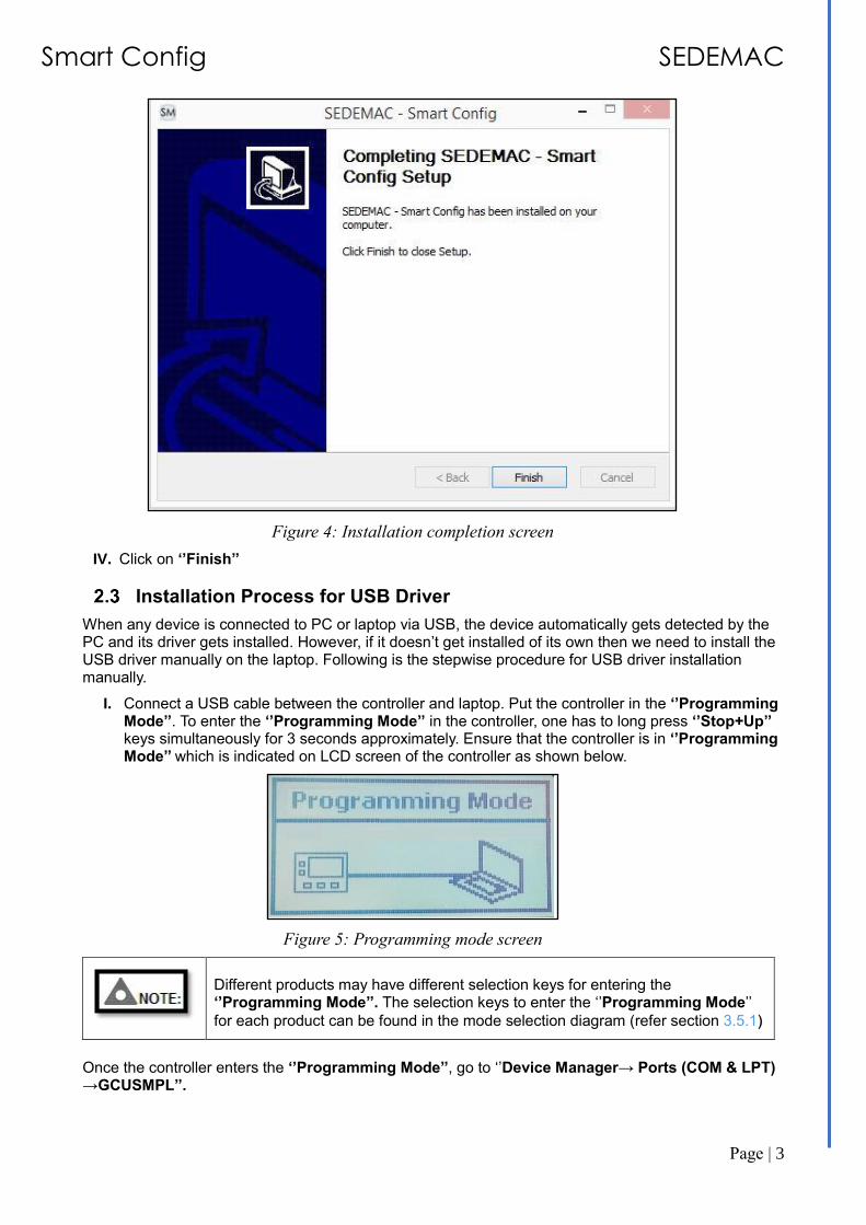
Figure 4: Installation completion screen
IV. Click on ‘’Finish’’
Installation Process for USB Driver
When any device is connected to PC or laptop via USB, the device automatically gets detected by the PC and its driver gets installed. However, if it doesn’t get installed of its own then we need to install the USB driver manually on the laptop. Following is the stepwise procedure for USB driver installation manually.
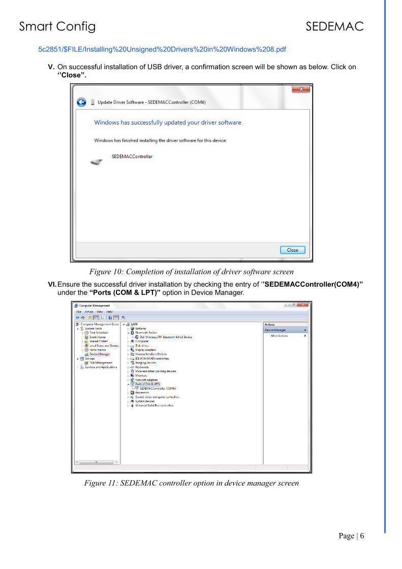
I. Connect a USB cable between the controller and laptop. Put the controller in the ‘’Programming Mode’’. To enter the ‘’Programming Mode’’ in the controller, one has to long press ‘’Stop+Up’’ keys simultaneously for 3 seconds approximately. Ensure that the controller is in ‘’Programming Mode’’ which is indicated on LCD screen of the controller as shown below.
Figure 5: Programming mode screen
Different products may have different selection keys for entering the ‘’Programming Mode’’. The selection keys to enter the ‘’Programming Mode’’
for each product can be found in the mode selection diagram (refer section 3.5.1)
Once the controller enters the ‘’Programming Mode’’, go to ‘’Device Manager→ Ports (COM & LPT) →GCUSMPL’’.

Smart Config SEDEMAC
Page | 4
Figure 6: Device manager screen
II. Right click on “GCUSMPL” and select “Update Driver Software”.
Figure 7: Update driver software screen
III. Choose “Browse my computer for driver software” to select the correct driver software.

Smart Config SEDEMAC
Page | 5
Figure 8: Search for driver software screen
IV. For driver installation on 64-bit Windows system, choose a driver path as “C:\Program Files(x86) \SEDEMAC” and then click on ‘’Next’’.
Figure 9: Browse for driver software screen
Please refer following links for Installing Unsigned Drivers in Windows 8.
Disabling Driver Signature Verification on 64-Bit Windows 8:
http://www.howtogeek.com/167723/how-to-disable-driver-signature-verification-on-64-bit-windows-8.1-so-that-you-can-install-unsigned-drivers/
Installing Unsigned Drivers in Windows 8:
http://my.okidata.com/idocs2.nsf/f7f729f023d5f3b785257706006556ac/49724794617ca7c885257acb00
Smart Config SEDEMAC
Page | 6
5c2851/$FILE/Installing%20Unsigned%20Drivers%20in%20Windows%208.pdf
V. On successful installation of USB driver, a confirmation screen will be shown as below. Click on
‘’Close’’.
Figure 10: Completion of installation of driver software screen
VI. Ensure the successful driver installation by checking the entry of ‘’SEDEMACController(COM4)’’ under the “Ports (COM & LPT)” option in Device Manager.
Figure 11: SEDEMAC controller option in device manager screen

Smart Config SEDEMAC
Page | 7
Usage Instructions
Starting with Smart Config
Run the Smart Config installed on your system. Start-up screen will be displayed as shown below.
Figure 12: Start-up screen
The screen prompts the user to select between two options as follows.
OPTION 1:
Create new configuration and select your product:
Select the appropriate series (EG or GC series) depending upon the type of product (for example, GC 1200 is from GC Series), for which the configuration is to be deployed.
Example: Let’s take the example of GC1200 controller
As in the example we have taken GC1200 controller, so we need to select ‘’GC 1X Series’’ as shown below.
Figure 13: Create new configuration screen
Smart Config SEDEMAC
Page | 8
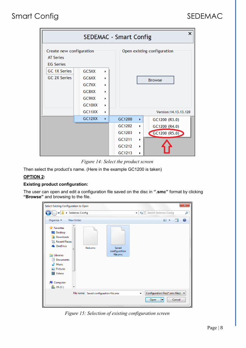
Figure 14: Select the product screen
Then select the product’s name. (Here in the example GC1200 is taken)
OPTION 2:
Existing product configuration:
The user can open and edit a configuration file saved on the disc in ‘’.smc’’ format by clicking “Browse” and browsing to the file.
Figure 15: Selection of existing configuration screen

Smart Config SEDEMAC
Page | 9
Application behaviour in case of an incompatible device
A device is said to be incompatible in following conditions
• The controller revision and Smart Config product revision mismatches (e.g. GC1200 R4.0 in GCU and GC1200 R5.0 in Smart Config)
• The product selected on Smart Config is different from the controller. (e.g. GC1100 R4.0 in GCU and GC1200 R5.0 in Smart Config)
If the device is incompatible, then Smart Config gives a pop-up message.
Figure 16: Incompatible device pop-up screen
• Select “Yes” and connect the correct controller or change the revision/product to a correct one on the Smart Config
• Select “No” to close the Smart Config utility.

Smart Config SEDEMAC
Page | 10
Figure 17: Incompatible device error message screen
Working with SEDEMAC Smart Config
A configuration is a set of parameter values determines behaviour of the controller. There are some options which help to create, open, view, save, etc. the configured parameters. They are all grouped under ‘’ File’’.
Figure 18: File menu
Smart Config SEDEMAC
Page | 11
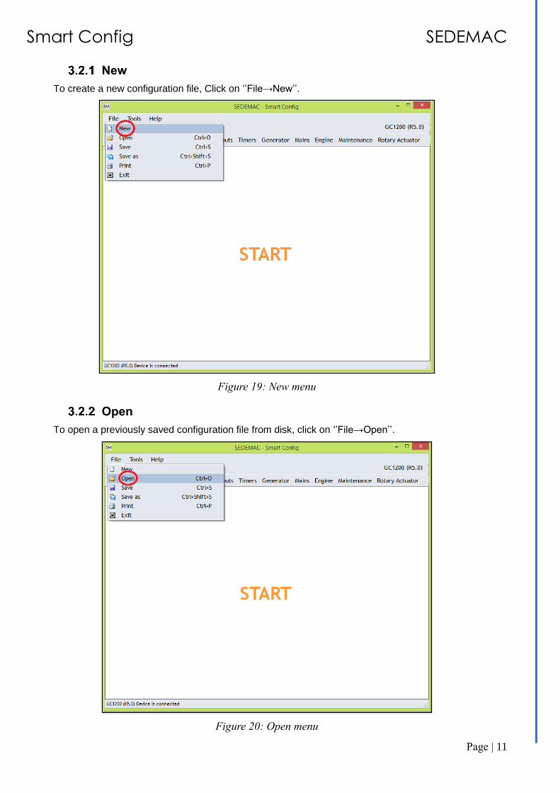
New
To create a new configuration file, Click on ‘’File→New’’.
Figure 19: New menu
Open
To open a previously saved configuration file from disk, click on ‘’File→Open’’.
Figure 20: Open menu

Smart Config SEDEMAC
Page | 12
Save/Save as
To save the current set of parameter values as a configuration, click on ‘’File→Save’’. Also, we can change the name/location of the saved file by clicking on ‘’File→Save As’’.
Figure 21: Save menu
Figure 22: Save as menu
Smart Config SEDEMAC
Page | 13
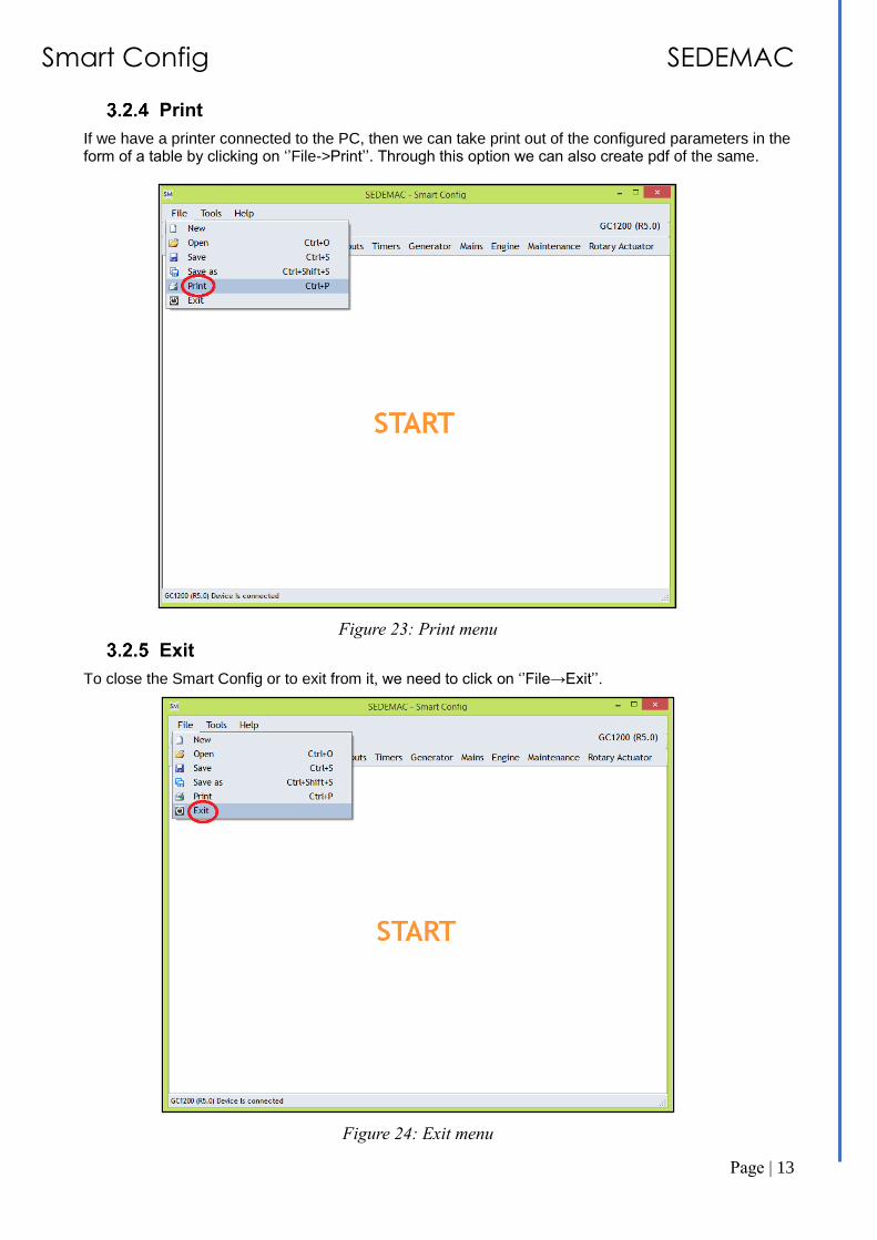
If we have a printer connected to the PC, then we can take print out of the configured parameters in the form of a table by clicking on ‘’File->Print’’. Through this option we can also create pdf of the same.
Figure 23: Print menu
Exit
To close the Smart Config or to exit from it, we need to click on ‘’File→Exit’’.
Figure 24: Exit menu
Smart Config SEDEMAC
Page | 14
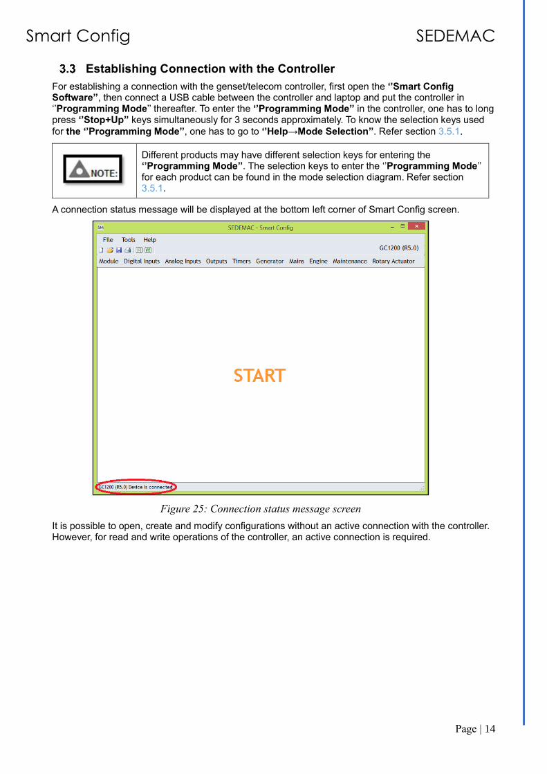
Establishing Connection with the Controller
For establishing a connection with the genset/telecom controller, first open the ‘’Smart Config Software’’, then connect a USB cable between the controller and laptop and put the controller in ‘’Programming Mode’’ thereafter. To enter the ‘’Programming Mode’’ in the controller, one has to long press ‘’Stop+Up’’ keys simultaneously for 3 seconds approximately. To know the selection keys used
for the ‘’Programming Mode’’, one has to go to ‘’Help→Mode Selection’’. Refer section 3.5.1.
Different products may have different selection keys for entering the ‘’Programming Mode’’. The selection keys to enter the ‘’Programming Mode’’ for each product can be found in the mode selection diagram. Refer section 3.5.1.
A connection status message will be displayed at the bottom left corner of Smart Config screen.
Figure 25: Connection status message screen
It is possible to open, create and modify configurations without an active connection with the controller. However, for read and write operations of the controller, an active connection is required.

Smart Config SEDEMAC
Page | 15
Tools
The Smart Config allows a set of actions to be performed in addition to editing and saving the configurations. These actions can be accessed under the ‘’Tools’’ menu, as shown below. These actions are enabled only if an active connection with a controller is detected.
Figure 26: Tools menu

Smart Config SEDEMAC
Page | 16
Write config to device
To write the currently chosen configuration in the controller, click on ‘’Tools→Write config to device’’.
Figure 27: Write config to device menu
On selecting this action, pop-up window will be shown as below, which summarizes the existing values of the parameters.

Smart Config SEDEMAC
Page | 17
Figure 28: Write to device screen
To write the values, choose ‘’Write To Device’’ option. The configuration will be written in the controller.
Figure 29: Writing configuration on the device screen
A confirmation window will pop up once the writing process is completed.
Figure 30: Configuration utility writing completion screen
Read config from device
To read the configuration of controller click on ‘’Tools→Read config from device’’.

Smart Config SEDEMAC
Page | 18
Figure 31: Read config from device menu
Select ‘’Read From Device’’ option. The configuration will be read from the controller and appropriately populated in the Smart Config.
Figure 32: Read from device screen
A confirmation window will pop up once the reading process is completed.
Figure 33: Configuration utility reading completion screen
Update firmware on device
To update the firmware in the controller without affecting configuration of the controller, click on ‘’Tools→Update firmware on device’’.
This feature is currently available only for GC1031.

Smart Config SEDEMAC
Page | 19
Figure 34: Update firmware on device menu
Click on ‘’Update Firmware’’ to flash the latest firmware on the device.
Figure 35: Update the latest firmware screen
A confirmation window will pop up once the firmware updating process is completed.
Figure 36: Firmware update completion screen

Smart Config SEDEMAC
Page | 20
Read event log from device.
Figure 37: Read event log from device menu
To read and display the event logs in the connected controller, click on ‘’Tools→Read event log from device’’. It will give the description of the last 100 events (like engine start, engine stop, actuator failure, etc), their date and time of occurrence and the respective reading of the engine run hours.
The pop-up window will appear as below. The event log can also be saved to disc in a PDF format by clicking on ‘’Save As PDF’.
Figure 38: Save as PDF screen
All devices do not have 100 events, also the number and name of columns in Event Log are not same across all the devices.
Smart Config SEDEMAC
Page | 21
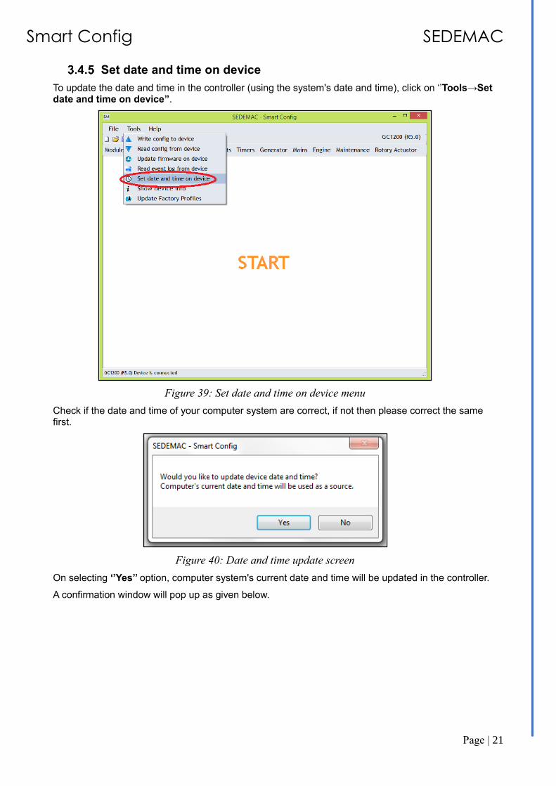
Set date and time on device
To update the date and time in the controller (using the system's date and time), click on ‘’Tools→Set date and time on device’’.
Figure 39: Set date and time on device menu
Check if the date and time of your computer system are correct, if not then please correct the same first.
Figure 40: Date and time update screen
On selecting ‘’Yes’’ option, computer system's current date and time will be updated in the controller.
A confirmation window will pop up as given below.

Smart Config SEDEMAC
Page | 22
Figure 41: Date and time update confirm screen
Show device info
The details about the product, software and other details in the controller can be seen by the user using this function by clicking ‘’Tools→show device info’’ after connecting the controller in the ‘’Programming Mode’’. To enter ‘’Programming Mode’’ please refer section 3.5.1.
Figure 42: Show device info menu
The following window will pop-up.
Smart Config SEDEMAC
Page | 23
Figure 43: Device information screen
Device Info displays different information for different devices and revisions.
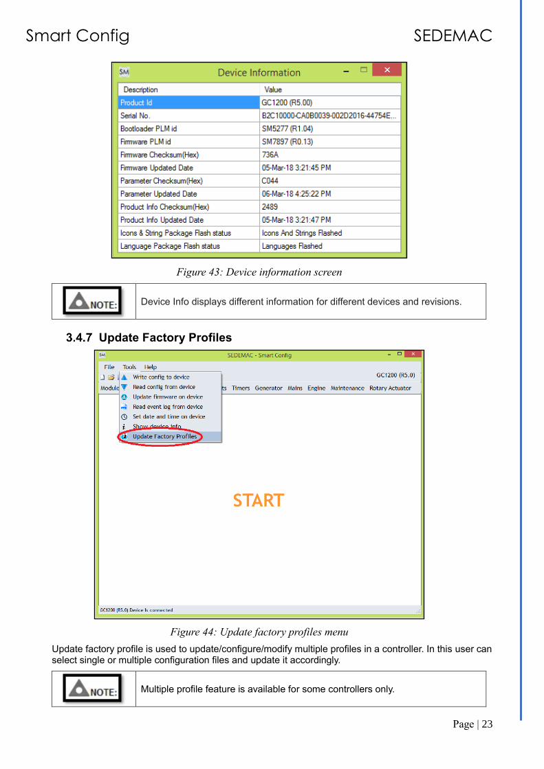
Update Factory Profiles
Figure 44: Update factory profiles menu
Update factory profile is used to update/configure/modify multiple profiles in a controller. In this user can select single or multiple configuration files and update it accordingly.
Multiple profile feature is available for some controllers only.

Smart Config SEDEMAC
Page | 24
User can update any profile number, even in between profile numbers or all profile numbers as per the requirement.
Figure 45: Updating factory profiles screen
Tools tips
There is a provision in our GUI software which will help the user to understand the parameters and effect of the same while configuring the controller. When one will keep the cursor of the mouse on any parameter, an information bar appears which will give a brief description of that parameter. Below is an example which describes how the tool tip for actuator speed gives the information regarding ‘’Actuator Speed’’.
Figure 46: Tool tip example screen

Smart Config SEDEMAC
Page | 25
Help
The Smart Config also has some information and data stored in ‘’Help’’ which help the user in understanding the product to configure the device in a better way. It can be viewed even without connecting the device. It gives information regarding the selections keys for different mode selections. It also gives information about the device like the ‘’ name of the product’’, ‘’version of the software used’’, etc.
Figure 47: Help menu

Smart Config SEDEMAC
Page | 26
Mode selection
To know about different modes of the controller, the keys used for the selection of modes, etc., click on ‘’Help→Mode Selection’’.
Figure 48: Mode selection menu
An image will pop up as shown below
Figure 49: Controller mode selection screen
Smart Config SEDEMAC
Page | 27
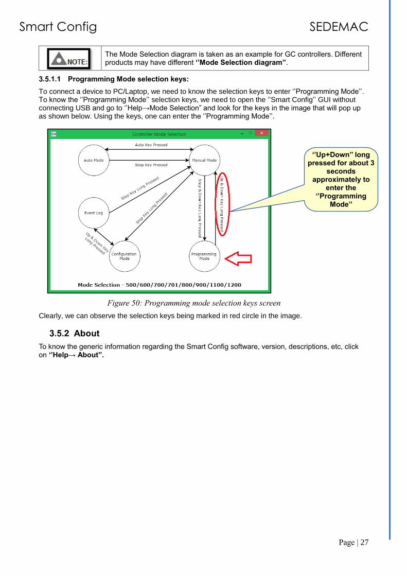
The Mode Selection diagram is taken as an example for GC controllers. Different products may have different ‘’Mode Selection diagram’’.
Programming Mode selection keys:
To connect a device to PC/Laptop, we need to know the selection keys to enter ‘’Programming Mode’’. To know the ‘’Programming Mode’’ selection keys, we need to open the ‘’Smart Config’’ GUI without connecting USB and go to ‘’Help→Mode Selection” and look for the keys in the image that will pop up as shown below. Using the keys, one can enter the ‘’Programming Mode’’.
Figure 50: Programming mode selection keys screen
Clearly, we can observe the selection keys being marked in red circle in the image.
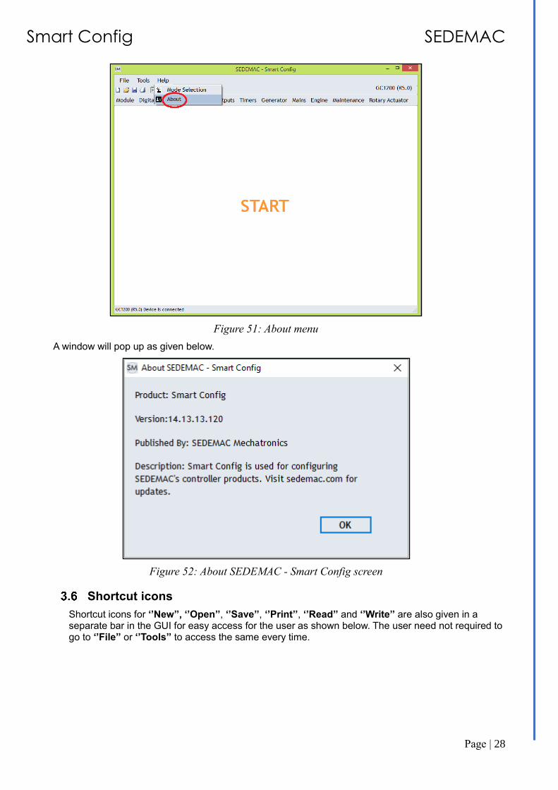
About
To know the generic information regarding the Smart Config software, version, descriptions, etc, click on ‘’Help→ About’’.
‘’Up+Down’’ long pressed for about 3
seconds approximately to
enter the ‘’Programming
Mode’’
Smart Config SEDEMAC
Page | 28
Figure 51: About menu
A window will pop up as given below.
Figure 52: About SEDEMAC - Smart Config screen
Shortcut icons
Shortcut icons for ‘’New’’, ‘’Open’’, ‘’Save’’, ‘’Print’’, ‘’Read’’ and ‘’Write’’ are also given in a separate bar in the GUI for easy access for the user as shown below. The user need not required to go to ‘’File’’ or ‘’Tools’’ to access the same every time.

Smart Config SEDEMAC
Page | 29
Figure 53: Shortcut icons screen
Configurable parameters
There are many parameters for example, ‘’Digital Inputs’’, ‘’Outputs’’, ‘’Generator’’, ‘’Mains’’, ‘’Rotary Actuator’’ etc. which can be set and initialized according to the needs of the user and the application.

Smart Config SEDEMAC
Page | 30
Figure 54: Configurable parameters screen
Editing Parameters
Following are the options available for editing parameters.
Figure 55: Editing parameters screen
• Check box
Check box is typically used to enable/disable a feature.
• Text entry box
A value can be directly entered in a text entry box.
• Increment/Decrement arrows
Increment/Decrement arrows can be used to progressively increase/decrease the corresponding value.
• Slider
A slider can be dragged to change the corresponding parameter value
Primary level (Level 0) parameters
Secondary level (Level 1) parameters
Tertiary level (Level 2) parameters
Increment/Decrement Arrows
Slider
Check Box
Text entry Box

Smart Config SEDEMAC
Page | 31
Troubleshooting
Table 1: Troubleshooting
Sr. No.
Faults observed Remedial-Actions
1. The user driver is not detected. • Re-install the user driver as given in the manual. Refer section 2.3
2. • ‘’Read’’ and ‘’Write’’ icons are not visible.
• No options is visible.
• Ensure that the controller should be put into ‘’Programming Mode’’ To enter ‘’Programming Mode’’ refer section 3.5.1 only after opening of the smart config GUI.
• Ensure that the right controller’s name with correct version is selected in the the GUI start-up screen or else the following window will pop up. Press ‘’No’’.
3.
Error in reading from the device or any communication problem.
Disconnect the USB and reconnect it once again.

Smart Config SEDEMAC
Page | 32
Disclaimer: Due to continuous development, the details provided in this document are subject to change without any prior notice.
SEDEMAC Mechatronics Pvt Ltd Technical Centre
C 9-10, C Block, MIDC Bhosari Pune 411026, India
Manufacturing Plant
G-1, MIDC, Phase-III Chakan Industrial Area, Nighoje
Pune 410501, India
Manufacturing Plant Survey No. 64/5, Off Sinhagad Road
Vadgaon Budruk, Narhe Pune 411041, India