manual mc vmc2240xl
TRANSCRIPT

ACER OPEARATION MANUAL
Vertical Machine Center
Model: VMC-2240XL
TAIWAN: FORMOSA SPRINGWOOD INTERNATIONAL, INC.
NO. 101, 506 LANE SENG-TSO ROAD, SENG KARNG
SHARNG, TAICHUNG COUNTY, TAIWAN
TEL: 886-4-520-4120 FAX: 886-4-2520-4123 WWW.ACERONLINE.NET NJ: KLIM INDUSTSRIAL, INC. 244N. RANDOLPHVILLE ROAD PISCATAWAY, NJ 08854 USA TEL: (732)752-9100 FAX: (732)752-9101 WWW.ACERONLINE.NET CA: SPRINGWOOD INDUSTRIAL, INC. 1062N.KRAEMERPLACE ANAMEIM, CA 92806 USA TEL: (714) 632-9701 FAX: (714) 632-9701 WWW.ACERONLINE.NET 2008.08.01
kh-4- + A $ *rfBlfk ................................................... 1-1
$ j&&$R$& ................................................... 2- 1 4- + $ $la *&&+@ ................................................ 3-1
$ W $ ~~a~tsljgrn n;;e .......................................... 4- 1
$x$ j$~,f~&*%jf$q- ............................................. 5- 1 2-4- $ .. a j$l+1G$&2%jta8 ............................................. 6- 1
$%$ 4 t . A A k n a ) I ... v ................................................... 7- 1 4- J i g g & + / h f l $/la ,. GJZ R, &jilk& .......................................... 8- 1
MENU
CHAPTER 1
CHAPTER 2
CHAPTER 3
CHAPTER 4
CHAPTER 5
CHAPTER 6
CHAPTER 7
CHAPTER 8
................................ Safety precautions 1-1
............................ Machine specification 2- 1
..................... Installation and preparation 3-1
............. Maintenance schedule & oil chart 3-1
.............................. Technical reference 5- 1
.................................. Operation panel 6- 1
......................... Command introduction 7- 1
................ Alarm description and solution 8- 1

CHAPTER 1 SAFETY PRECAUTIONS
* * * # ~ ~ ~ ~ ~ # & & * $ g * ~ ) l ~ b ~ A g ghlk$& \ ~+$$&$$@*&~* * **THIS MACHINE MUST NOT BE SERVICED, REPAIRED OR MAINTAINED
BY UNQUALIFIED AND UNTRAINED PERSONNEL.**
&j& z g g < + 3 *+;$$&*i@kjaA&j&%ig*4g g&&@ O $$4$ %T &43i42iR$fi kL % *+<R$b, fi a&<% 22 j' @CAT&* -$: WRI $&% R*k44%$%4+*+&&
This machine is equipped with a number of safety devices to protect personnel and equipment from injury and damage. Operators should not, however, rely solely upoil these safety devices but should operate the machine after fully understanding the following paragraphs.
S - % f i Z , ~ ~ $ t N $ % 4 $ & , $ @ @ 5 4 ~ 4 ~ CNC j&%4$$$fiv4EIA&5S4i!$ g #Jq-R*k't&, &AAi&p$& !$Jig# &+ O ,4$$3?~3+4i#fRfh9;z~&$~ +?g$+j&g$%4$N $%&$3*%, 4$+j-f&j&$Ffiv1fl+ra~ \ $gg &jg&+& &%$$4+j& %~Z+'t!k O &$F LflA 5R~&&flAfi+$%4+#fRfk, 4 i d % % A t ~bk$j-$Z#k%-?!k$%4$/~h$1k h
Moreover, improper operation and maintenance of any CNC machines increases the likelihood of serious personal injury and greatly reduces the service life of this machine. Your attention to this manual, in combination with common sense and good machining practice, can positively affect productivity by reducing downtime and promoting safe operation of this machine unless they are explicitly stated in this instruction manual.
3f$??$.$+3&g# # J J ~ & , &f{+f iuNZ2%g El *$h$$jfiv CA 8~&, $5 &*$j- Bfl*+4+$ggg$+&~l/#h O
Additional safety considerations inay be required for your particular application. Please refer to safety information for additional information and reference publications.
** 9 9 gj RULE OF THUMB :
1 . *49a4+g$&*Ag ?$k$*$g&4%4++4%% O
Only qualified persoilnel are permitted to maintain and operate this machine.
2. $k4%4+&@32+4%%, &jk4$ Lfk73$37F#Pfi4+%g++Xf437? 4&e4_*FiJr*g%X3$%3Z$g O
Do not operate or attempt to repair the machine until you have read and understood all manuals that pertain to the machine, plus all warning and instruction plates /decals mounted on the machine.
3. $g$$glb&=4+3p&fl+;&&$* O +;g&+g L g g l ] @$JJ&fi,~*%gg, $g@4%4+&$@fg+4& % O
Be mentally alert on the job and keep safety in mind. Never attempt to operate or repair a machine if you are under medication or alcohol influence.
4. && %*=4+$Z !El El, 2g $&g*$kA4%2g$t, $*$k!%3$R&+ZiEb #I&, fi4%$gg@$&t~Jq & &$E$ &* O
Wear safety shoes and eye protection within the work area. Safety shoes should be oil-resistant and safety glasses with side shields are strongly recommended.
5. ?g@j$@+& - S3?&h$X~&@4+4%4+4%%, JA@%4&+&%$5% I + Q ~ A O Remove watches, jewelry and other accessories to avoid getting them caught in moving parts.
6. &4&% mfli%d$$Li$-, =4+&32&@ o
Maintain a clean and orderly workspace around machine.
7. i&?git!3%&73 gXg&fl34+, $g@<2& e m f l !El &#$h O
Store tools and miscellaneous parts properly. Be sure there are on articles around the machine.
8. ~ ~ @ { ~ H ~ & % 2 $ & & & 2 + ~ & $ & - =4+$ - S + j & & a&$G&i& + ~ % Q A , mernqq-w+ql]A k p + ~ f i $g@ &4g~~+ez &g& $&$if% fl+&fi, 3%*$?73 R?E*4+k-+$%4&*hv $A ; $ p + J f i , 33-% $9 $ 43lJ +J f i O
Do not use compressed air to blow chips from the machine spindle or table, coiltrols, cabinets, or the floor around the machine. Use a brush or chip scraper to remove chips. Do not remove chips by hand or while the spindle is turning. Make sure that the cutter has coinpletely stopped before attempting to remove chips. Dispose of chips frequently.

9. $$zg$&&js-4+&&fl$) 3E?t$TTEk%+&%) $33k2$&82++-@36f~~q? Y, T$k@k% O
Never start the machine when the cutter is in contact with the workplace. Make sure the direction of spindle rotation is correct to prevent cutter breakage.
l0.*9,&~SFFi%)' %&4+Jk4a7' FFi&4iLE> + % % h ~ s - 4 + % 9 ~ &fiiHFFi gs t la~ , ~~+w+wzxz ,m~ a7 Know where all the EMERGENCY STOP pushbuttons are located. Keep all machine doors closed while the machine is in operation, including those on the console and the electrical cabinets.
11.++$&4+%) & f L E p f i i MZifi\ O In the event of power failure, turn off the main circuit breaker immediately.
12.%$F+& %-tPq?L 9 C % X $ 4 6 t l i & E ; & & L ~ $ H 2 ? k & % 4XS) 5 ElJ TTEk%+&% O
Do not start the machine unless all units contain the proper amount and type of hydraulic oils, lubricant or acceptable equivalents.
~~.T#$~&&N~%@~,$,~B~$$$N$RXE$$LB o
Fuses replacement should have the proper current ratings.
1 4 . $ ~ & &$$+$k $k3&g&z+,xa -+@i o +~&@%Ezk, 583?45L %%,:~&+a 88 2%) ~;Z42fi~4&$2%$H Do not change parameters, volumes and other electrical setting unnecessarily. If such changes are unavoidable, record the values prior to any adjustments for future reference.
15.52& ;% % % ~ 4 ~ & ~ ~ T - t P ~ %+$#) + C @ & & ~ & ~ $ ~ & , j + % ) 556f ~<Z~%P#$A&T% Do not soil, scratch or remove the caution plate. Should it become illegible to read or missing, order another caution plate from the supplier.
lfj.%++j+3@&+& A.$.&,&&!L$~~~U$) ~ % / J \ I C LX~@%@*&A&J&~~
H4hS O
Whenever operating a forklift truck, crane or similar equipment, special care should be taken to prevent collisions and damage to surroundings.
17.$8&sd&+&&A?,?,hfiT@$$) j~$$$&Es$$j+#$ 9) $f$-@ $$$ o
Do not leave machine unattended, but stand away while it is run~ling.
1 8 . 6 a s-4+$&% #E+j a$, <f$-A423i$.fii h-'1 o
Turn off the power source before leaving for the day.
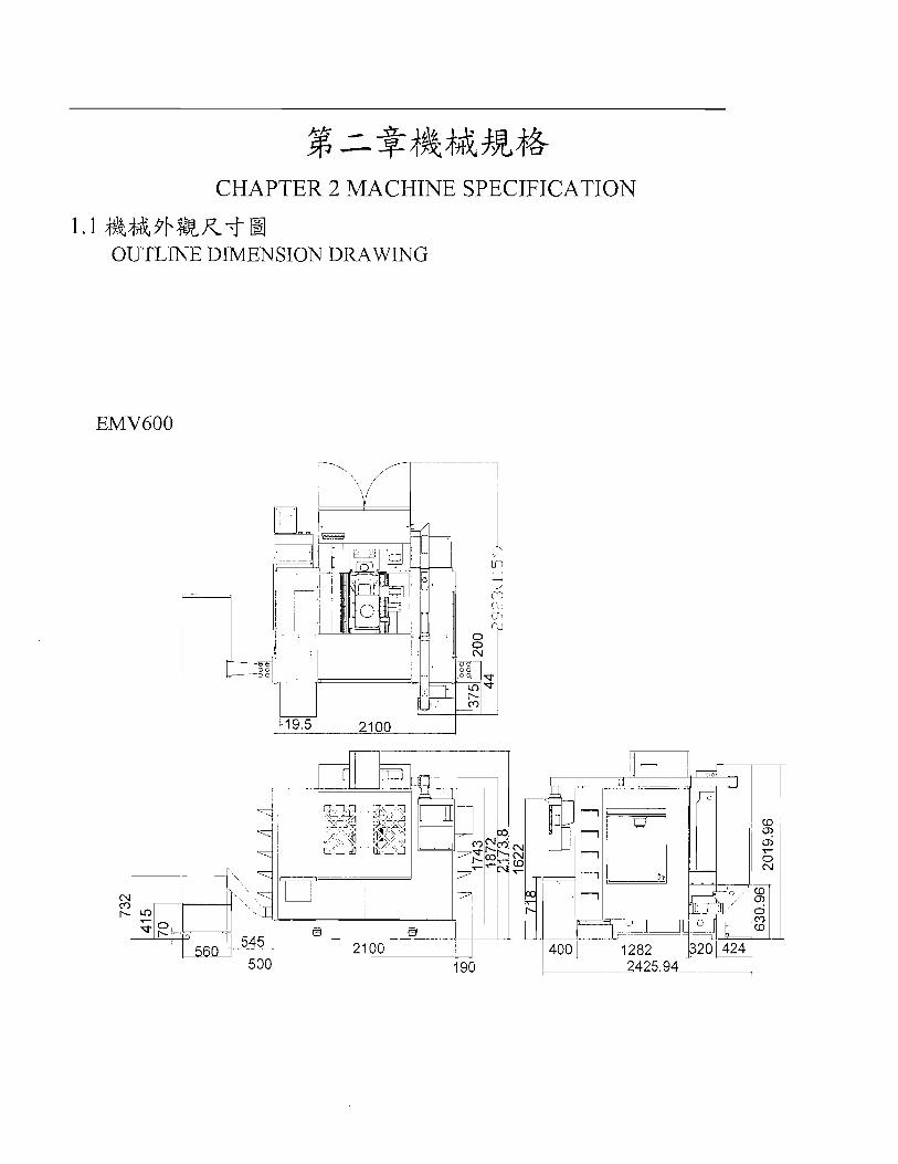
CHAPTER 2 MACHINE SPECIFICATION
1.1 #&$&91&R-f OUTLINE DIMENSION DRAWING

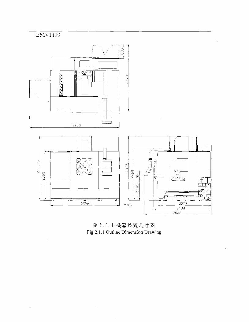
2 , 1 . 1 & Fig.2.l. 1 Outline
%3+4&R-j-a Dimension Drawing

2.2 $&+&&4p4&4& j!? ,g The main parts of machine ,and the position of operator
No.(E?%!) Gf@ Description 1 % ~ Q'ty %$BE Spindle (1 C$Z Column 1
3 1 Table @ Saddle 1 1 % Base %$h Spindle 1 % $ B , B ~ Spindle 1 motor
UU kk 'saFB Electrical Box
1

x $Ill739 m Max. travel for X axis
y $ER7?@ mxn 3@!732 Max. travel for Y axis
T ravel
I Spindle nose to table I 8000: 1 O O O O ( s E ) (Optional)
/ 1 2 0 0 0 ( 3 ~ ) (Optional)
q%s M e s s 1 6Tl 7Jgs ~ r m 2 4 T ( g E )
(Optional)
z$$ Spindle z@$$g Spindle speed 1 rpnI
Tool Q'ty
~MZAnEB73
ATC Max. Tool Leneth .? ZAngsz Max. tool Welght kg
nSi3t8 Tool Shank
z$$,%g Spindle motor
motor
Table
T-slot (Center * width * NO.)
x $ER1['RZl?i@ X-rapid traverse
24 $$$A Linear way136 #$a Linear way (ZE) (Optional)
24 $&$$A Linear way136 #$a Linear way (ER) (Optional)
Y @'RB{?i$% Y-rapid traverse
Rapid travel 20 $$$A Linear way124 48% Linear way (gE2) (Optional)
L V Y 111111 I Z-ra~ id traverse (@%I,) 1
1 Cuttine feed rate 1 LA-LU L I L I L I L
@%!I% 1 3% Mitsubisl~i Controller
1 $gggs Machine weight 1 kg
Othet
3s' elf$%$? Power Requirement A P T - '
KVA c)&yR Air Requirement ICg/cm2
t ik$EBf coolan tank 1 L

T ravel
'- a -Bh-r~k
s$fi Spindle
I I .&-A.
Max. travel for Z axis
x @734 Max. travel for X axis
y @?TjF:Z Max. travel for Y axis
b $ @ t f a sindl; . r n l 8000: 11 2 o o o ( g 8 2 ) 1 0 0 0 0 ( g ~ ) (Optional)
m
m
Spiudle nose to table
860
550
111111 I 1 u - I - I U I
nHBElnB9s Tool Q'ty
PCS q%s Armless 16TI
7Jgs ~ r m 2 4 T ( g E ) (Oational)
BBnB2 #%#R
ATC
wlilEAnBB73 Max. Tool Diameter
,%B motor
EAnsEE Max. Tool Length
z A n B s 3 Max. tool Weight
I f W Max. table capacity
Table
T-slot (Center * width * NO.)
m
nBBt8 Tool Shank
s@,Rg Spindle motor
(E,@13 0 fif&%t&) X/Y/Z @,FB
XTY/Z servo motor
Table size
Jl%%i3i% Rapid travel
@%g% Controller
120
mm
kg
kg
f €3 Othet
3 00
6
kw(Hp)
kw
mm
800
I
x ~PRBfG% X-rapid traverse
Y $fiJRBfG% Y-rapid traverse
Z @JRBiG@ Z-rapid traverse (@a)
$yBLIjgtfiBB Cutting feed rate
=@ -+ Mitsubishi
BT40
7.511 1kw
1.511.512.0
910x560
5x18~100
$gsgB Machine weight
ZjE%$? Power Requirement
2l@:@ Air Requirement
7k$E733 Coolan tank
M/mm
Wmm
M/mm
mm/xnim
24 $$a Linear way136 $$a Linear way (EE) (Optional)
24 $$a Linear way136 $$a Linear way (ge) (Optional)
20 $$a ine ear way124 $,$$A Linear way (BE) (Optional)
1110000
64SM
kg KVA
Kg/cm 2
L
5800 2 0 6
200
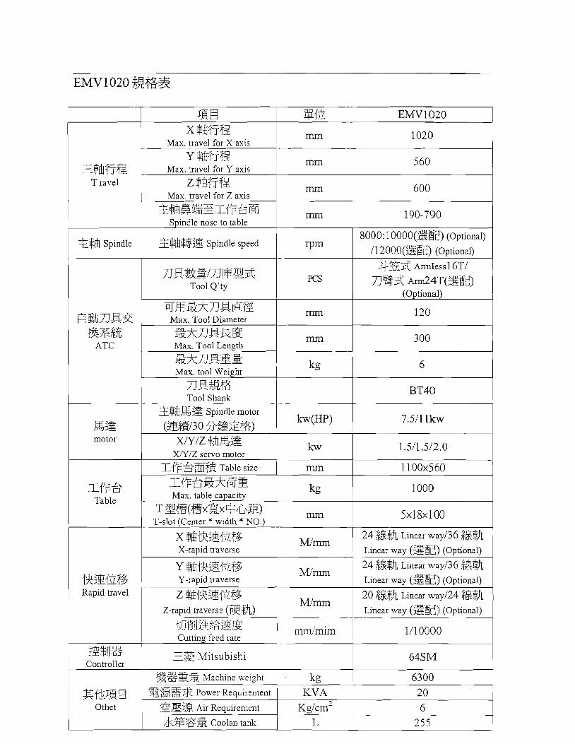
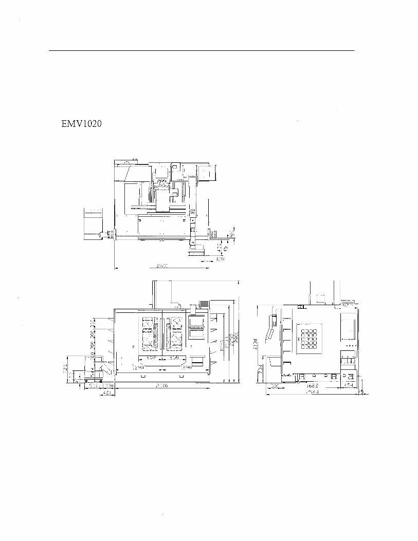
EMV 1020 Bif:%%
JB €I EMV1020 I x $b77f5!
Max. travel for X axis
?$b?T@ T ravel
Spindle
n E+Bt% Tool Shank
mm
y $t877fZ Max. travel for Y axis
Z $Q??fiZ Max. travel for Z axis
3a%G%zI!Fsm Spindle nose to table
%@$!$B Spindle speed
f l ~ B S ~ L ~ E 2 3 Tool Q'ty ~ ~ r n ~ A n m m
BrnTJm? Max. Tool Diameter
"
EAnEBSi Max. tool Weight
1020
mm
mm @%if;:% ATC
motor
! mm
mm
mm
rpm
m
120
300 EAnEEE Max. Tool Length
kg
,gg m l z $EB,Fgg
X / Y / Z servo motor
560
600
190-790
8000: 10000(g@) (Optional)
I1 2 0 0 0 ( g E ) (Optional)
.'CE$ Armless l6Tl
TJgi%, ~ r r n 2 4 T ( g E ) (Optional)
6
I Y F 3 Table
$$$,sg Spindle motor
(2E@130 fi@Zt%)
JRzgiG@% Rapid travel
?2%!J% Controller
kw(Hp)
MilJB €I Othet
7.511 1kw
1000
5x18~100
A kg
24 $,$I@, Linear way136 $$%
Max. table capacity -
T ~ @ ( @ X E X + I L \ E ) T-slot (Center * width * NO.)
Y $Ia3l$?BiG% Y-rapid traverse
Z @jRB!$@ Z-rapid traverse (@$A)
mm
20 6
E'BZz Power Requirement I KVA
1/10000
"mm
Mlrnrn
zB$g Air Requirement
24 $7$5& Linear way136 88% Linear way (EE) (Optional)
20 $7f:$h Linear way124 28% Linear way (SR) (Optional) --
~ ~ l c m ~

EMV 1 1 00 $$$@%
x $h$T$l Max. travel for X axis
T ravel
%$@ Spindle
y $h$T$l mm Max. travel for Y axis S$EB$T$i
mm
2
1100
$B77B2 &%R
ATC
7117 6 Table
600
150-750
8000: 1 0 0 0 0 ( ~ ~ ) (Optional)
I1 2000(g$J) (Optional)
433 ~rrn less20T/
Z $EB$T$l Max. travel for Z axis
B LuJ Z@g~z$If76E Spindle nose to table
%$@$3g Spindle speed --
PCS
,RZ$ motor
lm
mm
Tin
ng3 ~rm24T(gEz) (Optional)
FJm%AnBB?% Max. Tool Diameter
5AnBEE Max. Tool Length
Sb'inBSs Max. tool Weight
nBBta Tool Shank
%@,R% Spindle motor
(B,@13 0 fiEzt&) W / Z $&,%Z$
XIYIZ servo motor
slfFe@@ Table size
mm
mm
ll&B{$@ Rapid travel
120
3 00
kg
k w ( H p )
kw
mm
E%rJ% ContToller
f Othet
6
BT40
1 lkw
2.0/2.0/2.0
T~FeEAmB Max. table capacity
T @@(@x%x$JL\E) T-slot (Center * width * NO.) --
X $&RZfG% X-rapid traverse
1200x600
Y @lR@lGf& Y-rapid traverse
z $Qillft%fG% Z-rapid traverse (@a)
ql8!JEiegE Cutting feed rate --
I.@ Mitsubishi
$$$%% 3 Machine weight
'%@%% Power Requirement
gE$$? Air Requirement
7&$&gS Cooian tank
kg
IllIll
M/mm
M / m
M/mm
rnnltinim
1200
5x18~100
24 $$$A Linear way
118 @@,Box way
24 $ $ ~ Linear way
/1 8 Box way
24 $&% Linear way
/ 1 8 @ @ , ~ o x w a ~
1/10000
kg KVA
~ ~ / c i n ~ L
64SM
9200 3 5 6
3 7 0
CHAPTER 3 INSTALLATION AND PREPARATION
3.1 p$ & 33 PRECAUTION
1. @,4g*%)l/$$L*+&2L4+% g. ,7f $L$%4+3@,%#4$ - **&E+h+a4lX<k 8bAlkfi ?@% O
Only trained, qualified, qualified workers should operate forklift trucks, cranes or similar equipment and apply slings.
2. <%&+&lkfi++%QPFj%z@*&BR-f, &.IQ'IB~~~&EI~L.~BXLX k%#%+z232 O
Use only wires of dimensions specified in the manual. They must be strong enough to support machine weights.
3. &&#% +zg, *9$Ciq 5 g$3+$?&% @$fi El O
Before hoisting the machine, fixed each unit securely.
4. 4& 5 6t1H ?~L.%E~%~+$L-$A~~EE~,J$ Maintain a clean and orderly surrounding around the machine.
5. &if% 6 Z&%%$Z,J$$~,%T~~T-@$~ &#k_t<"POWER ON" $3 O
"POWER ON" on the control panel can be pressed only after the complete installation.
6. $gA$47V;$gi&$gQ, %$A Be sure electrical cables and wires are not damaged during installation.
7. 33$4g, $gA$$&q;B&B4%&3%g3&5X$44k, &%_t&% O After installation, proper capacity should be checked before connection the wire to the power source.
8. i%j%&fi@,+%, Z$LXA~$;&$$;~&$!A$+$&%~PZ~%$& o <$@lk m * T Z z 4 t H h O Removing the anti-rusty oil by rags with paraffin or fuel oil before operating. Toluene compounds must not be used.

Never leaver the control boxes open while the power is on. A deadly high voltage is present which can cause serious injury.
3. 2 ,&%$$i da $9 SERVICE REQUIREMENTS
3. 2. 1 3 2f f 5 ELECTRICITY
+#$ % $R&Z& 200-240V 50 &, 60Hz 2!$ h TS@, $jj@{% @ $ 3 @ & + 5 % ~ ~ fi o 2!$h 25KVA o kozZ$i{%&%$E&#+ $$$%%,7,$$& 5 j 3 j k q f i , wlJT+$fi 8mm2zz& o &+$$$+$R&+ 3G sc-J343JG%Z O
The machine runs on tluee-phase, 200-240V, 50 or 60-Hz supply. Power supplied to the machine should not fluctuate inore than It5 %. The power required is 20 KVA. Using a minimum section of 8mrn2, the input power cable should be within 5 meters between electrical cabinet and power supply end. A separate earth ground is required.
'7)CT* 3. 2. 2 ZLR AIR
~ ? k Z ~ $ R 4 k f i ~ % & ~ $Lk$sc-J2,$%,@, Eh@&$? 85-100 psi(6-8kg/cm2) o (ko: El 3.1)
The air requirement for the machining center is a continuous clean, dry air at 85-100 psi (6-8 kg/cm2). (Ref. Fig 3.1)
BfiMWEl PRESSURE SWITCH
El 3.1 Fig 3.1

2,$iJZh&%~<Bh Rj fid&&$!&&$ifij%~%kX&&, fi C A ~ !
jz$$d+&9&~&i%j<2 giJZp;kka+, &t@h Rj fifl + g f i % ~ j ~ . g ~ f ~ ,3 <+-t-n@ 6 4f&#<fi%&t;Bh MiIi
NOTE: Excessive oil and water in the air supply will cause the machine to malfunction. The air filterlregulator has an automatic drain fbnction that should be empty in the bowl before starting the machine. This must be checked daily for proper operation daily. Also, excessive contaminants in the air line may clog the dump valve and cause airlor water to pass into the machine. The air pressure-detecting switch installed in the system is factory-set to assure the proper "signal". The drop of air supply to the soleiloid control valves will cause improper fbnctioning of the pneumatic actuators. Do not tamper with this switch.
1 3. 3 3% ix$R h ENVIPONMENTAL REQUIREMENTS
1. &j&+&@k]+'& %&gfi@&!,!,4fHJh,%s#$&;g~ O +%d+N3% j & % i & & f i f i 0-40' C
Avoid expose the machines to direct sunlight andlor near to a heat source, etc. Ambient temperature during operation should be 0 through 40°C.
2. &BkA+'j&%&gfi$g&ffi@4tANJh8%&%&;%&& O
Avoid installing machines in a location where the humidity fluctuates considerably and/or highly humid.
3. &BkA$j%%&gfi3&&&;$fi;&HJh#% O
Avoid installing machines in a dusty, misty location.
4. &@kA+&%Akgfi&%&%fiWi O
Install machines where is no vibration sources in surroundings.
5. f iA+'+&%&gfi?~~E&~%NJh&I, p J - & & & s $ M 4 h 3q O Jd3#k sc-J&j&fi;fB h $R& 5000kg/cm2
Install machines in a flat and smooth ground without or other particles. The nlinimum bearing pressure of the floor is 5000 kg/m2.
6. & . i @ k j & , % i $ ! ~ ~ ~ & j & b Q + j & o @Jh: ~ $ f i ~ $ ~ & , & ~ j ~ u ~ - ~ & $ f o
The machine must be protected froin electrical noise sources, such as electric welders and an electric discharge machine.
7. G$Rq$G;l$;f%%-#gJh, j4iJh#~~j;i$R& IOOohms L X T , R-#~J&A$G~E& +5&% O
Always grouild machine independently. The ground resistance is should be 100 ohms or less and the length of ground cable should be as short as possible.
8. 0 $ k % - I & & 3 ~ . 1 + 2 - F f i & . 1 ~ ~ 4 f i & 85dBA o
The noise level at the operator's position should be under 85 dbA.
9. #&~Ffi&<~h&~~fi&E$X$+@&AZn~-$k~/k693k4L&$F3&4L 7&j&$%$$$, ktq$&4g6k$+tq*$a3+$?d&% g 2 < ~ g f i #$+ O
Foundation should be constructed of either reinforced or non-reinforced concrete with thickness and consistency and should also be compatible to industry standard for its machine weight.
3.4 4% SETTING IN PLACE
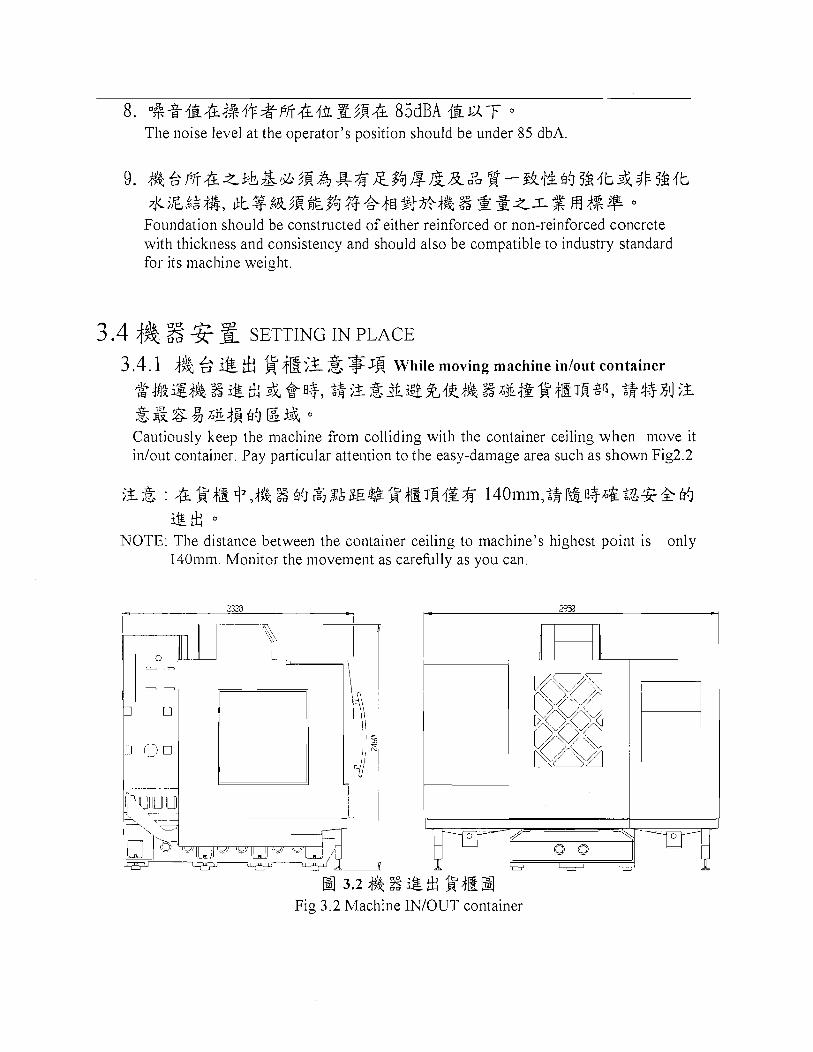
3.4.1 4% 2 @ & !$ +E$x 3 $JR While moving machine inlout container
$$#&igj& z i @ ~ &+I+, <$;g&&g%&#% %~&+gg$Ig~fi$p, <$++Xl];Z
,-, & 8 A&jE 69 @ i& O
Cautiously keep the machine from colliding with the container ceiling when move it inlout container. Pay particular attention to the easy-damage area such as shown Fig2.2
;Z& : & g#& +,& % 69 ,%j,%k~E$@g$E~fiIS$f 1401nin,$$P&fl+&g<%Z+69
i@* O
NOTE: The distance between the container ceiling to machine's highest point is only 140inin. Monitor the inovement as carefblly as you can.
a 3 . 2 & % $ & $$'$Ea Fig 3 2 Machine INIOUT container

3.4.2 & 4% By Forklift
?&a+;&%#%. % <SlGFfi&4&Z : ~ ~ 3 & & # % . a ~ , ~ ~ ~ ~ $ $ 3 k # & % % ~ G F f i & 4 & Z j k $ ~ $ # & % ~ & ,
4% Z4%4S!J O ( k ~ : a 3. 3) Keep in mind the machine's center of gravity: Approach the machine with a forklift at the heaviest point of the macline to avoid tipping over of it. (Ref. Fig 3.3)
**$&Sfl$, @$k%% EI %t&a#%#g(ATC)H-4flij&~, El a#&% I%$ g l ~ i & ~ ATC - 484 o
**The only acceptable way to move the machine is to lift it from the A.T.C. side.
,!sj 3.3 3&&#%3P;tg%& Fig. 3.3 Transportation of Forklift

THE PROCEDURE OF MACHINE INSTALLATION 1. l+;t.%%&g*&%4&g O
Position the machine after setting down the machine to the adequate place. 2. 4&F?\?&%i&&,LgFfi%, %kg&G$@ih3?i&&~%$2-F$ O (An: El 3 . 4 )
According to the drawing of foundation, put the foundation pas under the foundation bolts to position machine. (Ref. Fig. 3.4)
AD.JUSTA3LE EOLT "74.
EMVGOO

EMV 1 020

EMVI 100
3.4 Jh&H Fig. 3.4 Foundation Drawing
** 9 $3 %n IMPORTANT NOTICES:
~~-~7;9+&&x;f ig~jh$g &j~z&~r$zb$ *$1,47- o
Service engineer must do following check and adjustment. 1. @+&@)g 3 Zi'Ri&k, $$-~g~$$,pg$JJG{kfi 7;!,q$)g{& 0
Must coilfirm the power voltage supply before connect the wire to transformer 2. @&& f: &?,-?(+$ &&)x~f4$&$ O (4w:H 3.5 Ft%Z+F/rh)
Reinove the shipping [Orange color] and screw. (Ref Fig. 2.5)
a 3 . 5 %+hBR&ga;i% Fig. 3.5 Shipping Assembly

3. g g M;f@ Installation of accessories: : a. ~ 1 % 7 k + % $ f i , 3&-&9,%$37k$iX$$%b& o
Mount the oil-water separation tank, and connect the hoses to coolant tank and to oil reservoir tank.
b. &@&4p ,55&X7k$i <$€I fifl%,%k O
Pipe coolant pump and coolant tank. : 34% f i 3g$jp&7k3g&, $gj+f3$9 Ed +I gj O
**NOTE : Open ball valve when using ring spraying.
=+I=-&? 3. 6 7k9 jj , THE PROCEDURE OF ADJUSTING LEVEL
1. Z$&@L$i,% O
Let three axes return to the home position.
2. ;gjzs-4+ 5, &1$7kFj&b El 2i&%kZfi~4+ 5 1 (b : El 3. 6) Clean the table surface and put the levels gauge on just the drawing shown. (Ref. Fig. 3.6)
3. 6 $$$%7k+;flg Fig. 3.6 Adjusting Level
3. ;flgJth&+x#2X+x+Ei, ~~@4%Jth&+x$24&fi&&%*hw#1 O
Adjust the foundation bolt and nuts to make the foundation bolts locate within the indent of pad.
4. B3-2k9h473$&8FL$i%%4+ 3 axes home operation again.
5. 39% X $&3+255mni R Y $&3-2001nm &, ;A&9th&+X#257k?4& Z 0 0 1 1 1 1 n l m O
Move X axis to '400n1m and Y axis to -250mm. Adjust the foundation bolts to ensure the bubbles of level gauges in the middle position and keep the deviation within 0.01 ilm.
6. 39% X $$& 0 ? k 3 + 3 1 0 1 n m ;ASJth&+Z#2424+1t-t=&.rhZ7)(FI& 4]&-1O. O5mm $'&El ~9 Move X axis to the zero position and -800nm. Adjusting the bolts and nuts until the bubbles difference between the two points within 0.05111111.

7. $$&I X $&3+430mm 4hz&, iFg& Y $&& 0 ,%3-400mm 3J$Sth&h%
$&ik$+&tz&4hz7k?i&i&$$9&20. 05111r1-1 i3 o
After returning X axis to +400inm, move Y axis to zero and -5OOmm.Repeat procedure 6 until the bubbles difference value between the two points within 0.05 nun.
8. 4j$ ?j?~th&h%$&Ah%$E o
Tighten the foundation bolts with nuts.
* !L"*#J .f.;x&,$Xfla 3.7 *&L %
POWER INSTALLATION DESCRIPTION
3 7 . 1 & $ Power Installation Description
+& $ s$g-z$gq$$g$~ -F &,%: Check following points before power supply:
1. Ffi* El Zi+2346% Remove all fixed parts.
2. Ffi*&&$(%&$)733&43 Check all connections are connected.
3. Ffi* 45sz3 Check all motor are installed.
4. ~$$,?.?lg&!g3&@ Make sure the voltage of power supply is correct.
** - = 5 - +gap++ijig~z~~~gs 220+15%6 jgrjfig~~~~ sgq, ~ & A R $$ja\@$a$$p ~ ~ ~ ~ $ $ & $ ~ ~ , ~ T $ $ & ~ ~ ~ $ ~ ~ & $ $ ~ &&, T '""hkM& 0 43- % ,..\ Mitsubishi and Fanuc notification Controller would be abnormal and alarmed if the supply power voltage over the range of 220+15%. Installation technician has to make sure the power supply is correct before turn on the power. If the power is abnormal, ask customer to improve. Don't turn on the power until the power is correct. Other the customer should take the responsibility of damage.

3.7.2 & $& 3 9 ,@ The step of installation
1. 2% +gaP$+s+qg ikH 220v 3
Mitsubishi and Fanuc controller 220V/3phase, and earth connection needed.
2. p(#t@)gg-$& 0
Transformer attached.
3. 3 8 O V ( 4 2 0 V & 4 6 O V ) ~ ~ % ~ % @ % o
Connect 380V(420V&460V) power to transformer.
4. $ q ~ ~ z i & ~ x 5 2 2 0 v < + p % & A ; ~ & $ ~ D T ~ F $ % :
Transformer output 220V power. Connect to machine as shown below:
"t< 4.5 . f --- .L ?< ,*- :,$ ;7;:3& ,I.
Transformer Circuit
Reconfirm the power voltage before turn on the power.
w telk iz @
(4 x @iJ
6. ~ ~ ~ $ ~ ~ @ $ ~ f i ~ ~ $ g ) g & & $ ~ t ~ 7 2% & 4-j-6 o
It would be user's own responsibility if connected wrong power voltage and caused damage.
3BO/dl Y d d D v
$*MM PWB wilch
F E E Trans i o m r
-
/ 22Dv 3 ~ ~ d ~ v /
220 v
-

CHAPTER 4 MAINTENANCE SCHEDULE & OIL CHART
4.1 4% &<t gi MAINTENANCE SCHEDULE
~ ~ . r & , a ~ , ~ % ~ B C 3 I j p ; * ~ t ~ ~ ~ . f j & , L % ~ I j p ; ~ ~ 25 h!Jq-$g-$$ O
The following maintenance schedule should be followed to assure continued dependable operation of your machine.
a $J INTERVAL
$ !3 DAILY
4% 3% JR a MAINTENANCE ITEM
A$&&;M;ff;F!i&j$2& C = ,I1 T,b$R&;f!!;ff$&$gj&&& O (h: a 3. 1) Check lube pump and F.R.L. lubrication tank level. (Ref. Fig. 3.1)
A & & z , % & $ R & € ~ $ ~ . , E ~ o (h: 3.1) Check air pressure at F.R.L. unit. (Ref. Fig. 3.1)
*AS&) A&&:,%& $a&€ El %49k &7k& O (+% & 3
Check automatic drain at F.R.L. unit. (The bowl sl~ould be empty.)
~ : ~ p 3 ; " /a 5 &B2$$9 \ 7k4$2&3$$n&t84€4&4 o
Clean chips fiom way covers, bottom pan and tool changer.
A$&&*%p**&& O Check coolant level.
As$"t*BC3,&t*;gsR&$&&4*&, &lL*l$~$f ';$7 "
Wipes spindle taper with a clean close tag and apply light oil.
g 3 WEEKLY
A$&& ;*;R%z3&%k€;&iJq O
Checklclean filters screen on heat exchanger.
Perfom necessary cleaning of machine. Do not use solvents.
Lightly grease the Geneva wheel and guide rails of the tool changer and drum tluough all tools. (for drum type)

7
33 %!I INTERVAL
I Lightly grease the fingerlpocket of tools
AEt&$4~;&&4&&;%$%7k$G
4% ~ii 8 MAINTENANCE ITEM
A$&&$#&%g+Es ~&@%&RCA$@ g $& $gj ; ~ z ; & %!%%;%&7k$$L~j&$fl
MONTHLY
I I Replace coolant and thoroughly clean the coolant tank. I
Inspect way covers for proper operation and lubricate with light oil, clean the upper screen o the coolant tank if required..
I A a Mobil v a c t r a # 2 ;&Sjfffi~?&[email protected]%, %Si%&&$k 1 & + a 7 .
I SD(MoNTHS I Lubricate counterweight chains with Mobil Vactra #2 over full length of chain. (If counterweight is used)
~ I Inspect chain for any abnormal wear or cracks. I
4. 2 $0 OIL USAGE RECOMMENDATION
6 +- ANNUALLY
Fa & g 5% & 0 I L USAGE RECOMMENDATION
A$&&+% 5&h!3Fa~zgEs&+~$~ Check ground impedance level.
A$#&. ;833&?&$4;%~&$&i&&d%H;& Drain, flush & refill spindle oil cooler tank (if applicable).
MOBLE
k j + ; H j@;& , . LUBRICATOR OF PNEUMATIC
ESSO SHELL CASTROL
DET LIGHT
MAGNA BD68 6 &;Hi@% $75 ~ AUTO LUBR I CATOR SYSTEM
FEBIS K68
TURBO TERESSO 3 2 T32 NUT0 H32
HYSP IN VG32 PERFECTO T32
CHAPTER 5 TECHNICAL REFERENCE
5 .1 @4&MId&r$hE4* PROXIMITY SENAOR SPINDLE ORIENTAION
, % 8 & O %-$&;z . lQf iq-~ ; t i f~& MI9 %%-$&,%S&&&%$&&%&$ktL4F 1: l H*%W+, <tZ L4%~;t%-$&3%H4Qg4k&n%g(5$8H fiij)<.lQg$$.l+&+, * ~ F S A % - $ & , ! E , i g ~ H & A , ~ ~ g 4 + ~ . l Q & + Orientation of the spindle is automatically performed for tool changes and can be programmed with M19. If the gear ratio between spindle pulley and main motor pulley is not 1:1, the spindle orientation is based on the detector (proximity) at spind.le, not on the encoder at the main motor side.
5.2 n % & 8 &t&nd%$&r@% SERVICE NOTICE OF ARM TYPE A.T.C.
g* ! ! WARNING!!
* 4 K + J Z & f i * H 3" @, %Big 8 z@ld&ni%$g*&&&&hR O
*IT IS EXTREMELY DANGEROUS TO OPERATE OR REPAIR A.T.C. WITHOUT SUFFICIEIYT KNOWLEDGES.
*@& .?$@ $f$&H A R ;5 fc*&%i--#%d+ o
*ONLY QUALIFIED PERAONNEL IS PERMITED TO SERVICE THE FOLLOWING OERATION.
* + $ ~ @ @ I $ ! J A R ~ & & % ~ z@ld&,JJ#i&$$$77%*HS$.$~& *UNAUTHOURIZED PERSONNEL SHOULD STAY AWAY FROM A.T.C. OPERATION AREA.

CHAPTER 6 OPERATION PANEL
m 2 k t l l 9C6f it
- - - - - -
EI 6.2- 1 ( f i % @ & ~ V ~ @ & i )
Fig 6.2-1 ouch Panel)
6.1-1 EMV600 Fjq$$&,$g.i+ & # ~ % ~ ~ ~
$,$$$ErT a
EMERGENCY STOP A. Press this button in emergency situations, i.e. when human
life is in danger or there is a risk of damage to the machine or workpiece.
1 B. After pushing down this button, all niact-line movements, such as feed and spindle rotation will stop immediately.

1 C. If intend to release this emergency stop status, just turn this button clockwise.
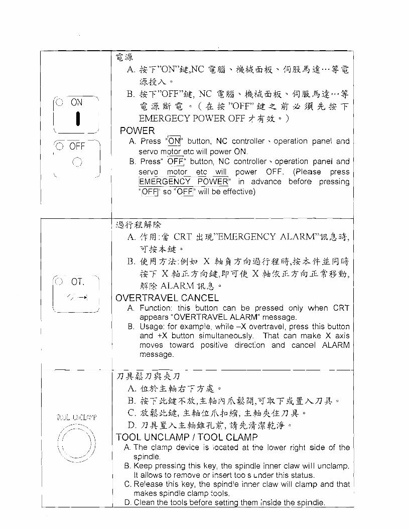
i$, A. j$7;"0N"&&,NC %#$ #&&&& {5JdBQ,'[email protected]$z
;%\&A
B, j$-F"OFFm&&, NC $$$&&& + J ~ ~ , ~ ~ - . * $ g $8, @ 0
POWER A. Press "ON" button, NC controller . operation panel and servo motor etc will power ON. B. Press "OFF" button, NC controller operation panel and servo motor etc will power OFF.
34733%P$? A. d+H :% CRT tf: l%"%j=j$Z ALARM"ffi,%fl+,T&.?+
&& B. 4EH $;k:i9ljh x $6J%4T$~fl+>4$&4+&Hfl+
.'L- 5' I$T X $ ~ L $ T % ~ & , F P T ~ ~ X $hi&L$6JZ $ $9%, 44 P* ALARM 3% ,%
OVERTRAVEL CANCEL A. Function: this button can be pressed only when CRT appears "OVER-TRAVEL ALARM" message. B. Usage: for example, while -X overtravel, press this button and +X button simultaneously. That can make X axis moves toward positive direction and cancel ALARM message.
TOOL LINCLAPIP D. & Z A & $ ~ ~ @ ? L $ , $%%;*?%&.$
TOOL UNCLAMP 1 TOOL CLAMP A. The clan-~p device is located at the lower right side of the
spindle. B. Keep pressing this key, the spindle inner claw will unclamp.
It allows to remove or insert tools under this status. C. Release this key, the spindle inner claw will clamp and that
makes spindle clamp tools. 1

A. Function: while executing the program which contains M08 or M09 commands, press this key and the coolant motor will run according to command instruction.
B. Usage condition: it is active only in "AUTO" mode. C. When this key is active, the built-in lamp will light up.
fa fiJ ;&I+ k A. ~hR"k:$F$&&%%%I+,tafiJ&&%~ O
B. ikfi 4$i+:& 6 %$&&&+%$&& +%%3k O
c. &$&&3kj&, FJ $&jgf$- & O
COOLANT OFF A. Function: No matter the machine is running or not, no
coolant flows out. B. Usage condition: it is active both in "AUTO" mode and
"MANUAL" mode. C. When this key is active, the built-in lamp w~l l light up.
#%+a f i d 8k A : $ , a O
B. i k m jl~i+:& Q ~ J $ A & & + ~ w + W ~ A c. &$&*3kj&, Iq&%g*% O
MANUAL COOLANT ON A. Function: No matter the machine is rur~ning or not, the
coolant keep flowing out continuously. B. Usage condition: it is active both in "AUTO" mode and
"MANUAL" mode. C. When this key is active, the built-in lamp will light up.
d ~ n c. %4+4g&Iz, ~ & $ , @ ~ & $ I J $ & # if{+& O
B. n&L$$:La+&j-*& O
n&l%$$:$a%&f*& O
TOOL MAGAZINE ROTATION A. Function: it is only active in "MANUAL" mode.
a. Press "MAN" key, as soon as the built-in indicating lamp lights up, this function will be activated. . -
b. Whenever press "CW" or "CCW once, tool disc will rotate to next tool.
c. If keep pressing this key, the tool disc will keep rotatina until this kev is released.

B. TOOL DlSC FORWARD: Clockwise (CW). TOOL DlSC REVERSE: Counter clockwise (CCW).
sh tlk : A. &"{$a "(FOR)$& ~9 &%2 %,{&a j!&iE-$$$,4+,-&&-
=k$k f i j%iE-$T w f d . , m &L a,& O
B. &"$jS"(BACK)$$m &%B%,.f#Zj $&iji#'Q754+,-Fj-&
-:k{+fi j$$iji$#j+h,+q &jg$ 0
CHIP CONVEYOR Function:
A. Press key, the built-in indicating lamp lights up, chip conveyor runs forward. Press this key again, chip conveyer will stop running forward and the built-in indicating lamp ex,tinguishes.
B. Press "m' key, the built-in indicating lamp lights up, chip conveyor runs backwards. Press .this key again, chip conveyer will stop reserve rotation and the built-in indicating lamp will extinguish
h?Gt!z At%4+ &#k<%flfi Descri~tion of Touch Panel

B. &#A,T$$k%47 CNC ~c~KP$!.*<$zA, AUTO MODE
A. It is also called Program Execution mode. B. The programs saved inside CNC memory can only be
executed under this mode.
ig !$i
F + ~ H ~ g ~ + + g ~ ~ ~ ~ + ~ g j ~ p ~ 3 i ~ m LINK It is used while using paper tape reader to read or using paper tape ~ u n c h e r to punch.
q $2 A. &&# A , T > T $pg%?g%k$,&~ fe$j +$z A, 7 $A&
47 O
B. &&$~A,T$,&A<K~ +@A,: a. FANUC % ylJr+g# g , . l S $ L e h 1 .IElqS&69$z
A, A t / b. 2% ,$ ?l]<+$$J %>R] $k&A$5$ $3&,&T--k
WP9h47 SINGLE BLOCK
D. It is able to input simple program to execute under this mode.
E. The simple program input in this mode: a. In case of FANUC controller, it is able to input single
block only. b. In case of MITSUBISHI controller, it is able to input
more blocks and to be executed in one time. a1 ~ f i
2 L /4 A. 12TSt&&&?%,B$4%/# t if l3~BqFjj+8% 5 $9@,5 $94~4xBEJ FfiM fig El fill M>Z%& O
B. 3t@ A,&~&#&g$q * ,&47&3k O
DOOR INTERLOCK A. As soon as this key is pressed, the indicating lamp will light
up and the door interlock will open for 5 seconds meanwhile. After 5 seconds, the door interlock switch will shut off automatically and the indicating amp will extinguish.
B. This mode will be inactive while the machine is running $zA,%;j$
A. 12~tt*ZZ %,$z&+3iFfi:kx 69 F(&E)-+& +&3k,&+&$5 9h I& ik TRAVERSE FEED Ffi#& %<I& *&+$
B. 1$3t$&j2 &,jFE&$-k%?~k% x%63@3,1$3t@&3k

DRY RUN A. As soon as this key is pressed, the indicating larnp will light
up and the F command in program will be inactive. Each axis will move at traverse feedrate.
6. Press down this key and the indicating lamp lights up. However this key will be inactive when the program executes tapping cycle.
C. Press down this key and the indicating lamp extinguishes, each axis will travel at the rate set bv F command.
&36&$7 O B. $$3t8&%&'&,Ep4kqi; ~ $ " / " ~ & ~ ~ % ~ ~ ~ ~ L ~ ~
BLOCK DELETE A. As soon as this key is pressed, the indicating lamp will light
up and the blocks which starts with "/" character will be ignored and the program will skip to next block.
B. Press down this key and the indicating lamp extinguishes, though the blocks starts with "I", it will not be skipped.
ig%j+k A. 4$3L&&E %,$L47+3 k,+ i; 9 g $j-"MOl"&-+: +,+z &
j+f+-L$?$&q @ ,g&$g,+& a+]$T"+g &,&&"&& Ep
k OPTIONAL STOP
A. Press down this key and the indicating lamp lights up. If the blocks in the executed program contains "M01" command, the said program will stop at the block contains MO?. If intend to go ahead, just press "CYCLE START key.
6. Press down this key and the indicating lamp extinguishes, though program contains "M01" command, "M01" will be ignored and the program will not be stopped.
$$&!I @ x A. $$3t;$&$g%,$kj7+tgjl; +,g$j- M.S.T. CODE 46 +T%
j 7 , i & $ k j ~ G CODE r 4 i + o B. 4G 3t&&$$f~&,+kij- G.M.S.T CODE 3: +Z $S.I+
M.S.T. CANCEL A. As soon as this key is pressed, the indicating larr~p will light
up. If the blocks contain M.S.T. commands, M.S.T. code will be ignored, only G code will be executed.
B. Press down this key and the indicating lamp extinguishes, the system will execute G code and M.S.T. code and operate normally.
&&$h x A. 1%3ti&$g%,$z&%47&3-%4%.1+83,4aE@R;f;4&L%
gJj*,4~&&43-#+++l.t7??& B. $$&47 G28.G29.G30 E+,&&&? @$3 3 $$&,P@ $A &p&
% ~ T B 4 g j ~ e~ $3 A,$: +,&+&B ,xb 69 $g % g.113 6 2-
52 C. M.S,T $u G $k+-@iE,@i&47, ~ + Q & # & $ ~ x f i j +
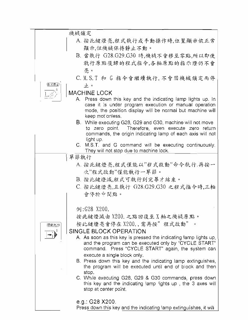
l.t MACHINE LOCK
A. Press down this key and the indicating lamp lights up. In case it is under program execution or manual operation mode, the position display will be normal but machine will keep motionless.
B. While executing G28, G29 and G30, machine will not move to zero point. Therefore, even execute zero return commands, the origin indicating lamp of each axis will not light up.
C. M.S.T. and G command will be executing continuously. They will not stop due to machine lock.
$6;
494 :G28 X200. i%&t6&-E;& ELI x200, *,%ti El 4 g 3 x $&*+A$&* ,%A O
4 x 2 0 0 , 4 " z k " O
SINGLE BLOCK OPERATION A. As soon as this key is pressed the indicating lamp lights up,
and the program can be executed only by "CYCLE START" command. Press "CYCLE START" again, the system can execute a single block only.
B. Press down this key and the indicating lamp extinguishes, the program will be executed until end of block and then stop.
C. Wh~le executing G28, G29 & G30 commands, press down this key and the indicating lamp lights I J ~ , the 3 axes will stop at center point.
e.g.: G28 X200. Press down this key and the indicating lamp extinguishes, it will

return from X200 to X machine origin point. Press down this key and the indica.ting lamp lights up, it will stop at X200. it needs to press "CYCLE START" again.
Description of Manual Operation ,--- Mar~r~a 1 c~pera: I cn 7
a % +B xfi a ~ + w + : f ~ a ~ Description of Manual Operation
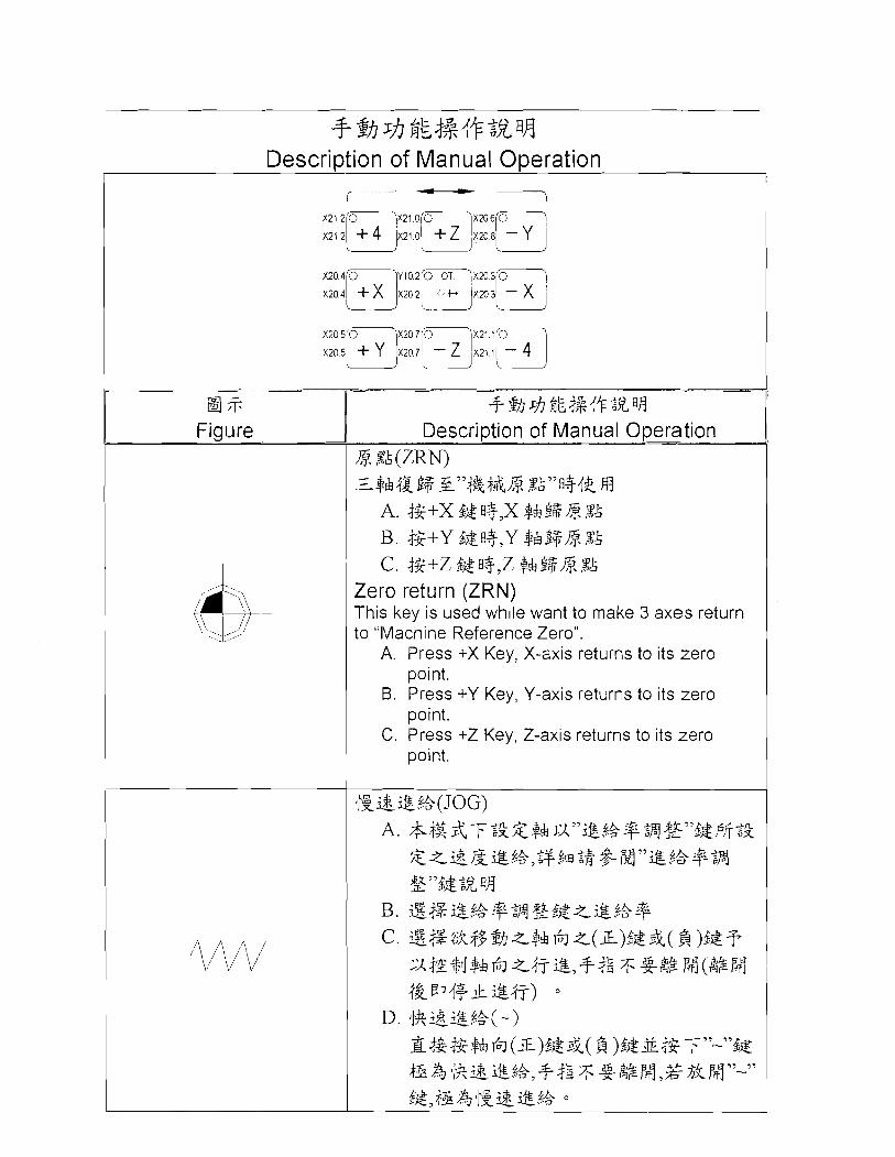
l$. %A (ZRN) g7'4~++m. ,x~~~u3jg m
C. j$+Z &&fl$,Z $&$$L$ %A Zero return (ZRN) This key is used while want to niake 3 axes return to "Machine Reference Zero".
A. Press +X Key, X-axis returns to its zero point.
B. Press +Y Key, Y-axis returns to its zero point.
C. Press +Z Key, Z-axis returns to its zero I point.
m
BO
u
9 PJ
-as
cS
w ;r
g;(D
&~
YM
%$
E&
&
+
-mz
cn
" -(D
E
?.-
ac
-$i$
i@4
?R
%iG
rn
a,m
$
Q-'
(D i
4
2-
a
~
>>
!+~
/$iQ
f s/
$i
-'o
m
" 2
0 0 j&
(%
+ *
* 4
4 '..
$2
Z(D
m-
ob
b- m
- w
ap
:o3
ll@
8;P
T/$
ihi;
%ik
+
52
.m 2
gm
o
pg
-q
p
p g
Z?
$y
",
m
v
A\ *
o;$
&v
$
7;$
'+"s
, +
\
m-
'v%
(D
(D
-'
(D
(D
C
0
4-
,% O
/$
ib
&$
a
5
"" )A&
s .;go
3-
%
2 .,o
$
fib
'D
"
so
2
0
4@z
&g
e
<
.qb
@
&
3 g
ap
2 nl
.- % 2.
E.
XI B:
a
(D_
" Q
"
4@Ei
k+
%%
$
$-
- S..
z. %
7!
-mm
-
2.
Z.
-
- O
il$
k
g
32
(D
z 1:
@&
- 3
Q
35
1:
Lm
5P +
,(D
2

C. When the above selection is completed, it is able to use hand wheel to control the axis movement.
D. For the details, please refer to the description of hand wheel operation.
c . , ' 6 %f& &" T o
D. $Z&?&$$%&, g w p 6 &@fi, & G &
a;T; $& $8 sh n"g 4% $X HFJ
r
&%?-#%&rzthI'F o
Edit A. It is able to edit, modify, add or delete the
original programs under this mode. B. -This function is only used for editing
program, not for executing program. C. If intend to execute new edited program, the
system should be under "AUTO" mode. D. As soon as the program editing is
completed, the computer will save program automatically. It is not necessary to execute saving action.
w*,;
Figure
Home Return Press this key under "Home Return" mode, Z axis will return Home first, then X, Y axis return to Home sequentially.
s- 4'F $@
A. 4$3t$&%$$f,s-.f+$@3l- P4=j O
Description of Edit Function
B. 4zbt$&$@j&,~4+$@Ei h7 O
Working Lan-lp A. Press th~is key and .the indicating lamp lights
up, the working lamp will turn ON. B. Press this key and the indicating lamp p
.i!& g

Fiaure
%.+ +j${+$% El4 Descri~tion of Feedrate Setti lia
A. Yoj@~,j+,** $ z & : 2 x & B ( F ) L 3 * tt; O
{p]k~:$gz& 120%,F300 &%
+&X&&@.++ a
A. When % indicating lamp lights up, that means feedrate % set by original program is active. e.g.: if set 120%) F300, that means the feed rate is 300*120% = 360mmlmin
B. When VIM indicating lamp light up, that stand for the feedrate per Minute. e.g.: if set at 6000, that means the feedrate is 6000rnnilmin
C. When the mode is set at "AUTO" or "MDI" mode, and the feed rate of GO1 is in act, it adopts % value to stand for its feed rate.
D. When the mode is set at "JOG" or "AUTO" mode and executes Dry Run, it adopts MM value to stand for its feedrate.
&&xi * tt; A. + A & @ . % & + & & 4 $Z(FO 25%
50% - lOO%)-"rlES% o
B. q-&jg$,,$.#&&q *tt; $kz& @@.el& 7+ 0
a. <fig$? Q $hf&&T& 0-200% o
b. $?+%I JOG &KT&, Q &I$&&T h!~" DRY RUN" s j ~ $ k , 25$243$fi$$
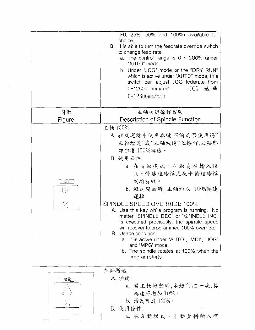
Feedrate Override in % A. There are 4 rauid traverse federate override
a* Figure
(FO, 25%, 50% and 100%) available for choice.
B. It is able to turn the feedrate override switch to change feed rate. a. The co~itrol range is 0 - 200% under
"AUTO" mode. b. Under "JOG" mode or the "DRY RLIN"
which is active under "AUTO" mode, this switch call adjust JOG federate from 0-1 2600 mmtmin. JOG & + 0-12600mm/min
&9&* n"k4+.l+ZjiVl Description of Spindle Function
&$& 100% A. $z&g% QIkH & ~ & , T Z & & % I ~ H 3''
&9&3g&"&"&$&;&&"z334+,&$&2p E p m 4 $ loo%#&
B. IkRl 4H+: a. & $)&A, -f%%$+$$hf&
& dp&i.&t&fg&&# $&i.&.t&f$ &3$%3k
b. $~&,#%83, 2$$135~:/1 loo%#& SY*
SPINDLE SPEED OVERRIDE 100% A. Use this key while program is running. No
matter "SPINDLE DEC" or "SPINDLE INC" is executed previously, the spindle speed will recover to programmed 100% override.
B. Usage condition: a. It is active under "AUTO", "MDI", "JOG"
and "MPG" mode. b. The spindle rotates at 100% when the
program starts.

& f$&i&%$&&X+ $k%.%$& &33%3i O
b. zfr$4&3Zfl3, &6&&3k, a 6 4gjF;;&<kXr S $-$a lOO%%%f
SPINDLE INC.
A. Function: a. Whenever press this key while
spindle is rotating, ,the rpm will be increased 1 0%.
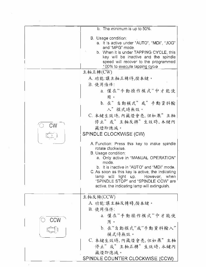
b. The maximum is up to 120%.
B. Usage condition: a. It is active under "AUTO", "MDI",
"JOG" and "MPG" mode. b. When it is under TAPPING CYCLE,
this key will be inactive and the spindle speed will recover to the programmed 100% to execute tapping cycle
% $& j&&
A. zJInLL: a. $ %$&$+% f l~y&$&~dG-=kyE
$.$L&j$j&$ 10% O
b. fk/J&T& 50% B. 4km +%4+:
a. & 6 + % $~$+$$AV& & ~t$&i&,%f&&X+ %i&.%f& &33$73i O
b. ~fr$4&3gfl+, &@&3k, a & 6 s?l a 4 g $ z & < k X r S $$& loo%% if
SPINDLE DEC.
A. Function: a. Whenever press this key while spindle is
rotating, the rpm w~ l l be decreased 10%.
b. The minimum is up to 50%.
B. Usage condition: a. It is active under "ALITO", "MDIJ1, "JOG"
and "MPG" mode. b. When it is under TAPPING CYCLE, this
key will be inactive and the spindle speed will recover to the programmed 100% to execute tapping cycle
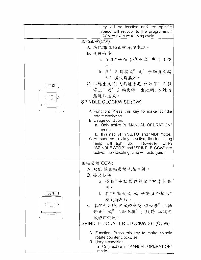
4-$$rZ%(CW) A. sh$&:~&&$&~%fl+,&&& B. 4kH &4+:
a. IS&" 3- %+$I+ f& & " + $ ikI% m
b. &" $ @y&&" &" +$bj$$+$,$ A" f&&fl%&$k o
c. &$&k$kfl+, fi&$E*%, 4 E 4 ~ %'' &$& ,+," 4'' &$&k$$" !L$kfl+, &$&fi &$gEp$&;& O
SPINDLE CLOCKWISE (CW)
A. Function: Press this key to make spindle rotate clockwise.
B. Usage condition: a. Only active in "MANUAL OPERATION"
mode. b. It is inactive in "AUTO" and "MDI" mode.
C. As soon as this key is active, the indicating lamp will light up. However, when "SPINDLE STOP" and "SPINDLE C C W are active, the indicating lamp will extinguish.
SPINDLE COUNTER CLOCKWISE (CCW)
A. Function: Press this key to make spindle rotate counter clockwise.
B. Usage condition: a. Only active in "MANUAL OPERA-I-ION" mode.
C. As soon as this key is active, the indicating lamp will light up. However, when "SPINDLE STOP" and "SPINDLE C W are active, the indicating lamp will extiqguisli.
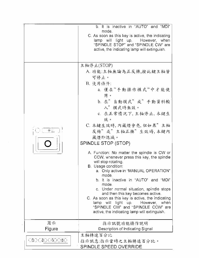
& $hi+ k(ST0P) A. Jhn"L:&$&&:k&iEk%7t$$t4&&$& k?
Ti+k O B. 4kfi 6 4 + :
a. i i t&"$-&3%.f+&&" Q 75 n"L.Ik m
b. &l ' a *,Jlfg&ll & l l $-!zhg++$& A'' fg&fl+%3k o
c. &iE%tg?%-F, & $ & i + k , *$&* 3k 0
c. *$&*3kfl+, lq&$g*%, &$& k$$" &" &$&iE$$" %3kfl*, ,&$gEpj,&;& O
SPINDLE STOP (STOP)
A. Function: No matter the spindle is CW or CCW, whenever press this key, the spindle will stop rotating.
B. Usage condition: a. Only active in "MANUAL OPERATION"
mode. b. It is inactive in "AUTO" and "MDI"
mode. c. Under normal situation, spindle stops
and then this key becomes active. C. As soon as this key is active, the indicating
lamp will light up. However, when "SPINDLE CW' and "SPINDLE CCW' are active, the indicating lamp will extinguish.
a % Figure
L
I
+k % % ~ ? k ~ h $L3+4+2Xvj Description of Indicating Signal
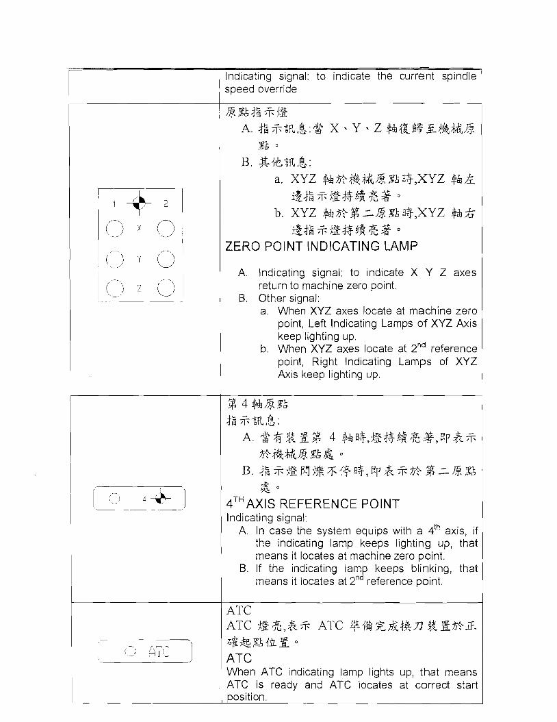
* ,%A$: * ig A. 4: *%fl,&:$$ X . Y . Z $d34jg9$?3i#&t&L$i
,%k B, g*:fl,f$:
a. XYZ +&$?;t.%&h,% ,Tk B ~ ~ X Y Z $&A &+g *jg++,@ & 3
b. XYZ $&$?%~L$i%kf l3~XYZ $&A &j: *jgj+,$ & 3 0
ZERO POINT INDICATING LAMP
A. lndicating signal: to indicate X Y Z axes return to machine zero point.
B. Other signal: a. When XYZ axes locate at machine zero
point, Left lndicating Larr~ps o f XYZ Axis keep lighting up.
b. When XYZ axes locate at 2" reference point, Right lndicating Lamps of XYZ Axis keep lighting up.
4 +&@\$k j g *:fl,&.:
A. * g g g % 4 $ & f l ~ , % ~ + + @ & ~ ~ ~ p j % % *;t.&t&& %k&
B. & %%gr~!j$64+fl$,Ep&%$? % :%,%& &
4 T H ~ ~ l ~ REFERENCE POINT lndicating signal:
A. In case the system equips with a 4'h axis, if the indicating lamp keeps lighting up, that means it locates at machine zero point.
B. If the indicating lam keeps blinking, that B means it locates at 2n reference point.
ATC ATC %B%>&% ATC +i&z&jgn $$g$?i~.
When ATC indicating lamp lights up, that means ATC is ready and ATC locates at correct start
osition.

NC%f$&,&;T; C N C j 2 - ; f ( % g # $ $ 5 J & q
NC When NC indicating lamp lights up, that means CNC controller has error alarm. ")%a$ z L,,
A, %+$:fi,$.:2,&J$h4&$?$pfq3 O
B. $gq%%fi,$.:
a. $k$.$%%%jS,-)4+
b. j&&&iE+A,%~$ZA0+&2fi,3 & 3A,#
,tf4,@$447%$&* $8 $z&,&$& ${+
lt o
AIR PRESSURE ABNORMAL
A. Alarm signal: air pressure is lower than standard value.
B. Other signal: a. Alarm lamp will activate. b. If this signal appears while machine is
executing a program, ,the niact-line will not stop until the block is completed.
+A hl] i-k 3$ $ i+% + A. -+- , .fi,$,:73($5 r)J f i Q + ~ g { * g g 4 & $ ? ; $
% M ai%2;3r73(4a B. $gj&;fi,&:
a. $$$.$%+$&&{+
b. 4&$&4?3fik$g,@$,-)4+
COOLANT ABNORMAL
A. Alarm signal: the coolant level inside the coolant tank is lower than the level set by float switch.
B. Other signal: a. Alarni larr~p will activate. b. Machine can keep operating.

" '&,@+g@" a, &@@& 0 c. i,
SPINDLE ABNORMAL
A. Alarm signal: spindle motor is abnormal. B. Other signal:
a. Alarm lamp will activate. b. Machine will stop while executing
program and change to "FEED HOLD" c. The built-in "FEED HOLD" indicating
lamp will light up.

\ / 79 ' 1 6 m STOP , 80 90
0 m,,- 1m
E 6.2-2(fl~F$&@i~rn&)
Fig 6.2-2 ouch Panel)
6.1-2 EMV860/1020/110011400 Wi$j @ &j #k$xaJj
3: ,$%4+k Rj fig A. EJfi??&+&+$k R,$jkix,i~d4nd&&%+$k$L%*h4+
T ~ L ~ B F ~ A ~ a+k&gw+im B. -
&$&$k$*$ O C. kn%kf#&fi t %,&4+kAk&, $$j+i$$~I&lll~~+$t;5r%
$k+$Ep ?J- O
EMERGENCY STOP A. Press this button in emergency situations, i.e. when human
life is in danger or there is a risk of damage to the machine or workpiece.
B. After pushing down this button, all machine movements, such as feed and spindle rotation will stop immediately.
C. f intend to release this emergency stop status, just turn this button clockwise.
'0 OT.
// +4 \ , - - -
]
% j@\
A. d$T"ON"$&,NC "gfig - +%;i:&&#& - {qAk,% & . . a ! $
;@\$%A O ;F ((C B. &T"OFF"$&, NC - +%;id&#& - 4qABB8%%-..%
8, @ a ( & d$ "OFF" $& < 3 $h 5j j % d$ T EMERGECY POWER OFF $ $f 5k )
POWER I l u A. Press "m button, NC controller . operation panel and
servo motor etc will power ON. B. PressJ1 m: button, NC controller - operation panel and
servo motor etc will power OFF. (Please press [EMERGENCY POWE@' in advance before pressing PO OFF^" so "IOFF" will be effective)
347+zA+ I$? A. 4% H : $ CRT $3RMEMERGENCY ALARM":%,$ a*,
-TdG&& O
B. 4km 3;k:i9q4~ x $dl g $l%*4~+~fl*,dG&4+&FJ fl* * 9 d2T X $hZ-$l%~&,WT4& X $h%iE-$l%iE- $.$P%,
;15+ P$? ALARM 2% ,$. OVER-TRAVEL CANCEL
A. Function: this button can be pressed only when CRT appears "OVERTRAVEL ALARM" message.
B. Usage: for example, while -X overtravel, press this button and +X button simultaneously. That can make X axis moves toward positive direction and cancel ALARM message.
n g $ g n g A n A. 4fL;fj?4.$h%-F$& O
B. d$TrtL$&TAk,4.$hfifi\$&p4Ej7T%T&zhng o
c. zk$!rtt$&, 2$h4fLfi\+~&%, 4.$h A4zn g O D, n g g ~ 4 . 9 h 4 f ~ ~ L 3 , $gifi;g;%$"t+ o
TOOL UNCLAMP /TOOL CLAMP A. The clamp device is located at the lower right side of the
spindle. 6. Keep pressing this key, the spindle inner claw will unclamp.
It allows to remove or insert tools under this status. C. Release this key, the spindle inner claw will clamp and that
makes spindle clamp tools. D. Clean the tools before setting them inside the spindle.
(0 AUTO 1
A. ~hR"k:;V;$3&$?'~ El @lf.&"T&.I/j O
B. &FB $%#:@&"El &f.&"Q $ & 3 i a
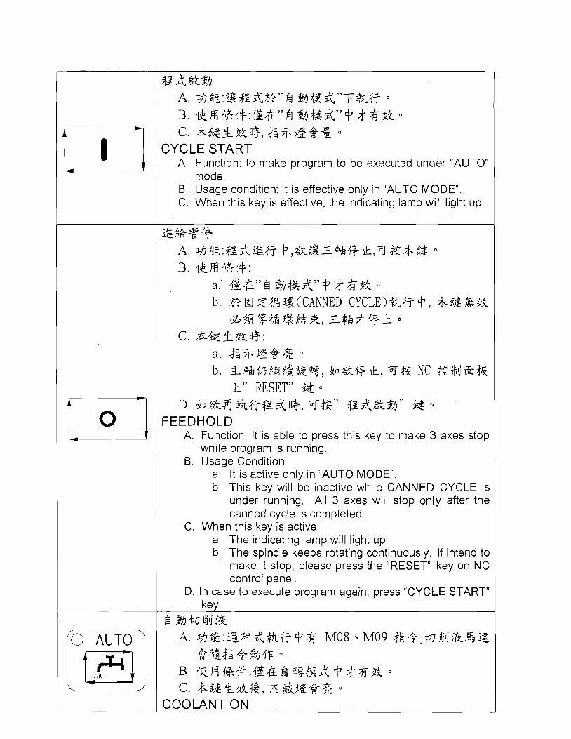
c. &4@&3ia+, 4: %%B$$2 CYCLE START
A. Function: to make program to be executed under "AUTO" mode.
B. Usage condition: it is effective only in "AUTO MODE". C. When this key is effective, the indicating lamp will light up.
?$,& q d+ A. ??$$k:$3&?$47 Q>%k%Z+&d+k,T42&& O
B. 4krB $R#: a.' @&"El %3'$&"9 $ & 3 i
b. $?HE4@Z(CANNED CYCLE)&4TQ, ;lfi6@&3i *5gS%&333%*, .Z$&$d+k O
c. &4&&3ifl+: a. #:%jg@% b. &+&4fi$E$$t~A$$, jf~&d+k, T42 NC 4%+i1G%i
1'' RESET" $& D. jflJ4k*%%~$Z & [+, T4Z" $3 &Zk&I" $& a
FEEDHOLD A. Function: It is able to press this key to make 3 axes stop
while program is running. 6 . Usage Condition:
a. It is active only in "AUTO MODE". b. This key will be inactive while CANNED CYCLE is
under running. All 3 axes will stop only after the canned cycle is completed.
C. When this key is active: a. The indicating lamp will light up. b. The spindle keeps rotating continuously. If intend to
make it stop, please press the "RESET" key on NC control panel.
D. In case to execute program again, press "CYCLE START" key.
El % +A 811 ik A. ~ h $ k : s $ ~ & % 4 j Q & M08 M09 4: +,tn%j1J?k~%3$
k A $?J'h.fa -t %.IT= B. 4kFB $%4+:dS& El $*&& Q $%3i O
c. &$@&3i$&, rn &%9*% a
COOLANT ON
A. Function: while executing the program which contains M08 or M09 commands, press this key and the coolant motor w~ l l run according to command instruction.
B. Usage condi,tion: it is active only in "AUTO" mode. C. When this key is active, the built-in lamp will light up.
MAN 'j
+- %,I +A' $11 ik A. ~ ~ h L : ~ ~ f ~ & & & ~ ~ 4 + , t A ' ~ ~ j $ k & , ~ $ $ ~ a
B. 4kH %45:& EI %f&d,&+-%f&A, Q%%PS; c. $$&!L$S;j&, @&%@*% a
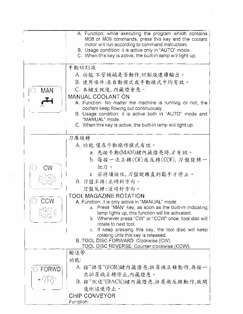
MANUAL COOLANT ON A. Function: No matter the machine is running or not, the
coolant keep flowing out continuously. B. Usage condition: it is active both in "AUTO" mode and
"MANUAL" mode. C. When this key is active, the built-in lamp will light up.
n&$g# A. 3Jjl$L:1S&$-3iI-#54+;f'&A,&5k O
a. kj$+-%(MAN)S&@&$2&fl+,$%Pk b. -@& - =kz#(Cw) & k$-$(Ccll), n %$fi$$ -
jcn c. %4+4jj4$42, ng$2&#gslj$3+$4+k O
B. n % ~ $ $ : ~ f l + 4 + % 6 J n$gk$$:igs+gt$6J
TOOL MAGAZINE ROTATION A. Function: it is only active in "MANUAL" mode.
a. Press "MAN" key, as soon as the built-in indicating lamp lights up, this function will be activated.
b. Whenever press " C W or "CCW' once, tool disc will rotate to next tool.
C. If keep pressing this key, the tool disc will keep rotating until this key is released.
B. TOOL DlSC FORWARD: Clockwise (CW). TOOL DlSC REVERSE: Counter clockwise (CCW).
$$i&p Jh hL :
A. 4$"4$fl"(FOR)$&?q &f@%,#Fa d&L$$%iI4+,%j2- zkjjlfi j$&L$$4+k,?q &fg,& O
B. j$"j$iig7y(BACK)$& f l &J@ %,-+$2 + & k # ~ h 4 + , 2 ' # j&1$4ig424+lk a
CHIP CONVEYOR Function:

A. Press "IFOR" key, the built-in indicating lamp lights up, chip -
conveyor runs forward. Press this key again, chip conveyer will stop running forward and the built-in indicating lamp extinguishes.
B. Press " F V , this key light up and chip auger act in reverse; release this key, chip auger stop.
Aq@ &-#%l+ &#rjifjiFl
Description of Touch Panel
8 $& & A. &$&$~&+h47$&& B. $ $k+h47 CNC ;LII~J?% Q r $ z A
AUTO MODE A. It is also called Program Execution mode. B. The programs saved inside CNC memory can only be
executed under this mode.
i$ .f:& tw + ?$d $ ~ 4 3 ~ & < ~ ~ & # 1 ~ $ & . ? i - 0 T . f ~ f i
LINK It is used while using paper tape reader to read or using paper tape ~uncher to ~ u n c h .
MDI +& g$+$$A
A. & * f g & ~ y ~ g ~ ~ $ ? ~ ~ k $ ~ ~ f a ~ +$z&? CA&
47 O
B. &*$g&-F$,&Ark9 +$z&: c. FANUC % ?l]r$2-;fid%,@$k&A 1 .fa%.%fi$$z
& o
d. 2 g $ ?l]*+!z-;fid % , f i l ] $k&A$5.5 $%&,&T-- -A A3 -A5 op&47
A. It is able to input simple program to execute under this mode.
B. The simple program input in this mode: a. In case of FANUC controller, it is able to input single
block only. b. In case of MlTSUBlSHl controller, it is able to input
more blocks and to be executed in one time.

\ ! l i DRN '1
D. $~&.4rk@$%&, qwp Q @@&, TljL.&gL$7f$&~@ 4'F
Edit A. It is able to edit, modify, add or delete the original programs
under this mode. 0. This function is only used for editing program, not for
executing program. C. If intend to execute new edited program, the system should
be under "AUTO" mode. D. As soon as the program editing is completed, the computer
will save program automatically. It is not necessary to execute saving action.
+z 3i 7.R ;% A. 4Gitt+&$g%,$~&j2F$ZkE6$ GO0,GOl 4; +&$k,&@
$9 5h 3 +/I& JOG TRAVERSE FEED F$45 z& +{a
B. ~ G & L & J $ $ ~ % , $ z & $ L ~ T J ~ ~ ~ - El Z ~ J $ J Z ~ % , ~ G & L & & & $ ~ c. 4G&t&&$g;&>&$&i&$z&:kxz F 47%
DRY RUN A. As soon as this key is pressed, the indicating lamp will light
up and the F corr~mand in program will be inactive. Each axis will move at traverse feedrate.
0. Press down this key and the indicating lamp lights up. However this key will be inactive when the program executes tapping cycle.
C. Press down this key and the indicating lamp extinguishes, each axis will travel at the rate set by F command.
%%T$ki;j 0
B. 4Gltt4&$g;&>Ep{g+i$ ~$f"/"4&g$,447Ts4l$g BLOCK DELETE
A. As soon as this key is pressed, the indicating lamp will light up and ,the blocks which starts with "/" character will be ignored and the program will skip to next block.
0. Press down this key and the indicating Ian-~p extinguishes, though the blocks starts with "/", it will not be skipped.

jii SBK 1
g$gj+Jh A. d ~ r t t w ~ % , I z ~ . I " ~ + z A ~ $5 9 gg7~o in ; t+z+ ,+~&;16
@Jhfi?$&+ $:,g&,$E,@ E I $ & T " + z & J ~ ~ & " & & E / J ~ 0
B. $Grtt@$Z~&,g+~&g"MO1"3z + E ~ , + z & ;h; 5 @ I + k 0 OPTIONAL STOP
A. Press down this key and the indicating lamp lights up. If the blocks in the executed program contains "M01" command, the said program will stop at the block contains M01. If intend to go ahead, just press "CYCLE START" key.
B. Press down this key and the indicating lamp extinguishes, though program contains "M01" command, "M01" will be ignored and the program will not be stopped.
y @ +h47 ",A A A. ~ G S ~ & & ~ @ % , + Z & I S ~ L L C A " + Z & ~ ~ B op ? r P J t 4 ? . & d ~ -
=k7'+Z&gkSfi"4S$L+A4T-% $5 0
B. ~ G L L L ~ & $ ~ ~ & , + Z & T & ~ T ~ I J Z$$?kj? 0 C. dGrtt&&$g %,X+k47 G28.G29.G30 <$z &3$ + fl3,=$&
@I+-$? Q /qlgtj&
l94 :G28 X200. dG&t+&%4t;&Eb x200, <,%A m4g3 x $&<$&&& ,%A G I x 2 0 0 d " k O
SINGLE BLOCK OPERATION A. As soon as this key is pressed the indicating lamp lights up,
and the program can be executed only by "CYCLE START" command. Press "CYCLE START" again, the system can execute a single block only.
B. Press down this key and the indicating lamp extinguishes, the program will be executed until end of block and then stop.
C. While executing G28, G29 & G30 commands, press down this key and the indicating lamp lights up , the 3 axes will stop at center point.
e.g.: G28 X200. Press down this key and the indicating lamp extinguishes, it will return from X200 to X machine origin point. Press down this key and the indicating larr~p lights up, it w~ l l stop at X200. it needs to press "CYCLE START" again.
Description of Manual Operation
-5 3% 99 ;jL-+%4+~jZflA Description of Manual Operation
l$ %A (ZRN) ~$h4~J2$3".3&4&l$ %A"fl+.l&fl A. j$+X $&@,X $hB$l$ %A B. j$+Y $&e+,Y $hP$J$?,XA c. jgtz $&s+,Z $h$gl$,%
Zero return (ZRN) This key is used wh~le want to make 3 axes return to "Machine Reference Zero".
A. Press +X Key, X-axis returns to its zero point.
B. Press +Y Key, Y-axis returns to its zero point.
C. Press +Z Key, Z-axis returns to its zero point.

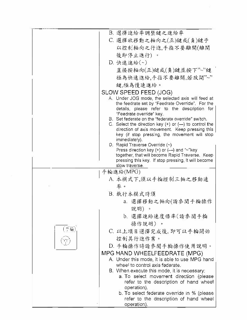
SLOW SPEED FEED (JOG) A. Under JOG mode, the selected axis will feed at
the feedrate set by "Feedrate Override". For the details, please refer to the description for "Feedrate override" key.
B. Set federate on the "federate override" switch. C. Select the direction key (+) or (-) to control the
direction of axis movement. Keep pressing this key (if stop pressing, the movement will stop immediately).
D. Rapid Traverse Override (-) Press direction key (+) or (-) and "-"key together, that will become Rapid Traverse. Keep pressing this key. If stop pressing, it will become slow traverse.
+ $kS%(MPG) A. +$&&T,$gc~+$ki2$4z$&<$$$h&
+ 0 B. $h47+$2&fl3$g
a. Sg$3%<$&67(2+&M+$&j%4+ 2.5A) 0
b. ggi&.%&&{g+(2+&iy+$k j%.I+$,flA) O
c. C A 4 J g El SsXF;fi$&, ? P ~ C A - ~ - $ & M %
i2Mg47*4+% O
D. + $ ~ ~ % . I + E I $ ~ + & M +~t!gj%i+.rrftrn ~ V A MPG HAND WHEELFEEDRATE (MPG)
A. Under this mode, it is able to use MPG hand wheel to control axis federate.
B. When execute this mode, it is necessary: a. To select movement direction (please
refer to the description of hand wheel operation).
b. To select federate override in O h (please refer to the description of hand wheel operation).
C. When the above selection is completed, it is able to use hand wheel to control the axis movement.
D. For the details, please refer to the description of hand wheel operation.

Figure Descrip1:ion of Edit Function I- 4+ f@
A. t%&t6&%%@,I-4+i@#~ H O
B. t$~t@%2;&,1-.I+i2fifl h'1 O
Working Lamp A. Press this key and the indicating lamp lights
up, the working lamp will turn ON. 6. Press this key and the indicating lamp
extinguishes, the working lamp will turn OFF. A. $+a&* JOG B!J&&,& i\J.I%&%@&
-Ln ; x k & & ( F ) Z X 2 t L o
{gdjp:$kx& 120%,F300 &%
41g4%&J%42E\e+ A. When O h indicating lamp lights up, that
means feedrate O h set by original program is active. e.g.: if set 120°h, F300, that means the feed rate is 300*120% = 360mmimin
6. When MM indicating lamp light up, that stand for ,the feedrate per Minute. e.g.: if set at 6000, that means ,the feedrate is 6000mmimin
C. When the mode is set at "AUTO" or "MDIJ1 mode, and the feed rate of GO1 is in act, it adopts % value to stand for its feed rate.
D. When the mode is set at "JOG" or "AUTO" mode and executes Dry Run, it adopts MM value to stand for its feedrate.

$? fi 3 , JOG $$ & T 8, 6 331 $$ A, T 69 '' DRY RUN" J~L$L, 2;$k433@&pk
A. There are 4 rapid traverse federate override (FO, 25%, 50% and 100%) available for choice.
B. It is able to turn the feedrate override switch to change feed rate.
&$& 100% A. +z&Gz++ wgm + ~ ~ 7 w ~ ~ m g m wY
&$&3~&'y&"&$$;&&77z4g4+7&$&%f ~ p m 4 X lOO%#$i O
B. 42m 4%44: a. & EI $!I$&& . fi9 g++$&h$&
& - j2&@,?$g&Efi$&@t&$& &33*3k O
b. +z&E+j*@, &$&39CA loo%++& g$!i$o
SPINDLE SPEED OVERRIDE 100% A. Use .this key wh~le program is running. No
niatter "SPINDLE DEC" or "SPINDLE INC" is executed previously, the spindle speed will recover to programmed 100% override.
B. Usage condition: a. It is active under "AUTO", "MDI", "JOG"
and "MPG" mode. b. The spindle rotates at 100% when the
program starts.

A. 5hjjL: a. $$ &$&#&I fl+,+$&-f+& -k,&
#&j$J$$flu 10% O b. fk&T& 120% O
B. 4 2 H 4%4+: a. & 6 ghfs & #&I %++$&A?&
jg&$,g?f&&&#+h$.g?fg &JiJ*3k O
b. ~k5f$h$3%fl+, +$&&$k, 2 8 %El 4EjFEA,'kE< S $$& loo%*%?- O
SPINDLE INC.
A. Function: a. Whenever press this key while spindle is
rotating, the rpm will be increased 10%. b. The maximum is up to 120%.
B. Usage condition: a. It is active under "AUTO", "MDI", "JOG"
and "MPG" mode. b. When it is under TAPPING CYCLE, this
key will be inactive and the spindle speed will recover to the programmed 100% to execute tapping cycle -
2 $s ;&I& A. ~ j 3 fik:
4% &$!&$.$a fl+,+$&4+@ - :k,g a. w
$-$&;i$;&p 10% O b. $2.I&T& 50% o
B. 4 2 H 4%4+: a. & 8 !&I&& # % W++$$A$$
& ~~gI&$,g?fg&&#&$,g?f$ &i$*& O
b. ~k%%fi3%fl3, +&&3k, 2& 2% El4$$~&'kE< S $*& 100%+k 47
SPINDLE DEC.
A. Function: a. Whenever press this key while spindle is
rotating, the rpm will be decreased 10%.
1 b. The minimum is up to 50%.
B. Usage condition: a. It is active under "AUTO", "MDI", "JOG"
and "NIPG" mode. b. When it is under TAPPING CYCLE, this
key will be inactive and the spindle speed will recover to the programmed 100% to execute tapping cycle
&$&Z#(CW) A. ? - - ~ L : $ $ & $ & Z # E + ) ~ G & $ & O
B. 4km +%4+: a. IS&"$- @I %.I+ f! Z't" + $ % 4 %
m o
b. &" ' &" $-9h2$+$$ A'' &&,fl+&$k o
c. *$&&$kfl+, i-q & j g @ % , ~E?PX'' &$&I 4+k" &,'l & $ & k # " & ; k q , *$&lq &jEEp$k.;& O
SPINDLE CLOCKWISE (CW)
A. Function: Press this key to make spindle rotate clockwise.
B. Usage condition: a. Only active in "MANUAL OPERA1-ION"
mode. b. It is inactive in "AUTO" and "MDI" mode.
C. As soon as this key is active, ,the indica,ting lamp will light up. However, when "SPINDLE STOP" and "SPINDLE CCW" are active, the indicating lamp will extinguish.
&$&k$$(CCW) A. ~j)6L::g&$&Ik+$fl+,jG&$& O
B. 4kH 6 4 + : a. I&E"$-$h4+f+t!&"+ $ $L4%
m o
b. &" @~;i:g&"&"$-B g $ t & h "
;i:gZ'tfl+&$k c. $&&&3k0+, i-q $&%E+j-&, 4 ~ 4 ~ X" &$&I
,+," &" &$&Z$$" *3kfl%, *&&El &$g Ep $,&.;& O
SPINDLE COUNTER CLOCKWISE (CCW)

[(I STOP 1
A. Function: Press this key to make spindle rotate counter clockwise.
B. Usage condition: a. Only active in "MANUAL OPERATION"
mode. b. It is inactive in "AUTO" and "MDI" mode.
C. As soon as this key is active, the indicating lamp will light up. However, when "SPINDLE STOP" and "SPIhIDLE CW" are active, the indicating lamp will extinguish.
% $4 {+ k. (STOP) A. ~h k k : % $ & & $ k & X k $ $ , i $ & L @ % $ &
W+k. O
B, 4kH a. {S&" # Sh f& A,'' % h L 4 2 H a
. & $ Sh&&" &" #%@$+.$$j
A" #A,fl+&;i O
c. &L$lg;xT, %$&i+-lL, &&k $;fr 0
c. &&&k;iu*, /q&jg@rZ, 4~4~s'' %$&I
k#" &" %$&L$$" k 5 k f l $ , &&&@I &jg lip$&.;& 0
SPINDLE STOP (STOP)
A. Function: No matter the spindle is CW or CCW, whenever press ,this key, the spindle will stop rotating.
B. Usage condition: a. Only active in "MANUAL OPERATION"
mode. b. It is inactive in "AUTO" and "MDI"
mode.. c. Under normal situation, spindle stops
and then this key becomes active. C. As soon as this key is active, the indicating
larr~p WII I light up. However, when "SPINDLE C W and "SPINDLE C C W are active, the indicating lamp will extinguish.

g ' K : s @ t t ; O 4; %:~,&:4$ $$ a + z ~ $ & $ ~ ~ SPINDLE SPEED OVERRIDE lndicating signal: to indicate the current spindle speed override * ,%& 4 i * $2
A. 4~ *$fl,&:$$ X . Y Z $&1EP$3+&hi* %& O
B. &&%R,&: a. XYZ $&$?).&&% ,%a+,XYZ
* 2- +C $4; *jgj+ig * 3 O
b. XYZ +&I$?% 2 % %A fl3,XYZ $&& 3 4 6 %$gj+k$. 3 2 O
ZERO POINT INDICATING LAMP
A. lndicating signal: to indicate X Y Z axes return to machine zero point.
B. Other signal: a. When XYZ axes locate at machine zero
point, Left lndicating Lamps of XYZ Axis keep lighting up.
b. When XYZ axes locate at 2" reference point, Right lndicating Lamps of XYZ Axis keep lighting up.
g 4 $&& ,%A 46 %:K,&:
A. $$ggg$% 4 $&a*,$gj+,$$%2$,Ep&% $?+&&l$ $A& O
B. 4 k * $ g r A 7 % % ~ d + ~ + , E p & * * g = % % A & o
4 T H ~ ~ l ~ REFERENCE POINT lndicating signal:
A. In case the system equips with a 4'h axis, if the indicating lamp keeps lighting up, that means it locates at machine zero point.
B. If the indicating lam keeps blinking, that B means it locates at 2" reference point.

ATC
ATC When ATC indicating larr~p lights up, that means ATC is ready and ATC locates at correct start position. NC NC kg&,&% CNC.@-$II%&4225&% NC When NC indicating lamp lights up, that means CNC controller has error alarm. &p z- 5 % 8
.A. 3&+33,&:2k@A4&3?4$+-g O
B. gj&<fL,!&:
a. ?i,,#$%+i$t$h4+ b. +&%iE$A,47$~& a+*<fL,g. Lh 3R,A%
jjg,@$A,47 z2gq '$ $2 &,+&+& 7f {+
k o AIR PRESSURE ABNORMAL
A. Alarm signal: air pressure is lower than standard va l~~e .
0. Other signal: a. Alarm lamp will activate. b. If this signal appears while machine is
executing a program, the machine will not stop until the block is completed.

a* Figure
% $4 $7 $L4%4+ 2% Description of Spindle Function
(0 APO 1
[J BLOW 1
'4. %+;fi,$.:;Iq ;$+A Jq b!J $4 ; # ; k s ~ 4 m ? ;$@M ni;kXr;&.Jstr o
B. g%2fi$: a. $k$$%+$@@4+ b. +&,#&4r5AL~E.%~4+
COOLANT ABNORMAL
A. Alarm signal: the coolant level inside the coolant tank is lower than the level set by float switch.
B. Other signal: a. Alarm lamp will activate. b. Machine can keep operating.
M30 6 $jl@s &3t&&$@ % Q ~ ~ $ ~ & & $ j - 3 M30 83,&&B!~.ic,& z;fi,M an @ Q @skati . @z,ltt$&$@i~; %Q%WI] &3i O
M30 Automatic Disconnection When this key light up and program is executed to "mp, the machine power supply will b e cut off. If this key doesn't light up, this function will not be effective. +A j$J .A
-h 42 3t$,&$@ % fl%,tA %jl] % M ,&d2- -A~+L&,,+,
%jl] .A ,% 88 Cutting Blow Off When this key light up, Cutting Blow off i s switched on; press this key one more time, the key light put out and Cutting Blow off is switched off. IwlJ ;+ PUMP &3t@$@%fl3,IB,lJ;Q PUMP M,&&--~kB$8,, 1811 :+ PUMP fifl Side Flush P u r ~ p When this key light up, Side Flush Pump is switch on; press one more time, the key light put out and Side Flush Pump is switch off.

+ % 2 $ & % 4 2 4Gfit;$&~@%fl3,I.$&.r~k;;:4a3h45,3G RESET $& T h q k 2 $ & % 4 2 O
Manual Spindle Position Press this key, spindle act in position; press "(RESEfl', spindle position function is closed.
%@&, FEED HOLD a3,i$fit;$&&$&@%$+,j$ iG 2$&Z.#6&&iG$~&, CYCLE START $&a+,
Spindle Pause When program is on "FEED HOLD", press this key so the spindle pause. Keep pressing spindle positive turning key or pressing "CYCLE START, spindle will automatically rotate, then 3 axes move.
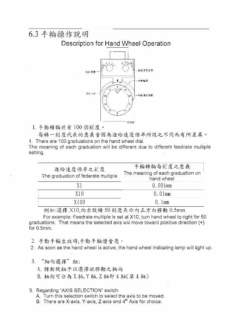
Description for Hand Wheel Operation
li11WS
1. #s,]$-$$;*& loo 4N2d & O
$j$-$-2d &{+,.&b$&$,@H 23@,%&&{%~~562k~5fi f i&PffZS 1. There are 100 graduations on the hand wheel dial. The meaning of each graduation will be different due to different feedrate multiple setting.
~ XI 0 ~ 0. Olmm ~
i!&t&i$.&{g+z2( & The graduation of federate multiple
~ XlOO ~ 0. lmm ~
LA +- #%#7ae2d&z&& The meaning of each graduation on
hand wheel
i?ib:B$f XlO,6JA3%$$ 50 2d &.&%6JL$6J$$&I 0.5inin For example: Feedrate multiple is set at X I 0, turn hand wheel to right for 50
graduations. That means the selected axis will move toward positive direction (+) for 0.5mm.
h.Zsc&S 2. +%I #$kk3ifl3,#%I #$ w a s 1 J L O
2. As soon as the hand wheel is active, the hand wheel indicating lamp will light up.
3. Regarding "AXIS SELECTION" switch: A. Turn this selection switch to select the axis to be moved. B. There are X-axis, Y-axis, Z-axis and 4th Axis for choice.

CHAPTER 7 COMMAND INTRPDUCTION ts A '* 7.1 M$a ? ia MCodeList
NOTE : 1. Fl+FANUC , M-+NIITSUBISHI , SI-+SIEMENS , F2+FAGOR
2.@+STANIDARD, %+OPTION, NA-+NONE
3 .Format:
M 3 W M CODE
0
dl 6k FUNCTION
$3 A43 k Program stop
1 Optional program stop
I Program end
I Spindle stop
&$& cw f$& ccw
ATC
Spindle CW
Spindle CCW
I Automatic tool change
7 8 9
2 $& CCW $%+A 811 ccw & coolant
10 Tool kit ON or water SF & 2 S & 4 7k(l) though % %
I C h p clean ON I % l % I % I % I
;Eb %A +?I 811 ;&(&I )
%jlJ &(@d)$& %(@a)
11
12
13
I Chip clean OFF l % I % i z I % I
Mist
Coolant on
Coolant off *mist OFF
n I 2 $& 4 7k( gd 1 %(fit)
2$& cw $%+A 811 & (l)
I Magazine right I N A I
O O Q Q Q O Q Q Q O Q Q
17 19
Tool kit OFF or water though ,,,dl, OFF Mist OFF
Spindle cw & coolant ON
- S~$Z&$%*
2$& m h
22
Q
@
End of subprogram N A
n&&
% % % %
0 @ ~ @ NA NA
NA
23
Magazine left
@ ' N A
n gl pot up
Q I O Spindle orientation
Q
0 1 0
O ' N A
1 0 N A

I I
25 n g ~ f z I TOO] clamp I Q i Q ! 0 N A I
M 3$+ M CODE
24
Tool unclamp Renishaw interface power 1 I ON , w N A I N A N A I
~h $k FUNCTION
n43-F 1 Pot down
Right tapping
F l M
I
28
Program end &rewind 0 0 I 0 I 0 I 4 th -axis clamp
S
0
%,%$&m(fii) Renishaw interface power 1 OFF
F2
NA
%
4.1 1 %a$&&&%& 1 4 th -axis unclamp
Chip conveyor ON
% % % %
42
Chip conveyor OFF
NA
B$$&4&3%gEJ
Wash downlChip clean I OFF
NA
48
49
Door open
NA
Axis index cycle start (cw % 0 % %
%Jk#8 %(@I) 5+lra25E(M)
Mirror image X OFF
Door close
Mirror image Y OFF
Screw auger OFF Wash downJChip clean ON
%
Search T-code tool no. ~ 1 1 ~ ~
%
%
64 67
1 71 %?&~#-x(!~EJ) 1 Mirror image X ON ~ % ~ % l % ~ % ~ I 72 % 4 & 4 g y ( M ) 1 Mirror image Y ON
.%
3 & 4 4 ( @ ) ATC fl;f. $Z & M EJ
.
.x
Mirror image 4 th OFF
Begin of ATC. Subroutine
.x %
% % % %

1 M CODE 1 ~h $L FUNCTION
F l M S F 2 i
MAG 2t % MAG 2 MAG.count/MAG. Ref..Search & t-table
t I I
I MAG: count1 MAG. Ref. search & t-table
Parts counter
I Sub program
1 100 1 ng$iwq$s.r+ 1 ATC arm 00-60'
I 110 I :tz&%n I ATC arm 1800 I N A I N A I N A I O I
7.2 G 3: + G Code List $L
FUNCTION i Z +%&
COMMAND FORMAT Goo 1R&$5$s3w
Rapid move command. GOOXYZ;
1 $%%+nI(iB+ Straight cutting command.
!I@ S% 6t 75- &J a 5.\ tn %jlJ
Clockwise round cutting.
.I$ $6' B8E3 , Time of stay.
GO1 X Y Z F ;
G17 G02XY R(1,J) F ; GI8 G02XZ R(1,K) F ;
Counterclockwise round cutting. G 1 8 GO3 X Z R(1,K) F ; G19 GO3 Y Z R(J,K) F ;
(35.1 A1 %%@$] A1 shape control.
G5.1 Q : Q l : N %&mbj$$4 & ON
A1 shape control mode ON
Q0:AI &@S*Jf& & OFF A1 shape control mode OFF

G 3: + G CODE
GO5 FUNCTION
64BIT RISC &/+$&$k@@ $II 64BIT RISC High precision shape control.
4$Z+pkz Mend value setting.
X.Y F & ge Surface choose.
Z.X & Surface choose.
Y.Z F & 3% Surface choose.
$4 & h Inch input.
&$]$$A Metric input.
Original home point check reference.
6 &J &*B ,%jK@ Auto refer to original home point.
& &*,%A& 9 $A g#: z%A From reference point through middle point to stop point.
% 2,3,4 @%A&@ # 2,3,4Go home.
n g+4%j$iE$j * Tool radius mend dismiss.
n S+4$&+$X Tool radius left mend.
ng+492+i$iE Tool radius right mend.
3: +$&A COMMAND FORMAT
G05P :
High precision shape control ON.
High precision shape control OFF. G6.2[P]K - - - X Z [R-l[F] -
UNRBS stage. X.Y .Z:@ $11 %'A Control point.
R: t t 2 Ratio
K: .$,% I$ 2 Terminal vector. F: @,%& & Feed speed.
G I O P R ; P: $4 iE Mend number.
R: 46 iE Mend amount.

~h ilk FUNCTION
A'g+43x3kJ%&E- Tool radius positive mend.
A'sW!M 3kJ+Fix Tool length negative mend.
A'ggg+Fix$$& Tool length mend dismiss.
Awl=&+?$% 1. Work coordinate 1. A U L , & + ~ + 2. Work coordinate 2.
Awl=B+?$ $. 3. Work coordinate 3.
hol=&+?$ 4. Work coordinate 4.
AWL&+% % 5. Work coordinate 5.
AWL& +% % 6. Work coordinate 6.
v$ @*TL4% 3%
Peck feed drilling circle.
k3 l%~ 'X%4%3% Reverse tapping circle.
~BTL+fl3lf 4% 3%
Precision boring circle.
a x4)& 3% S$j & Circle dismiss.
*TL4)&3% Drilling circle.
@TL4)& 3%(Z ,% %@) Drilling circle.(Point Z pause)
COMMAND FORMAT
G 7 3 X Y Z R Q F ; R:R $!i R Point
Q:-@:k@A' 3 Feeding volume.
F: @,%& Feeding rate.
G 7 4 X Y Z R F ;
G 7 6 X Y Z Q F ; R:R ,% R Point
Q: A' R.l& $9 3 Tool deviating volum
F: @.%& $ Feeding rate.
G 8 2 X Y Z R P F ; R:R %!i R Point
P:TL.flr31] &4+- gj s$B4 Hole position reached stay time.
F: @,*a $ Feeding rate.

G ti+ G CODE
~h 6k FUNCTION
tW&& COMMAND FORMAT
v4; %@ TL46 3% Peck feed drilling circle.
zk 3 46 3% Tapping circle.
e T L 4 6 3% Boring circle.
%TL463%(Z $dl &$dl4+k) Boring circle.(Z Axis spindle stop)
%TL.49f#TLtn f i l l 46 3% Boring and reverse cutting circle.
Boring circle. (Manual tool withdrawal)
eTL46 3E(Z #% %4$) Boring circle. (Point 2 pause)
Absolute value command. j&=@+g a 3z 9 Increase value command. $g$$ $$'&$kZ Absolute zero point setting.
Back to start point fixed circle.
G 8 3 X Y Z Q R F ; R:R $'A R Point
/- -A Q:e-A $77 9 Feed volume.
F: %,%& + Feeding rate.
G85XYZRF;(@4$3j-&@G84 +a Jq,4~%&$dl3A&fl?T@,$~& k%) (Same motion as G84, but spindle reached hole button is not change, and program reverse.) G 8 6 X Y Z R F ; R:R ,% R Point
Q: f l g.I& $5 3 Tool deviating volume.
F: @.&& + Feeding rate.
G 8 7 X Y Z R Q F ; R:R $A R Point
Q: f l g.I& $5 Tool deviating volume.
F: %.%& + Feeding rate.
G 8 8 X Y Z R P F ; R:R ,% R Point
p:TL4fi31J &I+ % BE7
Hole position reached stay time. F: %,%& + Feeding rate.
G 8 9 X Y Z R P F ; R:R ,% R Point
P: TL.Ifi 311 &I+= g BE7
Hole position reached stay time. F: $,%&* Feeding rate.

I G CODE 1 FUNCTION 1 COMMAND FORMAT 1 G99 R , % & $ ~ W ~ & $ ~ ~
Back to R point fixed circle.
CHEAPER 8 ALARM DESCRIPTION AND SOLUTION
Preface
This chapter--Alarm Description and Solution--can be applied to all EQUIPTOP machines which are equipped with Mitsubishi con.troller. We do hope that this explanation of trouble shooting can be helpful for you to repair the mechanical trouble so as to make machine resume normal operation.
g* Caution!
When check or test the electrical circuit under power ON status, it is necessary to be very careful. Implement check and test after the safety appliances have already been set up. Before attempting to do any modification and correction, please make sure that the master power switch has already been switched OFF.
After the master switch is cut off, please be care f~~ l that there still has remaining voltage left in the power supply. Please wait at least 3 minutes and then it is able to start modification and correction operation.
Content of Trouble Shooting

The main purpose of this chapter is to help you to confirm the cause of problem, and teach you how to use the information provided by 'this manual, so as to assist you to repair the mechanical trouble and make machine restore normal operation condition. There are some useful information you may need to know in foreword. Furthermore, it tells you that when you request EQUIPTOP technical services, what information you should provide to our service department. The correct information can help us to know the machine historical records fast and help us to decide the trouble shooting solution easily and quickly. Moreover, the exact information will be much helpful for our service engineers to find out the solutions earlier.
The operator may refer to the Operation Status Table to understand and notice the operation status. This table contains the discussion on the causes of problems, and the suggestion on the rectification procedures.
The flow chart "Error Judgment I Procedure Confirmation" is the primary guidance for problem solution. Execute test and inspection according to the flow chart. To make sure if the messages which appear during the procedure are the same as the graphic figures on this flow chart is always the best basis for machine repair. Sometimes the problems can be solved in the course of test procedure. Sometimes this flow chart can be helpful to find out some parts need to be replaced. Sometimes you request us for technical supports and the problems can be solved through telephone conversation.

You'd better record the "Error Message" appears on the screen during operation process. That will be much helpful to solve the problems fast, and on the other hand, it will help you to communicate with our service engineer easily and to solve the problem quickly.
Suggestion: 1. ~ g $ g g fij$d+=$-,qg4g~g++, fii$?;t.%%+4~@4+$.rB88%R%
i$Jx,&, &47;p~]$&4&4LI Rg&T $*&48 g i$J 2 a , +$, g*4tR
~ ~ * & B n j ~ ~ 9 g i E * El O
Check the information provided by operator, such as the : qchine motions and the messages displayed or. the screen. nner exec-~ii.;cj test and ir-zpedioii, i i these are not the principal fzctor to cause the problem, it is necessary to research th2 exact cause again.
2. 4%I$DI-%$7&4i j$ lk3#&&+;%($&, F?JU~+&F$~~F&, % T 4
Usually, yc I should sta :rouble shooting by chd~'ting and testing ope.-ation proced - 2 , Do not request to disassen;?'e machine pets just in the t- ;inning.
Deal with the problem o: by one. While executing troubl~ shooting, it is necessar- 3 take cause a i d result unde considere rl'2n simultaneou~
Attention
Deterrr~ine the ( 3ct cause whil: eakdown occ otherwise the same error will ( ,r repeatedly. . ~lutely, every jkdown has it:

own cause. Even a small sirr~ple part is worn-out, that may cause some other parts broken and lead the system malfunction and stop.
This machine is the complex combination of computer electronic engineering and mechar~ical engineering. Please contact with our service department for service, unless you are a well-trained and qualified electronic control engineer.
dX$%d+&*8 &%#Ffi$ rQ7 :
The operator itself is to collect the truth of problem:
%-Fpfi$$llg, sz& ~ ~ j & * q X 4 + & $ g%j&;g, JxR!$qJx~g$g 4&48'3Pfi%vsib!JZ$% O
Write down all matters. That can help you to avoid confusing the information collected and help you to make sure their difference as well.
*@t~b!~+usS$P+& s&.fikd-ff$ o
Be sure that you know what 'the machine is doing well.
*$&% $, iR&$:~,$!-4+@ O
What message appears on the display?
*plS: ? irtt$ & k g % X$ g4&jk.;Ftj$& O
Besides present problem, is there any other situation happens?
*ikP$j&& $1 %$&$&!-5 4- &4&*1t3&$&d+ O
Before the breakdown occurs, is there any other strange motion?
*rQ72gj$&<%-511$& 8 f?'J&4+A4q- O
What is the motion right before the breakdown happened?

Complete l nvestigation
Before calling us, you can execute detection and fulfill tliorough inspection according to all instn~ctions. That may avoid repeated work and avoid wasting time for telephone communication. For example: take the error message appears on the screen and user's explanation under consideration. That can narrow the detection range and make the probleni to be settled easily.
Confirm the breakdown situation
Record .the situation while breakdown occurs
NC S#$& &&4q?
Under which NC operation mode?
$ $jg#$&&fl*: @;i3kkP*@!k ~+z$Z&.th?&$Z&$3kx$Z& Fl %&{q?
In the case of AUTO mode: confirm the program name, program number and program content while the breakdown occurs.
In tlie case of MANUAL mode: remember the system is under which manual operation mode and remember the operation procedure.
2. $4 fl@$kz$$g;$@&&, A+'gE+&&zmg;+$EJ:2$& O
Write down detailed information showed on alarm diagnosis screen.
i & A g g < $ @ S &z$.s: The procedure to enter into alarm diagnosis screen:

(1) t%-F+&$kig%&r" DIAGN" o
Press function selec1:ion key "DIAGN".
(2 ) &-Fg$ -F$gFg%<" p g " , gg$$g!fs$jj@gfi - *&&g<fl,3& O
There is a menu selection in the bottom of screen. Press "ALARM" and the alarm screen will show alarm message.
35 w 3. @E;~$%g%:fl,;kxa sT$s*Jir4+&, @2%a4%%AkP*x%&3R7 -++ 0 J* k!4 &a
Y y r ...a &,.18'3 69 -HI%& A R o
Be sure to record alarm signal and content and startup the system again. Please pay attention whether the same breakdown occurs again or not. If yes, please contact with our service department.
Verify the written data for the machine you operated currently, such as:
*MODEL : $&& 2 3k MODEL No.
*SERIAL NO:+%&%3k
Serial No.
* * & b z x $ + T ~ ~ & ? $ , & $ $ a+&fk&%@& & g,+$&&k&$Q 0 =z E
You can see the above information on name plate or accuracy table.JW
Execute Inspection 4 ~ R ! ~ ~ ~ ~ ~ $ g $ ~ 1 \ i ~ b ~ z $ g b q , $ $ j $ . i & j ~ $ f i & @ j - g . ~ $ ~ @ f i
+ A N*3. $2Sjv%%i fi L, &R@Tp&~g*&j&?$,&&zj3# 0
In case you are a well-trained engineer, please remember to take correct safety appliances. to protect yourself while you are checking. Please remen-~ber not to destroy circuit and electronic parts.

In case you were not well-trained, please call our service department and tell us model number, serial number and the sign of the problem.
Check up the results
Please call our service engineer to discuss what you found out. Our service engineer will check and verify your procedure again. They will carry out a further check and point out some matters which are not evident but you need to know.
We would remind you again that it is necessary to provide detailed information to our service engineer. Besides machine model number and machine serial number, please also prepare electrical manual and parameter table, so our service engineer can provide the most assistance to you in short tinie.
Be sure that you know the error message. There are over one hundred error messages saved in Mitsu bishi controller software. Some messages are quite sirrrilar, but possibly refer to different machine parts. In order not to make any mistake, please write down the messages showed in the screen exactly.
To understand the sign of problem. The more you understand machine problems, the quicker to solve the problems. You and our service engineer can find out the better solul:ions easily.

To understand when did the problems occur. For example: whether this sign refers to a specific block in the program or refers to the specific tools used? Whether the problem occurred after a specific operation or occurred in the specific period of a day? Such information is useful for us to discover why the problem occurred.
*$t%&+k? % LED N@&, %ME%#kN LED $R%fi#k&kF+$4kfW~ e. e&g&fiikf*#i,$&, ;Z& LED H.iE@%,$, ~~,$%%iikF$$4k&NiJ%#~ lb 7
Check the LED on circuit board and understand the meaning of LED sign. Some LED on circuit board can provide usefl-11 messages for trouble shooting. When the machine is out of order, please pay attention to LED sign in order to shorten the trouble shooting process.
Machine Operation -0 LA ik &&kf*t4kF+*+Z +, !gq$iLi?@J g ,g 7j?&4+kk;x, &$&s $3 *i&.h,
3%.1+2jpq-~x&3z5$3g €I , .1zljgq-$iLg,g-$fi$g, ?j-#gg$$, gj &+&,{iq a+ i;t: awl B
In the process of trouble shooting, you may probably meet urgent status and you need to execute emergency stop, or maybe you get the machine diagnosis notice that helps operator to solve these niatters. However, you may need some more introducl:ions in order to facilitate you to solve the problem with our service engineer.
Emergency Stop
In the case of emergency situation, it is able to press down .the EMERGENCY STOP BUTTON (the red mushroom button) to turn off all servo power supply. The~screen will show emergency stop message.

The function to release emergency stop:
If the emergency stop button is pressed down, just turn and pull the emergency stop button, the servo power supply will recover a~~tomatically and become standby status in order to execute next process.
There are many error messages refer to machine diagnosis. This part of machine operation system will display the sensed and detected situations, so you can distinguish whether the problem still exist or has
already been solved.
The position of key corr~ponents and the RESET button
! G T ~ A ~ X % ~ + V I 4~ EJ & &,&$La A$,?~ffFf%4%,$€l Ei BnlZfjg qf7$€l 2+4&Z, ~%iJfiBQI%f73$~X&&*d
You may find out the position of the components, which are involved in the related problems, from the parts list, wiring diagram and manual. That will be helpful to solve problems.
& g&~T$A&%iJ l / k& i j ! j &%s&A%<%x,&, - 4 E p fi4'Ff73wwL,$,T & 9 Z&(RESET) S$ &
RESET BUTTON can be used to eliminate error and error message quickly. The error message from general operation can be eliminated by RESET button.

Malfunction Analysis and Trouble-Shooting (environmental factor)
jkXAX,&
Status and Message
El*#$ Cause Analysis
s E % p %
Rectification Procedure
Machine level is he ground bolt is not set bdjust the ground bolt again and variable roperly fix the nut after the adjustment.
eveling block is more than 2 eplace leveling block and do ieces. exceed 2 pieces.
he floor ground is not ebuild ground or execute soil enough. again.
1 %b bhere is too much steam install a compressed air filter. 1 The water cup of
I F.R.L com bination unit drains water frequently. I nstall a compressed air dryer.
ilter unit or dryer is blocked yLk~jgjgg~+k~~ r the drainage is not well.
epair or replace the dryer. t
fiuA2,&@+k& qeplace a air compressor with arger capability.
1. #&@i&f&%$a Check up the filter unit
+ clV- .& H,E%ic 5 q u& 2 ,&E!q%&i&@jaE,I&* .r+ d% 1 KG/CM +$ Air pressure is not enough and that cause machine stops frequently
ir pressure of compressed air source is lower than 6KG/CM2.
*j&%$a&&%j&!aZ& 3&7J(76 i%
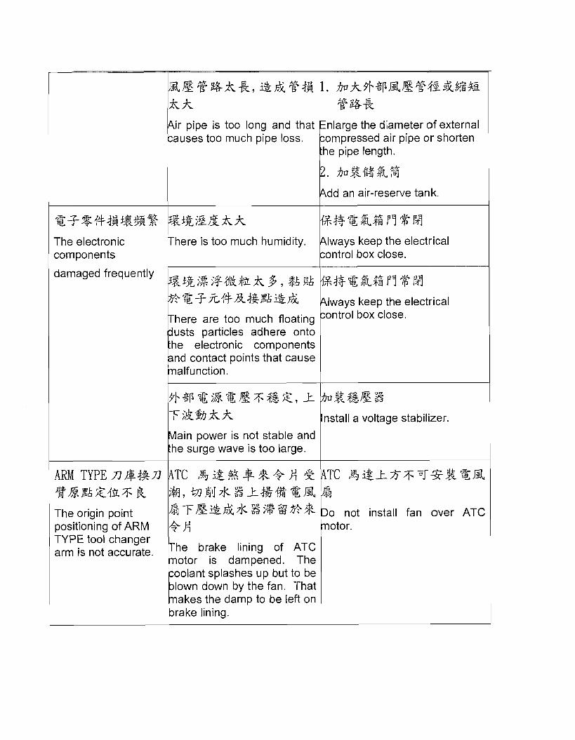
nlarge the diameter of external air pipe or shorten
dd an air-reserve tank.
The electronic components T here is too much humidity. lways keep the electrical
box close.
: 3 +A'f+x.fgS Iways keep the electrical
here are too much floating box close.
usts particles adhere onto he electronic components F
damaged frequently
nd contact points that cause alfunction.
a voltage stabilizer.
ain power is not stable and
* -.g ~ E ~ ~ i ~ f + e k $ i ~ A g , $ & ~ k
ARM T Y P E n @ # & n %&,%&fhsj;k The origin point positioning of ARM
{s#+?g,%.$grq$hq
TYPE tool changer arm is not accurate. he brake lining of ATC
otor is dampened. The oolant splashes up but to be lown down by the fan. That akes the damp to be left on rake lining. 6
TC l%ig+-Ssj;'T*$ZU3L
o not install fan over ATC
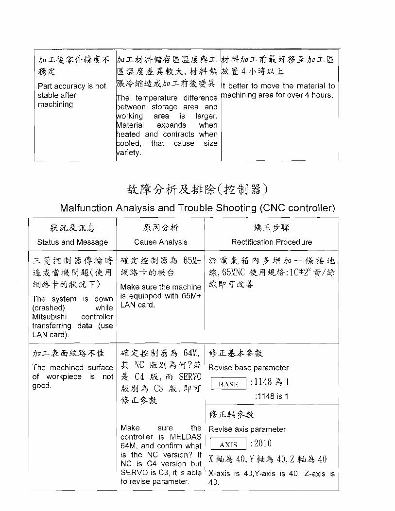
Part accuracy is not *c;+,(q%&Ijkh~r~j&@g stable after he temperature difference machining etween storage area and
, , I r k i n g aterial area expands is larger. when
eated and contracts when ooled, that cause size ariety.
i better to move the material to nachining area for over 4 hours.
Malfunction Analysis and Trouble Shooting (CNC controller)
& iX&% ,$.
Status and Message
%El*+$ Cause Analysis
%L*.%
Rectification Procedure
2- zt!z %i 8 i$% fl3 &&.g #& i an1 %(I% H ~ E I ~ + ~ ~ ~ x - F ) The system is down (crashed) while Mitsubishi controller transferring data (use LAN card).
The machined s~~r face of workpiece is not good.
@ZE%j%& 65Mt m%+ H#% 5 Make sure the machine is equipped with 65M+ LAN card.
@%%M%& 64M, g NC EBJ &~q?% 2 C 4 E, fi SERVO EXIJA C3 E, E p T {&a &$i
Make sure the controller is MELDAS 64M, and confirm what is the NC version? If NC is C4 version but SERVO is C3, it is able to revise parameter.
Revise base parameter
Revise axis parameter
:2010
X-axis is 40,Y-axis is 40, Z-axis is 40.
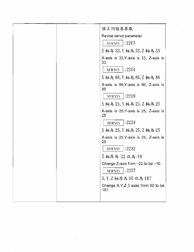
Revise servo parameter
X-axis is 33,Y-axis is 33, Z-axis is 33
X-axis is 86,Y-axis is 86, Z-axis is 86
:2219
X-axis is 25,Y-axis is 25, Z-axis is 25
X-axis is 25,Y-axis is 25, Z-axis is 25
: 2232
Change Z-axis from -22 to be -1 0.
: 2257
Change X,Y,Z 3 axes from 60 to be 187.

f i o ~ & & j - : ( PROCESS I
Wrong parameter causes malfunction.
@$&&&&%%$E Mae sure if the parameter setting is wrong or not.
Process parameter:
8004:SPEED A 100 8004: SPEED is 100
8005:ZONE r & 0 8005: ZONE r is 0
8006 :ZONE d & 0 8006: ZONE d is 0
8007:OVERRIDE 25 8007: OVERRIDE is 25
8008:MAX ANGLE 135 8008: MAX ANGLE is 135
8009:DCC ZOON & 10 8009: DCC ZOON is 10
8012:G73 n & 0.1 801 2: G73 n is 0.1
8013:G83 n 1 8013: G83 n is 1
8019:R COMP 99 zL& 60 8019: R COMP, change it from 99 to be 60.
8020:DCC. ANDLE & a 0 Zk& 10 8020: DCC.ANGLE, change it from 0 to be 10.
@z&*&& Revise basic parameter
11139
@ & 4 z k & l Change it from 4 to 1

n $f A, ATC e3kn ~ $ z + R % + n , & ;kz&+%n%4+ Arm type ATC got stuck in the process of tool changing, so that it can not fulfill tool change motion completely.
T H 3&+3?&4&;5&
Does not take mechanical method, such as rock handle for trouble shooting.
A. BE MPG f$&3%4+A$&4&$$Ef AIL t-4 S $ i s x , t 6403. 0 2;. 1
Set machine diagnosis parameter 6403.0 to be 1 under MPG operation mode.
Use Cycle Start Button , which is located on control panel (green) to execute manual jog to make tool arm rotate CW(clockwise)
C. $z&i$-k($~&)T+ %--j'-&4%73 CCW k#& .I+ (6Btkn H * i m n $4 a=FJ )
Program stop (red) can execute manual jog to make tool arm rotate CCW (It is active during the period tool change start to tool unclamp complete).
Spindle will determine tool clamp/unclamp automatically.
F. Tool magazine will not disorder. It needs not to reorganize the tool magazine.
G. jg +i$l&@, &%Z.g$&T9fi $$ HOME ,%, EpT3%4+
If power OFF halfway, it is not necessary to execute Home return and able to continue operation
H. $4 #i PLC $ g stt 53 ;3'L Only new version PLC is furnished with this function.

=€it3 =J-g Option
n w EI BBW Automatic tool measurement
1. $ 1 NO 1 500 Set the distance betwen workpiece and probing instrument NO 500 @@ Path
NO 1 500 1 XXX XXX
- =n-+!Jn EJEEXEGT Height probing instrument
Workpiece is lower than
-wzn+- ~ . G ~ ~ ~ E T1 RgqAfi TIM6 M76 1 BP$a$gg H1
Only execute TIM6 1 M76 T1 can be set and automatically set H1 TIM6 J M76 J
T2M6 ; M76 ; T3M6 ; M76 ;

Drawings of re-setup for each axis returning to origin point. Please re-operate controller according to the position shown on the drawings.
X-AXIS