manual on the use of timber in coastal and river engineering · publishing director, thomas telford...
TRANSCRIPT

Manual on the use of timber incoastal and river engineering
Matt CrossmanJonathan Simm

Published by Thomas Telford Publishing, Thomas Telford Ltd, 1 Heron Quay, London E14 4JD.
URL: http://www.thomastelford.com
Distributors for Thomas Telford books areUSA: ASCE Press, 1801 Alexander Bell Drive, Reston, VA 20191-4400, USAJapan: Maruzen Co. Ltd, Book Department, 3–10 Nihonbashi 2-chome, Chuo-ku, Tokyo 103Australia: DA Books and Journals, 648 Whitehorse Road, Mitcham 3132, Victoria
First published 2004
Cover photographPile extensions (courtesy Arun District Council)
A catalogue record for this book is available from the British Library
ISBN: 0 7277 3283 8
© Queen’s Printer and Controller of Her Majesty’s Stationery Office and HR Wallingford Ltd, 2004.
This work is not subject to the terms of the Class Licence for the reproduction of Crown copyright material.
All rights, including translation, reserved. Except as permitted by the Copyright, Designs and Patents Act 1988,no part of this publication may be reproduced, stored in a retrieval system or transmitted in any form or by anymeans, electronic, mechanical, photocopying or otherwise, without the prior written permission of thePublishing Director, Thomas Telford Publishing, Thomas Telford Ltd, 1 Heron Quay, London E14 4JD.
This book is published on the understanding that the authors are solely responsible for the statements made andopinions expressed in it and that its publication does not necessarily imply that such statements and/or opinionsare or reflect the views or opinions of the publishers. While every effort has been made to ensure that thestatements made and the opinions expressed in this publication provide a safe and accurate guide, no liability orresponsibility can be accepted in this respect by the authors or publishers.
Typeset by HR Wallingford LtdPrinted and bound in Great Britain by MPG Books, Bodmin, Cornwall
This report also constitutes the joint Defra/Environment Agency Flood & Coastal Erosion Risk ManagementResearch & Development Programme Publication W5A – 069.
iii
Preface
This document is intended to provide information and guidance on the use of timber incoastal, maritime and river engineering projects.
Timber has traditionally been used for the construction of a wide variety of engineeringstructures in or near water including groynes, jetties, lock gates and river bank protection.The fact that it is still used for many of these applications, despite advances in alternativematerials is, at least partially, a reflection of the generally accepted characteristics that maketimber an attractive choice of construction material. These are:
renewable resourcehigh strength to weight ratiohigh tolerance of impact and short duration loadsgood resistance to abrasionease of construction, on site repairs and recyclingattractive appearancenatural durability (to a greater or lesser extent).
However, there are also a number of potential drawbacks including:
inherent flaws and variability in properties associated with all natural materialslimited availability of the very large section sizes, long lengths or high durabilityrequired for some engineering purposesspecies of timber native to the UK are only moderately resistant to the marineenvironment and are susceptible to biological hazardsmost species used in engineering applications are only renewable over a relatively longtimescale, making it difficult to demonstrate sustainability, and few sources of tropicalhardwoods are currently certified.
As a renewable resource, timber has the potential to be an environmentally responsiblechoice of material, particularly if recycled or obtained from sustainably managed forests.Although it is the only renewable construction material, negative publicity surroundinglogging, particularly of tropical forests, has resulted in some reluctance from engineers toexploit the practical, environmental and aesthetic advantages of timber and there is anincreasing reliance on alternative materials. Timber also needs different design andconstruction techniques from those used for materials such as concrete and steel. There hasbeen some concern that the knowledge of experienced engineers is being lost as they retireand the skills required to use timber efficiently and effectively are not being passed on toyounger engineers.
This manual addresses these issues by providing an introduction to the use and propertiesof timber, a framework for responsible selection and procurement of timber materials(including recycled timber), and a discussion of design and construction issues. Differenttypes of timber structures are documented, and management and maintenance practices aredescribed.

MANUAL ON THE USE OF TIMBER IN COASTAL AND RIVER ENGINEERING
iv
The manual is intended for practising engineers and may also be a useful reference forstudents, procurement specialists and managers wishing to understand more about the use oftimber in coastal and river environments.

v
Acknowledgements
This manual has been prepared as the primary deliverable from an HR Wallingford researchproject carried out under the Department of Trade and Industry ‘Partners in Innovation’scheme. (N.B. The Contract was started under the Department of the Environment,Transport and the Regions, and transferred to the Department of Trade and Industry duringfinancial year 2001/2). The objective of the research was to collate existing knowledge,experience and research in order to develop best practice guidance on the use of timber incoastal and river engineering.
The manual was prepared by HR Wallingford and published on behalf of the Departmentof Trade and Industry and the Environment Agency. The views and information presentedare those of HR Wallingford and whilst they reflect the consensus of the Steering Group, theyare not necessarily those of the funding organisations. The project was managed by MattCrossman under the guidance of Jonathan Simm of HR Wallingford.
The manual was edited by Matt Crossman and Jonathan Simm from text prepared byJohn Williams, Simon Howard, John Roach, Rod Nelson, Jeremy Purseglove, Brian Holland,Udo Perdok and David Harlow. Additional editorial support was provided by Clive Orbell-Durrant and Celia Yardley.
Further information on some of the issues explored within this manual is provided on theassociated website at: www.timbermanual.org
Project fundersCash funding for the project was provided by the following organisations:
Department of Trade and Industry (Partners in Innovation programme)Environment AgencyHR WallingfordTRADA TechnologyBritish WaterwaysSCOPAC.
In kind contributionsIn kind contributions, including data, staff time and other resources committed to the projectwere provided by the following organisations:
Aitken & Howard LtdArun District CouncilBabtie GroupBournemouth Borough CouncilBritish Waterways
The Institution of Civil EngineersJohn Martin ConstructionMackley ConstructionMott MacDonaldMowlem
Dean and Dyball Posford HaskoningEcosylva SCOPACEnvironment Agency Shoreham Port

MANUAL ON THE USE OF TIMBER IN COASTAL AND RIVER ENGINEERING
vi
GR Wiltshire & Co. TRADA TechnologyHR Wallingford WS Atkins
Steering GroupThe research was guided by a steering group comprising the following members:
John Andrews Posford HaskoningPeter Anidjar-Romain WS AtkinsRob Bentinck Mowlem MarineDavid Bligh British WaterwaysAndrew Bradbury SCOPACMark Buttle GR Wiltshire & Co.Tony Camilleri Mackley ConstructionRichard Copas Environment AgencyMatt Crossman HR WallingfordDavid Harlow Bournemouth Borough CouncilMike Hodgson John Martin ConstructionBrian Holland Arun District CouncilSimon Howard Posford HaskoningPaul Kemp Aitken & Howard LtdJohn Laker Dean & Dyball ConstructionRod Nelson EcosylvaClive Orbell-Durrant Independent ConsultantTony Parker Posford HaskoningJeremy Purseglove Mott MacDonaldJohn Roach Babtie GroupJonathan Simm (Chairman) HR WallingfordTony Vaughan Shoreham Port AuthorityBrian Waters Institution of Civil EngineersJohn Williams TRADA Technology
Assistance was also received from:Martin Luker Environment AgencyStephen McFarland Canterbury City CouncilStephen Cook New Forest District CouncilMaaike van der Kroon HAS Den BoschUdo Perdok TU-DelftHenk Jan Verhagen TU-DelftWim Bak Rijkswaterstaat
HR Wallingford are grateful to the funders, the Steering Group and all those who havecontributed time and information to the project. Particular thanks are due to Udo Perdok whomade a substantial contribution to the success of the project whilst at Wallingford as part ofhis MSc at Delft University of Technology. We would also like to thank Maaike van derKroon for her input to the environmental issues, Bev Reader for her organisational andadministrative assistance and those involved in the finalisation of the document, including

ACKNOWLEDGEMENTS
vii
Clive Orbett-Durrent, Celia Kirby, Mike Wallis and the staff of HR Wallingford’s ReportProduction Unit.
HR Wallingford carries out advanced research, consultancy and software developmentrelating to civil engineering hydraulics and the water environment. Established in 1947 as aGovernment research centre, it is now an independent not-for-profit company employing over200 engineers, scientists, mathematicians and support staff. HR Wallingford is concernedwith all aspects of water management and engineering in catchments, rivers, estuaries, coastsand offshore. It carries out predictive physical and computational model studies, desk studiesand field data collection backed by large-scale laboratory research and the development ofadvanced computer simulation technology.
HR Wallingford, Howbery Park, Wallingford, OX10 8BA, UKwww.hrwallingford.co.ukTelephone: 01491 835381Contact email: [email protected]


ix
Glossary
Accreditation body An independent authority which examines the operations and capacityof certification bodies
Baulk Piece of square sawn or hewn timber of equal or approximately equalcross-section dimensions of size greater than 100 mm x 125 mm
Bole The stem, or trunk of a tree when over 200 mm diameter
Bone Gradient, slope of a section of groyne
Boxed heart A log converted so that the centre of the heartwood (perishable pith) iswholly contained in one piece and surrounded by durable heartwood
Breastwork Vertical or steeply sloping structure constructed parallel to the shorelineor bank at or near the crest to resist erosion or flooding
Certificate A document that attests that a process or a product meets a standard
Certification body An independent body that conducts inspection and verification, andwhich issues certificates (of conformity to a standard)
Chain of custody The distribution channels between forest and end user
Check Separation of fibres along the grain forming a crack or fissure that doesnot extend through the timber or veneer from one surface to the other
CITES Convention on International Trade in Endangered Species of WildFauna and Flora
Contiguous pile Term usually applied to cast-in-place concrete piles immediatelyadjacent to or touching each other. Sometimes used for Plank Piles (seebelow)
Finger joint Pieces of timber end jointed by glued interlacing wedge-shapedprojections
Forestry stakeholder A stakeholder is ‘an individual or organisation with a legitimate interestin the goods and services provided by a forest management unit’ –forestry stakeholders are likely to include government representatives,forest scientists, forestry protection organisations, indigenous forestdwelling people and/or local people and their representatives, forestmanagers and the timber trade

MANUAL ON THE USE OF TIMBER IN COASTAL AND RIVER ENGINEERING
x
FSC Forestry Stewardship Council
Green timber Timber freshly felled or still containing free moisture that is not boundto the cell wall
Heartwood Inner zone of wood that, in a growing tree, has ceased to contain livingcells and reserve materials
Hewn Timber section squared or levelled with an axe or adze
Intermediate wood See transition wood
King pile or post A pile or post acting in cantilever to support a retaining structure
Knee pile (King) pile at the change of ‘bone’ in a groyne
Knot Portion of a branch embedded in the wood resulting in a discontinuityin the grain
NGO Non-governmental organisation
Plank pile Individual planks driven (normally vertically) adjacent to each other toform large panels, often with the driving end cut at an angle or shodwith metal for ease of driving and to ensure that adjacent planksprovide a tight fit
Planking Long flat timber boards (horizontal or sloping) attached to a frame, forexample forming a groyne or deck
Revetment Protective structure parallel to a bank, cliff or slope. Non load-bearing
River Wall A structure which both protects and supports a river bank, eithervertical or steeply sloping
Sapwood Outer zone of wood that, in a growing tree, contains living cells andfood reserve materials (e.g. starch), generally lighter in colour thanheartwood though not always clearly differentiated
Shake Separation of wood fibres along the grain irrespective of the extent ofpenetration
Sheeters Infill boarding between posts, piles, etc. in any orientation
Sheet pile Steel sheet piles of any section. Sometimes used for plank piles
Slope of grain Angle between the direction of the grain and the axis of the piece (thegreater the angle, the greater the strength-reducing effect caused byslope of grain)

GLOSSARY
xi
Split Separation of fibres along the grain forming a crack or fissure thatextends through timber
Standards Documented agreements containing technical specification of productsor processes
Straight grain Grain that is straight and parallel or nearly parallel to the longitudinalaxis
Transition wood Found in a few species of tropical hardwood and sandwiched betweenthe sapwood and heartwood. Transition wood is not as durable asheartwood, and its presence may be a contributory factor to theapparent failure/erosion of timber components
Transom An intermediate horizontal timber beam acting as a strengthening orsupporting member in a structure
TTF Timber Trades Federation
Waling A horizontal or sloping beam which distributes loading between thepiles of a groyne or breastwork and provides a point of attachment forplank piles
Wane Term applied to converted wood in which the corner is missing at thecircumference of the log, due to economical conversion


xiii
Contents
Illustrations xvii
1. Introduction 11.1. Background and purpose of the manual, 11.2. Readership and use of the manual, 11.3. Structure of the manual, 2
2. Overview of the use of timber in coastal and river engineering 52.1. Why timber? 52.2. Environmental issues, 62.3. Life cycle analysis of timber structures, 7
2.3.1. Whole life costs, 72.3.2. Environmental impacts, 82.3.3. Engineering issues, 82.3.4. Typical life cycles for timber structures, 10
2.4. Alternative materials, 102.5. Engineering timber structures, 12
3. The natural characteristics of wood – a brief introduction 153.1. The structure of wood, 153.2. Cross-sectional features, 163.3. Classification of wood, 18
4. Properties of processed timber 234.1. Conversion of timber, 23
4.1.1. Timber baulks, 234.1.2. Sawn planks, 254.1.3. Commercial availability, 26
4.2. Timber species properties, 284.2.1. Species traditionally used in the marine and river environments, 28
4.3. Moisture in timber, 314.3.1. Movement of timber, 33
4.4. Strength, 344.4.1. Strength-grading, 354.4.2. The use of wet or dry grade stresses, 37
4.5. Durability, 404.5.1. Mechanical damage, 404.5.2. Biological attack, 41
4.6. Preservation of timber, 484.6.1. Types of timber preservative and their treatment methods, 484.6.2. Understanding the standards for preservative treatment, 534.6.3. Classification of the permeability of timber to preservative
treatment, 554.6.4. Environmental considerations and European Union legislation, 61

MANUAL ON THE USE OF TIMBER IN COASTAL AND RIVER ENGINEERING
xiv
4.7. Properties of recycled timber, 624.8. Structural timber composites, 65
4.8.1. Glulam, 664.8.2. Mechlam, 684.8.3. Steel and timber composites – prestressed decking plates, 684.8.4. Laminated veneer lumber, 694.8.5. Parallel strand lumber, 694.8.6. Laminated strand lumber, 694.8.7. Advanced wood composites, 694.8.8. The use of structural composites in the marine and fresh water
environments, 70
5. Responsible procurement of timber 735.1. Environmental consequences of timber use, 73
5.1.1. Forest loss and degradation, 735.1.2. The case for using timber, 765.1.3. Sustainable forest management, 76
5.2. Procurement policy and issues, 765.2.1. Governmental policy and agreements, 775.2.2. Procurement based on understanding, 785.2.3. Relevant guidance, 79
5.3. Framework for responsible procurement, 805.4. Technical requirements, 825.5. Availability of timber, 835.6. Recycled timber, 845.7. Certification and verification, 84
5.7.1. Certification – proving sustainable forestry, 845.7.2. Forestry standards, 875.7.3. Accreditation, 885.7.4. Comparing certification systems, 88
5.8. Specification, purchase and reporting, 91
6. Design process 936.1. Choice of timber structure, 966.2. Operating conditions and functional requirements, 96
6.2.1. Ground conditions, 976.2.2. Biological attack and water conditions, 976.2.3. Water levels, 1006.2.4. Current action, 1016.2.5. Wave action, 1026.2.6. Wind and spray, 1036.2.7. Mechanical damage, 1046.2.8. Loads and conditions from human activity, 104
6.3. Select suitable timber, 1056.3.1. Hazard classes, 106
6.4. Overall configuration of structure, 1076.5. Overall stability of the structure, 108
6.5.1. Planted posts, 108

CONTENTS
xv
6.5.2. Plank piles, 1096.5.3. Buried panels, 1096.5.4. Props, 1106.5.5. Ties, 1116.5.6. Pile groups, 111
6.6. Members and connections, 1126.6.1. Member categorisation, 1126.6.2. Member design, 1136.6.3. Connections, 1176.6.4. Fixings, 1206.6.5. Ancillaries, 1236.6.6. Connection design, 125
6.7. Finishes and fittings, 1266.7.1. Finishes, 1276.7.2. Fittings, 127
7. Design and construction issues 1297.1. Health and safety, 129
7.1.1. Design risk assessment, 1307.1.2. Construction safety, 1307.1.3. Potential hazards for marine or river construction work, 1317.1.4. Working with timber, 133
7.2. Environmental impacts and environmental appraisal, 1347.2.1. Environmental impact in the appraisal process, 1347.2.2. Legal requirements for environmental appraisal, 1357.2.3. Factors for consideration in environmental appraisal, 1357.2.4. Environmental design considerations, 1367.2.5. Actioning the outcome of environmental appraisal, 138
7.3. Durability, 1387.3.1. Durability by design, 1387.3.2. Durability of connections and fastenings, 1457.3.3. Corrosion of fixings and degradation of wood by corrosion
products, 1457.4. Stockpiling, handling and selecting timber, 146
7.4.1. Stockpiling, 1467.4.2. Handling, 1477.4.3. Inspection, 147
7.5. Construction, 1487.5.1. Risks, 1487.5.2. Plant, tools and techniques, 1497.5.3. Maintenance, 151
7.6. Piles and foundations, 1527.6.1. Timber as a pile material, 1527.6.2. Pile design considerations, 1537.6.3. Driving procedure, 153
8. Structure specific guidance 1558.1. Groynes, 155

MANUAL ON THE USE OF TIMBER IN COASTAL AND RIVER ENGINEERING
xvi
8.1.1. Choice of timber structure, 1568.1.2. Operating conditions, 1568.1.3. Timber species, 1578.1.4. Overall configuration, 157
8.2. Dune protection, breastworks and revetments, 1648.2.1. Dune protection, 1648.2.2. Breastworks and revetments, 168
8.3. Wave screens, 1738.4. Jetties, piers, pontoons and decking, 1758.5. Support trestles for outfalls, 1818.6. Access steps and boat slipways, 1838.7. Mooring dolphins, fender piles and rubbing pieces, 1858.8. Lock gates, sluices and flap gates, 188
8.8.1. Lock gates, 1888.8.2. Sluices and flap gates, 192
8.9. Bed and bank protection and stabilisation, 1958.10. Earth retaining structures and cladding, 2008.11. Habitat provision, 206
9. Monitoring and assessment of timber structures 2079.1. The degradation process, 207
9.1.1. Biological attack, 2079.1.2. Mechanical degradation, 2099.1.3. Chemical degradation, 2099.1.4. Photochemical degradation, 2109.1.5. Thermal degradation, 2109.1.6. Degradation by fire, 210
9.2. Monitoring and assessment, 2119.2.1. Inspection of timber structures, 211
9.3. Identification of timber species, 213
10. Maintenance, repair and enhancement of timber structures 21510.1. Design process, 21510.2. Maintenance activities, 21610.3. End of lifetime, 21910.4. Selection of timber, 220
11. References 221
12. Bibliography 229
Appendices 233
Appendix 1. Species properties and characteristics, 235Appendix 2. Model specification, 313
Index 321

xvii
Illustrations
TablesTable 4.1. Tolerances for sawn hard and softwoods 27Table 4.2. Readily available species 29Table 4.3. Other potentially suitable species 30Table 4.4. Species suitable where there is no risk of marine borers 31Table 4.5. Movement values for different timber species 34Table 4.6. Modification factor K2 37Table 4.7. Classification of natural durability 45Table 4.8. Natural defence mechanisms against marine borer attack 47Table 4.9. Stages of the decision process for using preservative treatment 53Table 4.10. Service factors based on safety and economic considerations 55Table 4.11. Classification of permeability classes 56Table 4.12. Preservative treatment schedules as detailed in BS 5589 57Table 4.13. Treatment recommendations for CCA preservatives 58Table 4.14. Treatment recommendations for creosotes conforming to
BS 144 58Table 4.15. Penetration classes and definition of the analytical zones 59Table 4.16. Treatment recommendations for preservatives for which an
appropriate CV value as described in BS EN 599-1 is available 60Table 4.17. Suitability of timber (heartwood) for use in sea and fresh water 61Table 5.1. Possible consequences of ignoring environmental issues in
timber procurement 79Table 5.2. Definition (after ERM, 2002) and example evidence of legality
and sustainability 81Table 5.3. Procurement schedule (after Certified Forest Products Council,
2002) 92Table 6.1. Overview of methods of mitigating marine borer attack (after
DWW, 1994) 99Table 6.2. Hazard classes 106Table 6.3. Wood-destroying fungi – durability classes of wood species
for use in hazard classes 107Table 7.1. Potential hazards for coastal and river construction 132
FiguresFigure 1.1. Flowchart illustrating concept for manual 3Figure 2.1. Timber groynes at Eastbourne, East Sussex (courtesy Posford
Haskoning) 6Figure 2.2. Living forest (courtesy Timber Trades Federation) 7Figure 2.3. Typical life cycle for timber structures 13Figure 3.1. Gross features of wood (courtesy TRADA Technology) 16Figure 3.2. Clear distinction between heartwood and sapwood (courtesy
TRADA Technology) 17

MANUAL ON THE USE OF TIMBER IN COASTAL AND RIVER ENGINEERING
xviii
Figure 4.1. Boxed heart: perishable pith has been ‘boxed’ by durableheartwood (courtesy TRADA Technology) 24
Figure 4.2. Log conversion: a) plain sawn: b) quarter-sawn log (courtesyTRADA Technology) 25
Figure 4.3. Summary of the ‘full cell’ high pressure treatment process(diagrams courtesy of Arch Timber Protection) 50
Figure 4.4. Summary of the Vac-Vac® low pressure treatment process(diagrams courtesy of Arch Timber Protection) Vac-Vac is aregistered trademark of Arch Timber Protection 52
Figure 4.5. Reclaimed hardwood piles awaiting sorting, machining andgrading (courtesy John Williams) 63
Figure 4.6. Sorted and part machined reclaimed hardwood timber(courtesy John Williams) 64
Figure 4.7. Glulam (courtesy TRADA Technology) 67Figure 5.1. Loss of natural forest (courtesy Richard Copas) 74Figure 5.2. Proposed procurement framework 81Figure 5.3. Certification process 85Figure 5.4. Marking the standing tree in the forest (courtesy Ita Rugge,
Timber Trades Federation) 86Figure 5.5. Labelling the log (courtesy Ita Rugge, Timber Trades
Federation) 87Figure 5.6. Accreditation and certification bodies 88Figure 6.1. Design methodology 94Figure 6.2. Teredinid attack (courtesy Simon Cragg) 98Figure 6.3. Planted post 108Figure 6.4. Plank piles 109Figure 6.5. Buried panels 110Figure 6.6. Prop arrangement 110Figure 6.7. Log tie 111Figure 6.8. Pile group 111Figure 6.9. Member categories 113Figure 6.10. Overlap connection 118Figure 6.11. Butt connection 118Figure 6.12. (a) Scarf connection with metal plates (b) without metal plates 119Figure 6.13. Notched connection 119Figure 6.14. Double shear connection 120Figure 6.15. Coach screw fixing 122Figure 6.16. Single plate connection 124Figure 6.17. Steel angle connection 124Figure 6.18. Spliced pile detail for a groyne 125Figure 7.1. Access and interface with the public during reconstruction of
timber groynes at Eastbourne, East Sussex (courtesy MackleyConstruction) 131
Figure 7.2. Groyne construction work at Eastbourne, working up thebeach with the rising tide (courtesy Mackley Construction) 133
Figure 7.3. Typical ‘fall’ of horizontal surfaces (courtesy TRADATechnology) 139

ILLUSTRATIONS
xix
Figure 7.4. The advantages of incorporating a radiused corner to ahorizontal surface (courtesy TRADA Technology) 140
Figure 7.5. Good ventilation over a horizontal surface (courtesy TRADATechnology) 140
Figure 7.6. Protecting end grain (courtesy TRADA Technology) 141Figure 7.7. Protecting end grain and providing a drip detail (courtesy
TRADA Technology) 142Figure 7.8. Plan view of a greenheart pile approximately 100 years old.
The outer perishable sapwood has eroded, leaving thecylindrical durable heartwood clearly visable (courtesyTRADA Technology) 142
Figure 7.9. Caps for marine piles 143Figure 7.10. Fitting ties to a pile for a timber groyne (courtesy Mackley
Construction) 151Figure 7.11. Pile ring and shoe (plan and elevation) 154Figure 8.1. Conventional impermeable timber groyne field (courtesy
Arun District Council) 158Figure 8.2. Pile groyne at Ameland, The Netherlands (courtesy
HR Wallingford) 159Figure 8.3. Low cost groyne, Calshot, Hampshire (courtesy
HR Wallingford) 160Figure 8.4a. Abraded timber groyne pile (courtesy HR Wallingford) 162Figure 8.4b. Rubbing pieces protecting the pile on a timber groyne
(courtesy HR Wallingford) 163Figure 8.5. Pile extensions to facilitate reprofiling of a groyne field
(courtesy Arun District Council) 163Figure 8.6. Dune fencing, Greatstone on Sea, Kent (courtesy
HR Wallingford) 165Figure 8.7. Dune barriers at Pwllheli, Gwynedd (courtesy Posford
Haskoning) 165Figure 8.8. Timber bulkhead with rock toe protection at Lepe, Hampshire
(courtesy HR Wallingford) 169Figure 8.9. Construction of a timber breastwork (courtesy Mackley
Construction) 170Figure 8.10. Breastwork at Pevensey, East Sussex, retaining substantial
shingle beach, to right of photo (courtesy Aitken & HowardLtd.) 170
Figure 8.11. Vertical breastwork at Shoreham, West Sussex (courtesyShoreham Port Authority) 171
Figure 8.12. Permeable sloping ‘Mobbs and English’ revetment (courtesyHR Wallingford) 172
Figure 8.13. Low cost revetment with geotextile at Calshot, Kent(courtesy HR Wallingford) 172
Figure 8.14. Elevation of a wave screen (courtesy Posford Haskoning) 174Figure 8.15. Plan detail of a wave screen (courtesy Posford Haskoning) 175Figure 8.16. Sandbanks Jetty (courtesy Dean & Dyball) 176Figure 8.17. Covering decking fixings with wooden plugs (courtesy
HR Wallingford) 179

MANUAL ON THE USE OF TIMBER IN COASTAL AND RIVER ENGINEERING
xx
Figure 8.18. Support trestle for outfall, East Wittering, West Sussex(courtesy Posford Haskoning) 182
Figure 8.19. Typical configuration for outfall supports adjacent to a groyne 182Figure 8.20. Ekki boat ramp at Tankerton, Kent (courtesy Mackley
Construction) 183Figure 8.21. Purpleheart access steps at Eastbourne, East Sussex (courtesy
HR Wallingford) 184Figure 8.22. Dinghy (only) launching ramp at Shoreham Harbour built
adjacent to a groyne 185Figure 8.23. Timber fenders at Axmouth Harbour (courtesy Posford
Haskoning) 186Figure 8.24. Timber piled lead-in structure to protect bridge pier at
Reedham, Norfolk (courtesy Clive Orbell-Durrant) 187Figure 8.25. Timber lock gates on an upper reach of the River Thames
(courtesy HR Wallingford) 188Figure 8.26. Typical conventional timber lock gate 189Figure 8.27. New joint for timber lock gates developed by British
Waterways (a) joint detail and (b) as implemented in a lockgate in the workshop (courtesy British Waterways) 191
Figure 8.28. Lymington tidal flap gate (courtesy Babtie Group) 193Figure 8.29. Vertically-hinged, twin-leaf gate (courtesy Babtie Group) 193Figure 8.30. Construction of a fascine mattress (courtesy Henk Jan
Verhagen) 197Figure 8.31. Accreting faggot, Holwerd, The Netherlands (courtesy
HR Wallingford) 198Figure 8.32. Modular pile bank protection (after Environment Agency,
1999) 199Figure 8.33. Plank and post toe boarding (after Environment Agency,
1999) 201Figure 8.34. Anchored timber piling (after Environment Agency, 1999) 201Figure 8.35. Typical section of river wall 202Figure 8.36. King pile and plank wall at Deptford Creek 203Figure 8.37. Cross section and detail of cladding arrangement 204Figure 8.38. Deptford Creek frontage before (left) and after (right)
(courtesy Babtie Group) 205Figure 8.39. Example of timber cladding from Deptford Creek 205Figure 9.1. Advanced fungal decay in primary and secondary beams
(courtesy John Williams) 208Figure 9.2. Fire damage down to the water line of Southend Pier
(courtesy Ecotimber Ltd.) – see also Section 10.2 211Figure 10.1. New timber fixed onto old as part of refurbishment of fire
damaged Southend Pier (courtesy Southend Borough Council)– see also Section 9.1.6 216
Figure 10.2. Use of plywood backing to groyne planks at Bournemouth(courtesy Bournemouth Borough Council) 218

ILLUSTRATIONS
xxi
BoxesBox 2.1. Comparison of rock and timber groynes 9Box 2.2. Comparison of timber with other structural materials 11Box 2.3. Bournemouth Borough Council rolling groyne reconstruction
programme 13Box 3.1. Softwoods 18Box 3.2. Hardwoods 20Box 4.1. Timber drying process 32Box 4.2. Example of timber shrinkage 33Box 4.3. Estimating the permissible stresses for timber species 37Box 4.4. Limnoria spp. (gribble) 43Box 4.5. Teredo spp. (shipworm) 43Box 4.6. Resistance of timbers to marine borers – laboratory trials 46Box 5.1. Illegal logging 75Box 5.2. International agreements on timber trade and sustainable forest
management 77Box 5.3. Dutch minimum requirements 78Box 5.4. Forestry Stewardship Council organisational structure 89Box 5.5. Forestry Stewardship Council principles and criteria 90Box 6.1. Examination of existing structures 94Box 6.2. Relevant codes of practice and design references 95Box 7.1. Designer’s responsibilities under the CDM regulations 129Box 7.2. Durability of groynes at Bournemouth 144Box 8.1. Groyne fixings 161Box 8.2. Case study, Saltburn Pier refurbishment 180Box 8.3. Importance of cutting sapwood in due season 196Box 8.4. Durability in anoxic conditions 196Box 8.5. Case study, Deptford Creek (London) 203Box 10.1. Use of plywood backing to groyne planks at Bournemouth 217Box 10.2. Repairs and maintenance of timber groynes: Arun District
Council 218

1
1. Introduction
1.1. BACKGROUND AND PURPOSE OF THE MANUAL
This manual was conceived to fill a major gap in the practical guidance regarding theuse of timber available to coastal and river engineers. Many of the standardreferences that deal with timber are limited to the use of softwoods for buildings, andfew civil engineering courses at universities provide a thorough introduction to theuse of timber. With increasing pressure on engineers to provide environmentalbenefits within schemes whilst ensuring that works are sustainable as well astechnically and economically sound, there is considerable scope for the increased useof timber.
This manual has been prepared therefore to facilitate the efficient and effectiveuse of timber structures in and around water. It concentrates on the present bestpractice in selecting, designing, specifying, procuring, constructing and managingtimber structures. Some information is provided on details for specific structures, butthe manual is intended to complement rather than replace established designreferences, national or international standards and codes of practice.
It is also hoped that this manual will contribute to improved design andconstruction practices with timber. It is intended to encourage more durablestructures with their resulting cost savings and reducing timber wastage. The use oftimber needs to be set in the context of other available new and recycled materials.This aspect is addressed briefly (in Chapter 2), but for a fuller discussion of theenvironmental issues associated with the selection of materials the reader is directedto Masters (2001).
1.2. READERSHIP AND USE OF THE MANUAL
The manual is principally intended for practising engineers with some knowledge andexperience of coastal or river engineering who wish to review advice or best practicerelating to a specific issue or structure. However, it will also provide students, recentgraduates and other professionals (including clients, environmental or procurementspecialists) with an overview of the various issues associated with the use of timber in

MANUAL ON THE USE OF TIMBER IN COASTAL AND RIVER ENGINEERING
2
coastal and river engineering. It is likely that the former will find the manual of mostuse as a reference source, reviewing specific sections as and when issues arise, whilstthe latter may benefit from following the text in a more ordered fashion.
It should be noted that a document such as this can never be a substitute for thejudgement and understanding of a qualified and experienced engineer. It is hopedthat the manual will provide a useful introduction and contribute to improved practicein the selection, design, specification, construction and maintenance of timberstructures, but it cannot possibly cover the full range of issues and considerations insuch a complex environment. It is strongly suggested that the services of capable andexperienced engineers and/or consultants with specialist timber knowedge areemployed if any further information or guidance is required.
1.3. STRUCTURE OF THE MANUAL
The manual (see flowchart in Figure 1.1) is structured to follow the same process asmost engineering projects. Chapter 2 provides an introduction to the use of timber incoastal and river engineering, including information required at scheme developmentor feasibility stages, such as typical life cycles and alternative materials. Chapter 3provides an introduction to the properties of the raw material – wood – while Chapter4 describes the processing of wood into timber, its properties and ways in which thesecan be improved, including the use of manufactured sections and preservativetreatment.
Chapter 5 provides information on the environmental issues associated with theproduction and use of timber and sets out a pragmatic framework for the responsibleselection and procurement of timbers. It is hoped that this will encourage and rewardfurther moves towards sustainable forest management, whilst maintaining theflexibility for timbers with appropriate properties to continue to be used in coastal andriver engineering in the interim period.
The various stages in the design process are described within Chapter 6, witheach stage discussed in some detail. General design and construction issues arediscussed in Chapter 7. Chapter 8 provides information and example illustrations ofthe wide range of timber structures used in coastal and river engineering, withreferences to useful sources of design information.
Chapter 9 provides information on the monitoring and assessment of timberstructures, including a description of how timber degrades, methods of inspectingtimber structures and identifying timber species. The description of the life cycle oftimber structures is completed in Chapter 10 which describes the maintenance, repairand adaptation activities that are vital to the continued effectiveness of many timberstructures.

INTRODUCTION
3
Figure 1.1. Flowchart illustrating concept for manual
5
2. Overview of the use of timber incoastal and river engineering
Timber has been used as a material for hydraulic engineering structures for centuries.It is used in groynes to retain and control beaches, revetments and bank protection aswell as piers, jetties, lock gates and navigation structures. Although alternatives suchas concrete, steel and rock have become more popular, timber can still offeradvantages of sustainability, cost and appearance.
2.1. WHY TIMBER?
Timber has a combination of properties, which make it a very attractive choice ofconstruction material for coastal and river environments. These properties include:
• renewable and environmentally responsible• high strength to weight ratio• good workability and ease of modification, repair or reuse• natural durability• high tolerance of short duration (shock) loads• attractive appearance.
Timber structures are located in many of our most valued and precious environments,and the suitability of timber for various functions is well demonstrated by its use inboth traditional and contemporary structures. One of the most significant uses oftimber in coastal and river engineering is for groynes to control beaches which havefeatured in seaside landscapes for generations. Many of these groynes, includingthose at Eastbourne (Figure 2.1) are aesthetically pleasing as well as being efficient,effective and environmentally responsible.

MANUAL ON THE USE OF TIMBER IN COASTAL AND RIVER ENGINEERING
6
Figure 2.1. Timber groynes at Eastbourne, East Sussex (courtesy PosfordHaskoning)
2.2. ENVIRONMENTAL ISSUES
Timber is an environmentally responsible material option if recycled or obtained froma sustainably managed resource. It is particularly attractive since it has low embodiedenergy and is virtually ‘carbon neutral’ (apart from transport and processing). Inaddition, all forests sequester carbon from the atmosphere both in living biomass andin forest soils. Living forests (Figure 2.2) also have important functions in theregulation of other cyclical processes important to the earth’s climate – particularlyair quality and the water cycle.
Chapter 5 provides a detailed description of the environmental issues andpresents a framework for the responsible use of timber. It is important to note thatwhilst there is concern regarding the loss and degradation of forests, most types offorest can be managed sustainably, that is to say harvested periodically for timber andother products in such a way that their productive benefits for future generations arenot compromised. Indeed, it is often argued that the production of timber provides aneconomic value to forests which contributes significantly to their protection. Issuessuch as illegal logging, deforestation and wastage must be addressed, but it should beremembered that many alternative materials are significantly more damaging to theenvironment than responsibly sourced timber.

OVERVIEW OF THE USE OF TIMBER
7
Figure 2.2. Living forest (courtesy Timber Trades Federation)
2.3. LIFE CYCLE ANALYSIS OF TIMBER STRUCTURES
To ensure that a scheme is sound, sustainable and appropriate the process ofdeveloping, selecting and optimising individual structures and the scheme as a wholeis informed by analysis of the wide range of environmental, economic and technicalissues over the whole life of the scheme.
2.3.1. Whole life costs
The series of costs over the life cycle of any particular scheme can be expressed as aPresent Value using standard accounting techniques, including discounting futureexpenditure, to reflect the expected return on capital. Depending on the assumeddiscount rate, this can have a significant impact on the types of works which are mostattractive. The choice of schemes may also be influenced by the availability of grantsor other funds for capital or maintenance works. The issues associated with wholelife costs are dealt with in detail by Simm and Masters (2003) but it should be notedthat such analysis should include all of the following costs:
• research, analysis and design• capital works

MANUAL ON THE USE OF TIMBER IN COASTAL AND RIVER ENGINEERING
8
• monitoring and periodic review• maintenance works• termination (including decommissioning and disposal or reuse of materials)• risk (including the accuracy of cost predictions and disruption or damages
resulting from failure).
Whilst capital costs can often be determined relatively accurately, the costs associatedwith monitoring, maintenance and termination are often much less predictable.Nonetheless, for publicly funded projects in the UK, there is currently a Treasuryrequirement to assess projects over a 100 year time period using discount ratesvarying between 3.5% and 2.5%. The way in which the more uncertain time–distantcosts are assessed may influence the scheme selection process, even though the leastpredictable elements of the costs are often those taking place furthest into the futureand as such are most heavily discounted.
2.3.2. Environmental impacts
The sustainable use of new and recycled materials in coastal and river construction isdescribed by Masters (2001) which includes the following hierarchy of materialssourcing options:
1. suitable materials available on-site from a previous scheme or structure2. locally-sourced reclaimed or recycled materials appropriate to fulfil functional
requirements3. recycled or reclaimed materials from further afield that can be delivered to site,
predominantly by sea or rail, or locally sourced primary materials4. reclaimed or recycled materials transported from further afield, predominantly
by sea or rail5. primary materials transported from further afield by road.
Whilst this presupposes the building of a new structure it should be noted that, whereit is possible, the modification, repair or maintenance of existing structures may resultin less environmental impacts. The hierarchy identifies the importance of usingreclaimed or recycled materials wherever practical and also highlights thesignificance of transport in determining the selection of materials. The Ecopointsestimator spreadsheet tool developed for the manual enables an objective analysis ofscheme options comprising different materials. It provides a quantitative assessmentof the wider environmental impacts, material and transport options (100 Ecopoints isequivalent to the total impacts of a single UK citizen over 1 year), which can be usedalongside cost estimates to inform the selection of the preferred scheme as shown inBox 2.1.
2.3.3. Engineering issues
Whilst useful, the environmental and economic analyses cannot be used as the onlybasis for making a decision. There can be significant differences in the performance

OVERVIEW OF THE USE OF TIMBER
9
of the different options and the selection of a particular scheme must also consider thepracticality and reliability of the various components and the scheme as a whole (seeSection 2.5) as well as local environmental issues (described in Section 7.2).
Box 2.1. Comparison of rock and timber groynesRock and timber groynes have very different characteristics. Timber groynes arevertical structures and use only relatively small quantities of material but due to thehostile environment and potential for biological attack, tropical hardwoods arecommonly selected and transport distances are considerable. Rock groynes use muchgreater volumes of materials but the transport distances are often less. Sinceconstruction costs, performance and environmental impacts are highly dependent onthe location and function of the structure, this analysis is only applicable to aparticular location on the south coast of England.
CostThe unit cost (per metre length) ofdifferent types of groyne wascalculated for a scheme appraisalperiod of 50 years. This includesmonitoring and maintenance costsfor both types of groyne, but isdependent on the discount rate used.The analysis suggests that for lowgroynes rock is cheaper, but thatwhere significant height is required(for example, near the top of thebeach) timber is likely to be lessexpensive.
Environmental issues - EcopointsThe Ecopoints analysis uses materialquantities from the construction costestimate, combined with transportdistances and methods for eachmaterial. It does not include localenvironmental impacts (such as theprovision of habitat in rockstructures) or the actual constructionactivities, but the results suggest thatthe timber structure will have lessimpact in many situations.

MANUAL ON THE USE OF TIMBER IN COASTAL AND RIVER ENGINEERING
10
2.3.4. Typical life cycles for timber structures
The performance and service life of timber structures are affected by a wide range ofissues including:
• severity of exposure (e.g. biological and/or mechanical damage as well asstructural loading)
• durability and quality of materials (fastenings and fixings as well as timbercomponents)
• quality of design, detailing and construction (particularly joints and connections)• frequency of monitoring and early implementation of maintenance or remedial
works.
In practice, timber structures most often fail through a process of gradualdeterioration of the structure to the point where it no longer functions effectively and,if dangerous for the general public, may require demolition. In many situations theservice life of durable hardwood (e.g. greenheart) elements is of the order of 25 years,however a much longer service life has been experienced and in some instancestimber over a hundred years old has been reclaimed from redundant structures forreuse in new structures.
At the design stage, expectations of service life are based generally onexperience of timbers with similar properties employed in similar conditions. Wheresuch information is not available, an indication of possible service life may beobtained from a review of the likely exposure to biological attack, abrasion or otherloadings. An understanding of the relative performance and life cycles of differenttimbers in particular situations may be obtained from laboratory testing underaccelerated laboratory conditions (see Box 4.6) but to date trials have always beenconducted in prototype on working structures.
2.4. ALTERNATIVE MATERIALS
The attractiveness, with respect to wider environmental impacts, of timber groynesover rock groynes in many situations is demonstrated in Box 2.1. However, this is atleast partially attributable to the difference in structural form of the two types ofgroynes and it is often possible to substitute alternative materials for timber whilstretaining a similar structural form. Whilst the technical issues associated with the useof alternative materials will vary considerably with the type of structure andparticular situation, a simple analysis of piles for conventional groynes has beenundertaken and is described in Box 2.2.

OVERVIEW OF THE USE OF TIMBER
11
Box 2.2. Comparison of timber with other structural materialsLong lengths of tropical hardwoods are used traditionally for the piles ofconventional timber groynes (on the south coast of England piles are frequentlyconstructed from greenheart with sides of 230 or 305 mm). To assess alternativematerials, dimensions for components providing similar structural properties havebeen determined and combined with likely transport details and the anticipatedservice life to quantify wider environmental impacts using the Ecopoints estimator(Masters 2001):
Transportdistances (km)
Material Nominaldimensions
(mm)
Min.expectedlife (years)
Ship Lorry
Ecopoints(per pile m)
Tropical hardwood 230 × 230 25 6500 200 0⋅8Recycled hardwood 230 × 230 10 / 20 – 100 0.5 / 0.1Pitch pine 285 × 285 15 5500 200 2.1Oak 305 × 305 10 100 300 0.8Douglas fir 315 × 315 7 – 500 1.9Plastic (reinforced HDPE) 250 dia 50 5500 200 3.1Reinforced concrete 375 × 375 30 – 300 1.4Steel – Universal column 254×254×86 30 – 300 3.5
The results demonstrate that the use of recycled timber is the most favourable,providing it has a reasonable service life and the transport distances are not excessive.Where appropriate recycled timber is not available the use of either tropical ortemperate new hardwoods is preferable. The Ecopoints estimator is not sufficientlyprecise to enable a distinction to be made between the two types of hardwood and inany case such an assessment would probably require a detailed review of thesustainability of forest management practices, transport methods and processing aswell as the exposure conditions. In practice, other considerations such as theavailability of large section sizes and cost/impacts of construction activities are likelyto favour the use of tropical hardwoods. The use of precast reinforced concreteelements appears to be more favourable than softwoods, although this could bereversed if the service life for concrete is reduced dramatically due to abrasion.Finally, plastic and steel are least favoured, although it should be noted that there isno facility within the Ecopoints estimator to consider the use of recycled plastic or theplastic–timber composites which are being developed in the USA. Consideration ofthese materials would require further information on source materials andmanufacturing processes as well as alternative uses (such as direct reuse, recyclingfor alternative products or energy recovery).
More extensive information (including case studies) on the use of differentmaterials in coastal and river engineering is provided by Masters (2001). Whilst it isapparent that hardwoods are favoured in many situations, there are some specificcircumstances where the use of timber is not practical. These include locations wherebiological attack is particularly severe (such as tropical areas or structures in thevicinity of cooling water outlets), access is difficult or hazardous and where strengths,lengths or sections sizes in excess of those available for timber are required.

MANUAL ON THE USE OF TIMBER IN COASTAL AND RIVER ENGINEERING
12
2.5. ENGINEERING TIMBER STRUCTURES
The design and construction of timber structures is markedly different from the morewidely used steel and concrete with which many engineers are familiar. In addition,most of the timber used in normal or domestic construction does not need to haveparticularly good durability or strength, and many of the standard references onstructural timber design thus concentrate on softwoods or manufactured softwoodsections. However, timber employed in coastal and river engineering is oftensubjected to large loadings and harsh environmental conditions, and it is no surprisetherefore that the durability, strength and large section sizes afforded by tropicalhardwoods are particularly valued in this field.
As a natural material, timber is inherently variable, with considerable differencesin properties between different species making it important that appropriate timbersare selected for use in any given situation. The design and construction of structuresin coastal and river environments requires particular care in the selection ofappropriate materials, which is further complicated by the need to ensure that suchmaterials are environmentally responsible. Engineers have traditionally used alimited number of timber species for which considerable experience is available, butthere is increasing pressure to make more use of lesser known species and new testingtechniques (for example, the work described in Box 4.6) should enable theperformance of these species to be predicted more accurately.
The life cycle for coastal and river timber structures involves seven stages asillustrated in Figure 2.3. There is a need for continuing engineering through each ofthese stages of the asset life. Information and experience from each stage feeds intosubsequent activities enabling the structures to evolve over time. The benefits anddisadvantages associated with different proportions of capital and maintenance workscan also influence scheme choice. Typically, timber elements have relatively shortuseful lives and structures have significant monitoring and maintenance obligations.This may not be practical where access is difficult or dangerous and is often cited as adisadvantage. However, it can be argued that the need to maintain or replaceindividual structures provides opportunities for modification or adaptation during thescheme life, and in some circumstances (such as a large groyne field or network oflock gates) the individual structures can be replaced on a rolling programme ofapproximately the same duration as the structure life (Box 2.3). This enablesexpenditure to be maintained at a relatively steady level whilst also facilitating a longterm relationship with external contractors, evolution of design and constructionpractices, and continuity of knowledge and experience.

OVERVIEW OF THE USE OF TIMBER
13
Problemidentification and
definition offunctional
requirements Schemedevelopment:analysis andselection of
options
Review andselection ofappropriate
timbers
Detaileddesign ofstructure
Procurment ofmaterials
Construction
Monitoring,maintenance &
adaption
Figure 2.3. Typical life cycle for timber structures
Box 2.3. Bournemouth Borough Council rolling groyne reconstructionprogrammeThe Bournemouth Borough Council maintain and replace 51 timber groynes alongtheir coast. The groynes are constructed from tropical hardwoods to retain a sandbeach and have a life expectancy of approximately 25 years. A rolling programmehas been established to replace two groynes each year. This has the followingadvantages:
• continuity in design and construction experience• opportunity to incorporate evolutionary refinements in groyne construction as
they are developed• opportunity to adjust groyne profiles to changing beach profiles and rising sea
levels• opportunity to refine groyne spacing.
Procurement

MANUAL ON THE USE OF TIMBER IN COASTAL AND RIVER ENGINEERING
14
Box 2.3. Bournemouth Borough Council rolling groyne reconstructionprogramme (continued)
The present construction cost of each groyne is approximately £200 000 whichis, in part, due to the small tidal range and length of the groynes necessitatingconsiderable temporary works (a steel platform is usually constructed to provideaccess for a crane). The hard underlying strata necessitate pre-boring for the pileswith high-pressure water lances. Monitoring beach levels within the groyne baysassesses the performance of the groynes and has led to several improvements in boththe profiles and positions of the groynes. The groynes themselves are also regularlyinspected and prioritised for replacement.
The extensive use of timber is a testament to its versatility and ease of use;examples and illustrations of a wide range of timber structures are provided inChapter 8, along with specific design details which have proven to be reliable andeffective. The challenge for the current generation of engineers, scientists and timberspecialists is to continue the processes of innovation and refinement, ensuring that wecontinue to make best use of valuable resources and maintain the competitiveness oftimber structures.
15
3. The natural characteristics of wood– a brief introduction
An understanding of the characteristics and properties of wood as a natural rawmaterial will enable the designer or user to ensure that the timber produced from it isused to best effect. Unlike the many manufactured materials used in engineering,efficient utilisation is dependent on some form of selection and grading. However,timber has the advantage over almost all other materials in coming from a living,renewable resource. Good land management and judicious felling regimes arerecognised as essential facets of the timber trade that will help to secure the long termavailability of certain timbers and also to promote timber originating from wellmanaged forest resources. The need for, and implications of, sustainable forestmanagement and certification are discussed in Chapter 5.
3.1. THE STRUCTURE OF WOOD
Wood is made of organic matter. The basic building block is the wood microfibril,which may be described as a fibre composite where the fibre element provides tensilestrength to the composite while the matrix provides stiffness and transfers stress fromfibre to fibre. The microfibril comprises cellulose, hemicellulose and lignin. The fibreconstituent is made up of cellulose, which provides strength, and the hemicelluloseand lignin act as the matrix that stiffens and bonds the cellulose fibres.
Cellulose and hemicellulose are sugar-based polymeric ‘building blocks’.Cellulose comprises building blocks of glucose that are linked up longitudinally toform long, thin filaments that lie parallel to each other in a particular pattern givingthe cellulose component a high degree of crystallinity. A single molecule of celluloseis made up of a chain of approximately 8000 glucose units. It is this arrangement ofthe glucose building blocks that imparts strength to cellulose.
Hemicellulose is similar to cellulose in that it is made up of various carbohydrateunits (sugars) such as mannose and galactose but is not as ordered in its structure andis described as having a low degree of crystallinity. A typical hemicellulose moleculemay contain a chain of 150-200 sugar units.
Lignin is a complex non-crystalline compound comprising many differentorganic constituents and may be summarised best as a matrix of aromatic molecularcompounds.

MANUAL ON THE USE OF TIMBER IN COASTAL AND RIVER ENGINEERING
16
Other chemicals may be present in the wood. These chemicals may be classifiedas extractives. Examples of extractives are gums, oils, tannins, latex, resins, silica andcalcium deposits. Large quantities of silica may cause blunting of cutting tools but arealso thought to be responsible for imparting greater resistance against attack bymarine borers. To summarise, the make-up and distribution of extractives vary fromspecies to species and are thought to play a pivotal role in imparting durability againstbiological attack. Durability is discussed in greater detail in Section 4.5.
All living organisms are composed of cells. In the living tree, different celltissues perform different tasks. Some tissue groups convey water and nutrients, andothers perform a structural function providing the tree with strength and elasticity.
Most of the conducting and supporting tissue is arranged vertically and thisarrangement forms the grain of the timber. Of course, water and nutrients have to betransported horizontally, across the grain, as well. This is carried out by anarrangement of horizontal tissue types known as rays. The size and distribution of theray tissue vary from species to species and are a useful diagnostic feature foridentification. Figure 3.1 illustrates the typical gross features of timber.
Figure 3.1. Gross features of wood (courtesy TRADA Technology)
3.2. CROSS-SECTIONAL FEATURES
For every year of growth, the tree will lay down a ring of timber known as an annularring. This emerges from the cambium, a thin sheath of cells between the bark andwood from which all cells originate. The outermost ring is the most recently formed.This ring may be further broken down into earlywood and latewood. Simply put,earlywood is laid down during the growing season where transportation of nutrientsand water is of primary importance and latewood is laid down at the end of the

NATURAL CHARACTERISTICS OF WOOD
17
growing season where metabolic activity is at its lowest level. The primary functionof latewood is to provide support.
The cross-section of the trunk of the tree may be divided into two zones: thesapwood and the heartwood (Figure 3.2). The sapwood is physiologically active andsupports the tree’s metabolism, i.e. living activity. The sapwood is usually a narrow,paler band of timber encompassing the heartwood. However, not all trees show aclear difference between sapwood and heartwood, e.g. spruce and greenheart. In allcases, the sapwood should be viewed as having low resistance to all types ofbiological attack.
Figure 3.2. Clear distinction between heartwood and sapwood (courtesy TRADATechnology)
Heartwood is metabolically inactive. As the tree ages, it increases in girth as aconsequence of the cambium laying down a new layer of sapwood each year. Thecentral part of the trunk begins to lose water and stored food substances. The livingcells in this region undergo a slow process of conversion as they senesce and mayconvert food and waste materials into extractives before eventually dying. This canresult in a number of changes within the developing heartwood. The colour of thetimber may darken due to the deposition of extractives (discussed in Section 3.1),which vary in composition between species. In addition to the formation of

MANUAL ON THE USE OF TIMBER IN COASTAL AND RIVER ENGINEERING
18
extractives, outgrowths from the cell walls may develop to block the vessels,rendering the heartwood less permeable. These outgrowths are known as tyloses andare a common feature of teak and oak and appear as balloon-like structures under themicroscope.
3.3. CLASSIFICATION OF WOOD
The commercial division of timbers into hardwoods and softwoods has evolved fromlong traditions when the timber trade was dealing with a limited range of species.Today, however, this division bears no relation to the softness or hardness of thetimber. The terms ‘softwood’ and ‘hardwood’ can be confusing as some softwoodsare harder than some hardwoods, e.g. yew, a conifer, is considerably denser thanbalsa wood, a tropical forest wood. Both groups contain timbers that vary in density,strength and resistance to biological attack, i.e. natural durability.
Furthermore, a single species of timber may grow in various parts of the worldwhere each country may use its own indigenous name. British StandardBS 7359:1991 Commercial timbers, including sources of supply gives recommendedstandard names for most timbers used in the UK, although the specifier should beaware that this standard is not exhaustive.
The differences between softwoods and hardwoods are briefly explained andillustrated in Boxes 3.1 and 3.2. Diagnostic features to identify timber species, suchas the orientation of the pits, are also discussed.
Box 3.1. SoftwoodsSoftwood timber is produced from gymnosperms, the coniferous or cone-bearingtrees, which are mostly evergreen. The quality of softwoods depends largely on theproportion of thin to thick walled tracheids and on the contrast between the wood ofthe early and latewood zones. Distribution of these zones is affected by the durationof the growing season and northern latitudes. For example, softwood originatingfrom Northern Russia, e.g. European redwood, will be characterised by havingnarrow growth rings and a high proportion of latewood within each growth ring.Softwood, such as Corsican pine originating from the Mediterranean, will have widergrowth rings and comparatively less latewood. Generally, in terms of strength andoverall quality, softwood originating from northern latitudes is seen as superior to thatoriginating from South West Europe.
One characteristic of many, although not all, softwoods is their ability to produceresin. The resin is formed in parenchyma cells and in some species is stored andtransported in resin canals. These canals are not cells but cavities in the wood linedwith a sheath of parenchyma cells. These canals are present both horizontally andvertically and often provide the anatomist with a useful identification feature. Insimple terms, the resin canals provide a means of response to wounding ormechanical damage by compartmentalising the affected timber in resin and isolatingit from surrounding, healthy tissue. In softwoods only two cell types are present:

NATURAL CHARACTERISTICS OF WOOD
19
Box 3.1. Softwoods (continued)
TracheidsThe ‘woody’ tissue is made up of cells known as tracheids, which are arrangedvertically and comprise 95% of the wood volume. These cells are hollow, needle-shaped and generally 2.5 mm–5 mm in length. The length to width ratio is in theorder of 100:1. The tracheids are packed close together and resemble a honeycombwhen viewed in cross section. Liquids pass from one tracheid to another throughmicroscopic openings known as bordered pits. The configuration and distribution ofthese pits affects the permeability of the timber which in turn affects the ease withwhich it can be treated. The earlywood consists of comparatively thin walled, palertracheids whose primary function is transportation of sap. The latewood tracheids areconsiderably thicker walled and therefore darker. The function of the latewoodtracheids is primarily support.
ParenchymaThe ‘non-woody’ tissue is known as parenchyma. Parenchyma may be present bothhorizontally (rays) or vertically (axial parenchyma). These cells are soft and thinwalled. The rays form narrow bands of cells radiating outwards from the pith to thecambium and are continuous. Axial parenchyma in softwoods are arranged as isolatedvertical series of cells known as strands.
Typical 3-D structure of softwood

MANUAL ON THE USE OF TIMBER IN COASTAL AND RIVER ENGINEERING
20
Box 3.2. Hardwoods
Hardwood is produced from one group of the angiosperms, known as dicotyledons,some of which are broad-leafed trees. Most tropical hardwoods retain their leaves allyear round, while the temperate zone hardwoods are generally deciduous. When firstformed from the cambium, the vessel members have end walls just like all other cells,however, early in cell development, the end walls split and are digested by enzymesto form a column of continuous vessels. The split ends of the vessels of differentspecies may vary in their structure. The vessels of some species may be joinedthrough simple perforation plates and in other species only part of the cell wall mayhave been digested to yield perforation plates. These features often provide theanatomist with a useful diagnostic tool. These plates provide a more effective meansof allowing water transport in hardwood than the bordered pit arrangements found insoftwood tracheids. Transport between adjacent vessels and ray tissue occursbetween numerous pits in the longitudinal walls of vessels. Hardwoods have threecell types:
FibresThe majority of hardwood tissue is made up of fibres, which have very thick wallsoffering strength and support to the tree. The fibres are narrow, needle-like cellssimilar in appearance to the latewood tracheids of the softwoods. The fibre thicknessis species dependent and affects wood density.
VesselsWater-conducting tissue is made up of vessels, which are quite different from thefibres. Vessels tend to be short, perforated elements arranged in axial columns andvary in length from 0.2 mm-0.5 mm and range widely in width from 20 µm-400 µm.The distribution and diameter of the vessels is species dependent and can influencedensity. Species of timber with many wide diameter vessels, such as obeche, are lessdense than species with few, narrow vessels such as greenheart as shown below.
When viewed in the transverse section, these vessels are known as pores.Transport between adjacent vessels and ray tissue occurs between numerous borderedpits in the longitudinal walls of the vessels. For the vast majority of hardwood speciesthere is very little change in the size and distribution of the vessels, except for areduction in diameter towards the very end of the growth ring. These timbers areknown as diffuse porous timbers, examples of which are beech, lime and SouthAmerican mahogany.
When viewed in the transverse section, some species of hardwood such as oak,elm and ash exhibit two markedly different-sized vessels. Comparatively widervessels are located in the earlywood band of the growth ring whereas narrowervessels are located in the latewood. Such species of timber are known as ring poroustimbers.
In other species such as hickory, walnut and teak the earlywood is marked byincomplete rows of large pores while the latewood appears the same as the ringporous types. These species are classified as semi-ring porous.

NATURAL CHARACTERISTICS OF WOOD
21
Box 3.2. Hardwoods (continued)
Transverse sections of obeche (left) and greenheart (right) showing differences indiameter of vessels
ParenchymaIn hardwoods the parenchyma tissue is the same as that for softwoods and providesthe same function, that of sap storage and conversion. However, the principaldifference between the parenchyma of softwoods and hardwoods is that theparenchyma in hardwoods is more abundant and more highly developed, and varies inits distribution and arrangement.
Typical 3-D structure of hardwood


23
4. Properties of processed timber
Most wood is not used in its natural form, but processed to a greater or lesser extentto facilitate its use in structures. The processing activities and their impacts on theproperties of timber are described in the following.
4.1. CONVERSION OF TIMBER
Conversion of timber is achieved predominantly by sawing logs into regular sizes andshapes, although some timbers used in heavy civil engineering are also available ashewn baulks. Much of this activity may be undertaken in the producing nation andrepresents a means of adding value to exported timber as well as making inspectionand transportation easier. However, the practices and standards in the producercountry may be very different from those common in the country of use, and caremust be taken to ensure that designers understand how the timber is produced andconverted. For example, greenheart from Guyana is currently produced in imperialdimensions to the Guyana Grading Rules whereas British designers are more familiarwith metric dimensions and the grades defined in British Standards.
4.1.1. Timber baulks
Baulks are large section timbers (normally at least 100 × 125 mm) used for piles andother main structural members. The primary requirement for most applications is thatthe timber should be well grown and straight with the heart of the log surrounded bydurable heartwood. This latter feature is often termed ‘boxing the heart’ and involvesproducing the baulk in such a way that the pith is present in the centre of the sectionbut not visible on any face or edge (Figure 4.1). This is an important productionprocess because the pith, which is formed in the initial years of the tree’s life andmakes up the heart of the log, is less dense and less durable. Sections of timber thatare to be used in high hazard environments should not display exposed pith and anythat do should be rejected or used in less onerous conditions. In addition, theproducer should inspect the baulks of timber and reject those baulks with large knots,shakes or other features considered to be unsatisfactory in a structural member.

MANUAL ON THE USE OF TIMBER IN COASTAL AND RIVER ENGINEERING
24
Figure 4.1. Boxed heart: perishable pith has been ‘boxed’ by durable heartwood(courtesy TRADA Technology)
Hewn baulksThe term ‘hewn’ normally alludes to greenheart but may be applied to other SouthAmerican species such as basralocus. Hewn square sections are produced by axingsegments into the round log and then hewing parallel to the grain with an adze orbroad-bladed axe to produce a uniform section around the heart of the log. All speciesof trees grow with taper from the butt of the trunk to the crown and although somespecies have less taper than others (greenheart is renowned for its small taper) none isperfectly cylindrical. Producers recognise that engineers would prefer uniformity insection size along the length of a bulk, but this would involve considerable wastageand may unduly limit the size of timbers available. In order to extract the maximumyield from the forest, hewn baulks that have lost the minimum amount of materialmay be produced and some taper is usually considered acceptable (in the GuyanaGrading Rules, classification GR 02 which relates to hewn greenheart square sectionsallows a taper of 25 mm in 6.0 m or 1 in 240 and cross-sectional dimensionaltolerance of ± 25 mm).
In attempting to limit the taper of the baulk the producer may allow somesapwood and/or wane to be present in the hewn square section, particularly in longlengths required for piling. Despite sapwood being perishable, this does not usuallypose a significant problem as the proportion of sapwood is small in comparison to theoverall section of the hewn square. A degree of wane can also be tolerated providingit makes up a small proportion of the cross-sectional area of the hewn square.Rejection of any wane and/or sapwood from hewn squares of timber may also renderthe production of long, straight lengths uneconomic. Although sapwood and/or wanemay be present, the producer always endeavours to ensure uniformity betweenadjacent faces.
In the majority of instances where long piles are required, engineers recognisethat operational bending stresses at the tip are not as great as those generated at thebutt of the pile. Therefore, in some instances, producers of greenheart piles allow thehewn square to taper off into the round at the tip; in this instance the engineer canensure design requirements are met by specifying a tip diameter which gives theminimum area necessary.

PROPERTIES OF PROCESSED TIMBER
25
Sawn baulksBaulks can also be produced by sawing and whilst this generally produces regularsections with parallel sides it may result in additional waste or inclusion of sapwoodwhen compared with hewn timber. It does, however, result in timbers that have asignificantly tighter cross-sectional dimensional tolerance (e.g. sawn greenheartbaulks have a tolerance of ±6 mm when produced to Guyana Grading Rulesclassification GR 01). The process is more mechanised and less labour intensive andcan make handling and construction easier. The processing of a single log by sawingcan result in the production of a variety of baulk (including one boxed heart) andplank sizes.
4.1.2. Sawn planks
Logs may be converted to planks in a variety of patterns, and the decisions as to thesizes which may be cut and the positions at which the cuts should be made have agreat influence upon the efficiency of a sawmill. Timber can be sawn in two distinctpatterns, plain-sawn timber and quarter-sawn timber, but for the great majority ofengineering applications plain-sawn timber is used.
Plain-sawn timber is defined as timber converted so that the growth rings meetthe face in any part at an angle of less than 45°. It is produced by sawing the logthrough-and-through. In this method, a series of parallel cuts are taken in the generaldirection of the grain. Conversely, quarter-sawn timber is converted so that thegrowth rings meet the face at an angle of not less than 45°. Figure 4.2 shows thedifferent methods of converting timber.
Figure 4.2. Log conversion: a) plain sawn: b) quarter-sawn log (courtesy TRADATechnology)

MANUAL ON THE USE OF TIMBER IN COASTAL AND RIVER ENGINEERING
26
To produce a significant proportion of quarter-sawn timber, the log must bequartered, that is to say sawn into four parts along two diameters roughly at rightangles to one another. Quarter-sawn boards have a number of advantages, includinggreater dimensional stability and, in tropical hardwoods with interlocked grain, lessrisk of weakness in tension. However, quarter sawing incurs considerable penalties inthe cost of conversion and greater waste. Consequently, nowadays, it is a practicevirtually confined to specialist timbers cut for fine craftwork.
4.1.3. Commercial availability
After conversion, hardwoods are frequently traded, both nationally andinternationally, as a commodity which is intended to be further processed in asubstantial manner. This is in contrast to structural softwoods which, broadlyspeaking, tend to be less valuable, to come from smaller logs, and to be converteddirectly into their final cross sections. It is important to appreciate this distinction,since the specifier of constructional hardwoods is more likely to encounter a greatervariety of forms of converted timber than when dealing with softwoods.
The term ‘dimension stock’ is widely applied to such hardwood and althoughtimber can be produced to almost any size required (restricted only by the size of thelogs), commercial practice is not quite so random as this implies. For many structuraltimbers, dimension stock should be readily obtainable in a range of customary sizes(although others may still be available to special order). This is certainly the case forthe hardwoods listed with their structural properties in BS 5268: Part 2: 2002Structural use of timber, Code of practice for permissible stress design, materials andworkmanship. Customary dimensions and permissible deviations for structuraltimbers are discussed in Table 4.1. Preferred target cross-sectional sizes for bothsoftwoods and hardwoods are detailed in BS EN 1313: Parts 1 and 2.
Designer expectations may be set by the desire for material uniformity ratherthan operational necessity, but by gaining an understanding of the methods ofproduction of hewn baulks, the designer may be in an position to relax certainrequirements in their specification, provided they do not significantly affect theoperational requirements of the design. Normal tolerances for both sawn softwoodand hardwood are detailed in BS 5450: 1999 Round and sawn timber. Permitteddeviations and preferred sizes – hardwood sawn timber, BS EN 1313: Part 1: 1997Round and sawn timber. Permitted deviations and preferred sizes – softwood sawnlumber and BS EN 1313: Part 2: 1999 Round and sawn timber. Permitted deviationsand preferred sizes –- hardwood sawn lumber. The permissible deviations on sawntimber are summarised in Table 4.1.

PROPERTIES OF PROCESSED TIMBER
27
Table 4.1. Tolerances for sawn hard and softwoods
Hardwoods Softwoods
Section Dimensions(mm)
Tolerance(mm)
Dimensions(mm)
Tolerance(mm)
<32 –1 / +3 <100 –1 / +3
Thickness
>32 –2 / +4 >100 –2 / +4
<100 –2 / +6 <100 –1 / +3
100-200 –3 / +9Widths
>200 –4 / +12>100 –2 / +4
Lengths –+3% of targetlength but notexceeding 90
– –
The values cited in BS EN 1313: Parts 1 and 2 are applicable within Europe.However, structural timbers are also sawn in producer nations which may employtheir own grading rules with different tolerances to those in BS EN 1313. This shouldnot be seen as a barrier to specifying an appropriate timber but the designer will needto understand the differences and assess whether narrow tolerances are actuallyrequired. For example, some greenheart baulks are exported as hewn squares whichare often used as marine pilings. Tolerances of hewn timber are not as accurate assawn timber, but provided the designer considers these greater tolerances, they shouldnot pose a problem for the design of the structure. Hewn faces are usually ofsufficient accuracy to permit the use of connectors although special sawing may beundertaken to provide a more even surface onto which other horizontal and diagonalbracing components are fixed. Having considered some of the characteristics thatmay be evident on long, hewn timber piles, the piles could be part hewn and partsawn as required by top appearance and for fixing horizontal bracing. The piles couldalso be part sawn with an allowance for wane and part round at the tip providingmaximum pile length with least conversion wastage.
Stocks of marine timbers are held by timber importers but it is not unusual toimport project-specific requirements as direct importation allows for conversion withminimum wastage and therefore reduces costs. However, as discussed later inChapter 5, direct importation usually involves a lengthy delivery period (of the orderof 3-6 months) and it may be advantageous for the client organisation to pre-order thetimber before the construction contract is let.

MANUAL ON THE USE OF TIMBER IN COASTAL AND RIVER ENGINEERING
28
4.2. TIMBER SPECIES PROPERTIES
Traditionally the commercial requirements for large volumes, continuity of supplyand price coupled with technical requirements for large section sizes, long lengths,high strength and good durability have meant that only a small number of timberspecies have been used in coastal and river works. These have tended to be tropicalhardwoods with a proven track record and, whilst temperate hardwood species suchas oak have also been used in some locations, they are increasingly difficult to obtainin large sizes and are not as resistant to marine borers.
Traditional practice for UK marine structures (BS 6349: Part 1: 2000) hasdepended on using species such as greenheart, balau, oak, Douglas fir, jarrah, opepeor pitch pine for groyne piling. This reliance on a limited number of species can leadto the market exclusion of other timber species with the result that the full value ofthe exporting nations’ forest products industry will not be realised and the diversity offorests damaged. In an effort to address this, lists of species are provided below toallow the identification of a range of appropriate species, with tables of relevantproperties (where available) in Appendix 1.
4.2.1. Species traditionally used in the marine and river environments
These lists are by no means exhaustive and other timbers may be suitable. Theinformation presented has been derived from a number of sources including timberimporters and literature, much of which was collated in the 1960s and 1970s. Theforest industry sector has changed significantly since this time and will undoubtedlychange in the future, as different species become available or established species fallfrom favour. Timber species used in the marine environment are frequently dense,heavy and difficult to work and because of this they are often not viewed as avaluable resource within the producing nation. There is a natural reluctance to specifyunknown and untried species and, although it is the great variety of timbers availablefrom tropical forests that makes them so valuable for industrial applications, it alsopresents an enormous challenge in their use. Marketing lesser known species andencouraging the designer to use an unfamiliar species has always tested the timberindustry.
The species lists below include timbers traditionally used in coastal and fluvialengineering as well as lesser known species which have been selected on the basis ofexpected durability and environmental status. It should be noted that out ofapproximately 80 species, only 14 tropical hardwoods are identified as being readilyavailable within the UK and these are presented in Table 4.2.

PROPERTIES OF PROCESSED TIMBER
29
Table 4.2. Readily available species
Trade name Botanical name
Tropical hardwoodsBalau Shorea spp.Basralocus Dicorynia guianensisEkki Lophira alataGreenheart Ocotea rodiaeiJarrah Eucalyptus marginataKarri Eucalyptus diversicolorKempas Koompassia malaccensisKeruing Dipterocarpus spp.Massaranduba Manilkara huberiMora Mora excelsaOkan (Denya) Cyclodiscus gabunensisOpepe Nauclea diderichiiPurpleheart Peltogyne spp.Teak Tectona grandis
Temperate timber spp.American/Caribbean pitch pine Pinus caribbea/elliotis/palustrisDouglas fir Pseudostuga menziesiiEuropean larch Larix spp.European redwood Pinus sylvestrisOak Quercus spp.
The commercial exploitation of such a narrow range of species can acceleratethe depletion of, and escalate the price of, those timber species extracted from tropicalforests. In addition, recent moves by the European Union and American authorities torestrict the use of proven CCA (copper/chromium/arsenic) wood preservatives in themarine environment may place further pressure on the species traditionally used.Other species that may be suitable are listed in Table 4.3.

MANUAL ON THE USE OF TIMBER IN COASTAL AND RIVER ENGINEERING
30
Table 4.3. Other potentially suitable species
Trade name Botanical name
Acaria quara Minquartia guianensisAmiemfo samina Albizia ferrugineaAndira Andira spp.Angelim vermelho Hymenolobium spp.Ayan Distemonanthus benthamianusBelian Eusideroxylon zwageriBruguiera Bruguirea gymnorhizaBrush box Tristania confertaChengal Balanocarpus heimiiCourbaril (jatoba) Hymenaea courbarilCumaru Dipteryx spp.Cupiuba Tabebuia spp.Dahoma Piptadeniastrum africanumDanta Nesogordonia papaveriferaDenya Cylicodiscus gabunensisFreijo Cordia goeldianaGuariuba Claricia racemosaHeririera Heritiera littoralisIpe Tabebuia spp.Itauba Mexilaurus spp.Kapur Drylobalanops spp.Kauta/Kautaballi/Marish Licania spp.Keledang Artocarpus spp.Keranji Dialum spp.Kopie Goupia glabraLouro gamela Nectandra rubraManbarklak Eschweilera spp.Mangrove cedar Xylocarpus spp.Muiracatiara Astronium leconteiPadauk (Andaman) Pterocarpus dalgerbioidiesPiquia Caryocar villosumPyinkado Xylia xylocarpaRed Angelim Dinizia excelsaRed Peroba Aspidosperma polyneuronResak Cotylelobium spp. and Vaticum spp.Rhizophora Rhizophra spp.
Other hardwood species may be suitable for use in areas where there is low/norisk of marine borers, such as fresh water. This list is not exhaustive and there maybe, quite literally, hundreds of species with the suitable physical properties for use inriver and canal environments. The species given in Table 4.4 are a reflection of anumber of species that have been reported to have been used in heavy constructionwhere there is no risk of marine borer activity.

PROPERTIES OF PROCESSED TIMBER
31
Table 4.4. Species suitable where there is no risk of marine borers
Trade name Botanical name
Abiurana Pouteria guianensisAfzelia Afzelia spp.Bompagya Mammea africanaCastanha de arana Joannesia heveoidesDeterma/red louro Ocotea rubraEssia Comretodendron africanumFavinha Enterolobium schomurgkiiJarana Lecythis spp.Louro itauba Mezilaurus itaubaLouro preto Ocotea fagantissimaPiquia marfim Aspidosperma desmanthumSapupira Bowdichia nitidaTatajuba Bagassa guianensisTetekon Berlinia spp.Utile Entandrophragma utileWallaba Eperua spp.
4.3. MOISTURE IN TIMBER
Water is an essential constituent of timber. Living trees and freshly felled sawntimber can contain large proportions of water – up to about 200% moisture content ofthe timber. The moisture content figure can be more than 100% because the weight ofwater in timber is expressed as a percentage of the oven dry weight of the wood,which is determined by using the following formula:
100%)( ×−
=drywoodofweight
wooddryofweightwoodwetofweightMCContentMoisture
Thus a piece of wet timber whose weight is half dry wood and half water will have amoisture content of 100%. Above the 25-30% moisture content level, water fills orpartially fills the wood cell cavities. When wood dries, this water is lost first. Thisreduces the weight of the piece but does not change its dimensions. When the cellcavities are empty but the cell walls still retain their bound water, the wood is said tobe at fibre saturation point, above which the timber may be described as ‘green’.Further drying below fibre saturation point results in shrinkage of the wood as thewalls of the woody tissue contract. When dried wood is put into a wet or moistenvironment this process is reversed. It is usually necessary to dry wood before it isused or processed in some way, i.e. impregnated with wood preservatives underpressure, unless it is going to be used in water or in a very wet environment or sectionsizes render drying uneconomic.

MANUAL ON THE USE OF TIMBER IN COASTAL AND RIVER ENGINEERING
32
Box 4.1. Timber drying processThe figure below illustrates the process whereby water (marked in black) is lost fromdrying timber. (A) Shows timber saturated with water, as the timber dries, free wateris lost from the lumen of the cells (B) until the timber reaches the fibre saturationpoint (C). This is the point where there is no free water left in the timber and anyfurther loss of water will now come from the cell wall and will result in shrinkage asillustrated in (D).
There are two main reasons for drying timber (Box 4.1), which are:
• The timber of many species will decay if kept at high moisture contents for longperiods. Some susceptible timbers will suffer from mould discoloration orstaining even if they are kept wet for only a short time. Timber below about 20%moisture content is too dry to suffer such discoloration or decay.
• Wet timber will usually dry in service. As it loses water below the 25-30% fibresaturation point it will shrink laterally. If the grain of the piece is not absolutelystraight, distortion may occur. Where appropriate, pre-drying the wood allowsthese inevitable dimensional changes to be avoided in service and enables theproduction of accurately shaped and sized components.
Further reasons for drying that may be important in specific cases are:
• to save weight during transportation• to facilitate machining• to enable strong glue joints to be made• to allow preservatives to penetrate• to increase the loads that timber can carry.
With reference to using large sections of naturally durable timber such as ekki orgreenheart as piles, planking, wharfing and decking, the timber will almost certainlybe in the ‘green’ state. Components that are introduced to a permanently wet
A
B C
D

PROPERTIES OF PROCESSED TIMBER
33
environment, for example tidal and intertidal zones, will maintain a high moisturecontent above the fibre saturation point, and are unlikely to experience movement inservice as a consequence of changing moisture content.
4.3.1. Movement of timber
Movement, i.e. shrinkage or swelling occurs in response to changing environmentalconditions such as changes in temperature and relative humidity. The response oftimber to changes in temperature and humidity is quite slow and tends to ‘averageout’ minor changes in conditions such as diurnal fluctuations. The outer layers of thetimber respond more rapidly to changes than the inner sections of a piece. Protectiveor decorative coatings, such as paints, varnishes and exterior wood finishes slowdown the response but will not prevent the moisture content of the timber fromchanging. In general terms, changes in moisture content of timber, provided it ispermanently out of contact with the ground or water, are measurable on a seasonalbasis, rather than in terms of days or weeks.
Actual movement values vary between species and can be influenced bymechanical restraint. For most practical purposes the following assumptions shouldsuffice:
• timber does not shrink or swell lengthwise along the grain• shrinkage starts as the timber dries below about 30% moisture content or the
fibre saturation point.
If timber is put into service at a moisture content higher than that which it is likely toreach with time, for example ‘green’ ekki pier decking, shrinkage and distortion canoccur (Box 4.2).
Box 4.2. Example of timber shrinkageIf an ekki decking board at 45% moisture content is put into an environment where theexpected service moisture content will vary between 12-16% it can be expected toshrink by 1% of the board’s dimensions across the grain for every 3% drop inmoisture content below the fibre saturation point of 30%. Timber will only experienceshrinkage once the moisture content falls below the fibre saturation point. Therefore adrop of 18% moisture content may lead to shrinkage across the grain by up to 6% ofthe dimension of the decking board, i.e. green boards of ekki of width 300 mm couldshrink to a width of 282 mm.
Whilst it is unrealistic to apply high precision to matters involving moisturecontent, a severe mismatch between the moisture content at the time of supply,storage or installation and the timber’s eventual service moisture content will oftenlead to problems in service.
Distortion is caused by the difference in shrinkage in the tangential directioncompared with that radially, coupled with the fact that the grain of a piece of timberrarely runs true. Thus, large changes in moisture content below fibre saturation point

MANUAL ON THE USE OF TIMBER IN COASTAL AND RIVER ENGINEERING
34
can result in the bowing or twisting of timber components. However, this can bereduced by specifying and designing for construction with robust fixings at theappropriate frequency to provide restraint. Careful design to accommodateanticipated movement, coupled with sensible moisture content specification willavoid such problems.
A stable moisture content is rarely reached in practice. The change in dimensionexhibited by timber after its initial drying shrinkage is termed ‘movement’. Thisvaries between species. Table 4.5 indicates the movement values of a number ofcommon species, based on a classification system devised by the Forest ProductsResearch Laboratory. The classes are based on the sum of the tangential and radialmovements corresponding to a change in humidity conditions from 90% to 60%relative humidity at a constant temperature which are detailed below.
Small: 1% change in dimension requires 5% change in moisture contentMedium: 1% change in dimension requires 4% change in moisture contentLarge: 1% change in dimension requires 3% change in moisture content
Where movement tolerances are critical, a timber with small movementcharacteristics should be considered.
Table 4.5. Movement values for different timber species
Movement value
Small Medium LargeDouglas fir, Asian teak,western hemlock, makore,American mahogany,purpleheart, padauk,western red cedar, balau
European redwood, oak,European elm, radiatapine, European larch,sapele, utile, jarrah,greenheart
Ekki, karri, sweet chestnut
4.4. STRENGTH
The strength of timber may be determined by two different approaches, one of whichis based on testing small clear specimens, while the other employs testing actualstructural size timbers. The method for testing small, clear specimens is described inBS 373: 1957 Methods of testing small clear specimens of timber. This method hasbeen used for many years and forms the basis for many of the published stresses(including, for example, those within the Handbook of hardwoods, HMSO, 1997)given for many timber species. This method still remains valid for the strict academiccomparison of timber from different trees or different species. Testing small clearspecimens requires the preparation and testing of samples of the maximum qualitythat can be obtained. Therefore these tests are not representative of timber actuallyused in service. The application of a number of factors that take into consideration thepresence of knots and other strength-reducing features permits the derivation of
PROPERTIES OF PROCESSED TIMBER
35
permissible (working) stresses for the species tested as small, clear specimens. Theprecise method of deriving permissible stresses from ultimate stresses is beyond thescope of this manual but a method of estimating them is described in Box 4.3.
The method for testing actual structural size timbers is described in BS EN 408:1995 Timber structures. Determination of some physical and mechanical properties.A comparison of test data for structural size specimens to small specimens will revealsubstantial strength reductions arising from features such as knots and distorted grain.Extensive testing of structural sizes of commonly used softwoods such as Europeanredwood and Douglas fir, for example, have been carried out. The data derived fromtesting actual structural size components of these, and other softwood species, hasresulted in these softwoods being categorised into their respective strength classes.This enables the designer to apply an ‘off the shelf’ permissible stress for thatparticular species of softwood. These strength classes and their permissible stressesare presented in BS 5268: Part 2: 2002. However, only a small number of hardwoodshave been tested in this manner.
4.4.1. Strength-grading
Since timber is a natural material, some form of selection or grading is necessary toensure that the timber is used to best effect. Performance is related to choice ofgrade, as well as the selection of timber species. Over-design and over-specificationare wasteful and expensive, both in terms of direct cost and in the overall use oftimber resources. Most of the timber-producing areas of the world have some form ofquality grading system in operation. These systems not only ensure that the producersobtain a higher price for high quality timber, but also ensure that unnecessary highqualities are not used where they are not required. Grading can be based onappearance of the timber where aesthetic qualities are important or on physicalfeatures that affect its strength.
Strength-grading, also known as stress-grading, provides a means of assessingthe strength of a piece of timber. Timber may be graded mechanically with strength-grading machines or visually by trained visual strength graders. The strength oftimber depends upon many factors, which include growth characteristics such asknots, fissures and slope of grain.
Visual strength-grading rules define the size, type and number of strengthreducing characteristics permitted in each defined grade. The grader assesses eachpiece of timber and stamps those that satisfy the grade requirements with anappropriate mark. Both hardwoods and softwoods may be visually graded.
Machine strength-grading usually only applies to softwoods. The strength gradeis based upon the relation between strength and stiffness. Each piece is mechanicallytested and visually assessed. Pieces that comply with the grading rules are markedwith an appropriate stamp.
The strength of timber is species related. Therefore it is important to identify thespecies of timber that is being graded. This is because different species mayultimately be assigned to different strength classes. In other words, there is a widerange of combinations of species and grade. To simplify design, species/gradecombinations of similar strength are grouped together into strength classes which are

MANUAL ON THE USE OF TIMBER IN COASTAL AND RIVER ENGINEERING
36
defined in BS EN 338: 1995 Structural timber. Strength classes. Guidance for the useof timber in construction in the UK may be taken from the following standards.
• BS 5268: Part 2: 2002 The structural use of timber. Code of practice forpermissible stress design, materials and workmanship
• DD ENV Eurocode 5: 1995: Part 1 Design of timber structures. General rulesand rules for buildings.
Strength-grading softwoodThe strength classes under which softwoods are classified are: C14, C16, C18, C22,C24, C27, C35 and C40. C40 is the highest strength class for structural softwood.Grades of softwood above C30 are unusual. In commercial terms, C16, C24 and C27are the most common grades available. The ‘C’ stands for coniferous. With referenceto visual grading of softwood, there are two visual strength grades, which are:
• GS – General Structural grade• SS – Special Structural grade.
The relevant standards referring to softwood strength-grading are:
• BS 4978: 1996 Specification for visual strength grading of softwood• BS EN 519: 1995 Structural timber. Grading requirements for machine graded
timber and grading machines.
Strength-grading hardwoodIn general terms, hardwoods in the medium to high-density range (>550 kg/m3) aresuperior in terms of strength and stiffness to softwoods, and are usually available inlonger, larger sections.
Hardwoods may be visually graded using the guidelines given in BS 5756: 1997Specification for visual strength grading of hardwood. There are five visual strengthgrades, which are:
• HS – Tropical hardwoods• TH1 and TH2 – General structural temperate hardwood for timber of a cross-
sectional area of less than 20 000 mm2 and a thickness of less than 100 mm. TH1is a superior grade to TH2
• THA and THB – Heavy structural temperate hardwood for timber with a cross-sectional area of 20 000 mm2 or more and a thickness of 100 mm or more. THAis a superior grade to THB.
The strength classes and their respective permissible stresses under which hardwoodsare classified in BS 5268: Part 2: 2002 are D30, D35, D40, D50, D60 and D70. D70is the highest strength class for structural hardwood. The ‘D’ stands for deciduous.Timber species that meet the visual strength grading requirements detailed in BS5756 may be categorised into their respective strength class by species.
Tropical hardwoods may also be graded in producing countries using localsystems, (such as the Guyana Grading Rules) which are not always entirely consistent

PROPERTIES OF PROCESSED TIMBER
37
with UK or European standards. Nevertheless, many engineers have developedexperience of the producing nation rules and are prepared to use them. Alternatively,timber may be inspected and/or re-graded on arrival in the UK.
4.4.2. The use of wet or dry grade stresses
Unless timber is in contact with water or exposed to very damp conditions, itsmoisture content will often stabilise to a level well below the fibre saturation point,typically varying between 10% and 20% in the UK. In some cases the moisturecontent may rise above 20% if the components are exposed to wetting for prolongedperiods.
For service conditions where the timber is in a wet environment, the ‘wet’stresses should be used. This is because ‘wet’ timber is weaker than dry timber andmost published grade stresses refer to dry timber. ‘Wet’ stresses may be obtained byapplying modification factors, or K2 factors to the quoted dry stresses. Table 4.6summarises the K2 factors, which are detailed in BS 5268.
Table 4.6. Modification factor K2
Property Value of K2
Bending parallel to the grain 0.8Tension parallel to the grain 0.8Compression parallel to the grain 0.6Compression perpendicular to the grain 0.6Shear parallel to the grain 0.9Mean and minimum modulus of elasticity 0.8
It is advisable to use these K2 factors when designing with timber sections inexcess of 100 mm in any dimension, irrespective of exposure conditions, unlessspecial provision has been made to source dry timber. It is uncommon to obtain drytimber that is thicker than 100 mm because it is not economic to attempt to kiln-drytimber of this thickness. It may take four years to air-dry timber of 100 mm thickness.When air-drying timber, the rule of thumb is that it takes one year per 25 mm (oneinch) of thickness to dry.
Box 4.3. Estimating the permissible stresses for timber species‘Off the shelf’ design values or permissible stresses categorised into strength classesmay be obtained from BS 5268: Part 2: 2002 (factors determining permissiblestresses are described in greater detail in Section 6.6.2). Species of timber arecategorised into their respective strength classes which take into account thevariation in the type and quality of the timber available. Strength classes grouptogether grades and species with similar strength properties.
The strength class system enables the designer to specify a certain strength classwithout having to choose a specific species. The advantages of the strength class

MANUAL ON THE USE OF TIMBER IN COASTAL AND RIVER ENGINEERING
38
Box 4.3. Estimating the permissible stresses for timber species(continued)system is that additional species, fit for purpose, within the same strength class canbe incorporated into a scheme without affecting the existing design. At the time ofdesign, the engineer may not need to be aware of costs, availability and sizes of aspecific species and by choosing a strength class, the tenders can be used to selectthe most suitable and economic species or grade of species on offer.
The strength class system is described in BS EN 338: 1995 Structural timber.Strength classes and is based upon the strength, stiffness and density value for eachclass. However, BS 5268: Part 2: 2002 categorises only a limited number of speciesof hardwoods into their respective strength classes which are summarised below.
Species of hardwood cited in BS 5268: Part 2: 2002 and categorised by strengthclass when graded in accordance with BS 5756: 1997
Species Average density kg/m3 Strength class
BalauGreenheart
8251030
D70
EkkiKapurKempas
1051760850
D60
KarriKeruingMerbauOpepe
880740800740
D50
IrokoJarrahOakTeak
640880720650
D40
Oak 720 D30
Although the above list is limited, it does show a range of important medium-highdensity hardwoods which have been, and are imported into the UK and used forbuilding purposes. Furthermore, heavy constructional timbers such as balau andgreenheart have also been included in this table. Oak may be assigned one of twostrength classes and this is dependent upon the timber meeting the gradingrequirements for the appropriate strength class. Tropical timbers are graded on apass/fail basis and may only be assigned the strength class appropriate to that species.
There are many well known and lesser known hardwood species that may besuitable for marine and coastal engineering but they have not been categorised intotheir respective strength classes, i.e. no ‘off the shelf’ permissible stress values areavailable. The designer may have only the ultimate stresses available as a design
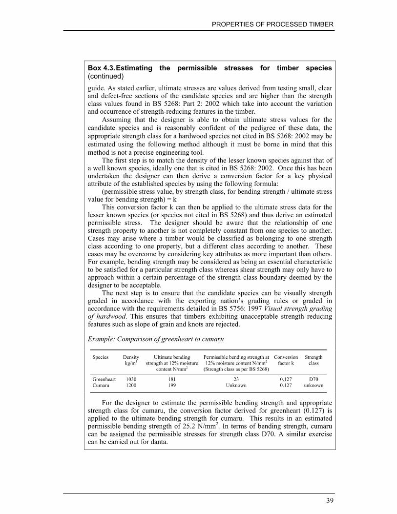
PROPERTIES OF PROCESSED TIMBER
39
Box 4.3.Estimating the permissible stresses for timber species(continued)guide. As stated earlier, ultimate stresses are values derived from testing small, clearand defect-free sections of the candidate species and are higher than the strengthclass values found in BS 5268: Part 2: 2002 which take into account the variationand occurrence of strength-reducing features in the timber.
Assuming that the designer is able to obtain ultimate stress values for thecandidate species and is reasonably confident of the pedigree of these data, theappropriate strength class for a hardwood species not cited in BS 5268: 2002 may beestimated using the following method although it must be borne in mind that thismethod is not a precise engineering tool.
The first step is to match the density of the lesser known species against that ofa well known species, ideally one that is cited in BS 5268: 2002. Once this has beenundertaken the designer can then derive a conversion factor for a key physicalattribute of the established species by using the following formula:
(permissible stress value, by strength class, for bending strength / ultimate stressvalue for bending strength) = k
This conversion factor k can then be applied to the ultimate stress data for thelesser known species (or species not cited in BS 5268) and thus derive an estimatedpermissible stress. The designer should be aware that the relationship of onestrength property to another is not completely constant from one species to another.Cases may arise where a timber would be classified as belonging to one strengthclass according to one property, but a different class according to another. Thesecases may be overcome by considering key attributes as more important than others.For example, bending strength may be considered as being an essential characteristicto be satisfied for a particular strength class whereas shear strength may only have toapproach within a certain percentage of the strength class boundary deemed by thedesigner to be acceptable.
The next step is to ensure that the candidate species can be visually strengthgraded in accordance with the exporting nation’s grading rules or graded inaccordance with the requirements detailed in BS 5756: 1997 Visual strength gradingof hardwood. This ensures that timbers exhibiting unacceptable strength reducingfeatures such as slope of grain and knots are rejected.
Example: Comparison of greenheart to cumaru
Species Densitykg/m3
Ultimate bendingstrength at 12% moisture
content N/mm2
Permissible bending strength at12% moisture content N/mm2
(Strength class as per BS 5268)
Conversionfactor k
Strengthclass
Greenheart 1030 181 23 0.127 D70Cumaru 1200 199 Unknown 0.127 unknown
For the designer to estimate the permissible bending strength and appropriatestrength class for cumaru, the conversion factor derived for greenheart (0.127) isapplied to the ultimate bending strength for cumaru. This results in an estimatedpermissible bending strength of 25.2 N/mm2. In terms of bending strength, cumarucan be assigned the permissible stresses for strength class D70. A similar exercisecan be carried out for danta.

MANUAL ON THE USE OF TIMBER IN COASTAL AND RIVER ENGINEERING
40
Box 4.3.Estimating the permissible stresses for timber species(continued)
Example: Comparison of greenheart to danta
Species Densitykg/m3
Ultimate bendingstrength at 12% moisture
content N/mm2
Permissible bending strength at12% moisture content N/mm2
(Strength class as per BS 5268)
Conversionfactor k
Strengthclass
Greenheart 1030 181 23 0.127 D70Danta 1000 137 Unknown 0.127 unknown
For the designer to estimate the permissible bending strength and appropriatestrength class for danta the conversion factor derived for greenheart (0.127) isapplied to the ultimate bending strength for danta. This results in an estimatedpermissible bending strength of 17.4 N/mm2. When compared with the minimumpermissible stresses for the strength classes detailed in BS 5268: Part 2: 2002, interms of bending strength, danta can be assigned the permissible stresses for strengthclass D50.
Where ultimate stress values are not available for lesser known species or thereis little confidence in the reliability of the data, then density may be used to gain a‘ball park’ estimation of strength. Density is an important factor that can influencethe strength and stiffness of timber and correlates well with certain properties such asbending strength, hardness and compression strength parallel to the grain. However,these estimations should only be used for comparative purposes. The strength oftimber is obviously important, forming one of the key design parameters, but sincetimber is a natural material, there is some variability even within single species.
4.5. DURABILITY
Timber is an inherently durable material, which is resistant to most biological attackprovided it remains dry. However, prolonged wetting leads to a risk of decay bywood rotting fungi, although susceptibility varies according to the wood species, andthis is known as ‘natural durability’. Resistance to mechanical damage also variesaccording to the species.
4.5.1. Mechanical damage
Timber is a variable material and its natural durability is affected by many factors.Two problems occur when timber is used in marine construction: biological attackand mechanical abrasion. The latter is a significant problem for structures located onmobile beaches – particularly those with a low tidal range since this concentrates theattack on a small part of the structure. Abrasion is caused by impacts from beachmaterial carried around or over the structure, predominantly by waves. It can result in

PROPERTIES OF PROCESSED TIMBER
41
significant loss of section of timber components and significantly reduce the servicelife of structures.
The abrasion resistance of different species of timber in this type of situationmay be influenced by the effect of marine soft rot fungi and also by the extent ofsaturation of the timber. Timber with a high moisture content (i.e. above the fibresaturation point) is weaker than dry timber. The action of soft rot fungi can causesoftening at the surface of the timber, accelerating the rate of mechanical abrasion asthe decayed timber is easily eroded.
The effects of abrasion can be limited by the selection of durable timber, but thedetailed design of the structure and provision of sacrificial sections to protect exposedstructural components can also be very effective. Since the purpose of groynes is toreduce the transport of beach materials, they can be particularly susceptible toabrasion and further details of the problem and counter measures are discussed inSection 6.2.7.
Mechanical abrasion of timber may be uneven and this may be a reflection ofbeach conditions or variation in the natural properties of the timber species such asdensity, for example. The greatest abrasion usually occurs in the intertidal zonebetween the lower limit of shingle and the average high tide level. The rate of wearwill vary from beach to beach and from species to species. Once installed, however, itis possible to estimate the rate of wear of the timber components by carrying outannual inspections of the structures and thereafter taking remedial measures withsacrificial pieces to minimise wear problems.
Different species of timber will have varying resistance to abrasion. There is nostandard test to determine the abrasion resistance of timber species but comparativetests have, and can be, carried out on sites where abrasion is a recognised problem. Insome instances, field testing may not be practicable so the designer will have to relyon species of timber with a proven track record. Reliance on a narrow range ofspecies is a problem that has been discussed earlier (see Section 4.2.1) as potentialcandidate species which have not been accepted within the industry may be rejectedby the designer as there is little knowledge regarding abrasion resistance.
It is possible to make a fairly accurate judgement as to the abrasion resistance ofcandidate species by assessing alternative mechanical properties. Density andhardness are two properties which can provide an indication as to the abrasionresistance of candidate species. The greater the density and hardness, the greater theprobable abrasion resistance. For candidate species of similar density, the specieswith the greater hardness will probably have better abrasion resistance.
4.5.2. Biological attack
Durability may be a natural feature of the timber or it may be imparted by the use ofpreservative treatments. However, before discussing the technical factors, critical tothe successful preservation of timber, it is important to gain an understanding of theattack mechanism and natural durability.
Fungal decay and insect attackWood rotting fungi obtain their food by breaking down wood cell walls. They cancause staining, decay, loss of strength and can cause complete disintegration of the

MANUAL ON THE USE OF TIMBER IN COASTAL AND RIVER ENGINEERING
42
timber component. For fungal decay to occur, the timber must have a moisturecontent in excess of 20%. The first line in defence in preventing fungal decay is tokeep the timber below this decay threshold. This is not possible in timber for use inthe marine and fresh water environments. Therefore, reliance must be placed on gooddesign and the specification of naturally durable timber species or timber that hasbeen treated in the appropriate manner with a wood preservative.
There are two types of wood rotting fungi that can affect the strength of timbercomponents in marine and fresh water environments. These are soft rot and wet rottype fungi. The main risk of fungal decay affecting timber structures in the marineand fresh water environments comes from wet rot type fungi attacking timber withinand above the intertidal zone. Such fungal attack can cause extensive pockets ofdecay and severe loss in strength. As wet rot type decay develops, it usually does soat an ever increasing rate with the result that the subsequent loss in strength of thecomponent also occurs at an ever accelerating rate. Soft rot fungi will attack timberthat is immersed in water. Soft rotting type fungi erode the outer layers of the timbercomponents at a relatively slow rate. The outer surfaces are typically dark, soft and‘cheesy’ in texture. Therefore regular inspections of the structure should beincorporated as part of any maintenance regime.
The presence of insect attack in marine and fresh water constructions is usuallylimited to the perishable sapwood section of a component or can be symptomatic offungal decay being present.
Marine borer attackThe principal agents causing biodeterioration of timber in the marine environment aremarine borers, which can cause severe damage in relatively short periods of time. InUK and other temperate waters two types of borer are of greatest significance; themollusc Teredo spp. (shipworm) and the crustacean Limnoria spp. (gribble).
Descriptions of Limnoria spp. and Teredo spp. are provided in Box 4.4 and Box4.5.
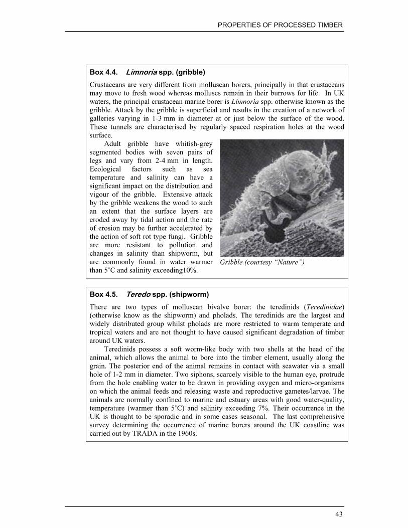
PROPERTIES OF PROCESSED TIMBER
43
Box 4.4. Limnoria spp. (gribble)Crustaceans are very different from molluscan borers, principally in that crustaceansmay move to fresh wood whereas molluscs remain in their burrows for life. In UKwaters, the principal crustacean marine borer is Limnoria spp. otherwise known as thegribble. Attack by the gribble is superficial and results in the creation of a network ofgalleries varying in 1-3 mm in diameter at or just below the surface of the wood.These tunnels are characterised by regularly spaced respiration holes at the woodsurface.
Adult gribble have whitish-greysegmented bodies with seven pairs oflegs and vary from 2-4 mm in length.Ecological factors such as seatemperature and salinity can have asignificant impact on the distribution andvigour of the gribble. Extensive attackby the gribble weakens the wood to suchan extent that the surface layers areeroded away by tidal action and the rateof erosion may be further accelerated bythe action of soft rot type fungi. Gribbleare more resistant to pollution andchanges in salinity than shipworm, butare commonly found in water warmerthan 5˚C and salinity exceeding10%.
Gribble (courtesy “Nature”)
Box 4.5. Teredo spp. (shipworm)There are two types of molluscan bivalve borer: the teredinids (Teredinidae)(otherwise know as the shipworm) and pholads. The teredinids are the largest andwidely distributed group whilst pholads are more restricted to warm temperate andtropical waters and are not thought to have caused significant degradation of timberaround UK waters.
Teredinids possess a soft worm-like body with two shells at the head of theanimal, which allows the animal to bore into the timber element, usually along thegrain. The posterior end of the animal remains in contact with seawater via a smallhole of 1-2 mm in diameter. Two siphons, scarcely visible to the human eye, protrudefrom the hole enabling water to be drawn in providing oxygen and micro-organismson which the animal feeds and releasing waste and reproductive gametes/larvae. Theanimals are normally confined to marine and estuary areas with good water-quality,temperature (warmer than 5˚C) and salinity exceeding 7%. Their occurrence in theUK is thought to be sporadic and in some cases seasonal. The last comprehensivesurvey determining the occurrence of marine borers around the UK coastline wascarried out by TRADA in the 1960s.

MANUAL ON THE USE OF TIMBER IN COASTAL AND RIVER ENGINEERING
44
Box 4.5.Teredo spp. (shipworm) continued
The precise mode of settlement ofjuveniles on to wood is disputed. Oneschool of thought is that colonisation isassociated with softened regions of woodwhich have suffered fungal and bacterialattack. Another view is that teredinidswill colonise timber irrespective ofbiological pre-conditioning. Thegrinding action of the shells produces finefragments of wood which are ingestedand the cellulose component digested. Teredo spp. (‘shipworm’) (courtesy
Simon Cragg)The animal remains in the same tunnel throughout its life and lines it with a
calcareous deposit. The animals avoid intruding into neighbouring tunnels and inwarmer waters some species can grow up to 2 m in length. Shipworm is extremelydifficult to detect and survey methods are detailed in Chapter 9.
Natural durabilityTimber species differ markedly in their resistance to biological attack and naturaldurability may be defined as the natural resistance of the timber to such attack. It isimportant to recognise that this term only refers to the heartwood of timber species.The sapwood of all timber species has no natural durability. The heartwood of somespecies, e.g. greenheart, will last for decades in ground and/or marine contact whereasthat of European redwood will suffer destruction in a comparatively short space oftime. Historically, natural durability was recognised through experience of workingwith various species. However, in the nineteenth century field tests providedspecifiers with more reliable test data enabling categorisation of the timbers’ naturaldurability.
In more recent times natural durability ratings have been determined by one oftwo methods. Ratings can be based on field tests where 50 mm x 50 mm stakes ofheartwood have been exposed in ground contact and assessed at regular intervals.Larger section sizes will last longer in ground contact. For example if a 50 mm ×50 mm heartwood stake of oak lasts 15-25 years in ground contact, it follows that a100 mm × 100 mm stake can be expected to last 30-50 years. The drawbacks of thistest method are that it is time consuming and subject to human error.
A faster, more objective method to assess durability is to carry out weight losstests with specific laboratory organisms as detailed in BS EN 350: Durability of woodand wood-based products. Natural durability of solid wood, Part 2: 1994 Guide tonatural durability and treatability of selected wood species of importance in Europe.This presents a list of 20 softwoods, 107 hardwoods and 7 commercial speciesgroupings.
BS EN 350 identifies five natural durability ratings. The equivalent BritishStandard BS 5589: 1989 Preservation of timber also classifies timber into five

PROPERTIES OF PROCESSED TIMBER
45
durability ratings. The durability ratings are summarised in Table 4.7. For a widerrange of species the reader should refer to BS EN 350: Part 2 and BS 5589.
The natural durability ratings defined in BS 5589 and BS EN 350 do notconsider the resistance of the timber to marine borer attack. It is important torecognise that resistance to marine borers does not necessarily parallel resistance tofungal decay. In addition, natural durability in any climatic or geographical regionmay vary according to the vigour of wood destroying flora and fauna. It is importanttherefore to carry out a risk assessment based on local information about theperformance of wood species and the presence of wood destroying organisms.
Table 4.7. Classification of natural durability
BS EN 350 BS 5589 Approximate lifein ground contact
Examples
Class 1 Verydurable
Very durable >25 years Jarrah, greenheart,iroko and ekki.
Class 2 Durable Durable 15-25 years European oak, sweetchestnut, robinia andyellow balau
Class 3 Moderatelydurable
Moderatelydurable
10-15 years Caribbean pitch pine,Douglas fir, sapeleand European larch
Class 4 Slightlydurable
Non-durable 5-10 years Europeanredwood/whitewood
Class 5 Notdurable
Perishable > 5years Beech, sycamore andash
Natural durability may also vary within the tree itself, especially for thosetimbers that are classified as being very durable. In some species such as ekki, someanatomists have described a layer of timber between the sapwood and heartwood ascomprising ‘transition wood’ which is not as durable as fully formed heartwood. BSEN 350 recognises this condition in ekki. With reference to BS EN 350: Part 2 thetransition wood in ekki is classified as moderately durable. Transition wood isgenerally slightly paler than the fully formed heartwood.
As previously stated, it is important to recognise that natural durability againstfungi does not necessarily indicate durability against marine borer attack. Themajority of timber species are susceptible to marine borers but a limited number ofspecies are recognised as being resistant, i.e. naturally durable in the marineenvironment. BS EN 350: Part 2 identifies a number of timber species and recentresearch has investigated the resistance of a number of traditional and lesser knownspecies to attack by marine borers which is described in Box 4.6.

MANUAL ON THE USE OF TIMBER IN COASTAL AND RIVER ENGINEERING
46
Box 4.6. Resistance of timbers to marine borers – laboratory trialsCurrently, BS EN 275: 1992 Determination of the protective effectiveness againstmarine borers details the protocol for establishing preservative efficacy in the marineenvironment and may be used to form the framework to assess natural resistance oftimber species to marine borers. However, BS EN 275 specifies a five year testperiod: too long a period for screening tests to be economically viable, especially ifproducers are encouraging designers to specify lesser known species. In order toaddress this problem a new test protocol has been developed to prove the potentialsuitability of candidate species through a rapid laboratory assay. If the candidatespecies fails in the laboratory test, it will almost certainly fail if ‘field’ tested.
There are two types of marine borer present in UK waters. The crustaceanLimnoria spp. (gribble) is ubiquitous whereas the mollusc Teredo spp. (shipworm)tends to be limited to the south west coast. In this pilot study, durability was assessedby measuring the rate of digestion of samples by the marine borer Limnoriaquadripunctata under forced feeding conditions over a number of days. The aims ofthe pilot study were two-fold: to determine the resistance to Limnoria spp. of lesserknow species of timber thought to be suitable for use in the marine environment andto investigate the feasibility of introducing a new fast track screening protocol forsuitable candidate species. The preliminary results of this pilot study aresummarised below.
Attack on a range of timbers over 15 days compared with rate for Scots pinesapwood
Species Rank %Red.
Species Rank %Red.
Species Rank %Red.
Bruguiera spp.(mangrove)
1 100 Uchi torrado 15 74.9 Balau 29 17.2
Cupiuba 2 98.6 Jatoba 16 73.4 Louro petro 30 10.1Acaria quara 3 95.8 Angelim vermelho 17 69.9 Oak 31 5.4Wonton 4 94.3 Robinia 18 68.5 Louro itauba 32 4.8Ekki 5 94.1 Purpleheart I 19 67.9 Scots pine sapwood
CONTROL33 0
Louro gamela 6 91.9 Rhizophora spp.(mangrove)
20 65.8 Piquia marfim 34 -4.4
Ayan 7 85.4 Purpleheart II 21 55.9 Jarana 35 -12.7Denya 8 84.5 Xylocarpus spp. 22 47.3 Sapupira 36 -22.2Piquia 9 83.2 Muiracatiara 23 44.3 Castanha de arara 37 -41.4Favinha prunhela 10 81.7 Dahoma 24 42.5 Abiurana 38 -41.8Ipe 11 80.7 Guariuba 25 41.2 Tetekon 39 -42.9Cumaru 12 80.1 Greenheart 26 41.0 Favinha spp. 40 -74.7Amiemfo samina 13 80.0 Bompagya 27 30.5 Essia 41 -144.3Massaranduba 14 76.6 Heratiera spp.
(mangrove)28 22.8 42
% Red. Refers to the % reduction in rate of digestion when the results forcandidate species are compared to Scots pine sapwood control blocks. Negativevalues mean that for that particular timber, animals produced more pellets than forthe control indicating that the candidate species was more vulnerable to gribbleattack.

PROPERTIES OF PROCESSED TIMBER
47
Box 4.6. Resistance of timbers to marine borers – laboratory trials(continued)These initial data have revealed interesting results and have identified a number ofpotential species that may be used in the marine environment. Several commerciallyavailable candidate species from South America have been identified such ascupuiba, louro gamela, cumaru and piquia, for example. In addition, wonton denya(okan) and ayan from West Africa have also been identified as potential species. Atthe time of writing, further research is being carried out. The initial theory drawnfrom this research is that if the candidate species is considered to be vulnerable togribble under laboratory conditions, it is probable that this species will fail againstgribble at a faster rate in service than a species with an established track record.However, due to the small sample size and inherent assumptions the results shouldnot be regarded as anything other than indicative. Resistance to Limnoria spp. doesnot necessarily indicate resistance to Teredo spp. Alternative test methods to thosedescribed in BS EN 275 designed to assess the resistance to Teredo spp. are beinginvestigated at the time of writing.
It is also important to recognise that local site conditions will also affect thelongevity of timber structures. For example, a timber that is naturally resistant intemperate waters may be more vulnerable in tropical waters. In addition, brackishsites such as estuaries frequently support a greater hazard of shipworm than salinewaters. Timber species with a silica content of 0.5% or greater are thought to haveresistance against marine borer attack. It is thought that a silica aggregate deposited incertain timber species has a blunting effect on the boring apparatus of marine borers.Resistance may also be imparted by toxic extractives present in the timber (see Table4.8).
Table 4.8. Natural defence mechanisms against marine borer attack
Defencemechanism
How Disadvantages
Silica Silica aggregate form amechanical resistance
Difficult processing of timberSilica content has to exceed 0.5%
Alkaloids Natural toxic extractives Alkaloids can leach out after several yearsEco-toxicity of leaching out of alkaloids isnot known
Density andhardness
Great strength andcoherence form amechanical resistance
Difficult processing of timberPerforms best in combination with otherdefence mechanisms
Details of the actual incidence of marine borer attack in the UK and methods ofmitigating are given in Section 6.2.2.

MANUAL ON THE USE OF TIMBER IN COASTAL AND RIVER ENGINEERING
48
4.6. PRESERVATION OF TIMBER
Historically, the wood preservation industry has enjoyed considerable success inprolonging the service of timber with a range of wood preservatives. However, someof these compounds have been banned from use and others are being restricted. Theprincipal reason for the banning and restriction of certain compounds is their reportedeco-toxicity. Greater environmental awareness and the need to developenvironmentally benign preservatives have driven preservation research and, sincethe 1970s, many new chemicals and products have been tested for their efficacy.Some commercially available treatments are still being appraised for their long termperformance.
The primary objective of the industrial pre-treatment, or pressure treatment oftimber with preservatives, is to ensure that even when timber is serving in ahazardous environment it remains sound throughout the design life of the component.Therefore, where naturally durable timber species are not available, it is possible touse non-durable preservative treated timber species in their place. However, thespecifier must be aware of a number of limitations governing the use of preservativetreated timbers in the marine and fresh water environment, for example, preservativeefficacy and timber permeability.
In simple terms, pressure treatment encapsulates the timber component with apreservative envelope which prevents access by fungi or other wood destroyingorganisms to the vulnerable, untreated core of the component. The treatability of thetimber governs the depth of this preservative envelope and the subsequent end use ofthe component. Pressure treatment is the most effective method of application for themajority of wood preservatives although, by itself, pressure treatment is by no meansa universal solution to increasing the longevity of non-durable timber species inhazardous environments.
4.6.1. Types of timber preservative and their treatment methods
Three types of preservative products may be considered appropriate for non-durabletimber that is expected to serve in hazard classes HC3, HC4 or HC5, (see Chapter 6for explanation). These are:
• water-borne preservatives applied by high pressure treatment process• solvent and water-borne preservatives applied by low pressure treatment process• tar-oil preservatives.
Once again applied by high pressure treatment process. As well as considering themost suitable formulation, it is also important to specify a timber that is permeable towood preservatives, especially if the treated timber is to be used in a marineenvironment, where high preservative loadings are desirable. Such selection must,however, take account of the relevant physical requirements such as strength andresistance to abrasion.

PROPERTIES OF PROCESSED TIMBER
49
Water-borne preservatives applied by high pressure treatment processThere are two main types of water-borne preservatives applied by high pressuretreatment processes. The first type is a traditional preservative based on achromated/copper/arsenate (CCA) formulation. The high pressure industrial treatmentprocess forces the active ingredients deep into the timber structure where theybecome chemically ’fixed’ to the timber cells and remain leach resistant aftertreatment. CCA preservatives provide a highly effective protection against all formsof decay and insect attack for timbers used in all hazard classes HC1-HC5. CCApreservatives have been used safely and effectively for over 50 years including therenowned Tanalised timber, for example. However, since January 2004 theEuropean Commission has restricted the use of preservatives containing CCA.Therefore, preservative manufacturers are now offering new chrome-and-arsenate-free products, which are proving to be effective for applications in hazard classesHC1-HC4. These products, based on copper and a secondary biocide, provide analternative water-borne preservative for high pressure treatments. Treatment byeither type of preservatives results in a pale green/brown colouring to the treatedtimber.
Typical applications and recommendations for high pressure treatments aredetailed in Table 13 of BS 8417 and are a guide to typical schedules. They do notform the basis of a guarantee that specific penetration classes and retentions havebeen met.
Figure 4.3 illustrates and describes a typical high pressure or ‘full cell’ treatmentprocess that delivers water-borne preservatives into timber for use in high hazardsituations. Where the hazard is not so severe or permeable timber is being treated, amodified treatment process called the ‘empty cell’ process is used. No vacuum stageis applied at the start of this type of treatment and air in the wood is compressedduring the pressure phase. When the treatment vessel is drained of preservative, theair in the timber expands, forcing out more preservative. This results in lowerretention values than for the ‘full cell’ process, but can have significant cost-savingbenefits when high loadings of preservative are not required.
® Tanalised is a registered trademark of Arch Timber Protection.

MANUAL ON THE USE OF TIMBER IN COASTAL AND RIVER ENGINEERING
50
Timber is loaded into the industrial treatment vesseland a vacuum is applied to remove air from thetimber. This vacuum period is varied according tothe treatability of the timber species.
Treatment vessel is flooded with preservative at therequired concentration of active ingredient.
Pressure is applied for the required period so that thenecessary penetration and retention values areachieved.
The treatment vessel is drained of preservative and afinal vacuum is applied to remove excesspreservative from the timber. When vented to theatmosphere, low pressure inside the timber alsodraws in surface preservative. The timber is left todry and for the preservative to become fully ‘fixed’within the timber cells. Timber treated with CCAtype preservatives must be held for at least 48 hoursafter treatment and until surfaces are dry before thetimber can be moved. This allows excesspreservative to be collected in an enclosed area.
Figure 4.3. Summary of the ‘full cell’ high pressure treatment process (diagramscourtesy of Arch Timber Protection)

PROPERTIES OF PROCESSED TIMBER
51
Light organic solvent and micro-emulsion based preservatives applied by lowpressure treatment processThese preservative products can be used to protect timbers used in hazard classesHC1 and HC2 (internal building timbers) and also in hazard class HC3 (coatedexternal building timbers out of ground contact). They cannot be used for any directground or water-contact applications.
The light organic solvent type preservatives (LOSPs) are being replacedincreasingly by the micro-emulsion types, which are dispersed in water rather thansolvent, reducing the emission of volatile organic compounds into the atmosphere.The LOSPs continue to be preferred for the particular treatment of decorative joinerycomponents, minimising any raising of the wood grain. The micro-emulsion productsare used extensively for the treatment of timber frame and truss material and generalbuilding timbers.
If these products are used to treat external joinery (HC3) then the timber shouldbe subsequently protected with a maintained and appropriate surface coating. If theprotective coating should fail the preservative performance may be compromised.
Both of these treatments leave the appearance of the timber virtually unchanged,although a colour can be added to the treatment for identification purposes, ifrequired. The treatments also leave the dimensions of the timbers unchanged, unlikethe water-borne high pressure treatments, which can swell the treated timbers.
LOSPs and water-borne micro-emulsion based preservatives are delivered usingthe double vacuum or Vac-Vac® process, summarised in Figure 4.4. Typical lowpressure Vac-Vac® treatment schedules are detailed in Table 12 of BS 8417.
Coal-tar preservativesTar-oil or creosote-based preservatives have been used extensively in marine andfluvial environments and at one point were the pre-eminent preservatives usedworldwide. A range of national specifications exists for creosote type preservativesand the specifier should initially refer to BS 8417. Since June 2003, the use ofcreosote-based wood preservatives in the European Union has been restricted toprofessional and industrial use only, owing to concerns that benzo-a-pyrene, one ofthe active compounds in creosote, is thought to be more liable to trigger cancer thanwas previously thought. However, there are also technical reasons why creosotetreatments have declined in their use, one of which is the migration of thepreservative to the wood surface under certain conditions.
The principal technical disadvantages of creosote are that it is not possible toapply paint or stain systems to creosote treated timber. The wood is greasy to thetouch and is vulnerable to ‘bleeding’ – the creosote migrates to the surface of thetimber and can be deposited on exposed skin, clothing and animals. In manyrecreational applications, this is undesirable and has led to its restriction. In suchsituations, if naturally durable timber is not specified, water-borne CCA or newgeneration type preservatives tend to be favoured.
Typical treatment schedules for timber to be treated under high pressure with tar-oil preservatives are summarised in Table 14 of BS 8417. Similarly to water-bornetreatments, creosote is delivered into timber under high pressure using the ‘full cell’process summarised earlier in Figure 4.3.

MANUAL ON THE USE OF TIMBER IN COASTAL AND RIVER ENGINEERING
52
Initial vacuum applied to remove air from thetimber. Duration of the vacuum is determined by thetreatability of the timber species.
Vacuum held and treatment vessel flooded withpreservative. Release of vacuum forces thepreservative into the wood cells under atmosphericpressure. A low pressure may be applied for moreresistant species or to achieve a higher specification,depending upon the end use of the timber.
Second vacuum applied to evacuate excesspreservative. Venting to atmospheric pressure drivessurface preservative back into the timber and leavesthe surface drip dry.
Figure 4.4. Summary of the Vac-Vac® low pressure treatment process (diagramscourtesy of Arch Timber Protection) Vac-Vac is a registered trademark of ArchTimber Protection
Sections 4.6.1 and 4.6.2 describe the current standards relevant to timberpreservation and summarise the key points presented in BS 5268-5, BS 5589,BWPDA manual and BS 8417. The standards are comprehensive, but theinformation presented above can be summarised as a series of decision processes asin Table 4.9. The decision tree is based on the guidance given in Annex B of BS8417 and the italicised text details the decision tree process for European redwoodtimber revetments serving in contact with fresh water.

PROPERTIES OF PROCESSED TIMBER
53
Table 4.9. Stages of the decision process for using preservative treatment
Decisionstep
Action Decision/ (example)
1 Identify timbercomponent and serviceconditions
(bank revetment for fresh waterenvironment)
2 Identify species to beused
Where a durable timber species is selectedpreservative treatment may not be necessary(European redwood)
3 Consider service factorand the need forpreservative treatment
Depends upon the timber durability class,hazard class, service factors and desiredservice life(Service factor D for European redwood infresh water. Essential to use preservativetreatment to minimise fungal hazard whennon-durable timber is used as fresh waterrevetments)
4 Select desired servicelife
Three desired service lives are identified: 15,30 or 60 years30 years
5 Select service type A preservative should be selected that isappropriate for the timber species serving inthe specified hazard class.(CCA type wood preservative conforming toBS 4072)
6 Select preservativerequirements
Select preservative performancerequirements from Table 4 in BS 8417(Penetration class P9 Retention value 25kg/m3)
4.6.2. Understanding the standards for preservative treatment
In the UK, preservative treated timber for use permanently or intermittently in contactwith sea or fresh water is usually specified in accordance with the guidance in eitherBS 5268-5, BS 5589, the British Wood Preserving and Damp-proofing Association(BWPDA, 1999) manual or, more currently, BS 8417. For all applications ofpreservative treated timber described in this manual, the preservatives must beapplied under pressure.
BS 8417: 2003 Preservation of timber – recommendations is the most recentguidance document to be published in the UK. This standard describes the levels ofpreservative treatment to be achieved in terms of penetration and retention ofpreservative in the analytical zone of the timber which, previously, was not addressed

MANUAL ON THE USE OF TIMBER IN COASTAL AND RIVER ENGINEERING
54
in the process driven standards BS 5268-5 and BS 5589. Therefore, BS 8417 may bedescribed as a target-driven standard. BS 8417 is a key document for specifierswhich is supported by essential guidance detailed in the following documents.
1. BS EN 335-1: 1992 Hazard classes of wood and wood-based products againstbiological attack – Classification of hazard classes
2. BS EN 350-1: 1994 Durability of wood and wood-based products. Naturaldurability of solid wood. Part 1. Guide to the principles of testing andclassification of the natural durability of wood
3. BS EN 350-2: 1994 Durability of wood and wood-based products. Naturaldurability of solid wood. Part 2. Guide to natural durability and treatability ofselected wood species of importance in Europe
4. BS EN 599-1: 1997 Durability of wood and wood-based products –Performance of preventive wood preservatives as determined by biological tests– specification according to hazard class
5. BS 144: 1997 Specification for coal tar preservatives6. BS 1282: 1999 Wood preservatives – guidance on choice, use and application7. BS 4072: 1999 Copper/chromium/arsenic preparations for wood preservation8. BS 5707: 1997 Specification for preparations of wood preservatives in organic
solvents9. BS 5268:-5: 1989 Code of practice for the preservative treatment of structural
timber10. BS 5589: 1989 Standard code of practice for the preservation of timber11. BWPDA Manual: 1999.
The previously published BS 5268-5 and BS 5589 standards, and the BWPDPAmanual (1999) provide detailed technical guidance on the type and use of variouspreservative treatments. The many schedules and variants of the basic proceduresused in the UK are testament to the complexity and need for judicious use of effectivetimber preservation.
These documents are widely recognised throughout the wood preservingindustry in the UK. BS 5268-5 describes the preservative treatment of timber used forstructural purposes. In addition, BS 5268-5 classifies service factors based on safetyand economic considerations related to wood destroying organisms and the need forpreservative treatment of non-durable timber for a particular service category. Thisinformation is also presented in BS 8417 and is summarised in Table 4.10.

PROPERTIES OF PROCESSED TIMBER
55
Table 4.10. Service factors based on safety and economic considerations
Consequence of failure of timbercomponent
Need for preservativetreatment(or specifying naturallydurable timber species)
Servicefactor code
Negligible Unnecessary A
Where remedial treatment action ofreplacement is simple and preservationcan be regarded as an insurance againstthe cost of repairs
Optional B
Where remedial action or replacementwould be difficult and expensive
Desirable C
Where collapse of structures wouldconstitute a serious danger to persons orproperty
Essential D
The level of preservative treatment recommended depends not only on the riskof biological attack but also on the expected service life of the timber components.Desired service life values detailed in BS 8417 and its predecessors (BS 5268-5, BS5589 and BWPDA manual) are not guarantees of performance but merely indicationsof the expectation against which the recommendations for timber treatment are drawnup. Moreover, timber preservation is not a panacea for poor design and construction.Durability by design is an essential factor that must be considered, and incorporatingthe principles of good design (see Section 7.3.1) can enhance the level of protectionprovided by the preservative treatment.
BS 5589 describes the preservative treatment schedules to be used for timberthat is to be introduced to various hazardous environments and details preservativetype, concentration of preservative solution where appropriate, timber treatability andtreatment procedures. In short, BS 5589 can be described as a process drivenstandard based on previous experience and the long term track records of establishedwood preservatives such as creosote and CCA (copper/chromium/arsenic) containingpreservatives. The BWPDA manual describes additional performance criteria called‘Penetration (P) Classes’ for the penetration depth of preservatives into timber. These‘P’ classes also incorporated into BS 8417 are discussed later in this section and areinfluenced by the permeability of the timber, in other words, the ease in which thetimber can be treated.
4.6.3. Classification of the permeability of timber to preservative treatment
The life expectancy of non-durable or perishable timber components may beenhanced by pressure treatment with an appropriate wood preservative. The efficacy

MANUAL ON THE USE OF TIMBER IN COASTAL AND RIVER ENGINEERING
56
of the pressure treatment and the service applications of the timber will also begoverned by the permeability or treatability of the timber to the preservative. BS5589 and BS EN 350-2 describe four categories of permeability or treatability, listedin Table 4.11 below. BS 8417 simplifies these four permeability classes into either‘permeable wood’ or ‘resistant wood’.
Table 4.11. Classification of permeability classesTreatability classBS 5589 BS EN 350
Description Explanation Examples
Permeable 1 Easy to treat Easy to treat; sawn timber can bepenetrated completely by pressuretreatment without difficulty
European beech,pine sapwood
Moderatelyresistant
2 Moderatelyeasy to treat
Fairly easy to treat; usuallycomplete penetration is not possible,but after 2-3 hours pressuretreatment, more than 6 mm lateralpenetration (depth) can be reachedin softwoods and a large proportionof hardwood vessels will bepenetrated.
European elm,pine (heartwood),sitka sprucesapwood
Resistant 3 Difficult totreat
Difficult to treat; 3-4 hours pressuretreatment may not result in morethan 3-6 mm lateral penetration
Douglas fir,European larch,obeche, spruceheartwood
Extremelyresistant
4 Extremelydifficult totreat
Virtually impervious to treatment;little preservative absorbed evenafter 3-4 hours pressure treatment
Basralocus,greenheart,jarrah, Europeanoak, teak
Note: Permeability rating for ‘pines’ are generalisations and the reader should refer to BS EN350-2 for further details.
Where high preservative loadings are required to protect timber, only thosespecies that are permeable or moderately permeable should be used. Deeper andmore uniform preservative penetration into timber may be achieved by incising thewood. For example Douglas fir, although classified as being moderately durableagainst biodeterioration, has been used extensively in the marine environment.However, the sapwood of Douglas fir is moderately resistant to treatment and theheartwood is classified as resistant. Greater longevity can be achieved by incising thesurface of the timber with sharp blades at regular intervals to improve the penetrationof preservative fluids into the wood.

PROPERTIES OF PROCESSED TIMBER
57
Table 4.12. Preservative treatment schedules as detailed in BS 5589
CCA1 treatment Creosote2 by pressure processFresh water (HC4) and salt water (M) Fresh water (HC4) Sea water (M)
Timberspecies
Vacuumperiod(minutes)
Pressureperiod(minutes)
CCA conc.(g/L)
Minaverage netretention(kg/m3 )
Extendedpressureperiod(minutes)
Minaverage netretention(kg/m3 )
Extendedpressureperiod(minutes)
Europeanredwood
180 200 180
Beech 120 400 180Pitch pine 180 180 240Elm 180 200 180Douglas fir 180 180 240Larch
60 180 50 160
120 200 180
1 CCA water-borne preservative should be applied by full cell process in compliance withBS 4072: Part 1. Vacuum of –0.8 bar applied followed by impregnation at 12.4 bar.N.B. CCA Treatments have been prohibited for use in marine environments from30/06/2004.
2 Creosote preservative should comply with type 1 of BS 144: Part 1.
Where high populations of marine borer are known to be present, all sawntimber requiring preservative treatment, with the exception of elm, should be incisedprior to treatment. Incising can also reduce the severity of splitting in service.
The timber treatments summarised in Tables 4.12-4.14 are intended to providemaximum protection to timber for use in fresh water and marine environments. Theexpected service life of the components is determined by the extent of wood decayingfungi and/or marine borers in the local environment.
To obtain a high, consistent standard of preservative treatment, considerationshould be given to using the timbers in the round. The sapwood band is usually morepermeable than heartwood and this should ensure a greater depth of preservativepenetration and, also, greater preservative retention in the treated zones.Furthermore, there are mechanical advantages of using timber in the round, sincepoles are stronger than sawn timber of equivalent dimensions as there is less graindisruption in round timber. BS 8417 defines three desired service lives of 15, 30 and60 years. The treatment schedule, preservative type, preservative concentration andpermeability of the timber will influence the ability to achieve the desired service life.
Assuming good design and detailing preservative treated timber can, in practice,last far in excess of the desired service life expectancies stated in BS 8417. For allpressure treatments, all cross-cutting, mortising and drilling of timber componentsshould be carried out before treatment. If this is not possible then any surfaceexposed by further matching/working after treatment should be liberally treated withan appropriate preservative to minimise the risk of attack.
Table 4.12 describes the treatment processes with water-borne CCA typepreservative and creosote preservatives detailed in BS 5589 that should be followedin order to achieve the desired level of protection in service. These processes haveevolved over many years of experience. The key difference between BS 5589, BS5268-5 and the recently published BS 8417 is that BS 8417 (which will supercede BS5589 and BS 5268-5) defines the level of penetration and retention of preservative

MANUAL ON THE USE OF TIMBER IN COASTAL AND RIVER ENGINEERING
58
required to protect timber in its service environment. Table 4.13 summarises theguidance given in BS 8417 for timber treated with CCA preservatives for use inbrackish and fresh water environments and Table 4.14 details the guidance given inBS 144 for timber treated with coal-tar creosote containing preservatives. Thesetables describe the treatment processes for these two types of timber preservativewhich reflected their long established excellent track record for use in marine andfresh water environments.
Table 4.13. Treatment recommendations for CCA preservatives
Desired service life15 years 30 yearsPermeable or resistant wood Permeable or resistant wood
Hazardclass
Servicefactor
Penetrationclass
Retention Penetrationclass
Retention
Timber infresh water
4 D P9 25 kg/m3* P9 25 kg/m3*
Timber insalt water
5 D Not permitted for use in marine environment (from 30/06/2004)
* These values are interim critical values adjusted to take into consideration the industrialexperience of the UK wood preserving industry and are an interpretation of the processguidance detailed on BS 5589 and BS 5268-5.
Table 4.14. Treatment recommendations for creosotes conforming to BS 144
Desired service life15 years 30 yearsPermeable or resistant wood Permeable or resistant wood
Hazardclass
Servicefactor
Penetrationclass
Retention Penetrationclass
Retention
Timber infresh water
4 D P9* 320 kg/m3* P9* 350 kg/m3*
Timber insalt water
5 D P9* 320 kg/m3* P9* 350 kg/m3*
* P + R values refer only to the analytical zone. The analytical zone is the area wherepreservative has been delivered into the timber.
To meet certain ‘P’ (preservative penetration) classes it may be necessary toincise the timber. The major implication of introducing target ‘P’ classes is that thespecifier should have an understanding of the technical properties of the timber(s) tobe treated. It may not be always possible to achieve the more onerous penetrationclasses required for preservative treatment in certain species of timber that are non-durable and resistant to treatment.
Analysis of species with permeable and moderately permeable sapwood canprovide a good indication of whether the minimum sapwood retention values havebeen achieved and this is a requirement to establish if the desired treatment level

PROPERTIES OF PROCESSED TIMBER
59
specified in BS 8417 has been achieved. BS EN 351-1 sets out the performancecriteria for the maximum permissible number of non-conforming samples, assessed aspart of a quality assurance programme within the industrial pre-treatment plant, basedon whether the timber is classified as ‘permeable’ or ‘resistant’ to treatment. Manytreatment plants are automated and many preservers issue treating certificates toassure end users that the timber has been treated in accordance with the relevantschedule detailed in the end users’ specification.
Qualitative analysis of treated timber may be undertaken to determine that therequired preservative loadings have been applied. These tests are detailed in Parts 1and 2 of BS 5666: Methods of analysis of wood preservatives and treated timber.
Table 4.15 is based on data presented in both the BWPDA manual and BS 8417and summarises the information detailing the penetration classes and the analyticalzones for determination of preservative retention in accordance with BS EN 351-1.
Table 4.15. Penetration classes and definition of the analytical zones
Penetration class Penetration requirement Analytical zone
P1 None 3 mm from lateral face
P2 Minimum 3 mm lateral and 40 mmaxial penetration into sapwood
3 mm lateral into sapwood
P3 Minimum 4 mm lateral penetrationinto sapwood
4 mm lateral into sapwood
P4 Minimum 6 mm lateral penetrationinto sapwood
6 mm lateral into sapwood
P5 Minimum 6 mm lateral and 50 mmaxial penetration into sapwood
6 mm lateral into sapwood
P6 Minimum 12 mm lateral penetrationinto sapwood
12 mm lateral into sapwood
P7 Roundwood only: Minimum 200 mmlateral penetration into sapwood
20 mm into sapwood
P8 Full sapwood penetration Sapwood
P9 Full sapwood and minimum 6 mmpenetration into heartwood
Sapwood and 6 mm into exposedheartwood
In addition to defining the performance characteristics for preservativepenetration and retention classes, BS 8417 also sets out the limits for what are knownas critical values (CVs). Critical values may be defined as the minimumconcentration of preservative required to inhibit the activity of wood-destroyingorganisms (fungi and/or insects) in treated timber.
CVs are applicable to new timber preservatives which have not been incommercial use sufficiently long enough for the relevant commercial and fieldexperience to have been amassed. For example, CCA preservatives have a proven

MANUAL ON THE USE OF TIMBER IN COASTAL AND RIVER ENGINEERING
60
track record in use of about 70 years and the track record for creosote is even longer.Therefore CV limits are based on laboratory experience, not practical experience.With reference to new preservatives for use in fresh water and marine environments,for a service life of 15 years, the preservative should achieve the same penetrationclass (P9) as for more traditional treatments (CCA or creosote) and the CV should bethe same as that achieved in laboratory trials. However, should a service life of 30 oryears be desired, the CV derived from laboratory trials should be multiplied by afactor of 1.5 or up to 2.5, depending upon the expected service life and treatability ofthe specified timber. See Table 4.16.
Table 4.16. Treatment recommendations for preservatives for which an appropriateCV value as described in BS EN 599-1 is available
Desired service life15 years 30 years 60 years
Hazardclass
Servicefactor
Permeable andresistant wood
Permeable andresistant wood
Permeable andresistant wood
Timber infresh water
4 D P9 CV1 P9 CV1.5 P9 2.0
Timber insalt water
5 D P9 CV1 P9 CV1.75 P9 2.5
As stated earlier, industrial timber preservation provides a protective envelopearound the component. In environments where there is a high risk of abrasion and/orwear, the protective envelope may be eroded and expose vulnerable, unprotectedtimber.
Where preservative treatment is not desirable or practicable, owing to a high riskof abrasion in service or strength-limiting factors, the designer may specifyheartwood of timber species that are considered to be naturally durable and, whererelevant, resistant to attack by marine borers. Table 4.17 details a number ofappropriate timber species. The information is principally taken from BS 5589.

PROPERTIES OF PROCESSED TIMBER
61
Table 4.17. Suitability of timber (heartwood) for use in sea and fresh water
Species suitable for useuntreated in sea water(M)
Species suitable for useuntreated in fresh water(4)
Species suitable, if treated,for use in sea water (M) andfresh water (4)
Andaman padauk American pitch pineBasralocus Caribbean pitch pineEkki Douglas firGreenheart ♦ ElmIroko European larchJarrah European redwoodKapur Japanese larchOkanOpepeAfrican padauk*Belian*Iroko*Muninga*Pyinkado*Red louro*Teak*
All timber that is rated asvery durable (VD) suitablefor this application
* Species of timber detailed in BWPDA manual (1999).♦ Care should be taken with greenheart as the sapwood is not as easily distinguished from
the heartwood as within other species such as ekki, for example.
The list of species given in Table 4.17 is by no means exhaustive and otherspecies, especially lesser known species, may be suitable for marine and fresh waterenvironments.
4.6.4. Environmental considerations and European Union legislation
The Biocidal Products Directive now being introduced will standardize approvalregimes for all biocidal products, including wood preservatives, across the EuropeanCommunity. The comprehensive controls already in place in the UK under theControl of Pesticides Regulations will result in this directive having a minimal impactin the UK. However, the Directive does mean that approval for all existing biocidalproducts will have to be reviewed. Following the review period, the woodpreservation industry expects stricter controls to be implemented. These controls maytake the form of stricter voluntary regulation driven by the industry itself.
Section 4.6.3 briefly described water-borne preservative such as those containingsalts of copper, chromium and arsenic (CCA). The use of CCA containingpreservatives has been the subject of intense debate throughout Europe.Consequently, the Scientific Committee on Toxicity, Ecotoxicity and theEnvironment (CSTEE) has undergone a protracted consultation process to assess therisks to health and to the environment of arsenic in wood preservatives and of theeffects of further restrictions on its marketing and use.

MANUAL ON THE USE OF TIMBER IN COASTAL AND RIVER ENGINEERING
62
In November 2002, the amendment to Council Directive 1976/769/EECrestricted the use of timber treated with CCA solutions in marine waters. Thisrestriction came into force on 30th June 2004. However, CCA treated timber maystill be used as constructional timber in fresh water areas and brackish waters. CCAtreated timber may also be used as structural timber in earth-retaining structures,public and agricultural buildings, office buildings, industrial premises and bridgesand bridgework. In certain situations, this restriction will force the designer to designwith tropical hardwoods or concrete and steel.
Timber preservatives not containing arsenic but suitable for use in marine andfresh water environments are available within the EU. However, these formulationstend to be more expensive, and confidence in the service life of the treated timber isnot fully established.
As noted in Section 4.6.1, the use of creosote-based wood preservatives in theEuropean Union was restricted from June 2003 for health and technical reasons.Certain uses of creosote-treated wood are still permitted provided the treatment hasbeen carried out in an industrial installation or by professionals under specifiedconditions.
4.7. PROPERTIES OF RECYCLED TIMBER
Recycled timber can provide a valuable source of material. Old, redundant structuresmay be viewed as ‘industrial forests’ and their yield will depend entirely upon thequality of the reclaimed timber and its condition. Reclaimed timber (see Figure 4.5)should be set apart from ‘new’ timber and certain guidelines should be followed. Thefirst question that needs answering is: ‘What species am I reclaiming?’. It is criticalthat the right species for the job is selected. By identifying the species, the salvagercan judge whether it is worth recycling the timber and for what markets or use thismaterial is appropriate.
This section briefly describes the pertinent points to consider when reclaimingtimber. Potential sources of reclaimed timbers include posts and beams fromdemolished warehouses, pilings and beams from dismantled piers and planks, andpiles from dismantled groynes. For all reclaimed timber, it is important that themembers are stripped of all ironmongery prior to reprocessing otherwise costly andtime-consuming damage can be caused to the machinery.

PROPERTIES OF PROCESSED TIMBER
63
Figure 4.5. Reclaimed hardwood piles awaiting sorting, machining and grading(courtesy John Williams)
Generally, the timbers should be machined so that worn, weathered and damagedsurfaces are removed to expose the underlying timber. This will inevitably result in aloss of section. The freshly exposed surfaces are now in a presentable condition toenable the timber to be graded to the appropriate visual or machine-grading standard(Figure 4.6).
In addition to naturally occurring strength-reducing features such as knots andslope of grain, the timber may have been significantly affected by man-made defectssuch as holes for fixings and notches. In practical terms, where high volumes oftimber are being recycled, heavily notched timbers should be machined so that theseareas are removed. Where notches are infrequent, they may be considered as ‘knots’and the grading rules for knots may be applied. Holes for fixings can also beconsidered as knots.

MANUAL ON THE USE OF TIMBER IN COASTAL AND RIVER ENGINEERING
64
Figure 4.6. Sorted and part machined reclaimed hardwood timber (courtesy JohnWilliams)
The timbers should be assessed for any signs of biodeterioration such as fungaldecay and marine borer attack. Typically, survey techniques include decay detectiondrilling and hammer soundings.
Mechanical damage may affect the strength of recycled timber significantly. Ifthere are visible signs of impact, there may be a risk of compression failure within thetimber. If compression failure is suspected, the timber should be rejected and cross-cut to exclude the impact area. Large section timbers such as balau, for example,may have been cut in such a manner that the member contains boxed heart. Boxedheart arises when the weaker, less durable timber comprising the pith in the centre ofthe tree is protected by stronger durable material. Examining the end grain usuallyidentifies timbers that exhibit boxed heart. If the pith is visible, then the member

PROPERTIES OF PROCESSED TIMBER
65
contains boxed heart. Provided that the boxed heart is still armoured by older maturetimber after cleaning, the reduced section may be used. However, it may not beadvisable to place the recycled member in a critical part of any structure.
If the reduction of the section results in exposure of the pith along the length ofthe member then it should be rejected. Generally, most large section timbers that haveboxed heart are easily identifiable by heart checks at the end grain. Heart checks arecharacteristic of old, large section timbers that have dried out. Research in the USAhas shown that heart checks have little effect on recycled timbers used as columns butthey do cause a significant reduction in the modulus of rupture when used as beams.
There are other factors to consider. Large section timbers that have been servingin dry conditions will be well seasoned and, as such, will be dimensionally stable. Insituations where little timber movement is expected, recycled timbers may havesignificant advantage over large sections of green timber.
The moisture content of the timber is vital. For example, should water loggedtimber members be broken-down to smaller section members, it is inevitable that asthey dry out they may experience some distortion. This may be minimised byweighing down stacks of the broken down members to restrain the timber. Thepotential effects of timber movement should be considered when using recycledmaterials.
The properties provided within Appendix 1 are generally applicable to recentlyproduced timber. Whilst recycled timber of the same species is likely to have similarcharacteristics it may, depending on age and exposure, be more brittle and moredifficult to work. In addition, repeated loading may have caused damage which,although difficult to detect, may have weakened the timber. If there is doubt as to theproperties or suitability of recycled timber a qualified timber strength grader shouldbe consulted.
Recycled timber deemed to be unsuitable for further structural work should bemade available for other uses (including landscape or decorative features) rather thandisposal to landfill sites.
4.8. STRUCTURAL TIMBER COMPOSITES
Although timber provides high specific strength and stiffness, its natural variabilityhas, traditionally, challenged the engineer. Through efficient strength-gradingprocedures and judicious selection of material, highly efficient structural compositematerials have been developed. The major advantages of structural timber compositesare that large dimensions are available and that higher strength characteristics can beachieved compared with those of the raw material. Essentially, the manufacture ofthese composites involves transforming relatively low value raw material into highvalue engineered products.
The structural timber composites described below are suitable for external use asdefined in Hazard class 3 with the appropriate preservative treatment, if manufacturedfrom non durable materials. Their suitability for use in Hazard classes 4 and 5 shouldbe checked with the manufacturer and whilst there are only limited examples ofmarine applications identified at the time of writing, there is thought to be

MANUAL ON THE USE OF TIMBER IN COASTAL AND RIVER ENGINEERING
66
considerable potential for their further development and application to coastal andriver structures.
4.8.1. Glulam
The definition of glued laminated timber (Glulam) in European Standards is that it ismanufactured from laminates of timber glued together with the grain in the laminatesrunning essentially parallel. The laminates in Glulam are normally sawn sectionswhich are planed to a smooth surface before gluing.
The laminates are butt jointed using finger jointing techniques so the overalldimensions of the finished product are determined by the manufacturing premises andtransportation facilities. The laminates are bonded together to form a member thatacts as a single structural unit. Where appropriate the laminates are preservative-treated prior to manufacture. The manufacture of glulam is strictly controlled by aseries of British and European standards which focus on batch testing of the productfor mechanical strength and glue line integrity.
The manufacture of glulam with finished lamination thicknesses of not morethan 45 mm is covered by BS EN 386: Glued laminated timber – Performancerequirements and minimum production requirements. This standard replaces BS4169: 1988 Specification for manufacture of glued laminated timber structuralmembers. The BS EN 386 requirements apply to structural members used in Serviceclasses 1 and 2. For members used in Service class 3, special precautions need to betaken as, for example, in the use of weather-resistant adhesives as defined in BS EN301: Adhesives, phenolic and aminoplastic, for load-bearing timber structures.Classification and performance requirements.
The general aim of BS EN 386 is to ensure that reliable and durable bonding isachieved consistently. To this end it lays down requirements relating to premises,staff and equipment as well as technical aspects such as the moisture content of thelaminates at the time of gluing, the orientation and lay-up of the laminates, crampingpressures, curing time and temperature for the glues. Emphasis is laid on qualitycontrol, with routine daily testing of finger joints and laminate gluelines beingrequired as part of the production process. The manufacturer is required to keepdetailed records of every production run. External control through independent thirdparty quality certification to oversee the quality of production is required.
Glulam (Figure 4.7) is used extensively in the UK and the European mainlandand has been used in a wide variety of applications ranging from high profile‘flagship’ developments to industrial premises. It is available as ‘off the shelf’prefabricated components or specialised sections can be manufactured to order, forexample, curved sections. Glulam may also be manufactured in the vertical form.

PROPERTIES OF PROCESSED TIMBER
67
Figure 4.7. Glulam (courtesy TRADA Technology)
Glulam has a number of advantages over solid timber components. Glulam isavailable in large cross sections and lengths at a controlled moisture content. It can bemanufactured in curved, straight or cambered shapes. The strength of glulam isdetermined by the grade and species of timber, both hardwoods and softwoods, usedin its manufacture. This makes glulam a very versatile material that can be used in theconstruction of many structural forms.
The laminating process disperses the natural strength-reducing features such asknots and sloping grain throughout the member. This produces an engineered productthat has higher strength and improved dimensional stability. Most commerciallyavailable glulam comprises laminates from a single species and grade. Most ‘off theshelf’ glulam is manufactured from European whitewood which is resistant topreservative treatment. Therefore, for external uses, glulam manufactured from pre-treated European redwood or from naturally durable hardwoods such as iroko, whichhas an established track record, is preferred. Other lesser known hardwoods wouldhave to be assessed by a competent authority.
The advantages of such an engineered structural composite is that strength-reducing features such as knots may be eliminated by cross-cutting. In addition, abalance between maximising strength with attention to efficient use of materials maybe achieved by sandwiching laminates with strength-reducing features between‘defect’ free laminates so that the higher quality, stronger laminates are positioned inplaces of maximum stress. Also, in the lower and mid-range strength classes,

MANUAL ON THE USE OF TIMBER IN COASTAL AND RIVER ENGINEERING
68
laminated timber has a higher characteristic bending strength than the timber fromwhich it is made because defects are eliminated or spread through the glulam section.
Glulam can be either homogenous, where all the laminates are the same strengthclass of timber, or combined, where the outer laminates (one-sixth of the depth onboth sides) are a higher strength class than the inner ones.
For mechanically fastened joints in glulam, as in solid timber, the formulae inEurocode 5 require the characteristic density of the material rather than its strengthclass. Lamination averages out this value, so the load-carrying capacity ofmechanically fastened joints calculated from Eurocode 5 will, in many cases, beincreased by laminating the timber. Eurocode 5 also gives advantageous rules forplain dowelled joints which are useful in glulam structures.
4.8.2. Mechlam
Mechanically laminated timber consists of members which are straight or slightlycurved and which are formed from laminations connected together by dowel-typefasteners. The use of mechanically laminated timber for construction in Europe waswell established by the start of the nineteenth century and comprised thick-bolted orrod-connected laminations. Connections between adjacent layers are normally madewith stainless steel dowels force driven through pre-drilled holes in the laminationswhich have smaller diameters than the dowels. This produces a tight fit at theinterface.
4.8.3. Steel and timber composites – prestressed decking plates
Laminated decking plates are made up of individual laminations which are heldtogether by nailing or adhesive bonding. In the case of prestressed plates there is, inaddition, a permanent lateral pressure which guarantees continued friction contactbetween the faces of the laminations and any unbonded adjacent faces.
Stress-laminating may be defined as a permanent effect due to controlled forcesimposed upon the structure. Timber plates are normally prestressed by means of steelbars or tendons. Care must be taken when designing prestressed timber plate systemsas incorrect moisture content specification can lead to a loss in prestressing forces asa result of timber shrinkage. Of course, the steel should be corrosion resistant. Steelmay also be substituted for glass reinforced fibre rods. Prestressing rods are usuallybonded into the structure which increases corrosion resistance and results in goodload-carrying capacity.
Steel reinforced timber elements serve in high duty environments althoughlocalised reinforcing may be employed to repair/upgrade structures. Reinforcement isespecially worth considering where elemental design is restricted through therelatively low tensile strength of timber transverse to the grain direction. Steelreinforcement may also be used to increase resistance to shear.

PROPERTIES OF PROCESSED TIMBER
69
4.8.4. Laminated veneer lumber
Laminated veneer lumber (LVL) consists of veneers, typically of an initial thicknessof 3.2 mm which are peeled from logs and bonded together, generally parallel to oneanother. LVL offers similar advantages to glulam. It attains even more strength sincethe laminations are thinner and timber growth features have greater dispersionthroughout the member. Similarly to glulam, LVL offers properties which may beused for many load-bearing forms such as principal beams for bridges, for example.LVL is only manufactured in long straight boards which are subsequently rip-sawninto long members. Therefore, although it is possible to order LVL cut into tapered orcurved forms, it is more economical to use it in straight sections.
The manufacturing process begins by soaking debarked logs in hot water for 24hours. They are then rotary peeled to produce veneers, typically 3-4 mm thick whichare clipped into sheets 2 m wide. After drying, phenol formaldehyde adhesive isapplied to the veneers which are normally laid with the grain running parallel to forma mat of desired thickness. The joints are staggered vertically to minimise their effecton the strength of the LVL. The mat of veneers is then pressed at high temperatureand then cross-cut and rip-sawn to the required dimensions.
As with glulam manufacture, quality control during manufacture includesregular testing of the quality of the glue bond and of the mechanical properties suchas bending strength of the finished material.
4.8.5. Parallel strand lumber
Parallel strand lumber (PSL) is manufactured in the USA mainly from Douglas firand Southern yellow pine. As in the manufacture of LVL, logs are peeled intoveneers. The sheets of veneers are then clipped into strands up to 2400 mm in lengthand 2-3 mm in thickness. A phenol formaldehyde adhesive is used which is mixedwith wax to enhance the dimensional stability of the finished product. The adhesive isapplied to the oriented strands which are fed into a rotary belt press and cured underpressure by microwave heating. PSL emerges as a continuous billet which is then cutand trimmed to the required dimensions.
4.8.6. Laminated strand lumber
Laminated strand lumber (LSL) is also manufactured in the USA. LSL ismanufactured from low value aspen strands up to 300 mm in length and 30 mm inwidth. After drying the chips are coated with a polyurethane adhesive and the chipsare oriented in a direction parallel to the panel length. The resulting mat is heated andpressed to produce a finished panel which is cut to the required sections.
4.8.7. Advanced wood composites
In the USA, the research and development of wood–plastic composites is receivingmuch attention. This has largely been borne out of the combination of the restrictions

MANUAL ON THE USE OF TIMBER IN COASTAL AND RIVER ENGINEERING
70
of using pressure treated softwood (creosote and CCA) and a growing reluctance tospecify durable tropical hardwoods. By far the biggest driver is the classification ofredundant pressure treated components as hazardous waste. The cost implications ofdisposal are prohibitive and, historically, tend not to have been considered as part ofthe life cycle cost analysis of a structure.
In addition, new shore front structures require large service loads and designersare steered towards steel and concrete solutions. However, there is marketopportunity for wood–plastic composites and the US Navy is working closely withresearchers to develop and use carbon reinforced engineered thermoplastic timbercomposites. Typically, these composites consist of engineered particles, fibres orflour. In addition, carbon fibre reinforced composites are being assessed, such asglulam with carbon fibre reinforcements at the interfaces.
An advanced wood–plastic composite (WPC) describes the material formedwhen wood material is impregnated with a monomer. The aim of developing WPCs isto combine the tensile strength of wood fibres with the abrasion resistance,dimensional stability, hardness and incompressibility of the polymeric materials usedin the manufacture of the WPC.
4.8.8. The use of structural composites in the marine and fresh waterenvironments
There are issues which the designer should be aware of when considering the use ofstructural timber composites in a submerged environment. Mechanically or gluedlaminated timber has a track record of being used in the marine environment. Thereare many instances in boat building where the keel has been made of glued laminatedtimber.
The adhesives used in the manufacture of glulam and other structural timbercomposites tend to be phenol resorcinol-formaldehyde (PRF). These adhesives have aproven track record and are used in the manufacture of external and marine gradeplywood.
Provided the designer chooses a naturally durable timber, there should be littledifficulty in designing a mechlam or glulam structure for service in the marineenvironment, although there are few instances where this has been carried out. Theprincipal advantage of considering glulam as a possible solution is that smallersection sizes of timber may be utilised which can widen the choice of candidatespecies.
If choosing to use a non-durable timber, timber preservation needs to beconsidered. This can pose considerable problems. Firstly, the expected restrictions inthe use of CCA type preservatives on the marine environment restricts the choice ofpreservative. Secondly, abrasion of the components can breach the preservativeenvelope which can shorten the expected service life of the structure. The feasibilityof using preservative treated components may also be restricted by the size of thechamber available to accept the finished component. Treatment of individuallaminates is not available from all glulam manufacturers.
The use of materials such as laminated veneer lumber (LVL) and parallel strandlumber (PSL), for example, should be limited to Hazard class 3 environments. The

PROPERTIES OF PROCESSED TIMBER
71
manufacturer of the product should always be consulted by the designer to check thatthe manufacturer is confident that their product is fit for the intended purpose.
In most external structural applications the service life of structural timbercomposites can be virtually unlimited. The use of modern external class adhesivesensures excellent glueline durability. The main threat to the service life of suchcomponents out of ground and water contact is a rise in moisture content. However,good design coupled with good maintenance procedures can minimise the risk ofdeterioration.
In summary, mechlam and glulam timber may be used in marine and fresh waterenvironments provided they are manufactured out of suitably durable materials orpreservative treated materials that conform to European legislation. Other structuraltimber composite such as LVL and PSL should only be used in environments wherethe service risks are no greater than those defined by Hazard class 3.


73
5. Responsible procurement of timber
The selection and specification of appropriate materials has a significant influence onthe environmental impact and sustainability of schemes as well as the performanceand durability of the timber structures.
It is essential that the inherent advantages of timber are not negated byirresponsible procurement practices. This will necessitate a more detailed assessmentof the requirements of a particular scheme and the properties (includingenvironmental provenance) of timbers used in any solution. Whilst selection willinclude assessment of engineering and economic issues in addition to environmentalconsiderations, particular attention will be needed to ensure that the use of tropicalhardwoods, especially those which are not demonstrably from legal and sustainablesources, is clearly justified. However, care must be taken to ensure that timber is notso difficult to procure that it is substituted by more environmentally damagingmaterials (see Chapter 2).
5.1. ENVIRONMENTAL CONSEQUENCES OF TIMBER USE
Tropical hardwoods have properties which make them attractive for coastal and riverstructures, however in recent years there has been increasing public concern relatingto environmental damage caused by logging of forests.
5.1.1. Forest loss and degradation
The complex biological structure within natural tropical forests makes themparticularly vulnerable to over-exploitation which can result in irreversibledeforestation. The Global Forest Resources Assessment 2000 (FAO, 2001) preparedby the United Nations Food and Agricultural Organization estimates that the 14.6million hectares of natural forest are lost each year and a further 1.5 million hectaresper year of natural forests were converted to forest plantations. This is to some extentoffset by the expansion of natural forests and forest plantations (at a rate of 5.2million hectares per year) and the rate of deforestation in the 1990s was slower thanthat of the 1980s. However, most of the forest losses were in the tropics and it iswidely accepted that the startlingly rapid rate of tropical forest destructionexperienced in recent years is unsustainable.
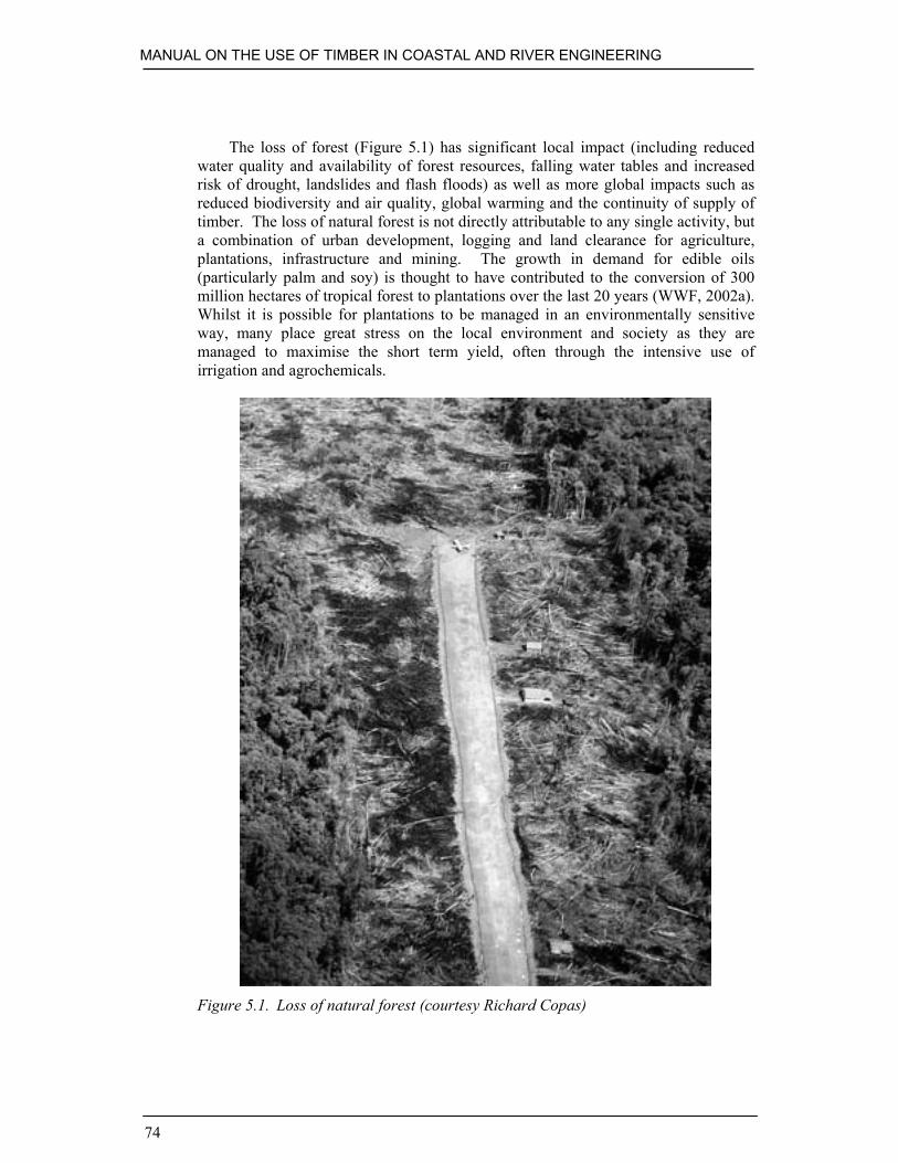
MANUAL ON THE USE OF TIMBER IN COASTAL AND RIVER ENGINEERING
74
The loss of forest (Figure 5.1) has significant local impact (including reducedwater quality and availability of forest resources, falling water tables and increasedrisk of drought, landslides and flash floods) as well as more global impacts such asreduced biodiversity and air quality, global warming and the continuity of supply oftimber. The loss of natural forest is not directly attributable to any single activity, buta combination of urban development, logging and land clearance for agriculture,plantations, infrastructure and mining. The growth in demand for edible oils(particularly palm and soy) is thought to have contributed to the conversion of 300million hectares of tropical forest to plantations over the last 20 years (WWF, 2002a).Whilst it is possible for plantations to be managed in an environmentally sensitiveway, many place great stress on the local environment and society as they aremanaged to maximise the short term yield, often through the intensive use ofirrigation and agrochemicals.
Figure 5.1. Loss of natural forest (courtesy Richard Copas)

RESPONSIBLE PROCUREMENT OF TIMBER
75
Illegal logging is another major contributor to forest degradation and loss, butdue to the nature of the activity it is very difficult to quantify. Illegal loggingdeprives governments of revenue which, in turn, has significant impact on socialprovision such as education, sanitation and healthcare. It is seldom undertaken withany regard to sustainable forest management and may lead to increased agriculturalconversion, mining, poaching, human settlement and forest fires. An initiative by theG8 governments to reduce illegal logging is summarised in Box 5.1.
Box 5.1. Illegal loggingFollowing a meeting of G8 finance and foreign ministers in May 1998 a G8 ActionProgramme on Forests was announced (G8, 1998). This included the following onillegal logging:
“Illegal logging robs national and subnational governments, forest owners andlocal communities of significant revenues and benefits, damages forest ecosystems,distorts timber markets and forest resource assessments and acts as a disincentive tosustainable forest management …”
The G8 members gave a commitment to:
• encourage the sharing of information and assessments as a basis for developingcountermeasures
• improve economic information and market transparency• assess the effectiveness of internal measures to control illegal logging• implement obligations under international agreements to combat bribery and
corruption• work with interested partner countries to develop their capacity to assess illegal
logging and develop and implement counter measures.
More recently, the UK Government commitment to tackling illegal logging wasreiterated: “The UK Government has taken the lead in tackling illegal logging. Ourforests are the single most important stabilising feature of the land's surface. Thecommitment that the Government made to purchase timber products only from legallylogged, sustainably managed sources is a significant step. It is also a challengingtarget. This commitment has been acknowledged across Government, and an inter-departmental buyers group has been established to advise and monitor onperformance.” (DEFRA, 2001).
Recent analysis (Report Controlling the Trade in Illegal Logging, Royal Instituteof International Affairs (RIIA) 2002; WWF Report 2002 on Illegal log procurementby governments Timber Footprint of the G8 and China) suggests that betterinformation on the extent of illegal logging is now available and much more could bedone to tackle illegal logging. At an EU level, the Forest Law Enforcement,Governance and Trade (FLEGT) initiative suggests that tighter controls on timberimports should be under consideration to help prevent forest crime. “Illegal loggingand forest crimes play a significant part in the ongoing extensive destruction of thetropical forest (an area of about five times the size of Belgium is lost every year), withconsequent loss of government revenues, estimated at up to $15 billion per yearglobally, and of funds for social services and attempts to reduce poverty. So there isnow general agreement that measures should be taken to prevent the import into theEU of illegally sourced timber”. FLEGT Report 2002.

MANUAL ON THE USE OF TIMBER IN COASTAL AND RIVER ENGINEERING
76
Whilst unsustainable logging for export does contribute to the loss anddegradation of forests, only a relatively small proportion of the harvested timber isactually exported. In many areas much of the timber is used for firewood, localconstruction or wood products such as paper. Nevertheless, the responsiblespecification and purchase of timber can have a significant impact in discouragingillegal and unsustainable practices.
5.1.2. The case for using timber
Timber is renewable and is an environmentally responsible material option if recycledor if known to come from sustainably managed forests. When this is the case, thereare very strong environmental arguments in its favour – with relatively low energyrequired for its production and (apart from transport and processing) being virtually‘carbon neutral’. Indeed, all forests sequester carbon from the atmosphere both inliving biomass and in forest soils. Living forests also have important functions in theregulation of other cyclical processes important to the earth’s climate – particularlyair quality and the water cycle.
5.1.3. Sustainable forest management
Most types of forest can be managed sustainably, that is to say, harvested periodicallyfor timber and other products in such a way that their productive benefits for futuregenerations are not compromised. It can be argued that sustainable management andexploitation of forests provides an economic raison d’être which discouragesconversion for agricultural or plantation use. Many European forests have beenmanaged for hundreds of years and such management is not necessarily incompatiblewith high levels of biological diversity, rather careful long term management canenhance the biological diversity of forests.
Whilst the term ‘sustainable forest management’ will mean different things todifferent people, there is a consensus amongst many forestry professionals that it is a‘multi-dimensional balancing act’ (Upton and Bass, 1995) involving economic andsocial as well as environmental interests. This is succinctly expressed by principle 1bof the Non-Legally Binding Statement of Forest Principles (Rio, 1992): “Forestresources and forest lands should be sustainably managed to meet the social,economic, ecological, cultural and spiritual needs of present and future generations.”
5.2. PROCUREMENT POLICY AND ISSUES
There is an urgent and widely recognised need to encourage and implementsustainable forest management worldwide. This is evident from internationalagreements, government commitments and intense lobbying from environmental non-governmental organisations. There are strong drivers for both public and privateentities to adopt procurement policies that will favour legally harvested wood fromsustainably managed forest. Government and trade measures to protect forests are of

RESPONSIBLE PROCUREMENT OF TIMBER
77
diminished effectiveness in a market where stolen, illegally harvested or plunderedwood is freely available and frequently much cheaper than legitimately producedtimber. Any procurement procedure which does not incorporate environmentalconsiderations will tend to favour decisions based only on price and thus encourageillegal logging and exploitative forestry.
5.2.1. Governmental policy and agreements
Concern at governmental level to encourage and implement sustainable forestmanagement worldwide has manifested itself in several international agreements orforest protection processes as shown in Box 5.2.
Box 5.2. International agreements on timber trade and sustainableforest management
• Agenda 21 of the Rio Earth Summit of 1992 – particularly Chapter 11 The Non-Legally Binding Statement of Forest Principles – Rio, 1992
• International Tropical Timber Agreement (ITTA) 1994• The Helsinki Accord 1996• The Montreal Accord and the Santiago Declaration 1995• The UNCED agreements, including UNCBD, the International Panel on Forests
(IPF), the International Forum on Forests (IFF), CITES (The Convention onInternational Trade in Endangered Species of Wild Fauna and Flora), and theAnti-Bribery Convention
• OECD and G8 statements.
The UK government has reiterated its policy on several occasions in recentyears, perhaps most clearly in July 2000 when the Environment Minister stated
“ … current voluntary guidance on environmental issues in timber procurementwill become a binding commitment on all central government departments andagencies actively to seek to buy timber and timber products from sustainable andlegal sources, for example, those identified under independent certification schemessuch as that operated by the Forestry Stewardship Council.” (excerpt of speech byMichael Meacher, House of Commons 28th July 2000).
A recent report by the Environmental Audit Committee suggests that whilst theUK government policy is commendable, implementation by government departmentsand agencies is not yet widespread:
“Not only does the government have a responsibility to lead by example inenvironmentally sound timber procurement practices; it also has, through its buyingpower, the potential to change the nature of the timber markets through theprocurement decisions that it makes … While Government rhetoric has beenlaudable, we see no systematic or even anecdotal evidence of any significant changein the pattern of timber procurement since July 2000 …” (House of Commons, 2002).
The Dutch government has taken a significant initiative in supporting sustainableforest management, not least through the minimum requirements shown in Box 5.3.

MANUAL ON THE USE OF TIMBER IN COASTAL AND RIVER ENGINEERING
78
The UK, Dutch and other governments are also assisting producing nations, includingIndonesia, under bilateral agreements.
Box 5.3. Dutch minimum requirements(Dutch Ministry for Nature Management, 1997)– Bold type from the original textMinimum requirement 1Local forest management should demonstrably and sufficiently show thatattention has been paid to the integrity of ecological functions and the continuityof socioeconomic and sociocultural functions of the forest on the basis of therelevant criteria and indicators.
Minimum requirement 2Local forest managers should have an adequate management system
Minimum requirement 3The certifying body is independent, demonstrably complies with internationalregulations as to organisation and procedures followed and has the necessaryforest management expertise.
5.2.2. Procurement based on understanding
In a world where diminishing and important natural resources need to be conserved,responsible procurement decisions can only be made with an understanding ofenvironmental considerations. The consequences of ignoring this can beconsiderable, impacting on both the project and the client as well as the widerenvironment, as is shown in Table 5.1. The key to minimising controversy forspecifiers is to be able to demonstrate that a logical and responsible procurementprocess is followed and that environmental considerations are included at all stagesduring the scheme development. At the most basic level this requires that timberbeing procured can be proven to come from forests that are being legally harvested(see Table 5.2). However, legality alone does not ensure sustainable yieldproduction, so it is also highly desirable that timber comes from forests that are being‘sustainably managed’ or at least managed in a way that harvesting is not overlydetrimental and progress is being made towards sustainable management. Ultimately,all timber (both temperate and tropical) should come from legal, sustainable,managed forestry.
The UK currently imports about 700 000 m3of tropical hardwoods per year(Environmental Audit Committee, 2002) and whilst only a relatively small proportionof this is thought to be used in coastal and river works, these applications form asignificant market for a number of species such as greenheart (from Guyana) and ekki(or azobe from West and Central Africa). Although the trade in tropical hardwoodshas been the main focus of controversy, environmental and social problems resultingfrom the loss and degradation of forest areas are not limited to tropical regions.Responsible specification and procurement of temperate soft and hardwoods is alsoneeded.

RESPONSIBLE PROCUREMENT OF TIMBER
79
Table 5.1. Possible consequences of ignoring environmental issues in timberprocurement
Public Sector Private Sector
• Inefficient or inappropriate use oftimber
• Inefficient or inappropriate use oftimber
• Public criticism and delay to schemeapproval / construction due to review oftimber selection
• Concern by potential investors / clientsdue to increasing environmentalawareness
• Rejection of timber selection /specification by client due to non-conformity with environmentalaccreditation (e.g. BS EN ISO 14001),policy or reporting requirements
• Non-conformity with the requirementsof environmental accreditation (e.g. BSEN ISO 14001) or other commitments(e.g. WWF 95+ group)
• Legal challenges delaying or preventingscheme construction
• Public criticism and damage toreputation
Legal and sustainable procurement is anobligation upon government, governmentagencies and local authorities under Agenda21 and other agreements.
Private clients are under no legal obligationto observe environmental criteria. However,this does not mean that they might not beaffected by consequences of uninformeddecision-making.
5.2.3. Relevant guidance
A recently published report (Procurement of timber products from ‘legal &sustainable sources’ by Government & its executive agencies, ERM, 2002) issuggesting a basis for public sector timber procurement in the UK. This reportaddresses appropriate sustainability criteria and recognises that it is necessary toadopt a progressive approach to eliminating illegal and unsustainable timber.
The preference for legal and sustainable timber is consistent with governmentpolicy and whilst it is not mandatory for private sector organisations it should beconsidered best practice. In order to identify whether a timber is legal and sustainableit is essential to have verification of where it has come from. This requires the ‘chainof custody’ to be recorded and possibly verified through independent auditing.
It is also important to realise that not all definitions of legality and sustainabilityare consistent. For the purposes of the guidance provided in this document, thedefinitions based on those developed for the UK Government (ERM, 2002) have beenadopted (Table 5.2).
It is hoped that this will allow sufficient flexibility to meet particular technicalrequirements, whilst encouraging sustainable forest management and ensuringminimum standards. It is recognised, however, that assessing different types ofevidence will be outside the competence of most individuals and it is proposed thatthis is undertaken by a ‘central point of expertise’ within the government.
The report from ERM, as well as the Dutch ‘minimum requirements’ (seeBox 5.3) identify independent certification as the means of first choice by which both

MANUAL ON THE USE OF TIMBER IN COASTAL AND RIVER ENGINEERING
80
governments are able to ensure that they meet their environmental commitments tosustainable forests.
5.3. FRAMEWORK FOR RESPONSIBLE PROCUREMENT
In order to provide the required performance with minimal detrimental impact on theenvironment, the selection and specification of timber must balance requirements fortechnical performance with the provenance, sustainability, cost and availability of thetimber(s). A framework enabling this is presented in Figure 5.2. The frameworkdemonstrates the iterative nature of the design and timber selection process, andintentionally excludes cost criteria. Whilst there may be a cost premium for certifiedtimber, it is likely to form a relatively small element of the overall scheme value.
Where appropriately certified timber is readily available the procurement processshould be relatively simple. Where this is not the case, it must be recognised that adegree of compromise is required.
It is likely to be some time before certified sources for the wide range of timberused in coastal and river works will be available in sufficient quantities. In theinterim this framework is intended to support sustainable forest managementpractices, wherever they are occurring. It should be noted that, given the currentharvesting regime in many forests, timber which is offered for sale withoutsupporting documentation (see Table 5.2 for examples) could well be illegal orunsustainably obtained from the forest. It is important that potential suppliers areaware of requirements for documentary evidence at the start of the procurementprocess, as post-contract investigation could prove very expensive.

RESPONSIBLE PROCUREMENT OF TIMBER
81
Figure 5.2. Proposed procurement framework
Table 5.2. Definition (after ERM, 2002) and example evidence of legality andsustainability
Status Definition Example of evidence
Recycled Wood which has previously beenused in a structure, with orwithout further processing
Visual inspection (if appropriate)to ensure virgin timber is notsupplied
Legal andsustainable
Legal (as below) andmanagement of the forestconforms to internationalprotocols relevant to sustainableforest management
As legal (below) and withverification of sustainable forestmanagement practices. Likely tobe certified in accordance withappropriate accredited scheme(e.g. Forestry StewardshipCouncil) with certificatenumber(s) on invoice and/ordelivery note.

MANUAL ON THE USE OF TIMBER IN COASTAL AND RIVER ENGINEERING
82
Table 5.2. Definition (after ERM, 2002) and example evidence of legality andsustainability (continued)
Status Definition Example of evidence
Legal andprogressingto sustainable
Legal (as below) and theproducer is committed to, andmaking progress towards, legaland sustainable (as above)
As legal (below) – one mightexpect to see evidence (fromforest management level) ofsustainable forest managementpolicies with programmedemonstrating progress towardsfull implementation.
Legal The producer has rights to usethe forest and complies withrelevant laws and codes ofpractice of the country in whichthe forest is situated. Species isnot CITES listed (cf. Box 5.2).
Evidence of payment ofappropriate taxes (governmentpermits) and traceability oftimber (concessionaire or loggingcompany).
The various stages of the procurement framework are described in the followingsections.
5.4. TECHNICAL REQUIREMENTS
Technical requirements drive the whole timber selection and procurement processand are largely based on a comparison of loadings and exposure conditions (describedin Chapter 6) with the properties of available timbers (see Chapter 4). As with thewhole design process, useful lessons may be learnt from the performance of similarschemes, but it is important that lesser known species are not excluded only because along term track record cannot be demonstrated. The tables in Chapter 4 provideexamples of timbers with similar properties and the methodology described inBox 4.6 enables an indication of the resistance of lesser known species to marineborers to be rapidly assessed.
Whilst the principle technical requirements will relate to strength, durability andsection size it is important that other technical properties, specific to the intendedapplication, are also considered during the early stages of scheme development.Examples of such attributes include:
• Ease with which the timber may be machined: the tolerances provided by normalsawn timber are seldom adequate to ensure a completely flat surface whentimber planking is used for a deck – it is therefore usual for fine sawn or ‘planedall round’ timbers to be used, but machining some timbers can prove verydifficult (and expensive).

RESPONSIBLE PROCUREMENT OF TIMBER
83
• Propensity to splinter – many tropical hardwoods will cause severe swelling ifsplinters enter the skin – could be ameliorated by selecting timbers less likely tocause such a reaction and/or those with less propensity to splinter.
• Ability to withstand shock loads – some timbers have a reputation forwithstanding large, short duration loads (such as vessel forces on fenders) betterthan others – which may not be reflected in the strength properties.
5.5. AVAILABILITY OF TIMBER
The availability of timbers at the time of the scheme will also have a significantimpact on the selection process. One of the first activities should be an assessment ofthe availability of reclaimed or recycled timber from structures due to be dismantledor local stockpiles. The practicalities of assessing timber in existing structures andaccurately predicting the proportion that may be reclaimed will often be such that it isonly possible to make approximate estimates and ensure that any excess material isstored ready for reuse on another occasion.
The next stage should be discussions with timber merchants regarding theavailability of appropriate materials. The procurement process will often be mostsatisfactory if the specification is kept as simple as possible and timber suppliersencouraged to propose alternative or lesser known species for comparison with moretraditional timbers. Care should be exercised when considering the use of differenttimber species within a single structure. For example, whilst a lock gate might use ahardwood frame with softwood planking, the relatively small volume of timber usedis unlikely to present a problem to the producer or supplier. Conversely, the use ofdifferent species for the piles and planking of a large groyne field may causeconsiderable problems if normal processing involves the production of planks fromthe outer parts of the same logs that are processed for the piles.
The availability of timber (particularly certified hardwoods and non-standardsection sizes or lengths) is highly dependent on the timescale for procurement. Thefelling and processing of timber can be a seasonal activity and additional time may berequired for seasoning and transporting the timber as well as chain of custody orenvironmental auditing or certification activities. Whilst a number of timbermerchants have a stock of traditional tropical hardwoods available in a range ofdimensions, there will be considerable benefits in commencing the procurementprocess as early as possible. This may result in the availability of custom dimensions,particularly long lengths and large volumes, but is likely to necessitate the separationof timber supply from any construction contract.
The availability of timber will also be related to cost and whilst this is notincluded within the procurement framework, it cannot be wholly excluded fromprocurement considerations in most situations. High quality timber traditionally usedin joinery is unlikely to be appropriate for use in coastal and river engineering.

MANUAL ON THE USE OF TIMBER IN COASTAL AND RIVER ENGINEERING
84
5.6. RECYCLED TIMBER
The procurement framework (see Figure 5.2) clearly indicates that the use of recycledtimber is to be preferred over all other appropriate timber. This has benefits in so faras it reduces the demand for virgin timber and reduces the volumes of material goingto landfill. Where timber from old structures being dismantled can be immediatelyreused in another structure on the same site (such as the use of planks cut from an oldgroyne as plank piles for a new one) there are significant environmental andeconomic benefits in reducing the requirements for duplicated handling andtransportation. Where there is no immediate use for reclaimed materials (or they arenot suitable for reuse in engineering structures) they may either be stockpiled oroffered to another organisation or timber dealer. A list of companies and otherorganisations active in recycling timber within the UK is available from SALVO,2003.
It is important to ensure that any timber purchased as recycled is fit for purpose,as the use of substandard materials may actually be damaging if parts of the structureare placed under a greater load due to the failure of elements. It is importanttherefore that the materials are inspected (by qualified strength graders if appropriate)to ensure that they are suitable. In some cases recycled timber may command a pricepremium and in this case it may also be appropriate to verify the source of therecycled materials, particularly if they have been reprocessed, to ensure that virgintimbers are not being presented as recycled.
5.7. CERTIFICATION AND VERIFICATION
Certification enables the legality and sustainability of timber to be readily verified.Whilst it is not a prerequisite to timber being legal and sustainable, most producerswill have timber certified if they can since the costs are offset by the premium andwider market that certified timber attracts. However, it must be understood that notall certification schemes are comparable, and certification systems are not immune toabuse by unscrupulous individuals or organisations.
5.7.1. Certification – proving sustainable forestry
The word certify comes from the Latin, certis ficare. Certis means ‘sure’, ficaremeans ‘to make’. The dictionary definition reflects these Latin terms – ‘to makecertain, to attest in an authoritative manner’. The certification process for timber isshown in Figure 5.3 and has to be applied separately to both of the following:
1. Forest management certification – Forest management certification: “is aprocess that results in a written quality statement (a certificate) attesting originand production status of a raw wood material following validation by anindependent third party” (Baharuddin and Simula, 1996). It means that

RESPONSIBLE PROCUREMENT OF TIMBER
85
standards (environmental, legal and social) are observed to be met during itsproduction.
2. ‘Chain of custody’ certification – Chain of custody certification is third-partyverification that there are adequate systems for tracking certified wood fromforest source to final point-of-sale in such a way that at all times it is possible todistinguish certified from uncertified wood (see Figures 5.4 and 5.5).
In addition to these two separate certification procedures, a label will commonlybe fixed to the articles for sale to the public in order that they can distinguish certifiedmaterials or products from otherwise identical but uncertified products. Labelling ofa product is an optional procedure that may or may not accompany certification. It isa shorthand message for a prospective purchaser to facilitate selection or to advertisea particular brand. To be meaningful in forestry terms, labelling must be supported bycertification. Construction materials are frequently not directly labelled, but thecertification reference number(s) (e.g. SGS-COC-0755/65250184) should be quotedon invoices and/or delivery notes. These can be verified directly with theaccreditation organisation (such as the Forestry Stewardship Council) often through awebsite.
Figure 5.3. Certification process

MANUAL ON THE USE OF TIMBER IN COASTAL AND RIVER ENGINEERING
86
Figure 5.4. Marking the standing tree in the forest (courtesy Ita Rugge, TimberTrades Federation)
The certification process is illustrated in Figure 5.3.

RESPONSIBLE PROCUREMENT OF TIMBER
87
Figure 5.5. Labelling the log (courtesy Ita Rugge, Timber Trades Federation)
5.7.2. Forestry standards
An appropriate forest management policy must be in place to achieve forestmanagement certification. This comprises a “set of definitions of minimumacceptable levels of forest management or practice” (European Forestry Institute,2000). A standard is a document structured upon a hierarchical concept of how anactivity or a process might be performed. Thus activities or processes take placewithin the framework of principles – supported by criteria which, in turn, aresupported by verifiable indicators of performance.
Principles: fundamental laws or rules, serving as the basis for reason or action
Criteria: defining characteristics or practices by which forest planning orforestry activity can be assessed
Indicators: Variables, attributes or components that can be measured in relationto a specific criterion
Verifiers: Sources of information or reference values for the indicator
Forestry standards require that definitions be agreed and compromises must behammered out. In practice, it can be assumed that no stakeholder in forestry standard

MANUAL ON THE USE OF TIMBER IN COASTAL AND RIVER ENGINEERING
88
development will get all that they would ideally wish for, and a standard will be adocument which defines the compromises which stakeholders are prepared to make inorder to achieve stability. Forestry standards which are onerous and difficult to meetwill naturally have a negative economic impact on an enterprise attempting to meetthem. Conversely, the lack of standards or acceptance of very weak standards makenonsense of sustainable or even responsible forest management.
A good example of widely recognised forest standards are the principles andcriteria adopted by the Forestry Stewardship Council which are shown in Box 5.5. Itshould be noted that there are a range of other forestry standards which are not alwaysdirectly comparable and it would not be sensible for non-specialists to try todetermine the acceptability or otherwise of particular standards for a givenapplication. At the time of writing it was proposed (ERM, 2002) that within the UK acentral resource would review the most widely established standards and providewritten guidance on them.
5.7.3. Accreditation
Accreditation is often confused with certification. Accreditation can be described asa ‘quality control over membership’ or ‘control and harmonisation of standards ofcertification practice’. The purpose of accreditation is to allow fair competition in aglobal market for certification services and it should be noted that certification bodiesdo not necessarily operate an exclusive arrangement with a particular accreditingorganisation. The two organisations require separate and quite different structuresand the relationship between them is illustrated in Figure 5.6.
Figure 5.6. Accreditation and certification bodies
5.7.4. Comparing certification systems
Whilst there are a number of potential systems of certification with possible relevanceto purchasers of marine timber, evaluation of these is a difficult topic which is beyondthe scope of this manual. However, the authors believe that in order to be effective inpromoting sustainable forest management, a certification system must strike a balancebetween social, environmental and economic interests in forests. ‘Industry only’

RESPONSIBLE PROCUREMENT OF TIMBER
89
certification systems, whilst they might have good technical expertise, are notsufficiently independent of commercial interest to ensure sustainability objectives.
The Forestry Stewardship Council (FSC) is one of the largest and most widelyrespected accreditation organisations. As a pioneer of forest certification, it tends tobe the yardstick by which all other certification systems are assessed and is the onlysystem with broad support from international environmental organisations such asGreenpeace, WWF and Friends of the Earth. It also has a well developed labellingsystem and a real market profile. The organisational structure is shown in Box 5.4and the principles and criteria (after FSC, 2003) are summarised in Box 5.5.
Box 5.4. Forestry Stewardship Council organisational structure

MANUAL ON THE USE OF TIMBER IN COASTAL AND RIVER ENGINEERING
90
Box 5.5. Forestry Stewardship Council principles and criteria1. Compliance with laws and FSC principles
Forest management shall respect all applicable laws of the country in which theyoccur, and international treaties and agreements to which the country is asignatory, and comply with all FSC principles and criteria.
2. Tenure and use rights and responsibilitiesLong term tenure and use rights to the land and forest resources shall be clearlydefined, documented and legally established.
3. Indigenous peoples’ rightsThe legal and customary rights of indigenous peoples to own, use and managetheir lands, territories and resources shall be recognised and respected.
4. Community relations and workers’ rightsForest management operations shall maintain or enhance the long term socialand economic well-being of forest workers and local communities.
5. Benefits from the forestForest management operations shall encourage the efficient use of the forest’smultiple products and services to ensure economic viability and a wide range ofenvironmental and social benefits.
6. Environmental impactForest management shall conserve biological diversity and its associated values,water resources, soils, and unique and fragile ecosystems and landscapes, and,by so doing, maintain the ecological functions and integrity of the forest.
7. Management planAppropriate to the scale and intensity of the operations. It shall be written,implemented and kept up-to-date. The long term objectives of management, andthe means of achieving them, shall be clearly stated.
8. Monitoring and assessmentMonitoring shall be conducted – appropriate to the scale and intensity of forestmanagement – to assess the condition of the forest, yields of forest products,chain of custody, management activities and their social and environmentalimpacts.
9. Maintenance of natural forestsPrimary forests, well developed secondary forests and sites of majorenvironmental, social or cultural significance shall be conserved. Such areasshall not be replaced by tree plantations or other land uses.
10. PlantationsThese shall be planned and managed in accordance with Principles 1-9.Plantations should complement the management of, reduce pressures on, andpromote the restoration and conservation of natural forests.

RESPONSIBLE PROCUREMENT OF TIMBER
91
5.8. SPECIFICATION, PURCHASE AND REPORTING
Standard specification clauses for both the materials and construction of timberstructures are provided in Appendix 2. It is good practice to specify the requiredproperties or range of suitable species if at all possible, since it can help to reduceenvironmental impacts, costs and procurement timescales.
The two main methods of procurement of timber for construction are describedbelow.
1. Ex stock: Timber is purchased directly from stock held locally by the timbersupplier. This enables the materials to be dispatched quickly and inspection ispossible prior to dispatch. However, costs are likely to be higher due to storageand double handling and the range of section sizes and lengths will be limitedwhich may lead to significant wastage.
2. Forward shipment: Timber is purchased (usually through an agent or timbersupplier) from the producing sawmill and delivered directly to site. This has theadvantage that the specific section sizes and lengths required can be produced bythe sawmill, but the timescale is significantly longer (usually three to sixmonths) and there can be problems with shipping, production and quality whichare outside the control of the local agent or timber supplier. The cost is oftendenominated in a foreign currency which can lead to significant risks if thetimber is purchased by the contractor as part of a lump sum contract or budgetedfor some time in advance of procurement.
It is important that procedures for inspection of materials on delivery to site,verification and reporting of the actual quantity and legal/environmental status of thematerial are established in advance of any order. It is strongly recommended that thelegality and sustainability of appropriate timbers be discussed with potential suppliersat an early stage in a project (or, for large organisations with regular projects usingtimber, a continuous dialogue may be maintained). It is recommended thatappropriate records are kept to enable specifiers, contractors and clients to explainclearly the steps taken to ensure responsible procurement of timber and report thevolume and status of timber used. A sample schedule for monitoring and reporting oftimber procurement is presented in Table 5.3.

MANUAL ON THE USE OF TIMBER IN COASTAL AND RIVER ENGINEERING
92
Table 5.3. Procurement schedule (after Certified Forest Products Council, 2002)
Spec
ifica
tion
refe
renc
e Productdescription Status *
Subm
ittal
requ
ired
Subm
ittal
conf
irms
certi
ficat
ion
Supplier Chain of custodynumber
Evid
ence
atta
ched
?
or or _____-_____-_____ or
or or _____-_____-_____ or
or or _____-_____-_____ or
or or _____-_____-_____ or
or or _____-_____-_____ or
or or _____-_____-_____ or
or or _____-_____-_____ or
or or _____-_____-_____ or
*(legal and sustainable / legal and progressing to sustainable / legal)

93
6. Design process
Timber has a natural resilience which enables it to withstand shock loads such asthose caused by wind, waves or vessels better than most other structural materials andthis resilience has considerable advantages in coastal and river situations whereimpact loads often produce the highest stresses. However, to achieve the greatestbenefit from what is a finite and valuable resource it is important that the designprocess results in structures that are both efficient and effective.
In the context of the structure life cycle (see Figure 2.2) this chapter deals withthe detailed design stage which normally follows scheme development and datacollection but precedes procurement of materials and construction activities. Thedesign process basically involves collecting input data, analysis and producing outputdata. The analysis can be broken down into the seven stages shown in Figure 6.1 andas the figure indicates, the analysis is often an iterative process. As each stage isundertaken new information may be derived which needs to be fed back for theearlier analysis to be repeated as necessary.
At the end of the process, a design should be achieved which conforms with allthe input criteria. It should also give an acceptable estimate of whole life costs takingaccount of both capital, operation, maintenance and renewal costs (see Section 2.3.1).Maintenance and renewal cost schedules should reflect:
• the need to renew damaged, abraded or decayed members• the need to replace or re-secure fixings (bolts, coach screws, etc.)• costs of mobilising labour and equipment to site• the possibility of prefabricating some elements in such a way as will facilitate
future replacement.
Where possible, the design process should be informed by a review of the nature,performance and condition of similar structures in the locality operating undercomparable conditions (Box 6.1) together with any monitoring records.
Regular design reviews and design checks are also essential and the findingsshould be treated as new input data. The output data will vary depending on thearrangements for implementation, but will generally comprise working drawings andsupporting specifications together with a schedule detailing the exact numbers anddimensions of the timber components which is often incorporated into a bill ofquantities.

MANUAL ON THE USE OF TIMBER IN COASTAL AND RIVER ENGINEERING
94
Figure 6.1. Design methodology
Box 6.1. Examination of existing structuresIn designing new structures it is good practice to learn as much as possible fromcomparable existing structures operating under similar conditions. Examinations canbe undertaken concentrating on the following aspects of the nature, condition andperformance of such structures.
Construction details
• timber species• overall configuration• members and connections• finishes and fittings
Defects
• overall instability (settlement, sliding, rotation)• failed members (sheared, split, crushed)• failed connections (disconnected, loose, displaced)• failed fittings (disconnected, loose, displaced)

DESIGN PROCESS
95
Box 6.1. Examination of existing structures (continued)
Wear and tear
• due to water action (location, pattern, severity)• due to sediment action (location, pattern, severity)• due to operational impacts (location, pattern, severity)
Local impacts
• on human environment (users, commerce, amenity)• on built environment (other structures, infrastructure)• on natural environment (processes, land forms, habitats)
Estimate of residual life of structure
• taking account of date of construction, present condition and future anticipatedloading and deterioration
This and the following chapter provide guidance on good practice and issues thatshould be considered during detailed design and construction of timber structures onopen coasts and in estuaries, ports, harbours, rivers and canals. However, it isassumed that the reader is familiar with standard civil engineering concepts andprocedures, and reference should still be made to the relevant national or internationalstandards and codes of practice and other appropriate design references (Box 6.2).There is necessarily a degree of generalisation and structure specific guidance,together with appropriate references, is given in Chapter 8. Reference to experiencedengineers and specialists may also be necessary where particular problems areenvisaged or encountered.
Box 6.2. Relevant codes of practice and design referencesBS 6349: Maritime structures.
DD ENV 1995-1.1: 2002 Eurocode 5: Design of timber structures. General rulesand rules for buildings.
BS 5268 Part 2: 2002: Structural use of timber. Code of practice for permissiblestress design, materials and workmanship.
BS EN 338: 1995: Structural timber. Strength classes.
BS EN 844 Part 1: 1995: Round and sawn timber. Terminology. General terms.
BS 8004: 1986: Code of practice for foundations.
BS 5930: 1999: Code of practice for site investigation.
BS IS 15686: Service life planning of buildings and constructed assets.

MANUAL ON THE USE OF TIMBER IN COASTAL AND RIVER ENGINEERING
96
Box 6.2. Relevant codes of practice and design references (continued)
Beach Management Manual (CIRIA, 1996)
Water Practice Manuals – River Engineering (IWEM, 1987, 1989)
Coastal Engineering Manual (USACE, 2002)
Timber Designers Manual (Ozelton and Baird, 2002)
MAFF (now Defra) Flood and Coastal Defence Project Appraisal Guidance:• FCDPAG1: Overview (including general guidance) (2001)• FCDPAG2: Strategic Planning and Appraisal (2001)• FCDPAG3: Economic appraisal (1999) and supplementary note March 2003• FCDPAG4: Approaches to Risk (2000)• FCDPAG5: Environmental Appraisal (2000)
6.1. CHOICE OF TIMBER STRUCTURE
The first stage of the design process is to review the option appraisal that led to thechoice of a timber structure. The original input data needs to be re-examined togetherwith any additional information that has arisen and then reapplied. In somecircumstances it may be necessary to undertake further investigations, especially ifthere are significant gaps in the input data set. In terms of whole life costs this firststage is usually the most important stage of the design process.
6.2. OPERATING CONDITIONS AND FUNCTIONAL REQUIREMENTS
The loads and conditions from the natural and human environment are described inthe following section. When determining appropriate design parameters it isimportant to consider the proposed life span of the structure, its desired performance,the likely maintenance regime and the consequences of failure. In practice it is rarelypossible to determine all of the operating conditions accurately. However, oftensecondary considerations such as abrasion and scour can be just as important as theprimary considerations of, say, wave and soil loadings. Design conditions shouldalso take into account situations that might only arise during the construction stage(e.g. loading from construction plant).
Much of the information required to determine loadings for use in the design ofmaritime structures can be found in Maritime Structures Code – BS 6349 (BritishStandards, 2000) or other design references such as the Beach Management Manual(CIRIA, 1996), Coastal Engineering Manual (USACE, 2002) and Water PracticeManuals 7 and 8 on River Engineering (IWEM, 1987, 1989). Other relevant loadingsmay be assessed with reference to BS 6399 (Loading for buildings) or proprietarydesign manuals.

DESIGN PROCESS
97
In assessing loadings it is important that in addition to the individual loads, thecombined effects of different loads acting at the same time are considered. In thecase of coastal structures this frequently involves an assessment of the jointprobability of waves and water levels which is described in the Beach ManagementManual (CIRIA, 1996). The effects of climate change and variability should also beconsidered and in the UK guidance is available from the Environment Agency(2003).
The information provided in the sections below covers most of the morecommon considerations in respect of timber structures used in coastal and riverengineering. Due to their long term nature, environmental loads such as the effects ofsnow, ice, temperature and time averaged wind are not considered as dynamic loads.
6.2.1. Ground conditions
Assessment of ground conditions for foundations is described in BS 8004: 1986 andsite investigations in BS 5930: 1999 both of which are relevant to coastal and riverareas. In these situations competent substrates are often overlain by one or morelayers of soft and/or mobile sediments. The characteristics and extent of such mobilesediment may fluctuate in level and the introduction of a new structure can frequentlyhave a significant impact upon this. It is important therefore that carefulconsideration is given to the extent to which soft and mobile sediments are expectedto contribute to the overall stability of any structure. Particular attention will need tobe given to the stability of artificially raised or lowered ground and/or bed levels inthe presence of wave action or tidal/river flows.
The combination of certain ground conditions (particularly sand or gravelbeaches) in combination with environmental loads can lead to significant abrasion ofstructures. Conversely, other ground conditions (silt or mud) may contribute to thepreservation of parts of timber elements by preventing oxygen reaching them.
6.2.2. Biological attack and water conditions
The temperature and degree of salinity, contamination or turbidity of the water inwhich timber structures are located can have impacts on the durability of the structureand particularly any metal fixtures and fittings. However, this is often less significantthan biological attack which is at least partially correlated to the water conditions andmay vary dramatically with time. The degradation process is discussed in Section 9.1.
Biological attack in fresh waterFungal decay (see Section 4.5.2) is the most important biological agent that mayattack timber in fresh water. Such decay is most prevalent in timber with a moisturecontent above 20% – this is likely to occur in timber near and above the water line aswell as that embedded in concrete, brick or other porous materials and poorlyventilated, horizontal surfaces. Aggressive fungal decay above the water level mayoccur, principally by wet rot type fungi. In addition, insects may also attack wettimber above water level, although insect attack may be symptomatic of fungal decaybeing present in the structure.

MANUAL ON THE USE OF TIMBER IN COASTAL AND RIVER ENGINEERING
98
It is worth noting, however, that timber that is permanently and completelyimmersed in fresh water will normally only suffer fungal decay of the soft rot type.Soft rotting type fungi erode the outer layers of the timber components at a relativelyslow rate. The outer surfaces are typically dark, soft and ‘cheesy’ in texture. Thedepth and rate of penetration of the fungi is largely governed by density. However,the affected timber may also be exposed to fast currents and abrasive conditions. Thecombined effects of the soft rot fungi and faster erosion of the decayed outer layers oftimber may accelerate the deterioration of the component. Pockets of fungal decaydetected below the waterline are usually attributable to decay migrating down throughthe timber component. This observation is also common in marine structures thathave been weakened by pockets of wet rot type decay.
To prevent biodeterioration, timbers in structural positions in which decay mightbe expected (given the foregoing advice) should be naturally durable, or preservativetreated, legislation permitting.
Biological attack in the marine environmentSalt water can act as a timber preservative and heavy salt deposition in wood mayoffer some protection against fungal decay for timber out of contact with sea wateralthough it is important to realise that salt deposition may not be permanent.Horizontal faces of timber or joints are at risk of fungal and insect attack if themoisture content of the components rises above the decay threshold of 20% forprolonged periods. Wood that is located below the high tide level may be subject toattack by marine borers, bacteria and fungi.
The principal agents causing biodeterioration of timber in the marineenvironment are marine borers, which can cause severe damage in relatively shortperiods of time. In UK and other temperate waters two types of borer are of greatestsignificance; the mollusc Teredo spp. (shipworm – see Box 4.5) and the crustaceanLimnoria spp. (gribble – see Box 4.4). The former has commanded particularattention owing to the inherent difficulties in accurately estimating the extent of itsattack.
Figure 6.2. Teredinid attack (courtesy Simon Cragg)

DESIGN PROCESS
99
Although the incidence of marine borers (for details see Section 4.5.2) is animportant consideration for the use of timber structures in coastal and maritimeengineering, knowledge of the severity of attack around the UK, and indeedEuropean, coastline is limited. It is thought that geographical features such aschanging water temperatures heavily influence overall distribution of the organisms,and other factors within harbours and river estuaries such as tidal range, sea and airtemperatures, salinity, oxygen levels and pollutants may also be significant. The lastcomprehensive survey of UK waters was undertaken during the 1960s, and indicatedthat Limnoria spp. is capable of existing in one species form or another around muchthe UK coastline, but Teredo spp. tends to be limited to the South West coastlinealthough it has been reported in more northerly waters. There is concern that withincreasing sea temperatures and less polluted estuaries, the extent of these organismsmay have increased and the European standard which classifies exposures into aseries of hazard classes (BS EN 335 Part 2: 1992) suggests that marine borers areuniversally present within Europe. The classification of European hazard classes ispresented in greater detail in Section 6.3.1.
It should be noted that the occurrence of marine borers is sporadic and theseverity of attack often varies from site to site and season to season. A definitiveunderstanding of the hazards of marine borers thus requires intensive sampling over anumber of years to minimise errors due to seasonal and annual fluctuation. Onefactor thought to be of importance is the influence of marine borer infested wrecksand other redundant timber structures as well as driftwood in and around harbours.The risks of introducing borers through wrecks and driftwood may be minimised bygood harbour hygiene. This may not prove to be as important a factor wherebeach/flood defences are erected as driftwood may be carried away by the prevailingtides. Various approaches to reduce the impacts of biological attack are summarisedin Table 6.1.
Table 6.1. Overview of methods of mitigating marine borer attack (after DWW,1994)
Method Advantages Disadvantages
Preservative treatmentApplying preservativesunder pressure
• Protection againstmarine borers
• Permeable timberspecies are easy totreat
• Potential leaching ofpreservatives intoenvironment
• Timber has to be treatedbefore construction
External treatmentApplying a protectivecoating over the timber
• Protection againstmarine borer attack
• Coating may bedamaged (regularmaintenance required)
• Timber has to be treatedbefore construction
• Protective coat maydamage the environment

MANUAL ON THE USE OF TIMBER IN COASTAL AND RIVER ENGINEERING
100
Table 6.1. Overview of methods of mitigating marine borer attack (after DWW,1994) continued
Method Advantages Disadvantages
SealingWrapping the timber inan impermeablecovering
• Protection againstmarine borers
• Kills marine borersalready present in thestructure
• Can be applied afterconstruction
• Expensive• Covering may be
damaged• Does not increase the
structural capacity
Detailing andconstructionReduce number ofcomponents exposedand/or use durabletimbers
• Minimalenvironmental impact
• Restricted constructionpossibilities
• May require largersection sizes
Use of alternativematerials
• Reduced susceptibilityto marine borer attack
• Inappropriate use ofnon-renewable materials
• Often lower ecologicalvalue
6.2.3. Water levels
Water levels are often subject to variation at a number of different timescales. Riverschange seasonally and levels may be subject to relatively short duration peaks duringhigh flow or flood events. Sea levels are often dominated by tidal cycles, but mayalso be affected by storm surges and wind or wave set-up. Short period wavesincluding those generated by the local wind field, swell waves propagating fromfurther away and boat waves, have a much higher frequency and can often besuperimposed on the still water levels (except of course where wave set-up issignificant).
Changing water levels can impact on the design of structures in a number ofways:
• the need to meet performance requirements over a wide range of conditions• the need to cope with hydrostatic or hydrodynamic pressures due to different
water levels resulting from wave action, tidal lag, etc.• the need to cope with variable ambient conditions ranging from constant
saturation, to cycles of wetting and drying, to intermittent spray andprecipitation.

DESIGN PROCESS
101
Hydrostatic loading has to be considered when there is water pressure on one side ofan immersed structure but no equivalent resisting pressure on the other. The mostcommon example of this situation in the coastal and river environment is the lock orriver control gate where a higher water level is retained on one side of the gate.Timber plank piling is sometimes used for river bank protection and can also besubject to hydrostatic loading when there is a rapid draw-down of river water levelsleaving the water levels temporarily higher behind the piling. Groynes can also beaffected when a wave crest is located on one side of the structure and a trough on theother.
Pressure intensity within a liquid varies with depth. It also varies in proportion tothe density of the liquid. The net force on an immersed plane surface is the product ofthe area and the hydrostatic pressure intensity at the centroid of the surface. Tocalculate this force:
Force F = A.ρ.g.h
where A is the area of the surface g is gravityρ is the density of the liquid h is the depth of the centroid of the surface
The net force acts at the centre of pressure at a depth H below the surface and:
hAIhH
⋅+= centroidDepth Icentroid is the moment of inertia of the area
For a rectangular plane area with one edge in the surface the net force F acts at adepth of two thirds of the total depth of the rectangle.
6.2.4. Current action
Almost all structures constructed in a coastal or river situation will be subject tocurrents. For permanent structures the maximum current speed expected at the site fora return period similar to the anticipated scheme life is normally used for design.Currents are usually more significant in river locations as compared to coastalsituations where waves frequently dominate, however currents cannot be discountedat some coastal structures, such as impermeable groynes, where they may cause scourat the end of the groyne or wear on particular parts of the structure.
Loads imposed directly by tidal or river currents on structures can be classifiedas:
• drag or in-line forces, parallel to the flow direction• cross-flow forces, transverse to the flow direction.
Current drag forces are principally steady, any oscillatory components only becomingsignificant when their frequency approaches a natural frequency of the structure.
Cross-flow forces are entirely oscillatory for bodies presented symmetrically tothe flow.

MANUAL ON THE USE OF TIMBER IN COASTAL AND RIVER ENGINEERING
102
The steady drag force for a uniform prismatic structural member immersed in auniform current can be calculated from:
FD = 1/2 (CD. ρ. V2. An)
where FD is the steady drag force in kNV is incident current velocity in m/sCD is the drag force coefficientAn is the area normal to the flow in m2
ρ is the density of water in tonnes/m3
The force acts at the centroid of the area normal to the flow.Values of CD and An should be determined taking due account of the effect of
marine growth. Values of current drag force coefficients for piles, both circular andnon circular, can be found in BS 6349-1: 2000.
Where waves and currents combine to increase drag forces, then water particlevelocities should be added vectorially and the result used to calculate the drag force.
Circular sections such as piles situated in a current, experience both in-line andcross-flow fluctuating forces due to vortex shedding downstream of the section. Thefrequencies of these forces is directly related to the frequency of the vortex shedding.The amplitude of the fluctuating force increases as its frequency approaches thenatural frequency of the section, or that of the whole structure. Piled structures areparticularly vulnerable to this type of oscillation during construction and pile headsmay need to be restrained or damped to prevent it. The critical-flow velocity VCrit isgiven by:
VCrit = k.fN.Ws.
where fN is the natural frequency of the sectionWs is the diameter of the sectionk is a constant equal to:
1.2 for onset of in-line motion2.0 for maximum amplitude of in-line motion3.5 for onset of cross-flow motion5.5 for maximum amplitude of cross-flow motion
BS 6349-1: 2000 provides more information on the use of this equation.
6.2.5. Wave action
The loads imposed by wave attack have a major influence on the design andconstruction methods used for the building of structures in the coastal and riverenvironments. A knowledge of the wave activity and persistence in both the averageand extreme conditions at the chosen site is an essential prerequisite for the design.
Where the maximum stresses in a member of a structure due to wave loadingconsist of more than 40% of the maximum total combined stresses then it will benecessary to check the fatigue life of that element.

DESIGN PROCESS
103
The design wave parameters required in an ultimate load analysis of structureshaving quasi-static response characteristics to wave loading can be taken as the heightand period of the average maximum incident wave having a return period of 50 years.A quasi-static analysis assumes the displacement is equal to the loading multiplied byan impact factor and divided by the static stiffness of the structure.
Where there is a significant dynamic response of the structure to wave loading,consideration should be given to the possible range of wave periods and associatedmaximum wave heights that would result in the greatest dynamic magnification.Where frequency, fc, of a forcing cyclic load approaches the natural frequency, fN, ofthe structure, the response of the structure to the forcing load is magnified relative tothat predicted by quasi-static analysis. Dynamic effects are not usually significantwhere fc is less than fN/3 or greater than 2fN; fN should be considered both for thestructure as a whole and for each important element.
Design wave forces can be derived from design wave parameters either bycalculation or by physical model tests.
Wave height, period, and the dimensions of the structure all contribute to themagnitude of the wave force, however the resulting hydrodynamic regime also playsa role. The relationship between the width or diameter of the submerged part of thestructure or element, Ws, and the wave length, L, determine the applicablehydrodynamic regime as follows:
Ws/L > 1 reflection applies
0.2 < Ws/L < 1 diffraction theory applies (limited application to coastal/riverstructures)
Ws/L < 0.2 Morisons equation applies
BS 6349-1: 2000 provides details of the design wave parameters and thederivation of wave loads for the reflective condition, and using Morisons equation. Itshould be remembered that reflective structures (such as impermeable groynes), willnot dissipate a large proportion of the incident wave energy and will attract muchhigher forces than a porous or discrete structure. Wave energy which is reflected fromsuch a structure may contribute to increased sediment transport or scour which may,in turn, lead to increased wave exposure. Wave forces may also be large if incidentwaves are funnelled into a confined area.
The orientation of the structure to the incoming wave front also affects the natureof the forces on the structure. For example, a wave front approaching the shoreline atan angle does not exert a steady, sustained load over the full length of a groyne butproduces a discrete load which travels along the length of the groyne as the waveimpacts.
6.2.6. Wind and spray
Timber structures in the coastal and river environment are usually low and the directeffect of wind loading when compared with loads from other sources is probablysmall. BS 6349-6: 1989, the Code of practice for maritime structures – Part 6: the

MANUAL ON THE USE OF TIMBER IN COASTAL AND RIVER ENGINEERING
104
design of inshore moorings and floating structures provides supplementaryinformation for CP 3: 1972: Chapter V-2, Wind loads, which is of particularrelevance to vessels and floating structures in coastal waters. It also includessufficient information to allow loads on simple structures in open waters to becalculated without reference to CP 3: Chapter V-2.
Where the timber structures are situated in open waters the CP 3: Chapter V-2method, incorporating the BS 6349-6: 1989 modifications, could be followed whichwill give slightly higher wind speeds and higher loads. In more sheltered situationsthe standard CP 3: Chapter V-2 approach would be appropriate. However it should benoted that CP 3: Chapter V – Part 2 is now withdrawn and BS 6399-2: 1997 Loadingfor buildings, Part 2: Code of practice for wind loads is a technical revision whichreplaces it. The new code should be used therefore for situations that cannot beclassified as ‘open waters’.
The effects of wind loading may also be significant if water particles andsediment are carried by the wind, increasing the general wear and tear on a structure,including the vulnerability to corrosion of fixings and fittings.
6.2.7. Mechanical damage
Mechanical damage can take many forms including single loads from large impacts(for example, vessels hitting piers) and abrasion from multiple smaller impacts (suchas the effect of beach material passing across a groyne). Traditionally, species suchas elm, purpleheart, ekki and jarrah have been used for fendering because of theirability to withstand shock loads, which is thought to be related to the interlockednature of the grain. It should be noted, however, that elm is non-durable andvulnerable to biological attack so the benefits have to be considered against the riskof deterioration. Abrasion can be an important factor in determining the service lifeof timber structures and is a feature of both sand and shingle beaches. Resistance oftimber to abrasion is thought to be related to density, with more dense timbers (suchas tropical hardwoods) generally being more resistant.
6.2.8. Loads and conditions from human activity
In addition to the environmental loads, forces imposed on the structure by humanactivity need to be considered. Many of these forces can be quantified usinginformation found in BS 6349 (Maritime structures), BS 6399 (Loadings forbuildings) or BS 648 (Weights of building materials).
Additional information can be drawn from proprietary design manuals (such asthose referenced in Section 6.1) the most important of which are summarised in thesections below.
During constructionThe main areas of impact upon the structure and its components during theconstruction stage are:
• unloading and storage

DESIGN PROCESS
105
• handling and processing• installation• temporary applications.
The impacts upon the materials during unloading are likely to be small in comparisonwith the impacts experienced under working conditions, provided the operation iscarried out in a proper manner. Storage should also involve no significant impacts,again provided it is undertaken in a proper manner. Timber members stored badlycan suffer from end splitting and warping.
Handling and processing involves cutting, drilling and shaping timber membersand moving them to their point of installation. Once again, the impacts involvedshould be well within the demands of the working conditions, provided everything isundertaken in accordance with good site practice. The temptation to sometimes forcemembers into position may also result in over stressing although good practice shouldeliminate this.
Temporary applications involve the structure itself being used to facilitateconstruction. This might include working platforms for plant and equipment, andanchorage points for propping and jacking operations.
During operational stageThe impacts upon a structure during its operational stage can be classified accordingto whether or not they can be predicted with a reasonable degree of accuracy.Predictable loads include those relating to the function of the structure, such aspedestrian loads on a jetty or berthing loads on a dolphin and maintenance or otherplanned activities.
When determining unpredictable impacts, consider the possibility of increasedloads which would be feasible given the nature of the structure. For example, aslipway intended for dinghies which is wide enough to accommodate heavy plant, oran access ladder on a jetty which could be used for mooring vessels. Accidents andvandalism should also be considered and will require a risk assessment to determinethe seriousness of any failure resulting from potential scenarios. Where theconsequences of failure are high, allowances should be made for such impacts.
6.3. SELECT SUITABLE TIMBER
The selection of suitable timber requires consideration of a wide range of factorsincluding technical and environmental requirements, and costs as well as theavailability of different timbers. Resolving the different issues often needs severaliterations before final selection and specification of the timber. The timberprocurement process is described in Chapter 5, but before that can commence thetechnical requirements must be defined. These requirements relate to the structuralconcept, loadings from the natural and human environment andfunctional/performance requirements (including service life). Some of therequirements can be dealt with in a formal manner (such as the use of hazard classesfor biological attack described below) whilst others are more subjective. A review of

MANUAL ON THE USE OF TIMBER IN COASTAL AND RIVER ENGINEERING
106
practical experience of the performance of timbers in specific circumstances can oftenbe helpful.
6.3.1. Hazard classes
Within Europe, hazard classes are used to categorise potential damage frombiological agents and determine the required durability or preservative treatment oftimbers used within a structure. As can be seen from the definitions in Table 6.2 theclasses are quite broad, but BS EN 335: Part 2: Hazard classes of wood and wood-based products against biological attack does introduce the use of sub-classes,allowing further refinement. Most timber structures falling within the scope of thisdocument will be within HC4 or HC5 although some components above the waterlevel come under HC3.
Table 6.2. Hazard classes
Hazard categories
BS EN 335 BS 5589Environment
HC1 1 Situation where the wood or wood-based product is under cover,fully protected from the weather and not exposed to wetting
HC2 2 Situation in which the wood or wood-based product is undercover and fully protected from the weather but where highenvironmental humidity can lead to occasional but not persistentwetting
HC3 3 Situation in which the wood or wood-based product is notcovered and not in contact with the ground. It is eithercontinually exposed to the weather or is protected from theweather but subjected to frequent wetting
HC4 4 Situation in which the wood or wood-based product is in contactwith the ground or fresh water and is regularly exposed towetting in fresh water environments
HC5 M Situation where the wood or wood-based product is regularlyexposed to sea water
BS EN 460: 1994 Durability of wood and wood-based products – Naturaldurability of solid wood. Guide to the durability requirements for wood to be used inhazardous classes provides guidance on appropriate classes of wood durability for thevarious hazard classes and suggests that for situations where there is a significant riskof attack by marine organisms only the heartwood of species classified as durable ormoderately durable should be used untreated. Similar considerations also apply totermites and wood-destroying beetles. More detailed guidance (in the form ofTable 6.3) is provided for wood destroying fungi.

DESIGN PROCESS
107
Table 6.3. Wood-destroying fungi – durability classes of wood species for use inhazard classes
Durability classHazard class
1 2 3 4 5
1 o o o o o2 o o o (o) (o)3 o o (o) (o) – (x) (o) – (x)4 o (o) (x) x x5 o (x) (x) x x
o Natural durability sufficient.(o) Natural durability normally sufficient but in some applications preservative
treatment may be appropriate.(o) – (x) Natural durability may be sufficient but depending on end use, preservative
treatment may be necessary.(x) Preservative treatment is normally advisable but in some applications natural
durability may be adequate.x Preservative treatment necessary.
However, the selection of timber should not be related solely to the hazard class:the impacts of failure, the ease with which the element or structure may be repaired orreplaced and its service life should also be considered.
Preservative treatment is described in Chapter 4; other aspects of the selectionand procurement of timber are described in Chapter 5. It is highly likely thattechnical requirements for timber may change during the design process as particularissues become more or less significant. The selection of appropriate species is likelytherefore to be an iterative process, with significant refinements being made duringthe scheme development and detailed design period.
6.4. OVERALL CONFIGURATION OF STRUCTURE
This deals with the overall shape, dimensions and nature (e.g. permeability) of thestructure and is driven mainly by the function, operating conditions and performancerequirements for the structure. Typically, the overall configuration is not dependenton the choice of construction material but rather related to the particular type ofstructure (e.g. groyne, dolphin, river training wall) and is therefore largely outside thescope of this manual. However, some structure specific guidance is provided withinChapter 8.

MANUAL ON THE USE OF TIMBER IN COASTAL AND RIVER ENGINEERING
108
6.5. OVERALL STABILITY OF THE STRUCTURE
This addresses the stability of the structure as a whole in terms of settlement, uplift,sliding and rotation. At this stage in the design process it is assumed that thestructure is stable within itself. Normally, overall stability is primarily achieved byfoundation arrangements. Useful information on the design of foundations isprovided in BS 8004: 1984 Code of practice for foundations.
For many timber structures used in coastal and river engineering, the startingpoint is single, large section, cantilever piles, normally driven into the substrate.These usually lend themselves to most construction conditions and provide a soundframework for developing the rest of the structure. However, depending upon theoperating conditions, it is often necessary to modify or supplement this approach toachieve the necessary measure of stability. The most common techniques employedare detailed below.
6.5.1. Planted posts
Where the ground conditions are too hard for the piles to achieve sufficientpenetration, holes or trenches can be excavated into the ground, timber posts insertedand the excavations backfilled with arisings or imported fill such as concrete, asshown in Figure 6.3.
Figure 6.3. Planted post

DESIGN PROCESS
109
Posts planted in concrete can also be used in situations where piling wouldotherwise be possible but the lengths of timber required are unavailable. Shorterlengths of timber set in a concrete base can potentially match the performance oflonger driven piles.
6.5.2. Plank piles
Where the ground conditions are too soft for the piles to resist rotation, in-fill panelsof smaller section piles, such as plank piles, can be installed between the main pilesas shown in Figure 6.4. This approach also provides a useful method for low levelwork and allows the substrate to erode without necessarily compromising thestructure.
Figure 6.4. Plank piles
6.5.3. Buried panels
An alternative arrangement to the plank piles described above is to excavate betweenthe main piles and fix horizontal in-fill panels, such as planking. In the case ofgroynes this would involve extending the planking below the lowest anticipatedbeach level, as shown in Figure 6.5. This technique has the disadvantage of involvingextra work, but reduces the amount of piling involved.

MANUAL ON THE USE OF TIMBER IN COASTAL AND RIVER ENGINEERING
110
Figure 6.5. Buried panels
Buried panels are often used instead of plank piles when most of the excavationnecessary is in a non-cohesive material.
6.5.4. Props
Again, where the main piles are unable to resist rotation on their own, props(normally working in compression and therefore more efficient) can be used. Theywill require their own anchorage arrangement (Figure 6.6). In a groyne situation aprop is located on the down-drift side, and is therefore more vulnerable to beacherosion.
Figure 6.6. Prop arrangement

DESIGN PROCESS
111
6.5.5. Ties
Once again, where the main piles on their own would rotate, ties (normally workingin tension) can be used. Ties can be in timber or steel (depending upon the situation)and will require an anchorage system such as secondary piling or anchor walls(Figure 6.7). As a tie works in tension, it is structurally less efficient than a prop but,located on the up-drift side of the groyne, will be less vulnerable than a prop to beacherosion.
Figure 6.7. Log tie
6.5.6. Pile groups
Where the overall configuration of the structure lends itself to such an arrangement,piles can be structurally linked together to act in unison rather than individually. Thiscan increase their effective stability considerably as shown in Figure 6.8.
Figure 6.8. Pile group

MANUAL ON THE USE OF TIMBER IN COASTAL AND RIVER ENGINEERING
112
In coastal and river engineering the loadings are often dynamic, intermittent anddiscrete. So, for instance, a random wave front approaching the shoreline at an angledoes not exert a steady, sustained load over the full length of a groyne. Instead, atany given point in time it impacts certain lengths whilst others are left relativelyunaffected. For this reason it is usually necessary to design structures with the abilityto spread localised areas of high loading. This should then be taken into accountwhen calculating the overall stability of a structure.
6.6. MEMBERS AND CONNECTIONS
A number of issues should be borne in mind when designing members andconnections:
• The detailed design development of members and their connections should beundertaken in tandem. Connection details will often influence the design of themembers, and vice versa.
• The number of connections should be kept to a minimum and in relation to this,individual members should be kept as long as possible.
• The arrangement of members and connections should be kept as uncomplicatedas possible.
• The arrangement of members and connections should be designed to allow forthe distribution of localised loads into the structure.
• Permissible stresses can generally be increased for short term loading conditions.• Deflection is not normally a critical matter except for, say, decking for jetties
and similar structures.• If possible, some redundancy should be built into the structure.
6.6.1. Member categorisation
From a design perspective, members typically fall into 1 of 3 categories (Figure 6.9).
• Primary: for the main stability of the structure (e.g. piles, props and ties)• Secondary: for the main distribution of loads (e.g. walings and transoms)• Tertiary: for cladding and ancillaries (e.g. planking, decking and handrailing).

DESIGN PROCESS
113
Figure 6.9. Member categories
It is usually good practice to detail the tertiary members and their connections ina manner which will maximise their ability to also distribute loads into the structure.
6.6.2. Member design
At the time of writing two alternative methods are available for designing members oftimber structures. The permissible stress approach to the design of structural timberis contained in BS 5268: Part 2: 2002: Structural use of timber. Code of practice forpermissible stress design, materials and workmanship. The limit state designphilosophy is the subject of Draft for Development, Eurocode: 5 Design of timberstructures – Part 1.1: General rules and rules for buildings (together with UnitedKingdom National Application Document).
Eurocode 5: Part 1.1 for timber structures was published in draft in the UK in1994 as DD ENV 1995-1-1: 1994, together with a National Application Documentfor facilitating its use in the United Kingdom during the ENV (European pre-standard) period. The definitive EN EC5 is expected to be published in the UK bythe end of 2004. The intention is to use the code in parallel with BS 5268 until year2005 at which time BS 5268 would be termed ‘obsolete’.
Permissible stress methodThe permissible stress as defined by BS 5268: Part 2: 2002 is the stress that cansafely be sustained by a timber member under a particular condition. It is derived ona statistical basis from the results of loading tests on samples of timber species incontrolled conditions. Structures are analysed for different loading cases to identifythe maximum stresses in any structural member in order that the dimensions of themember can be selected to limit stresses to within the permissible value.
Permissible stresses are derived from timber grade stresses using modificationfactors (K factors) which make allowance for stress changes arising from factors such

MANUAL ON THE USE OF TIMBER IN COASTAL AND RIVER ENGINEERING
114
as load-duration, moisture content, load-sharing, section size etc. The grade stressesare obtained from details of the stress grading or strength class of the timber usingtables 7-12a in BS 5268: Part 2.
BS 5268: Part 2: 2002 discusses design considerations (Section 1.6) some ofwhich are applicable to general timber design and include:
• All structural members or assemblies should be capable of sustaining, with duestability and stiffness and without exceeding the relevant limits of stress, thewhole dead, imposed and wind loading.
• To ensure that a design is robust and stable
a) the geometry of the structure should be considered.
b) required interaction and connections between timber load-bearing elementsand between such elements and other parts of the structure should beassured.
c) suitable bracing or diaphragm effect should be provided in planes parallel tothe direction of the lateral forces existing on the whole of the structure.
• The design, including the design for construction durability and use in service,should be considered as a whole.
• The quality of the timber and other materials, and of the workmanship asverified by inspections, should be adequate to ensure safety, serviceability, anddurability.
The standard also considers factors which condition the BS 5268: Part 2: 2002 designmethod and which influence the strength of the timbers in use:
• Loading – stated to be in accordance with BS 6399: Part 1, BS 6399: Part 2 andBS 6399: Part 3 and CP3: Chapter V-2 or other relevant standards.
• Accidental damage – the design should provide a reasonable probability that thestructure will not collapse catastrophically because of misuse or accident. Nostructure can be expected to be resistant to the excessive loads or forces thatcould arise from an extreme cause, but it should not be damaged to an extent thatis disproportionate to the original cause. It may be necessary to consider theeffect of particular hazards and to ensure that, in the event of an accident, there isan acceptable probability of the structure continuing to perform its mainfunction. In the marine and river environments, vessel impact would be one ofthe most likely hazards to timber structures such as river walls, walkways, andjetties.
• Service classes – because of the effect of moisture content on the mechanicalproperties of the timber, the permissible property values should correspond to

DESIGN PROCESS
115
one of the three service classes as identified in the Standard. It would beexpected that Service class 3, representing external use and timber fully exposedand with an average moisture content of 20% or more would be the appropriateclass for timber in river or coastal structures in most instances. A modificationfactor is used to derive stresses and moduli for service class 3 from thosetabulated for Service classes 1 and 2.
• Duration of loading – grade stresses and joint strengths given in the Standard areapplicable to long term loading. Timber can sustain greater loads for shortperiods and the Standard makes provision for increasing the grade stresses andjoint loads for short duration loads by use of the modification factors.
• Section size – in the Standard the bending, tension and compression stresses, andthe moduli of elasticity are normally applicable to members 300 mm deep (orwide for tension). Because the properties of timber are dependent upon sectionsize and size related grade effects, the grade stresses should be modified forsection sizes other than the ‘basic’ size as identified in the Standard, by use ofthe modification factors.
• Load sharing systems – the grade stresses given in the Standard are applicable toindividual pieces of structural timber. Where a number of pieces at a maximumspacing of 610 mm centre to centre act together then some modification of thesestresses is permitted by use of an appropriate load-sharing modification factor.
• Effective cross section – for the purpose of calculating the strength of a memberat any section, the effective cross section should be taken as the target size (sizeused to indicate the size desired at 20% moisture content, and used for designcalculations) less due allowance for the reduction in area caused by sinkings,notches, bolt, dowel or screw holes, mortices, etc. either at that section or withinsuch a distance as would affect the strength at the section.
Limit state designEurocode 5: Design of timber structures Part 1.1: General rules and rules forbuildings whilst specifying the rules necessary for design to the limit state methoddoes not provide material properties as is found in BS 5268: Part 2. This informationis available in other European Standards such as BS EN 338: 1995 which includes thematerial properties for fifteen strength classes of timber.
The limit state philosophy is based upon states beyond which the structure nolonger satisfies design performance requirements. The two limit states examined are:
• ultimate limit state associated with collapse or with other form of structuralfailure which may endanger people
• serviceability limit state corresponding to a state beyond which specified servicecriteria are no longer met.

MANUAL ON THE USE OF TIMBER IN COASTAL AND RIVER ENGINEERING
116
The ultimate limit states which may require consideration include loss of equilibriumof the structure or any part of it, and failure by excessive deformation, rupture or lossof stability of the structure or any part of it.
The serviceability limit states may include deformations or deflections whichaffect the appearance or effective use of the structure, and vibration which causesdiscomfort, damage, or which limits its functional effectiveness.
Characteristic values of both loads and the material properties are used forchecking ultimate limit states. These are generally fifth percentile values obtained bystatistical analysis of laboratory test results. Thus the characteristic strength is thestrength value below which only 5% of cases lie, and the characteristic load is theload value above which 5% of cases lie. Characteristic values are modified by partialsafety factors which represent the reliability of the characteristic values in particularcircumstances.
The Code uses the term ‘actions’ to define direct loads (forces) applied to thestructure and indirect forces due to imposed deformations, e.g. from temperatureeffects or settlement. Actions are classified and subdivided by their variation in time,e.g. permanent, variable, accidental, and by their spatial variation, e.g. fixed or free.Characteristic values for actions are modified by partial coefficient to take account ofsafety factors, load combinations, etc.
With regard to material properties three service classes and five duration classesare identified. Service class 3 is for a timber moisture content above 20% and forenvironmental conditions defined as ‘timber fully exposed to the weather’. Thisservice class is most appropriate for river and marine situations. The five loaddurations for actions are, instantaneous, short term (<1 week), medium term (>1 week<6 months), long term (>6 months <10 years), and permanent (>10 years).Modification factors for service class and load duration class are tabulated in theCode.
Chapter 4 of the Code deals with serviceability limit states and sets out therequirement for limiting deflection and vibration, and provides the equations forcalculation. Chapter 5 deals with the ultimate limit states and sets out the designprocedure for members of solid timber. Chapter 6 discusses joints and joints madewith dowel type fasteners such as nails, staples, screws, bolts, etc.
The use of Eurocode 5: Design of timber structures is seen to provide a numberof advantages including:
• the Standard represents the best informed consensus on timber design in Europe• its widespread use will facilitate international trade and consultancy• the use of a design method common to all materials will simplify the work of
engineers• Eurocode 5 facilitates a wider selection of materials and components than BS
5268: Part 2.
Set against the above are:
• design time will generally be greater until designers are familiar with the format• it will be necessary to consult additional reference documents for design work.

DESIGN PROCESS
117
Key considerationsThe following key factors should be taken into account when designing individualmembers.
1. Operational Bending Moments – special attention should be given to anydynamic loadings.
2. Operational Shear Forces – again, dynamic loadings should be fully recognised.
3. Constructional Stresses – larger section sizes may be necessary to cope withconstructional stresses such as driving piles into hard ground.
4. Abrasion – larger section sizes may be necessary to cope with anticipatedabrasion during the life of the structure. This is critical particularly for memberswhere replacement or maintenance would be difficult.
5. Connection Details – allowances may be necessary to compensate for loss oftimber at bolt holes, bolt recesses, notches, etc. Also, allowances may benecessary to suit other connecting members.
6. Available Sizes – it is good practice to work with a limited number of sectionsizes for a given structure, and to industry standard section sizes. Also, thedesign should work within the scope of available lengths. There may besituations where it is necessary to use a larger section size in order to haveavailable a longer length.
6.6.3. Connections
Although some preparatory work can often be undertaken, when designingconnections it should be borne in mind that the majority of work often has to becarried out on site in less than ideal conditions. From a design perspective,connections can be divided into four categories: overlap, butt, scarf and notch.
OverlapThis is the simplest type of connection and involves two or more members passingacross each other (Figure 6.10). In terms of straightforward design and buildabilitythis tends to be the preferred type of connection.

MANUAL ON THE USE OF TIMBER IN COASTAL AND RIVER ENGINEERING
118
Figure 6.10. Overlap connection
ButtThis involves two or more members converging to a single point. The members areusually within the same plane. This arrangement demands a higher degree of fit thanthe overlap connection (Figure 6.11).
Figure 6.11. Butt connection
ScarfThis usually involves a splice connection for the in-line extension of a member(Figure 6.12). These are more difficult to form than overlap or butt connections, sotheir use should be limited.

DESIGN PROCESS
119
Figure 6.12. (a) Scarf connection with metal plates (b) without metal plates
NotchThis involves cutting a notch in one timber member in order to receive a secondmember (Figure 6.13). Care is needed to avoid significant reduction in the size of theparent timber.
Figure 6.13. Notched connection

MANUAL ON THE USE OF TIMBER IN COASTAL AND RIVER ENGINEERING
120
Selecting connection typeWhen configuring the arrangement of connections within a structure, first preferenceshould be given to designing with connections that work in compression. Namely,where the main load path is from timber to timber and the fixings (e.g. bolts) playonly a secondary role.
The second preference should be for shear connections where the main load pathbetween timbers is transmitted via the fixings working in shear. Double shearconnections are more efficient than single shear connections (Figure 6.14).
Figure 6.14. Double shear connection
The third preference should be for tension connections where the main load pathis via fixings working in tension.
Other points to bear in mind are:
• timber interfaces at connections should be in full contact with no significant gaps• as a general rule no packing pieces, shims or similar should be used in
connections• any shaping or trimming of members at connections should avoid producing thin
sections and ‘feather edges’• any notching of timber at connections should be kept to a minimum• where possible connections should be staggered within a structure to avoid lines
or planes of weakness.
6.6.4. Fixings
The traditional mechanical fasteners for structural timber are divided into two groupsdepending on how they transfer the forces between the connected members. The firstgroup includes dowel-type fasteners, bolts, coach screws, dowels and nails. Here, theload transfer involves both the bending behaviour of the dowel and the bearing

DESIGN PROCESS
121
stresses in the timber along the shank of the dowel. The second type includesfasteners such as split rings, shear-plates, and punched metal plate fasteners where theload transmission is primarily achieved by a large bearing area at the interface of themembers.
Fixings should be designed to be effective for the design life of the structurethrough the use of non-corrodible materials appropriate protection systems for thefixings, or by making due allowance for the corrosion that will occur over the life ofthe fixing by over sizing the section used.
BoltsBolts are threaded dowel-type fasteners, with hexagonal or square heads and nuts.When installing a bolt, the pre-drilled hole must include a clearance that allows foreasy insertion of the bolt and also timber movement so that any tendency for themembers to split on assembly or after drying out is reduced. The clearance must becarefully selected to provide best performance for given materials and operatingconditions. BS 5268-2 allows a diameter up to 2 mm larger than the bolt diameter, butEurocode 5 allows a maximum difference of 1 mm. Bolts should be tightened so thatthe members fit closely and should be re-tightened when the timber members reachequilibrium moisture content.
For most situations bolts are the preferred fixing as they provide a positive androbust connection and are relatively straightforward to fix. Galvanised, coarsethreaded, mild steel bolts are usually the most cost effective solution but other typessuch as stainless steel are more durable, facilitating easier removal (i.e. in dismantlingor repair of the structure) and reuse.
Whenever a bolt is used, either on its own or through a connector, it should beinstalled with a washer under any heads or nuts which are in contact with the timber.Timberwork washers should have a diameter of a least 3 times the diameter of thebolt and a thickness of 0.3 bolt diameters to provide an adequate bearing area. Boltheads and nuts in contact with steel surfaces follow normal washer rules formetalwork. Where, in current or future works, timbers will pass across the end of abolt, the head of the bolt or the nut (as applicable) should be countersunk into thetimber to avoid conflict and ease construction.
As a general rule, large diameter bolts are to be preferred: 16 mm diametershould be seen as a minimum for, say, lightweight connections, and for heavy dutyconnections 30 mm diameter may be appropriate. For most situations 20 mm and25 mm diameter bolts tend to be suitable. Larger diameter bolts have an advantage interms of exerting lower secondary stresses on the timber and coping better withcorrosion.
Within a connection, bolts should not be designed to bridge an air gap. Thelength of bolt between the head and nut should be fully enclosed. Close attentionshould be also be paid to the edge distances between the bolt holes and the timberfaces and the spacings between bolts.
Coach screwsCoach screws are also threaded dowel-type fasteners with hexagonal or square heads,but the thread is coarser with greater pitch and has a cone point enabling it to cut intoand grip the timber directly. Most coach screws have an unthreaded length of the

MANUAL ON THE USE OF TIMBER IN COASTAL AND RIVER ENGINEERING
122
shank adjacent to the head enabling the cladding to be held tight against the parenttimber when the screw is turned home. They are normally limited to fixing claddingsuch as planking and decking, and are suitable for multiple lightweight connectionsbut installation requires a higher degree of workmanship than bolts. Typically, theyare galvanised mild steel, 16 mm in diameter with a 25 mm square head (Figure 6.15)although other materials may also be used. To ensure maximum grip, coach screwsshould be wound home (normally to a specified minimum torque) and not struckhome.
In situations where it is likely to be necessary to remove fixings for operationalor maintenance purposes, coach screws are less suitable than bolts. Their heads areless robust than bolt heads and their grip within the parent timber is susceptible todeterioration through repeated fixings.
Figure 6.15. Coach screw fixing
DowelsDowels are cylindrical rods, generally of smooth surface, available in diameterstypically from 6 mm to 30 mm. They are inserted into pre-drilled holes with adiameter not greater than that of the dowel itself. This means that the holes must beaccurately positioned, which is generally achieved by drilling through one memberinto the other.
Timber dowels can be used but are rare due to the high standards ofworkmanship required. Their main advantage over steel is their ability to expand,contract and deflect in harmony with the parent timber. For these reasons suchconnections often remain tighter for longer periods of time and can be particularlyappropriate for structures experiencing high impact loads such as mooring jetties.
DESIGN PROCESS
123
Joints made with dowels have a better appearance than bolted joints and are alsostiffer. If steel members are incorporated in a dowelled joint, the holes in the steelmembers must include a clearance, and due allowance should be made for any extraslip that may occur as a result. The use of dowels may not be appropriate for largetimber structures as timber drying may exert high stresses on the structure. However,if the structure remains in the green state and the timber does not dry, dowels may beconsidered.
In large dowelled connections it may be necessary to replace some of the dowelswith threaded bolts to stop the joint from opening laterally.
Nails, spikes and timber dogsHeavy duty nails etc. may be used in limited situations such as for decking andcauseway timbers. However, they are less suitable for resisting tensile loads and theycannot be easily removed if the need arises, thus coach screws are usually preferred inthese situations. Particularly with the larger sizes and thin timbers, pilot drilling maybe required to prevent splitting of the wood.
Shear connectorsAlthough popular in other applications toothed plates, shear plates, split ringconnectors, etc. are rarely used in coastal and river engineering due to corrosion andthe difficulties associated with forming connections in situ, especially withhardwoods.
GlueGlued connections are generally impractical, especially as stand alone connections.However, bolted and dowelled joints may be made stronger by incorporating a resininto the joint.
6.6.5. Ancillaries
There are a number of ancillary devices that can be used to facilitate or strengthen aconnection.
Steel washersThese are normally used with bolts in order to reduce the local bearing pressuresexerted by the bolt heads and nuts on the timber. To provide effective loaddistribution and to cope with corrosion the washers need to be of the order of 10 mmthick. Typically, washers are in galvanised mild steel and diameters of 50 mm,75 mm and 100 mm are used depending on the bolt size and tensile loading.
It is not normal practice to use washers with coach screws except where they areused with soft woods (such as Douglas fir) where it stops the head of the coach screwbecoming overly embedded in the timber. If there is an issue with significant pull-outloads then it is usually advisable to use bolted connections instead of coach screws ifat all possible.

MANUAL ON THE USE OF TIMBER IN COASTAL AND RIVER ENGINEERING
124
Steel flat platesAgain, these are normally used with bolts. The main purpose of plates is to increasethe capacity of the connections in their ability to transfer load from one member toanother. Usually they are used in butt joints and scarf joints.
Plates can be used singly or in pairs. Where pairs are used the first plate hasclose fit bolt holes and the second has oversize holes to allow for drilling tolerancesthrough the timber. Pairs of plates are more efficient than single plates (due to theadvantages of double shear) but their installation demands higher standards ofworkmanship. Also, the greater the number of bolt holes the more difficult theinstallation.
Plates are typically in galvanised mild steel and of the order of 12 mm thick(Figure 6.16).
Figure 6.16. Single plate connection Figure 6.17. Steel angle connection
Timber platesIn some situations timber plates can be used in place of steel ones. To achieve similarstrength characteristics they need to be of much greater thickness and possibly longer;however they do not normally require prefabrication, and it is one way of using upoffcuts from site fitted timbers.
Steel anglesTheir application and detailing are similar to flat plates except that they are mainly,but not exclusively, used in overlap joints (Figure 6.17).
Steel strapsThese are broadly similar to plates and angles except for being more versatile in asmuch as they can be bent to various shapes, including curves. Also they lendthemselves to being wrapped around members thereby reducing the number ofpositive bolt or coach screw fixings required.
Spliced pilesThese should be avoided where possible but may be needed where, for instance, plantbays are required. The design issue is to ensure the transmission of full bending

DESIGN PROCESS
125
moments across the spliced joint. Figure 6.18 gives a possible detail to solve thisproblem.
Figure 6.18. Spliced pile detail for a groyne
The technique may be modified if piles need extending during driving, wheneither four plates or a complete collar is used. In this instance, the receiving pile headmust be cut off horizontally and the extension piece squared off to match it; anyfailure to make the joint in the horizontal plane or to achieve exact alignment acrossthe joint will lead to its failure.
6.6.6. Connection design
The design of joints using dowel-type fasteners should be undertaken in accordancewith BS 5268: Part 2 or Eurocode 5 (EC5). Although it remains a permissible stressdesign code, BS 5268: Part 2 now takes the EC5 approach to the design of screwed,bolted and dowelled joints. The terminology and notation used here is largely basedon Eurocode 5, but the principles in all the above publications are very similar.
Spacing rulesDowel-type fasteners must be spaced at suitable distances from each other and fromthe ends and edges of timber or wood-based materials to avoid splitting. An enddistance is said to be loaded when the load on the fastener has a component towardsthe end of the timber, otherwise it is referred to as an unloaded end distance. Loadedend distances need to be greater than unloaded ones. Edge distances may be loaded orunloaded in a similar way.

MANUAL ON THE USE OF TIMBER IN COASTAL AND RIVER ENGINEERING
126
The values for spacings and distances vary from one fastener type to another, aswell as between the various material types. Factors taken into account in producingthe code recommendations include the cleavage and shear strength of the timber, thetimber density, the fastener diameter and, in some cases, the angle of load to thegrain. The spacings and distances recommended in the codes are based upon testingand years of experience. Deviations should not be made unless strongly supported bytests and by an independent authority.
In most joints made with coach screws, bolts or dowels, the fastener is loaded inlateral shear. To calculate the load-carrying capacity of such a joint, values for threematerial properties are needed. These are the timber density, the embedment strengthof the timber or wood-based material and the bending strength of the fastener.
EC5 provides formulae, based on test results, for calculating the characteristicembedment strength of commonly used fastener/timber combinations from thedensity of the timber and the diameter of the fastener. Similar formulae are includedin an Appendix to BS 5268: Part 2: 2002. In the case of EC5, the characteristicembedment strength is converted to a design value by applying the appropriate loadduration factor and the partial safety factors for timber and connectors. The tables ofbasic loads for fasteners in BS 5268: Part 2: 2002 have been derived using the sameprinciples as EC5, but with load-carrying capacities adjusted to match the permissiblestress design basis of this code. Design rules are given in Section 6 of BS 5268: Part 2for use in determining permissible loads.
The characteristic bending strength of the fastener is calculated from formulaegiven in EC5 and converted to a design value by applying a partial safety factor forthe fastener material. In the BS 5268: Part 2: 2002 tables, fastener strengths aresimilarly taken into account. For non-standard and proprietary types of fastener orwood-based material, test methods for determining the embedding strength of thefasteners and the yield strength of dowels are taken from EN standards.
For laterally loaded joints, there are numerous possible modes of failure and thestrength of these joints can be calculated using Annex G of BS 5268: Part 2 or EC 5,provided that the strength of the steel from which the coach screw is made is known.
SlipSlip between the component parts occurs to some degree in all mechanical joints asthe joint takes up load. It can be a significant factor in the deformation and, in somecases, the strength of some components. BS 5268: Part 2 and EC5 both includecalculation methods for slip in joints. The magnitude of slip is time-dependent and isalso affected by fluctuating moisture content in the timber.
6.7. FINISHES AND FITTINGS
The final stage in the design process is the design of finishes and fittings, however itshould be noted that there are instances in which the fixtures and fittings willinfluence other aspects of the design process, requiring further iteration in designcalculations.

DESIGN PROCESS
127
6.7.1. Finishes
Because of the often aggressive environment in which coastal and river timberstructures operate, the range of appropriate finishes tends to be limited. As a generalrule durable timbers are left in their original (often as-sawn) condition. Where theapplication requires a smaller tolerance (such as decking, where even smalldifferences in levels between planks could form a trip hazard), the timber may bemachined to rounded edges or particularly smooth finish. It should be noted thatmany of the tropical hardwoods used in coastal and river engineering are difficult towork, and the finish required could influence the selection of timber.
Machining timber, including cutting grooves in deck timbers to improve theirsurface grip or rounding edges of hand rails, will inevitably reduce the section sizeand this should be considered when designing members. Machining is usuallyundertaken off site prior to the delivery of timber. Proprietary manufactured timberboards with factory-applied non-slip coatings are available for use where timbersurfaces would form a slip hazard.
6.7.2. Fittings
Fittings tend to facilitate either construction or operational activities, but some have adual purpose.
Construction facilitiesThese are fittings which primarily aid construction, such as pile rings and pile shoes(Figure 7.11). Items of this nature need to be properly sized for their function andcarefully fitted. Poor workmanship can result in such fittings becoming a hindrancerather than a help.
Operational facilitiesThese are fittings which primarily aid the operational use of the structure such asmooring bollards, fenders and marker beacons. They can also include operationalequipment such as davits. Fittings of this nature invariably introduce their ownloadings to the structure and these need to be fully taken into account in the design.Such loadings can influence the overall stability of the structure and the foundationarrangements.


129
7. Design and construction issues
Whereas the previous chapter dealt with the main mechanics of the design process,the following text describes the fine tuning of designing and constructing a competenttimber structure. Whilst they may appear minor, good detailing and constructionpractices can significantly enhance the performance and service life of timberstructures, as well as making them easier, safer and more economic to build.
7.1. HEALTH AND SAFETY
All parties have a responsibility to ensure that construction activities are safe andundertaken in accordance with established best practice. Under the Construction(Design and Management) Regulations (CDM, 1994), particular responsibilities areplaced on each party. Those allocated to the designers are described in Box 7.1.
Box 7.1. Designer’s responsibilities under the CDM regulationsThe role of the designer is to design in such a way as to eliminate or reduce risks tothe health and safety of those who are going to construct, maintain, repair, demolish,or clean any type of structure. The remaining risks should be as few and as small aspossible. The overall design process need not be dominated by the need to avoid allrisks during construction and maintenance but to reduce unnecessary levels of risk.
The designer’s key duties under the CDM regulations as far as is reasonablypractical are:
• to alert clients to their duties (particularly with regard to appointing a planningsupervisor)
• to consider, during the development of designs, the hazards and risks which mayarise to those constructing and maintaining the structure
• to design to avoid risks to health and safety so far as is reasonably practical• to reduce risks at source if avoidance is not possible• to consider measures which will protect all workers, if neither avoidance nor
reduction to a safe level is possible• to ensure that the design includes adequate information on health and safety

MANUAL ON THE USE OF TIMBER IN COASTAL AND RIVER ENGINEERING
130
Box 7.1. Designer's responsibilities under the CDM regulations(continued)
• to pass this information on to the planning supervisor, principal contractor, orothers who might need it, so that it can be included in the health and safety planand health and safety file
• to co-operate with the planning supervisor and other designers.
7.1.1. Design risk assessment
Design risk assessment is the examination of ways in which hazards can be avoidedor mitigated, or, if neither is possible, designed so that the level of risk is acceptableby applying the principles of prevention and protection.
The process whereby a designer can logically identify, assess and manage risksis as follows:
• identify hazards and assess the risks arising from them• change the design to eliminate hazards, or to reduce risks where hazards cannot
be eliminated• pass on information to others.
Designers will have to assess a likely scenario by using their experience, imaginationand professional judgement. This will be informed by an appreciation of the hazardsand risks to be avoided, mitigated, or accepted and controlled.
7.1.2. Construction safety
A pre-tender Health and Safety Plan should be made available at time of tender whichidentifies the significant Health and Safety hazards and risks (Figure 7.1), and thestandards to be applied to control the significant Health and Safety risks.

DESIGN AND CONSTRUCTION ISSUES
131
Figure 7.1. Access and interface with the public during reconstruction of timbergroynes at Eastbourne, East Sussex (courtesy Mackley Construction)
In the context of work involving construction with baulk timbers potentialhazards which may require consideration involve:
• storage of timbers on site• lifting and handling of timbers• the use of machinery for cutting and drilling timbers• application of timber preservatives.
7.1.3. Potential hazards for marine or river construction work
Some potential hazards that may need consideration during the design process areincluded in the following table: other information may also be available from Simmand Cruickshank (1988) and Morris and Simm (2000).

MANUAL ON THE USE OF TIMBER IN COASTAL AND RIVER ENGINEERING
132
Table 7.1. Potential hazards for coastal and river construction
Potential hazard Mitigation measures Outcome
1. Lack of robustnessand/or stability in thedesign particularlyduring theconstruction process
Designer should check the design toensure partially built structure isstable. Designer should state inHealth and Safety Plan whether anyspecial precautions or propping arenecessary at each and every stage ofthe construction process to ensureoverall stability of all parts of thestructure.
Hazardreduced orremoved
2. Structure is a hazard tonavigation
Designer should consider includingnavigation lights and/or marker postsin the design. Fenders should beincluded at positions where boatimpacts are likely.
Hazardreduced
3. Construction involvesworking over water
The design should maximise theamount of work that can be carriedout from land. The design should besimplified to allow quick and easyerection.
Hazardreduced
4. Construction involvesintertidal work (Figure7.2)
The design should minimise the timeneeded for work between tides.Consider prefabrication ofcomponents where possible and avoiduse of in situ concrete.
Hazardreduced
5. Maintenance workinvolving thereplacing ofdamaged/deterioratedstructural members
The design should identify thosemembers which are likely to needreplacing and ensure that they can beremoved and replaced easily.
Hazardreduced
6. Cleaning,maintenance, orworking personnelslipping and fallinginto water
The design should include theprovision of life belts, ladders andgrab chains. Working decks shouldbe finished with non-slip surfaces.Handrailing should be providedwhere work near a drop is necessary.
Hazardreduced ormitigated

DESIGN AND CONSTRUCTION ISSUES
133
Figure 7.2. Groyne construction work at Eastbourne, working up the beach with therising tide (courtesy Mackley Construction)
7.1.4. Working with timber
Information concerning the toxicity of timber is published by the Health and SafetyExecutive (2003). Timber itself is unlikely to cause a toxic effect, although the dust,sap, resin, latex, or other organisms on the timber such as lichens and moulds cancause toxic reactions. The carcinogenic effects of dust from certain hardwoods hasbeen well documented. Toxic activity is species specific, therefore knowing thespecies is important in establishing what the potential effects may be.
The reaction to different species of timber is heavily dependent upon thesensitivity of the person exposed to the timber. Exposure to dust, for example, canresult in one or more of the following symptoms and the severity of the symptomscan vary:
• dermatitis• rhinitis• nosebleeds• nasal cancer (this is rare and tends to be triggered by long term exposure to dust)• asthma• impairment of lung function• extrinsic allergic alveolitis (rare condition resulting in progressive lung damage)• conjunctivitis• sore eyes.
Once exposed to certain timbers, the individual can become sensitised, therefore,further exposure can result in adverse reactions.
There is a commonly held misperception that splinters from certain species oftimber can result in septicaemia. It is the bacteria and/or fungi on the splinters that areresponsible predominantly for infection and subsequent poisoning and not the timber.

MANUAL ON THE USE OF TIMBER IN COASTAL AND RIVER ENGINEERING
134
The potential ill effects of working with timber are easily avoided by adoptinggood health and safety procedures. When working in an enclosed space, there shouldbe an effective dust extraction system and appropriate personal protective equipmentsuch as dust mask, goggles and overalls covering exposed skin should always beused.
7.2. ENVIRONMENTAL IMPACTS AND ENVIRONMENTAL APPRAISAL
The identification, measurement, and assessment of environmental impacts is knownas ‘environmental appraisal’. Assessment in this context refers to the process ofdetermining the importance of any impact. Thus an impact might be identified as theeffect, over the lifetime of the scheme, of constructing new timber groynes on a siteof nature conservation importance. This impact might be measured in terms of thechange in the area, or the quality, of habitats. Assessment involves determining theimportance of these impacts.
7.2.1. Environmental impact in the appraisal process
Ideally environmental appraisal should start with appraisal at the strategic level toreduce the risk of unacceptable options being taken forward. The strategic levelappraisal will allow the combined effects of schemes to be considered.
Appraisal should take place through the whole scheme development, starting atinception and continuing through option development and choice, scheme design andoperation, audit, and, finally, post project appraisal. It is important to ensure thatenvironmental appraisal interacts with economic appraisal so as to ensure that thefinal design is both environmentally acceptable and economically viable.
To achieve environmentally acceptable results when designing a scheme, inconjunction with their clients, designers should:
• seek to avoid environmental damage• minimise environmental damage where some impacts are unavoidable• devise suitable mitigation measures to offset residual impact where possible• identify and, where practical, include opportunities for environmental
enhancement.
It is necessary to consider environmental impacts throughout the life of a scheme.For example, the build-up of sediments in new areas is likely to have long-termeffects on landscape and nature conservation. The timing of construction worksshould also be considered since this can often change environmental impacts. Wherean initial consideration shows an option likely to be particularly environmentallydamaging then it should not normally be taken further.
Minimising the risk to features of interest in designated sites is critical. Inconsidering options it is important to examine the reasons for designation. Where asite is designated for species associated with wetland habitats, then lowering water

DESIGN AND CONSTRUCTION ISSUES
135
levels is unlikely to be acceptable. The advice of all interested organisations shouldbe sought when considering appropriate options for designated sites.
Opportunities for reducing or eliminating environmental impacts, and/orproviding environmental enhancements should be investigated at the detailed designstage. An example would be the selection of timber for the construction of a flooddefence wall to blend better with the landscape and to provide habitat opportunitiesfor certain types of flora and fauna.
The medium to long term benefits of environmental protection and enhancementmeasures must be considered against costs at this stage. For example, it will notalways be cost effective to save every tree along the line of a flood defence wall.There may be cases where the environmental benefits of a sensitive mitigationscheme outweigh the benefits achieved at greater cost through avoidance measures.
7.2.2. Legal requirements for environmental appraisal
The majority of timber structures in the coastal and river environments have a floodor coastal defence function. In these instances an environmental appraisal must becarried out prior to application for grant aid. In certain circumstances theenvironmental appraisal must be in the form of an Environmental Impact Assessmentwhich will include the preparation of an Environmental Statement. TheEnvironmental Impact Assessment (Land Drainage Improvement Works) Regulations1999 apply to flood defence capital works if they are improvements to existingdefences but new flood defence and coast protection works are subject to the Townand Country Planning (Environmental Impact Assessment) (England and Wales)Regulations 1999. These Regulations implement Council Directive 85/337/EEC andits amending directive 97/11/EC, on the assessment of certain public and privateprojects. An Environmental Statement is required where the impact of such projectsis likely to be significant.
7.2.3. Factors for consideration in environmental appraisal
In order to fully identify the likely significance of different scheme options whenundertaking an environmental appraisal, sufficient environmental information mustbe obtained by a combination of reviewing existing information and collecting newdata.
The Flood and Coastal Defence Project Appraisal Guidance – EnvironmentalAppraisal (FCDPAG5) produced by the Department for Environment, Food andRural Affairs (previously MAFF) identifies a series of environmental factors that areparticularly relevant to the assessment of flood and coastal projects.
These factors are:
• flora• fauna• population• cultural heritage

MANUAL ON THE USE OF TIMBER IN COASTAL AND RIVER ENGINEERING
136
• property and the built environment• landscape• geological/geomorphological features.
Scheme or option impacts on these factors would need to be thoroughly considered.Other effects that should also be considered are:
• the impact of construction traffic• impacts on access (e.g. public footpaths)• impacts due to construction noise and air emissions• longer term recreation and amenity considerations• social and economic considerations• health and safety (especially during construction)• impact on soils and mineral deposits• water quality implications (both surface and groundwater).
7.2.4. Environmental design considerations
In coastal situations timber is used among other things for breastworks, groynes,piers, steps, ramps, boardwalks and as stepped reinforcement or fencing protection todunes. In river situations timber is used for bank retention/reinforcement, ramps,steps, boardwalks and fishing platforms.
Weathered timber is an important component of beaches, harbours and riverswhere it often reinforces the traditional landscape character. The painter JohnConstable wrote of his native River Stour: “the sound of water escaping from Milldams,….Willows, old rotten banks, slimy posts and brickwork. I love suchthings…They made me a painter and I am grateful”. Similarly, timber groynes,sculpted by the sea and part buried in the sand are a classic element of many beachscenes, and it is for this reason that the seaside towns of Bournemouth and Folkestonehave deliberately continued to promote their use over, say, rock armouring orconcrete.
Along the coast a number of good practice principles and/or problems frequentlyoccur and should be considered whenever timber is used.
• As a gentler material than steel and concrete, timber is often more attractive foruse in areas of high amenity and its use should be considered therefore wherepossible. However, it should be part of a carefully designed scheme which buildson the existing sense of place and takes all available opportunities to mitigateundesirable impacts.
• Many such areas along the coast or close to rivers are nature reserves ormanaged for conservation or recreational use. Liaison with those responsible forthese areas should be a first step and involvement with local wardens or staffmay be particularly helpful since they will often be involved in any maintenanceand/or repair activity.

DESIGN AND CONSTRUCTION ISSUES
137
• New structures should not be built or altered in protected areas such as sensitivemarine habitats or protected landscapes without proper consultation withrelevant statutory bodies. Structures may alter the natural processes such assediment transport or deposition which, in turn, may affect the local fauna andflora. Archaeology will be an important issue especially in the intertidal zonewhere permanent saturation preserves ancient artefacts such as shipwrecks or theprehistoric Seahenge discovered on the Norfolk coast in 1998.
• Groynes need to be built to last as long as possible but visually sympatheticdetailing such as strong use of verticals and a slightly uneven top line shouldalso be considered. It may be useful to consult a landscape architect or architectat the design stage. When a new series of groynes is erected, the old groynes,which may have weathered into attractive features as well as providing shelteron a windy beach, should not be automatically removed. Ecologists should beconsulted in relation to the possible impact of treated wood on marine life.
• Sand dunes are often valuable habitats, while also acting as an important part ofthe sea defences. They do however often get eroded by holiday-makers.Directing pedestrians along timber boardwalks and steps is therefore oftendesirable and has been achieved successfully at a number of locations. SweetChestnut fencing is also sometimes used to prevent people eroding dunes andalso disturbing nesting seabird colonies. There are excellent reasons for usinglocally grown chestnut in the south of England since regular coppicing preservesthe woodland habitat. There are very few suppliers. Information on theusefulness of this fencing in protecting the coastal landscape should be mademore available to the public since it is sometimes taken to supply beachbarbecues.
• Boardwalks should be designed with a careful view to their function, safety,maintenance and appearance. Joists make decking cheaper by allowing greaterspans but they may need bracing. Beams need to be spaced 1.8 to 2.4 m apart ifthere are no joists or 2.4 to 4.9 m apart if joists are used. Posts can be projectedup for handrail supports and should be square sectioned to prevent twisting.Gaps between decking boards must be no greater than 15 mm otherwise theywill form a trip hazard. Wood can be slippery and safety is of paramountimportance especially near water; non-slip treatments, or proprietary coatedwood panels should be considered.
• Timber steps constructed over earth sea defences cause less permanent damageto the defences than steps made out of materials such as concrete. Steps shouldnot be too narrow and of leisurely ascent.
• Surfaces on timber steps and ramps present the same safety considerations astimber decking on boardwalks. Whilst exposure to sun, wind and salt makestimber less prone to slipperiness in coastal situations than in riverine situations,steps which are regularly inundated by high tides are very slippery.

MANUAL ON THE USE OF TIMBER IN COASTAL AND RIVER ENGINEERING
138
7.2.5. Actioning the outcome of environmental appraisal
An environmental appraisal having been undertaken, it is important to ensure that itsrecommendations are incorporated into the final design and construction process. Amethod of doing this is to prepare an Environmental Action Plan which will set outenvironmental actions to be undertaken before, during and after construction togetherwith the method of managing and monitoring its implementation.
7.3. DURABILITY
The durability of timber structures is key to minimising environmental impacts andwhole life costs. It maximises the lifespan of the structure and/or extends themaintenance intervals by, among other things, details such as:
• provision of sacrificial wearing plates or oversize members at locations of highabrasion
• avoidance of local sediment traps, passageways and other configurations whichmight encourage high wear and tear through the channelling of water and/orwater-borne sediment
• avoidance of traps or surfaces which will result in the collection of waterresulting in rot
• avoidance of connections which are reliant on single fixings and/or situationswhere a simple failure would allow the structure to ‘unravel’.
7.3.1. Durability by design
No construction is capable of lasting forever. Nevertheless, structures built of timberare capable of achieving long and effective service lives, provided that the correctprinciples are considered. With time, moisture and dirt can become trapped atmember junctions unless good details are provided to minimise the risk at suchlocations. Trapping points lead to premature biological attack which then spreads toother parts of the structure. Careful detailing provides conditions for moisturedrainage and air circulation at such points.
Section 9.1 describes the decay process that may occur in both river and marineenvironments. Essentially, timber will not rot if it is kept below a moisture content of20%: this is commonly referred to as the decay threshold. Generally, timber that isserving in a Hazard class 3 situation will periodically attain a moisture content abovethe decay threshold. Timber serving in more onerous hazard classes may bepermanently at risk, such as those in ground contact or immersed in water. However,it is important to appreciate that timber immersed in water is most at risk at thewater/air interface.
By appreciating the relationship between moisture content and fungal decay, it ispossible to enhance and prolong the service life of timber structures by following afew basic tenets. The following four principles illustrate the key points for improving

DESIGN AND CONSTRUCTION ISSUES
139
the durability of timber structures serving in Hazard class 3 (HC3). In other words,achieving durability by design.
1. Provide effective drainage from timber and ensure the surfaces are wellventilated.
2. Protect exposed end grain and avoid water traps and capillary paths.
3. Protect the top of horizontal members.
4. Avoid direct contact with other absorbent materials.
Good drainage details minimise the volume of water that can accumulate onhorizontal surfaces. Furthermore, by appreciating the effects of surface tension, watermanagement design details can be improved so that the risks of fungal decay areminimised. Figure 7.3 exemplifies the principles of durability by design by providinggood drainage away from horizontal surfaces: a minimum fall of 1:8 is recommended.
Figure 7.3. Typical ‘fall’ of horizontal surfaces (courtesy TRADA Technology)
Sharp corners tend to break surface tension (Figure 7.4) whereas radiusedcorners maintain surface tension. When combined with a ‘fall’ of 1:8, water isdrained away from the horizontal surface. The water on the vertical face pulls thewater off the horizontal face. The radiused surface should be a minimum of 3 mm.

MANUAL ON THE USE OF TIMBER IN COASTAL AND RIVER ENGINEERING
140
Figure 7.4. The advantages of incorporating a radiused corner to a horizontalsurface (courtesy TRADA Technology)
Figure 7.5. Good ventilation over a horizontal surface (courtesy TRADATechnology)
In Figure 7.5, the horizontal top edge of the beam is offered some protection bythe damp proof layer. However, this protection is optimised by extending the DPL toprovide a drip edge and also by incorporating a spacer to allow ventilation of thejoint. Good airflow minimises the duration where conditions can result in the

DESIGN AND CONSTRUCTION ISSUES
141
moisture content exceeding the decay threshold of 20%. There may be some parts oftimber constructions where it is difficult to incorporate adequate drainage andventilation, therefore specialist advice should be sought concerning the ‘armouring’of such details with a localised wood preservative treatment.
One of the most common causes for premature failure in external timberstructures is the lack of a capping detail. The microscopic structure of timber may besimply described as a series of ‘drinking straws’. Therefore water can penetrate downexposed end grain faces with the result that the consequent increase in moisturecontent can support fungal decay. By capping the end grain of exposed elements, therisks of fungal decay penetrating along the wetted end grain are significantly reduced.
Figures 7.6 and 7.7 provide good examples where the end grain of glulamcomponents have been protected. Figure 7.7 illustrates the drip detail whichdischarges water away from the faces of the beam.
Figure 7.6. Protecting end grain (courtesy TRADA Technology)

MANUAL ON THE USE OF TIMBER IN COASTAL AND RIVER ENGINEERING
142
Figure 7.7. Protecting end grain and providing a drip detail (courtesy TRADATechnology)
Figure 7.8. Plan view of a greenheart pile approximately 100 years old. The outerperishable sapwood has eroded, leaving the cylindrical durable heartwood clearlyvisable (courtesy TRADA Technology)

DESIGN AND CONSTRUCTION ISSUES
143
Many marine pilings lack a capping detail. Despite being situated in a hazardousenvironment, the most common mode of failure is by fungal decay penetrating downthe component above the water line. Moisture penetrating down through the exposedend grain can elevate the moisture content within the pile above the decay thresholdof 20% and thus trigger fungal decay. The decay will tend to occur more rapidly inperishable sapwood, if present on durable hardwood piles as illustrated in Figure 7.8,or in the less well preservative-treated core of softwood piles. The service life of apile can be enhanced by including a capping detail (Figure 7.9). In the case ofhardwood piles, a sheet of corrosion resistant metal may be used, or, in the case ofpreservative-treated cylindrical softwood piles, proprietary pile caps may be used.The traditional use of steel rings applied during or after the driving of piles (asdescribed in Section 7.6) may also provide some protection through compression ofthe end grain.
Figure 7.9. Caps for marine piles
As stated earlier, it may not always be possible to fully protect joints in timberstructures and it is inevitable that moisture will remain trapped and localised areas ofhigh moisture content may occur. For example, the joint where a supporting beamconnects with a piling in a bridge may be particularly at risk. It may not bestructurally practicable to introduce ventilation around the joint. Therefore, a drainagechannel could be drilled into the ventral sector of the joint. Additionally, localisedwood preservative such as boron-containing rods or gels could be added to the jointsto provide preservative protection against fungal decay.
Boron-containing rods or gels are highly concentrated reservoirs of boron-basedwood preservative. The preservative is activated and mobilised by moisture, in otherwords, the preservative is only activated when conditions are conducive for fungaldecay. Boron-based preservatives are also recognised for their low environmentaltoxicity. However, immersion in water should be avoided as such preservatives canleach out into the environment, thereby also reducing their efficiency. Boron-basedpreservatives should only be used in Hazard class 3 and specialist advice should besought before designing for localised preservative treatment.

MANUAL ON THE USE OF TIMBER IN COASTAL AND RIVER ENGINEERING
144
Box 7.2. Durability of groynes at BournemouthBournemouth has a field of 50 impermeable timber groynes, typically 75 m long at180 m spacing. The piles are 300 mm × 300 mm, and the planks are300 mm × 100 mm, and predominantly of greenheart. Six groynes were planked withekki, one with balau, and one with jarrah in the mid 1980s. Aluminium bronze boltswere used in 1971-73, and stainless steel thereafter. In recent years coach screws havebeen used in preference to bolts. The beach is a fine sand, with an appreciable shinglecontent.
The groynes typically have a serviceable life of 25 years. Abrasion of the timberis negligible if the groyne remains impermeable (with wear of less than 25 mm). Thestainless steel bolts can usually be undone (and can sometimes be reused) after 25years’ service. Wear is usually confined to the exposed threads.
Stainless steel bolts cannot be done up as tightly as galvanised bolts because of atendency for grit to jam in the threads. The use of a second lock nut is essential, buteven then some work loose. Coach screws are now preferred because:
• they can be done up more tightly• there is no exposed thread to risk injury to beach users• one less man is needed during installation• less excavation is needed at the rear of the groyne.
Four permeable groynes were built to three different designs. All showed majorabrasion as sediment laden water swirled around piles and all have been replaced (orsoon will be). Permeable groynes:
• are no cheaper than impermeable groynes• are ineffective• abrade at a faster rate• need more maintenance.
Gribble infestation is the major cause of damage. It is often confined to a fewtimbers in any one groyne, with adjacent timbers being completely unaffected.Timber infested with gribble is more liable to abrasion, and gaps open up betweenplanks, leading to concentrated water and sediment flows, and high abrasion. The lossof retained fill is prevented by adding ‘Tingles’ over the gaps.
Gribble infestation is concentrated on the surface of planks, and particularly athalf-lap joints. This leads to loss of timber section, and the plank becomes loose inthe bolted joint. Constant wave-induced motion works the plank on the bolt,enlarging the bolt holes into slots, allowing the plank to settle onto the one below,grinding away the plank edges. Eventually planks fall off, as the slots widen and thewashers wear the timber.
Repairs require the removal of all loose, abraded, or infested timber, andreplanking with new timber.
Half-lap joints have now been abandoned for simple butt joints, because they:
• are less prone to gribble attack

DESIGN AND CONSTRUCTION ISSUES
145
Box 7.2. Durability of groynes at Bournemouth (continued)
• are quicker to build• save timber.
A rolling programme of construction, now spread over 32 years, has led to steadyevolution of the groyne design, improving buildability, durability and performance.
7.3.2. Durability of connections and fastenings
In selecting the position of fixings and connections, consideration should be given toease of installation and removal and, in the case of bolts, also to protection of thehead and nut. One method of improving protection and appearance is to use the boltin a countersunk hole so that the head or nut does not protrude above the surface ofthe timber member. The head or nut is then surrounded with mastic to fill the holeand prevent the accumulation of water.
Where bolts pass through the timber they should be a tight fit. Holes shouldonly be drilled from one side of the timber member and, where possible, nuts shouldbe located on the more sheltered side of the connection.
7.3.3. Corrosion of fixings and degradation of wood by corrosion products
Certain metals can corrode in contact with water. Moreover, the breakdown productsof this corrosion can have a deleterious effect on certain species of timber. Wettimber not only causes metals to corrode because wood is slightly acidic, but when ametal fixing is embedded in wood, certain conditions are created that can acceleratethe corrosion of the metal. Corrosion products can cause slow deterioration of thesurrounding timber, although the susceptibility of the timber is species dependent.Corrosion of the fixings and strength loss of the surrounding timber caused bycorrosion can degrade joints and cause a loss in structural integrity.
Electrolytic corrosion theory can be used to explain why certain metals corrodein wet timber and why certain corrosion products are formed. For fixings embeddedin wet wood, corrosion can be explained in terms of crevice corrosion. The exposedsurface of the fixing in wet timber quickly displays evidence of hydroxyl ion (-OH-)formation which indicates that the exposed head of the fixing forms the cathode.Therefore, the shank forms the anode of a galvanic corrosion cell. If the fixing isferrous, for example, ferrous ions are released at the anode which promote chemicalreactions causing strength loss to the surrounding timber. These reactions aretriggered by soluble chlorides, present in sea water, which react with the ferrous ionsformed at the anode. This results in acidic conditions forming around the shank whichaccelerates corrosion of both fixing and surrounding timber. Crevice corrosionusually requires an incubation period to develop, but once started it proceeds at anever increasing rate.
Copper and copper alloys (bronze and brass) are also vulnerable to crevicecorrosion although the chemical reactions differ slightly from the reactions that affect

MANUAL ON THE USE OF TIMBER IN COASTAL AND RIVER ENGINEERING
146
steel and aluminium-based metals. Dissimilar metals in contact in a corrosive orconductive solution, such as sea water for example, can form a galvanic cell thatresults in more rapid corrosion of the less corrosion resistant metal. The less resistantmetal forms the anode. Understanding the galvanic series of metals allows thedesigner to predict the possible galvanic relationships although it is preferable toavoid designing with dissimilar metals.
Crevice corrosion and its effect on the longevity of a structure should beconsidered. Often the head of the fixing appears to be in good condition because it isthe head which forms the cathode. Corrosion occurs at the anode and although thehead appears to be sound, the shank of the fixing can have suffered severe loss ofsection. During inspection and maintenance works, samples of fixings may beremoved and examined for crevice corrosion. Once removed, the holes should beplugged with timber and new fixings introduced into the structure.
7.4. STOCKPILING, HANDLING AND SELECTING TIMBER
Timber components must be handled and stockpiled in a safe manner and care shouldbe taken to prevent damage. The responsibility for the timber procurement may beseparated from the main contract and even if included is usually subcontracted to aspecialist timber merchant. An area is usually nominated for stockpiling and thepreparation of timber. This should be sufficiently large to allow for safe and efficientworking and should be secure to avoid theft or vandalism of the materials.
7.4.1. Stockpiling
Good stockpiling procedure is required to prevent deterioration of timber betweendelivery to site and incorporation in the works, which otherwise can lead to expensiveand unnecessary waste. Essential points are:
• Each type and section should have its own separate and clearly marked stockpile.Worked timber (such as shaped and shod piles) should have its own stockpile.
• Salvaged timber should have its own set of stockpiles, with timber approved forreuse separate from un-inspected, un-reworked, or reject timber.
• All timber should be stockpiled on bearers to keep it clear of the ground and topromote airflow. Bearers should be close enough to carry the section of timberin the stack without warping.
• Timber prone to rot or woodworm attack should be stacked well away from thewoodworking area or salvaged material which may be affected.
• Timber should not normally be stacked more than 1000 mm high.• Stockpiles should be protected against the weather. Even timber scheduled to be
fixed into a wet environment can warp without the stability afforded by thefixings.

DESIGN AND CONSTRUCTION ISSUES
147
7.4.2. Handling
The penalties for bad handling range from breakage and premature failure of thestructure to the injury or death of operatives. Clearly none of these are desirable andall are avoidable. Good handling practice includes the following:
• Bundles and wrapping should not be undone until the timber is about to be used.• Care should be taken not to overstress the timber. Lifting at one or two closely
spaced points can cause stress damage to the fibres of the timber which is hard todetect visually, but seriously weakens it, leading to premature failure in service.Forklifts should be used with particular care, as most site machines have theirforks more closely spaced than timber yard ones, and they often bounce acrossan uneven surface, which exacerbates the problem.
• Avoidance of chain slings that are liable to damage the edges of the timber, asthese cause splinters which are a health hazard. In extreme cases they can causehigh point loadings, leading to similar stress damage as noted above.
• Use fabric slings with care. They should be double or choked as they are liableto slip, particularly in wet weather.
• Use control lines fixed to the ends of the load to minimise swinging, which iswhat usually leads to slippage in slings. The slings should be long enough toensure that the operators can control the load without danger even if the loaddoes get out of control.
• When using a crane to handle timber always ensure that the machine is standingon a firm level surface and never track a loaded crane.
7.4.3. Inspection
The first operation following delivery of timber to site is to check the delivery ticketto make sure the delivery vehicle has come to the right site with the right load. Ifcertification documents are required with each load, check that these are correct andthat the load markings correspond to the certification document. If the certificationdocuments are already on site, check the load against them. Certified timber withoutthe correct documentation and markings should be rejected. The inspection process iscritical to the effective management of timber on site and adequate records should bekept, particularly if the timber is supplied by the client.
Check the load for signs of poor handling such as splinters, bruising or breakage.Compliance with the specification and/or grading should also be checked – theidentification of splits/shakes, sapwood and twist or warp are usually significant. It isoften appropriate to inspect a random sample of the load as soon as possible afteroffloading particularly if the material has been shipped from an overseas sawmillwith no subsequent checking or verification.
It is good practice to agree an inspection and checking procedure at the start of acontract to ensure that there is no misunderstanding between the various parties.Suppliers will normally replace timbers demonstrated to be substandard, but the costof offloading, inspection, storage and subsequent loading for return can causedisputes between the timber supplier and the main contractor.
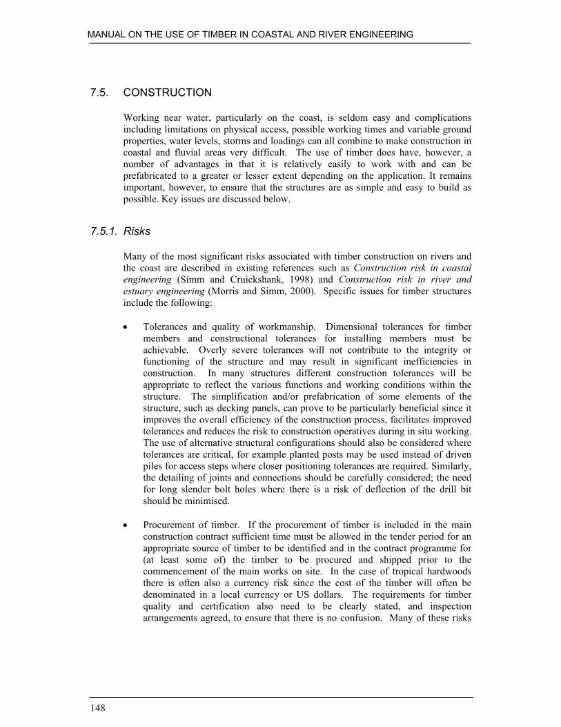
MANUAL ON THE USE OF TIMBER IN COASTAL AND RIVER ENGINEERING
148
7.5. CONSTRUCTION
Working near water, particularly on the coast, is seldom easy and complicationsincluding limitations on physical access, possible working times and variable groundproperties, water levels, storms and loadings can all combine to make construction incoastal and fluvial areas very difficult. The use of timber does have, however, anumber of advantages in that it is relatively easily to work with and can beprefabricated to a greater or lesser extent depending on the application. It remainsimportant, however, to ensure that the structures are as simple and easy to build aspossible. Key issues are discussed below.
7.5.1. Risks
Many of the most significant risks associated with timber construction on rivers andthe coast are described in existing references such as Construction risk in coastalengineering (Simm and Cruickshank, 1998) and Construction risk in river andestuary engineering (Morris and Simm, 2000). Specific issues for timber structuresinclude the following:
• Tolerances and quality of workmanship. Dimensional tolerances for timbermembers and constructional tolerances for installing members must beachievable. Overly severe tolerances will not contribute to the integrity orfunctioning of the structure and may result in significant inefficiencies inconstruction. In many structures different construction tolerances will beappropriate to reflect the various functions and working conditions within thestructure. The simplification and/or prefabrication of some elements of thestructure, such as decking panels, can prove to be particularly beneficial since itimproves the overall efficiency of the construction process, facilitates improvedtolerances and reduces the risk to construction operatives during in situ working.The use of alternative structural configurations should also be considered wheretolerances are critical, for example planted posts may be used instead of drivenpiles for access steps where closer positioning tolerances are required. Similarly,the detailing of joints and connections should be carefully considered; the needfor long slender bolt holes where there is a risk of deflection of the drill bitshould be minimised.
• Procurement of timber. If the procurement of timber is included in the mainconstruction contract sufficient time must be allowed in the tender period for anappropriate source of timber to be identified and in the contract programme for(at least some of) the timber to be procured and shipped prior to thecommencement of the main works on site. In the case of tropical hardwoodsthere is often also a currency risk since the cost of the timber will often bedenominated in a local currency or US dollars. The requirements for timberquality and certification also need to be clearly stated, and inspectionarrangements agreed, to ensure that there is no confusion. Many of these risks

DESIGN AND CONSTRUCTION ISSUES
149
can be borne more easily by the client than contractor and direct procurement oftimber is often appropriate.
• Wastage and timber quantities. Contractors will need to allow for waste(including cutting, squaring and dimensional waste) when tendering for aproject. This is simplified if information on all elements of the structure(including, for example, a schedule of plank sizes for a groyne) is provided bythe designers. Short contract periods can significantly increase the proportion ofwastage as the availability of ‘stock timber’ is limited and the particular sectionsize and length required may not be readily available.
• Use of chemicals and preservatives. Particular care is required in the use ofchemicals and preservative treatments, both to ensure that the site does notbecome contaminated and that the operative is adequately protected. Surplusmaterials should be disposed of in accordance with the manufacturer’s guidance.
7.5.2. Plant, tools and techniques
The construction of timber coastal and river structures requires the use of a range ofdifferent types of plant and equipment, much of which needs to be operated with careto ensure that it is safe and efficient. Specific considerations are provided below.
• Plant. Many contractors used adapted and/or oversized plant for fluvial andparticularly coastal works, in recognition of the greater reliability and rates ofproduction that this can afford. Plant should be regularly maintained andoperated in accordance with safe working practices.
• Handling timber. Suitable information and appropriate Personal ProtectiveEquipment should be provided to all operatives coming into contact with timber.When tropical hardwoods are being used this will usually include a briefing onthe dangers of splinters and use of good quality working gloves and overalls toreduce this danger. The density of many tropical hardwoods is such that it isonly possible for very small sections to be lifted manually, and appropriate plantand equipment should be provided to allow for safe handling of timber includingany prefabricated components (see Section 7.4.2).
• Air tools such as augers and wrenches driven by compressors are often used incoastal and river construction projects. These are often safer and more reliablethan electrical alternatives in the hostile environment, although the use ofhydraulic tools driven by diesel power packs may also be appropriate. Regularmaintenance (on at least a weekly basis) is required for both the tools and thecompressor. Attention should also be paid to the air hoses and a vessel to collectmoisture should be provided on the compressor. Oil or antifreeze can also beintroduced into the airlines to reduce moisture and prevent freezing in coldweather.

MANUAL ON THE USE OF TIMBER IN COASTAL AND RIVER ENGINEERING
150
• Chainsaws. Cutting and shaping of timber is often undertaken using chainsaws,which are available in a number of sizes and with a variety of chains. Careshould be taken to ensure that the saw used is appropriate to the job. Chains willrequire regular sharpening, particularly when used with tropical hardwoods andall operatives should be adequately trained and supervised in the use and care ofthe saw. Full Personal Protective Equipment, including a helmet with a fullmesh mask, ear defenders, chain mail leggings, bib and gauntlets as well as steellined safety boots will be needed by operatives using chainsaws.
• Hand tools. Tools such as the adze have been used for hundreds of years, andare still widely used for shaping of timber, including the ‘topping and tailing’ ofpiles in preparation for rings and shoes. The use of an adze requiresconsiderable skill and training/supervision of novices by experienced operativesis essential. Suitable personal protective equipment including eye, hand and footprotection should be worn.
• Construction techniques. Consideration should be given to the weight and safeoperation of all tools when developing the construction methodology. Manytools are heavy (for example a large auger might weigh 13 kg) and unwieldy tooperate (note the length of the auger required to drill through two pieces oftimber in Figure 7.10) which will reduce productivity during construction.Opportunities for full or partial prefabrication should be identified wherepossible as this can provide significant savings. Provision of safe access to thestructure should also be considered – scaffolding is seldom practical incoastal/river locations, but bunds of beach or other materials may be usedsuccessfully. Appropriate clothing and/or lifejacket should be provided tooperatives working in or close to the water: care should be taken to ensure thatthese are not so bulky as to increase the danger or cause a reluctance to wearthem.

DESIGN AND CONSTRUCTION ISSUES
151
Figure 7.10. Fitting ties to a pile for a timber groyne (courtesy MackleyConstruction)
7.5.3. Maintenance
The maintenance of timber structures is often critical to their long term performance,and care should be taken to ensure that maintenance operations can be undertakeneasily and safely. Particular issues to consider with respect to the maintenance oftimber structures include:
• Members, such as cladding or planking which may need replacing within thelifespan of the structure, should be relatively easy to access and disconnect

MANUAL ON THE USE OF TIMBER IN COASTAL AND RIVER ENGINEERING
152
(fixings should be accessible and the need to remove other members should beavoided).
• Allowance should be made where reasonably possible for adding new primaryand secondary members within the scope of the structure at a later date.
• Safe access to the structure for maintenance should be considered during thedesign and construction process, and measures incorporated into the structurewhere appropriate.
• Consistent sizes of materials and fixings should be used as far as possible tolimit the range of materials held in stock and tools, etc. used on site.
• Regular monitoring should be undertaken (see Chapter 9) to enable the need formaintenance works to be identified as early as possible and minimisedeterioration.
7.6. PILES AND FOUNDATIONS
Piles frequently form the primary members of many coastal and timber structures,and as such they are essential for structural integrity and the most difficult to replaceif damaged or broken. It is essential therefore that the correct material is selected forthe pile and that it is not damaged during construction. Particular attention should bepaid to detailing to ensure appropriate durability, and monitoring should beundertaken to ensure there is no excessive wear. Pile caps should be used wherepossible to prevent the top of the pile deteriorating.
7.6.1. Timber as a pile material
The advantages of timber as a pile material are that it is generally less expensive thanother materials and that it is more easily trimmed to length and is therefore morereadily adapted to variable ground conditions. It is considered to be moreenvironmentally ‘friendly’ being a natural material. In certain circumstances timberpiles have a working life equal or better than steel or concrete (e.g. when subject toshingle abrasion). In general, the durability of the embedded pile is good belowgroundwater level but above this level timber may be exposed to biological attack byfungi and/or marine borers, depending on service conditions.
The lightweight, flexibility and handling characteristics of timber piles are suitedto the construction of groynes, river walls and small jetties and walkways, providingadequate preservative treatment is given to timber species vulnerable to decay.
Timber selected for piles should be free from defects, which may affect theirstrength and durability. It is important that piles have a straight grain particularlywhere hard driving is anticipated. The centreline of a sawn pile should not deviate bymore than 25 mm throughout its length, however for a round pile a deviation of up to25 mm on a 6 m chord may be permitted.
In the United Kingdom greenheart is the most commonly used hardwood timberfor piles, while Douglas fir and pitch pine are commonly used for softwood piles.

DESIGN AND CONSTRUCTION ISSUES
153
7.6.2. Pile design considerations
The working stresses expected to be encountered, both in use and during pileinstallation, should be calculated and checked to ensure that the permissible stress asfound from BS 5268-2: 2002 is not exceeded for compression parallel to the grain forthe species and grade of timber. Any loss of section due to drilling or notching mustbe allowed for in the calculation. Very much larger stresses are normally developedduring pile driving.
There is a tendency for timber fibres to separate (broom) at both the head and toeof the pile during heavy driving. Cracking results, causing loss of structural strengthand reducing the effect of preservative treatment.
Piles should be ordered in sufficiently long lengths that, after driving, they canbe cut off square at the required level with the top left clean and undamaged. Thesquared head should be cut off to sound timber and treated with preservative whereappropriate before capping.
It is recommended that where untreated softwood piles are used for thepermanent foundation of a structure they should be cut off below the lowestanticipated groundwater level. They should then be extended if necessary using moredurable material such as concrete. Where concrete caps are used for extending thepiles they should be embedded for a sufficient depth to ensure transmission of theload. Concrete should be reinforced and at least 150 mm thick around the piles.
7.6.3. Driving procedure
Timber piles absorb energy and require larger hammers than equivalent concrete orsteel piles; they are relatively easy to handle and can be driven either by using simpletrestle frames and drop hammers or with more sophisticated equipment. There ishowever the danger that the pile head will broom and the pile toe crush under heavydriving. The likelihood of these problems occurring can be reduced by limiting thedrop and number of blows of the hammer. A driving cap or ‘dolly’ should be usedwhen driving. In addition, pile heads can be tapered and steel rings and shoes fittedto reduce damage. Shoes should be concentric and firmly attached to the end of thepile, the contact area between shoe and timber being sufficient to avoid overstressingduring the driving operation (Figure 7.11). It is recommended in BS 8004: 1986Code of practice for foundations, that it is desirable that the weight of the hammershould be equal to the weight of the pile for hard driving conditions and not less thanhalf the weight of the pile for easy driving. The working loads on timber piles areoften limited to about 300 kN on a 300 mm × 300 mm pile to reduce the need forexcessively hard driving. Unnecessary high pile driving stresses can be avoided byensuring that the pile head is central with the hammer and normal to the length of thepile. A pile should not be allowed to run out of position relative to the leader.
Piling equipment should incorporate robust gates or leaders to ensure accuratepile positioning and to eliminate twist when driving. Tolerances need to be tightperpendicular to the centre line of the groynes or similar structures to ensure a tightbearing surface for the planks and walings. They may be relaxed somewhat parallelto the centre line unless there are fixings in that plane. Suggested tolerances are10 mm and 100 mm respectively.
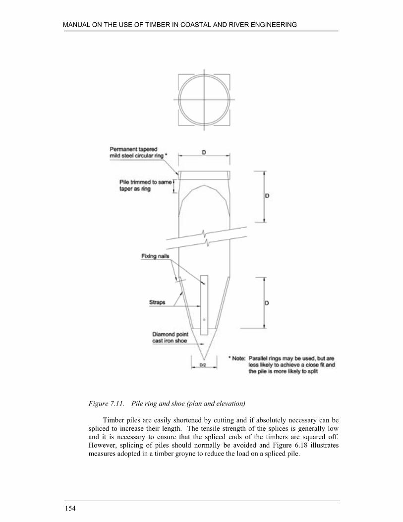
MANUAL ON THE USE OF TIMBER IN COASTAL AND RIVER ENGINEERING
154
Figure 7.11. Pile ring and shoe (plan and elevation)
Timber piles are easily shortened by cutting and if absolutely necessary can bespliced to increase their length. The tensile strength of the splices is generally lowand it is necessary to ensure that the spliced ends of the timbers are squared off.However, splicing of piles should normally be avoided and Figure 6.18 illustratesmeasures adopted in a timber groyne to reduce the load on a spliced pile.

155
8. Structure specific guidance
The detailed design and quality of construction of timber structures can have asignificant impact on their performance and durability, but these are frequently onlyappropriate on a limited range of structures. Thus, whilst the general principles andissues have been described in the previous two chapters, the following sections dealwith those of specific relevance to the various different structures. In each case therelevant issues are discussed in the following order:
• choice of timber structure• operating conditions• timber species• overall configuration• overall stability• members and connections• details• finishes and fittings• maintenance.
References to relevant literature or other sources of information are also providedwhere available. It should be remembered, however, that the design of any structuremust include consideration and analysis of its particular functional requirements,situation and conditions. This analysis must be undertaken by competent individualsor organisations and the experience available from specialist consulting engineers isoften valuable.
8.1. GROYNES
Traditionally, timber groynes in the UK have been impermeable vertical structuresconstructed more or less perpendicular to the shore- or bank-line to restrict themovement of sediment. They are used on the open coast to retain beaches and withinrivers and estuaries to control the flow and sedimentation regimes. Conventionalgroynes usually work by fulfilling one or both of the following functions:

MANUAL ON THE USE OF TIMBER IN COASTAL AND RIVER ENGINEERING
156
• Providing a physical barrier to the movement of the beach material, enabling thebeach within the groyne bay to reorientate approximately perpendicular to theincident wave direction.
• Reducing or diverting currents away from the beach or river bank.
It must be noted that groynes do not prevent cross-shore transport of sediment onbeaches and often only interrupt the longshore drift, transferring the erosion problemdown-drift of the groyne field if designed in isolation. Coastal groynes do not usuallycontribute to the primary function of coast protection or sea defence schemes (thereduction in wave energy reaching the backshore area), but retain and sometimesbuild-up the beach, which thus provides protection by absorbing part of the incidentwave energy.
A variety of permeable timber groynes has also been used. These range fromround logs placed vertically, with the spacing varied to alter permeability, to rathermore complex structures constructed from sawn timber, with either a straight, orzigzag plan shape.
8.1.1. Choice of timber structure
The other main construction materials for groynes are rock, masonry and concrete.Steel may also be a significant component when used in conjunction with othermaterials. The choice of material for a particular situation depends upon technical,environmental and economic considerations.
Timber is probably the most technically versatile of the materials. It has thepotential to provide the best balance in terms of strength, size, durability, workabilityand buildability. At the design and construction stages it is easily adapted to thesituation and during the service life of the structure it lends itself to modifications(e.g. raising or lowering of planking heights) and to maintenance (e.g. replacement ofdefective planks). Whilst other materials may perform better in certain areas (e.g.rock is more durable) they are likely to be less effective in others.
Environmentally, timber has a number of benefits. A timber groyne usuallytakes up less space than its equivalent in other materials and in an amenity situation isoften more compatible with its surroundings. Where space and aesthetics are lesscritical, other materials may have the advantage.
Economically, timber structures may have lower capital but higher maintenancecosts, which can include periodic replacement. Comparison with other materials hasto be made on a whole life basis and durability is often a key factor in thisconsideration.
8.1.2. Operating conditions
Timber groynes can be used in most coastal locations where it is considered feasibleto retain a beach, and there are many examples of the successful application ofgroynes on different types (including both sand and shingle) of beaches. Rockstructures, or heads, may be preferred on beaches with a high wave energy as they areless reflective and reduce scour at the tips of the groynes. Similarly, although timber

STRUCTURE SPECIFIC GUIDANCE
157
piles can be excavated and planted into hard substrate, other forms of constructionmay be more practicable in these situations.
Coastal groynes will normally be subject to considerable abrasion from mobilebeach material and are often also exposed to marine borers below the mean waterlevel. They should be designed to resist wave loading and appropriate differentialbeach levels across the structure. Safety of beach users will need to be consideredduring the design and detailing of the structure, and groyne markers are oftenrequired to assist both small craft and swimmers.
The operating conditions for river groynes will usually be much less onerousthan those for coastal groynes, although estuarine locations may still be subject tosome wave loading and/or marine borer attack. The provision of adequate navigationmarks is particularly important to prevent damage to or from river groynes.
8.1.3. Timber species
The requirements for strength and resistance against both abrasion and marine borerslimits the selection of timber species for many coastal groynes to tropical hardwoods,most commonly greenheart or ekki, however other species such as balau and kapurhave also been used with some success. Temperate hardwoods such as oak andsoftwoods such as pitch pine or Douglas fir have also been used, but are less durableand more susceptible (unless preservative-treated) to attack by marine borers.
The selection of appropriate timber will be dependent on environmentalconstraints as well as the exposure and required working life for the structure. Insome cases, different species may be used for different components (e.g. tropicalhardwood piles and walings and softwood planks) or exposures (above/below normalbeach or water level) but this can make procurement difficult and complicateconstruction. Construction of groyne fields may require particularly large quantitiesof materials, necessitating a significant procurement period and good co-ordination tomatch the timber supply to the progress of the works.
8.1.4. Overall configuration
The overall configuration of a particular groyne or groyne field (Figure 8.1) isdependent on the characteristics of the beach (including the type and grading of thebeach material) as well as the wave, wind and current exposure which will all affectthe beach profile and rate of transport. Guidance on the design profile of groynes isavailable from a number of sources including CIRIA (1996), Fleming (1990) andUSACE (1992). Most schemes will be optimised using physical and/or numericalmodels. However, it should be noted that the models and expected loadings includeinherent uncertainties, and provision within the design to vary the profile by addingor removing one or more planks can be very valuable.
Some of the different options relating to the configuration of timber groynes areillustrated in the following sections.
MANUAL ON THE USE OF TIMBER IN COASTAL AND RIVER ENGINEERING
158
Conventional groynesConventional impermeable groynes are constructed from sawn timbers includingsquare vertical piles, planking (normally on the up-drift side) and often one or morehorizontal or sloping walings to distribute loading between the piles. Planking ortimber sheet piles are often continued some distance below the beach level to providepassive resistance against ground and wave forces. In some cases, props or ties (seeSection 6.5) will be needed to provide stability, although they can suffer fromextensive abrasion and the use of double piles may also be considered. Conventionalimpermeable groynes reflect waves, and may focus longshore currents at the tip ofthe groyne, both of which can lead to scour.
Figure 8.1. Conventional impermeable timber groyne field (courtesy Arun DistrictCouncil)
Permeable groynesPermeable groynes are designed to allow beach material to pass through them but at aslower rate than would otherwise be the case for an open beach. In practice it is verydifficult to achieve this, especially with narrow structures. The driving forces for thelongshore movement of beach material can often dominate the structure, resulting invery little net effect upon overall beach levels: also, the passage of beach materialthrough the structure can cause severe abrasion of the timbers.
The use of permeable groynes, instead of more conventional impermeablegroynes, is usually with a view to reducing their impact upon longshore movement ofbeach material and the potential for realignment of the coast down-drift of thegroynes. The use of lower and/or shorter conventional groynes can have the sameend result. However, with careful design and in selected situations, including thosewith lower energy regimes, permeable groynes have a role to play. Additionally,

STRUCTURE SPECIFIC GUIDANCE
159
such structures can be combined with other concepts, such as zigzag shapes, toimprove their performance.
Permeable groynes may be used on beaches, but are widely perceived to functionbest in locations where there is a current but minimal waves, particularly rivers. Theyoften consist of single or double rows of round timber piles driven into the underlyingstrata (Figure 8.2). The use of round piles minimises wastage but it should beremembered that such materials will be susceptible to marine borers if temperatetimber is used or sapwood is not removed. The spacing between the piles and level ofthe piles above the bed or beach will depend on the intended influence of the groyne,but whilst the spacing is often approximately equal to the diameter of the pile, noestablished relationships are available for design purposes.
Permeable groynes constructed from sawn timbers have been used at a numberof locations around the British coast but anecdotal evidence suggests that theireffectiveness and durability is poor compared to conventional impermeablestructures.
Figure 8.2. Pile groyne at Ameland, The Netherlands (courtesy HR Wallingford)
Zigzag-shaped groyneThe main purpose of a zigzag shape is to prevent waves or currents running parallelwith the structure and causing scour. The shape also increases the effective width ofthe groyne which can further reduce the possibility of down-drift scour whilstproviding the structure with inherent stability; detailing can be more difficult.
When a zigzag configuration is combined with a permeable construction, thebeach material partially trapped within the zigzags can act as a further filter mediumin conjunction with the structure itself.
GeometryThere is a range of different groyne concepts, which provide appropriate solutions inparticular locations. One example, illustrated in Figure 8.3, uses a combination ofrecycled and local timber to construct zigzag shaped groynes. Although thesestructures have a limited life and high maintenance commitments, their low capital

MANUAL ON THE USE OF TIMBER IN COASTAL AND RIVER ENGINEERING
160
cost makes them an attractive option in some situations. If new tropical hardwoodsare used, initial costs will be higher, but they should require less maintenance.
Figure 8.3. Low cost groyne, Calshot, Hampshire (courtesy HR Wallingford)
A variety of other types of groyne has also been used. For example, plank pilegroynes consisting of two plank pile walls with ties between the piles and the spacebetween them filled with sand, gravel, earth or stone. These structures may be usedas small breakwaters and where they are overtopped rubble is placed as a top layer toprevent the finer material washing out. Other examples include the use of a singletongue and groove plank pile wall supported by sawn timber walings and round piles.The form and geometry of the groyne will need to be optimised for the material usedand the loadings occurring at the particular location.
Overall stability of structureThe overall stability of the structure will need to consider wave loadings and largedifferences in beach levels across the structure. The techniques described in Section6.5 are generally appropriate for groynes and the technique adopted for any particularstructure is largely a function of the ground conditions at the location.
Members and connectionsSince groynes are heavily loaded and often constructed in difficult workingconditions, the key to successful design of members and connections is keeping thestructure arrangement simple with as few connections as possible. Prefabrication ofelements such as panels of sheet piles, fixed near or below low water, can increasesafety and improve the quality of construction. Much useful information on membersand connections is given in Sections 6.5 and 6.6.

STRUCTURE SPECIFIC GUIDANCE
161
Preservative-treated timbers are not usually used in groynes due to the highpropensity for abrasion, which could quickly strip the preservative protected outerlayer of the timber leaving the remaining timber exposed to biological attack as well.
Finishes and fittingsAll fixings on groynes (see Box 8.1) are exposed to severe wear and oxidation, due tothe aggressive marine environment. Therefore as few bolts as possible should be usedand never placed in the same grain line of the timber. Galvanised steel fixings arecommonly used but stainless steel fixings have the advantage that the groyne can bedismantled or refurbished more easily and the fixings can be reused.
As with the arrangement of members and connections, finishes and fittingsshould be kept as simple as possible and as few as possible.
Box 8.1. Groyne fixingsBournemouth Borough Council started building timber groynes in 1971. Aluminiumbronze bolts were used at first but large numbers were stolen because of their highscrap value. Stainless steel became the preferred option in 1973, because of itsresistance to corrosion and abrasion, and its relatively low scrap value. Lock nutswere essential to stop the nuts from loosening, but some managed to anyway.
Around 5% of the new bolts were unusable because of thread damage, presumedto have been incurred during transport and handling. Furthermore, grit in the threadscaused nuts to lock up, giving additional wastage. However, when groynes were rebuiltafter 25 years service, the nuts could often be undone, with potential for reuse.
Drilling holes for long bolts is a critical operation as 1mm clearance only isdesirable to limit component sag, so good quality bits are essential. Long drill bitsare flexible and can wander, which means that a sledgehammer is needed to drive thebolts home. This adds to fixing time, and is not good for the bolt.
Risk assessments indicated that protruding bolt threads were undesirable so, in1999, coach screws were considered. As part of the assessment of the potential, thecurrent contractor (Dean & Dyball) tried using tungsten carbide tipped bits to getmaximum accuracy when hole drilling, and conducted pull-out tests using newgreenheart baulks. These were impressive. The stainless steel coach screws failed bystretching before the threads pulled out. As a result, all subsequent groynes werebuilt using coach screws wherever possible.
Three years’ experience shows that coach screws have the following advantagesover bolts:
• they are cheaper• they are not susceptible to thread damage• they can be fixed from one side of the groyne only, reducing excavation and
labour requirements• they are less of a danger to beach users• they can be done up tighter than bolts• hole length, and hence drilling time, is reduced• there is no risk of the drill bit going right through the timber and producing
splinters.

MANUAL ON THE USE OF TIMBER IN COASTAL AND RIVER ENGINEERING
162
MaintenanceMaintenance is critical to the effective performance of timber groynes and can rangefrom removing the top plank if beach levels have fallen (to reduce wave reflectionsfrom the structure) to replacing life-expired piles or increasing the level of plankingon a groyne by adding pile extensions.
AbrasionTo protect piles from abrasion as shown in Figure 8.4a, softwood or recycled timberrubbing pieces can be attached to the piles at critical levels (Figure 8.4b). Extendingplanks beyond piles may also reduce wear, increasing the life of the primary andsecondary members. Members should be sized with an allowance for wear and theconnections carefully chosen. On some sand beaches ply panels have been fixed tothe groynes preventing sand being transported between the planks and thusminimising abrasion, which increases dramatically with the size of the gap.Maintenance will require regular inspection of the structures and replacing of wornrubbing pieces.
AdaptabilityGroynes should be adjusted to the optimal height, matched to the changing beachprofile, possibly several times throughout their lifetime. In some cases, extending partor all of a groyne to the preferred height may be an attractive solution instead ofrebuilding an entire groyne. However, when constructing a groyne, an allowance maybe provided in the pile length for extra planking. See Figure 8.5 and also note the‘shaped’ planks at the interface of the old and new sections of planking which wereused to adjust the profile of planking to match the extended piles.
Figure 8.4a. Abraded timber groyne pile (courtesy HR Wallingford)

STRUCTURE SPECIFIC GUIDANCE
163
Figure 8.4b. Rubbing pieces protecting the pile on a timber groyne (courtesyHR Wallingford)
Figure 8.5. Pile extensions to facilitate reprofiling of a groyne field (courtesy ArunDistrict Council)

MANUAL ON THE USE OF TIMBER IN COASTAL AND RIVER ENGINEERING
164
Reprofiling can be carried out gradually, i.e. a few planks at a time to encouragenatural accretion, or in one operation in conjunction with beach nourishment.
ConstructionAs groynes are generally built using land-based plant, special attention should be paidto constructing the seaward end of the groyne as the tidal window may be verylimited.
LiteratureCIRIA (1996). Beach management manual. Simm, J.D., Brampton, A.H., Beech,
N.W., and Brooke, J.S. Construction Industry Research and DevelopmentAssociation, Report 153.
Fleming, C.A. (1990). Guide on the uses of groynes in coastal engineering.Construction Industry Research and Information Association, Report 119,London.
USACE (1992). Coastal groins and nearshore breakwaters. US Army Corps ofEngineers, Engineer Manual 1110-2-1617, Aug.
8.2. DUNE PROTECTION, BREASTWORKS AND REVETMENTS
8.2.1. Dune protection
Several techniques have traditionally been used to protect, stabilise or restore dunes,often using timber or brushwood cuttings. It should be remembered that vegetatedsand is the best protection, and the aim of stabilising dunes. Dune or sand fences(Figure 8.6), placed parallel to the shore reduce wind speed across the sand surfaceand thus encourage the deposition of wind-blown sand. Further the fences will helpprotect existing or planted vegetation by stabilising the surface and reducingtrampling. Another use of sand fencing is to keep roads or paths leading through thedunes free of drifting sand.
Timber fences may be constructed as barrier fencing at the base of a dune(Figure 8.7), protecting it from erosion due to occasional wave attack. Sand movesonshore with low waves and offshore when high waves attack the shore duringstorms. Protecting dunes against storm waves is an effective method to decreaseerosion. The most common type of wave barrier fencing is known as a Dutch fence,constructed of brushwood or chestnut paling in a rectangular shape at the toe of thedune. More solid structures can be built for the same purpose, including vertical orsloped permeable revetments. Wave barrier fencing should always be built above thelimit of normal wave run-up to avoid undermining.
Laying a thatch of brushwood over the surface of the sand and planting marramgrass or sowing grass seeds in the gaps can help recover areas with no or little supplyof sand. If willow and poplar species are used, the thatching can be dug into the sandto encourage growth from the cut stem.

STRUCTURE SPECIFIC GUIDANCE
165
Dunes are often stabilised or restored in a management scheme of dune grassplanting, thatching, fencing and beach nourishment.
Figure 8.6. Dune fencing, Greatstone on Sea, Kent (courtesy HR Wallingford)
Figure 8.7. Dune barriers at Pwllheli, Gwynedd (courtesy Posford Haskoning)
Choice of timber structureAs natural materials, timber and brushwood are more appreciated aesthetically thansynthetic materials. Sand fencing can best be constructed using biodegradable

MANUAL ON THE USE OF TIMBER IN COASTAL AND RIVER ENGINEERING
166
materials, as the fences often will become buried if successful or be washed away ifnot. For the same reason it is preferable to use low-cost materials such as brushwood.However, fencing is usually constructed using long lasting wire which may become ahazard in the longer term. Although natural materials are preferred, synthetic snowfencing has successfully been used for dune fencing and its use may be considered insome cases.
The labour costs for dune management schemes can be considerable although, inmany cases, conservation volunteers may carry out the necessary maintenance, as thedunes are often of high ecological value. Straw bales are successfully used to repairsmall blowouts.
Operating conditionsDune fencing, wave barrier fencing and thatching will resist some erosion, but cannotprevent erosion where wave attack is continuous and damaging. Where wave attackdoes occur regularly, it may be necessary to place substantial timber piles to avoidannual reconstruction. To prevent rotational failure support piles must be buriedadequately, as beach levels will drop during storms.
Wave barrier fencing, placed just in front of a dune helps prevent severe damagecaused by storm wave attack. The rectangular-shaped Dutch fences have two lines ofbrushwood, the outer acting as the main barrier against waves and the innerprotecting the dune base. Both dune fencing and wave barrier fencing may beremoved for part of the year on high amenity value beaches. However, this method isnot recommended as the extra work may damage the dunes and the fences may not bebeneficial at all in the end. To reduce the amount of work on temporary fences,permanent posts can be erected, to which the fencing is attached seasonally. A slopedtimber revetment as a wave barrier fence will suffer less toe scour than a verticalwall, but cannot resist continuous wave attack either.
Public access routes must be built in to the design of dune retaining structures,especially on popular public beaches to prevent the public from damaging fences tocreate their own paths. The tracks should follow the natural contours of the dunes asmuch as possible. In popular areas fences should be designed to be as vandalism-resistant as possible, e.g. with secure fixings. Dune fencing adjacent to paths willstabilise the sand and prevent trampling of the dunes.
Timber speciesThe choice of materials for dune fencing or thatching will depend on required life,length of the frontage, level of maintenance and potential for vandalism. Beach usersoften remove thatching and fencing materials for bonfires. Fencing materials includechestnut palings, pine, birch, wooden slats or synthetic fabrics. Brushwood can bemade-up of a number of different species, e.g. local sea buckthorn or conifertrimmings. Locally available timber offcuts can be used but may result in beinghazardous, as they are likely to generate splinters and loose staples.
Sea buckthorn is likely to spread uncontrollably if the branches are not dead orstill have berries on them.
Wooden slat fences are not recommended, as they are relatively expensive toconstruct and often are stolen by beach users. Wooden slats tend to deflect the wind,causing erosion whereas brushwood traps sand because of its filtering action.

STRUCTURE SPECIFIC GUIDANCE
167
Posts and wave barrier revetments can be constructed from treated softwoods orin some cases hardwood, possibly recycled, as the lengths required are short. Railwaysleepers may be used to create vertical wave barrier fencing in more vulnerable areas,acting more like a sea wall rather than fencing.
Overall configurationBrushwood fencing and chestnut paling are the two most common fence types.Brushwood fencing is an upright hedge of stacked brushwood whereas chestnutpaling is constructed using support posts and tensioning wires.
Fencing should be aligned parallel to the dune face, forward of the toe of thedunes, although in some cases the fencing is set-up at right angles to the prevailingwind. Posts and wires are best set-up to last for several years as they are costly toreplace. The posts should be long enough to ensure the stability of the fence at thelowest expected beach level. Sand will build up 1.25 m leeward of the fence (Ecopro,1996). Initially fences should be constructed at the downward end of where the build-up is required. When the sand level has increased, additional lines of fencing can beadded, spaced at a distance of four times the height of the fence (Ecopro, 1996).
Short spurs may be constructed up a dune, spaced at six times the fence height(Ecopro, 1996), at areas subject to local erosion to restore that specific part of thedune. Spurs running seaward are less useful and may be damaged by swash zonedebris or by beach users trying to walk along the shore at high tide.
A porosity of 30% to 50% is required for dune fencing to be effective (ScottishNatural Heritage (SNH), 2002). Standard paling fences of the type used aroundconstruction sites have a porosity larger than 50% and should therefore not be usedfor dune management.
Wave barrier fencingConstructing wave barrier fencing may generally be the same as dune fencing, otherthan the rectangular layout of the wave barrier. Dutch fences are constructed usingbrushwood and arranged in the form of a rectangle. Trenches are dug at the toe of thedune in which the brushwood is placed upright. The primary function of wave barrierfencing is to absorb wave energy, but they will encourage sand build-up too.
Dune thatchingThatching should cover 20 to 30% of the sand surface (SNH, 2002) and be laid abovethe line of normal wave run-up. Biodegradable mats can be used for the same purposebut are more likely to be damaged in the marine environment. Dune thatching ormatting should always be complemented with the planting of marram grass or sowingof grass seeds in the gaps or in holes. It is recommended not to use thatching onslopes steeper than 1:2. In these cases the dunes will have to be reshaped orrenourished to obtain the required dune profile.
MaintenanceRegular maintenance is required for both fencing and thatching, and repairs should becarried out as soon as possible. Maintenance can be carried out during the whole year,but planting of marram grass is preferably done in spring. When planning

MANUAL ON THE USE OF TIMBER IN COASTAL AND RIVER ENGINEERING
168
maintenance, nesting and migration of birds, public access and safety should be takeninto account. Damage on thatching should be repaired as soon as possible.
Dune fencing may catch blown litter.
LiteratureBrookes, A. and Agate, E. (2000). Sand Dunes: a practical handbook. British Trust
for Conservation Volunteers.http://handbooks.btcv.org.uk/handbooks/index/book/137
Scottish Natural Heritage (2002). A guide to managing coastal erosion in beach/dunesystems. http://www.snh.org.uk/pdfs/publics/catalogue/nhm.pdf
Searle, S.A. (1975). The tidal threat. Dunes Group, UK. ISBN 0950400106.
8.2.2. Breastworks and revetments
Seawalls, revetments and breastwork are generally positioned at or slightly landwardof the crest of the beach aligned parallel to the shoreline. They are normally intendedto provide protection against erosion or breaching of the beach during severe eventsand often take a similar structural form to groynes. Breastwork is often used as asecondary defence at the back of a groyned beach.
Choice of timber structureShore parallel structures may be constructed from a wide range of materials includingsteel sheet piling, rock armour and concrete. Timber has the advantage (along withsteel and, to a lesser extent, concrete) that it can be used in a vertical structural form,reducing the volume of material required and minimising the area of beach occupied.Such vertical forms will result, however, in the reflection of incident wave energy andis likely to increase erosion of the beach.
Where dunes or a shingle ridge are located behind the beach the use ofimpermeable breastworks or seawalls will severely disrupt interchange of material toand from the beach, limiting the ability of the natural system to roll back and adapt tochanges in loading.
Operating conditionsSeawalls and breastwork should be designed to withstand the full force of waveimpacts and to accommodate any expected beach level changes due to erosion and/orscour. The term ‘bulkheads’ (Figure 8.8) is often used to refer to structures primarilyintended to retain fill and generally not exposed to significant wave action. Typically,revetments are lighter, permeable structures allowing some movement of beachmaterial through the structure.

STRUCTURE SPECIFIC GUIDANCE
169
Figure 8.8. Timber bulkhead with rock toe protection at Lepe, Hampshire (courtesyHR Wallingford)
Timber speciesConventional impermeable breastwork has traditionally been constructed fromsimilar materials to conventional groynes – including tropical hardwoods. However,where the structure is located landward of the high water level the susceptibility toattack by marine borers will be significantly reduced (even if the water tablepermeates through the beach) and less durable timbers (such as oak) may be used.Temporary or low-cost structures may be constructed using round piles, or acombination of treated softwood posts and geotextiles.
The selection of material will depend to a significant extent on the likelihood ofattack by marine borers and the degree to which the structure will need to resistabrasion from beach materials.
Overall configurationMost timber breastworks/bulkheads are impermeable vertical walls, which will reflectany waves reaching the structure. Such structures are unlikely to be appropriate inareas of very high wave energy, or where there is no beach in front of the structure.
Conventional breastworkThe construction of conventional breastwork is shown in Figure 8.9 and a completedbreastwork at Pevensey, East Sussex in Figure 8.10. The configuration is verysimilar to a conventional timber groyne, with piles driven into the beach and plankingor plank piles used to provide passive resistance.

MANUAL ON THE USE OF TIMBER IN COASTAL AND RIVER ENGINEERING
170
Figure 8.9. Construction of a timber breastwork (courtesy Mackley Construction)
Figure 8.10. Breastwork at Pevensey, East Sussex, retaining substantial shinglebeach, to right of photo (courtesy Aitken & Howard Ltd.)

STRUCTURE SPECIFIC GUIDANCE
171
An example of a vertical permeable breastwork at Shoreham, West Sussex isshown in Figure 8.11. This solution is not very common and has the disadvantagethat the individual vertical piles do not wear well.
Figure 8.11. Vertical breastwork at Shoreham, West Sussex (courtesy ShorehamPort Authority)
Permeable revetmentAn example of a permeable sloping revetment is illustrated in Figure 8.12. Thesestructures were used extensively to protect soft cliffs on the east coast of England, butare widely regarded to be of only limited effectiveness; many lengths have now beenreplaced by rock armour revetment. In some locations the timber framework is usedto secure smaller rock armour that would otherwise move under the force of waves asin a gabion or crib work structure.
Permeable revetments reduce the reflection of wave energy, limiting scourproblems at the toe of the structure, and allow the cross-shore movement of material.However, the structures may limit access to the foreshore (note the steps over thestructure in Figure 8.12) and have are susceptible to damage and difficult to maintain.

MANUAL ON THE USE OF TIMBER IN COASTAL AND RIVER ENGINEERING
172
Figure 8.12. Permeable sloping ‘Mobbs and English’ revetment (courtesyHR Wallingford)
Low cost structuresIn some locations lower cost structures have been constructed using softwood timberposts and geotextiles (see, for example, Figure 8.13). These are normally unable towithstand larger wave forces or have limited service life but may provide areasonable standard of protection in locations with low wave exposure.
Figure 8.13. Low cost revetment with geotextile at Calshot, Kent (courtesyHR Wallingford)

STRUCTURE SPECIFIC GUIDANCE
173
Overall stabilityScour of the foreshore due to wave reflections is the largest problem with seawallsand revetments. As scour increases, so does the water depth, allowing higher wavesto reach the wall and thus eventually undermining the foundations and causingcollapse. Sheet piling, together with bed protection such as matting and rock armourat the toe of the structure, is often used to protect against this failure mechanism.
Seawalls or revetments disturb the natural longshore drift of sediment and mightresult in extra erosion at the down-drift end of the structure. In some casesoutflanking may occur, undermining the end of the wall from behind. By featheringthe end of a revetment back into the dunes this problem can be prevented.
MaintenanceAs with groynes, these structures have a working life of around 30 years beforeneeding major replacement work, given regular inspection and replacement ofdamaged or worn parts.
8.3. WAVE SCREENS
Wave screens (Figure 8.14) are permeable fence-like structures normally used toprotect moorings or marinas from excessive wave action, although they can also beused in a similar manner to nearshore breakwaters protecting a length of coastline.
Choice of timber structureLarge wave screens are frequently constructed from a range of different materials;tubular steel piles are often used for the main piles, with timber or steel walings andtimber planks forming the screen itself. Smaller screens may be constructed solelyfrom timber.
Timber speciesThe selection of the most appropriate timber species will be primarily dependent onthe environmental conditions at the structure. Greenheart is often used for largerscreens as it has the durability to provide a significant service life before replacement,however the use of preservative-treated softwoods could be considered.
Overall configuration of structureWave screens for moorings and marinas are usually constructed from vertical planksfixed to horizontal walings. This enables the plan shape to be more complicated thanwould be the case with horizontal planks. However, if there is a limited tidal rangethe replacement of long vertical planks due to the deterioration of a small section atthe water level could be wasteful. Wave screens are often constructed on the sides ofpiers and/or jetties to give some shelter to small boats embarking passengers.

MANUAL ON THE USE OF TIMBER IN COASTAL AND RIVER ENGINEERING
174
Figure 8.14. Elevation of a wave screen (courtesy Posford Haskoning)
Screens on the active beach must resist severe wave impacts and these oftenhave sloping faces to maintain their stability without deep foundations. On amenitybeaches, screens should be designed with sufficient access possibilities but it ispreferable to build no such structures at all on these beaches.
The spacing between planks can be adjusted to control the proportion of waveenergy transmitted or reflected.
Wave barrier fencing can be found on the upper beaches, minimising the erosionof dunes in case of a storm event, and may be constructed using chestnut paling asdescribed in Section 8.2.
Overall stability of structureThe overall stability of a wave screen will be similar to that of a pier or jetty,although the additional lateral load caused by the screen must also be considered.
Members and connectionsTimber members should be sized to withstand the applied loadings, with an additionalallowance for reduction in section due to abrasion or other deterioration. Figure 8.15shows a plan view of part of a wave screen using 225 mm × 75 mm greenheart plankswith a relatively small spacing. Note that in this instance only the planks were timber,with steel main piles and waling proving more economical whilst the timber planksstill provide an attractive appearance.

STRUCTURE SPECIFIC GUIDANCE
175
Figure 8.15. Plan detail of a wave screen (courtesy Posford Haskoning)
LiteratureGardner, J.D., Townend, I.H. and Fleming, C.A. (1986). The design of a slotted
vertical screen breakwater. Proc 20th Intnl. Conf. Coastal Engineering.American Society of Civil Engineers.
McBride, M.W., Smallman, J.V. and Allsop, N.W.H. (1996). Guidelines for thehydraulic design of harbour entrances. HR Wallingford Report SR 430, Feb.
8.4. JETTIES, PIERS, PONTOONS AND DECKING
Timber decking is commonly used on jetties, piers, catwalks and floating pontoons.As shown in Figure 8.16, it provides a durable and attractive finish.

MANUAL ON THE USE OF TIMBER IN COASTAL AND RIVER ENGINEERING
176
Figure 8.16. Sandbanks Jetty (courtesy Dean & Dyball)
Choice of timber structureThe main advantages of timber are its high strength to weight ratio (on floatingcatwalks and piers lightweight decking requires smaller floats) and pleasingappearance. In marinas timber is an excellent material, as boats will not be damagedwhen they come in contact with a pier or catwalk. Some alternatives, such as recycledplastics, often leave black marks on light coloured vessel hulls that can be the causeof complaints by owners of pleasure craft.
Timber speciesTimbers vary in their wear resistance to pedestrian and other traffic when employedas decking, and the use of species such as Douglas fir, Baltic redwood and dahoma is

STRUCTURE SPECIFIC GUIDANCE
177
best confined to areas of light traffic. Pitch pine, dark red meranti, keruing, kapur,opepe, jarrah and karri, for example, have sufficient resistance to wear to recommendtheir general use for decking, except where resistance to heavy pedestrian traffic (i.e.of the order of 2000 people per day in well defined traffic lanes) or vehicle traffic,and resilience to impact loads is required, when oak, danta, belian, greenheart andokan, amongst others, would be preferred.
Design of deckingThe functional requirements of a deck will vary considerably depending on suchfactors as the level of vehicle and pedestrian traffic, the degree of exposure,environmental conditions, or the particular activities the deck must accommodate.The information given in this section assumes that the deck will only be exposed toconditions described as Hazard class 3.
By establishing principles of good practice in design and specification the aim isto ensure that wooden decks, whether industrial or public, will not only be suitablefor their purpose but will also meet the desired service life, with the minimum ofmaintenance. To achieve this, designers, contractors and clients need to understandthe quality of design, materials and construction required in building decks. For thisreason it is important to choose material suppliers and contractors who haveexperience in the supply of the materials for decking and their construction.
Long term durability as well as, perhaps, the appearance of wooden decks, willalso depend a great deal on the correct choice of materials, good detailing and carefulconstruction. Decking is, by its very nature, some of the thinnest timber met with inmarine and fluvial construction; hence, any degradation will reduce the workingsection disproportionally when compared with other timbers. Because decks are fullyexposed to wetting and drying cycles it is of primary importance to choose a timberthat is rated ‘moderately durable’ or ‘durable’, from which the sapwood is excluded,or to use timber that has been pressure-treated with preservative to enhance itsdurability. If the deck is for industrial purposes or provides for vehicular access,timber with high strength properties should be specified.
Durability is a primary concern because it has not only financial but alsosignificant safety implications. A failure is likely to have serious consequencesparticularly if it results in a hazard to the public. With this in mind, it is essential thatthe designer and builder are fully conversant with Sections 6 and 7 of this manual,and put these recommendations into practice. These principles should be applied notonly to the deck itself but to any substructure and ancillary components such ashandrails, steps, balusters, seats, etc.
Other points to note are:
• In some cases, deck boards are used ‘undried’ in order to save the cost of kiln orair drying. In this case it is essential to fix frequently along the length of theboard and also to allow for any shrinkage across the board width as it dries. Thissituation is typical of temperate hardwoods, such as European oak, but timbercut from large imported tropical logs can also be initially at quite a high moisturecontent. To reduce the effects of shrinkage across the board as much as possibleit is advisable to use relatively narrow boards, no wider than 150 mm andpreferably less.

MANUAL ON THE USE OF TIMBER IN COASTAL AND RIVER ENGINEERING
178
• Softwood boards will generally absorb moisture more readily than hardwood,but there are various treatments available to make them more moisture resistantand consequently more dimensionally stable.
• Small surface cracks or ‘checks’ often occur in deck boards due to drying outwhen exposed to hot sun. These will usually close up when the surface is wetted,but to minimise the occurrence of these ‘checks’ it is preferable to choosetimbers that are rated as having ‘small’ or ‘medium’ movement, as there will beless risk of checks or splits developing as the surface moisture content isreduced.
• Deck boards are subject to gradual wear and erosion over a period of timedepending on their use. Some care should be taken in the initial choice of atimber to stand up to the anticipated end use. As a general rule, timbers of lowerdensity will be subject to greater wear than those of higher density.
• Wetting from seawater in the form of spray or splashing is actually beneficial inthat the salt tends to inhibit the growth of fungi. While it is always advisable touse stainless or hot galvanised fixings and fittings for decks, this is particularlyimportant in a maritime environment where there is a high risk of corrosion andconsequent risk of staining to the timber.
Finishes and fittingsNon-slip surfaces can be produced by cutting grooves into the decking. However,this may not be adequate in some situations (such as where the slope of the deck isvery steep or continually wet). In these situations it may be necessary to create a non-slip finish by applying an epoxy resin with grit to the decking. Some proprietaryboards are available with the non-slip finish applied in factory conditions forimproved durability.
Fixings should be countersunk to avoid forming a trip hazard. The hole willthen need filling with a resin or wooden plug to prevent water collecting in it anddamaging the timber or connection. Such activities are labour intensive (see Figure8.17) and the use of wooden plugs can be expensive.
Small differences in the thickness of sawn decking boards will often result in anunacceptable surface and/or trip hazard. Decking is often specified as ‘planed allround’ to ensure that boards are all the same thickness, thereby avoiding problemswith appearance and safety.

STRUCTURE SPECIFIC GUIDANCE
179
Figure 8.17. Covering decking fixings with wooden plugs (courtesyHR Wallingford)
MaintenanceRegular inspection and maintenance is required to ensure decking does not present atrip hazard.
See Box 8.2 for case study on Saltburn Pier refurbishment.
LiteratureTRADA Technology (1999). Timber decking manual. Timber Research and
Development Association, High Wycombe, UK.BS 6349-1: 2000. Maritime structures. Code of practice for general criteria.

MANUAL ON THE USE OF TIMBER IN COASTAL AND RIVER ENGINEERING
180
Box 8.2. Case study, Saltburn Pier refurbishmentThis pier was originally constructed in 1860 with a hardwood deck supported on castiron columns and piles. It is the last remaining pier on the north east coast, and facesslightly east of north, making it particularly vulnerable to the notoriously changeableweather of this part of the coast.
Courtesy John Martin Construction
It had been founded on a local shale which, over 140 years, had been eroded.The works entailed were:
• deck replacement• pier leg refurbishment• installation of new foundations where the existing ones had been undermined.
In addition, access was difficult, especially to the pier head, where work to thesupport structure could only be executed on selected low tides, the deck fixing layfirmly on the critical path, so any delays met with in that operation would feeddirectly into and extend the programme, and there were health and safety
STRUCTURE SPECIFIC GUIDANCE
181
Box 8.2.Case study, Saltburn Pier refurbishment (continued)
implications to fixing the superstructure timbers in situ. Add to this the fact that thesupport structure works required the use of a heavy crane which was subject to a lotof down time waiting for suitable tides, and which was therefore virtually free issueas far as deck construction was concerned, and the situation was ripe for a proposalfor prefabrication of the deck. This was accepted, and the deck redesigned tofacilitate the operation. The advantages to the client and contractor were:
• the members could be assembled in workshop conditions, giving good qualityand health and safety control
• risk of contract overrun was reduced• it gave work to local industries• it saved money.
Other points to note are:
• The timber selected for the deck was ekki. According to Table 4.5, this has alarge movement value. The decking was designed for a span of about 1500 mm,but this raised the possibility of a trip hazard caused by movement. Anadditional non load-bearing stringer was introduced to reduce the potential forrelative movement.
• Due to high production standards it was possible for the deck boards to be sawnto thickness rather than planed all round (PAR).
All fixings were made of stainless steel and the coach screws holding down thedecking were countersunk. The heads were then plugged with a hard setting mastic –bitumen was considered at one stage but rejected as it was felt that it could softenduring hot weather, providing a hazard to anyone wearing high heels and also belikely to cause unsightly staining.
8.5. SUPPORT TRESTLES FOR OUTFALLS
Surface water outfalls frequently cross the beach and need supporting to allow themto have clear discharge above beach level (Figure 8.18).
Choice of timber structureTimber provides an ideal material for the construction of supports to outfalls since itis readily adaptable and easily worked on site.
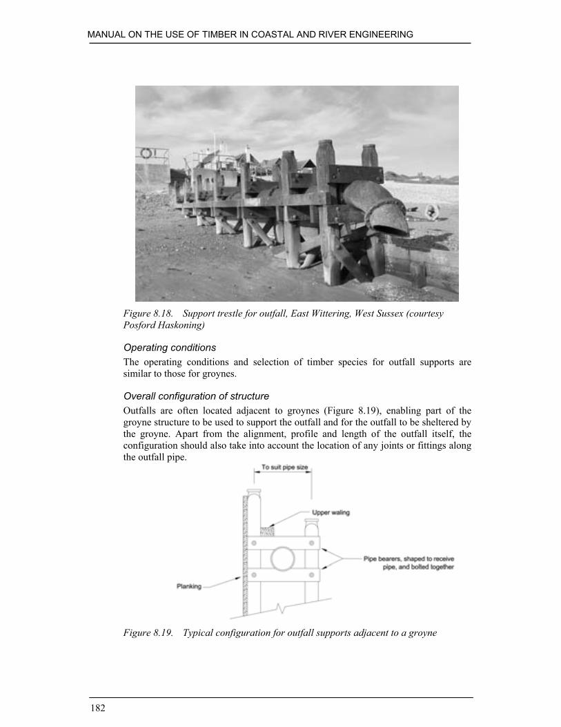
MANUAL ON THE USE OF TIMBER IN COASTAL AND RIVER ENGINEERING
182
Figure 8.18. Support trestle for outfall, East Wittering, West Sussex (courtesyPosford Haskoning)
Operating conditionsThe operating conditions and selection of timber species for outfall supports aresimilar to those for groynes.
Overall configuration of structureOutfalls are often located adjacent to groynes (Figure 8.19), enabling part of thegroyne structure to be used to support the outfall and for the outfall to be sheltered bythe groyne. Apart from the alignment, profile and length of the outfall itself, theconfiguration should also take into account the location of any joints or fittings alongthe outfall pipe.
Figure 8.19. Typical configuration for outfall supports adjacent to a groyne

STRUCTURE SPECIFIC GUIDANCE
183
Overall stability of structureOverall stability is usually achieved by means of pairs of structurally linked piles,with diagonal bracing if possible.
8.6. ACCESS STEPS AND BOAT SLIPWAYS
Timber is often used to construct access from the promenade or riverbank onto thebeach or into the water. Timber may present a slip hazard when wet, but is anattractive and durable material in many situations. See Figures 8.20 and 8.21.
Figure 8.20. Ekki boat ramp at Tankerton, Kent (courtesy Mackley Construction)
Choice of timber structureThe main choice can be between an open timber structure and a solid concretestructure, although open composite structures of steel and timber or steel and concreteare not uncommon. Open structures have the advantage of lower impact on thenatural movement of sediments and timber is often considered to be moreaesthetically pleasing as well as resulting in less environmental damage.

MANUAL ON THE USE OF TIMBER IN COASTAL AND RIVER ENGINEERING
184
Figure 8.21. Purpleheart access steps at Eastbourne, East Sussex (courtesyHR Wallingford)
Operating conditionsTimber structures can usually work in situations where, at least for much of the time,boating and pedestrian activities are feasible. Allowance for seasonal or periodicvariations in beach or bed levels should be made in designs; where conditions areparticularly harsh, it may be possible to provide steps which can be removed duringwinter to avoid them being damaged.
Timber speciesA significant consideration in selecting timber species for accesses is the likelihoodand impacts of splintering. For this reason some tropical hardwoods (such asgreenheart) should be avoided for treads, decks and handrails.
Overall configuration of structureThe main purpose of a slipway or a set of pedestrian steps is to facilitate access acrossa difficult terrain. This might include a significant change in level, an irregularsurface such as a rock revetment or an unstable surface such as a shingle beach. Indesigning such structures it is necessary to identify what constitutes a difficult terrainand how it might change under natural conditions.

STRUCTURE SPECIFIC GUIDANCE
185
Opportunities are often taken to incorporate accesses adjacent to other structures,notably groynes on beaches (Figure 8.22). This can afford the access a degree ofshelter and reduce abrasion as well as economising on the volume of timber required.
Figure 8.22. Dinghy (only) launching ramp at Shoreham Harbour built adjacent toa groyne
8.7. MOORING DOLPHINS, FENDER PILES AND RUBBING PIECES
Fender pilesThese are usually deflection structures to prevent direct collision of ships withreinforced concrete or steel structures. Fender piles may be constructed from one orseveral piles, driven into the bed a short distance in front of the structure to beprotected. The head of the pile is connected to the structure and a rubber buffer orspring is fixed between both. Another way of obtaining this spring effect is to drivesingle piles slightly tilted away from the structure and then pull the head towards thestructure and anchor it.
Timber rubbing piecesA range of timber species have been used successfully as rubbing pieces along jetties,piers, mooring dolphins and quay walls (Figure 8.23). The main requirements forrubbing pieces are the resistance to abrasion and splitting on impact. Rubbing pieces

MANUAL ON THE USE OF TIMBER IN COASTAL AND RIVER ENGINEERING
186
may easily be built-up of several timber sections, as the sections will mainly beloaded perpendicular to the joints. Elm, Douglas fir, pitch pine, oak, jarrah, opepe,ekki, okan are often-used species, frequently with a more durable timber mounted ona less durable species, this approach provides an economic solution whilstmaintaining a sufficient thickness to prevent impact damage in the main structure.
Navigation structures, to guide vessels and avoid damage arising from impactbetween vessels and waterside structures, are constructed frequently from timber.
Figure 8.23. Timber fenders at Axmouth Harbour (courtesy Posford Haskoning)
DolphinsThese are a cluster of piles tied together with horizontal and diagonal struts andbracings. They are used for moorings, as part of a lead-in jetty or to deflect shippingfrom navigation hazards such as bridge piers (Figure 8.24).

STRUCTURE SPECIFIC GUIDANCE
187
Figure 8.24. Timber piled lead-in structure to protect bridge pier at Reedham,Norfolk (courtesy Clive Orbell-Durrant)
Operating conditionsMooring piles and dolphins are vulnerable to accidental overloading. Care needs to betaken in selecting an appropriate operational load. Also, if possible, an appropriatefailure mechanism should be designed into the structure.
Members and connectionsTimber dowels, as opposed to steel fixings, can be an appropriate way of securingfenders and rubbing strakes to the parent timber structure. Dowels are more likely toexpand, contract and deflect in harmony with the connecting timbers, resulting in ajoint that remains tighter for a longer period of time. Also, any direct contact betweenthe vessel and a timber dowel is less likely to cause a problem than a steel fixing.
Finishes and fittingsThe actual navigational top mark, lantern, etc. is often a fitting to the main timberstructure. The arrangement and detailing of such fittings should facilitate inspection,maintenance and replacement.

MANUAL ON THE USE OF TIMBER IN COASTAL AND RIVER ENGINEERING
188
8.8. LOCK GATES, SLUICES AND FLAP GATES
8.8.1. Lock gates
Timber lock gates have traditionally been used on inland waterways (Figure 8.25) andstill are used widespread. British Waterways have 1591 locks across their system, ofwhich the majority are fitted with timber gates. The structure of timber lock gates isbased on centuries of experience and therefore is difficult to improve.Large lock gates may be constructed of steel, but often timber is used for the head andheel posts as it can be more easily fashioned on site to provide a water tight seal.
Figure 8.25. Timber lock gates on an upper reach of the River Thames (courtesyHR Wallingford)
Choice of timber structureTimber has several advantages over other materials: it has a high strength/weightratio, ability to withstand shock loads and ease of on-site repair. The majority of thelocks on inland waterways in the UK are hand-operated. On these gates, balancebeams are required for opening and closing the gate. Traditionally, these are large oaksections, e.g. 8.0 m long, but joining sections is possible. In some cases themechanical control is fixed to the balance beam and can be disconnected for manualoperation. The timber sizes required for the posts and planking are based on rathermore experience than calculation, as loads on the gates are difficult to predict.Accidental loading may well exceed a hundred times the hydrostatic load on a gate.

STRUCTURE SPECIFIC GUIDANCE
189
Operating conditionsThe life expectancy of timber lock gates is highly dependent on the operatingconditions; particularly, the amount of traffic on the waterway and mechanicaldamage are influential factors. Generally, a lifetime of 30 years can be expected forhardwood lock gates. In some cases hard- and softwood are combined within onegate, constructing the frames of hardwood and the sheeters of softwood. The sheetersare replaced every 10 to 15 years and the frame may last for over 50 years. Whenreplacing softwood sheeters for hardwood sheeters the balance beam should be fittedwith weights to compensate for the decreased drift of the gate. Joints and fittingsaffect the lifetime of a gate, as decay of the timber is likely to take place in theseareas first, and progressive failure will occur.
Timber speciesEkki, greenheart, some hardwood frames and softwood planking.
Overall configuration of structure (Figure 8.26)The height of a gate is preferably larger than the width to avoid deformation.
Figure 8.26. Typical conventional timber lock gate
PostsHead/mitre posts usually have a larger width than thickness and are cut at an angle,from about 0.3 to 0.5 times their thickness, where the set of gates contact.
The width of the heel post may be larger than the thickness and is usually cuthalf round.

MANUAL ON THE USE OF TIMBER IN COASTAL AND RIVER ENGINEERING
190
MembersThe top and bottom members have larger section sizes than the ones in-between. Thetop member and members regularly above the water surface should be shaped toallow water to run off. The thickness of the intermediate members together with thesheeting is the thickness of posts. In some cases, a strut member will be placed in aline diagonal from the bottom of the heel post to the top corner of the mitre post toprevent the gate from distorting. For the same purpose a steel pull bar or strip can befitted in the opposite diagonal. A bar will go through all the members and can beadjusted/tightened using a swivel placed above water at the top end of the heel post.
SheetersSheeters can be oriented in several directions, the most common being in the verticalor diagonal direction. Placing the sheeters parallel to the strut member, if used, willsupport its function. A large sheeter width should be chosen in order to reduce thenumber of gaps.
Waling/fenderingTo protect the gates from mechanical damage, timber fendering is attached to thewaling.
Members and connectionsTraditionally, the connections of members and posts of a gate are well-fitted mortiseand tenon timber joints made by skilled carpenters. Steel plates bolted on either sideof the timber sections support the joints. As the traditional timber joints are labourintensive to fabricate other possibilities have been sought. An example of a newlydeveloped joint by British Waterways is presented in Figure 8.27. This steel jointrequires less cutting of the timber. As the first joint of this design has only been fittedone year prior to writing, little can be said about its long term performance.

STRUCTURE SPECIFIC GUIDANCE
191
Figure 8.27. New joint for timber lock gates developed by British Waterways (a)joint detail and (b) as implemented in a lock gate in the workshop (courtesy BritishWaterways)

MANUAL ON THE USE OF TIMBER IN COASTAL AND RIVER ENGINEERING
192
The connection between gate heel posts and hollow quoins is an importantdetail, as this is where the gate hinges. When shut the connection should fit watertight, preferably causing as little abrasion as possible.
Lock gates are often fitted with walkways (see Figure 8.25) to allow pedestriansto cross the lock. Nowadays, gates tend to be fitted with aluminium prefabricatedwalkways, although in some cases the more aesthetic and traditional timber walkwaysare constructed on the gate. It should be borne in mind that a heavy walkwaystructure would increase the downward force and impart an extra torque on the gate.In some cases the balance beam may have to be weighted.
8.8.2. Sluices and flap gates
Figure 8.28 shows the mitre flap gates at the head of Lymington estuary whichprevent saltwater flowing upstream into the Lymington river. These vertically-hingedtwin-leaf gates (Figure 8.29) open when the fluvial head exceeds the tide level toallow river water to discharge into the estuary, and close when the incoming tide levelrises above the river level. The gates are constrained from opening fully so that thewater pressure from the incoming tide will push them closed.
The timber frames are constructed of ekki and the diagonal planking of pitchpine. Stainless steel brackets are used to reinforce the joints between the mainstructural members and vertical stainless steel rods are used to tie the main framemembers at quarter-span points.
Hardwood timber lock gates are best left unpainted; this allows the moisture inthe section to escape. Softwood finishing components such as walkways are bestpainted or impregnated with preservative because of their low resistance to decay.
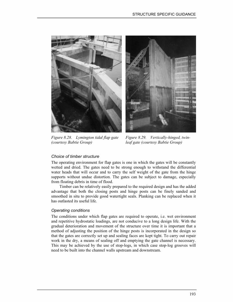
STRUCTURE SPECIFIC GUIDANCE
193
Figure 8.28. Lymington tidal flap gate(courtesy Babtie Group)
Figure 8.29. Vertically-hinged, twin-leaf gate (courtesy Babtie Group)
Choice of timber structureThe operating environment for flap gates is one in which the gates will be constantlywetted and dried. The gates need to be strong enough to withstand the differentialwater heads that will occur and to carry the self weight of the gate from the hingesupports without undue distortion. The gates can be subject to damage, especiallyfrom floating debris in time of flood.
Timber can be relatively easily prepared to the required design and has the addedadvantage that both the closing posts and hinge posts can be finely sanded andsmoothed in situ to provide good watertight seals. Planking can be replaced when ithas outlasted its useful life.
Operating conditionsThe conditions under which flap gates are required to operate, i.e. wet environmentand repetitive hydrostatic loadings, are not conducive to a long design life. With thegradual deterioration and movement of the structure over time it is important that amethod of adjusting the position of the hinge posts is incorporated in the design sothat the gates are correctly set up and sealing faces are kept tight. To carry out repairwork in the dry, a means of sealing off and emptying the gate channel is necessary.This may be achieved by the use of stop-logs, in which case stop-log grooves willneed to be built into the channel walls upstream and downstream.

MANUAL ON THE USE OF TIMBER IN COASTAL AND RIVER ENGINEERING
194
Timber speciesThe best choice of timber for the gate frame is a strong, durable hardwood such asgreenheart or ekki. A softwood, such as pitch pine, is suitable for the planking.
Overall configuration of structureThe height of the gate frame will generally exceed the width. The main framemembers are the hinge post, the closing post and the principal transoms. In theLymington gates the main members are the full depth of the gates, 340 mm. Thewidth of the hinge post is 340 mm, the closing post 280 mm tapering to 250 mm atthe bottom, and the principal transoms 300 mm. The gates have three intermediatetransoms which are 290 mm deep and 225 mm wide (upper two) and 300 mm wide(bottom). The planking is 50 mm deep, oversails the intermediate transoms, and isrebated into the main frame members. The diagonal planking runs from top outercorner to bottom hinge to help prevent sag of the gate.
The hinge post is supported on a cast iron pintle cast into the concrete floor slab.The pintle bears onto a socket recessed into the bottom of the hinge post. The top ofthe hinge post has a circular bronze band attached to it at top of wall height. Abracket rigidly fixed to the top of the wall has a strap attached to it which is wrappedaround the bronze band. The strap can be tensioned to pull the top of the post closerto the wall to ensure that the seal is kept as watertight as possible.
The gates are set-up slightly off the vertical so that their selfweight, when notinfluenced by water pressures, acts to keep the gates in the closed position.
Overall stability of structureThe gates rely upon the fixity provided by the pintle at the bottom of the hinge postand the strap adjustment at the top of the post for their stability. It is importanttherefore to ensure that the pintle and strap adjustment bracket are properly connectedto the channel structure and the forces imposed by the gates under load are taken intoconsideration in the design of the channel walls.
Members and connectionsThe main frame members are connected by mortise and tenon joints. The tenonconnections at the end of the transoms are highly stressed and the timber stressesshould be checked under maximum hydraulic loading conditions to ensure the tenonsizes are sufficient. All joints are reinforced by stainless steel plates on each face ofthe frame, which are bolted together through the structure.
Two vertical stainless steel rods are used on each leaf at quarter-span points totie together the top and bottom transoms.
Finishes and fittingsAll timbers have a machined finish. The hardwood timber frame is left in its naturalstate whilst the softwood planks have received a suitable preservative treatment.
Fittings are made from stainless steel except for some of the metalworkassociated with the hinge post, which is made from cast iron or bronze as describedabove.

STRUCTURE SPECIFIC GUIDANCE
195
Stop logsStop logs may be used to close off locks during maintenance or to prevent boats fromapproaching a weir. Often long softwood logs are used, as is for temporary purposes,H-section steel wrapped in heavy-duty polyethylene.
MaintenanceRegular maintenance inspections should be carried out to ensure that the gates aresealing adequately, that they are closing under the correct differential heads, they arenot obstructed by debris, and that they have not been damaged.
Adjustments can be made to the position of the top of the hinge post to improvethe sealing with the channel wall.
To remove debris from between the gates and the cill, and to fully inspect thegates in the dry, a winching arrangement is required to pull the gates into their ‘open’position. This can be achieved by connecting a wire rope from a winch located on thechannel wall to a metal ‘eye’ bolted to the top transom.
Full inspection and repair of the gates can only be carried out by temporarilydewatering the channel and it is essential therefore that a method of stanking-off thechannel is incorporated in the design. The normal method of achieving this is by theuse of stop-logs, and stop-log grooves should be built into the channel walls for thepurpose.
8.9. BED AND BANK PROTECTION AND STABILISATION
The structures discussed in this section use different material to those covered by therest of the Manual. Whereas elsewhere the material of choice will be heartwood, herewe are dealing with the use of sapwood (see Section 3.2 for explanation of thedifferences). In some cases, sapwood will comprise 100% of the material, in others itconstitutes such a high percentage that the useful life of the structure is governed byits presence. The structures covered by it are:
Fascines (including faggots and wipes) Submerged screensCribwork BrushwoodLive timber stabilisation HurdlesGabions Stakes (driven or planted)
Choice of timber structureThere are a number of reasons for opting for timber structures which use sapwood.
• It may be available as a waste product arising from bank, farm or forestmaintenance.
• It is an excellent habitat provider for a wide range of flora and fauna.• It is aesthetically pleasing.• Its production in quantity encourages traditional industries.• It may be the only workable engineering solution.• It may be required for heritage reasons.
MANUAL ON THE USE OF TIMBER IN COASTAL AND RIVER ENGINEERING
196
Operating conditionsAlmost invariably in Hazard class 5 (see Table 4.7).
Timber speciesWillows and osiers (salix spp.) and alders (alnus spp.) should be used where rootingis required; otherwise any of the traditional coppiced timbers may be selected.Brushwood can be taken from any deciduous species.
DurabilityEssentially these structures are not durable, however under certain conditions this canbe improved. This is achieved by:
• Controlled harvesting. This should be done to optimise sap retention. As sapprotects the growing wood from both insect and rot attack, its retention enhancesdurability (Box 8.3).
Box 8.3. Importance of cutting sapwood in due seasonBoth the durability and ease with which brushwood will strike can be greatlyenhanced by skilful harvesting. The ideal time to carry this out is when the sap isrising in the wood to be harvested. This varies with the species and the weather, butis generally mid to late winter, i.e. well before the birds’ nesting season. Someexamples of this are:
1. A farmer had a large willow tree blow down one winter. He needed to replace afence beside a wet ditch to keep cattle from falling in. He used the timber fromthe fallen willow to construct a post and rail fence. The posts took root, and hewas left with a line of nicely spaced willow trees that lasted long after the railshad rotted away.
2. The Forestry Commission put up a rack of birch brooms near some isolatedcottages so that the people living there had the means to hand to tackle wildfires before they became serious. After 18 months the broom heads were brittleand crumbling, and no use for their purpose. One of the cottagers cut somemore birch twigs when their sap was rising, and re-headed the brooms. Thenew heads came into leaf (albeit briefly) for the next 6 springs, and they stayedsupple for about 10 years altogether.
• Placing them in an anaerobic or low oxygen environment (Box 8.4).
Box 8.4. Durability in anoxic conditionsThe Romans built a causeway across a bog in Yorkshire on fascines to carry a road.This stayed in use until the 1950s, when it started to show signs of distress due to theweight of modern traffic – well above the original engineers’ brief! Afterunsatisfactory trials of a number of modern solutions, the local authority opened upsome osier beds to produce new fascines to replace and reinforce the originalconstruction.

STRUCTURE SPECIFIC GUIDANCE
197
Overall configuration and use of structures1. Fascines, faggots and wipes. The word fascine is derived from the Latin faces,
the bundle of rods surrounding the axe carried by the Lictors who precededRoman magistrates and symbolised their powers of punishment; Romanengineers developed the idea as an engineering tool. The basic form of all thesestructures is the tied bundle. Modern fascines range in diameter from a fewcentimetres (willow wipes as stiffening and stone retainers to geotextiles insea/river bed stabilisation) to several metres (‘instant’ crossings to anti-tankditches). Bundles can be tied side to side to form mattresses. As an engineeringtool they are underused, partly because many of the coppices and osier bedswhich produce the wood have fallen into disuse, so long lead times are needed torevive them before a major scheme can start. This does not conform well withcurrent funding practices. They are also labour intensive to produce, whichmakes them expensive by comparison with, say, geotextiles in manyapplications. On the plus side, fascines are nearly carbon neutral, not subject toUV attack, robust, provide flotation and have a good weight to strength ratio.
2. Cribwork. This is the baby brother of a grillage. Criss-crossed poles are filledwith stone to provide repairs to beds or banks. Brushwood should be included ifthe stone size is smaller than the poles to prevent them from washing out. Onthe riverbed the poles will need securing or weighting to keep them fromfloating. These are particularly useful for repairs to large washouts. Long termstabilisation is achieved by either sedimentation and/or plant roots binding thestone.
3. Live stabilisation. This is achieved by planting riverbank tree species to provideroot stabilisation to banks. To provide initial repairs, suitable species (willow,alder) are woven hurdle fashion around stakes planted into the bed; these thenroot and grow to form trees. The best results are achieved when using wood cutwith rising sap (Figure 8.30).
Figure 8.30. Construction of a fascine mattress (courtesy Henk Jan Verhagen)

MANUAL ON THE USE OF TIMBER IN COASTAL AND RIVER ENGINEERING
198
4. Gabions. The most traditional form of gabion is formed by planting uprightsclose spaced into the ground, then weaving thin wood between them to form aseries of adjacent cells which are then filled with earth or stone; horizontal layersare often incorporated to give lateral stability. They were used to provide astable core to sea and riverbanks from Roman times through to the nineteenthcentury. Military engineers also used them to provide protection againstbombardment, usually in circular form. They are very labour intensive, and havebeen almost entirely replaced by wire mesh boxes in modern applications, butthey may be a heritage requirement when ancient banks need repair.
5. Submerged screens. These are semi-permeable structures designed to deflectcurrents and encourage sedimentation. Typically, they consist of two rows ofstakes planted or driven into the riverbed in-filled with faggots (small gabions)or brushwood. As it is usually undesirable to have them replaced by a line oftrees, species such as willow and alder should be avoided for the stakes, asshould wood cut with rising sap (see Box 8.3).
Figure 8.31. Accreting faggot, Holwerd, The Netherlands (courtesyHR Wallingford)
6. Brushwood. Apart from its use in conjunction with other structures, brushwoodcan be useful in its own right. Bundles ballasted and placed in riverbed buttsupstream will form a snag and lead to the development of sand or mud bars.This application can also be used to perform minor bed repairs. Fixed to a fencein a stream they can be used to encourage sedimentation near banks to providelong term stability, and used with their butts driven into the bed to effect minorbank repairs.

STRUCTURE SPECIFIC GUIDANCE
199
7. Hurdles. Coppiced wood can be woven into panels known as hurdles. Thesecan be fixed at any angle and act in a similar way to brushwood, but are morerobust and can in addition form an effective ‘rustic’ fencing. They are normallyfixed between posts and, assembled off site, can be quickly put up in anemergency and are easily handled where access is restricted. They can also bereused. Laid horizontally they form a traditional means of reinforcing earthembankments.
8. Stakes. Stakes, or round posts, are the usual method of providing strength andfixity to items 4-7 above. As they are largely sapwood, their durability dependson the same factors, and their useful life tends to be of the same order. They canalso be used on their own, driven into the river bed to form lightweightmoorings, as a screen to stop boats from approaching sections of bank, assupports for walkways, causeways and light jetties, and contiguously to form atemporary bank support or protection. In the latter case they are known asmodular piles (Figure 8.32).
Figure 8.32. Modular pile bank protection (after Environment Agency, 1999)
MaintenanceBy their very nature, these are very high maintenance structures. Growing structurescan be controlled by grazing, browsing or pollarding, but otherwise the owner isfaced with frequent inspection to remove debris which could cause immediate failure,especially in the case of the lighter structures, and may be faced with a totalreplacement situation as often as every two years if the bed or bank fails to stabilise.Careful and timely harvesting of the wood incorporated into the structures can reducethis commitment dramatically but, except in the case of structures in anaerobicconditions, maintenance will be much higher than it would be for tropical hardwoodsin the same hazard conditions.
LiteratureEnvironment Agency (1999). Waterway bank protection: a guide to erosion
assessment and management. Environment Agency, Bristol, UK.Graham, J.S. (1983). Design of pressure-treated wood bulkheads. Proc. Coastal
Structures ’83, pp 286-294, American Society of Civil Engineers.
MANUAL ON THE USE OF TIMBER IN COASTAL AND RIVER ENGINEERING
200
8.10. EARTH RETAINING STRUCTURES AND CLADDING
This section includes:
• Toe protection • River walls• Cladding • Composite cladding/walls
These form a continuum of cantilevered diaphragm structures, starting with simplecantilevered plank piles, and culminating in timber diaphragm held in position withanchored steel/concrete piles and walings. Cladding is normally trying to imitate afully timber structure in appearance, and may contribute to the utility of the structureas well.
Choice of timberThese structures tend to be used where the consequences of failure would not be tooserious, for instance:
• where there are no buildings or infrastructure behind the defence• where the retained height is relatively modest• where there is unlikely to be a high ground loading imposed behind the structure• it is a cheap alternative where a wall needs to be built forwards a short distance• to camouflage structures made of other materials• to mediate between other materials and river users, e.g. timber facine to an ‘H’
pile can both act as a fender and protect the pile protection system.
Operating conditionsAlthough not without exception, these structures tend to be used in less aggressiveconditions. They are more robust than those described in Section 8.9, but morevulnerable to failure than, say, a solid concrete or steel sheet-piled wall. Timber walldefences can be used in conjunction with soft defences to take the first impact ofwaves and currents and prevent undermining or uprooting of reed beds (rands) orgrass slopes, especially in time of flood, or where there is a lot of seasonal boattraffic. Where ship wash is a serious problem, timber protection is unlikely to beadequate. Hazard class is usually Class 5.
Timber speciesThe selection of the most appropriate timber species relates to the following issues:
• strength of timbers, especially piles during driving• stability of timbers with regards to splitting and distortion• durability of members against decomposition, abrasion and marine borers.
Tropical hardwoods perform best in respect of the above criteria, but other speciesand/or treated timber should be considered, particularly where durability is not aprime consideration, the risks incumbent on failure are low or where they look out ofplace.

STRUCTURE SPECIFIC GUIDANCE
201
Overall configuration of structureThe posts and piles act in cantilever. A diaphragm is formed either with boardingfixed between the uprights, or driven in the form of plank piles (Figures 8.33 and8.34). Where appropriate a waling can add extra support, and may also double-up asa rubbing strip or fender. The choice between the various options will depend in thestrength of the hydraulic attack, the retained height and the use to which the particularlength of riverbank is put. Where the main concern is undermining, a breastwork canprovide toe protection. Toe erosion caused by wave or wake reflection can be aproblem.
Figure 8.33. Plank and post toe boarding (after Environment Agency, 1999)
Figure 8.34. Anchored timber piling (after Environment Agency, 1999)

MANUAL ON THE USE OF TIMBER IN COASTAL AND RIVER ENGINEERING
202
Overall stability of the structureCantilever piles need to be driven to three to five times the retained height. Wheresubstantial heights need to be supported, ground anchors or anchor piles or blockswith ties and walings may be required to provide sufficient support, especially in badground; additional support can be gained from buried planks (Figure 8.35). Anchoredpiles are usually shorter than full cantilever ones, as they normally need to be drivento only twice the retained height. All-timber construction is unlikely to be applicablewhere more than 3.5m of vertical support is required. When no anchors are used theground near the wall will settle in order to achieve passive soil resistance below.When anchors are used these should be placed outside the potential failure circle.The use of a raking structure can improve the efficiency of a design.
Figure 8.35. Typical section of river wall
Members and connectionsThese should be standard sections and lengths for ease of maintenance, generally toBS 5268. Fixings should be minimised, simple and designed to take account of anypredicted impact loads and to last the anticipated life of the structure. Claddingfixings should be able to last the life of the underlying structure.
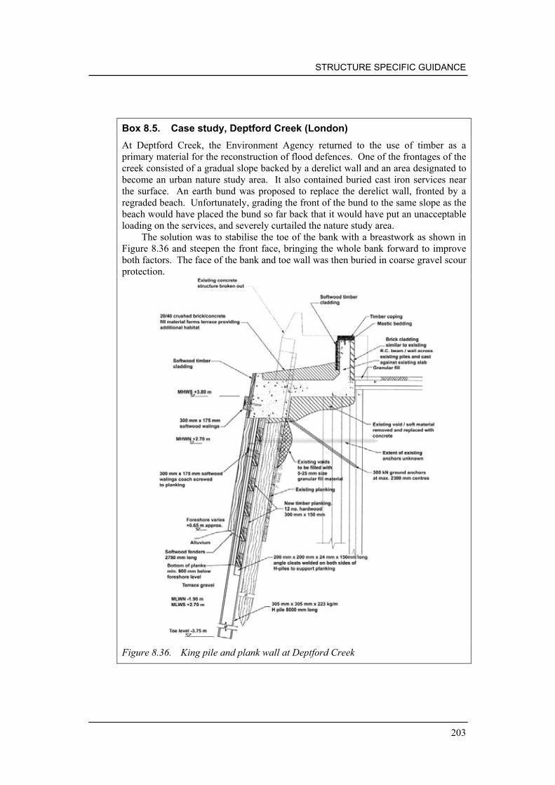
STRUCTURE SPECIFIC GUIDANCE
203
Box 8.5. Case study, Deptford Creek (London)At Deptford Creek, the Environment Agency returned to the use of timber as aprimary material for the reconstruction of flood defences. One of the frontages of thecreek consisted of a gradual slope backed by a derelict wall and an area designated tobecome an urban nature study area. It also contained buried cast iron services nearthe surface. An earth bund was proposed to replace the derelict wall, fronted by aregraded beach. Unfortunately, grading the front of the bund to the same slope as thebeach would have placed the bund so far back that it would have put an unacceptableloading on the services, and severely curtailed the nature study area.
The solution was to stabilise the toe of the bank with a breastwork as shown inFigure 8.36 and steepen the front face, bringing the whole bank forward to improveboth factors. The face of the bank and toe wall was then buried in coarse gravel scourprotection.
Figure 8.36. King pile and plank wall at Deptford Creek
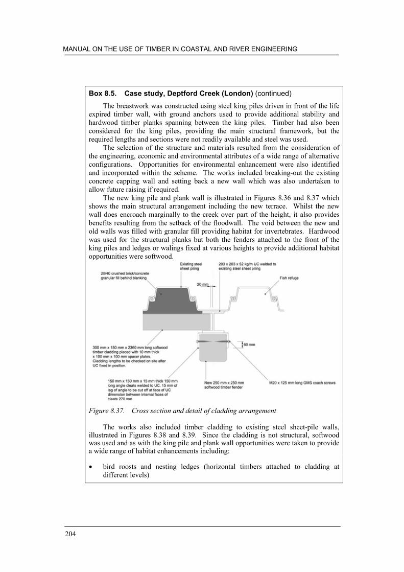
MANUAL ON THE USE OF TIMBER IN COASTAL AND RIVER ENGINEERING
204
Box 8.5. Case study, Deptford Creek (London) (continued)
The breastwork was constructed using steel king piles driven in front of the lifeexpired timber wall, with ground anchors used to provide additional stability andhardwood timber planks spanning between the king piles. Timber had also beenconsidered for the king piles, providing the main structural framework, but therequired lengths and sections were not readily available and steel was used.
The selection of the structure and materials resulted from the consideration ofthe engineering, economic and environmental attributes of a wide range of alternativeconfigurations. Opportunities for environmental enhancement were also identifiedand incorporated within the scheme. The works included breaking-out the existingconcrete capping wall and setting back a new wall which was also undertaken toallow future raising if required.
The new king pile and plank wall is illustrated in Figures 8.36 and 8.37 whichshows the main structural arrangement including the new terrace. Whilst the newwall does encroach marginally to the creek over part of the height, it also providesbenefits resulting from the setback of the floodwall. The void between the new andold walls was filled with granular fill providing habitat for invertebrates. Hardwoodwas used for the structural planks but both the fenders attached to the front of theking piles and ledges or walings fixed at various heights to provide additional habitatopportunities were softwood.
Figure 8.37. Cross section and detail of cladding arrangement
The works also included timber cladding to existing steel sheet-pile walls,illustrated in Figures 8.38 and 8.39. Since the cladding is not structural, softwoodwas used and as with the king pile and plank wall opportunities were taken to providea wide range of habitat enhancements including:
bird roosts and nesting ledges (horizontal timbers attached to cladding atdifferent levels)

STRUCTURE SPECIFIC GUIDANCE
205
Box 8.5. Case study, Deptford Creek (London) (continued)
opportunities for marginal vegetation (horizontal timbers attached to cladding atupper levels)fish refuges and spawning areas (openings in the cladding just above bed level toprovide sheltered areas out of the main flow)invertebrate habitats (access to granular fill behind the cladding betweencladding planks achieved by using spacer plates)
Figure 8.38. Deptford Creek frontage before (left) and after (right) (courtesy BabtieGroup)
Figure 8.39. Example of timber cladding from Deptford Creek
Finishes and fixingsThe larger structures require bolts and coach screws; for smaller ones, timber spikes,screws or nails may be adequate. All should be either galvanised or stainless steel.

MANUAL ON THE USE OF TIMBER IN COASTAL AND RIVER ENGINEERING
206
MaintenanceAll timber structures need regular maintenance. This can be minimised by using the‘little but often’ principle, whereby frequent inspection and reactive maintenance willidentify and rectify defects before they get out of hand. Points requiring particularattention are physical damage, vegetation control, washouts behind the structure,loose fixings and decay of timber near the waterline. The cost penalty for poormaintenance is premature and expensive refurbishment. Cladding maintenance canbe less onerous, as it can often be left until it becomes unsightly or a public hazard.
8.11. HABITAT PROVISION
One of the arguments for the use of timber is, that, as a natural material, it makes abetter habitat provider than materials such as steel or concrete. Of course this canalso be a drawback, as some of the beneficiaries, such as rot fungi, gribble, wood- andshipworm also accelerate degradation. Another beneficiary, which has a lowpopularity rating, is the brown rat (Rattus norvegicus). However, timber is easilyadapted to meet site specific habitat requirements, such as:
• fish refuges• bird perching, roosting and nesting sites• plant pockets• silt traps for invertebrates• spawning shallows• fry shelters• tunnels for crayfish and water rats• holts for otters• and in decay can play host to a wide range of insect larvae, much to the benefit
of their predators. See Box 8.5 for an example.

207
9. Monitoring and assessment oftimber structures
The monitoring and assessment of timber structures is of critical importance to theireffectiveness and durability. It is essential that any problem or deterioration isaddressed quickly before it becomes significantly worse.
9.1. THE DEGRADATION PROCESS
Over the course of time and through the influence of the external environment, timberstructures, like all other structures, experience a loss in performance, which isreferred to under the umbrella title of degradation.
Degradation is both inevitable and undesirable. At best, degradation is limited tothe surface layers of the timber structure. However, given the right conditions,degradation will eventually affect the whole structure, particularly in terms ofmechanical performance, strength and durability. The rate of degradation is usuallyspecific to the particular timber species and the environmental conditions of service.
The process of degradation can be subdivided into biological, chemical,photochemical, thermal, fire and mechanical degradation which are described in thefollowing sections.
9.1.1. Biological attack
Fungal decayTimber, provided it remains dry, i.e. below the decay threshold which is nominally20% moisture content, will not suffer from fungal decay. However, timber in themarine and river environment will, in most cases, remain permanently wet. Wherethose timber elements are out of contact with water or the ground, they will probablybe exposed to conditions that will result in them being vulnerable to intermittentattack (Figure 9.1).

MANUAL ON THE USE OF TIMBER IN COASTAL AND RIVER ENGINEERING
208
Figure 9.1. Advanced fungal decay in primary and secondary beams (courtesy JohnWilliams)
Fungal decay is both complex and variable and for it to occur, four conditionsmust be present: these are food, adequate moisture, suitable temperature and oxygen.In most circumstances, moisture is the limiting factor that restricts fungal activity.However, low levels of oxygen, limited nutrients and low temperatures also inhibitfungal activity. The timber itself or the cell contents provide the necessary nutrients.Oxygen is always available under service conditions except when the timber is totallywaterlogged. Practically all fungal activity ceases at or below freezing point and isvery slow just above it. Optimum conditions generally occur at around 20°C to 30°Cand at 30% to 50% moisture content.
The fungal decay process may be loosely summarised as follows:
• Moisture content exceeds decay threshold.• Bacterial, mould and sapstain attack. Mould and sapstain fungi are lower fungal
organisms that are best described as ‘scavengers’; they feed upon readilyavailable cell contents but do not cause ‘decay’ of the timber structure. Theirpresence, however, indicates that conditions favourable for fungal decay exist.
• Soft rot attack occurs in ground contact and in marine and river environments,and tends to favour conditions where the timber is very wet. Soft rots are also‘lower’ organisms.
• Dry rot attack is the most important destructive fungus found in buildings.However, with reference to timber structures in the marine and riverenvironment, dry rot is extremely rare.

MONITORING AND ASSESSMENT OF TIMBER STRUCTURES
209
• Wet rots are by far the most important group of fungi to consider in terms oftimber structures serving in the marine and river environment. Wet rot attack canbe minimised/prevented by appropriate detailing as discussed in Section 7.3.
Insect attackIn general, timber structures serving in the marine and fresh water environment arenot vulnerable to insect attack in the UK. However, there are exceptions to thisstatement and it should be qualified by the fact that sapwood regions that may exist insome timber elements will be attacked by wood-boring beetles. Ideally, untreatedsapwood should not be present on these types of timber structure and where sapwoodbands do exist, they will deteriorate rapidly. This may have consequences if fixingshave been located within sapwood areas.
Where insect attack is noted over the timber structure, i.e. it is not limited tosapwood, it will usually be coincident with fungal decay. Such insect attack iscommonly attributed to wharf-borer beetles and wood-boring weevil. Therefore, thepresence of such organisms serves as a warning that more insidious organisms are atwork degrading the structure.
Marine borersAll timber species are susceptible to attack by marine borers. The factors, which exertmost control over the rate of attack, are density, silica content and extractives.Marine borers may also be restricted by environmental conditions such astemperature and salinity.
9.1.2. Mechanical degradation
Timber serving in the marine and fresh water environment will suffer mechanicaldegradation. By far the most common cause of mechanical deterioration of timberoccurs when it is stressed under load for prolonged periods of time – this is known ascreep. Creep may be defined as a loss in strength with time under load. For example,for a timber element to sustain a load for 100 years, then the load must not exceed50% of the load the timber would fail at in the short term. In all structuralapplications, a load endurance factor should be incorporated in the design and isusually applied as one of several contributing parts to an overall safety factor.
In the marine and fresh water environment, tidal action, beach abrasion andimpact can all affect the integrity of timber structures. With reference to impactdamage, this can result in compression failure of the timber fibres. Abrasion can be amajor factor in determining the life of a timber structure and may be most apparent inareas where there is a small tidal range as the erosion will be concentrated on arelatively small part of the structure.
9.1.3. Chemical degradation
The most important characteristics relating to chemical resistance are impermeabilityand density. Chemical attack is restricted to the surface of the timber and can be

MANUAL ON THE USE OF TIMBER IN COASTAL AND RIVER ENGINEERING
210
caused by acid or alkaline chemicals. Degraded wood surfaces have a ‘fluffy’appearance, i.e. defibrillation of the wood fibres, and are quickly eroded. The attackis superficial. In the marine environment, sea spray results in salt deposit forming onthe wood surface which can result in defibrillation of the fibres. One positive sideeffect of these salt deposits is that they act as a natural preservative and discouragemany species of fungi from degrading the timber.
9.1.4. Photochemical degradation
On exposure to ultra-violet light, the coloration of the heartwood of most species(such as teak, mahogany and iroko) will lighten although a few species such asDouglas fir will actually darken. Colour change is part of the photochemicaldegradation process. The effects of wind and rain also cause complex degradation atthe timber surface. Weathering results in the loss of surface integrity of the timberand affects its appearance. Generally, weathering does not the affect the long termperformance and strength of timber elements. There is one exception and that is thebreakdown of surface finishes, i.e. paint films, can result in premature failure ofjoinery products as water penetrates through the paint film and elevates the moisturecontent of the component to levels which can support fungal decay.
The rate of photochemical degradation and weathering results in slow erosion ofthe timber surface and can act as a precursor to fungal decay. With reference tomaritime and fresh water structures comprising dense, large sections of timber,weathering is insignificant.
9.1.5. Thermal degradation
Very low temperatures have no effect on the strength properties of timber. High valuesoftwoods originate from well within the Arctic Circle where for many months of theyear the tree is standing in permafrost. Thermal degradation only occurs in timbersthat are exposed to high levels of radiant heat where the surface can attain atemperature above 100oC. The surface of the timber will darken.
9.1.6. Degradation by fire
Timber is an organic material, and as such is combustible in the dry state (Figure 9.2).The thermal energy required to ignite and sustain the combustion of timber isconsiderable. Timber has the ability to form a char layer, which is a good insulatorthat retards combustion. The behaviour of timber in fire is predictable in relation tothe section size of the component and its density.
Fire degradation in marine structures may be viewed as uncommon and canoccur by accident or by vandalism. Where fire degradation has occurred, very often itis possible to predict the residual strength of the structure by considering the reducedsections of timbers which have been protected by the char layer.

MONITORING AND ASSESSMENT OF TIMBER STRUCTURES
211
Figure 9.2. Fire damage down to the water line of Southend Pier (courtesyEcotimber Ltd.) – see also Section 10.2
9.2. MONITORING AND ASSESSMENT
Timber structures should be monitored and surveyed as part of a regular maintenanceregime. The frequency and extent of the surveys will be dependent upon the level ofrisk the structure is exposed to, and also on previous survey results. For example, atimber structure situated in a location where there is a high incidence of marine borerwould have to be monitored at more frequent intervals than a comparable structurelocated where there is a low risk of marine borer.
Furthermore, a structure made of a moderately durable timber would, generally,have to be monitored more frequently than a structure made out of a very durabletimber.
There are a number of methods used by the surveyor to assess the condition of atimber structure and to enable the surveyor to estimate its potential life span. Theseinclude visual and other non-destructive (such as ultrasound examination) techniquesas well as intrusive techniques such as drilling or probing.
9.2.1. Inspection of timber structures
There are five factors which must be considered when inspecting timber structures:
MANUAL ON THE USE OF TIMBER IN COASTAL AND RIVER ENGINEERING
212
• the timber species used in the original construction and the species of anyreplacement components
• evidence of preservative treatments – this may be determined both quantitativelyand qualitatively
• identification of the presence and severity of mechanical and/or biologicaldegredation
• appraisal of the condition, size and location of the relevant timber components• condition of fixings and joints. Poor detailing of joints and selection of
inappropriate fixings can significantly shorten the life of the structure.
Having carried out a preliminary visual inspection of the structure, the fastest methodof surveying any timber structure is to use hammer soundings to determine theresonance. The timber components are struck at regular intervals consistent withforce applied in the hammer blow. This technique provides an indication of grossdeterioration. Large pockets of decay are coincident generally with areas that soundhollow when struck. Fissuring, mortising and notching of the timber can influencehammer soundings, so the surveyor should be aware of these features that mayinfluence the findings.
Decay detection drilling may be used to determine the condition of timbercomponents. However, when surveying timber structures that have been constructedfrom heavy, dense timbers such as ekki, greenheart and balau, this method isextremely time-consuming. This is a particular disadvantage when working withinshort time windows governed by the prevailing tides. Specialist drilling equipment isoften used. Such apparatus can produce a printout of the timber’s resistance to a sharpneedle-like probe applied to the face of the timber using a constant force. The printoutillustrates a profile of the timber components’ hardness. Significant changes inhardness, illustrated on the printout, may indicate the presence of fungal decay orsignificant marine borer attack. The surveyor must also be aware that fissures and thepresence of pith may also affect the printout.
A faster method of decay detection drilling is to use wood augers of typically6 mm diameter and an electric drill. Although this method does not produce a printoutof the areas surveyed there are obvious advantages with this method when time onsite is limited by tidal factors. This method also requires a high degree of surveyorcompetence and experience. It is important to carry out the drillings in a consistentmanner, i.e. apply constant force when drilling and ensuring the wood augers arereplaced frequently.
In conjunction with drilling, the surface of the timber should be probed with asharp screwdriver or bradawl. This will enable the surveyor to identify areas ofsurface softening, and possibly, severe deterioration. It is particularly appropriate inareas around joints and fixings should be carefully surveyed by this method withminimum damage to the structure.
Increment core samples may be taken from the timber structure using a Presslerborer. This technique enables the surveyor to assess the condition of the timber underlaboratory conditions. Microscopic analysis may reveal fungal activity. These coresamples may also provide sufficient material for species identification andpreservative analysis. It should be borne in mind that core samples represent a verysmall proportion of the timber structure. Taking core samples can prove to be a

MONITORING AND ASSESSMENT OF TIMBER STRUCTURES
213
valuable exercise where the condition of the inaccessible surfaces of decking boards,for example, need to be determined. Specialist timber-coring equipment should beprocured so that core samples may be extracted from dense tropical hardwoods.
To determine the residual strength and life span of any timber component it isimportant to know the original dimensions of the component, its current dimensionsand its condition. This is often possible in cases where the timber structure has beenexposed to attack by soft rot fungi and gribble, as the attack is superficial.Determining the rate of deterioration should enable the surveyor and engineers toestimate the remaining useful life expectancy by estimating the time it will take forthe structure to erode down to its minimum serviceable cross-section area.
However, it is important to recognise the type of deterioration affecting thestructure and to categorically define the full extent of fungal decay, if present. Insome cases, this can prove to be difficult as the early onset of decay by wet rot fungi,for example, may not always be detected by survey methods. Therefore regularinspections of the structure should be incorporated as part of any maintenance regime.As fungal decay develops, it usually does so at an ever increasing rate with the resultthat the subsequent loss in strength of the component also occurs at an everaccelerating rate. Where attack by shipworm has occurred, estimating the residualstrength and life span of affected components is notoriously difficult and wouldinvolve detailed, destructive assessment of a number of the timber components.
In general terms, the following points may be considered by the experiencedtimber surveyor.
• In all cases, where the timber element is below the riverbed or beach level, thetimber will remain relatively free from biological attack. The greatest hazard isat the intertidal zone for the marine environment and between the high and lowwater marks for river environments.
• In cases where the timber is uncovered, out of contact with water and out ofground contact, the Hazard class HC3 will apply. The timber may be at risk offungal decay intermittently and care should be exercised when surveying,especially around joints and horizontal shaded surfaces where moisture cancollect.
• Timber in ground contact is particularly vulnerable at the interface between thesoil and air. As the ground surrounding the timber element is excavated togreater depths, the likelihood of finding external fungal decay diminishes due tothe lack of oxygen. For example, the ground around timber posts is usuallyexcavated to a depth of 0.5 m and the pole surveyed for decay.
9.3. IDENTIFICATION OF TIMBER SPECIES
The importance of correctly identifying the timber species has already been stated.Although different species of timber may be assigned the same visual grade, they arenot assigned to the same strength class. For example HS grade iroko may be assigned

MANUAL ON THE USE OF TIMBER IN COASTAL AND RIVER ENGINEERING
214
to strength class D40 whereas HS grade greenheart may be assigned to strength classD70.
At first sight, the identification of timber appears to be a relativelystraightforward exercise. However, literally thousands of species exist and, veryoften, correct identification is an extremely difficult and complex task, best carriedout by an experienced anatomist or timber technologist. In some cases, it is notpossible to identify a specific species although it may be possible to narrow it downto a species group. Two examples of species groups are given below.
• Southern yellow pine is the commercial term for several closely related speciesincluding Pinus palustris (longleaf pine), Pinus elliotii, (slash pine) Pinusechninata (shortleaf pine) and Pinus Taeda (loblolly pine). It is not possible todifferentiate between these timbers using anatomical features of the timberalthough differentiation is possible on botanical features for example, needle andcone sizes.
• Meranti, seraya and lauan are the commercial names given to a large number ofspecies of the genus Shorea distributed throughout Southeast Asia. Generally,the name ‘meranti’ applies to timber from Malaya, Sarawark and Indonesia.Seraya applies to timber from Sabah, and Lauan for timber from the Philippines.The timbers may be further grouped by colour and density but it is often notpossible to distinguish individual species.
Most end users of timber handle a narrow range of species and are able to identify thetimber by briefly examining the gross features of the wood combined with anappreciation of the member’s mass. Typical gross features are:
• colour• mass• odour of freshly cut surfaces• texture and grain• conspicuous rays and vessels.
This approach is suitable where interest is confined to a limited species range.However, where identification requires a higher degree of assurance, samples mayneed to be examined using a hand lens or a microscope and computer aidedidentification keys. This will normally require one or more samples (typically, eachthe size of a matchbox) to be provided for a specialist to examine in detail. Whentaking such samples care must be exercised to ensure that they are representative ofthe structure as a whole rather than being selected from parts of the structure that arein the best or worst condition.

215
10. Maintenance, repair andenhancement of timber structures
Timber structures, typically, require a relatively high commitment of maintenanceand repair activities. It is important that this is budgeted for at the outset andconsidered within the design approach and selection of materials.
10.1. DESIGN PROCESS
In addition to ensuring that design details contribute to the durability of timberstructures, it is important that provision is made for necessary maintenance and repairworks. The design process should actively consider the likely works required over thewhole duration of the scheme lifetime and ensure that maintenance activities can beundertaken safely and efficiently. This may include steps such as using stainless steelbolts and coach screws which are far more durable than mild or galvanised steel and,consequently, much easier to undo after a few years exposure to the sea. Similarly,where different elements of a structure have different service lives (such as softwoodplanking on a hardwood frame, or the planks and piles of a groyne) considerationmust be given to the replacement of the less durable components. Where elements ina particular location suffer greatest degradation (such as the high waterline on lockgates), the design of other components (in this case the frame) may be altered tominimise the quantity of material replaced.
The design process should seek to attain:
the lowest whole life costs, provided that the required functionality is retainedthe least impact on the environment in maintaining and operating the asset,including the sourcing of the construction materials used in any repairsretained functionality whilst maintenance and repair of specific assets is carriedoutpredictable performance under the impact of an extreme event beyond the designstandardease of repair (readily accessible connections joints and minimum wastage whenreplacing elements)minimal negative impacts and the maximum benefits to society over the life ofthe asset.

MANUAL ON THE USE OF TIMBER IN COASTAL AND RIVER ENGINEERING
216
Careful detailing during the design and construction phase can significantly reducethe overall maintenance commitment for some timber structures.
10.2. MAINTENANCE ACTIVITIES
Maintenance of timber structures may be undertaken for a number of reasonsincluding:
replacement of damaged or degraded elements (see Figure 10.1)adjustments to the structure profile or configuration to increase effectiveness (forexample, adjusting the height of a timber groyne)to ensure public safetyavoidance of further damage (for example, loose planking on a groyne or lockgate vibrating excessively and causing damage to primary and/or secondarystructural elements).
Figure 10.1. New timber fixed onto old as part of refurbishment of fire damagedSouthend Pier (courtesy Southend Borough Council) – see also Section 9.1.6
Most maintenance regimes combine routine inspections with reactive repairs.This avoids excessive costs and possibly unnecessary work which could result fromstrictly programmed maintenance activities, but still ensures that defects can bespeedily identified and remedied. With experience it is often possible to predictwhere maintenance work will be needed and even sometimes to put proactivemeasures in place (see, for example, Box 10.1).

MAINTENANCE, REPAIR AND ENHANCEMENT OF TIMBER STRUCTURES
217
All timber structures will require the bolts and coach screws to be tightened fromtime to time in service. This is usually the result of shrinkage in service if the timberis above the intertidal zone. Other factors that can result in loosening of the fixingscan be local yield at points of high stress or reversal of loading as temporary supportsare removed.
Box 10.1. Use of plywood backing to groyne planks at BournemouthBournemouth has a field of 50 impermeable timber groynes, typically 75 m long at180 m spacing. The piles are 300 mm 300 mm, and the planks are 300 mm 100 mm, and predominantly greenheart. Six groynes were planked with ekki, onewith balau, and one with jarrah in the mid 1980s. The beach is a fine sand, with anappreciable shingle content.
Older groynes display slight gaps between their planks. Sand transport throughthe gaps is considerable, and abrasion increases the width. Shingle becomes jammedin the opening, preventing closure when the timber expands in the summer months.Sand transport increases when the gaps reach about 10 mm, and beach levels fallagainst the groyne.
A simple, cost-effective form of repair is the addition of ‘tingles’; marine ply cutto 2400 mm 100 mm 38 mm and nailed over the gaps with stainless steel ring-shank nails. Tingles have a useful life of two to five years but are cheap and easy toreplace.
New groynes also display gaps of 1 to 3 mm between brand new planks becauseof dissimilar widths or bows. Whole sheets of marine ply are fitted to the shelteredside of the planking, to seal the gaps and prevent the onset of erosion. The first panelswere fitted with ring shank nails, but a few panels came loose in storms, and boltswere used instead (see Figure 10.2). Later, coach screws were used to avoid drillingholes through the greenheart planks. The oldest panels have been in place for sevenyears, rendering the groynes completely impermeable. This delays the onset of inter-plank abrasion, and extends the life of the greenheart planks.
Gribble has been increasingly noted at Bournemouth in recent years, infestingthe edges of a minority of greenheart planks in the intertidal zone. Some planks wereseverely damaged in just seven years. A few panels have been removed forinspection, to ensure that they do not increase gribble attack on the sheltered side ofthe greenheart, or the ply itself.
Two types of plastic panels have been used, to eliminate the risk of gribbleattack.

MANUAL ON THE USE OF TIMBER IN COASTAL AND RIVER ENGINEERING
218
Figure 10.2. Use of plywood backing to groyne planks at Bournemouth (courtesyBournemouth Borough Council)
An example of the maintenance regime for timber groynes adopted by a localauthority on the south coast of England is provided in Box 10.2. It is notable thatfocused, relatively low cost maintenance activities can have a significant impact onthe longevity and durability of timber structures, yielding considerable economicbenefits. One example of such works is the use of rubbing pieces on the piles oftimber groynes to protect them from abrasion.
Box 10.2. Repairs and maintenance of timber groynes: Arun DistrictCouncilArun District Council recognises abrasion as the main problem on their groynes. Thetwo main areas of abrasion are on the piles, at beach level on the down-drift sidecaused by the wave run-up and back wash, and immediately above planking levelwhere shingle is moved over the groyne by the wave action.
Beach levels are allowed to settle for approximately two years followinginstallation of the groyne and then an assessment is made of the need and location for‘pile rubbing strips’. These are sacrificial lengths of old planks or offcuts of newplanking coach screwed or bolted to the pile in a suitable location to bear the brunt ofthe worst abrasion. These can then be replaced as necessary at a later date orrelocated to a new area on the pile to ensure there is no abrasion to the main pilestructure.
General maintenance of groynes is facilitated by biannual inspections, whichfeed into an annual maintenance contract with the works normally carried out by thein-house works section. The inspections are supplemented by ad-hoc inspections

MAINTENANCE, REPAIR AND ENHANCEMENT OF TIMBER STRUCTURES
219
Box 10.2. Repairs and maintenance of timber groynes: Arun DistrictCouncil (continued)
carried out during other works and by information from the public. We tell the localresidents that they are our eyes on the beach and they realise that early replacement ofa lost or broken plank is generally in their interests.
Generally, maintenance consists of replacement of missing or broken planks,fixing of additional planks as the beach profile is improved and the fixing of pilerubbing strips. Gradual raising of plank levels also spreads any abrasion over a widerarea of the pile hence reducing the overall impact.
There are approximately 300 timber groynes on the Arun District Councilfrontage and the coast protection maintenance budget is in the region of £70 000 perannum. This budget is provided to cover all maintenance costs, including timbersupply and execution of the works. Of that annual budget, approximately £40 000will be utilised on timber purchase and timber groyne repairs and maintenance.
10.3. END OF LIFETIME
At a certain point a timber structure will have to be replaced or dismantled andreconstructed, usually because it presents a significant safety hazard or maintenancebecomes increasingly uneconomic. The timing of this is usually determined by thecondition of the primary members, which are the most difficult and expensive toreplace.
Once a structure is deemed to have reached the end of its useful life it isimportant that a thorough assessment determines the most appropriate replacement,taking care to learn lessons from the performance and condition of the previousstructure. Depending on the structure in question it may be beneficial to construct thereplacement before dismantling the original, as this minimises disruption of thefunction provided. However, it could make direct reuse of substantial quantities oftimber difficult, as this will need to be stored until the next work is undertaken.
The life expired structure should be carefully dismantled rather than demolished,with any opportunities to recycle materials carefully explored and minimal damagecaused to the substrate. Waste timber can normally be recycled in some form or usedfor energy recovery, but great care must be taken with preservative-treated timbercomponents. It should be noted that preservative-treated timber is now classified ashazardous waste and therefore:
cannot be burntcarries a premium when disposed of to tip.
These factors need to be taken into account when carrying out whole life costingsagainst untreated hardwoods. There is some research into the possibility of recycling,but results will be too late for this publication.

MANUAL ON THE USE OF TIMBER IN COASTAL AND RIVER ENGINEERING
220
10.4. SELECTION OF TIMBER
The selection of appropriate materials for the repair and adaptation of timberstructures is largely determined by the original materials and anticipated residual lifeof the remaining structural components. It is often prudent to keep a stock ofappropriately dimensioned timbers to allow groyne or deck planks to be repaired withthe minimum of delay.

221
11. References
Baharuddin, H.G. and Simula, M. (1996). Timber Certification in Transition.International Tropical Timber Organisation, Kuala Lumpur.
Brookes, A. and Agate, E. (2000). Sand dunes: a practical handbook. British Trustfor Conservation Volunteershttp://handbooks.btcv.org.uk/handbooks/index/book/137
BS 144: 1997 Specification for coal tar creosote for wood preservation (AMD 9947).
BS 373: 1957 Methods of testing small clear specimens of timber.
BS 648: 1964 Schedule of weights of building materials (AMD 105) (AMD 344).
BS 1282: 1999 Wood preservatives – Guidance on choice, use and application.
BS 4072: 1999 Copper/chromium/arsenic preparations for wood preservatives.
BS 4169: 1988 Specification for manufacture of glued-laminated timber structuralmembers (Partially superseded by BS EN 392).
BS 4978: 1996 Visual strength grading of softwood (AMD 9434).
BS 5268-2: 2002 Structural use of timber. Code of practice for permissible stressdesign, materials and workmanship.
BS 5268-5: 1989 Structural use of timber. Code of practice for the preservativetreatment of structural timber.
BS 5450: 1999 Round and sawn timber – permitted deviations and preferred sizes.Hardwood sawn timber.
BS 5589: 1989 Preservation of timber.
BS 5666-1: 1987 Methods of analysis of wood preservatives and treated timber.Guide to sampling and preparation of wood preservatives and treated timber foranalysis.

MANUAL ON THE USE OF TIMBER IN COASTAL AND RIVER ENGINEERING
222
BS 5666-2: 1980 Methods of analysis of wood preservatives and treated timber.Qualitative analysis.
BS 5707: 1997 Specification for preparation of wood preservatives in organicsolvents.
BS 5756: 1997 Visual strength grading of hardwood.
BS 5930: 1999 Code of practice for site investigations.
BS 6349-1: 2000 Maritime structures. Code of practice for general criteria.
BS 6349-6: 1989 Code of practice for maritime structures. Design of inshoremoorings and floating structures.
BS 6399-1: 1996 Loading for buildings. Code of practice for dead and imposed loads(AMD 13669).
BS 6399-2: 1997 Loading for buildings. Code of practice for wind loads (AMD13392) (AMD Corrigendum 14009).
BS 6399-3: 1988 Loading for buildings. Code of practice for imposed roof loads(AMD 6033) (AMD 9187) (AMD 9452).
BS 7359: 1991 Nomenclature of commercial timbers including sources of supply.
BS 8004: 1986 Code of practice for foundations.
BS 8417: 2003 Preservation of timber – recommendations.
BS EN 275: 1992 Determination of the protective effectiveness against marineborers.
BS EN 301: 1992 Adhesives phenolic and aminoplastic for load-bearing timberstructures. Classification and performance requirements.
BS EN 335: 1992 Hazard classes of wood and wood-based products againstbiological attack.
BS EN 338: 1995 Structural timber. Strength classes.
BS EN 350: 1994 Durability of wood and wood-based products. Natural durability ofsolid wood. Part 1. Guide to the principle of testing and classification of thenatural durability of wood. Part 2. Guide to the natural durability and treatabilityof selected wood species of importance in Europe.
BS EN 351-1: 1996 Durability of wood and wood-based products – Preservative-treated solid wood. Classification of preservative penetration and retention.
REFERENCES
223
BS EN 386: 2001 Glued laminated timber – Performance requirements and minimumproduction requirements.
BS EN 408: 1995 Timber structures. Structural timber and glued laminated timber.Determination of some physical and mechanical properties.
BS EN 460: 1994 Durability of wood and wood-based products - Natural durabilityof solid wood – Guide to the durability requirements for wood to be used inhazard classes.
BS EN 519: 1995 Structural timber. Grading requirements for machine strengthgraded timber and grading machines.
BS EN 599: 1997 Durability of wood and wood-based products – Performance ofpreventive wood preservatives as determined by biological tests.
BS EN 844-1: 1995 Round and sawn timber. Terminology. General terms.
BS EN 1313: Part 1 (softwoods):1997 Round and sawn timber – permitted deviationsand preferred sizes.
BS EN 1313: Part 2 (hardwoods): 1999 Round and sawn timber – Permitteddeviations and preferred sizes.
BS IS 15686 Service life planning of buildings and constructed assets.
BS EN ISO 1461: 1999 Hot dip galvanised coatings on fabricated iron and steelarticles – specification and test methods.
BS EN ISO 14001 Environmental Management Systems. Specification with guidancefor use.
BWPDA (1999). The British Wood Preserving and Damp-proofing Associationmanual. The British Wood Preserving and Damp-proofing Association.
Certified Forest Products Council (2002). Available from www.certifiedwood.org
CDM (1994). The construction (Design and Management) Regulations StatutoryInstrument 1994 No. 3140. London: the Stationery Office.
CIRIA (1996). Beach management manual. Simm, J.D., Brampton, A.H., Beech,N.W. and Brooke, J.S. (eds.). Construction Industry Research and DevelopmentAssociation, Report 153.
Council Directive 76/769/EEC of 27 July 1976 on the approximation of the laws,regulations and administrative provisions of the Member States relating torestrictions on the marketing and use of certain dangerous substances andpreparations.

MANUAL ON THE USE OF TIMBER IN COASTAL AND RIVER ENGINEERING
224
CP 3: Chapter V-2: 1972 Code of basic data for the design of buildings. Loading.Wind loads (AMD 4952) (AMD 5152) (AMD 5343) (AMD 6028) (AMD 7908)(No longer current but cited in building regulations).
DD ENV 1995-1-1: 1994 Eurocode 5. Design of timber structures. General rulesand rules for buildings.
Defra (2001). Government timber buying power to help combat illegal logging.Department for Environment, Fisheries and Rural Affairs. Available fromhttp://www.defra.gov.uk/news/2001/011123b.htm
Dutch Ministry for Nature Management (1997). Timber certification and sustainableforestry. Department of Nature Management, Dutch Ministry of Agriculture,Nature Management and Fisheries, Feb 1997.
DWW (1994). Wijzer 65, Hout in de waterbouw. [Timber in the waterways – inDutch]. [Rijkswaterstaat] Dienst Weg- en Waterbouwkunde, Delft, TheNetherlands.
ECOPRO (1996). Environmentally friendly coastal protection, Code of Practice.Eolas Offshore & Coastal Engineering Unit, Dublin, Ireland.
Environment Agency (1999). Waterway bank protection: a guide to erosionassessment and management. Environment Agency, Bristol, UK.
Environment Agency (2003). UK Climate Impacts Programme 2002 Climate ChangeScenarios: implementation for flood and coastal defence: guidance for users.Environment Agency R&D Technical Report W5B-029/TR. Available fromhttp://www.environment-agency.gov.uk/commondata/105385/w5b_029_tr.pdf
Environmental Audit Committee (2002). Buying time for forests: Timber trade andpublic procurement. The Stationery Office. Available fromhttp://www.parliament.the-stationery-office.co.uk/pa/cm200102/cmselect/cmenvaud/792/792.pdf
Environmental Impact Assessment (EIA) Regulations (1999). The town and countryplanning (Environmental Impact Assessment (England and Wales) Regulations.Statutory instrument 1999 No. 293. Available fromhttp://www.hmso.gov.uk/si/si1999/19990293.htm
Environmental Resources Management (ERM) (2002). Procurement of timberproducts from ‘legal & sustainable sources’ by Government & its executiveagencies : Scoping Study Report. Available fromwww.forestforum.org.uk/docs/scopingstudyreport6-8-02.pdf
EU FLEGT (2002). The EU & Forest Law Enforcement, Governance and Trade.Available from http://europa.eu.int/comm/external_relations/flegt/intro/

REFERENCES
225
European Forestry Institute (EFI) (2000). Criteria and indicators for sustainablemanagement at the forest management unit level. Available fromhttp://efi.fi/publications/Proceedings/38.html
FAO (2001). Global Forest Resources Assessment 2000. United Nations Food andAgriculture Organization, Rome. Available fromhttp://www.fao.org/forestry/fo/fra/main/index.jsp
Fleming, C.A. (1990). Guide on the uses of groynes in coastal engineering.Construction Industry Research and Information Association, Report 119,London.
G8 (1998). G8 Action Programme on Forests. Available fromhttp://birmingham.g8summit.gov.uk/forfin/forests.shtml
Gardner, J.D., Townend, I.H. and Fleming, C.A. (1986). The design of a slottedvertical screen breakwater. Proc. 20th Intrnl Conf. on Coastal Engineering,American Society of Civil Engineers.
Graham, J.S. (1983). Design of pressure-treated wood bulkheads. Proc. CoastalStructures ’83, pp. 286-94, American Society of Civil Engineers.
Guyana Forestry Commission (2002). Guyana timber grading rules for hardwoods.3rd Ed. produced with support from the ACP-EU Trade development project.Pavnik Press.
Health and Safety Executive (2003). Toxic woods: Wood working sheet 30.
HMSO (1997). Handbook of hardwoods. Her Majesty’s Stationary Office, London.
House of Commons (2002). Buying Time for Forests: Timber Trade and PublicProcurement. Environmental Audit Committee. House of Commons. Availablefrom http://www.parliament.the-stationery-office.co.uk/pa/cm200102/cmselect/cmenvaud/792/79202.htm
IWEM (1987). River engineering – Part I, Design principles. Brandon, T.W. (ed.)The Institution of Water and Environmental Management, London.
IWEM (1989). River engineering – Part II, Structures and coast defence works.Brandon, T.W. (ed.) The Institution of Water and Environmental Management,London.
MAFF (1999). Flood and coastal defence project appraisal guidance: EconomicAppraisal. Ministry of Agriculture Fisheries and Food (now Department for theEnvironment, Food and Rural Affairs) FCDPAG3, Dec.

MANUAL ON THE USE OF TIMBER IN COASTAL AND RIVER ENGINEERING
226
MAFF (2000a). Flood and coastal defence project appraisal guidance: Approaches torisk. Ministry of Agriculture Fisheries and Food (now Department for theEnvironment, Food and Rural Affairs) FCDPAG4, Feb.
MAFF (2000b). Flood and coastal defence project appraisal guidance:Environmental Appraisal. Ministry of Agriculture Fisheries and Food, (nowDepartment for the Environment, Food and Rural Affairs) FCDPAG5, March.
MAFF (2001a). Flood and coastal defence project appraisal guidance: Strategicplanning and appraisal. Ministry of Agriculture Fisheries and Food (nowDepartment for the Environment, Food and Rural Affairs) FCDPAG2, April.
MAFF (2001b). Flood and coastal defence project appraisal guidance: Overview(including general guidance). Ministry of Agriculture Fisheries and Food, (nowDepartment for the Environment, Food and Rural Affairs) FCDPAG1, May.
Masters, N. (2001). Sustainable use of new and recycled materials in coastal andfluvial construction – A guidance manual. Thomas Telford, London.
McBride, M.W., Smallman, J.V. and Allsop, N.W.H. (1996). Guidelines for thehydraulic design of harbour entrances. HR Wallingford Report SR 430, Feb.
Morris, M.W. and Simm, J.D. (2000). Construction risk in river and estuaryengineering – A guidance manual. Thomas Telford, London.
Ozelton, E.C. and Baird, J.A. (2002). Timber Designers’ Manual. BlackwellScience, Oxford.
PIANC (1990). Inspection, maintenance and repair of maritime structures exposed tomaterial degradation caused by a salt water environment. PermanentInternational Association of Navigational Congresses, Report of Working GroupNo. 17 of the Permanent Technical Committee II.
RIIA (2002). Controlling the trade in illegal logging. Royal Institute of InternationalAffairs, London. Available fromhttp://www.riia.org/pdf/briefing_papers/tradeinillegaltimber.pdf
Rio (1992). Non-legally binding statement of forest principles. United Nations.Available from http://www.un.org/documents/ga/conf151/aconf15126-3annex3.htm
SALVO (2003). Website for architectural salvage, garden antiques and reclaimedbuilding materials. Available from http://www.salvo.co.uk/index.html
Schiereck, G.J. (2001). Introduction to bed, bank and shore protection: engineeringthe interface of soil and water. Delft University Press, The Netherlands.

REFERENCES
227
Scottish Natural Heritage (SNH) (2002). A guide to managing coastal erosion inbeach/dune systems. Available fromhttp://www.snh.org.uk/pdfs/publics/catalogue/nhm.pdf
Searle, S.A. (1975). The tidal threat. Dunes Group, UK.
Simm, J.D. and Cruickshank, I.C. (1998). Construction risk in coastal engineering.Thomas Telford, London.
Simm, J.D. and Masters, N.D. (2003). Whole life costs and project procurement inport, coastal and fluvial engineering – how to escape the costs boxes. ThomasTelford, London.
Town and Country Planning Regulations 1999. The Town and Country Planning(Trees) Regulations 1999.
TRADA Technology (1999). Timber decking manual. Timber Research andDevelopment Association, High Wycombe, UK.
Upton, C. and Bass, S. (1995). The forest certification handbook. EarthscanPublications, London.
USACE (1992). Coastal groins and nearshore breakwaters. US Army Corps ofEngineers, Engineer Manual 1110-2-1617, Aug.
USACE (2002). Coastal engineering manual. EM 1110-2-1100. Draft – September2002. Available from http://bigfoot.wes.army.mil/cem026.html.
WWF (2002a). Forests facts and key issues. World Wildlife Fund. Available fromhttp://www.wwf.org.uk/researcher/programmethemes/forests/0000000196.asp
WWF (2002b). The timber footprint of the G8 and China. World Wildlife Fund.Available from http://www.wwf-uk.org/filelibrary/pdf/g8timberfootprint.pdf

229
12. Bibliography
Altiero, K. (1997). Engineers ignore significant deterioration. Civil Engineering –ASCE, Vol. 67, No.1, Jan 1997, pp. 30-1.
ASCE (1992). Clean Waters taking a toll on timber structures. Civil Engineering –ASCE, Vol. 62, No.3, March 1992, pp. 28-9.
Baileys, R.T. (1995). Timber structures and the marine environment. Proc. Ports’95, pp. 703-10, ASCE.
Brampton, A.H. (2002). ICE Design and practice guide – Coastal defence. ThomasTelford, London.
Brampton, A.H. and Motyka, J.M. (1983). The effectiveness of groynes. Proc.Shoreline Protection, pp. 151-56, Thomas Telford, London.
Brazier, J.D. (1996). A review of UK and European consumption of tropicalhardwoods. Building Research Establishment/Construction ResearchCommunications, London.
BRE (1996). Hardwoods for construction and joinery: current and future sources ofsupply. Building Research Establishment, Digest 417, Aug 1996.
BS EN 392: 1995 Glued laminated timber – Shear test of glue lines.
BTCV (2003a). Sand Dunes. British Trust for Conservation Volunteers. Availablefrom http://handbooks.btcv.org.uk/pubs/home
BTCV (2003b). Waterways & Wetlands. British Trust for Conservation Volunteers.Available from http://handbooks.btcv.org.uk/pubs/home
Buslov, V.M. and Scola, P.T. (1991). Inspection and structural evaluation of timberpier: case study. Structural Engineering – ASCE, Vol. 117, No. 9, Sept 1991.
Chen, S. and Kim, R. (1996). Condition assessment of marine timber piles usingstress wave method. Proc. Structures Congress, Chicago, April 1996, AmericanSociety of Civil Engineers.

MANUAL ON THE USE OF TIMBER IN COASTAL AND RIVER ENGINEERING
230
Coffer, W.F., McLean, D.I. and Wolcott, M.P. (2001). Structural evaluation ofengineered wood composites for naval waterfront facilities. Proc. Ports ‘01,Section 3 Chapter 1, American Society of Civil Engineers.
DD 239: 1998 Recommendations for preservation of timber.
Defra (2002). Procurement of timber products from legal & sustainable sources byGovernment & its executive agencies. Department for Environment, Fisheriesand Rural Affairs. Available from http://www.forestforum.org.uk/tradeb.htm
Eaton, R.A. and Hale, M.D.C. (1993). Wood. Decay, pests and protection. Chapmanand Hall, London.
FoE (2002). Good wood guide. Friends of the Earth, Flora & Fauna International,London.
FPL (1999). Wood Handbook: Wood as an engineering material. Forest ProductsLaboratory General Technical Report FPL-GTR-113. Available fromhttp://www.fpl.fs.fed.us
FSC (2000). FSC Principles and Criteria. Forestry Stewardship Council document1.2 revised Feb 2000. Available from: http://www.fscoax.org/html/1-2.html
FSC (2003). FSC Principles and Criteria. Forestry Stewardship Council. Availablefrom http://www.fscoax.org/principal.htm
Graham, J.S. (1983). Design of pressure-treated wood bulkheads. Proc. CoastalStructures ’83, pp. 286-94, American Society of Civil Engineers.
Hester, J.D.S. (1983). Timber in shoreline protection. Proc. Shoreline Protection,pp. 199-202, Thomas Telford, London.
Kemp, P. (1995). Tropical hardwoods in the maritime environment – a case for theircontinued use. Proceedings of a half day meeting held in Oct 1995, Institution ofCivil Engineers, London.
Kermani, A. (1999). Structural timber design. Blackwell Science, Oxford.
Mettem, C.J. and Richens, A.D. (1991). Hardwoods in construction. TimberResearch and Development Association, TBL 62.
Metzger, S.G. and Abood, K.A. (1998). The Limnoria has Landed! Proc. Ports ’98.pp. 672-81. American Society of Civil Engineers.
NAVFAC (2001). Maintenance of waterfront facilities. US Naval FacilitiesEngineering Command UFC 4-150-07, June.

BIBLIOGRAPHY
231
NRA (1993). Specification and use of timber for marine and estuarine construction.National Rivers Authority R&D Note 133.
NRA (1994). Timber treatment chemicals: Priorities for environmental qualitystandard development. National Rivers Authority Note 340.
Nussbaum, R., Jennings, S. and Garforth, M. (2002). Assessing forest certificationschemes: a practical guide. Oxford: Proforest for Department for InternationalDevelopment. Available from http://www.proforest.net/objects/gscheme2.pdf
Oliver, A.C. (1974). Timber for marine and fresh water construction. TimberResearch and Development Association, Dec.
Oliver, A.C. and Woods, R.P. (1959). The resistance of certain timbers in seadefence groynes to shingle abrasion. Timber Research and DevelopmentAssociation, B/TR/4, Dec.
Simm, J.D. and Camilleri, A.J. (2001). Construction risk in coastal and riverengineering. Chartered Institute of Water & Environmental Management, Vol.15, Nov, pp. 258-64.
Statutory Instrument 1999 No. 1892. Available fromhttp://www.hmso.gov.uk/si/si1999/19991892.htm
Steer, P.J. (2001). EN 1995 Eurocode 5: Design of timber structures. CivilEngineering – ICE, Vol. 144, Nov. 2001, pp. 39-43.
Tanal, V. and Matlin, A. (1996). Marine borers are back. Civil Engineering – ASCE,Vol. 66, No. 10, Oct. 1996, pp. 71-3.
Taylor, R.B. (1995). Composite recycled plastic marine piling and timber: Analternative to traditional wood products for marine use. Proc. Ports ’95, pp.711-22, American Society of Civil Engineers.
Thomas, R.S. and Hall, B. (1992). Seawall design. Construction Industry ResearchAssociation, London.
TRADA (1991a). Wood preservation – processing and site control. Timber Researchand Development Association, Wood information sheet 2/3 – 16.
TRADA (1991b). Wood preservation – a general background: Part 1 – The risks.Timber Research and Development Association, Wood information sheet 2/3 –32.
TRADA (1991c). Wood preservation – a general background: Part 2 – Chemicalsand processes. Timber Research and Development Association, Woodinformation sheet 2/3 – 33.
MANUAL ON THE USE OF TIMBER IN COASTAL AND RIVER ENGINEERING
232
TRADA (1995a). Durability and preservative treatment of wood – EuropeanStandards. Timber Research and Development Association, Wood informationsheet 2/3 – 38.
TRADA (1995b). Durability and preservative treatment – Key British and EuropeanStandards. Timber Research and Development Association, Wood informationsheet 2/3 – 39.
TRADA (1995c). Preservative treated wood – European Standards – Test methods.Timber Research and Development Association, Wood information sheet 2/3 –40.
TRADA (1999). Timbers – their properties and uses. Timber Research andDevelopment Association, Wood information sheet 2/3 –10.
TTJ (2002). Moves to limit CCA in US as well as EU. Timber Trades Journal. 16February 2002. Available fromhttp://www.worldwidewood.com/archive/news/nfeb02/16cca.htm.
USACE (1984). Shore protection manual (Vol. I and II). 4th Edn, USACE CoastalEngineering Research Center.
Webber, D. and Yao, J. (2001). Effectiveness of pile wraps for timber bearing piles.Proc. Ports ’01, Section 22, Chapter 1, American Society of Civil Engineers.
WSU (2002). Program Overview: Naval Advanced Wood Composites. Availablefrom http://www.composites.wsu.edu/navy/Navy2/main.ProgramOver.html

233
Appendices

235
Appendix 1.Species properties and characteristics
This appendix details a number of timber species that are considered suitable for usein the marine and/or fresh water environment. The list is by no means exhaustive. Noattempt has been made to identify those species which are known to have crediblecertification demonstrating good environmental management as this situation isconstantly changing.
From a technical standpoint, many of the timbers detailed in this appendix meetthe requirements for use in the marine and/or fresh water environments. However, inaddition to the material properties of the timber, important commercial specificationrequirements may influence the choice of timber species.
These include volumes, sizes, ease of procurement, continuity of supply andprice. Commercial requirements have tended, in the past, to influence the choice oftimber available to the marine engineer. We have made no attempt to rank thecommercial availability of the listed timbers as it is likely that their availability willchange over the course of time although general comments on ease of sourcing havebeen made where information is available. Some species may become harder toprocure whilst others may gain in market acceptance.
With reference to marine borer resistance, the results for species that have beentested as part of the investigative laboratory screening programme have been markedwith an asterix (*) and presented as a footnote to the text.
With reference to natural durability, as far as can be determined, the ratings havebeen assigned on the basis of ‘graveyard’ tests described in the Handbook ofhardwoods (HMSO, 1997). Other references are cited where appropriate.
The sizes given in the species tables are those in common use in marine andfresh water construction. In some cases the sizes are given as produced in theexporting nation. Some exporting nations, e.g. Guyana, still produce their timber toimperial dimensions and, furthermore, control their sizes within the limits oftolerances laid down in their national grading rules.
It is imperative that the designer/specifier is particularly diligent when procuringtimber and consults their timber supplier at the earliest possible opportunity todetermine the actual sizes that are available from the producer nation. The route fortimber procurement should, ideally, be investigated at an early stage, so that thetimber importer is made aware of the sizes and volumes required by the designer.This will enable the importer to establish whether the shipper can supply the requiredvolumes and sizes of the specified species or species mix. Where sizes are not givenin the text, the tree characteristics, i.e. bole length, etc. may provide an indication asto sizes that may be obtainable.
Mechanical strength data, where available, have been included for each species.These data may be found in a number of documents and data for a particular speciesmay vary between documents. This is generally a reflection of the amount ofmaterial used for testing and also demonstrates the natural variability of timber as a

MANUAL ON THE USE OF TIMBER IN COASTAL AND RIVER ENGINEERING
236
structural material. The strength values given in this appendix are primarily for thecomparison of species and are taken from the publications listed below. (Whereappropriate, the reference identifying the source for each value is given). The valuesgiven are average ultimate strength values based on testing small, clear defect-freesections of the candidate species. Each value is subject to some degree of error andsmall differences between the mean values for species may exist. It is important tostress that these values are not design values based on strength classes such as thosefound in BS 5268-2: 2002. The data may be used in the derivation of design stressesalthough, with the exception of the method described in Section 4.3.3 of this report,precise methods for derivation of design stresses from ultimate strength values arebeyond the scope of this document.
Individual references are cited where key attributes such as natural durability,density and marine borer resistance are presented. Other attributes such as theworking properties of the timber, uses and the tree characteristics have been takenfrom a number of relevant publications and no attempt has been made to assign eachattribute to its relevant source. The sources of information are cited below. Whereno information is given for certain attributes it is because no information wasavailable from the references cited below, and in some instances is a reflection of thelack of readily available technical data for lesser known species of timber that are,currently, of little commercial importance outside their countries of origin. Thereferences used to obtain the material properties of the timbers listed is notexhaustive, however, and information may probably be obtained by a more detailedliterature search.
References for timber species data
1. Handbook of hardwoods (HMSO, 1997)2. Timber for marine and fresh water construction (TRADA, 1974)3. The strength properties of timber (HMSO, 1983)4. Ecotimber handbook (Ecotimber, 2001-2003)5. Timbers of the world: Volumes 1-9 (TRADA, 1978)6. Characteristics, properties and uses of timber. Vol. 1. South-East Asia, Northern
Australia and the Pacific (CSIRO*, 1982)7. South American timbers (CSIRO, 1979)8. Handbook of softwoods (HMSO, 1972)
*Commonwealth Scientific and Industrial Research Organisation.

APPENDIX 1
237
Abiurana Pouteria guianensis
Other names: Abiurana-branca, Abiurana-abiu
Source of supply: South and Central America
Available sizes: LengthWidthThickness
Mechanical properties: Green DryBending strength (N/mm2)Modulus of Elasticity (kN/mm2)Compression strength parallelto grain (N/mm2)Maximum shear strengthparallel to grain (N/mm2)Impact strength (m)
Source: Ecotimber handbook
Density: kg/m3 900
Movement:
Natural durability: Very durableMarine borer resistance: Not resistant *Treatability of sapwood: Probably resistantTreatability of heartwood: Probably resistant
Source: Ecotimber handbook
Tree characteristics, workingproperties and uses:
Used for heavy construction and hydraulic and marineconstruction.
Availability: By forward shipment. No information on sizes orvolumes available.
*Performed poorly in laboratory tests

MANUAL ON THE USE OF TIMBER IN COASTAL AND RIVER ENGINEERING
238
Acaria quara Minquartia guianensis
Other names: Manwood, Macaa, Pachiche
Source of supply: South America
Available sizes: LengthWidthThickness
Mechanical properties: Green DryBending strength (N/mm2)Modulus of Elasticity (kN/mm2)Compression strength parallelto grain (N/mm2)Maximum shear strengthparallel to grain (N/mm2)Impact strength (m)
Source:
Density: kg/m3 700
Movement: Large
Natural durability: Very durableMarine borer resistance: Probably resistant *Treatability of sapwood: Probably resistantTreatability of heartwood: Probably resistant
Source: Ecotimber handbook
Tree characteristics, workingproperties and uses:
The tree reaches a height of 30-40 m with a bolelength of 10-20 m. The diameter of the bole can reachup to 1.0m. The bole is reported to be cylindrical orbuttressed.
Availability: By forward shipment. No information on sizes orvolumes available.
* Only tested against Limnoria spp. to-date

APPENDIX 1
239
Afzelia Afzelia spp.
Other names: Apa, Aligna (Nigeria), Doussie (Cameroon)
Source of supply: West and Central Africa
Available sizes: LengthWidthThickness
Mechanical properties: Green DryBending strength (N/mm2) 89 97Modulus of Elasticity (kN/mm2) 8.7 8.5Compression strength parallel 47 71to grain (N/mm2)Maximum shear strength 13.4 19.7parallel to grain (N/mm2)Impact strength (m) 1.04 0.71
Source:
Density: kg/m3 1137 685
Movement: Small
Natural durability: Very durableMarine borer resistance: Probably resistantTreatability of sapwood: Moderately resistantTreatability of heartwood: Extremely resistant
Source: Handbook of hardwoods (HMSO, 1997)
Tree characteristics, workingproperties and uses:
A heavy timber with good strength properties andexcellent natural durability. Interlocked grain –difficult to work. The tree may reach a height inexcess of 30 m. The bole is fairly cylindrical and1.0 m in diameter.
Availability: Limited

MANUAL ON THE USE OF TIMBER IN COASTAL AND RIVER ENGINEERING
240
Amiemfo-samina Albizia ferruginea
Other names: West African Albizia, Okuro, Ayinre, Sifou
Source of supply: West and Central Africa
Available sizes: LengthWidthThickness
Mechanical properties: Green DryBending strength (N/mm2) 105Modulus of Elasticity (kN/mm2) 10.7Compression strength parallel 64.7to grain (N/mm2)Maximum shear strength 16.6parallel to grain (N/mm2)Impact strength (m) 0.56
Source: Handbook of hardwoods (HMSO, 1997) and Thestrength properties of timber (HMSO, 1983)
Density: kg/m3 705
Movement: Small
Natural durability: Very durableMarine borer resistance: Probably resistant *Treatability of sapwood: PermeableTreatability of heartwood: Extremely resistant
Source: Handbook of hardwoods (HMSO, 1997)
Tree characteristics, workingproperties and uses:
Interlocked grain – difficult to work. The dust maycause irritation. The tree may reach a height inexcess of 37 m. Straight bole, length 9-12 m and1.0 m in diameter. Used for marine piling andheavy construction, flooring, furniture andplywood.
Availability: No information available
*Performed better than greenheart when exposed to Limnoria spp. during laboratorytrials

APPENDIX 1
241
Andaman padauk Pterocarpus dalbergioides
Other names: Kokrodua
Source of supply: Andaman Isles
Available sizes: LengthWidthThickness
Mechanical properties: Green DryBending strength (N/mm2) 88 105Modulus of Elasticity (kN/mm2) 10.3 11.2Compression strength parallel 48.8 61.5to grain (N/mm2)Maximum shear strengthparallel to grain (N/mm2)Impact strength (m)
Source:
Density: kg/m3 900 770
Movement: n/a
Natural durability: Very durableMarine borer resistance: Probably resistantTreatability of sapwood: PermeableTreatability of heartwood: Moderately resistant
Source: Handbook of hardwoods (HMSO, 1997)
Tree characteristics, workingproperties and uses:
Interlocked grain – difficult to work. Slighttendency to split. Little distortion during drying.The timber has high resistance to abrasion. Littlereported use as pilings. Suitable for heavyconstructions. The tree is reported to reach a heightof 25-37 m with a diameter of 0.75-0.9 m. The boleis straight and cylindrical.
Availability: No information available

MANUAL ON THE USE OF TIMBER IN COASTAL AND RIVER ENGINEERING
242
Andira Andira spp.
Other names: Sucupira vermelho, Almendro, Rode kabbes
Source of supply: South America
Available sizes: LengthWidthThickness
Mechanical properties: Green DryBending strength (N/mm2) 143Modulus of Elasticity (kN/mm2) 16.3Compression strength parallel 74to grain (N/mm2)Maximum shear strengthparallel to grain (N/mm2)Impact strength (m)
Source:
Density: kg/m3 1200 685
Movement: Small
Natural durability: Very durableMarine borer resistance: Probably resistantTreatability of sapwood: Probably resistantTreatability of heartwood: Probably resistant
Source: Ecotimber handbook
Tree characteristics, workingproperties and uses:
The tree reaches a height of 40-60 m with a bolelength of 20-30 m.
Availability: By forward shipment. No information on sizes orvolumes available.

APPENDIX 1
243
Angelim vermelho Hymenolobium spp.
Other names: Angelim pedra, Sapupira amarella, Amgelim de mata
Source of supply: Brazil, Guianas and Venezuela
Available sizes: LengthWidthThickness
Mechanical properties: Green DryBending strength (N/mm2) 131Modulus of Elasticity (kN/mm2 ) 16.4Compression strength parallel 66to grain (N/mm2)Maximum shear strengthparallel to grain (N/mm2)Impact strength (m)
Source:
Density: kg/m3 650-800
Movement: Large
Natural durability: Very durableMarine borer resistance: Moderately resistant *Treatability of sapwood: Moderately resistantTreatability of heartwood: Extremely resistant
Source: Ecotimber handbook
Tree characteristics, workingproperties and uses:
The tree reaches a height of 40-60 m with a bolelength of 20-30 m. The diameter of the bole canreach up to 3.5 m. The bole is cylindrical andbuttressed. The timber is reported to be suitable formarine constructions.
Availability: By forward shipment. No information on sizes orvolumes available.
*Performed better than greenheart when exposed to Limnoria spp. during laboratorytrials

MANUAL ON THE USE OF TIMBER IN COASTAL AND RIVER ENGINEERING
244
Ayan Distemonanthus benthamianus
Other names: Movingui (France), Ayanran (Nigeria), Bonsamdua(Ghana), Distemonanthus (Great Britain)
Source of supply: West Africa
Available sizes: LengthWidthThickness
Mechanical properties: Green DryBending strength (N/mm2) 108Modulus of Elasticity (kN/mm2) 15.7Compression strength parallel 57.3to grain (N/mm2)Maximum shear strengthparallel to grain (N/mm2) 14.5Impact strength (m) 0.84
Source:
Density: kg/m3 600-770
Movement: Small
Natural durability: Moderately durableMarine borer resistance: Probably resistant *Treatability of sapwood: PermeableTreatability of heartwood: Extremely resistant
Source: Handbook of hardwoods (HMSO, 1997) and Thestrength properties of timber (HMSO, 1983)
Tree characteristics, workingproperties and uses:
A moderately heavy timber with good dimensionalstability and may be used as an oak substitute. Thetree is reported to reach a height of 27-38 m with adiameter of 0.8-1.4 m. The bole is reasonably straightand cylindrical.
Availability: No information on availability in the UK
* Only tested against Limnoria spp. to-date and good performance observed

APPENDIX 1
245
Balau Shorea spp. including S. glauca, S. ciliata, S. gisok,S. laevifolia
Other names: Selangan batu. The names balau and selangan batudescribe a range of heavy Shores spp. timbers. It isimportant to recognise that when the prefix ‘red’ isused, this refers to balau of lesser durability. For marineconstructions, only selangan batu or yellow balaushould be considered. The variation in mechanicalproperties reflects the variability of balau as balaurefers to a wide range of species.
Source of supply: Sabah (Malaysia)
Available sizes: Length Up to 9 000 mmWidth 100-350 mmThickness 50-350 mm
Mechanical properties: Green DryBending strength (N/mm2) 96-11 122-143Modulus of Elasticity (kN/mm2) 11.7-14.3 13.7-17.1Compression strength parallel 50.1-58.3 65.6-77.2to grain (N/mm2)Maximum shear strength 11.6 15.5parallel to grain (N/mm2)Impact strength (m) 0.94-1.14 1.02-1.35
Source:
Density: kg/m3 990-1150 750-900
Movement:
Natural durability: Very durable/durableMarine borer resistance: Moderately resistantTreatability of sapwood: Probably resistantTreatability of heartwood: Extremely resistant
Source: Timber for marine and fresh water construction(TRADA, 1974)
Tree characteristics, workingproperties and uses:
Used in all heavy constructions. Grain – difficult towork. Slight tendency to split. Little distortion duringdrying. The timber has high resistance to abrasion.Little reported use as pilings. Suitable for heavyconstructions and sea defences. Section sizes largerthan 305 mm 305 mm are uncommon and requirepre-ordering; lengths over 7.5 m are limited.
Availability: Readily available

MANUAL ON THE USE OF TIMBER IN COASTAL AND RIVER ENGINEERING
246
Basralocus Dicoryia guianensis
Other names: Angelique
Source of supply: Surinam, French Guiana, Guyana, Brazil
Available sizes: Length Up to 21 300 mmWidth 225-550 mmThickness 225-550 mm
Mechanical properties: Green DryBending strength (N/mm2) 82Modulus of Elasticity (kN/mm2) 12.5Compression strength parallel 41.2to grain (N/mm2)Maximum shear strength 10.5parallel to grain (N/mm2)Impact strength (m)
Source: Timber for marine and fresh water construction(TRADA, 1974)
Density: kg/m3 960-1072 710-900
Movement:
Natural durability: Very durableMarine borer resistance: ResistantTreatability of sapwood: Probably resistantTreatability of heartwood: Extremely resistant
Source: Handbook of hardwoods (HMSO, 1997)
Tree characteristics, workingproperties and uses:
Difficult to work owing to high silica content (thisconfers resistance to marine borers). The timber hastendency to split. Proven track record for use inmarine constructions. Suitable for all heavyconstruction purposes. High abrasion resistance. Thetree reaches a height of 30 m or more with a diameterof up to 1.5 m.
Availability: Readily available from specialist importers. Sizesusually confirmed by negotiation with shipper.

APPENDIX 1
247
Belian Eusideroxylon zwageri
Other names: Borneo ironwood, Billiqan, Onglen, Ijzerhout
Source of supply: The species occurs throughout Borneo (Sabah,Sarawak and Kalimantan). The trade names reflect thestate of origin and colonial history, i.e. Ijzerhout isfrom Indonesian Kalimantan, formerly part of theDutch East Indies.
Available sizes: Length Up to 7 600 mmWidth 75-300 mmThickness 50-300 mm
Mechanical properties: Green DryBending strength (N/mm2) 143 178Modulus of Elasticity (kN/mm2) 17.7 18.3Compression strength parallel 79.9 93.9to grain (N/mm2)Maximum shear strength 15.4 20.3parallel to grain (N/mm2)Impact strength (m) 1.17 1.09
Source: The strength properties of timber (HMSO, 1983)
Density: kg/m3 1025
Movement:
Natural durability: Very durableMarine borer resistance: ResistantTreatability of sapwood: ResistantTreatability of heartwood: Resistant
Source: Timber for marine and fresh water construction(TRADA, 1974)
Tree characteristics, workingproperties and uses:
Difficult to work. Suitable for marine constructions.High abrasion resistance.
Availability: Extremely limited. The timber is rarely specified inthe UK, therefore there is little incentive for Malaysiaor Indonesia to export belian into the UK marketplace.

MANUAL ON THE USE OF TIMBER IN COASTAL AND RIVER ENGINEERING
248
Bompagya Mammea africana
Other names: African Apple, Oboto
Source of supply: West and Central Africa
Available sizes: LengthWidthThickness
Mechanical properties: Green DryBending strength (N/mm2)Modulus of Elasticity (kN/mm2)Compression strength parallelto grain (N/mm2)Maximum shear strengthparallel to grain (N/mm2)Impact strength (m)
Source:
Density: kg/m3 690
Movement:
Natural durability: Very durableMarine borer resistance: Probably resistant *Treatability of sapwood: Probably resistantTreatability of heartwood: Resistant
Source: Timbers of the world (TRADA)
Tree characteristics, workingproperties and uses:
The tree can be up to 36 m high and 3.6 m in girth.Used for railway sleepers, exterior joinery andcarpentry, and heavy construction work.
Availability: No information on availability in the UK
*Similar performance to greenheart in preliminary screening trials against Limnoriaspp.

APPENDIX 1
249
Bruguiera Bruguiera gymnorrhiza and B. parviflora
Other names: Black mangrove
Source of supply: Malaysia, Papua New Guinea
Available sizes: LengthWidthThickness
Mechanical properties: Green DryBending strength (N/mm2) 73-86 114-134Modulus of Elasticity (kN/mm2) 14.2-16.3Compression strength parallel 62-71to grain (N/mm2)Maximum shear strength 15-16.7parallel to grain (N/mm2)Impact strength (m)
Source:
Density: kg/m3 805-1010
Movement:
Natural durability: Moderately durableMarine borer resistance: Very resistant *Treatability of sapwood: PermeableTreatability of heartwood: Fairly easy
Source: Characteristics, properties and uses of timber. Vol 1.South-East Asia, Northern Australia and the Pacific.CSIRO
Tree characteristics, workingproperties and uses:
Timber is hard and strong and works fairly well. Thetree may reach 15-30 m in height with a straight boleup to 15 m and 0.3-0.8 m diameter.
Availability:
*Excellent resistance to Limnoria spp. observed during laboratory screening trials

MANUAL ON THE USE OF TIMBER IN COASTAL AND RIVER ENGINEERING
250
Brush box Tristania conferata
Other names: Pink box
Source of supply: Eastern Australia
Available sizes: LengthWidthThickness
Mechanical properties: Green DryBending strength (N/mm2)Modulus of Elasticity (kN/mm2)Compression strength parallelto grain (N/mm2)Maximum shear strengthparallel to grain (N/mm2)Impact strength (m)
Source:
Density: kg/m3 1080 900
Movement:
Natural durability: Moderately durableMarine borer resistance: Probably resistant as siliceousTreatability of sapwood: ResistantTreatability of heartwood: Resistant
Source: Handbook of hardwoods (HMSO, 1997)
Tree characteristics, workingproperties and uses:
Difficult to work, tendency to distort upon drying.High strength properties with good resistance toabrasion. High silica content would suggest that thisspecies is resistant to marine borers. A large treereported to reach a height of 36 m with a diameter ofup to 2.0 m.
Availability: Extremely limited

APPENDIX 1
251
Chengal Balanocarpus heimii
Other names:
Source of supply: Malaysia and South East Asia
Available sizes: Length Up to 9 000 mmWidth 150-300 mmThickness 100-300 mm
Mechanical properties: Green DryBending strength (N/mm2) 12.8 n/aModulus of Elasticity (kN/mm2) 18.1Compression strength parallel 71.5to grain (N/mm2)Maximum shear strength 15.4parallel to grain (N/mm2)Impact strength (m)
Source: Timber for marine and fresh water construction(TRADA, 1974)
Density: kg/m3 1040-1120 836
Movement: Small
Natural durability: Very durableMarine borer resistance: UnknownTreatability of sapwood: ResistantTreatability of heartwood: Resistant
Source: Timber for marine and fresh water construction(TRADA, 1974)
Tree characteristics, workingproperties and uses:
Dense, hard timber with strength properties reportedlysimilar to greenheart. The timber has interlocked grainand is reported to dry easily and not suffer fromdistortion. The timber is also reported to be stable inservice. Chengal is suitable for all types of heavyconstructions and is easy to work.
Availability: Extremely limited. The timber is rarely specified inthe UK, therefore there is little incentive for Malaysiato export chengal into the UK market place.

MANUAL ON THE USE OF TIMBER IN COASTAL AND RIVER ENGINEERING
252
Courbaril Hymeneae spp.
Other names: Jatoba, Jatai vermelho, Jata armarelo, Farinheira
Source of supply: Brazil and Central America
Available sizes: LengthWidthThickness
Mechanical properties: Green DryBending (N/mm2)Modulus of Elasticity (kN/mm2)Compression strength parallelto grain (N/mm2)Maximum shear strengthparallel to grain (N/mm2)Impact strength (m)
Source:
Density: kg/m3 700-900
Movement: Medium
Natural durability: Moderately durableMarine borer resistance: Probably resistant *Treatability of sapwood: ResistantTreatability of heartwood: Resistant
Source: Timbers of the world (TRADA)
Tree characteristics, workingproperties and uses:
The tree grows to a height of 40 m with a diameterranging from 0.6 m to 1.2 m. The bole varies inlength from 12 m to 24 m and is buttressed.Courbaril is a very strong, hard, tough timber that isgenerally superior to oak. It has been reported ashaving been used for heavy construction in Brazil.
Availability: Readily available
*Performed better than greenheart when exposed to Limnoria spp. during laboratorytrials

APPENDIX 1
253
Cumaru Dipterix spp.
Other names:
Source of supply: South America
Available sizes: LengthWidthThickness
Mechanical properties: Green DryBending strength (N/mm2) 199Modulus of Elasticity (kN/mm2) 22.0Compression strength parallel 105to grain (N/mm2)Maximum shear strengthparallel to grain (N/mm2)Impact strength (m)
Source: Ecotimber handbook
Density: kg/m3 1200 1070
Movement: Medium
Natural durability: Very durableMarine borer resistance: Probably resistant *Treatability of sapwood: Probably resistantTreatability of heartwood: Probably resistant
Source: Ecotimber handbook
Tree characteristics, workingproperties and uses:
The tree reaches a height of 40-60 m with a bolelength of 10-30 m. The diameter of the bole can reachup to 1.5 m. The bole is buttressed.
Availability: By forward shipment. No information on sizes orvolumes available.
*Performed better than greenheart in laboratory screening trials against Limnoria spp.

MANUAL ON THE USE OF TIMBER IN COASTAL AND RIVER ENGINEERING
254
Cupiuba Goupia glabra
Other names: Kabukalli, Copi, Goupi
Source of supply: Brazil, Guyana
Available sizes: LengthWidthThickness
Mechanical properties: Green DryBending strength (N/mm2) 122Modulus of Elasticity (kN/mm2) 14.7Compression strength parallel 62to grain (N/mm2)Maximum shear strengthparallel to grain (N/mm2)Impact strength (m)
Source: Ecotimber handbook and South American timbers,1979 CSIRO
Density: kg/m3 1130 840
Movement: Medium
Natural durability: Very durableMarine borer resistance: Probably resistant *Treatability of sapwood: Probably resistantTreatability of heartwood: Probably resistant
Source: Timbers of the world (TRADA)
Tree characteristics, workingproperties and uses:
The tree grows to about 37 m with a long trunk.Timber is very heavy, but works fairly well. It is usedfor bridge decking, railway sleepers, carpentry andjoinery.
Availability: Regular
*Excellent resistance to Limnoria spp. observed during laboratory screening trials

APPENDIX 1
255
Dahoma Piptadeniastrum africanum
Other names: Agboin, Dabema, Ekhimi
Source of supply: West, central and some parts of East Africa
Available sizes: Length Up to 7 600 mmWidth Up to 450 mmThickness Up to 450 mm
Mechanical properties: Green DryBending strength (N/mm2) 76 109Modulus of Elasticity (kN/mm2) 9.9 11.2Compression strength parallel 36.7 58.7to grain (N/mm2)Maximum shear strength 11.2 17.6parallel to grain (N/mm2)Impact strength (m) 0.89 0.84
Source: The strength properties of timber (HMSO, 1983)
Density: kg/m3 849 689
Movement: Medium
Natural durability: Moderately durableMarine borer resistance: Probably resistant *Treatability of sapwood: Moderately resistantTreatability of heartwood: Resistant
Source: Handbook of hardwoods (HMSO, 1997)
Tree characteristics, workingproperties and uses:
The timber is difficult to work and has a tendency todistort and has poor abrasion resistance. The speciesdoes not have a proven track record in the UKalthough its technical properties would render itsuitable for most outdoor uses where there is a lowrisk of biodeterioration. The timber is suitable for seadefences on sandy beaches with low abrasion and freefrom marine borers. The tree is reported to reach aheight of 45 m with a diameter of 0.9-1.2 m. The boleis straight and cylindrical.
Availability: Rarely available in the UK but abundant supplies inWest Africa.
*Comparable performance to greenheart when challenged with Limnoria spp. underlaboratory conditions

MANUAL ON THE USE OF TIMBER IN COASTAL AND RIVER ENGINEERING
256
Danta Combretodendron africanum
Other names: Otutu (Nigeria), Kotibe (Cote d’Ivoire)
Source of supply: West Africa
Available sizes: Length Up to 7 600 mmWidth Up to 450 mmThickness Up to 450 mm
Mechanical properties: Green DryBending strength (N/mm2) 137Modulus of Elasticity (kN/mm2) 11.7Compression strength parallel 69.3to grain (N/mm2)Maximum shear strength 21.2parallel to grain (N/mm2)Impact strength (m) 1.09
Source: Handbook of hardwoods (HMSO, 1997)
Density: kg/m3
Movement: Medium
Natural durability: DurableMarine borer resistance: Probably resistantTreatability of sapwood: Moderately resistantTreatability of heartwood: Resistant
Source:
Tree characteristics, workingproperties and uses:
A heavy timber having good strength properties.Relatively easy to work. The timber has goodresistance to abrasion. The tree is reported to reach aheight of 27-30 m with a diameter of 0.6-0.8 m. Thebole is reasonably straight and cylindrical, above shortbuttresses.
Availability: Supplies readily available

APPENDIX 1
257
Denya Cylicodiscus gabunensis
Other names: Okan
Source of supply: West Africa
Available sizes: Length Up to 9 000 mmWidth 150-350 mmThickness 50-250 mm
Mechanical properties: Green DryBending strength (N/mm2) 101 140Modulus of Elasticity (kN/mm2) 12.8 16.1Compression strength parallel 56.7 85.4to grain (N/mm2)Maximum shear strengthparallel to grain (N/mm2)Impact strength (m)
Source:
Density: kg/m3 960
Movement: No information
Natural durability: Very durableMarine borer resistance: Resistant *Treatability of sapwood: ResistantTreatability of heartwood: Extremely resistant
Source: Handbook of hardwoods (HMSO, 1997)
Tree characteristics, workingproperties and uses:
A large tree with an average height of 55-60 m, with adiameter up to 2.5-3.0 m. Difficult to obtain a cleanfinish due to interlocked grain. A heavy timber usedfor piling and wharf decking, sea defences.
Availability: Available by forward shipment. Good stocks availablein Africa.
*Performed well in laboratory screening trials against Limnoria spp.

MANUAL ON THE USE OF TIMBER IN COASTAL AND RIVER ENGINEERING
258
Determa Ocotea rubra
Other names: Red louro
Source of supply: Guyana, Surinam, French Guiana and Brazil
Available sizes: LengthWidthThickness
Mechanical properties: Green DryBending strength (N/mm2)Modulus of Elasticity (kN/mm2)Compression strength parallelto grain (N/mm2)Maximum shear strengthparallel to grain (N/mm2)Impact strength (m)
Source:
Density: kg/m3 640
Movement:
Natural durability: DurableMarine borer resistance: Probably not resistantTreatability of sapwood: Probably resistantTreatability of heartwood: Probably resistant
Source: Timbers of the world (TRADA)
Tree characteristics, workingproperties and uses:
The tree grows to a height of 30 m with a diameterranging from 0.6 m to 1.0 m. The boles arecylindrical and clear but may taper considerably. Thespecies is not to be confused with greenheart althoughthey are botanically similar. In terms of strength, thetimber is similar to oak. The timber has been used inmarine constructions in South America but in areaswhere there is low risk of Teredo spp.
Availability: Available
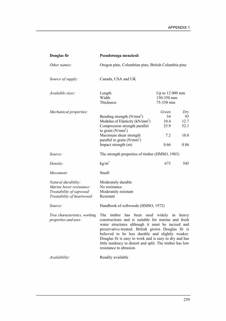
APPENDIX 1
259
Douglas fir Pseudotsuga menziesii
Other names: Oregon pine, Columbian pine, British Columbia pine
Source of supply: Canada, USA and UK
Available sizes: Length Up to 12 000 mmWidth 150-350 mmThickness 75-350 mm
Mechanical properties: Green DryBending strength (N/mm2) 54 93Modulus of Elasticity (kN/mm2) 10.4 12.7Compression strength parallel 25.9 52.1to grain (N/mm2)Maximum shear strength 7.2 10.8parallel to grain (N/mm2)Impact strength (m) 0.66 0.86
Source: The strength properties of timber (HMSO, 1983)
Density: kg/m3 673 545
Movement: Small
Natural durability: Moderately durableMarine borer resistance: No resistanceTreatability of sapwood: Moderately resistantTreatability of heartwood: Resistant
Source: Handbook of softwoods (HMSO, 1972)
Tree characteristics, workingproperties and uses:
The timber has been used widely in heavyconstructions and is suitable for marine and freshwater structures although it must be incised andpreservative-treated. British grown Douglas fir isbelieved to be less durable and slightly weaker.Douglas fir is easy to work and is easy to dry and haslittle tendency to distort and split. The timber has lowresistance to abrasion.
Availability: Readily available

MANUAL ON THE USE OF TIMBER IN COASTAL AND RIVER ENGINEERING
260
Ekki Lophira alata
Other names: Azobe, Kaku, Bongossi
Source of supply: Widespread throughout West and Central Africa
Available sizes: Length Up to 8 000 mmWidth Up to 100-350 mmThickness Up to 75-350 mm
Mechanical properties: Green DryBending strength (N/mm2) 118 164Modulus of Elasticity (kN/mm2) 13.6 16.2Compression strength parallel 65.6 85to grain (N/mm2)Maximum shear strength 15.2 23.5parallel to grain (N/mm2)Impact strength (m) 1.35 1.2
Source: The strength properties of timber (HMSO, 1983)
Density: kg/m3 1292 1051
Movement: Large
Natural durability: Very durableMarine borer resistance: ResistantTreatability of sapwood: Moderately resistantTreatability of heartwood: Extremely resistant
Source: Handbook of hardwoods (HMSO, 1997)
Tree characteristics, workingproperties and uses:
The timber has long been recognised for its excellentproperties for heavy constructions and is used widelythroughout Europe in marine structures. The timberhas excellent resistance to abrasion but is difficult towork and has a tendency to distort and split. Thetimber has a transition zone between the heartwoodand sapwood. This is usually slightly paler than theheartwood. The designer should be aware that thistransition wood is only moderately durable. The tree isreported to reach a height of 55 m with a diameter of1.5-1.8 m. The bole is long and clear.
Availability: Readily available

APPENDIX 1
261
Essia Combretodendron africanum
Other names: Owewe (Nigeria), Minzu (Congo-Brazzaville), Abale(Cote d’Ivoire), Abine (Gabon)
Source of supply: Widespread throughout West Africa
Available sizes: LengthWidthThickness
Mechanical properties: Green DryBending strength (N/mm2) 140Modulus of Elasticity (kN/mm2) 14.5Compression strength parallel 74.9to grain (N/mm2)Maximum shear strength 15.4parallel to grain (N/mm2)Impact strength (m) 1.14
Source: The strength properties of timber (HMSO, 1983)
Density: kg/m3 960 865
Movement: Large
Natural durability: Probably moderately durableMarine borer resistance: Not resistant *Treatability of sapwood: Extremely resistantTreatability of heartwood: Extremely resistant
Source: Handbook of hardwoods (HMSO, 1997)
Tree characteristics, workingproperties and uses:
Prone to degrade when drying. Suitable for rough,heavy construction work. Difficult to work and proneto splitting. The tree is reported to reach a height of37 m or more with a diameter of 0.8-1.1 m. The boleis reasonably straight and cylindrical.
Availability: No reliable records of its use in the UK
*Poor performance against Limnoria spp. during laboratory trials

MANUAL ON THE USE OF TIMBER IN COASTAL AND RIVER ENGINEERING
262
Favinha Enterolobium schoenburgkii
Other names: Batibatra
Source of supply: Brazil, Guyana
Available sizes: LengthWidthThickness
Mechanical properties: Green DryBending strength (N/mm2) 128Modulus of Elasticity (kN/mm2) 14.6Compression strength parallel 66to grain (N/mm2)Maximum shear strengthparallel to grain (N/mm2)Impact strength (m)
Source: Ecotimber handbook
Density: kg/m3 1100 830
Movement:
Natural durability: Very durableMarine borer resistance: Probably not resistant *Treatability of sapwood: Probably resistantTreatability of heartwood: Probably resistant
Source:
Tree characteristics, workingproperties and uses:
Timber is very heavy but works fairly well, requirescare with finishing. It is used for flooring, decking,civil construction, carpentry and joinery.
Availability: Regular supply
*Performed poorly against Limnoria spp. during laboratory screening trials

APPENDIX 1
263
Freijo Cordia goeldiana
Other names: Jenny wood (USA), Cordia wood, Frei jorge (Brazil)
Source of supply: Brazil
Available sizes: LengthWidthThickness
Mechanical properties: Green DryBending strength (N/mm2) 97Modulus of Elasticity (kN/mm2) 12Compression strength parallel 54.3to grain (N/mm2)Maximum shear strength 10.2parallel to grain (N/mm2)Impact strength (m)
Source: The strength properties of timber (HMSO, 1983)
Density: kg/m3 700 585
Movement: n/a
Natural durability: DurableMarine borer resistance: Probably resistantTreatability of sapwood: Probably resistantTreatability of heartwood: Probably resistant
Source: Handbook of hardwoods (HMSO, 1997)
Tree characteristics, workingproperties and uses:
Similar strength properties to Myannmar teak. Easy towork. The tree is reported to reach a height of 30 mwith a diameter of 0.6-1.0 m.
Availability: Poor quality of imports has prevented acceptance ofthe species in the European market. Limitedavailability.
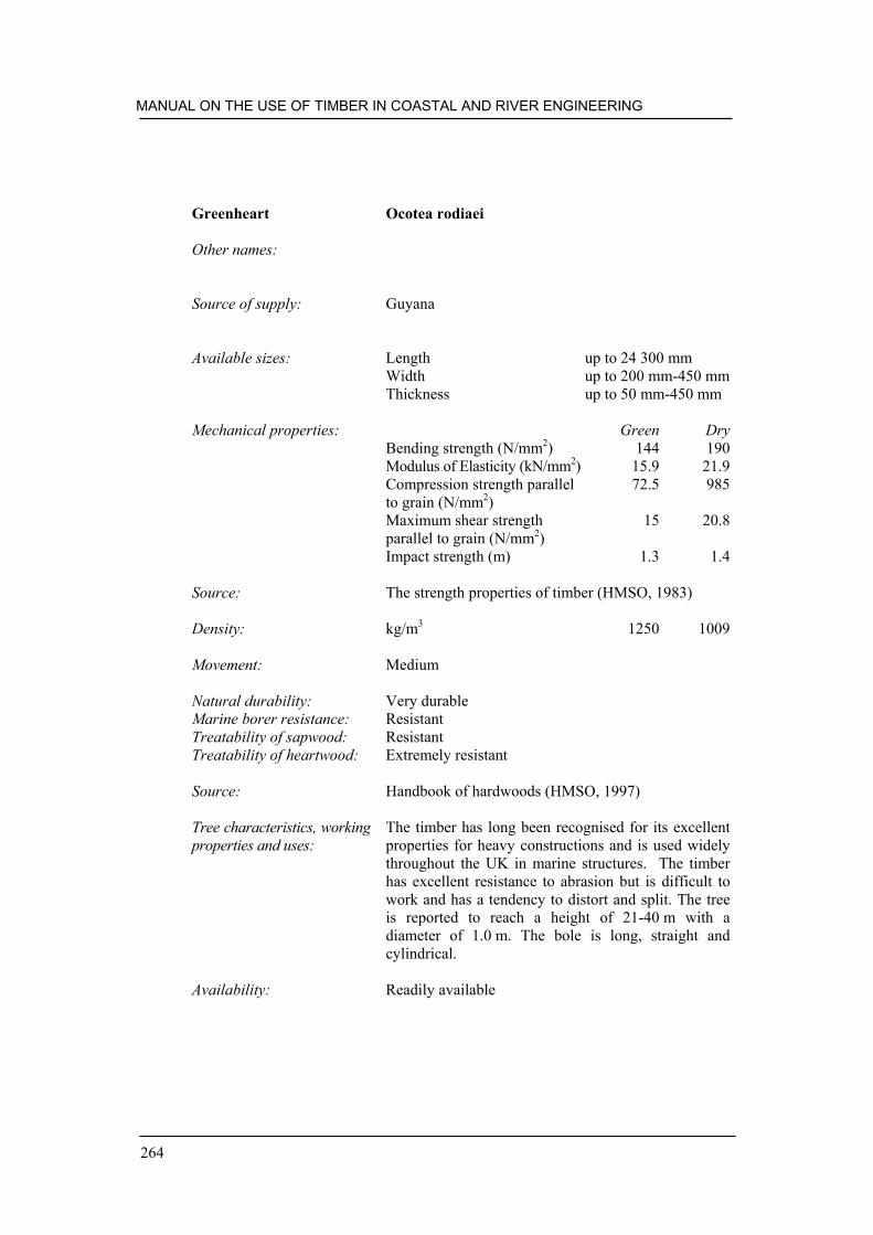
MANUAL ON THE USE OF TIMBER IN COASTAL AND RIVER ENGINEERING
264
Greenheart Ocotea rodiaei
Other names:
Source of supply: Guyana
Available sizes: Length up to 24 300 mmWidth up to 200 mm-450 mmThickness up to 50 mm-450 mm
Mechanical properties: Green DryBending strength (N/mm2) 144 190Modulus of Elasticity (kN/mm2) 15.9 21.9Compression strength parallel 72.5 985to grain (N/mm2)Maximum shear strength 15 20.8parallel to grain (N/mm2)Impact strength (m) 1.3 1.4
Source: The strength properties of timber (HMSO, 1983)
Density: kg/m3 1250 1009
Movement: Medium
Natural durability: Very durableMarine borer resistance: ResistantTreatability of sapwood: ResistantTreatability of heartwood: Extremely resistant
Source: Handbook of hardwoods (HMSO, 1997)
Tree characteristics, workingproperties and uses:
The timber has long been recognised for its excellentproperties for heavy constructions and is used widelythroughout the UK in marine structures. The timberhas excellent resistance to abrasion but is difficult towork and has a tendency to distort and split. The treeis reported to reach a height of 21-40 m with adiameter of 1.0 m. The bole is long, straight andcylindrical.
Availability: Readily available
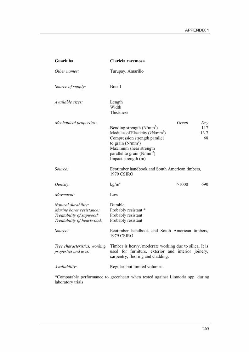
APPENDIX 1
265
Guariuba Claricia racemosa
Other names: Turupay, Amarillo
Source of supply: Brazil
Available sizes: LengthWidthThickness
Mechanical properties: Green DryBending strength (N/mm2) 117Modulus of Elasticity (kN/mm2) 13.7Compression strength parallel 68to grain (N/mm2)Maximum shear strengthparallel to grain (N/mm2)Impact strength (m)
Source: Ecotimber handbook and South American timbers,1979 CSIRO
Density: kg/m3 >1000 690
Movement: Low
Natural durability: DurableMarine borer resistance: Probably resistant *Treatability of sapwood: Probably resistantTreatability of heartwood: Probably resistant
Source: Ecotimber handbook and South American timbers,1979 CSIRO
Tree characteristics, workingproperties and uses:
Timber is heavy, moderate working due to silica. It isused for furniture, exterior and interior joinery,carpentry, flooring and cladding.
Availability: Regular, but limited volumes
*Comparable performance to greenheart when tested against Limnoria spp. duringlaboratory trials

MANUAL ON THE USE OF TIMBER IN COASTAL AND RIVER ENGINEERING
266
Heritiera Heritiera littoralis
Other names: Tulip mangrove
Source of supply: Australia, Papua New Guinea, Malaysia
Available sizes: LengthWidthThickness
Mechanical properties: Green DryBending strength (N/mm2) 73-86 114-134Modulus of Elasticity (kN/mm2) 14.2-16.3Compression strength parallel 62-71to grain (N/mm2)Maximum shear strength 15-16.7parallel to grain (N/mm2)Impact strength (m)
Source: Characteristics, properties and uses of timber. Vol 1.South-East Asia, Northern Australia and the Pacific.CSIRO
Density: kg/m3 725-900
Movement:
Natural durability: Moderately durableMarine borer resistance: Listed as resistant to marine borers *Treatability of sapwood: PermeableTreatability of heartwood: Resistant
Source: Characteristics, properties and uses of timber. Vol 1.South-East Asia, Northern Australia and the Pacific.CSIRO
Tree characteristics, workingproperties and uses:
Timber is hard and strong and difficult to work, due tosilica. The tree may reach 30 m in height with a boleup to 18 m and 0.8-1.3 m diameter. Used for wharfand bridge building, decking, cladding and joinery.
Availability: No information on availability in the UK
* Moderate resistance to Limnoria spp. observed during laboratory trials. Presence ofsilica may offer good resistance to Teredo spp.

APPENDIX 1
267
Ipê Tabebuia spp.
Other names: Iron wood, Groenhart, Ipê tabaco
Source of supply: Central and South America, Caribbean
Available sizes: Length Up to 12 000 mmWidth 225 mm-350 mmThickness 100 mm-350 mm
Mechanical properties: Green DryBending strength (N/mm2) 137Modulus of Elasticity (kN/mm2) 13.9Compression strength parallel 77.6to grain (N/mm2)Maximum shear strength 19.4parallel to grain (N/mm2)Impact strength (m)
Source: The strength properties of timber (HMSO, 1983)
Density: kg/m3 1300 1050
Movement: Medium
Natural durability: Very durableMarine borer resistance: Probably resistant *Treatability of sapwood: PermeableTreatability of heartwood: Extremely resistant
Source: Handbook of hardwoods (HMSO, 1997)
Tree characteristics, workingproperties and uses:
Timber is very heavy, durable and strong, needingpre-drilling for nailing. It is used for flooring, decking,heavy and outdoor construction, jetties, sea defences.
Availability: Regular in limited volumes
*Good resistance against Limnoria spp. observed during laboratory trials

MANUAL ON THE USE OF TIMBER IN COASTAL AND RIVER ENGINEERING
268
Itauba Mezilaurus itauba
Other names: Itauba amarela, Itauba abacate, Itauba preta
Source of supply: Brazil
Available sizes: LengthWidthThickness
Mechanical properties: Green DryBending strength (N/mm2) 124Modulus of Elasticity (kN/mm2) 16.2Compression strength parallel 62to grain (N/mm2)Maximum shear strengthparallel to grain (N/mm2)Impact strength (m)
Source: Ecotimber handbook
Density: kg/m3 1070 750-1000
Movement: Large
Natural durability: Very durableMarine borer resistance: ResistantTreatability of sapwood: Probably resistantTreatability of heartwood: Probably resistant
Source: Ecotimber handbook
Tree characteristics, workingproperties and uses:
The timber has been used for marine construction inBrazil. The tree reaches a height of 40-50 m with abole of 10-30 m of diameter 1.5 m. The bole may becylindrical or buttressed.
Availability: No information on availability in the UK

APPENDIX 1
269
Jarana Lecythis spp.
Other names:
Source of supply: Brazil
Available sizes: LengthWidthThickness
Mechanical properties: Green DryBending strength (N/mm2) 152Modulus of Elasticity (kN/mm2) 15.6Compression strength parallel 82to grain (N/mm2)Maximum shear strengthparallel to grain (N/mm2)Impact strength (m)
Source: Ecotimber handbook
Density: kg/m3 1200 850-950
Movement: Large
Natural durability: Very durableMarine borer resistance: Probably not resistant *Treatability of sapwood: Probably resistantTreatability of heartwood: Probably resistant
Source: Ecotimber handbook
Tree characteristics, workingproperties and uses:
A small tree reaching heights of 20 m.
Availability: No information on availability in the UK
*Performed poorly in laboratory trials when challenged with Limnoria spp.

MANUAL ON THE USE OF TIMBER IN COASTAL AND RIVER ENGINEERING
270
Jarrah Eucalyptus marginata
Other names:
Source of supply: South Western Australia
Available sizes: Length 5 700 mmWidth 75 mm-300 mmThickness 50 mm-300 mm
Mechanical properties: Green DryBending strength (N/mm2) 72 118Modulus of Elasticity (kN/mm2) 9.6 12.1Compression strength parallel 37.2 63.5to grain (N/mm2)Maximum shear strength 10.3 16.7parallel to grain (N/mm2)Impact strength (m) n/a n/a
Source: The strength properties of timber (HMSO, 1983)
Density: kg/m3 1009 865
Movement:
Natural durability: Very durableMarine borer resistance: ResistantTreatability of sapwood: n/aTreatability of heartwood: Extremely resistant
Source: Handbook of hardwoods (HMSO, 1997)
Tree characteristics, workingproperties and uses:
Difficult to work and to nail, pre-boring necessary,holds screws well. This timber has a tendency todistort or split and has medium resistance to abrasion.The tree is reported to reach a height of 30-45 m witha diameter of 1.0 m-1.5 m.
Availability: Readily available

APPENDIX 1
271
Kapur Drylobalanops spp.
Other names:
Source of supply: South East Asia, principally Malaysia and Indonesia
Available sizes: Length 3 000 mm-9 000 mmWidth 50 mm-300 mmThickness 50 mm-300 mm
Mechanical properties: Green DryBending strength (N/mm2) 81 117Modulus of Elasticity (kN/mm2) 10.9 13.0Compression strength parallel 41.2 69.6to grain (N/mm2)Maximum shear strength 8.5parallel to grain (N/mm2)Impact strength (m) 0.71
Source: Handbook of hardwoods (HMSO, 1997)
Density: kg/m3 865 700
Movement: Medium
Natural durability: Very durableMarine borer resistance: Probably resistantTreatability of sapwood: PermeableTreatability of heartwood: Extremely resistant
Source: Handbook of hardwoods (HMSO, 1997)
Tree characteristics, workingproperties and uses:
A number of Drylobalanops species are grouped underthe commercial description of ‘kapur’. The timber iscoarse but straight grained. In the green state, kapur isslightly superior in terms of strength than myannmar.The tree is reported to reach a height of 60 m orsometimes more with a diameter of 1.0 m-1.5 m.
Availability: No information on availability in the UK. Supplies areplentiful in S.E. Asia. Possible to procure byarrangement with shipper through timber importer.

MANUAL ON THE USE OF TIMBER IN COASTAL AND RIVER ENGINEERING
272
Karri Eucalyptus diversicolor
Other names:
Source of supply: South Western Australia
Available sizes: Length Up to 8 500 mmWidth 75 mm-300 mmThickness 50 mm-300 mm
Mechanical properties: Green DryBending strength (N/mm2) 77 139Modulus of Elasticity (kN/mm2) 13.4 17.9Compression strength parallel 37.6 74.5to grain (N/mm2)Maximum shear strength 10.4 16.7parallel to grain (N/mm2)Impact strength (m) n/a n/a
Source: The strength properties of timber (HMSO, 1983)
Density: kg/m3 1041 913
Movement:
Natural durability: DurableMarine borer resistance: Probably not resistantTreatability of sapwood: Probably resistantTreatability of heartwood: Extremely resistant
Source: Handbook of hardwoods (HMSO, 1997)
Tree characteristics, workingproperties and uses:
Difficult to work and to nail, pre-boring necessary.This timber has a tendency to distort or split and hasmedium resistance to abrasion. Little reported use aspilings. The tree is reported to reach a height of 45-60 m or sometimes larger with a diameter of 1.8-3.0 m. The bole is clear.
Availability: Readily available

APPENDIX 1
273
Kauta/ Kautaballi/Marish Licania spp.
Other names: Marish-marishballi (Guyana), Anaura (Brazil),Kauston (Surinam), Gris-gris (French Guiana), Boisgalettes (French Guiana)
Source of supply: Guyana, Surinam, French Guiana, Brazil
Available sizes: LengthWidthThickness
Mechanical properties: Green DryBending strength (N/mm2)Modulus of Elasticity (kN/mm2)Compression strength parallelto grain (N/mm2)Maximum shear strengthparallel to grain (N/mm2)Impact strength (m)
Density: kg/m3 1150-1460 930-1280
Movement:
Natural durability: Moderately durableMarine borer resistance: ResistantTreatability of sapwood: ResistantTreatability of heartwood: Resistant
Source: South American timbers 1979, CSIRO
Tree characteristics, workingproperties and uses:
At least nine species comprise the species groupKauta, Kautaballi and Marish. The timbers are allsimilar in that they are hard, heavy and strong. Highsilica content. The timber has long been recognisedfor its resistance to marine borers and in trials in theUSA, they outperformed greenheart, manbarklak andbasralocus. The timber is thought to be comparable togreenheart for strength, although inferior in terms ofimpact resistance.
Availability: No information although thought to be plentiful insupply from South America by prior arrangement withimporter.

MANUAL ON THE USE OF TIMBER IN COASTAL AND RIVER ENGINEERING
274
Keledang Artocarpus spp.
Other names:
Source of supply: South East Asia, principally Malaysia and Indonesia
Available sizes: LengthWidthThickness
Mechanical properties: Green DryBending strength (N/mm2)Modulus of Elasticity (kN/mm2)Compression strength parallelto grain (N/mm2)Maximum shear strengthparallel to grain (N/mm2)Impact strength (m)
Source: Timbers of the world (TRADA)
Density: kg/m3 680-960 560-800
Movement:
Natural durability: Moderately durableMarine borer resistance: Probably resistantTreatability of sapwood: Probably resistantTreatability of heartwood: Probably resistant
Source:
Tree characteristics, workingproperties and uses:
Used for heavy constructions. Strength varies becauseof variation of species that comprise keledang but isbelieved to be similar to that of kapur. Timber hasdeep interlocked grain and a coarse texture.
Availability: No information on availability in the UK. Supplies areplentiful in S.E. Asia. Possible to procure byarrangement with shipper through timber importer.

APPENDIX 1
275
Kempas Koompassia malaccensis
Other names: Mengeris, Tualang
Source of supply: Malaysia, Indonseia
Available sizes: Length 3 000 mmWidth 150 mmThickness 50 mm
Mechanical properties: Green DryBending strength (N/mm2) 105 128Modulus of Elasticity (kN/mm2) 15.66 18.6Compression strength parallel 56.7 68.1to grain (N/mm2)Maximum shear strengthparallel to grain (N/mm2)Impact strength (m)
Source: Handbook of hardwoods (HMSO, 1997)
Density: kg/m3 1024-1100 770-1000
Movement:
Natural durability: DurableMarine borer resistance: ResistantTreatability of sapwood: Probably resistantTreatability of heartwood: Resistant
Source: Handbook of hardwoods (HMSO, 1997)
Tree characteristics, workingproperties and uses:
Works well but has a tendency to blunt cutters andsaws. Difficult to nail. Little reported use as pilings.The tree is reported to reach a height of 55 m. Thebole is columnar, with large buttresses.
Availability: Limited in the UK

MANUAL ON THE USE OF TIMBER IN COASTAL AND RIVER ENGINEERING
276
Keranji Dialum spp.
Other names: Malaysia
Source of supply: Malaysia
Available sizes: LengthWidthThickness
Mechanical properties: Green DryBending strength (N/mm2)Modulus of Elasticity (kN/mm2)Compression strength parallelto grain (N/mm2)Maximum shear strengthparallel to grain (N/mm2)Impact strength (m)
Source:
Density: kg/m3
Movement:
Natural durability: Moderately durableMarine borer resistance: Probably resistantTreatability of sapwood: Probably resistantTreatability of heartwood: Probably resistant
Source: Timbers if the world (TRADA)
Tree characteristics, workingproperties and uses:
Keranji is a commercial description applied to a rangeof dialum species with similar properties. Keranji is atough, hard, dense timber suitable for heavyconstruction. It is difficult to work.
Availability: No information on availability in the UK. Supplies areplentiful in S.E. Asia. Possible to procure byarrangement with shipper through timber importer.

APPENDIX 1
277
Keruing Dipterocarpus spp.
Other names: Gurjun, Yang, Apitong, Eng
Source of supply: Malaysia, Indonesia, Philippines, Vietnam, Myannmar,Laos, Cambodia
Available sizes: Length up to 7 600 mmWidth 50 mm-100 mm (sometimes wider)Thickness 25 mm-100 mm (sometimes thicker)
Mechanical properties: Green DryBending strength (N/mm2) 70-83 110-144Modulus of Elasticity (kN/mm2) 11.8-16.0 13.7-17.6Compression strength parallel 35.4-43.1 59.6-79.8to grain (N/mm2)Maximum shear strength 7.2-8.1 12.2-14.3parallel to grain (N/mm2)Impact strength (m) 0.69-0.81 0.97-1.09
Source: The strength properties of timber (HMSO, 1983)
Density: kg/m3 753-929 641-849
Movement:
Natural durability: Moderately durableMarine borer resistance: Probably not resistantTreatability of sapwood: Probably resistantTreatability of heartwood: Variable – moderately
resistant
Source: Handbook of hardwoods (HMSO, 1997)
Tree characteristics, workingproperties and uses:
Variable timber, but works relatively well. Pre-boreprior to nailing. Tendency to distort on drying. Littlereported use as pilings. Medium to high resistance toabrasion. The tree is reported to reach a height of 30-60 m with a diameter of 1.0-1.8 m. The bole isreasonably straight and clear.
Availability: Readily available

MANUAL ON THE USE OF TIMBER IN COASTAL AND RIVER ENGINEERING
278
Kopie Goupia glabra
Other names: Kabukalli, Cupiuba (Brazil), Goupi (Guyana), Kopie(Surinam)
Source of supply: South America
Available sizes: LengthWidthThickness
Mechanical properties: Green DryBending strength (N/mm2) 122Modulus of Elasticity (kN/mm2) 14.7Compression strength parallel 62to grain (N/mm2)Maximum shear strengthparallel to grain (N/mm2)Impact strength (m)
Source: Ecotimber handbook
Density: kg/m3 832
Movement:
Natural durability: DurableMarine borer resistance: Probably not resistantTreatability of sapwood: Probably resistantTreatability of heartwood: Probably resistant
Source: Ecotimber handbook
Tree characteristics, workingproperties and uses:
Reported to be suitable for heavy constructions inwater free of Teredo. Kopie is a hard strong timberbut, for its density, has lower impact resistance thanwould be expected. The tree reaches a height of 30-40 m with a bole length of 10-30 m and diameter up to1.5 m. The bole is buttressed.
Availability: Limited supplies, Sizes and volumes should beconfirmed prior to procurement.

APPENDIX 1
279
Larch Larix spp.
Other names: European, Japanese, Dunkeld/Hybrid larch
Source of supply: Mostly UK and some Europe
Available sizes: Length Up to 9 000 mmWidth Up to 250 mmThickness Up to 250 mm
Mechanical properties: Green DryBending strength (N/mm2) 43-53 77-92Modulus of Elasticity (kN/mm2) 5.9-6.8 8.5-9.9Compression strength parallel 19.2-24.3 39.1-46.7to grain (N/mm2)Maximum shear strength 5.9-6.9 11.6-12.4parallel to grain (N/mm2)Impact strength (m) 0.69-0.86 0.64-0.76
Source: The strength properties of timber (HMSO, 1983)
Density: kg/m3 580-670 460-540
Movement:
Natural durability: Moderately durableMarine borer resistance: Probably not resistantTreatability of sapwood: Moderately resistantTreatability of heartwood: Resistant
Source: Handbook of softwoods (HMSO, 1972)
Tree characteristics, workingproperties and uses:
Relatively easy to work, may split on nailing. Lowresistance to abrasion.
Availability: Readily available

MANUAL ON THE USE OF TIMBER IN COASTAL AND RIVER ENGINEERING
280
Louro Gamela Nectandra rubra
Other names: Louro vermelho, Red louro
Source of supply: Brazil
Available sizes: LengthWidthThickness
Mechanical properties: Green DryBending strength (N/mm2) 90Modulus of Elasticity (kN/mm2) 11.4Compression strength parallel 51to grain (N/mm2)Maximum shear strengthparallel to grain (N/mm2)Impact strength (m)
Source: Ecotimber handbook
Density: kg/m3 1000 660
Movement:
Natural durability: DurableMarine borer resistance: Probably resistant *Treatability of sapwood: Moderately resistantTreatability of heartwood: Extremely resistant
Source: Timbers of the world (TRADA)
Tree characteristics, workingproperties and uses:
Timber is medium to heavy, but works fairly well. Itis used for decking, shipbuilding, interior and exteriorjoinery, cladding.
Availability: Regular in large volumes
*Good resistance to Limnoria spp. observed during laboratory trials

APPENDIX 1
281
Louro Itauba Mezilaurus itauba
Other names: Louro itauba
Source of supply: South America
Available sizes: LengthWidthThickness
Mechanical properties: Green DryBending strength (N/mm2) 124Modulus of Elasticity (kN/mm2) 16.2Compression strength parallel 62to grain (N/mm2)Maximum shear strengthparallel to grain (N/mm2)Impact strength (m)
Source: Ecotimber handbook
Density: kg/m3 1070 855
Movement: Reported to be low
Natural durability: Very durableMarine borer resistance: Probably not resistant *Treatability of sapwood: Probably resistantTreatability of heartwood: Extremely resistant
Source: Ecotimber handbook
Tree characteristics, workingproperties and uses:
Timber is very heavy, but works fairly well. It is usedfor flooring, decking, heavy and hydraulicconstruction interior and exterior joinery, cladding.
Availability: Regular in moderate volumes
*Performed poorly in laboratory trials when challenged with Limnoria spp.

MANUAL ON THE USE OF TIMBER IN COASTAL AND RIVER ENGINEERING
282
Louro Preto Ocotea fagantissima
Other names: Silverballi
Source of supply: Brazil
Available sizes: LengthWidthThickness
Mechanical properties: Green DryBending strength (N/mm2) 89Modulus of Elasticity (kN/mm2) 11.0Compression strength parallel 49to grain (N/mm2)Maximum shear strengthparallel to grain (N/mm2)Impact strength (m)
Source: Ecotimber handbook
Density: kg/m3 900 540
Movement: Low
Natural durability: Moderately durable – durableMarine borer resistance: Little resistance to marine borers *Treatability of sapwood: Probably resistantTreatability of heartwood: Resistant
Source: Ecotimber handbook
Tree characteristics, workingproperties and uses:
Timber is medium heavy, but works fairly well,machining may be difficult due to interlocked grain. Itis used for flooring and decking, interior and exteriorjoinery, cladding.
Availability: Regular
*Performed poorly in laboratory trials when challenged with Limnoria spp.

APPENDIX 1
283
Manbarklak Escweilera spp.
Other names: Kakaralli (Guyana)
Source of supply: Surinam, Guyana and to a lesser extent, West Indies,Caribbean
Available sizes: Length 3600 mm-7200 mmWidth up to 225 mmThickness up to 225 mm
Mechanical properties: Green DryBending strength (N/mm2)Modulus of Elasticity (kN/mm2)Compression strength parallelto grain (N/mm2)Maximum shear strengthparallel to grain (N/mm2)Impact strength (m)
Source:
Density: kg/m3 1200 1050
Movement: n/a
Natural durability: DurableMarine borer resistance: Probably resistantTreatability of sapwood: Extremely resistantTreatability of heartwood: Extremely resistant
Source: Timbers of the world (TRADA)
Tree characteristics, workingproperties and uses:
About 80 species of Escweilera spp. are to be found inthe Caribbean and South America although fewcontribute to timber marketed as manbarklak.Manbarklak is extremely hard, tough and strong andhas good abrasion resistance. It improves in strengthconsiderably during drying and compares favourablywith greenheart although it is inferior in terms ofstiffness and tension across the grain. Nevertheless,manbarklak has excellent impact resistance.
Availability: Limited supplies in the UK although good supplies inSouth America. Sizes and volumes should beconfirmed prior to procurement.

MANUAL ON THE USE OF TIMBER IN COASTAL AND RIVER ENGINEERING
284
Mangrove cedars Xylocarpus granatum & X. Australasicum
Other names: Cedar mangrove
Source of supply: Papua New Guinea, Australia, Burma, Philippines
Available sizes: LengthWidthThickness
Mechanical properties: Green DryBending strength (N/mm2) 43-62 67-94Modulus of Elasticity (kN/mm2) 9.1-12.4Compression strength parallel 40-53to grain (N/mm2)Maximum shear strength 10.3-13.1parallel to grain (N/mm2)Impact strength (m)
Source: Characteristics, properties and uses of timber. Vol 1.South-East Asia, Northern Australia and the Pacific.CSIRO
Density: kg/m3 575-640
Movement:
Natural durability: Moderately durableMarine borer resistance: Reported resistant to Teredo spp.*Treatability of sapwood: Probably resistantTreatability of heartwood: Probably resistant
Source:
Tree characteristics, workingproperties and uses:
Timber works easily with all tools. The tree may reach15-20 m in height with a short straight bole up to 10 mand 0.8 m diameter. Used for salt-water piling, oarsand sliced veneer.
Availability: No information on availability in the UK
*Similar performance to greenheart when challenged with Limnoria spp. underlaboratory conditions

APPENDIX 1
285
Massaranduba Manilkara spp.
Other names: Bolletri, Bullet wood, Balata rouge
Source of supply: Brazil, French Guyana, Surinam
Available sizes: Length Up to 12 000 mmWidth Up to 350 mmThickness Up to 350 mm
Mechanical properties: Green DryBending strength (N/mm2) 154 n/aModulus of Elasticity (kN/mm2) 20.6 n/aCompression strength parallel 75.7 n/ato grain (N/mm2)Maximum shear strength 17.3 n/aparallel to grain (N/mm2)Impact strength (m) n/a n/a
Source: Ecotimber handbook
Density: kg/m3 1120-1400 930-1161
Movement:
Natural durability: Very durableMarine borer resistance: Probably resistantTreatability of sapwood: Probably resistantTreatability of heartwood: Probably resistant
Source: Handbook of hardwoods (HMSO, 1997)
Tree characteristics, workingproperties and uses:
Difficult to work. Screws and nails well with pre-boring. High resistance to abrasion.
Availability: Available

MANUAL ON THE USE OF TIMBER IN COASTAL AND RIVER ENGINEERING
286
Mecrusse Androstachys johnsonii
Other names:
Source of supply: Mozambique and Zimbabwe
Available sizes: LengthWidthThickness
Mechanical properties: Green DryBending strength (N/mm2)Modulus of Elasticity (kN/mm2)Compression strength parallelto grain (N/mm2)Maximum shear strengthparallel to grain (N/mm2)Impact strength (m)
Source:
Density: kg/m3 1200 1000
Movement: Medium
Natural durability: Very durableMarine borer resistance: Probably resistantTreatability of sapwood: Extremely resistantTreatability of heartwood: Extremely resistant
Source: Timbers of the world (TRADA)
Tree characteristics, workingproperties and uses:
A tall straight tree, height up to 36 m, averagediameter up to 0.5 m.
Availability: No information on availability in the UK
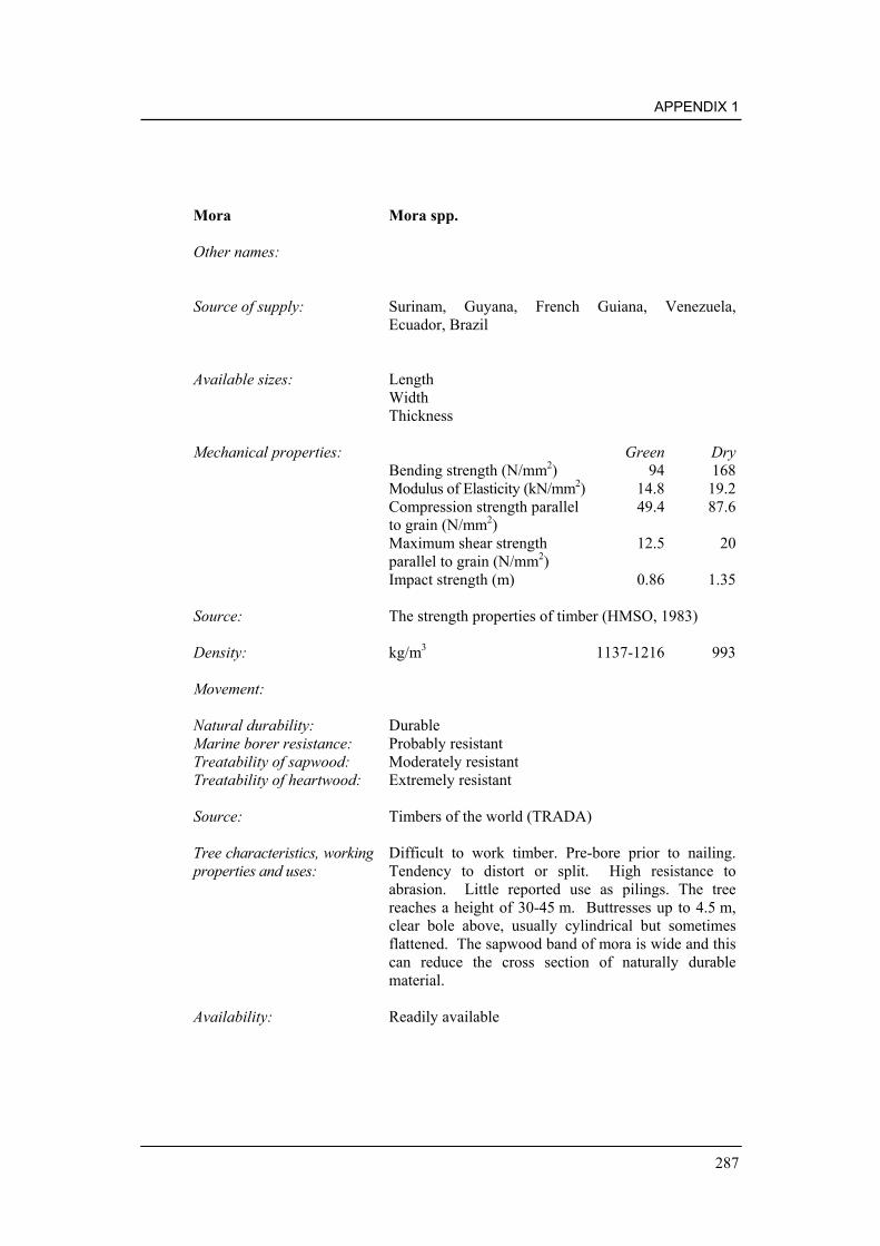
APPENDIX 1
287
Mora Mora spp.
Other names:
Source of supply: Surinam, Guyana, French Guiana, Venezuela,Ecuador, Brazil
Available sizes: LengthWidthThickness
Mechanical properties: Green DryBending strength (N/mm2) 94 168Modulus of Elasticity (kN/mm2) 14.8 19.2Compression strength parallel 49.4 87.6to grain (N/mm2)Maximum shear strength 12.5 20parallel to grain (N/mm2)Impact strength (m) 0.86 1.35
Source: The strength properties of timber (HMSO, 1983)
Density: kg/m3 1137-1216 993
Movement:
Natural durability: DurableMarine borer resistance: Probably resistantTreatability of sapwood: Moderately resistantTreatability of heartwood: Extremely resistant
Source: Timbers of the world (TRADA)
Tree characteristics, workingproperties and uses:
Difficult to work timber. Pre-bore prior to nailing.Tendency to distort or split. High resistance toabrasion. Little reported use as pilings. The treereaches a height of 30-45 m. Buttresses up to 4.5 m,clear bole above, usually cylindrical but sometimesflattened. The sapwood band of mora is wide and thiscan reduce the cross section of naturally durablematerial.
Availability: Readily available

MANUAL ON THE USE OF TIMBER IN COASTAL AND RIVER ENGINEERING
288
Muiracatiara Astronium lecontei/graveolens/fraxinifolium
Other names: Gonçalo Alves, Zebrawood, Tigerwood
Source of supply: Brazil
Available sizes: LengthWidthThickness
Mechanical properties: Green DryBending strength (N/mm2) 133Modulus of Elasticity (kN/mm2) 17.1Compression strength parallel 76to grain (N/mm2)Maximum shear strengthparallel to grain (N/mm2)Impact strength (m)
Source: Ecotimber handbook
Density: kg/m3 1100 880
Movement:
Natural durability: Very durableMarine borer resistance: Probably moderately resistant *Treatability of sapwood: Probably resistantTreatability of heartwood: Extremely resistant
Source: Ecotimber handbook
Tree characteristics, workingproperties and uses:
The timber is very heavy, but works fairly well, itdoes require pre-drilling for nailing. It is used forflooring, decking, civil and marine construction,interior and exterior joinery.
Availability: Regular
*Similar performance to greenheart when challenged with Limnoria spp. underlaboratory conditions

APPENDIX 1
289
Muninga Pterocarpus angolensis
Other names: Mninga (Tanzania), Ambila (Mozambique), Mukwa(Zambia and Zimbabwe), Kiaat, Kajat, Kajahout (S.Africa)
Source of supply: South and Central Africa
Available sizes: LengthWidthThickness
Mechanical properties: Green DryBending strength (N/mm2) 85 94Modulus of Elasticity (kN/mm2) 7.6 8.4Compression strength parallel 40.6 57.1to grain (N/mm2)Maximum shear strengthparallel to grain (N/mm2)Impact strength (m)
Source:
Density: kg/m3 1073 500-780
Movement: Small
Natural durability: Very durableMarine borer resistance: Probably resistantTreatability of sapwood: Extremely resistantTreatability of heartwood: Extremely resistant
Source: Handbook of hardwoods (HMSO, 1997)
Tree characteristics, workingproperties and uses:
Reported to have excellent properties for marineconstructions. The tree is relatively small, thereforelong large sections are difficult to procure. The treegrows to a height of 21 m, but usually 15 m, with abole length of 4-8 m and diameter about 0.6 m.
Availability: No information on availability in the UK

MANUAL ON THE USE OF TIMBER IN COASTAL AND RIVER ENGINEERING
290
Muhuhu Brachylaena lutchinsii
Other names: Muhugwe (Tanzania)
Source of supply: Tanzania and Kenya
Available sizes: LengthWidthThickness
Mechanical properties: Green DryBending strength (N/mm2) 92 112Modulus of Elasticity (kN/mm2) 8.6 10.1Compression strength parallel 53.6 70.3to grain (N/mm2)Maximum shear strengthparallel to grain (N/mm2) 17.4 23.4Impact strength (m) 0.69 0.56
Source:
Density: kg/m3 1200 880
Movement: Small
Natural durability: Very durableMarine borer resistance: Probably resistantTreatability of sapwood: Extremely resistantTreatability of heartwood: Extremely resistant
Source: The strength properties of timber (HMSO, 1983)
Tree characteristics, workingproperties and uses:
The tree is ‘medium’ sized, therefore it is difficult toobtain large section sizes. The timber is hard anddense, difficult to work but has excellent resistance toabrasion. The tree reaches a height of 25 m, butcommonly only 9-18 m with a fluted and twisted bolelength of 2-6 m, and diameter of 0.5-0.6 m.
Availability: Limited

APPENDIX 1
291
Oak Quercus spp.
Other names:
Source of supply: UK and Europe
Available sizes: Length Up to 7 600 mmWidth Up to 300 mmThickness Up to 300 mm
Mechanical properties: Green DryBending strength (N/mm2) 59 97Modulus of Elasticity (kN/mm2) 8.3 10.1Compression strength parallel 27.6 51.6to grain (N/mm2)Maximum shear strength 9.1 13.7parallel to grain (N/mm2)Impact strength (m) 0.86 0.84
Source: The strength properties of timber (HMSO, 1983)
Density: kg/m3 670-720
Movement:
Natural durability: Very durableMarine borer resistance: Not resistantTreatability of sapwood: PermeableTreatability of heartwood: Resistant
Source: Handbook of hardwoods (HMSO, 1997)
Tree characteristics, workingproperties and uses:
Relatively easy to work and screws and nails well –pre-boring will probably be necessary. Tendency todistort and especially splitting. The tree reaches aheight of 30 m with a bole length of 12-35 m anddiameter 0.9-1.2 m.
Availability: Readily available

MANUAL ON THE USE OF TIMBER IN COASTAL AND RIVER ENGINEERING
292
Opepe Nauclea diderrichii
Other names: Kussia, Bilinga, Badi
Source of supply: West Africa
Available sizes: Length Up to 9 000 mmWidth Up to 350 mmThickness Up to 350 mm
Mechanical properties: Green DryBending strength (N/mm2) 94 120Modulus of Elasticity (kN/mm2) 11.9 13.4Compression strength parallel 51.6 71.7to grain (N/mm2)Maximum shear strength 13.1 17.7parallel to grain (N/mm2)Impact strength (m) 0.81 0.71
Source: The strength properties of timber (HMSO, 1983)
Density: kg/m3 945 753
Movement: Small
Natural durability: Very durableMarine borer resistance: ResistantTreatability of sapwood: PermeableTreatability of heartwood: Moderately resistant
Source: The strength properties of timber (HMSO, 1983)
Tree characteristics, workingproperties and uses:
Moderately easy timber to work but may split whennailed, pre-boring is necessary. Medium to highabrasion resistance. The tree reaches a height of 50 mwith a bole length of 25-30 m and diameter up to1.5 m. The bole is long and cylindrical.
Availability: Readily available
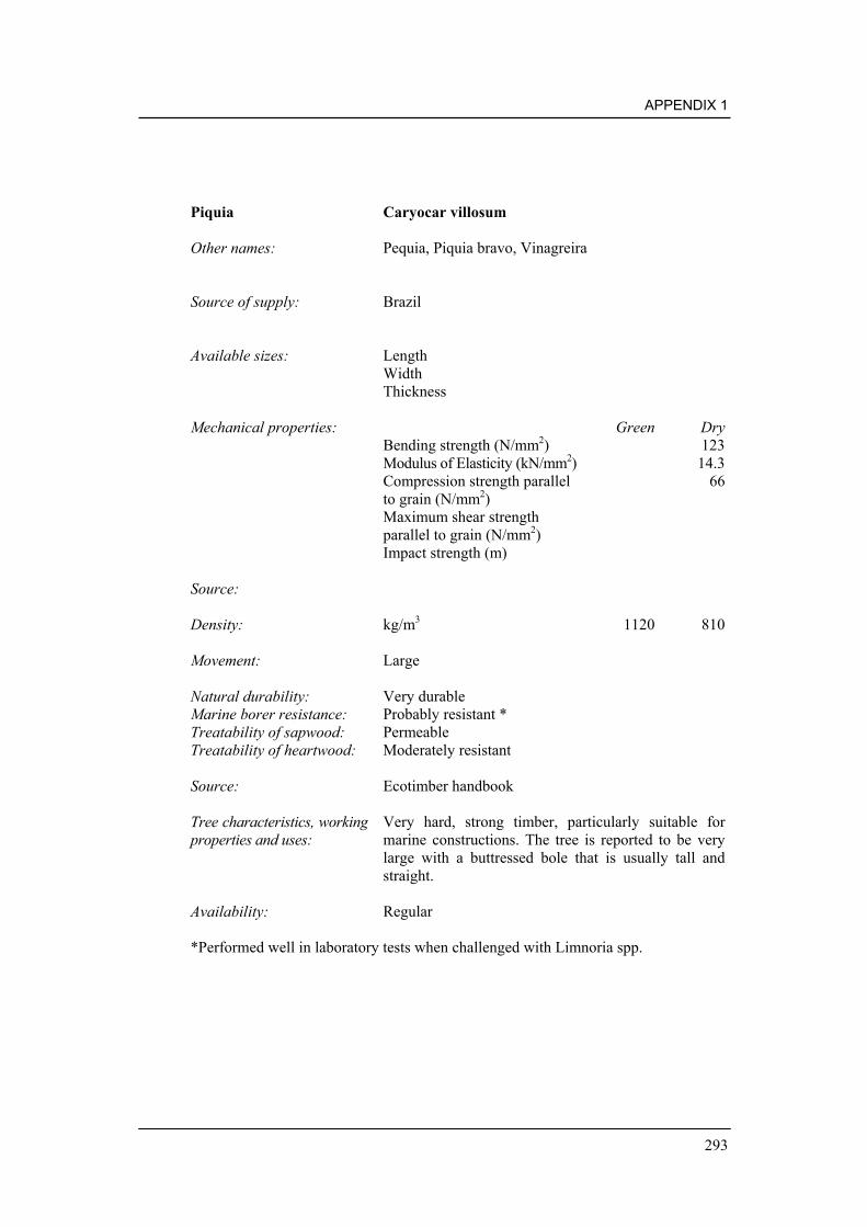
APPENDIX 1
293
Piquia Caryocar villosum
Other names: Pequia, Piquia bravo, Vinagreira
Source of supply: Brazil
Available sizes: LengthWidthThickness
Mechanical properties: Green DryBending strength (N/mm2) 123Modulus of Elasticity (kN/mm2) 14.3Compression strength parallel 66to grain (N/mm2)Maximum shear strengthparallel to grain (N/mm2)Impact strength (m)
Source:
Density: kg/m3 1120 810
Movement: Large
Natural durability: Very durableMarine borer resistance: Probably resistant *Treatability of sapwood: PermeableTreatability of heartwood: Moderately resistant
Source: Ecotimber handbook
Tree characteristics, workingproperties and uses:
Very hard, strong timber, particularly suitable formarine constructions. The tree is reported to be verylarge with a buttressed bole that is usually tall andstraight.
Availability: Regular
*Performed well in laboratory tests when challenged with Limnoria spp.

MANUAL ON THE USE OF TIMBER IN COASTAL AND RIVER ENGINEERING
294
Piquia Marfim Aspidosperma desmathum
Other names: Araracanga, Shibadan
Source of supply: Brazil
Available sizes: LengthWidthThickness
Mechanical properties: Green DryBending strength (N/mm2) 172Modulus of Elasticity (kN/mm2) 20.9Compression strength parallel 91to grain (N/mm2)Maximum shear strengthparallel to grain (N/mm2)Impact strength (m)
Source: Ecotimber handbook
Density: kg/m3 1000 770
Movement:
Natural durability: Very durableMarine borer resistance: Probably not resistant *Treatability of sapwood: Probably resistantTreatability of heartwood: Probably resistant
Source: Ecotimber handbook
Tree characteristics, workingproperties and uses:
Timber is heavy, but works fairly well, and pre-drilling required. It is used for flooring and decking,civil construction, truck floors and tool handles.
Availability: Regular
*Performed poorly in laboratory tests when challenged with Limnoria spp.

APPENDIX 1
295
Pitch pine Pinus caribaea, P. palustris, P. elliotti
Other names: American/Caribbean, etc. pitch pine according toorigin
Source of supply: Caribbean, South East United States
Available sizes: Length Up to 10 600 mmWidth Up to 500 mmThickness Up to 500 mm
Mechanical properties: Green DryBending strength (N/mm2) 66-83 107Modulus of Elasticity (kN/mm2) 10.4-11.4 12.6Compression strength parallel 33-37.4 56.1to grain (N/mm2)Maximum shear strength 9.2-9.9 14.3parallel to grain (N/mm2)Impact strength (m) 0.99-1.04 0.91
Source: The strength properties of timber (HMSO, 1983)
Density: kg/m3 977 769
Movement:
Natural durability: Moderately durableMarine borer resistance: Probably not resistantTreatability of sapwood: PermeableTreatability of heartwood: Moderately resistant
Source: Handbook of softwoods (HMSO, 1972)
Tree characteristics, workingproperties and uses:
Moderately difficult timber to work due to thepresence of resins. Pre-boring may be necessary.Tendency to distort or split.
Availability: Available

MANUAL ON THE USE OF TIMBER IN COASTAL AND RIVER ENGINEERING
296
Purpleheart Peltogyne spp.
Other names: Amaranth
Source of supply: Brazil, Surinam, French Guiana, Guyana
Available sizes: Length Up to 9 000 mmWidth Up to 300 mmThickness Up to 300 mm
Mechanical properties: Green DryBending strength (N/mm2) 105 147Modulus of Elasticity (kN/mm2) 14 16.7Compression strength parallel 56.5 78.5to grain (N/mm2)Maximum shear strength 14.9 18.9parallel to grain (N/mm2)Impact strength (m) 1.04 1.19
Source: The strength properties of timber (HMSO, 1983)
Density: kg/m3
Movement:
Natural durability: DurableMarine borer resistance: Moderately durable *Treatability of sapwood: PermeableTreatability of heartwood: Extremely resistant
Source: Handbook of hardwoods (HMSO, 1997)
Tree characteristics, workingproperties and uses:
Difficult timber to work. Pre-boring may benecessary. Tendency to split, especially when nailed.This timber has high resistance to abrasion. The treecommonly reaches a height of 38-45 m and diameterup to 1.5 m, more usually 0.6-0.9 m. Long lengthshave a tendency to be sprung or exhibit bowingcharacteristics after being sawn. This is attributed toreaction wood as the tree can grow very tall. It isrecommended not to use the timber in very longlengths to avoid any problems caused by spring/bow.
Availability: Readily available
*Out-performed greenheart when challenged with Limnoria spp. under laboratoryconditions

APPENDIX 1
297
Pyinkado Xylia xylocarpa.
Other names: Pyin, Pran, Pkhay, Irul
Source of supply: Myannmar and India
Available sizes: LengthWidthThickness
Mechanical properties: Green DryBending strength (N/mm2) 113 145Modulus of Elasticity (kN/mm2) 14.6 16.1Compression strength parallel 57.4 79.5to grain (N/mm2)Maximum shear strengthparallel to grain (N/mm2)Impact strength (m)
Source: Handbook of hardwoods (HMSO, 1997)
Density: kg/m3 1150 980
Movement: Medium
Natural durability: Very durableMarine borer resistance: ResistantTreatability of sapwood: Moderately resistantTreatability of heartwood: Extremely resistant
Source: Handbook of hardwoods (HMSO, 1997)
Tree characteristics, workingproperties and uses:
The timber is difficult to work. The timber is widelydistributed in Myannmar and to a lesser extent inIndia. The tree reaches a height of 30-37 m anddiameter 0.8-1.2 m. The bole is straight and fairlycylindrical.
Availability: Not available in the UK unless on forward shipment.

MANUAL ON THE USE OF TIMBER IN COASTAL AND RIVER ENGINEERING
298
Red Angelim Dinizia excelsa
Other names:
Source of supply: South America
Available sizes: LengthWidthThickness
Mechanical properties: Green DryBending strength (N/mm2) 159Modulus of Elasticity (kN/mm2) 19.4Compression strength parallel 90to grain (N/mm2)Maximum shear strengthparallel to grain (N/mm2)Impact strength (m)
Source: Ecotimber handbook
Density: kg/m3 1500 1080-1200
Movement: Large
Natural durability: Very durableMarine borer resistance: Probably resistantTreatability of sapwood: Probably resistantTreatability of heartwood: Probably resistant
Source: Timbers of the world (TRADA)
Tree characteristics, workingproperties and uses:
The timber is difficult to work. The tree grows to aheight of 40-70 m and has a large bole up to 40 m inheight with a diameter of 2.5 m. The bole is usuallycylindrical.
Availability: Readily available

APPENDIX 1
299
Red Peroba Aspidosperma polyneuron
Other names:
Source of supply: Brazil
Available sizes: LengthWidthThickness
Mechanical properties: Green DryBending strength (N/mm2) 88Modulus of Elasticity (kN/mm2) 8.3Compression strength parallel 39.8to grain (N/mm2)Maximum shear strengthparallel to grain (N/mm2)Impact strength (m)
Source: The strength properties of timber (HMSO, 1983)
Density: kg/m3 720-830
Movement: Large
Natural durability: DurableMarine borer resistance: Probably resistantTreatability of sapwood: Probably resistantTreatability of heartwood: Probably resistant
Source: Ecotimber handbook
Tree characteristics, workingproperties and uses:
The timber is difficult to work. The tree is variable inheight and girth but on average reaches 27 m, with adiameter of 0.75 m. The bole is usually cylindrical.
Availability: Readily available

MANUAL ON THE USE OF TIMBER IN COASTAL AND RIVER ENGINEERING
300
Redwood (European) Pinus sylvestris
Other names: Scots pine, Red pine, Red deal, Yellow deal, Norwayfir, Scots fir, Finnish/Baltic/Siberian, etc. Redwoodaccording to origin.
Source of supply: Europe
Available sizes: Length up to 6 000 mm,possibly 7 200
Width variable up to 275 mmThickness variable up to 250 mm
Mechanical properties: Green DryBending strength (N/mm2) 44 83Modulus of Elasticity (kN/mm2) 7.7 10Compression strength parallel 21 45to grain (N/mm2)Maximum shear strength 5.9 11.3parallel to grain (N/mm2)Impact strength (m) 0.69 0.64-0.76
Source: The strength properties of timber (HMSO, 1983)
Density: kg/m3 580-670 460-540
Movement:
Natural durability: Moderately durableMarine borer resistance: Not resistantTreatability of sapwood: PermeableTreatability of heartwood: Moderately resistant
Source: Handbook of softwoods (HMSO, 1972)
Tree characteristics, workingproperties and uses:
Relatively easy to work apart from machining knotsand if large quantities of resin are present. Slighttendency to distort or split. Little reported use aspilings. Low resistance to abrasion.
Availability: Readily available

APPENDIX 1
301
Resak Cotylelobium spp. and Viaticum spp.
Other names:
Source of supply: Common throughout South East Asia
Available sizes: LengthWidthThickness
Mechanical properties: Green DryBending strength (N/mm2)Modulus of Elasticity (kN/mm2)Compression strength parallelto grain (N/mm2)Maximum shear strengthparallel to grain (N/mm2)Impact strength (m)
Source:
Density: kg/m3 850-1200 700-1000
Movement: Medium
Natural durability: Very durableMarine borer resistance: ResistantTreatability of sapwood: Moderately resistantTreatability of heartwood: Extremely resistant
Source: Handbook of hardwoods (HMSO, 1997)
Tree characteristics, workingproperties and uses:
Resak is a commercial term used to describe a numberof species with similar properties. Used for heavyconstruction and suitable for marine purposes.Durability, strength and abrasion resistance are linkedto density. The heavier varieties of resak are superior.The timber is difficult to work.
Availability: The timber is widely distributed in South East Asia.Not available in the UK, may be procurable byforward shipment.

MANUAL ON THE USE OF TIMBER IN COASTAL AND RIVER ENGINEERING
302
Robinia Robinia pseudoacacia
Other names: False acacia, Black locust
Source of supply: North America, Europe, Asia
Available sizes: LengthWidthThickness
Mechanical properties: Green DryBending strength (N/mm2) 133Modulus of Elasticity (kN/mm2) 14.2Compression strength parallel 71to grain (N/mm2)Maximum shear strengthparallel to grain (N/mm2)Impact strength (m)
Source: Handbook of hardwoods (HMSO, 1997)
Density: kg/m3 900-1200
720average
Movement: High
Natural durability: DurableMarine borer resistance: Probably moderately durable *Treatability of sapwood: Probably resistantTreatability of heartwood: Extremely resistant
Source: Handbook of hardwoods (HMSO, 1997)
Tree characteristics, workingproperties and uses:
Grows to around 24-27 m, with a diameter up to 0.6 mwhich is often fluted. A hard heavy timber used forposts, stakes, gates, boat planking and weather-boarding. Nailing can be difficult and machining andsawing is satisfactory.
Availability: Readily available
*Comparable performance to greenheart observed when challenged with Limnoriaspp. under laboratory conditions

APPENDIX 1
303
Southern Blue Gum Eucalyptus globulus
Other names: Blue gum, Tasmanian gum, Eurabbi
Source of supply: Australia
Available sizes: LengthWidthThickness
Mechanical properties: Green DryBending strength (N/mm2)Modulus of Elasticity (kN/mm2)Compression strength parallelto grain (N/mm2)Maximum shear strengthparallel to grain (N/mm2)Impact strength (m)
Source:
Density: kg/m3
Movement: Medium
Natural durability: Very durableMarine borer resistance: ResistantTreatability of sapwood: n/aTreatability of heartwood: Resistant
Source: Timbers of the world (TRADA)
Tree characteristics, workingproperties and uses:
Available in large section sizes and has a good trackrecord for use in the marine environment. Strengthproperties are similar to karri.
Availability: No records of availability in the UK
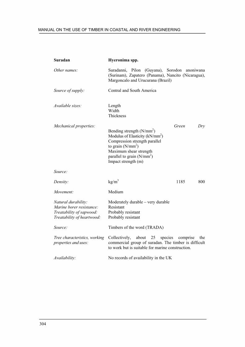
MANUAL ON THE USE OF TIMBER IN COASTAL AND RIVER ENGINEERING
304
Suradan Hyeronima spp.
Other names: Suradanni, Pilon (Guyana), Sorodon anoniwana(Surinam), Zapatero (Panama), Nancito (Nicaragua),Margoncalo and Urucurana (Brazil)
Source of supply: Central and South America
Available sizes: LengthWidthThickness
Mechanical properties: Green DryBending strength (N/mm2)Modulus of Elasticity (kN/mm2)Compression strength parallelto grain (N/mm2)Maximum shear strengthparallel to grain (N/mm2)Impact strength (m)
Source:
Density: kg/m3 1185 800
Movement: Medium
Natural durability: Moderately durable – very durableMarine borer resistance: ResistantTreatability of sapwood: Probably resistantTreatability of heartwood: Probably resistant
Source: Timbers of the word (TRADA)
Tree characteristics, workingproperties and uses:
Collectively, about 25 species comprise thecommercial group of suradan. The timber is difficultto work but is suitable for marine construction.
Availability: No records of availability in the UK

APPENDIX 1
305
Tatajuba Bagassa guianensis
Other names: Bagasse (Guyana), Gele bagasse (Surinam)
Source of supply: Guyana, French Guiana, Brazil and Surinam
Available sizes: LengthWidthThickness
Mechanical properties: Green DryBending strength (N/mm2) 121Modulus of Elasticity (kN/mm2) 17.3Compression strength parallel 78to grain (N/mm2)Maximum shear strengthparallel to grain (N/mm2)Impact strength (m)
Source: The strength properties of timber (HMSO, 1983)
Density: kg/m3 1100 720-840
Movement: Medium
Natural durability: Very durableMarine borer resistance: Moderately resistantTreatability of sapwood: Probably resistantTreatability of heartwood: Probably resistant
Source: Timbers of the world (TRADA)
Tree characteristics, workingproperties and uses:
The tree reaches a height of 27-30 m and a diameter of0.6 m. The bole is cylindrical and 18-21 m high. Thetimber has been used for heavy construction, bothcivil and marine.
Availability: No information on availability in the UK

MANUAL ON THE USE OF TIMBER IN COASTAL AND RIVER ENGINEERING
306
Teak Tectona grandis
Other names: Sagwan, Teku, Teka, Kyun
Source of supply: Myannmar, India, Thailand and has been introducedas a plantation species in Malaysia, Indonesia,Philippines and Central America. The properties listedbelow only refer to native teak from natural forests.
Available sizes: LengthWidthThickness
Mechanical properties: Green DryBending strength (N/mm2) 84 106Modulus of Elasticity (kN/mm2) 8.8 10.0Compression strength parallel 42.8 60.4to grain (N/mm2)Maximum shear strengthparallel to grain (N/mm2)Impact strength (m)
Source: Handbook of hardwoods (HMSO, 1997) Figuresabove are for Myannmar teak
Density: kg/m3 817 610-690
Movement: Small
Natural durability: Very durableMarine borer resistance: Moderately resistantTreatability of sapwood: Probably resistantTreatability of heartwood: Extremely resistant
Source: Handbook of hardwoods (HMSO, 1997)
Tree characteristics, workingproperties and uses:
On favourable sites, the tree can reach a height of 39-45 m and a diameter of 1.5 m with a clear bole of 10-24 m. The timber has been used for a wide range ofpurposes ranging from shipbuilding and heavyconstruction.
Availability: Good

APPENDIX 1
307
Turpentine Syncarpia glomulifera
Other names: Red lustre, Lustre
Source of supply: Queensland and New South Wales
Available sizes: LengthWidthThickness
Mechanical properties: Green DryBending strength (N/mm2)Modulus of Elasticity (kN/mm2)Compression strength parallelto grain (N/mm2)Maximum shear strengthparallel to grain (N/mm2)Impact strength (m)
Source:
Density: kg/m3 817 610-690
Movement: Small
Natural durability: Very durableMarine borer resistance: ResistantTreatability of sapwood: Probably resistantTreatability of heartwood: Probably resistant
Source: Handbook of hardwoods (HMSO, 1997)
Tree characteristics, workingproperties and uses:
Turpentine is a hard, dense timber, ideal for use in themarine environment.
Availability: No records of availability in the UK

MANUAL ON THE USE OF TIMBER IN COASTAL AND RIVER ENGINEERING
308
Uchi Sacoglottis guiansis
Other names: Bagasse (Guyana), Gele bagasse (Surinam)
Source of supply: Guyana, French Guiana, Brazil and Surinam
Available sizes: LengthWidthThickness
Mechanical properties: Green DryBending strength (N/mm2)Modulus of Elasticity (kN/mm2) 20.5Compression strength parallelto grain (N/mm2)Maximum shear strengthparallel to grain (N/mm2)Impact strength (m)
Source: Ecotimber handbook
Density: kg/m3 1100-1200 960
Movement: Large
Natural durability: Moderately durableMarine borer resistance: Probably not resistantTreatability of sapwood: Probably resistantTreatability of heartwood: Probably resistant
Source: Ecotimber handbook
Tree characteristics, workingproperties and uses:
Little information available
Availability: Available

APPENDIX 1
309
Utile Entandrophragma utile
Other names: Sipo (Cote d’Ivoire), Assie (Cameroon)
Source of supply: West and Central Africa
Available sizes: LengthWidthThickness
Mechanical properties: Green DryBending strength (N/mm2) 79 103Modulus of Elasticity (kN/mm2) 9 600 10 800Compression strength parallel 38.2 60.4to grain (N/mm2)Maximum shear strength 10.8 16.9parallel to grain (N/mm2)Impact strength (m) 0.74 0.74
Source: The strength properties of timber (HMSO, 1983)
Density: kg/m3 660
Movement: Medium
Natural durability: Moderately durableMarine borer resistance: Probably not resistantTreatability of sapwood: Probably resistantTreatability of heartwood: Probably resistant
Source: Handbook of hardwoods (HMSO, 1997)
Tree characteristics, workingproperties and uses:
Excellent general-purpose construction timber.Strength properties are similar to those of Americanmahogany. The tree reaches a height of 45 m and adiameter of 2.0 m. The bole is straight, free frombuttresses and can reach a height of 24 m.
Availability: Readily available

MANUAL ON THE USE OF TIMBER IN COASTAL AND RIVER ENGINEERING
310
Wacapou Soucapoua americanan
Other names: Bois angelim (French Guiana), Bruinhart of Wacapou(Surinam)
Source of supply: South America
Available sizes: LengthWidthThickness
Mechanical properties: Green DryBending strength (N/mm2)Modulus of Elasticity (kN/mm2)Compression strength parallelto grain (N/mm2)Maximum shear strengthparallel to grain (N/mm2)Impact strength (m)
Source:
Density: kg/m3 1200 945
Movement:
Natural durability: Very durableMarine borer resistance: Probably resistantTreatability of sapwood: Probably resistantTreatability of heartwood: Probably resistant
Source: Ecotimber handbook
Tree characteristics, workingproperties and uses:
The tree is tall, slender and not buttressed. The timberhas excellent strength properties and is superior tooak. It is relatively difficult to work.
Availability: No records of availability in the UK

APPENDIX 1
311
Wallaba Eperua falcata, Eperua grandifola
Other names: Waapa, Bijlhout, Apa, Ituri
Source of supply: Guyana, Surinam, Brazil
Available sizes: LengthWidthThickness
Mechanical properties: Green DryBending strength (N/mm2) 104 139Modulus of Elasticity (kN/mm2) 15.0 14.7Compression strength parallel 57.8 77.3to grain (N/mm2)Maximum shear strengthparallel to grain (N/mm2)Impact strength (m)
Source: Handbook of hardwoods (HMSO, 1997)
Density: kg/m3 910
Movement:
Natural durability: Very durableMarine borer resistance: Not resistantTreatability of sapwood: Probably resistantTreatability of heartwood: Extremely resistant
Source: Timbers of the world (TRADA)
Tree characteristics, workingproperties and uses:
The tree grows to about 30 m with a diameter of0.6 m. The timber is very hard and heavy, and gumexudation can be a problem when sawing or onfinished surfaces. It is used for wharf and bridgeconstruction, decking and flooring.
Availability: Available

MANUAL ON THE USE OF TIMBER IN COASTAL AND RIVER ENGINEERING
312
Zebrawood Astronium graveolens
Other names: Palo de cera, Palo de culebra, Gusanero, Gateodo,Guarita
Source of supply: Brazil, Colombia, Venezuela, Central America
Available sizes: LengthWidthThickness
Mechanical properties: Green DryBending strength (N/mm2) 133Modulus of Elasticity (kN/mm2) 17.1Compression strength parallel 76to grain (N/mm2)Maximum shear strengthparallel to grain (N/mm2)Impact strength (m)
Source: Ecotimber handbook
Density: kg/m3 1100 880
Movement: Large
Natural durability: Very durableMarine borer resistance: Probably resistantTreatability of sapwood: Probably resistantTreatability of heartwood: Probably resistant
Source: Timbers of the world (TRADA)
Tree characteristics, workingproperties and uses:
The tree can reach a height of up to 50 m with a boleof 20-30 m and diameter of 1.5 m. Bole is generallyclear and cylindrical.
Availability: No information on availability in the UK

313
Appendix 2.Model specification
TIMBER STRUCTURES – A FRAMEWORK FOR A CONSTRUCTIONSPECIFICATION
2.1 Preamble
The aim of this specification is to provide a framework for the constructionspecification of any timber structure used in coastal, harbour or river engineering bythe use of a simple iterative process aided by typical and site-specific drawings, andto provide in electronic form a template for the first draft of a Project Specification.The template in its complete and detailed form does not necessarily apply to everysituation, but it does provide a reasonably comprehensive list of the details that needto be addressed. To this end, the language used is as it would be in the finishedSpecification. Designers wishing to use this document as an aide memoir may do soby substituting the word ‘should’ for ‘shall’ wherever it occurs. For convenience theSpecification contains reference to outline details given elsewhere in this documentfor some frequently used elements.
Information contained in either standard or contract drawings should be referredto in the Specification. References should be in the form of “as Drawing Number …Detail(s)…” not by general reference. Words or phrases in [ ] are suggestions forlikely options, ( ) where contract specific detail needs inserting, …where referencesor numbers need inserting.
Final checks before issue of documentsCross check that the references to drawings in the Specification agree with thenumbering in the final version Issue Drawings.
Check that the names used for structures and members agree with those used inthe Bills of Quantity and the Issue Drawings.
The Specification follows a typical construction sequence, starting with thematerial supply and the Site Compound, and ending in Site Specials. After Section2.2, each type of main structure should have a separate heading, and the members ofeach structure should be dealt with in the overall order of sections, e.g. groynesshould contain specifications for piles, walings and planking. Raking supports togroynes should be a subsection to groynes: plant bays, end details and tie-ins shouldbe included under Site Specials.
Construction Constraints. These should be summarised within the ConstructionSpecification. The Constraints fall into two categories, General, which affect all ormost operations, and Specific, which affect one structure or class of structures. Theformer should appear as a preamble, the latter in the section(s) they affect. Thereshould be no need to reiterate the constraints in full – just a subject heading and a

MANUAL ON THE USE OF TIMBER IN COASTAL AND RIVER ENGINEERING
314
reference is adequate (i.e. Routing constraints as Dwg …, Noise constraints asEnvironmental Statement Clause …, Working hours as Spec. Clause…) – unless theyare only referred to generally elsewhere and full details are laid out in this section.The latter is most likely to apply to Specific Constraints. The aims of summarisingall the Constraints in one part of the document are to:
Give the design team a chance to check the following:i) All necessary constraints have been includedii) Constraints are not contradictoryiii) Superfluous constraints have not been included.Any of the above can have an adverse affect on costs, by decreasing buildability,or requiring post tender changes to construction methods.Give the tendering contractors’ teams a ready point of reference to start planningtheir methods of working, resourcing them, and preparing submissiondocuments.Provide an early reference point for site staff to help the contract to proceedefficiently.
Meanings:a) Engineer shall mean the person appointed to oversee the Contract on the Client’s
behalf.b) “….mm x ….mm” indicates the section dimensions, and may be substituted by
“Nominal ….mm x ….mm”, “[nominal] ….mm diameter [tapered (minimumdimensions or diameters)]”.
c) “….mm - ….mm long” is the length dimension. If all the members beingdescribed are the same length, then “….mm long” is appropriate.
d) References to Figures and Sections are to Figures and Sections incorporated inthe Manual unless otherwise indicated.
Abbreviations:Std. StandardDwg. DrawingNo. Number
2.2 Materials
Materials for works may be procured directly by the Client or included within theconstruction contract. Whilst the requirements for different types of structures willvary greatly, the following clauses will be applicable to most structures (although notrecycled components).
GeneralAll timber shall be of appropriate quality for use in marine and civil engineeringconstruction with ends cut square and appropriately protected. All timber shall befree from [sapwood] [shakes] [knots] [unsound or rotten heart] [holes or pluggeddefects] (other defects).

APPENDIX 2
315
Timber shall, where possible, comply with appropriate British Standards (e.g.BS 5756: 1997 Visual strength grading of hardwood) and be marked accordingly.Where applicable timber shall comply with [a recognised standard appropriate for thespecies and size of timber supplied] (e.g. Guyana Grading Rules for Sawn and BaulkTimbers). Copies of such standards shall be supplied to the Engineer.
Physical requirementsIt is essential that the required properties are clearly specified, in some situations thismay be through the specification of a particular species of timber from a particularsource. However, it is preferable to specify the generic properties required for eachparticular component and allow potential suppliers to provide costs for a range ofspecies fulfilling the requirements. In order to satisfy requirements for responsibleprocurement it will be necessary for the source and type of timber to be approved bythe Engineer before procurement proceeds.
It is suggested that physical requirements for each component are brieflydescribed and that the minimum requirements for each component are summarised ina table of the form shown below. This could be combined with Table 5.3 to provide acomprehensive summary of timber properties at the time of tendering.
Component Strength class Minimum density AbrasionResistanceto marine
borersDecay
1.2.3.4.
Dimensional toleranceTimber shall comply with BS EN 1313 –2. Permitted deviations and preferred sizesexcept where specified below:
Primary members
Secondary members
Tertiary members(Different tolerances are likely to be needed for hewn, sawn, thicknessed and
planed timbers in various size ranges)
Metal fixings and platesAll steel bolts, nuts, washers, coach screws, plates and fittings [excluding drivingrings] not made from stainless steel shall be hot-dipped galvanised in accordance withBS EN ISO 1461.

MANUAL ON THE USE OF TIMBER IN COASTAL AND RIVER ENGINEERING
316
2.3. Site Compound
a) Part of the Site Compound shall be designated as a Timber Compound forstorage and preparation of timber [as shown on layout Dwg. No….]. It shall beclearly demarked from the rest of the Compound.
b) All incoming timber shall be inspected for transit damage and conformity to theMaterials Specification before acceptance.
c) Timber shall be handled in such a way as to prevent bruising, warping orcracking.
d) Timber shall be stacked by type and section on bearers placed to preventdistortion during storage, and steps taken to protect it from weather wherenecessary. Stacks should be limited in height bearing in mind current Health andSafety legislation, risks to operatives and trespassers (especially juveniles), firerisk (especially with small section softwood) and possible warping or otherdamage to the timber.
e) Everyone working with timber shall have suitable personal protection (seeHealth & Safety legislation). Where there is a legal requirement for machineryoperators to be certified, regular checks shall be made to ensure that all relevantcertificates are held and are up to date.
f) For ease of operation and convenience the following preparatory works normallytake place in the Compound:i) Cutting to length where appropriate.ii) Preparation of piles [including fitting shoes and rings as shown in Figure
7.11].iii) Where practicable, drilling bolt and dowel holes. Bolt holes shall generally
be larger than the nominal bolt diameter [see Specification clause/DrawingNumber] [recessed for bolt heads, nuts and washers]. Bolts shall betightened so that members fit closely and retightened when timbers reachstable moisture content. Dowel holes shall be drilled not greater than thenominal dowel diameter. Bolt and dowel holes shall be drilled completefrom one side. See Section 6.6.4
iv) Where practicable, drill pilot holes for screws, spikes and dogs. Holes forcoach screws shall be drilled as [Figure 6.15] [and recessed for heads andwashers]. See Section 6.6.4. Smaller screws (such as deck battenfastenings) and square fittings shall be predrilled as [Dwg….].
g) Cut ends of all treated timber to be coated with a suitable (specify) sitetreatment.
h) Prepared timber shall be stacked separately to unprepared timber.i) Where possible all offcuts shall be used in the Contract. At the end of the
Contract the Engineer shall inspect the remaining offcuts, selecting any suitablefor salvage to be disposed of in accordance with the Contract [Clause number…](or detail arrangements). The balance shall remain the property of theContractor. [Burning on site will not be permitted.]
j) Where cutting and/or drilling is required in places where there is a risk ofequipment coming into contact with water or wet ground, such as the intertidalzone, over water or water margins, it is good and safe practice to limit equipmentto non electric tools such as hand, hydraulic or air powered tools.

APPENDIX 2
317
2.4. Demolition
a) Demolition shall be carried out in such a way as to maximise materials for re-cycling unless otherwise ordered by the Engineer. [In particular ….]
b) Salvaged timber shall be taken to the Timber Compound for inspection,machining and approval for reuse.
c) Reusable timber shall be stacked as for new in stockpiles separate from newtimber.
d) At the end of the Contract the remaining reusable timber shall be disposed of [inaccordance with Clause…] (or detail arrangements).
e) Where there are problems carrying out demolition as in a), the Contractor shallconsult with the Engineer and the Engineer shall instruct the Contractor as tosteps to be taken [see Clause…]. {i.e. piles which won’t draw to be cut off atsubstrate/bed level, timbers buried in a disturbance sensitive substrate to be leftin situ.}
f) Demolition Constraints.
2.5. Primary members
Member categories are as described in Section 6.6.1 and illustrated in Figure 6.9.Primary members include those contributing to the main stability of the structure(such as piles, posts, ramp/stair supports and the like but generally not fence, railing,notice board or sign board posts, etc.)
a) Pilesi) Piles for (name of member) shall be ….mm x ….mm (type of timber)
….mm - ….mm long and driven to the depths/set/cap levels shown onDwg(s). No….
ii) Piling shall be carried out generally in accordance with Specification forPiling Works and Embedded Retaining Walls as published by the Institutionof Civil Engineers insofar as it relates to timber piles, with the addition thatfaces of piles to receive further fixings shall be aligned to within [1 in 25](or state other tolerance) of the line shown on the drawings.
iii) The Contractor shall obtain approval of the proposed piling methods beforecommencing work.
iv) The Contractor shall probe for obstructions [at each pile position] [as shownon Dwg. No….] [as directed by the Engineer] [as scheduled ( )]
v) Obstructions shall be dealt with as instructed by the Engineer.vi) Unseated piles shall be re-driven.vii) Where there are indications of difficult driving conditions (data to be
provided by the Client), the Contractor shall submit proposals for jetting in,pre-boring or phased driving with the piling proposals.
viii) All pile heads shall be cleaned of burrs, splinters or ragged projections afterdriving [and damaged rings replaced with new, secured by nails ifnecessary]
ix) Pile extensions shall be formed by cutting off the existing pile square andfixing a ….mm x ….mm (type of timber) extension piece ….mm - …mm

MANUAL ON THE USE OF TIMBER IN COASTAL AND RIVER ENGINEERING
318
long [complete with pile cap] jointed as Std. Dwg…. [and driven as formain piling] see Dwg. No…. for details
b) Posts shall be ….mm x….mm (type of timber) ….mm x ….mm long fitted intosockets/post holes/built into ( )] as Dwg. No….
c) Supports shall be ….mm x ….mm (type of timber) …mm - ….mm long as Dwg.No…. Detail(s)….
d) Plank piles shall be ….mm x ….mm (type of timber) ….mm long. Piles shall bedriven [vertically] [perpendicular to the [bottom] [waling] [shaped] and fixed tothe [bottom] waling as Dwg. No…. A margin of [150 mm] (or state other) isallowed above the top of the waling to accommodate the driving head. [Piles ineach panel shall be driven ‘up-slope’]. After driving all piles shall be cut offlevel with the top of the waling and any splinters or rough edges removed (or asspecified, taking into consideration Health and Safety and Public Safetyconsiderations).
e) Primary Member Constraints.
2.6. Secondary members
Secondary members provide the main distribution of loads within the structure andare usually fixed by bolting. They include transoms, walings, pier/dolphin/jettystruts, fenders, capping beams, rubbing strakes, kerbs (for vehicle carrying decks) andthe like.
a) (Name of member) ….mm x ….mm (type of timber) [shaped as Dwg. No….]fixed [at ends to (name of receiving member)] [at ….mm centres to (name ofmember or receiving surface) by (description of fixings) all as Dwg(s). No(s)….Detail(s) [and jointed as Std. Dwg. No….] [at (preferred joint position(s)].
b) Secondary Member Constraints.
2.7. Tertiary members
Tertiary members are generally less substantial timbers, providing cladding andfunctionality. Examples include groyne planks, deck battens, ramp surfaces, fasciasand the like, usually fixed by screws, spikes or dogs.
a) (Name of member) ….mm x ….mm (type of timber) fixed to [member(s)] with(description of fixings), joints as Std. Dwg. No…. at (description of joint layout)all as Dwg. No…. [Surface treatment (specify)].
b) Tertiary Member Constraints.
2.8. Other timbers
This section covers timbers which are not predominantly driven, bolted, screwed,spiked or dogged. It includes timber slotted into steelwork, concrete or other timber

APPENDIX 2
319
and any security fixing i.e. top planks of flood boards, digging in or bolting of bottomplanks slotted between king-posts/piles. It also covers unfixed timber (fascines), tied(willow wipes), ground beams, gravity cribwork and earth bank reinforcement.
a) (Name of member) [….mm x ….mm)] [….mm diameter] (type of timber)[….mm long] [slotted into] [laid on] [tied to] [buried in] (description ofmember/surface) [and secured by (description)] joints as Std. Dwg. No…. [(jointpattern)] as Dwg. No….
b) Other Timber Constraints.
2.9 Site specials
This section is to contain the variations on the main structures such as end, change ofdirection, and tie-in details, box-outs, plant bays and the like. It should also containany architectural embellishments, items likely to be constructed or prefabricated offsite, accommodation works, handrails, gates and fencing where they arepredominately timber construction. If for some reason one of these elements – say,fencing – becomes a major element of the Contract, it should be listed as a mainstructure and specified accordingly. Some possibilities are listed below
a) Plant bay …. planks high as Dwg, No…. [in Groyne(s) No….] [as LayoutDwg(s). No….]
b) (Name of structure) tie-in to (name of structure) as Dwg. No….c) (Name of structure) [end] [change of direction] [box-out] detail as Dwg. No….
[as (list of sites)] [as Dwg(s). No….]d) (Architectural detail) [fixed] to (structure and member) [by (type of fixing)] as
Dwg. No….e) Notice/sign board fixed to [supports bedded in] [structure/surface] by (type of
fixing) as Dwg. No…. located [(description of site(s)] [as shown on Dwg. No….f) Walkway deck in (type of timber) ….mm x mm [with non-slip surface
(describe)] fitted to pontoon as Dwg. No….g) Steps consisting of….mm x….mm (type of timber) stringers ….mm - ….mm
long with …mm x….mm treads (type of timber) [and with non-slip finish(describe)] fixed between (head and toe members) [in (name of structure)] asshown in Dwg. No…. Detail(s)…. [at (list of sites)] [as shown in LayoutDwg(s). No….]
h) Handrailing consisting of ….mm x ….mm posts in (type of timber) [fixed to(structure and member)] [embedded in] [at ….mm centres] with (type of timber)[top] railing(s) [shaped as Dwg. No…. Detail…] [and (number) of intermediaterailings in ….mm x ….mm (type of timber) at ….centres] [fitted with ….mmx….mm toe board in (type of timber) all as shown in Dwg. No…. Details….
i) Site Specials Constraints.
Note: - The Dtp. Specification for Highway Works contains Specifications for mostof the more commonly used types of timber/timber composite fences and gates. Ifsomething different is needed, then follow subsection h) above.

MANUAL ON THE USE OF TIMBER IN COASTAL AND RIVER ENGINEERING
320
Useful Outline Drawings
Planted Post Fig. 6.3Plank Piles Fig. 6.4Buried Panels Fig. 6.5Props/Struts Fig. 6.6Groyne Ties Fig. 6.7Overlap Joint Fig. 6.10Butt Joint Fig. 6.11Scarf Joint Fig. 6.12Notched Joint Fig. 6.13Double Shear Joint Fig. 6.14Coach Screw Fixing Fig. 6.15Plate Connection Fig. 6.16Steel Angle Connection Fig. 6.17

321
Index
abiurana 237abrasion 40–1, 104, 117, 162, 209acaria quara 238access steps 183–5accidental damage 114accreditation 88‘actions’, limit state design 116adaptability of groynes 162–4Afzelia spp. 239air tools 149Albizia ferruginea 240alkaloids 47amiemfo-samina 240analyses 7–10, 12–13, 59, 93–4, 103anchored piles 201–2ancillaries 123–5Andaman padauk 241Andira spp. 242Androstachys johnsonii 286angelim vermelho 243anoxic conditions 196appraisal process 134–6, 138Artocarpus spp. 274Arun District Council 218–19Aspidosperma spp. 294, 299assessments 211–13degradation 207–11environmental impacts 134species identification 213–14timber structures 207–14Astronium spp. 288, 312ayan 244
Bagassa guianensis 305Balanocarpus heimii 251balau 245bank protection 195–9basralocus 246baulks 23–5, 131bed protection 195–9belian 247bending strength 39–40Biocidal Products Directive 61biological attacks 41–7, 97–100, 207–9boardwalks 137boat slipways 183–5bolts 121, 145, 161
bompagya 248boron-based preservatives 143Bournemouth 13–14, 144–5, 217–18boxed heart 23–4, 64–5Brachylaena lutchinsii 290breastworks 168–73British Standards (BS) 53–5, 57–8, 66British Waterways 188, 190–1British Wood Preserving and Damp-
proofing Association (BWPDA)53–5
Bruguiera gymnorrhiza 249brush box 250brushwood protection 164–7, 198BS see British Standardsbulkheads 168–9buried panels 109–10butt connections 118, 144–5BWPDA see British Wood Preserving and
Damp-proofing Association
cantilever piles 201–2capping piles 143carbon neutrality 6, 76Caryocar villosum 293case studies 180–1, 203–5CCA see chromated/copper/arsenate
preservativesCDM see Construction (Design and
Management) Regulationscedars 284cell types
hardwoods 20–1softwoods 18–19
cellulose 15certification 84–90, 147chain of custody 79, 85chainsaws 150‘checks’ (cracking) 178chemicals
degradation 209–10risks 149
chengal 251chromated/copper/arsenate (CCA)
preservatives 49–50, 57–8, 59–60,61–2
cladding 200–6

MANUAL ON THE USE OF TIMBER IN COASTAL AND RIVER ENGINEERING
322
Claricia racemosa 265classification systems 18–21, 44–5, 55–61coach screws 121–2, 144, 161coal-tar preservatives 51, 57–8, 62coastal environments 132, 156–7
see also marine environmentscodes of practice 95–6Combretodendron africanum 39–40, 256,
261commercial availability 26–7composites 65–71concrete 11, 153conditions
human activity 104–5see also operating conditions
configurationsaccess steps 184–5bed and bank protection 197–9breastworks 169dune fences 167earth retaining structures 201flap gates 194groynes 157–64lock gates 189outfall supports 182structure 107wave screens 173–4
connections 117–20design process 112, 125–6durability 144–5earth retaining structures 202flap gates 194groynes 160–1lock gates 190–2mooring dolphins 187selecting type 120wave screens 174
construction 129–54details 94environmental appraisal outcome138facilities 127groynes 157, 164human activity impact 104–5maintenance 151–2marine borer attacks 100potential hazards 131–2risks 148–9safety 130–1specification framework 313–20techniques 150–1tools 149–50
Construction (Design and Management)Regulations (CDM) 129–30
conventional structures 158, 169–71conversion of timber 23–7copper fixings 145–6Cordia goeldiana 263core samples 212–13corrosion products 145–6costs
design process 93dune protection 166groynes 9, 159–60repairs and maintenance 219whole life costs 7–8, 93
Cotylelobium spp. 301courbaril 252cracking 178creosote-based preservatives 51, 57–8, 62crevice corrosion 145–6cribwork 197criteria, forestry bodies 87–8, 90critical values (CVs) 59–60cross-flow forces 101–2cross sections
earth retaining structures 204member design 115wood structure 16–18
crustaceans 42–3, 46–7, 98–9, 144cumaru 39, 253cupiuba 254current action 101–2CVs see critical valuesCylicodiscus gabunensis 257
dahoma 255danta 39–40, 256decay detection drilling 212decay process 138–9, 141–3
see also fungal decaydecision tree, preservative use 52–3decking 68, 175–81defect examinations 94deforestation see forest lossdegradation 73–6, 145–6, 207–11demolition 317density factors 40, 47denya 257Deptford Creek, London 203–5designers’ responsibilities 129–30design process 93–128, 129–54
connections 112, 125–6decking 177–8

INDEX
323
durability by design 138–45environmental issues 136–8maintenance considerations 215–16members 112–17pile design 153references 95–6risk assessments 130
determa 258Dialum spp. 276Dicoryia guianensis 246diffuse porous timbers 20dimensional tolerances 315dingy ramps 185Dinizia excelsa 298Dipterix spp. 39, 253Dipterocarpus spp. 277Distemonanthus benthamianus 244distortion 33–4documents 80–1, 313–14dolphins for mooring 185–7double shear connections 120Douglas fir 259dowels 122–3drag forces 101–2drainage 139, 141drilling, decay detection 212drip detail 141–2driving piles 153–4dry grade stresses 37drying process 32Drylobalanops spp. 271dry rot fungi 208dunes 137, 164–73durability 40–7, 138–46
bed and bank protection 196by design 138–45connections 145decking design 177extractives’ role 16fastenings 145groynes 144–5hazard classes 106–7ratings 44–5
duration of loading 115Dutch minimum requirements 77–8, 79–
80
earlywood zone 16, 18–19earth retaining structures 200–6Eastbourne groynes 5–6, 133East Sussex 5–6, 133, 169–70economic factors 55, 76, 156
Ecopoints estimator 8, 9, 11effective cross sections 115ekki 45, 183, 260elm 104empty cell treatment 49end distances 125end grain protection 141–2end of structure lifetime 219engineering issues
life cycle analysis 8–9timber structures 12–14
enhancement of structures 215–20Entandrophragma utile 309Enterolobium schoenburgkii 262environmental issues 6, 134–8
appraisals 134–8consequences of timber use 73–6, 79FSC principles 90groynes 9, 156life cycle analysis 8preservation 61–2procurement of timber 78–9
Eperua falcata 311Escweilera spp. 283essia 261EU see European UnionEucalyptus diversicolor 272Eucalyptus globulus 303Eucalyptus marginata 270European Union (EU) legislation 61–2, 75Eusideroxylon zwageri 247examination of structures 94–5ex-stock timber 91extractives 16, 17–18
faggots 198fascines 197fasteners 120–3, 145favinha 262fencing 164–7, 174fender piles 185–7, 190fibre saturation point 32–3fibres in hardwood 20finishes 126–7
decking 178–9earth retaining structures 205flap gates 194groynes 161mooring dolphins 187
fire degradation 210–11fir properties 259fittings 126–7, 161, 178–9, 187, 194

MANUAL ON THE USE OF TIMBER IN COASTAL AND RIVER ENGINEERING
324
fixings 120–3corrosion 145–6decking 178–9, 181durability 145earth retaining structures 205groynes 161maintenance 152specifications 315
flap gates 192–5forest loss 73–6forest management 6, 76–80, 84–6, 90forestry standards 87–8Forestry Stewardship Council (FSC) 89–
90forward shipments 91foundations 152–4freijo 263fresh water environments 61, 70–1, 97–8
see also river environmentsFSC see Forestry Stewardship Councilfull cell treatment 49–50functional requirements 96–105fungal decay 41–2
degradation 207–9durability classes 107fresh water 97–8moisture content 138, 141–3monitoring and assessment 213
G8 Action Programme on Forests 75gabions 198geometry of groynes 159–60global impact, forest loss 74glued connections 123glulam (glued laminated timber) 66–8, 69,
70Goupia glabra 254, 278government agreements/policies 77–8government guidance 79–80grading
timber strength 35–40wet/dry grade stresses 37
greenheart 20–1, 24, 39–40, 142, 264gribble 42–3, 46–7, 98–9, 144gross features of wood 16ground conditions 97groynes 155–64
alternative materials 10–11construction work 133durability 144–5Eastbourne 5–6environmental design 137
fixings 161geometry 159-60literature 164outfall support configuration 182piles 159–60, 162–3properties 5repairs and maintenance 217–19rock/timber comparison 9rolling reconstruction 12–14spliced piles 125stability 109–12tie-fitting 151wave action 103
guariuba 265guidance 79–80, 155–206
habitat provisions 204–6hammer soundings 212handling timber 146–7, 149hand tools 150hardness of timber 41, 47hardwoods 18, 20–1
commercial availability 26–7environmental damage 73groyne timbers 157procurement 78readily available species 29species properties 28–31strength-grading 36–7, 38–40tolerances 26–7vessels 20-1
hazard classes 48–9, 51, 65, 106–7hazards of construction 131–2health and safety 129–34heartwood 17–18
boxing 23–4, 64–5natural durability 44plan view 142suitability for water use 60–1
hemicellulose 15Heritiera littoralis 266hewn timber 24, 27high pressure treatment 48–50horizontal surfaces 139–40human activity impact 104–5, 146–7hurdles 199hydrostatic loading 101Hyeronima spp. 304Hymeneae spp. 252Hymenolobium spp. 243
identification of species 213–14

INDEX
325
illegal logging 75–6impermeable groynes 158importation 27incising treatments 56–7indicators, forestry standards 87indigenous peoples 90industrial timber preservation 48, 60
see also preservation...insect attacks 41–2, 97, 209inspections 147, 211–13, 218–19international agreements 77ipê 267itauba 268
jarana 269jarrah 270jetties 175–81joints, dowels 123
kapur 271karri 272kauta 273keledang 274kempas 275keranji 276keruing 277king piles 203–4Koompassia malaccensis 275kopie 278
labelling 85–7laboratory trials 46–7laminated strand lumber (LSL) 69laminated timber 66–71laminated veneer lumber (LVL) 69, 70–1larch 279Larix spp. 279latewood zone 16–17, 18–19Lecythis spp. 269legalities
definition 79, 81–2environmental appraisals 135procurement schedule 91–2verification 84
legislation 61–2, 75Licania spp. 273life cycle analysis 7–10, 12–13life expired structures 219light organic solvent preservatives
(LOSPs) 51lignin 15limit state design 115–16
Limnoria spp. 42–3, 46–7, 98–9, 144live stabilisation 197living forests 6–7, 76loadings
assessments 96–7connection design 125–6current action 101human activity 104–5member design 114–16sharing systems 115stability of structures 112water levels 101wave action 102–3wind 103–4
local impactsexisting structures 95forest loss 74
lock gates 188–95logging illegally 75–6log ties 111London 203–5Lophira alata 45, 183, 260LOSPs see light organic solvent
preservativeslouro gamela 280louro itauba 281louro preto 282low cost structures 159–60, 172low pressure treatment 51–2LSL see laminated strand lumberLVL see laminated veneer lumberLymington flap gates 192–4
machine strength-grading 35machining timber 63–4, 82, 127maintenance 151–2, 215–20
bed and bank protection 199costs of design 93decking 179dune protection 167–8earth retaining structures 206flap gates 195groynes 162revetments 173
Mammea africana 248manbarklak 283mangrove cedars 284Manilkara spp. 285manual, guide to using 1–3marine borers 42–4, 98–100
degradation 209monitoring and assessment 213
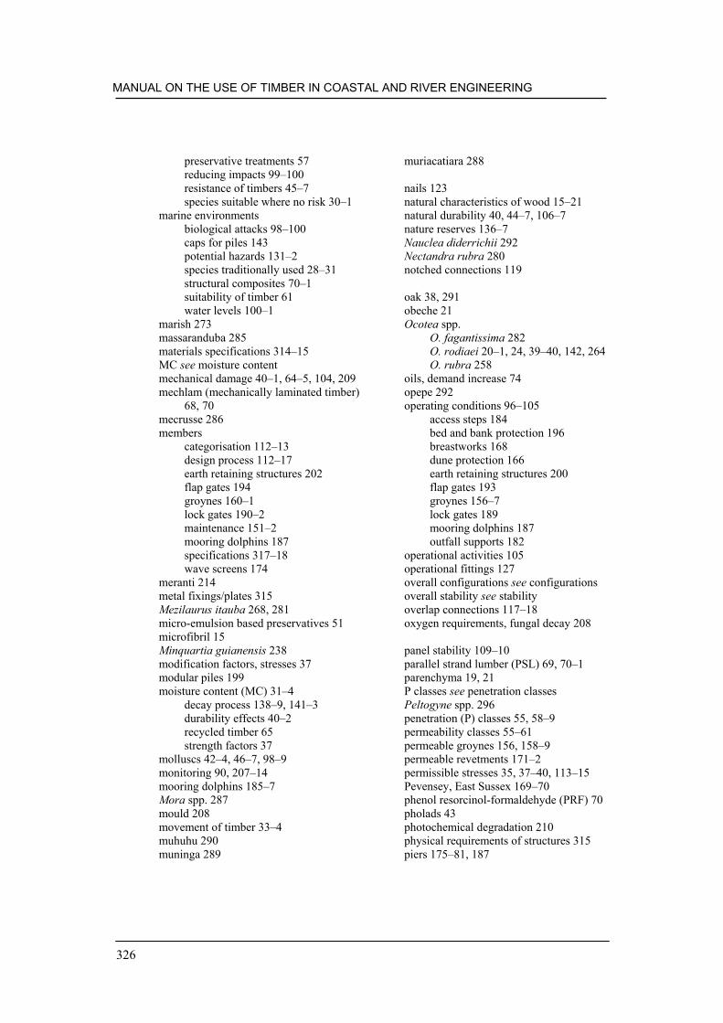
MANUAL ON THE USE OF TIMBER IN COASTAL AND RIVER ENGINEERING
326
preservative treatments 57reducing impacts 99–100resistance of timbers 45–7species suitable where no risk 30–1
marine environmentsbiological attacks 98–100caps for piles 143potential hazards 131–2species traditionally used 28–31structural composites 70–1suitability of timber 61water levels 100–1
marish 273massaranduba 285materials specifications 314–15MC see moisture contentmechanical damage 40–1, 64–5, 104, 209mechlam (mechanically laminated timber)
68, 70mecrusse 286members
categorisation 112–13design process 112–17earth retaining structures 202flap gates 194groynes 160–1lock gates 190–2maintenance 151–2mooring dolphins 187specifications 317–18wave screens 174
meranti 214metal fixings/plates 315Mezilaurus itauba 268, 281micro-emulsion based preservatives 51microfibril 15Minquartia guianensis 238modification factors, stresses 37modular piles 199moisture content (MC) 31–4
decay process 138–9, 141–3durability effects 40–2recycled timber 65strength factors 37
molluscs 42–4, 46–7, 98–9monitoring 90, 207–14mooring dolphins 185–7Mora spp. 287mould 208movement of timber 33–4muhuhu 290muninga 289
muriacatiara 288
nails 123natural characteristics of wood 15–21natural durability 40, 44–7, 106–7nature reserves 136–7Nauclea diderrichii 292Nectandra rubra 280notched connections 119
oak 38, 291obeche 21Ocotea spp.
O. fagantissima 282O. rodiaei 20–1, 24, 39–40, 142, 264O. rubra 258
oils, demand increase 74opepe 292operating conditions 96–105
access steps 184bed and bank protection 196breastworks 168dune protection 166earth retaining structures 200flap gates 193groynes 156–7lock gates 189mooring dolphins 187outfall supports 182
operational activities 105operational fittings 127overall configurations see configurationsoverall stability see stabilityoverlap connections 117–18oxygen requirements, fungal decay 208
panel stability 109–10parallel strand lumber (PSL) 69, 70–1parenchyma 19, 21P classes see penetration classesPeltogyne spp. 296penetration (P) classes 55, 58–9permeability classes 55–61permeable groynes 156, 158–9permeable revetments 171–2permissible stresses 35, 37–40, 113–15Pevensey, East Sussex 169–70phenol resorcinol-formaldehyde (PRF) 70pholads 43photochemical degradation 210physical requirements of structures 315piers 175–81, 187

INDEX
327
pile groups 111piles 152–4
advantages of timber 152ancillary devices 124–5bank protection 199capping detail 143current action 102design considerations 153driving procedure 153–4earth retaining 201–2, 203–4fender piles 185–7, 190greenheart plan view 142materials 10–11rubbing strips 218specifications 317–18stability 108–11see also groynes
pine 46, 214, 295, 300Piptadeniastrum africanum 255piquia 293piquia marfim 294pitch pine 295pith 23–4plain-sawn timber 25plank piles 109, 160planks 25–6
earth retaining structures 203–4groynes 160, 162, 217–19
plant 149–51plantations 73–4, 90planted posts 108–9plastics 11, 69–70plates 124, 315plugs, decking 178–9plywood-backed groynes 217–18policies, procurement 76–80pontoons 175–81pores see vesselsposts 108–9, 189, 201potential hazards of construction 131–2Pouteria guianensis 237preservation of timber 48–62preservatives
boron-based 143life expired structures 219marine borer attacks 99permeability of timber 55–61risks 149standards 53–5treatment methods 48–53, 55–61types 48–53
pressure intensity calculation 101pressure treatment 48–52, 55–6
prestressed decking plates 68PRF see phenol resorcinol-formaldehydeprimary members 112–13, 152, 317–18
see also pilesprinciples, forestry bodies 87–8, 90private sector timber use 79processed timber 23–72procurement 73–92
based on understanding 78–9framework 80–2issues 76–80policies 76–80risks 148–9schedule 91–2specifications 91–2timber species 235
props 110protection schemes 164–73, 195–9, 204–6
see also environmental issuesPseudotsuga menziesii 259PSL see parallel strand lumberPterocarpus spp. 241, 289public sector timber use 79purchase of timber 91–2purpleheart 184, 296pyinkado 297
quality control 35, 66, 88, 148quantities of timber 149quarter-sawn timber 25–6quasi-static analysis 103Quercus spp. 38, 291
radiused surfaces 139–40ray tissue structure 16reactive repairs 216readership of manual 1–2reclaimed timber 62–5recycled timber
definition 81groyne construction 11life expired structures 219procurement 84properties 62–5
red angelim 298red peroba 299redwood (European) 300regulations 129–30renewal costs 93repairs 215–20reporting procurement 91–2reprofiling groynes 163–4resak 301

MANUAL ON THE USE OF TIMBER IN COASTAL AND RIVER ENGINEERING
328
resin 18resistance to preservatives 56, 59responsible procurement of timber 73–92revetments 168–73ring porous timbers 20rings
pile-driving 153–4wood cross-section 16–17
risks 130, 148–9river environments
currents 101earth retaining structures 202groynes 157lock gates 188potential hazards 131–2species traditionally used 28–31water levels 100–1see also fresh water environments
Robinia pseudoacacia 302rock groynes 9rolling reconstruction programmes 12–14rubbing pieces 163, 185–6, 218
Sacoglottis guiansis 308safety factors 55, 130–1
see also health and safetySaltburn Pier refurbishment 180–1salt deposition 98sampling 212–13, 214sand dunes 137, 164–73sapstain fungi 208sapwood 17, 24, 195–6sawn timber 25–7scarf connections 118–19Scots pine 46scour 173screen protection 198screws 121–2, 144, 161sealing timber 100sea water see marine environmentssecondary members 112–13, 152, 318section sizes, members 115selection of timber 105–7, 146–7, 220seraya 214serviceability limit state 115–16service classes 114–15service factors 55service life 10, 71
see also life cycle analysisshear connections 120, 123sheeters 190shipping timber 91shipworm 42–4, 46–7, 98–9
shock loads 83shoes, pile-driving 153–4Shorea spp. 214, 245Shoreham, West Sussex 171, 185shrinkage 33, 177silica 47site compound 316site specials 319slings for timber 147slip, connections 126slipways 183–5sloping revetments 171–2sluices 192–5small clear specimen testing 34–5soft rot fungi 41, 42, 98, 208softwoods 18–19, 26–7, 36, 178Soucapoua americanan 310southern blue gum 303southern yellow pine 214spacing rules, connections 125–6species properties 28–31, 235–312
access steps 184bed and bank protection 196breastworks 169decking 176–7dune fences 166–7earth retaining structures 200flap gates 194groyne timbers 157identification 213–14lock gates 189movement values 34permissible stresses 37–40strength-grading 35–6, 37–40wave screens 173
specifications 91–2, 313–20spikes 123spliced piles 124–5, 154splintering propensities 83spray 103–4stability 195–9
earth retaining structures 202flap gates 194groyne structures 160outfall supports 183revetments 173structure 108–12wave screens 174
stake protection 199standards 53–5, 87–8
see also British Standards

INDEX
329
steelangles 124composites 68flat plates 124straps 124washers 123
steps for access 183–5stockpiling procedures 146stop logs 195strength 34–40
grading 35–40identification of species 213–14species properties 235–6structural composites 65, 67–8
stressesmember design 113–15modification factors 37pile design 153species properties 37–40testing 34–5
stress-grading see strength-gradingstress-laminating 68structural size testing 35structural timber composites 65–71structure of manual 2–3structures
construction specifications 313–20earth retaining 200–6engineering issues 12–14enhancements 215–20existing structures 94–5life cycle analysis 7–10, 12–13monitoring and assessment 207–14specific guidance 155–206wood 15–18
submerged screens 198support trestles 181–3suradan 304sustainability
definition 79, 81–2forest management 76–80, 84–6procurement schedule 91–2verification 84
swelling 33Syncarpia glomulifera 307
Tabebuia spp. 267tar-oil preservatives 51tatajuba 305teak 306technical requirements 82–3, 105–7Tectona grandis 306
temperate hardwoods 28–9, 157Teredo spp. 42–4, 46–7, 98–9tertiary members 112–13, 318tests
abrasion resistance 41marine borer resistance 46–7timber strength 34–5
thatching protection 164–7thermal degradation 210tidal currents 101ties 111, 151timber
availability 83case for using 76choice of structure 96comparing other materials 9, 11dogs 123identification of species 213–14in the round 57plates 124properties 5selection 105–7, 146–7, 220working with 133–4see also species properties
tissue structure of wood 16tolerances 26–7, 148, 153, 315tools 149–50, 212–13toxicity of timber 133–4tracheids 19transition wood 45transverse sections 20–1Tristania conferata 250tropical hardwoods
environmental damage 73groyne timbers 157procurement 78readily available species 29species properties 28–9strength-grading 36–7, 38
turpentine 307tyloses 18
uchi 308UK see United Kingdomultimate limit state 115–16United Kingdom (UK)
government policies 77marine borer survey 99
users of manual 1–2utile 309

MANUAL ON THE USE OF TIMBER IN COASTAL AND RIVER ENGINEERING
330
Vac-Vac® low pressure treatment process52
veneers 69ventilation 140–1verification 84–90vertical breastworks 171vessels, hardwoods 20–1Viaticum spp. 301visual strength-grading 35–6, 39
wacapou 310waling 190walkways 192wallaba 311wane 24washers 121, 123wastage 149water-borne preservatives 48–50water conditions/levels 97–101water content see moisture contentwave action 101–3wave barrier fencing 166–7, 174wave screens 173–5
wear and tear 95weathering 210West Sussex 171, 185wet grade stresses 37wet rot fungi 42, 209whole life costs 7–8, 93wind 103–4wood
classification 18–21natural characteristics 15–21structure 15–18see also timber
wood-plastic composites (WPCs) 69–70wood preservatives see preservativesWPCs see wood-plastic composites
Xylia xylocarpa. 297Xylocarpus granatum 284
zebrawood 312zigzag-shaped groynes 159–60