manual sunways solar inverter nt 10000nt 12000 english · solar modules which require earthing of...
TRANSCRIPT

User ManualSunways Solar Inverter
NT 10000, NT 11000, NT 12000
English EN

2 NT 10000...NT 12000

NT 10000...NT 12000 I

ImpressumAll rights reserved© Copyright by:Sunways AG Photovoltaic Technology Macairestraße 3 - 5 D-78467 Konstanz
Phone: +49 (0)7531 996 77-0
Fax: +49-(0)7531 996 77-444
EMail: [email protected]
Internet: www.sunways.de
This user manual may only be reprinted or copied in whole or in part with the express, written approval of Sun-ways AG. Any type of reproduction, distribution or storage on data carriers in any form and of any kind not au-thorised by Sunways AG represents a violation of the applicable copyright laws and will be prosecuted. Wereserve the right to make technical changes which serve to improve the unit, or which increase the safety stan-dard – even without separate prior notice.
Publisher responsible for the content: Sunways AG
This user manual contains products and product names which are registered trademarks. The mention of pro-ducts and product names is used only for information purposes and does not represent product misuse. The pas-sage referring to these products in this user manual does not represent original documentation of the respectiveproduct.

Introduction
Introduction
Thank you for purchasing an NT series Solar Inverter from Sunways, an innova-tive, high-quality product with unique features and consistently high efficiency.
This Solar Inverter is equipped with HERIC®topology and enables operationwith a large number of solar modules and – as accustomed from Sunways – wi-thout the use of a transformer.
This user manual contains instructions for using the Sunways Solar Inverter andexplains its functionality. Information is provided on safety, installation, com-missioning, operation and system monitoring.
Please follow the safety instructions carefully to ensure increased safety at theoperating site of the Solar Inverter.
NT 10000...NT 12000 III

Introduction
IV NT 10000...NT 12000

Introduction . . . . . . . . . . . . . . . . . . . . . . . . . . . . . . . . . . . . . . . . . . . . . . . . . . . III
1 Product description . . . . . . . . . . . . . . . . . . . . . . . . . . . . . . . . . . . . . . . . . . . . . 11.1 Intended use . . . . . . . . . . . . . . . . . . . . . . . . . . . . . . . . . . . . . . . . . . . . . . . . . . . . . . . 11.2 Functional description . . . . . . . . . . . . . . . . . . . . . . . . . . . . . . . . . . . . . . . . . . . . . . . . 11.3 Integration into solar system . . . . . . . . . . . . . . . . . . . . . . . . . . . . . . . . . . . . . . . . . . 21.4 Module description . . . . . . . . . . . . . . . . . . . . . . . . . . . . . . . . . . . . . . . . . . . . . . . . . . 41.5 Delivery Scope . . . . . . . . . . . . . . . . . . . . . . . . . . . . . . . . . . . . . . . . . . . . . . . . . . . . . . 4
2 Safety precautions . . . . . . . . . . . . . . . . . . . . . . . . . . . . . . . . . . . . . . . . . . . . . 72.1 General safety precautions . . . . . . . . . . . . . . . . . . . . . . . . . . . . . . . . . . . . . . . . . . . . 72.2 Explanation of symbols and warnings . . . . . . . . . . . . . . . . . . . . . . . . . . . . . . . . . . 82.3 Basic safety measures . . . . . . . . . . . . . . . . . . . . . . . . . . . . . . . . . . . . . . . . . . . . . . . . 92.4 Safety concept . . . . . . . . . . . . . . . . . . . . . . . . . . . . . . . . . . . . . . . . . . . . . . . . . . . . . . 9
3 Technical data . . . . . . . . . . . . . . . . . . . . . . . . . . . . . . . . . . . . . . . . . . . . . . . . 11
4 Installation . . . . . . . . . . . . . . . . . . . . . . . . . . . . . . . . . . . . . . . . . . . . . . . . . . . 134.1 Mechanical installation . . . . . . . . . . . . . . . . . . . . . . . . . . . . . . . . . . . . . . . . . . . . . . 134.2 Electrical installation . . . . . . . . . . . . . . . . . . . . . . . . . . . . . . . . . . . . . . . . . . . . . . . . 154.3 Installing the communication equipment . . . . . . . . . . . . . . . . . . . . . . . . . . . . . . . 22
5 Commissioning . . . . . . . . . . . . . . . . . . . . . . . . . . . . . . . . . . . . . . . . . . . . . . . 295.1 Connecting and disconnecting Solar Inverter . . . . . . . . . . . . . . . . . . . . . . . . . . . . 295.2 Commissioning. . . . . . . . . . . . . . . . . . . . . . . . . . . . . . . . . . . . . . . . . . . . . . . . . . . . . 29
6 Operation . . . . . . . . . . . . . . . . . . . . . . . . . . . . . . . . . . . . . . . . . . . . . . . . . . . 376.1 General information . . . . . . . . . . . . . . . . . . . . . . . . . . . . . . . . . . . . . . . . . . . . . . . . 376.2 System monitoring . . . . . . . . . . . . . . . . . . . . . . . . . . . . . . . . . . . . . . . . . . . . . . . . . 556.3 Sunways Browser . . . . . . . . . . . . . . . . . . . . . . . . . . . . . . . . . . . . . . . . . . . . . . . . . . 65
A Appendix . . . . . . . . . . . . . . . . . . . . . . . . . . . . . . . . . . . . . . . . . . . . . . . . . . . . 77A.1 Drilling template for the wall bracket . . . . . . . . . . . . . . . . . . . . . . . . . . . . . . . . . . . . . . . . . . 77A.2 General liability disclaimer . . . . . . . . . . . . . . . . . . . . . . . . . . . . . . . . . . . . . . . . . . . . . . . . . . . 77
V

VI

Product description
1 Product description
1.1 Intended use
The Sunways NT Solar Inverter is the link between your solar generator and thepublic power grid. The energy from the connected solar generator is convertedto grid-compliant AC current and fed into the grid.
Solar modules which require earthing of the negative or positive terminal can-not be operated with the NT Solar Inverter. If in doubt, always ask your modulemanufacturer about a release!
1.2 Functional description
Conversion from direct into al-ternating current
The NT Solar Inverter converts the direct current produced by the solar genera-tor into alternating current. The alternating current is then fed into the publicpower grid as a three-phase current.
Operating and display ele-ments
Various interfaces are available for system configuration and monitoring:
Control panel (LCD display and keyboard) for displaying operating and status values or for inputting system parameters
Operating LED
Integrated web server for display and configuration via a web browser
Interfaces Bus interface for connecting an analogue modem, ISDN modem or GSM/GPRS modem
Ethernet interface for connecting a PC or for integration in existing networks
CAN bus interface for interconnecting several Solar Inverters
S0 pulse output for controlling large displays
Alarm relay for realising simple monitoring locally
Interface for connecting an irradiance and temperature sensor
Data logging The NT Solar Inverter offers internal data logging for recording and saving sys-tem data:
5-minute mean values of voltages, currents, output, temperature and irradi-ance (if sensor is installed)
5-minute, daily, monthly and annual energy yield values
5-minute maximum and minimum values for AC output, irradiance, system output
Memory for malfunction messages
Grid monitoring The NT Solar Inverter assumes the task of grid monitoring for the protection ofthe unit and persons. In case of abnormal grid conditions, feeding is immedia-tely interrupted and the Solar Inverter disconnects from the grid by triggeringthe grid relay.
NT 10000...NT 12000 1

Product description
Functions resulting from the German Renewable Energy Act and the Medium- and Low-Vol-tage Directive
The Solar Inverter hardware already meets the requirements of the new Medi-um- and Low-Voltage Directive and will support all functions via software up-date by the end of the transitional period.
The output control through the PSC required according to the German Renewa-ble Energy Act can be realised via the optional CAN power control box.
Solar Inverter configuration The basic configuration of the NT Solar Inverter is shown in the block diagram.
The solar generator voltage connected to the inverter input is converted to al-ternating current by the high-efficiency HERIC® inverter. A 5-core AC connec-tion is used.
1.3 Integration into solar system
Solar generator configuration The technical data of the selected solar generator must match the Solar Inverterspecification (see Technical Data). Incorrect dimensioning can lead to reductionsin the yield and to destruction of the unit.
The Sundim design program from Sunways can be used for this purpose. Sun-ways Sundim can be found on the enclosed CD-ROM or on our website at http://www.sunways.eu/de/.
Be sure to take the following points into account before planning your system:
Watch the celestial alignment of the modules. In Central Europe a maximum yield is achieved with a module tilt of 30° to the horizontal and direct south orientation of the solar generator field.
=
~
L1
L2
L3
PE
N
L1 L2 L3 PE N
–
+ DC2+
DC2–
HERIC® inverter
Solar generator 2
Control and monitoring
Solar generator 1
Solar generator 3
+
+
–
–
DC1+
DC1–
DC3+
DC3–
Grid
2 NT 10000...NT 12000

Product description
The cell output decreases as the module temperature increases. Install your solar generator with sufficient ventilation at the rear.
Check your solar generator approx. every three years for soiling. This occurs especially on the lower edge of the modules and forms a haze that cannot be washed off even by heavy rain. Yield reduction can be prevented by cleaning the modules with a wet cloth or a brush.
Avoid shading of individual modules or solar cells in your system. This can lead to major reductions in yield.
Standard components of a so-lar system
Depending on the recommendations of your PV planning expert, your PV sys-tem consists of the following components:
1 Solar generator2 Solar Inverter with integrated DC
load break switch3 Mains fuse and energy meter
Options4 Irradiance sensor with integrated
temperature sensor5 PC for monitoring system6 large display
14
5
23
6
DC
AC
NT 10000...NT 12000 3
Product description
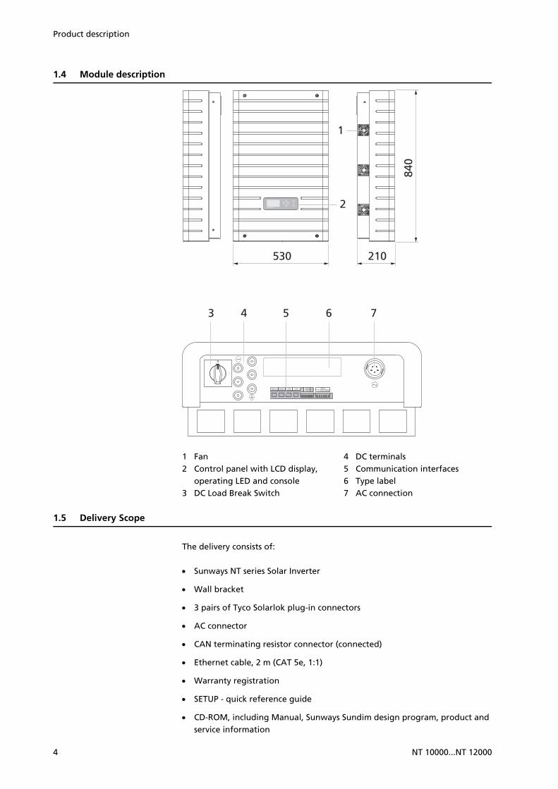
1.4 Module description
1 Fan2 Control panel with LCD display,
operating LED and console3 DC Load Break Switch
4 DC terminals5 Communication interfaces6 Type label7 AC connection
1.5 Delivery Scope
The delivery consists of:
Sunways NT series Solar Inverter
Wall bracket
3 pairs of Tyco Solarlok plug-in connectors
AC connector
CAN terminating resistor connector (connected)
Ethernet cable, 2 m (CAT 5e, 1:1)
Warranty registration
SETUP - quick reference guide
CD-ROM, including Manual, Sunways Sundim design program, product and service information
530
840
210
2
3 4 5 76
1
4 NT 10000...NT 12000

Product description
Checking delivery Before shipment our products are checked for proper condition. Despite care-ful, recyclable packing, transport damage may occur, for which the transportcompany is generally responsible.
Please check the delivered Solar Inverter thoroughly.
Should you discover damage to the packing or the Solar Inverter, please informthe transport company immediately. Your specialist dealer will be happy to pro-vide assistance if required. Any damage report must be received by the trans-port company in writing no later than seven days after receipt of the goods.
NT 10000...NT 12000 5

Product description
6 NT 10000...NT 12000

Safety precautions
2 Safety precautions
2.1 General safety precautions
Follow the instructions in the operating manual.
Safe handling and trouble-free operation of the NT Solar Inverter requiresknowledge of the basic safety precautions.
This user manual contains the most important information for operating thesystem safely.
Each person concerned with the installation, commissioning, maintenance andoperation of the Solar Inverter must have read and understood the entire usermanual, and in particular the chapter entitled Safety Precautions.
In addition, the rules and regulations for accident prevention applicable for theoperating site/plant must be observed.
Risks associated with handling the NT Solar Inverter
The Solar Inverter has been built in accordance with state-of-the-art technologyand the recognised safety rules and may only be used
for its intended purpose and
in safe condition.
Improper use may lead to dangers to the life and limb of the user or others, orcan adversely affect the system or other property.
In case of malfunctions which can impair safety, the system must be shut downimmediately and secured against being switched on again. The malfunctionmust then be eliminated immediately.
Warranty and liability The General Terms and Conditions of Sale and Delivery of Sunways AG alwaysapply. Warranty and liability claims for injuries and damage shall not be accep-ted if they are due to one or more of the following causes:
Improper use of the Solar Inverter
Improper installation, commissioning, operation and maintenance
Operation of the Solar Inverter with defective and/or non-operational safety and protective equipment
Failure to observe the information in the user manual regarding installation, commissioning, operation and maintenance
Unauthorised modifications
Inadequate monitoring of wearing parts
Improper repairs
Emergencies caused by external influence or force majeure
Opening the cover and removing the safety seal without prior permission from Sunways AG
NT 10000...NT 12000 7

Safety precautions
2.2 Explanation of symbols and warnings
The following warnings and symbols are used to help you quickly understandthis manual and safely use the Solar Inverter.
Warnings used in this user ma-nual
DANGERThis symbol indicates an immediate danger which will result in death, injury or serious damage if the applicable safety regulations are not followed.
DANGERDanger of death through electric shock! This symbol indicates an immediate danger from electric shock which will result in death, injury or serious damage if the applicable safety regulations are not followed.
CAUTIONCAUTION This symbol indicates an immediate danger which can result in damage if the applicable safety regulations are not followed.
Symbols used in this user ma-nual
NOTEInformation This symbol indicates important information which contributes to a better un-derstanding of the Solar Inverter.
Warnings and symbols on unit The following warnings on the housing of the Solar Inverter point out dangers.Always observe the warnings exactly.
This symbol indicates that the user manual must be read and understood beforeputting the unit into operation.
Hot surface! The housing can heat up during operation.
Always disconnect the unit from the mains supply and the PV generator beforeopening the cover. The unit still carries life-threatening voltage for approx. fiveminutes internally and at the connection terminals of the PV generator fol-lowing disconnection from the PV generator. The energy storage capacitors arenot completely discharged until after this time. You must wait at least five mi-nutes after disconnecting the unit from the mains supply and from the PV ge-nerator before opening the unit.
8 NT 10000...NT 12000

Safety precautions
WARNING
High leakage currents. Be sure to make an earthing connection before connec-ting the power supply circuit (AC system).
2.3 Basic safety measures
Electrical work on the Solar Inverter must be conducted by a qualified electrici-an while observing the VDE regulations, national and other regulations!
The Solar Inverter may only be opened by persons who are authorised by Sun-ways AG.
When circuit breakers are tripped, the cause of the fault must be determinedand eliminated before returning the unit to operation.
Check electrical equipment regularly.
Retighten any loose connections.
Replace damaged lines/cables immediately.
2.4 Safety concept
The following parameters are monitored and displayed continuously and simul-taneously by the inverter controller:
DC overvoltage
Overvoltage L1, L2, L3
Undervoltage L1, L2, L3
Over-/underfrequency L1, L2, L3
Surge error (brief overvoltage L1, L2, L3)
DC share in AC current
AFI residual current
Overtemperature of heat sink
When a malfunction occurs, feeding is immediately interrupted and the SolarInverter disconnects from the grid by triggering the mains relay.
The potential-free alarm relay is activated.
If a residual current occurs on the DC side, only the affected power unit switchesoff. The same applies in th event of an insulation fault: Only the power unit inwhich the fault occurred switches off. The other power units continue operatingnormally.
Warning! High leakage current, earth connection essential before connecting supply.
NT 10000...NT 12000 9

Safety precautions
In addition, the following protective equipment in accordance with overvoltagecategory III is provided on the grid and the solar generator side:
Grid-side varistors
These protect the power semiconductors in case of high-energy, short-term voltage peaks in the grid and dissipate the energy in the choke in case of a grid disconnection.
Generator-side varistors
Varistors offer protection against atmospheric overvoltages (e.g. caused by remote strikes during thunderstorms).
10 NT 10000...NT 12000

Technical data
3 Technical data
Model NT 10000 NT 11000 NT 12000
Article no. SI310NT0C SI311NT0C SI312NT0C
DC input
Rated DC output 10500 W 11550 W 12600 W
Maximum DC current 11.0 A per MPP input 11.5 A per MPP input 12.8 A per MPP input
Nominal DC voltage 340 V
MPP voltage range 340 V…750 V
Maximum DC voltage 900 V
Number of DC connections per MPP tracker
1 x Tyco Solarlok
Number of MPP trackers 3
AC output
Rated AC output 10000 W 11000 W 12000 W
Maximum AC output 10000 W 11000 W 12000 W
Nominal AC current 14.5 A per phase 16.0 A per phase 17.4 A per phase
Maximum AC current 16.0 A per phase 17.5 A per phase 19.0 A per phase
Nominal frequency 50 Hz
Frequency range 47.5 Hz…50.2 Hz (according to DIN VDE 0126-1-1)
Grid voltage 400 V
AC voltage range -20% to +15% (according to DIN VDE 0126-1-1)
Distortion factor < 1%
Power factor (Cos Phi) 1 or configurable between -0.9 and +0.9
Grid voltage monitoring three-phase (according to DIN VDE 0126-1-1)
Earth fault protection RCD (according to DIN VDE 0126-1-1)
Insulation, frequency and DC cur-rent monitoring
integrated according to DIN VDE 0126-1-1
Required phases for grid connec-tion
3 (L1, L2, L3, N, PE)
Number of feed-in phases (230 V single-phase)
3
Performance data
Stand-by consumption 9 W
Night-time consumption ~0 W
Maximum efficiency 97.6% 97.6% 97.6%
Max. European efficiency 97.3% 97.2% 97.2%
MPP efficiency (static) > 99%
Circuit type HERIC® topology, transformerless
NT 10000...NT 12000 11

Technical data
Other features
DC switch according toIEC 60947-1/3
integrated
Grid-connection fuse layout 3 x 25 A
Data interfaces Ethernet, CAN, RS485, potential-free signalling relay, S0, modem
Sensor interfaces irradiance, temperature
Display LCD dot matrix, backlit, 128 x 64 pixels
System monitoring Automatic alarms via e-mail, Sunways Browser, Sunways Portal
IP rating according to IEC 60529 IP 54
Max. relative humidity 95%
Cooling Forced ventilation via external fans, temperature-controlled
Ambient temperature -25°C to 50 °C (at full load)
-25°C to 45°C (at full load)
-25°C to 40 °C (at full load)
Overload characteristics Working point adjustment
Dimensions (height x width x depth)
84 x 53 x 21 cm
Weight 31 kg
Installation type Wall installation
Noise level < 60 dB (A)
Warranty
Standard warranty 5 years
Warranty extension to 10 years Art. No. SV101020A
Warranty extension to 15 years Art. No. SV101050A
Warranty extension to 20 years Art. No. SV101080A
Warranty extension to 25 years Art. No. SV101110A
Certificates CE, DIN VDE 0126-1-1
Model NT 10000 NT 11000 NT 12000
Article no. SI310NT0C SI311NT0C SI312NT0C
12 NT 10000...NT 12000

Installation
4 Installation
4.1 Mechanical installation
Requirements for installation location
DANGER
The Solar Inverter must not be installed in areas subject to explosion hazards.
The Solar Inverter must not be exposed to caustic gases.
No combustible materials must be stored within 3 metres of the Solar Inver-ter.
Protection against moisture and foreign bodies
The high IP54 protection rating allows installation indoors and in roof-co-vered areas outdoors. However, the Solar Inverter may not be directly expo-sed to rain.
Mechanical load-bearing capa-city
Note during installation that the Solar Inverter weighs 31 kg. The installation surface must be firm and able to carry this weight in the long term.
Thermal interaction The installation surface must consist of flame-retardant material (not suitab-le: wood or plastic surface; suitable: concrete and masonry), as the frame of the Solar Inverter can heat up to a maximum of 70°C.
A minimum distance of 300 mm to other units, cabinets, ceilings, cable ducts, etc. must be maintained above, below and to the sides of the housing (see diagram).
The Solar Inverter must be installed upright to enable adequate free convec-tion.
>30
0 m
m
>350 mm30
0 m
m
300
mm
300 mm
300 mm
Ceiling
hotair
coldair
Wal
l
NT 10000...NT 12000 13

Installation
Solar inverters may not be stacked in order to prevent excessive warming. In particular, due to the introduction of cold air from the left side, these devices must not be suspended above one another in a laterally offset manner.
Ensure sufficient heat dissipation when installing the Solar Inverter in a switch cabinet or closed room.
The ambient temperature must be within the range -25 to +40 °C. At ambi-ent temperatures above 40°C, the inverter automatically reduces its output.
The Solar Inverter should not be exposed to direct sunlight to protect it from unnecessary external warming.
Installation Proceed as follows to install the Solar Inverter:
1. Hold the wall bracket at the point at which you want to attach the Solar In-verter and mark the mounting holes.
2. Drill the holes with a 10 mm dia. drill bit. A drilling template with precise dimensions can be found in the appendix.
3. Install the wall bracket with suitable screws and wall plugs depending on the surface condition.
4. Release the retaining screws for the Solar Inverter at the top on both sides with an Allen key.
hot air hot air
cold aircold air
hot air hot air
14 NT 10000...NT 12000

Installation
5. Insert the retaining bolts found at the rear (top) of the Solar Inverter into the openings of the mounting frame.
6. Secure the Solar Inverter by retightening the retaining screws.
4.2 Electrical installation
Solar generator connection
DANGERExtreme danger from electric shock!
Touching live parts can result in death.
All electrical work must be carried out by a qualified electrician while obser-ving the VDE regulations, national and other regulations.
Execute the direct current wiring in accordance with the system dimensio-ning of your planning expert.
Prepare all solar generator cables before connecting the solar generator to the Solar Inverter.
Check each solar generator string for proper operation with an open-circuit voltage and short-circuit current measurement.
Check the rating plate on the Solar Inverter to ensure that it is approved for the maximum solar generator voltage.
The positive and negative lines must be kept electrically separate from the earth potential.
Touchable, live parts of the solar generator (e.g. metal frame, carrying struc-ture, etc.) must be earthed (connection with PE).
Check the solar generator for freedom from short-circuits to earth.
NT 10000...NT 12000 15

Installation
Before connecting the solar generator to the Solar Inverter, open the integ-rated DC load break switch (position 0).
After the solar generator is connected to the Solar Inverter and the DC load break switch is switched on, the direct generator voltage is present inter-nally.
The connectors must not be separated under load.
Always disconnect the mains connection first by switching off the correspon-ding mains fuse and before disconnecting the solar generator side by ope-ning the DC load break switch.
Overview The solar generator can be directly connected to the Solar Inverter with threestrings. The connection is made via the shockproof Tyco Solarlok plug-in connec-tion system accessible from outside.
The Solar Inverter has three independent DC inputs, which are arranged in pairson the underside.
NOTE
The Solar Inverter consists of three power units that are controlled indepen-dently. Each power unit has its own DC connection.
No external DC load break switch is required. A DC load break switch as re-quired in accordance with DIN VDE 0100-712 is integrated in the Solar Inver-ter.
1 Terminals for solar generator string 1
2 Terminals for solar generator string 2
3 Terminals for solar generator string 3
4 DC Load Break Switch
Tyco Solarlok plug connector system
The Solarlok plug connector system is designed for convenient, reliable connec-tion of individual solar generators and the Solar Inverter.
Components The following connectors are used:
Positively coded connector
4 - +
3
2
1
16 NT 10000...NT 12000

Installation
Negatively coded connector
Neutral connector
NOTEThe neutral connector can be used to connect both positively and negatively coded sockets.
Installation
DANGERExtreme danger from electric shock!
Touching live parts can result in death.
All electrical work must be carried out by a qualified electrician while obser-ving the VDE regulations, national and other regulations.
Tyco Solarlok connectors are only approved for connection on permanently installed lines.
Only Tyco Solarlok crimping pliers may be used to crimp the connectors.
During preassembly, the connectors must be separated from all other volta-ge sources.
The connectors must not be separated under load. First interrupt the circuit at a suitable point.
Provide the lines with corresponding stickers as close as possible to the con-nectors to prevent confusion.
NOTE
Any kind of soiling (dust, moisture, etc.) has a negative effect on the connec-tor system with regard to function over the intended period of use. This par-ticularly applies to the suitability for use of the seals and the crimping of the contacts. Therefore, extreme care must be taken to achieve proper proces-sing during assembly.
Various circular contacts are used for different conductor cross-sections with the Tyco Solarlok connectors. The correct tool insert must be used in ac-cordance with this cross-section. The included Tyco Solarlok connectors are equipped with circular contacts for a cable cross-section of 4 mm2.
The seals and clamping baskets used in the preassembled connectors are ap-proved for cable sheath diameters from 4.5 mm to 6.9 mm. Special seals and clamping baskets must be used for cables with a sheath diameter greater than 6.9 mm.
The Tyco Solarlok crimping pliers can be purchased from your sales partner.
NT 10000...NT 12000 17

Installation
The following sequence must be observed during assembly:
1. Strip the voltage-free line.
2. Crimping on the circular contact with the Tyco Solarlok hand crimping pliers.
3. Slide the cable gland onto the cable and engage the contact in the connec-tor housing.
4. Tightening the cable gland with 1.5 Nm.
Handling The positive/negative coded connectors are marked with polarity symbols and acoloured ring (blue = negative, red = positive. They are equipped with codingribs for assignment, which ensure that only connectors of the same polarity canbe connected to each other.
Connecting socket and plug:
For the system to be locked properly the locking hooks must be recessed flushin the mating piece.
CAUTIONThe connectors must not be separated under load. First interrupt the circuit at a suitable point.
Release the locking device by pressing on the ribbing of the locking hooks andpulling.
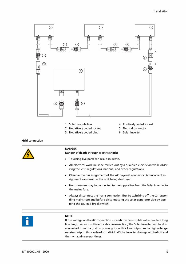
Connection example:
8
18 NT 10000...NT 12000
Installation
1 Solar module box2 Negatively coded socket3 Negatively coded plug
4 Positively coded socket5 Neutral connector6 Solar Inverter
Grid connection
DANGERDanger of death through electric shock!
Touching live parts can result in death.
All electrical work must be carried out by a qualified electrician while obser-ving the VDE regulations, national and other regulations.
Observe the pin assignment of the AC bayonet connector. An incorrect as-signment can result in the unit being destroyed.
No consumers may be connected to the supply line from the Solar Inverter to the mains fuse.
Always disconnect the mains connection first by switching off the correspon-ding mains fuse and before disconnecting the solar generator side by ope-ning the DC load break switch.
NOTEIf the voltage on the AC connection exceeds the permissible value due to a long line length or an insufficient cable cross-section, the Solar Inverter will be dis-connected from the grid. In power grids with a low output and a high solar ge-nerator output, this can lead to individual Solar Inverters being switched off and then on again several times.
1 1 1
6
5 2 5 2
5
4
42
2
3
N
+
NT 10000...NT 12000 19
Installation
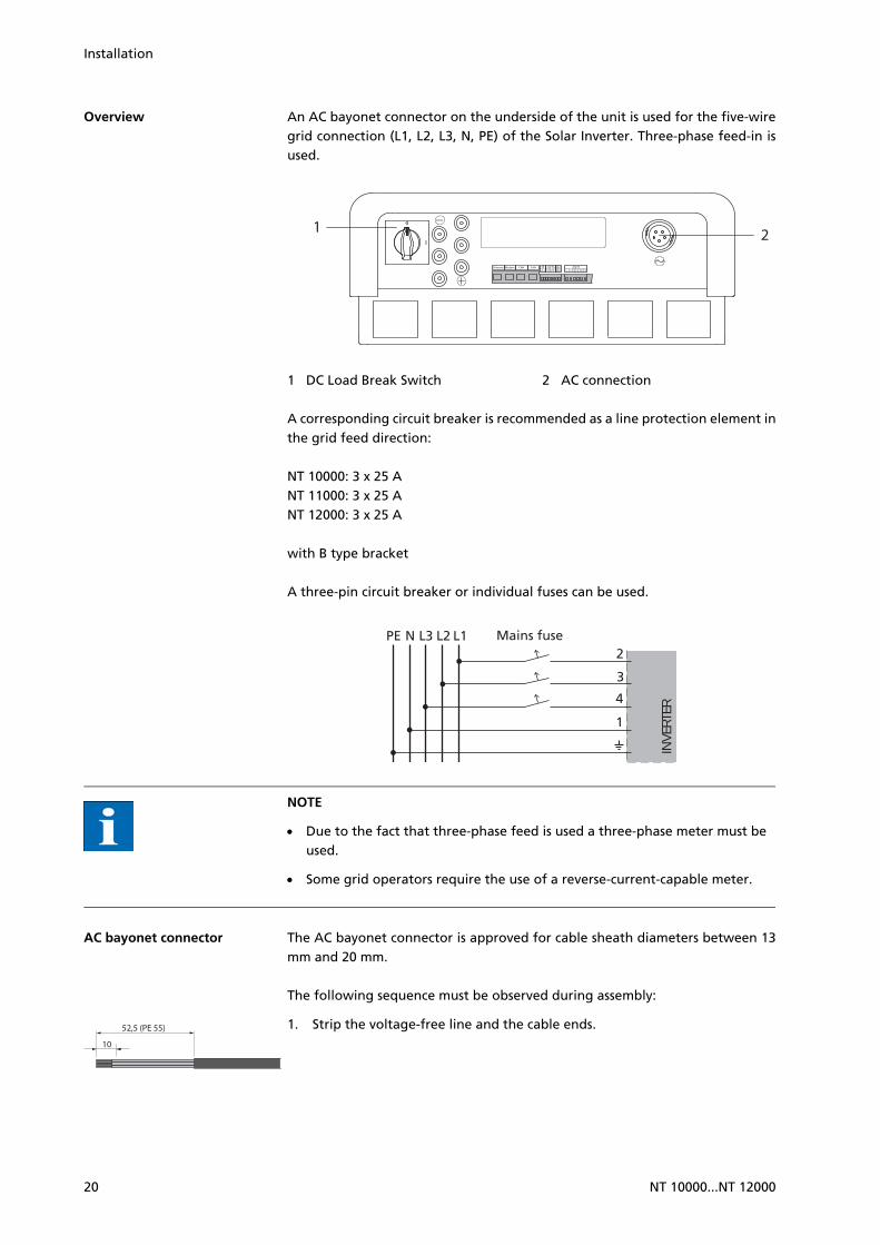
Overview An AC bayonet connector on the underside of the unit is used for the five-wiregrid connection (L1, L2, L3, N, PE) of the Solar Inverter. Three-phase feed-in isused.
1 DC Load Break Switch 2 AC connection
A corresponding circuit breaker is recommended as a line protection element inthe grid feed direction:
NT 10000: 3 x 25 A NT 11000: 3 x 25 A NT 12000: 3 x 25 A
with B type bracket
A three-pin circuit breaker or individual fuses can be used.
NOTE
Due to the fact that three-phase feed is used a three-phase meter must be used.
Some grid operators require the use of a reverse-current-capable meter.
AC bayonet connector The AC bayonet connector is approved for cable sheath diameters between 13mm and 20 mm.
The following sequence must be observed during assembly:
1. Strip the voltage-free line and the cable ends.
21
PE N L3 L2 L1
1
4
3
2Mains fuse
INV
ERTE
R
10
52,5 (PE 55)
20 NT 10000...NT 12000

Installation
NOTEFor lines with a cable sheath diameter from 16 to 20 mm, the cable gland must be adapted accordingly. To do this, cut out the inner section of the blue sealing ring.
2. Slide the cable gland and the plug housing onto the cable.
3. Connect the cable ends to the plug terminals in accordance with the pin as-signment. Tightening torque: 0.7 Nm.
CAUTIONObserve the pin assignment of the AC bayonet connector. An incorrect assign-ment can result in the unit being destroyed. The diagram shows the connections inside the AC connector, as indicated by the cut-out at the PE connection.
1 = N (neutral conductor)2 = L1 (feed-in phase)3 = L2 (feed-in phase)
4 = L3 (feed-in phase) = PE (protective earth conductor)
4. Screw plug housing to plug. To do this, push the outer ring of the plug to-ward the connector housing. Tightening torque: 1-2 Nm.
5. Tighten the cable gland.
Tightening torque for cable sheath diameters between 13 and 20 mm: 6 to 8 Nm
NOTEMake sure the line is provided with a strain relief device. When using cables with a diameter of less than 16 mm, the line must be relieved just behind the connector.
12
43
The diagram shows the connections inside the ACconnector, as indicated by thecut-out at the PE connection.
NT 10000...NT 12000 21

Installation
4.3 Installing the communication equipment
The interfaces are located behind the weatherproof connection box on the un-derside of the Solar Inverter.
To open the connection box, loose the centre screw. Then carefully pull way thebox toward the front.
After you have installed the connection cable, close the box again by guidingthe locking hooks into the notches in the housing and then pressing the boxonto the housing.
Retighten the mounting screw.
Interface overview
1 Ethernet connection 2 Modem connection 3 CAN IN 4 CAN OUT 5 S0 interface (pulse output, e.g. for
large display)
6 Terminal for temperature and irra-diance sensor
7 RS485 interface 8 Terminal for alarm relay
Pin assignment
The connectors for the CAN interfaces CAN IN and CAN OUT and for the modeminterface have the following pin assignment:
CAN and modem
21 3 4 8765
CAN modem
Pin Description Meaning Description Meaning
1 N.C. >1 TXh
Ethernet Modem CAN CAN
2 1346 578 2 1346 578 2 1346 578
22 NT 10000...NT 12000

Installation
Networking Solar Inverters via CAN bus
Solar Inverters from the NT, AT und PT series can be networked via the CAN businterface. Use the included Ethernet cable to network the Solar Inverters witheach other. Connect a terminating resistor at the first and last Solar Inverter inthe series. The pluggable terminating resistors are included in the delivery.
1 Terminating resistor connector
The total length of the CAN bus depends on the selected bit rate. The followingtable shows the possible bit rates and the resulting bus lengths.
Solar Inverters of the PT series are delivered with a default setting of 125 kbit/s.The default setting for Solar Inverters of the NT and AT series is 500 kbit/s.
2 CAN_GND 0 V / GND >2 TX1
3 CAN_H Bus line (domi-nant high)
<3 RXh
4 CAN_L_T Termination -4 VCC
5 CAN_H_T Termination -5 GND
6 CANL Bus line (domi-nant low)
<6 RXI
7 CAN_SHLD Optional CAN shield
<7 R1h
8 N.C. <8 R1I
CAN modem
Pin Description Meaning Description Meaning
1 1
Bit rate Bus lengt
100 kbit/s 650 m
125 kbit/s 500 m
250 kbit/s 250 m
500 kbit/s 100 m
NT 10000...NT 12000 23

Installation
NOTEWhen Solar Inverters from different series are networked the bit rate in all units must be identical. The rate can be set via the Solar Inverter display or the Sun-ways Browser.Einstellung der Bitrate über das Display-Menü: Einstellungen - Vernetzung - CAN-BUS - Baudrate
Up to 99 NT, PT and AT series units can be networked via a CAN bus. The fol-lowing table shows the recommended cable cross-sections depending on thebus length and the number of nodes:
In cases where the values specified in the table cannot be adhered to, a CANbridge for boosting the signal must be installed, through which the length ofthe CAN bus can be extended by up to 500 m. The requirement to install a CANbridge is therefore determined by the bus length, the number of nodes and thecable cross-sections.
The CAN bridge is available from Sunways. For further information please con-tact the Technical Hotline.
The CAN bridge subdivides the bus into two physically independent segments.The maximum cable length of each segment is determined by the set bit rate.
Bus length/Number of nodes
32 64 99
100 m 0.25 mm² or AWG 24
0.25 mm² or AWG 24
0.25 mm² or AWG 24
250 m 0.34 mm² or AWG 22
0.5 mm² or AWG 20
0.5 mm² or AWG 20
500 m 0.75 mm² oder AWG 18
0.75 mm² or AWG 18
1.0 mm² or AWG 16
CAN bus
Inverter
XX
Inverter
XX
Inverter
XX
CA
N B
rid
ge
Network length / number of nodes / cable cross-section outside the table values 1 or several CAN bridge(s)
24 NT 10000...NT 12000

Installation
With a bit rate of 125 kbit/s two segments with a maximum length of 500 meach are possible. The total line length can therefore be up to 1 km under idealconditions.
In systems with Solar Inverters from the PT series the CAN bridge can be integ-rated directly in the PT Solar Inverter and supplied via the 24 V DC power supplyunit of the inverter. In systems with AT Solar Inverters and units from the newNT series (900 V) the CAN bridge can be integrated in the AC distribution. In thiscase an external 24 V DC supply is required (power consumption 1.5 W).
Networking Solar Inverters via RS485 interface
For joint monitoring of a solar system with Sunways Solar Inverters from the ol-der NT generation (750 V or 850 V) you can use the RS485 interface integratedin the Solar Inverters. The system networked with the RS485 interface can bemonitored with the Sunways Communicator.
NOTE
Use a twisted pair cable to network the Solar Inverters with each other.
Mount the terminating resistor on the last Solar Inverter.
NT 8000 / 10000: Jumper RS485MATCH
NT 2600 to NT 6000: Jumper JP400
S0 interface The S0 pulse output enables, for example, the connection of a large display(Sunways Display) for displaying the momentary output, the energy yields andthe CO2 reduction.
You can use the S0 interface on the main unit if you want to transmit the entireline yields as a sum to a large display.
The S0 interface is adjusted via the display on the inverter. Go to Settings - Net-work - Interfaces.
RS48
5GN
DRS
485+
RS48
5–
RS48
5GN
DRS
485+
RS48
5–
RS48
5+
RS48
5–
RS48
5+
RS48
5–
NT 8000NT 10000
NT 2600...NT 6000
NT (900 V)or AT
NT (900 V)or AT Sunways
Communicator
NT 10000...NT 12000 25

Installation
NOTE
Please note that the maximum pulse rate may not be greater than 15 pulses/sec. Calculate the pulse rate depending on the size of the solar system using the following formula:
Pulse rate [pulses/kWh] = 50,000 / system size [kWp]
The pulse rate must be set on your Solar Inverter and on the large display.
Temperature and irradiance sensor
The optional addition of an irradiance sensor (model Si-01TC-K from Ingenieur-büro Mencke & Tegtmeyer) with an integrated PT-100 temperature sensor fortemperature measurement enables the acquisition of irradiation data and thecorresponding module temperature and storage in the internal data memory asa 5-minute mean value. This additional measuring unit helps analyse the systemoutput. Based on the values, any errors on the PV generator, e.g. shading or fai-lure of solar cells, can be detected.
The sensor is activated via the display. In the menu Settings - Network - Inter-faces you can select the sensor type in the Irrad. and Temp. field.
Assignment of sensor connection
Sensor connector pin assignment
Sensor connection designation Solar Inverter connection designati-on
Pin 1 Positive-signal temperature Temp
Pin 2 Positive-signal irradiance
Solar
Pin 3 Reference earth V-
Pin 4 Plus connection for +5 V supply
V+
26 NT 10000...NT 12000

Installation
Connecting the alarm relay The Solar Inverters are equipped with a potential-free alarm relay as standard.The relay can be designed as a make-contact element or as a break-contact ele-ment and is actuated for all malfunctions signalled by the device. This ensuresfast, reliable indication of a possible fault in the PV system on site. For PV sys-tems with several Solar Inverters the individual relays can be switched in paralleland connected via a common indicator lamp.
The main unit also signals faults from other units in the CAN network via thealarm relay. It is therefore sufficient for simple alerting to connect the alarm re-lay of the main unit.
CAUTIONThe alarm relay is designed for 230 V/2 A. Higher outputs/voltages can result in the relay being destroyed. The connected signalling unit must be fused separa-tely. The terminals are intended for a cable cross-section of 0.2 mm2 to 1.5 mm2. When dimensioning the cross-section, also take the current consumption of the connected signalling unit into account.
Wiring diagram for a single unit
Wiring diagram for several units
1 Indicator lamp, red 2 Indicator lamp, green
NOTEThe Solar Inverter is supplied by the feed phases from the AC grid. If all feed phases fail simultaneous, the alarm relay cannot respond, despite the fact that there is a fault.
~ 1 2
NO
NO NC
NCCC
~ 1 2
NO
NO NC
NCCC NO
NO NC
NCCC
NT 10000...NT 12000 27

Installation
28 NT 10000...NT 12000

Commissioning
5 Commissioning
5.1 Connecting and disconnecting Solar Inverter
CAUTION
Ensure proper mechanical and electrical installation before commissioning the Solar Inverter.
Check the cables to ensure that they are in sound condition.
Always disconnect the mains connection first by switching off the correspon-ding mains fuse and before disconnecting the solar generator side by ope-ning the DC load break switch.
The Tyco Solarlok connectors on the solar generator side must not be discon-nected under load. First turn the DC load break switch to position 0.
NOTEThe Solar Inverter is supplied from the grid. The Solar Inverter switches on au-tomatically when sufficient solar generator output is available. Corresponding switch-on and switch-off thresholds have been defined for this purpose.
Connecting 1. Establish the grid connection via the external circuit breaker.
2. Switch on the solar generator voltage by closing the DC load break switch (switching position 1). The Solar Inverter starts operating when the input voltage level is adequate.
1 DC Load Break Switch
The operating LED lights up in accordance with the operating state.
The commissioning menu opens when the Solar Inverter is connected for thefirst time.
Disconnecting 1. Interrupt the grid connection by switching off the circuit breaker.
2. Disconnect the solar generator side by opening the DC load break switch (switch position 0).
5.2 Commissioning
The commissioning menu comes up automatically when the Solar Inverter isconnected for the first time. It helps you make the standard settings.
1
NT 10000...NT 12000 29

Commissioning
NOTEFor a better understanding of keyboard operation, please also see the chapter Operation.
The procedure for commissioning the Solar Inverter as a
single unit
and as a main unit and secondary units with several networked units
is described in detail below.
Please note:
Once the system has been commissioned, the country can no longer be changedvia the menu. To change the country retrospectively, please contact the Techni-cal Hotline on Tel +49 (0)7531 996 77-577.
Commissioning single unit
System with one Solar Inverter
1. The commissioning process starts with setting of the display language. Se-lect the language in selection menu with / .
Confirm the selected language with .
2. Select the country in the selection menu with / .
3. Confirm the country of installation with .
NOTEThe Solar Inverter only starts feeding current into the grid once the country has been selected.
Single device
30 NT 10000...NT 12000

Commissioning
4. Select "Single unit" in the selection menu with / .
Confirm with .
5. Set the date and time.
Select the time with . Change the selected number with / and jump to the next number with / .
Apply the set time with and set the date accordingly.
Apply the set date with .
NOTEPlease note that time settings should only be made with caution, as they directly affect data logging. For example, if you set the time back by 1 hour, then the existing data will be overwritten.
6. Setting a password. Select Password with . Default password is:
********
A new password can be set with / / / as an option.
Confirm the password with .
NOTEPlease note: Only digits between 0 – 9 and letters between a – z and A – Z are permitted. The password always has 8 characters. If the password you entered has less than 8 characters, the remaining characters are filled with *. Example:Your password is "Solar". This password has 5 characters. The system automati-cally appends three *, so that the password becomes "Solar***".
7. Completion of commissioning.
Confirm overview with .
Commissioning several net-worked units
System with several Solar In-verters Master Slaves
NT 10000...NT 12000 31

Commissioning
Before commissioning, all units must be interconnected via the CAN bus inter-face. See the chapter on Networking Solar Inverters via CAN bus.
Switch on all units following installation. Start commissioning with the unit youselected as the main unit.
Compatibility between Sun-ways Solar Inverters
The following table provides an overview of which devices can be networkedwith each other and how, and lists any special considerations:
32 NT 10000...NT 12000

Commissioning
Commissioning main unit 1. The commissioning process starts with setting of the display language. Se-
lect the language in selection menu with / .
Confirm the selected language with .
2. Select the country in the selection menu with / .
NT series (900 V) PT series AT series NT series (850 V)
NT series (850 V)
with RS485: Sunways Portal:
with Sunways Communicator
NT with RS485 / PT with CAN bus: Sunways Portal:
connect NTs with Sunways Commu-nicator, PTs with Sunways Modem or DSL/network to the Internet
Sunways Browser: only available for PT
with RS485: Sunways Portal:
with Sunways Communicator
Sunways Monitor
with RS485: Sunways Portal:
with Sunways Communicator
Sunways Monitor: with interface converter
AT series with separate CAN networks: Sunways Browser Sunways Portal:
NT devices (900 V) must be operated in a separate CAN network with in-dependent main unit
with CAN bus: Sunways Browser Sunways Portal The PT Solar In-
verter must be the main unit.
with CAN bus: Sunways Browser Sunways Portal
PT series with separate CAN networks: Sunways Browser Sunways Portal:
NT devices (900 V) must be operated in a separate CAN network with in-dependent main unit
with CAN bus: Sunways Browser Sunways Portal
NT series (900 V)
with CAN bus(CANopen/CiA437): Sunways Browser Sunways Portal
NT 10000...NT 12000 33

Commissioning
3. Confirm the country of installation with .
NOTEThe Solar Inverter only starts feeding current into the grid once the country has been selected.
4. Select "Main unit" in the selection menu with / .
Confirm with .
NOTEThe other units in the CAN network are automatically configured as secondary units.
5. Set the date and time centrally for all connected units.
Select the time with . Change the selected number with / and jump to the next number with / .
Apply the set time with and set the date accordingly.
Apply the set date with .
NOTEPlease note that time settings should only be made with caution, as they directly affect data logging. For example, if you set the time back by 1 hour, then the existing data will be overwritten.
6. Device search at the main unit.
The IDs for the secondary units can be allocated automatically or manually. When manual ID allocation is selected the ID must be requested at the se-condary unit. With automatic ID allocation this step is not required, since the device IDs are assigned automatically.
The following display appears during the device search:
Units = total number of units found in the CAN network
In network = number of configured units
After the main unit has found all connected secondary unit, these must be configured before commissioning of the main unit is continued.
34 NT 10000...NT 12000

Commissioning
Confirm with .
NOTEDepending on the side of the network, it may take a moment until the main unit has found all secondary units and added them to the list.
7. Set password centrally for all connected units. Select Password with .
Default password is:
********
A new password can be set with / / / as an option.
Confirm the password with .
NOTEPlease note: Only digits between 0 – 9 and letters between a – z and A – Z are permitted. The password always has 8 characters. If the password you entered has less than 8 characters, the remaining characters are filled with *. Example:Your password is "Solar". This password has 5 characters. The system automati-cally appends three *, so that the password becomes "Solar***".
8. Completion of commissioning
Confirm overview with .
Commissioning secondary units
The procedure for commissioning secondary units depends on the type of devicesearch. Once a main unit has been defined and manual ID allocation was selec-ted (e.g. for systems with AT and PT), each secondary unit automatically displaysa CAN ID request.
If automatic ID allocation was selected on the main unit, this step is skipped. Inthis case completion of commissioning must be confirmed with at each se-condary unit.
1. For manual device search only: Request CAN ID. Request the next higher free ID from the main unit with or the next lower free ID with .
The main unit assigns a free ID to the secondary unit. Confirm the ID within 5 seconds with .
Request further IDs with / .
Confirm the CAN ID with within 5 seconds.
NT 10000...NT 12000 35

Commissioning
NOTEThe data for the individual secondary units can be assigned in the Sunways Browser and in the menu of the main unit based on the IDs. The CAN-ID 1 is automatically assigned to the main unit. This means the secon-dary units can be assigned IDs from 2 to 99. Commissioning cannot be continued until after an ID has been requested from the main unit.
2. Completion of commissioning
Confirm overview with .
3. Commissioning all other secondary units as described above
Later commissioning If you add new units or replace existing ones in your solar system, then you candisplay the unit list in the display on the master under Settings - Network - CANbus. The new unit can then be put into operation in accordance with the de-scription for commissioning slaves.
36 NT 10000...NT 12000

Operation
6 Operation
6.1 General information
Operating elements
Operating field The Solar Inverter is operated via the control panel at the front.
1 LCD display (lighted)2 Operating LED
3 Keyboard
LCD display A graphics-capable, monochrome dot matrix display is integrated in the opera-ting field. In standard mode the momentary output, daily yield and status aredisplayed. The bar graph shows the energy feed-in of the current day.
Press any key to activate the display lighting.
If no key is pressed for approx. 1 minute, the display lighting goes out.
NOTEImportant!The LCD display is not a calibrated measuring device. A deviation of several per-cent is inherent in the system. Exact accounting of the data with the power sup-ply company requires a calibrated meter.
Keyboard The keyboard can be used to navigate in the menu, edit text fields, select entriesfrom lists and enter numbers consecutively and digit by digit. User entries canonly be made if the value to be changed is selected. The cursor changes visiblyin the editing mode and indicates the digit to be changed.
Operating LED The combined red/green LED indicates the status of the Solar Inverter:
LED off
1 2 3
Solar Inverter NT
button Scroll up
button Scroll down
button Select menu item
button Back one menu level
button Select a menu item and confirm your entry
button Quit
NT 10000...NT 12000 37

Operation
Solar inverter is not active (night mode)
LED green, continuously lit
Solar inverter is active and feeds into power grid (MPP mode)
LED green, flashing
Solar inverter is active and feeds into power grid, although with current, out-put or temperature limitation
LED red, continuously lit
A fault has occurred (malfunction)
LED red, flashing
Warning
Standard screen (single unit) The standard screen is always shown when no keyboard entry is made for morethan 1 minute. It can also be called up manually with the menu item Solar Inver-ter – Instantaneous Values.
The standard screen shows the most important data at a glance. In the first lineyou see the momentary feed-in power. In the second line the fed-in energy forthe day is shown.
The status signals the unit status with the following messages:
MPP Feeding in MPP mode
OK All networked devices are feeding in
AC cur.lim. Feeding with AC current limitation
AC cur.lim. Feeding with DC current limitation
Temp.lim. Feeding with temperature limitation
Output lim. Feeding with output limitation
Feed. Feed
Warning A warning has been output
Error An error has occurred
Night Night mode
Start Device initialisation phase
COM-Upd The communication software is being updated
Reg.Upd. The control software is being updated
Ueb.Upd. The monitoring software is being updated
Wif Upd. The web interface is being updated
DWifUpd. The dynamic web interface is being updated
MenSUpd. The menu structure is being updated
MenFUpd. The menu error texts are being updated
WifSUpd. The web interface status texts are being updated
RWP.Upd. The read/write parameters are being updated
38 NT 10000...NT 12000

Operation
The graphic in the lower section of the screen shows the energy fed in for theday as a bar graph. The current period is shown as a flashing bar, as it is still in-creasing.
Standard screen (system) You can view the system data for a CAN-networked system with this screen.
Next to the total current system output, you also see the energy yield of yoursolar system and any status messages of all connected units. These are providedwith the inverter number. An ‘M‘ means that the error has occurred on the mainunit.
NOTE
The various functions are accessed via the menu. The main menu is opened from the standard screen by pressing twice.
You can return to the standard screen at any time by pressing and holding the key.
If a status message is shown you can open the error list directly with .
You can access other instantaneous values from the standard screen with and .
Access rights Die Bedienung des Solar-Inverters ist in verschiedene, durch Passwörter ge-schützte Bereiche gegliedert.
Das Passwort ist 8-stellig.
Das Passwort kann im Menüpunkt «Einstellungen – Anmeldung» eingegebenwerden.
NOTEErfolgt nach der Eingabe des Passwortes keine Eingabe über die Tastatur, ist nach etwa 5 Minuten eine erneute Eingabe des Passwortes erforderlich.
ROP.Upd. The read only parameters are being updated
ParaUpd. Parameter update
Min Upd. Update of the minute values in the data logger files
Day Upd. Update of the daily values in the data logger files
Mon Upd. Update of the monthly values in the data logger files
YearUpd. Update of the annual values in the data logger files
SMinUpd. Update of the minute values in the system data logger files
SDayUpd. Update of the daily values in the system data logger files
SMonUpd. Update of the monthly values in the system data logger files
SYerUpd. Update of the annual values in the system data logger files
NT 10000...NT 12000 39

Operation
Customer area The customer password must be entered to access this area. All settings can bemade which are required for installation and commissioning of the Solar Inver-ter.
NOTEThe password for the customer area is:********The password is preset and is directly confirmed with .As an option you can assign a personal password in the Commissioning menu. Only digits between 0 – 9 and letters between a – z and A – Z are permitted.The password always has 8 characters. If the password you entered has less than 8 characters, the remaining characters are filled with *.Example:Your password is "Solar". This password has 5 characters. The system automati-cally appends three *, so that the password becomes "Solar***".
Installer area In this section the installer can make special settings on the Solar Inverter whichare only possible after consulting the Technical Hotline. Request a device-speci-fic password from the Technical Hotline.
Technical hotline +49 (0) 7531 996 77-577
Country password Changing the country setting after commissioning requires an installer pass-word, which can be obtained from the Technical Hotline. The last 8 digits of theinstaller password form the country password.
NOTEEach country has specific regulations for grid connection of inverters. By selec-ting the country the settings for the switch-off parameters are set according to the standards for this country.
Menu structure You can access all screens on the Solar Inverter with the menu. The menu is ope-ned by pressing the left arrow key from the standard screen.
40 NT 10000...NT 12000

Operation
NOTE
The areas highlighted in grey are only available in the main unit
*) after entering the customer password. Standard password: ******** (= 8 asterisks)
**) This is only shown if the configured country of installation is Italy.
Overview of screen displays
Instantaneous values Energy yield Events History Information
Instantaneous values Energy yield Events System history System info
General information Login Network* Commissioning*Change country*Self-testing**
Yield for week Yield for 15 days Yield for month AC output DC values AC valuesMax. output
Unit 1 Feed Unit 2 Feed
Ethernet CAN bus Interfaces
Yield for week Yield for 15 days Yield for month Total outputMax. output
Firmware Memory Mode
Language LCD contrast Date/Time* Receiving time* Firmware* New password*
START
Unit 3 FeedInstantaneous values 2
RS485 bus
Solar InverterSolar systemSettings
Standard screen
Display Description Calling Menu
Instantaneous Values – Unit
NT 10000...NT 12000 41

Operation
Current feed-in power, daily energy yield and unit statusMPP: Feeding in MPP mode
The screen appears automatically if no key is pressed for several minutes. Solar inverter – Instantaneous values
Shows the output, the power fed in today, and the DC and AC voltage of power unit 1
Solar inverter – Instantaneous values –
Shows the output, the power fed in today, and the DC and AC voltage of power unit 2
Solar inverter – Instantaneous values –
Shows the output, the power fed in today, and the DC and AC voltage of power unit 3
Solar inverter – Instantaneous values –
Interior temperature of unit (Temp.Inv.) and temperature and irra-diation values (if sensor is connected)
Solar inverter – Instantaneous values –
Instantaneous values – Yields
AC yields and operating hours from today, yesterday and the day before yesterday
Solar inverter – Energy yield
AC yields and operating hours for the current week, the previous week, the current month and the previous month
Solar inverter – Energy yield –
AC yields for the current year and the previous year
Solar inverter – Energy yield –
Events – Unit
Select starting data for event display Solar inverter – Events
Display event list Solar inverter – Events –
Display Description Calling Menu
42 NT 10000...NT 12000

Operation
Display event details (error number, data, starting time, duration and number of occurrences per day)
Solar inverter – Events – –
History – Unit
Daily yield for 1 week Solar inverter – History – Yield for week
Daily yields for 15 days Solar inverter – History – Yield for 15 days
Monthly yields Solar inverter – History – Yield for month
AC output (5-min. values) Solar inverter – History – AC output
DC voltage (5-min. values) Solar inverter – History – DC output
DC current (5-min. values) Solar inverter – History – DC output –
AC voltage (5-min. values) Solar inverter – History – AC output
AC current (5-min. values) Solar inverter – History – AC output –
Maximum output Solar Inverter – History – Max. output
Information – Unit
Display Description Calling Menu
NT 10000...NT 12000 43

Operation
Firmware Solar Inverter – Information – Firmwa-re
Memory card Solar Inverter – Information – Memory
Device mode Solar Inverter – Information – Mode
Instantaneous values – Solar system (display only main unit)
Current system feed-in power, daily energy yield and system status
The screen appears automatically on the main unit if no key is pressed for several minutes. Solar system – Instantaneous values
Yields – Solar system (display only main unit)
AC system yields and operating hours from today, yesterday and the day be-fore yesterday
Solar system – Energy yield
AC system yields for the current week, the previous week, the current month and the previous month
Solar system – Energy yield –
AC system yields for the current year and the previous year
Solar system – Energy yield –
Events – Solar system (display only main unit)
Select starting data for system event display
Solar system – Events
Display event list for entire system Solar system – Events –
Display event details (error number, data, starting time, duration and number of occurrences per day)
Solar system – Events – –
Display Description Calling Menu
44 NT 10000...NT 12000

Operation
History – Solar system (display only main unit)
Solar system daily yield for 1 week Solar system – System history – Yield for week
Solar system daily yield for 15 days Solar system – System history – Yield for 15 days
Solar system monthly yields Solar system – System history – Yield for month
Solar system AC output (5-min. values) Solar system – System history – AC ca-pacity
Maximum system output (daily maxi-mum values)
Solar system – System history – Max. capacity
System info – Solar system (display only main unit)
Unit list for selecting a unit Solar system – System info
Selection of information Solar system – System info –
Firmware Solar system – System info – Firmware
Memory card Solar system – System info – Memory
Device mode Solar system – System info – Mode
Settings – General
Display Description Calling Menu
NT 10000...NT 12000 45

Operation
Display language Settings – General – Language
LCD contrast Settings – General – LCD contrast
Set date/time (only possible with customer pass-word)
Settings – General – Date/Time
Set receiving time (starting time and duration in which the unit can also be addressed in the night mode via the network). (only possible with customer pass-word)
Settings – General – Receiving time
Firmware versions Settings – General – Firmware
Changing the customer password (only possible with customer pass-word)
Settings – General – Password
Settings – Login
Password entry to access advanced settings (necessary for commissioning)
Settings – Login
Settings – Network (only possible with customer password)
Network settings (Screen 1): Activate DHCP for the automatic IP address set-ting or enter IP address manually
Settings – Network – Ethernet
Network settings (Screen 2) Settings – Network – Ethernet –
Only for secondary unit Settings – Network – CAN bus
Display Description Calling Menu
46 NT 10000...NT 12000

Operation
Error messages The Solar Inverter indicates malfunctions in the LCD display and saves these inthe internal error memory.
The fault display consists of a number and a short description. Based on the firstnumber you can quickly recognise which area the fault has occurred in:
1: Solar generator fault
2: AC grid fault
3: Inverter fault
4: Interface/communication fault
5: Interface/communication warnings
6: Remote access warnings
9: Service fault
Only for secondary unit with manual CAN ID setting: CAN ID request
Settings – Network – CAN bus – CAN ID
Main unit only Settings – Network – CAN bus
Selection at the main unit: Type of ID allocation for the secondary units
Settings – Network – CAN bus – Secon-dary units
Setting the baud rate Settings – Network – CAN bus – Baud rate
Function test for the CAN connection Settings – Network – CAN bus – Diag-nostics
Setting of the irradiance and tempe-rature sensor and configuration of the S0 pulse output
Settings – Network – Interfaces
Display Description Calling Menu
NT 10000...NT 12000 47

Operation
If an error is shown in the standard display, then you can look up the exact errormessage in the menu under Solar inverter – Events.
NOTE
A restart may be attempted in the event of an error message.
Please note the serial number of the unit and the error number before con-tacting the Technical Hotline.
The Technical Hotline can be contacted on +49 (0) 7531 996 77-577 between 7.30 am and 6 pm CET during weekdays.
48 NT 10000...NT 12000

Operation
Display message Description Cause and possible remedies
Solar generator fault
101:U-DC max. Your NT Solar Inverter is approved for a maximum solar generator open-circuit voltage of 900 V. All DC input compo-nents are adequately dimensioned with a safety margin. If the threshold is excee-ded, the Solar Inverter stops feeding.
The maximum DC voltage was exceeded. Check the dimensioning of your PV
generator.Too many modules are connected in se-ries. Reduce the number of modules and
re-commission the system.
102:Insulat. Before each connection, your Solar Inver-ter checks the PV system for a possible earth or insulation fault. If this kind of er-ror is detected, no feed in takes place. The mode of operation is compliant with DIN V VDE 0126-1-1.
The Solar Inverter has discovered an insu-lation fault in the PV system during run-up. Check your PV system for possible in-
sulation faults (damaged DC cables etc.).
The measured insulation resistance must be at least 900 kΩ.
103:AFI>30mA105:AFI>60mA106:AFI150mA
Your Solar Inverter is equipped with an AC/DC sensitive AFI according to DIN VDE 0126-1-1. The monitoring unit has detec-ted a relative residual current increase.
A sudden residual current increase has oc-curred during Solar Inverter operation. Check your PV system for possible in-
sulation faults.
104:AFI>0.3A Your Solar Inverter is equipped with an AC/DC sensitive AFI according to DIN VDE 0126-1-1. This monitoring unit has detec-ted an absolute residual current of >300 mA.
A residual current has occurred during So-lar Inverter operation. Check your PV system for possible in-
sulation faults.
AC grid fault
201:Surge e. Your Solar Inverter continuously moni-tors the quality of the AC grid. During high voltage peaks on the phase feeding in, the Solar Inverter stops feeding and attempts a restart.
The Solar Inverter has detected a high voltage peak on the phase feeding in. After troubleshooting the Solar In-
verter restarts automatically. Should the error occur frequently, please contact your power supply company.
A monitoring phase and a neutral con-ductor were interchanged during connec-tion of the AC side.
202:UAC1>10% Your Solar Inverter continually monitors the voltage level of the phase feeding in. If the maximum permissible limit is excee-ded, the Solar Inverter stops feeding and does not start up again until the voltage value drops below the maximum permis-sible limit.
The cable cross-section in the AC supply line to the Solar Inverter is too small. Your inverter feeds into a spur line, which is insufficiently dimensioned. Check the design of your grid connec-
tion (energy meter) or the grid feed point to your power supply company (PSC).
Ask your power supply company (PSC) about grid stability and design.
NT 10000...NT 12000 49

Operation
203:UAC1>Max205:UAC2>Max207:UAC3>Max
Your Solar Inverter continuously moni-tors the voltage levels for feed phases L1, L2 and L3. If the maximum permissible li-mit is exceeded, the Solar Inverter stops feeding and does not start up again until the voltage value drops below the maxi-mum permissible limit.
The cable cross-section in the AC supply line to the Solar Inverter is too small. Your inverter feeds into a spur line, which is insufficiently dimensioned. Check the design of your grid connec-
tion (energy meter) or the grid feed point to your power supply company (PSC).
Ask your power supply company (PSC) about grid stability and design.
204:UAC1<Min206:UAC2<Min208:UAC3<Min
Your Solar Inverter continuously moni-tors the voltage levels for feed phases L1, L2 and L3. If the voltage falls below the minimum permissible limit, the Solar In-verter stops feeding and does not start up again until the voltage value exceeds the minimum limit value. If the voltage drops below 160 V, the supply is no longer ade-quate for the Solar Inverter.
Ask your power supply company (PSC) about grid stability and design.
210:Frq1>Max211:Frq1<Min
The Solar Inverter continually monitors the grid frequency of the phase feeding in. If this is outside the permitted range, the Solar Inverter stops feeding and does not start up again until the value is within the tolerance range.
Ask your power supply company (PSC) about grid stability and design.
212:DC share Your Solar Inverter continually monitors the quality of current fed in. If an increa-sed DC share is found in the current fed in, the Solar Inverter stops feeding.
Restart the Solar Inverter.If the error still occurs, please contact the Technical Hotline. The phone number is provided on the back of the manual.
213:UAC1>10%(Warning)
The voltage of the phase feeding in is higher than 10% above the nominal va-lue. If this is the case for longer than ten minutes, the inverter stops feeding and does not switch on again until the volta-ge drops below this limit again.
The cable cross-section in the AC supply line to the Solar Inverter is too small. Your PV system feeds into a spur line, which is insufficiently dimensioned. Ask your power supply company
(PSC) about grid stability and design. Check the design of your grid connec-
tion (energy meter) or the grid feed point to your power supply company (PSC).
224:AC P. fail Your Solar Inverter has detected a mains power failure.
Ask your power supply company (PSC) about grid stability and design.
Display message Description Cause and possible remedies
50 NT 10000...NT 12000

Operation
225:UV excon226:OV excon
Your Solar Inverter is equipped with a high-quality redundant grid monitoring function according to DIN V VDE 0126-1-1 and constantly monitors the grid. If one of the phases fails, or if the phase positi-on between the individual conductors changes, the Solar Inverter stops feeding and does not start up again until the er-ror is eliminated.
Check phases L2 and L3. Ask your power supply company
(PSC) about grid stability and design.
227:L1 Your Solar Inverter continuously moni-tors the output current. Excessive current rise was detected.
Ask your power supply company (PSC) about grid stability and design.
Inverter fault
301:AFI over The integrated sensor for measuring the residual current has been operated out-side its measuring range.
A residual current was detected during start-up. Restart the Solar Inverter. If the error still occurs, please contact the Technical Hotline. The phone number is provided on the back of the manual.
303:Overtmp. Your Solar Inverter is designed for an am-bient temperature of up to +40?. When a specified temperature threshold of the heat sink is reached, the feed line is line-arly reduced in size. Should the heat sink temperature nevertheless continue to in-crease, feeding is stopped. After the heat sink temperature drops, the Solar Inverter starts up again automatically.
The maximum permissible ambient tem-perature has been exceeded. The installation location is not suitab-
le. Please find another installation lo-cation.
The air circulation requirement was not taken into account during installation. Clean the Solar Inverter, if dirt pre-
vents cooling. Observe the installation distances
specified in the manual. Objects were laid on the heat sink and unimpaired convection was prevented. Remove the objects.
304:Grid re. The NT Solar Inverter always checks the function of the mains relay before it is switched on. An error was detected du-ring this check.
Restart the Solar Inverter.If the error still occurs, please contact the Technical Hotline. The phone number is provided on the back of the manual.
305:AFI test The NT Solar Inverter always checks the function of its residual-current monito-ring unit before it is switched on. An error was detected during this check.
Restart the Solar Inverter.If the error still occurs, please contact the Technical Hotline. The phone number is provided on the back of the manual.
Display message Description Cause and possible remedies
NT 10000...NT 12000 51

Operation
306:T. meas. The NT Solar Inverter is equipped with a temperature sensor that monitors the heat sink temperature. This message ap-pears if the sensor reports a value outside its value range or if the sensor cable is da-maged.
The ambient temperature of the Solar In-verter is outside the permissible range (< -25°C). Wait until the temperature is back in
the permissible range. A cable break has occurred in the sensor which monitors the heat sink tempera-ture. Please contact the Technical Hotline.
The phone number is provided on the back of the manual.
307:Overtmp.(Warning)
Your Solar Inverter is designed for an am-bient temperature of up to +45?. When a specified temperature threshold of the heat sink is reached, the feed line is line-arly reduced in size. Should the heat sink temperature nevertheless continue to in-crease, feeding is stopped. This warning appears when the current heat sink tem-perature is just below the switch-off threshold.
The maximum permissible ambient tem-perature has been exceeded. The installation location is not suitab-
le. Please find another installation lo-cation.
The air circulation requirement was not taken into account during installation. Clean the Solar Inverter, if dirt pre-
vents cooling. Observe the installation distances
specified in the manual. Objects were laid on the heat sink and unimpaired convection was prevented. Remove the objects.
309:control The software version of the control soft-ware is incompatible.
Carry out a software update.
310:no config No country is set. Contact the Technical Hotline for the ins-taller password. The phone number is provided on the back of the manual. Re-set the country of installation according to the explanatory notes in section 4.2 Commissioning.
Interface/communication fault
401:SD card The Solar Inverter cannot find an SD card. Restart the Solar Inverter.If the error still occurs, please contact the Technical Hotline. The phone number is provided on the back of the manual.
402:SD card The SD card is write-protected. Restart the Solar Inverter. If the error still occurs, please contact the Technical Hotline. The phone number is provided on the back of the manual.
403:CAN user Communication error with CAN user. Check whether an error has occurred in the secondary CAN unit. Restart the secondary unit and main unit if necessary.
Display message Description Cause and possible remedies
52 NT 10000...NT 12000

Operation
404:CAN bus CAN bus not in operation. No communication is possible via the CAN bus. Check the bus cables and termination
resistors. Check whether the maximum line
lengths are within the permitted li-mits.
Check whether bus cables were ins-talled parallel to power cables. Sepa-rate bus lines and power cable from each other spatially if necessary.
405:CAN user CAN user does not respond. Check whether an error has occurred in the secondary CAN unit. Restart the secondary unit and main unit if necessary.
406:file def Language file could not be loaded. Restart your Solar Inverter. Carry out a software update for the language file.
407:file def Website could not be loaded. Restart your Solar Inverter. Install the latest file for the website via a soft-ware update.
408:file def File with error messages could not be loa-ded.
Restart your Solar Inverter. Install the latest file for the error messages via a software update.
409:CAN-ID Two Solar Inverters were assigned the same ID.
Select one of the two devices with identical CAN ID and set it to Single Unit mode, thereby deactivating the CAN ID.
Then set the device directly in to Se-condary Unit mode and assign a new CAN ID.
Interface/communication warnings
501:Solar(Warning)
No sensor found on sensor channel 1 (so-lar).
If a sensor is connected: Check the sensor connection. If no sensor is connected: Check the configuration via the Sun-
ways Browser.
502:Temp.(Warning)
No sensor found on sensor channel 2 (Temperature).
If a sensor is connected: Check the sensor connection. If no sensor is connected: Check the configuration via the Sun-
ways Browser.
Display message Description Cause and possible remedies
NT 10000...NT 12000 53

Operation
503:CAN com.(Warning)
Communication malfunctions occur re-peatedly on the CAN bus.
A malfunction occurs in the data trans-mission on the CAN bus. However, a data exchange continues to be possible. Check whether all bus line connectors
and terminating resistors are moun-ted properly.
Check whether bus cables were ins-talled parallel to power cables. Sepa-rate bus lines and power cable from each other spatially if necessary.
504:CAN cfg.(Warning)
CAN bus is in the configuration mode. No measured values are transferred.
At least one unit is in the menu item Set-tings – Network – CAN bus. Close this menu in all units.
505:SMTP ser.(Warning)
SMTP server cannot be reached An error occurred during e-mail delivery. Re-attempting e-mail delivery. If the fault recurs check the e-mail
settings via the Sunways Browser 506:SMTP soc.(Warning)
SMTP no socket available
507:SMTP cm.(Warning)
SMTP faulty communication with server
508:DNS fehl.(Warning)
DNS has failed Communication fault between the integ-rated web server and an Internet browser in conjunction with the Sunways browser.These warnings are non-critical and can be ignored if they only occur occasionally. These warnings have no influence on the energy production of the inverter.
509:HTTP con.(Warning)
HTTP client connection has failed
510:HTTP aut.(Warning)
HTTP client authorisation has failed
511:HTTP tim.(Warning)
HTTP client timeout
512:HTTP soc.(Warning)
HTTP client no socket available
513:HTTP soc.(Warning)
HTTP client error with socket
514:HTTP met.(Warning)
HTTP client incorrect method
515:HTTP pro.(Warning)
HTTP client error with protocol
516:HTTP wr.(Warning)
HTTP client write error
517:HTTP re.(Warning)
HTTP client read error
518:CAN init.(Warning)
CAN initialisation error CAN bus initialisation fault during device startup. Restart the Solar Inverter. If the error still occurs, please contact the Technical Hotline. The phone number is provided on the back of the manual.
Display message Description Cause and possible remedies
54 NT 10000...NT 12000

Operation
6.2 System monitoring
General information The basis for the system monitoring is the data logger integrated in the NT SolarInverter. The Solar Inverters of the NT series offer a wide range of monitoringoptions for your solar system:
The Sunways browser can display instantaneous values, stored operating data and settings.
With active alerting information about faults in the solar system can be sent to a selected recipient via e-mail.
Via the Sunways Portal connection the NT Solar Inverter can send the opera-ting data of your solar system to the Sunways Portal on a daily basis without additional hardware. In this way you can monitor your yields via the Internet from wherever you are.
Three networking options are available for access to the system monitoringfunction:
Direct connection via an Ethernet cable (see section Direct Ethernet connec-tion) or internal network (see section Connection via an existing Ethernet network)
519:Time syn(Warning)
Time synchronisation with the NTP server has failed
Firewall port 123 is blocked. Select an alternative time server
Remote access warnings
601:limit K2(Warning)
The output power of your Solar Inverter is limited to the threshold for relay K2 stored in the Sunways Browser, as speci-fied by your power supply company.
Contact your energy supplier regar-ding compensation depending on the duration of the problem.
602:limit K3(Warning)
The output power of your Solar Inverter is limited to the threshold for relay K3 stored in the Sunways Browser, as speci-fied by your power supply company.
Contact your energy supplier regarding compensation depending on the durati-on of the problem.
603:limit K4(Warning)
The output power of your Solar Inverter is limited to the threshold for relay K4 stored in the Sunways Browser, as speci-fied by your power supply company.
Contact your energy supplier regarding compensation depending on the durati-on of the problem.
Service fault
9xx:Service A service error has occurred. Disconnect the Solar Inverter from the grid and from the solar generator and reconnect it.
If the error occurs again, please contact the Technical Hotline. The phone number is provided on the back of the manual.
Display message Description Cause and possible remedies
NT 10000...NT 12000 55

Operation
NOTEWith a direct connection or an internal network without gateway to the Inter-net the Solar Inverter is unable to send e-mails. Portal connection and active alerting is therefore not possible.
Connection via Internet, e.g. via a DSL connection for the Solar Inverter (see section Remote access via a DSL router)
Connection via a Sunways modem (see section Connection via a Sunways mo-dem)
Integrated data logger The data logger integrated in the NT Solar Inverter stores the operating data ofyour solar system. In addition to 5-minute mean values, energy yields are alsostored as 5-minute, daily, weekly, monthly and annual values. Up to 200 statuschanges (warnings and errors with start and end ) are also stored. Each data re-cord contains the data and time. The data logger is designed as a circulating me-mory, i.e. the respective oldest data are overwritten with new data.
Operating data (5-min. ave-rage values)
With this data memory volume approx. 30 days' worth of values can be storedbefore the first value in the ring buffer is overwritten again.
Energy Yields
Status messages
Direct Ethernet connection The Solar Inverters are equipped with an Ethernet interface as standard for sys-tem monitoring and configuration with a PC.
Number Value
4500 DC current
4500 DC voltage
4500 AC current
4500 AC voltage
4500 AC output
4500 Unit temperature
4500 Module irradiance (opt.)
4500 Module temperature (opt.)
Number Value
4500 5-minute yield
7300 Daily yield
250 Monthly yield
20 Annual yield
1 Total yield since commissioning
Number Value
200 Status changes
56 NT 10000...NT 12000

Operation
Connect your PC and the Solar Inverter using the Ethernet cable provided.X-patch cables can also be used.
The PC is connected to the main unit as standard. Basically all Solar Inverters –including Solar Inverters configured as secondary units or single units – featuretheir own web server, so that a connection with any device can be established.
NOTE
To always find the suitable configuration for installation and commissioning on the PC, we recommend the use of a second network card (e.g. PCI Bus, PCMCIA), which you can configure to match the default setting of the Solar Inverter.
The PC and the Solar Inverter must have matching IP addresses and net masks. The network settings can be adjusted either directly on the Solar In-verter via the LCD display or on your PC.
If two network cards are used the IP addresses must be in separate subnets, e.g. 192.168.30.XXX and 192.168.40.XXX.
Network settings on the Solar Inverter
NOTE
The Solar Inverter is supplied with the following preset IP address: 192.168.30.50
In the default setting the Solar Inverter does not support DHCP (Dynamic Host Configuration Protocol). Therefore, the IP address is not assigned auto-matically. It is possible to activate the DHCP protocol via the Settings menu.
IP addresses may not be assigned twice within the network!
If required you can assign your own IP address for the Solar Inverter via the Set-tings menu.
1. Open the menu Settings – Login.
2. Enter the default password (********, i.e. 8 asterisks) or the password you have assigned.
PC
MasterSlave
INV
ERTE
R
INV
ERTE
R
Max. total CAN bus length:500 m
Max. Ethernetconnection: 100 m
NT 10000...NT 12000 57

Operation
NOTEPlease note: Only digits between 0 – 9 and letters between a – z and A – Z are permitted. The password always has 8 characters. If the password you entered has less than 8 characters, the remaining characters are filled with *. Example:Your password is "Solar". This password has 5 characters. The system automati-cally appends three *, so that the password becomes "Solar***".
3. Open the menu Settings – Network – Ethernet.
4. Enter an IP address suitable for use with your PC. This means the first three number blocks must be identical, and the last number block different.
Example:
If your PC has the IP address 192.168.1.1, assign the IP address 192.168.1.2 to the Solar Inverter
5. Call up additional settings with .
6. Enter the subnet mask 255.255.255.0 here.
7. Enter the IP address of your PC in the gateway.
8. Confirm with .
After the network configuration is completed you can start the Sunways Brow-ser by entering the IP address of the Solar Inverter in the address line of yourweb browser.
Network settings on PC To enable your PC to communicate with the Solar Inverter, you must assign net-work settings. The procedure differs slightly depending on the operating sys-tem. An configuration example under Windows®XP is shown below.
NOTEIP addresses may not be assigned twice within the network!
1. Select Start - Settings.
2. Select Network Connections.
58 NT 10000...NT 12000

Operation
3. Double-click on the LAN connection via which you are connected to the So-lar Inverter.
4. Click in the Status window on Properties.
5. Mark Internet Protocol (TCP/IP) and click on Properties again.
6. Now assign an unused IP address 192.168.30.XXX and enter the subnet mask 255.255.255.0.
7. Click on OK to confirm your entries.
8. In the Status menu item you can check the correctness of your entries and the status of your connection.
NT 10000...NT 12000 59

Operation
After the network configuration is completed you can start the Sunways Brow-ser by entering the IP address of the Solar Inverter in the address line of yourweb browser.
For more complex network configurations please contact your network admi-nistrator.
Connection via an existing Ethernet network
You can integrate the NT Solar Inverter as a network device directly in an exis-ting home or company network.
Connect your PC and the Solar Inverter using a CAT 5 Ethernet patch cable.
The main unit is connected to the network as standard.
With DHCP If a DHCP server is present in your network, you can activate DHCP on the SolarInverter. In this case the Solar Inverter obtains the network settings automati-cally. You can display the assigned IP address via the LCD display (menu Settings– Network – Ethernet).
Without DHCP If there is no DHCP server in your network, you must set an unused IP addresson the NT Solar Inverter (see section Solar inverter network setting settings).
Ask your network administrator for the necessary settings for IP address, netmask and gateway.
After the network configuration is completed you can start the Sunways Brow-ser by entering the IP address of the Solar Inverter in the address line of yourweb browser.
Remote access via a DSL router If a DSL connection or a network with Internet access is available you can makethe Solar Inverter accessible via the Internet.
Requirements:
Your DSL router supports static IP address services such as www.dyndns.org
PC PC
HubSwitchRouter
INV
ERTE
R
INV
ERTE
R
MasterSlave
Max. total CAN bus length:500 m
Max. Ethernet connection:100 m
60 NT 10000...NT 12000

Operation
Your router supports port forwarding.
Procedure:
1. Connect your Solar Inverter with your DSL router. Use a CAT5 Ethernet cable with 1:1 RJ45 sockets. The main unit is connected to the network as stan-dard.
2. Register free of charge, e.g. at www.dyndns.org.
3. Create an alias for accessing your Solar Inverter, e.g. NT-sun-ways.dyndns.org. You can then access your Solar Inverter via this address.
4. Configure your DSL router such that the IP address is regularly reported to www.dyndns.org (follow the procedure described in the manual for your DSL router for this purpose).
5. Configure your DSL router such that it accepts queries from the Internet (e.g. via port 80) and forwards them internally to the Solar Inverter (port forwarding).
6. Also note that the port for access from the Internet set in your firewall must be enabled.
NOTEInstructions for configuring common DSL routers are available for download from the Sunways AG website.
Connection via the Sunways Modem
A modem connection can be used to bridge longer distances during system mo-nitoring and configuration. The Sunways Modem is connected to the Solar In-verter for this purpose. The Sunways Modem is available as an analog, ISDN andGSM type.
1. Connect your Solar Inverter and your PC with a crossed or 1:1 Ethernet con-nection cable, type CAT5 with RJ45 sockets.
NOTEIn a networked system only the main unit should be connected to the remote modem as standard.
2. Connect an external modem to your PC or use the internal modem of the PC, if available. For commissioning please refer to the Sunways Modem user manual.
PC
INV
ERTE
R
modem modem
max. 100 m
NT 10000...NT 12000 61
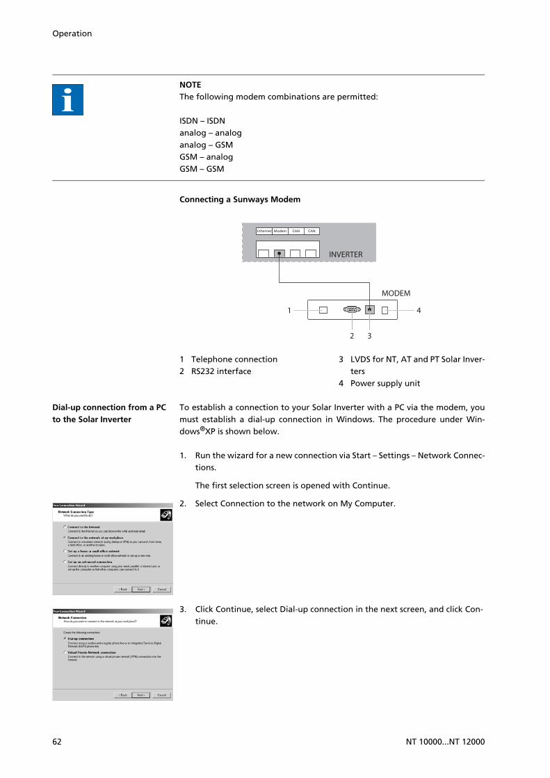
Operation
NOTEThe following modem combinations are permitted:
ISDN – ISDNanalog – analoganalog – GSMGSM – analogGSM – GSM
Connecting a Sunways Modem
1 Telephone connection2 RS232 interface
3 LVDS for NT, AT and PT Solar Inver-ters
4 Power supply unit
Dial-up connection from a PC to the Solar Inverter
To establish a connection to your Solar Inverter with a PC via the modem, youmust establish a dial-up connection in Windows. The procedure under Win-dows®XP is shown below.
1. Run the wizard for a new connection via Start – Settings – Network Connec-tions.
The first selection screen is opened with Continue.
2. Select Connection to the network on My Computer.
3. Click Continue, select Dial-up connection in the next screen, and click Con-tinue.
41
2 3
INVERTER
MODEM
62 NT 10000...NT 12000

Operation
4. A list of the installed modems appears. Select the required modem and click Continue.
5. Enter a connection name and confirm your entry with Continue.
6. Specify the phone number of your Sunways Solar Inverter.
When entering the telephone number, you may need to include one or more digits to connect to an outside line. (An outside line is usually obtai-ned by placing a "0" before the actual telephone number.)
Confirm your entry with Continue.
7. In the next screen you can specify whether or not this connection is to be available to all users of this PC. If in doubt specify "All users" and click Con-tinue.
8. Click the checkbox to place a shortcut on your desktop and click Finish.
9. The connection window appears automatically after finishing the connec-tion. (Alternatively via the icon on your desktop or via Start – Settings – Net-work Connections.)
Further settings are required in the Properties section.
NT 10000...NT 12000 63

Operation
10. First select the Network tab and mark the entry Internet Protocol (TCP/IP) there.
Select Properties.
11. Enter the following data:
Obtain an IP address automatically
Obtain DNS server address automatically
12. Enter "customer" as the user name and the standard password (********, i.e. 8 asterisks) or the password you entered previously.
NOTEThe password matches the customer password on the unit.
13. The connection is established with Dial. After the connection is established you can start the Sunways Browser by entering the IP address of the Solar Inverter in the address line of your web browser.
NOTEIn contrast to the normal IP address for a modem connection the IP address of the Solar Inverter is set to 192.168.20.50 by default.
64 NT 10000...NT 12000
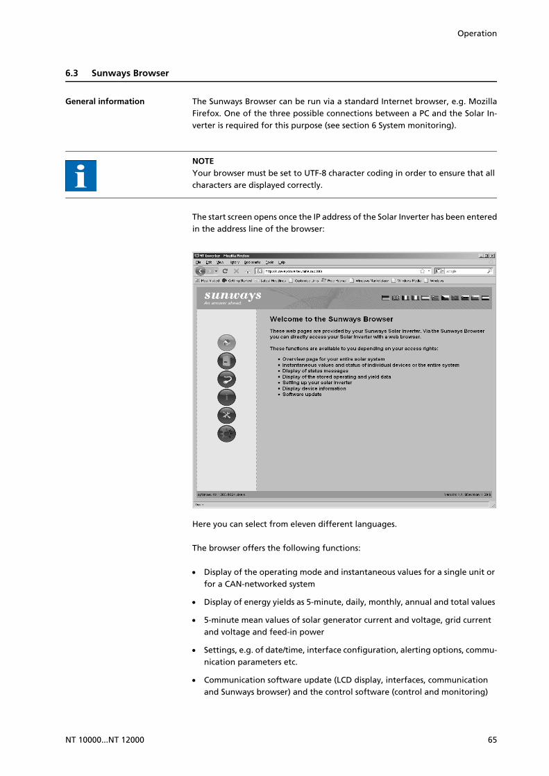
Operation
6.3 Sunways Browser
General information The Sunways Browser can be run via a standard Internet browser, e.g. MozillaFirefox. One of the three possible connections between a PC and the Solar In-verter is required for this purpose (see section 6 System monitoring).
NOTEYour browser must be set to UTF-8 character coding in order to ensure that all characters are displayed correctly.
The start screen opens once the IP address of the Solar Inverter has been enteredin the address line of the browser:
Here you can select from eleven different languages.
The browser offers the following functions:
Display of the operating mode and instantaneous values for a single unit or for a CAN-networked system
Display of energy yields as 5-minute, daily, monthly, annual and total values
5-minute mean values of solar generator current and voltage, grid current and voltage and feed-in power
Settings, e.g. of date/time, interface configuration, alerting options, commu-nication parameters etc.
Communication software update (LCD display, interfaces, communication and Sunways browser) and the control software (control and monitoring)
NT 10000...NT 12000 65

Operation
Access protection The Sunways Browser is provided with password protection so that unautho-rised persons cannot access your Solar Inverter.
The following user data are set in the delivered state:
User: customer
Password: ********
NOTE
It is recommended that you change this password to an 8-character/digit password.
This password is identical to the password entered via the LCD display for set-tings and commissioning.
Only digits between 0 – 9 and letters between a – z and A – Z are permitted.
The password always has 8 characters. If the password you entered has less than 8 characters, the remaining characters are filled with *.
Example:
Your password is "Solar". This password has 5 characters. The system auto-matically appends three *, so that the password becomes "Solar***".
If you cannot remember the password you can request a device-specific pass-word from the Technical Hotline (Tel. 49 (0)7531 996 77-577) so that you can access your Solar Inverter again. In this case you need the serial number and the MAC address, which can be found on the type label.
Overview – Menu Home – Display of start page
Solar Inverter – Display of the instantaneous values, the stored ope-rating data, and the status of the Solar Inverter
Solar System – Displays a system overview with status, total output, yields and access to secondary units (only available if the unit is con-nected with the main unit)
Information – Device information, e.g. serial number
Settings and software update for the unit or the networked system
66 NT 10000...NT 12000
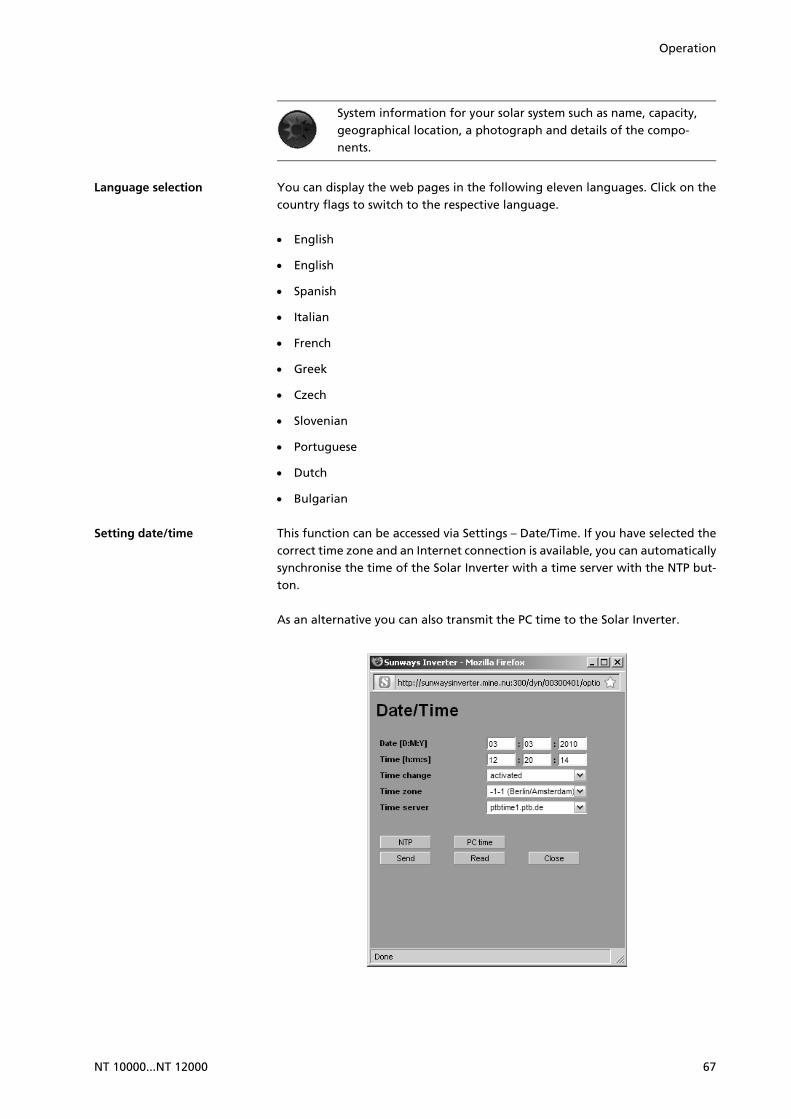
Operation
Language selection You can display the web pages in the following eleven languages. Click on thecountry flags to switch to the respective language.
English
English
Spanish
Italian
French
Greek
Czech
Slovenian
Portuguese
Dutch
Bulgarian
Setting date/time This function can be accessed via Settings – Date/Time. If you have selected thecorrect time zone and an Internet connection is available, you can automaticallysynchronise the time of the Solar Inverter with a time server with the NTP but-ton.
As an alternative you can also transmit the PC time to the Solar Inverter.
System information for your solar system such as name, capacity, geographical location, a photograph and details of the compo-nents.
NT 10000...NT 12000 67
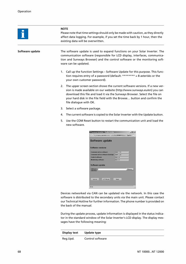
Operation
NOTEPlease note that time settings should only be made with caution, as they directly affect data logging. For example, if you set the time back by 1 hour, then the existing data will be overwritten.
Software update The software update is used to expand functions on your Solar Inverter. Thecommunication software (responsible for LCD display, interfaces, communica-tion and Sunways Browser) and the control software or the monitoring soft-ware can be updated.
1. Call up the function Settings – Software Update for this purpose. This func-tion requires entry of a password (default: ******** = 8 asterisks or the your own customer password).
2. The upper screen section shows the current software versions. If a new ver-sion is made available on our website (http://www.sunways.eu/en) you can download this file and load it via the Sunways Browser. Select the file on your hard disk in the File field with the Browse… button and confirm the file dialogue with OK.
3. Select a software package.
4. The current software is copied to the Solar Inverter with the Update button.
5. Use the COM Reset button to restart the communication unit and load the new software.
Devices networked via CAN can be updated via the network. In this case thesoftware is distributed to the secondary units via the main unit. Please contactour Technical Hotline for further information. The phone number is provided onthe back of the manual.
During the update process, update information is displayed in the status indica-tor in the standard window of the Solar Inverter's LCD display. The display mes-sages have the following meaning:
Display text Update type
Reg.Upd. Control software
68 NT 10000...NT 12000

Operation
Internet dial-in via modem
Modem settings If you use a modem for the Internet connection, the modem must be set up ac-cordingly via the Sunways Browser. Therefore, first establish a connection bet-ween your PC and the Solar Inverter (see section Direct Ethernet connection).With the web browser you can then make the following settings in the menuSettings– Modem:
Ueb.Upd. Monitoring software
Com Upd. Communication software
Wif Upd. Web interface
DWifUpd. Dynamic web interface
MenSUpd. Menu structure
MenFUpd. Menu error texts
WifSUpd. Web interface status texts
RWP.Upd. Read/write parameters
ROP.Upd. Read only parameters
ParaUpd. Parameter update
Min Upd. Update of the minute values in the data logger files
Day Upd. Update of the daily values in the data logger files
Mon Upd. Update of the monthly values in the data logger files
YearUpd. Update of the annual values in the data logger files
SMinUpd. Update of the minute values in the system data logger files
SDayUpd. Update of the daily values in the system data logger files
SMonUpd. Update of the monthly values in the system data logger files
SYerUpd. Update of the annual values in the system data logger files
Display text Update type
NT 10000...NT 12000 69
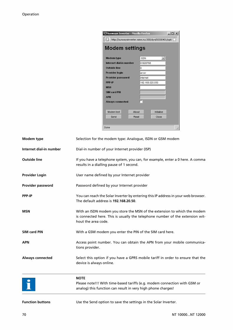
Operation
Modem type Selection for the modem type: Analogue, ISDN or GSM modem
Internet dial-in number Dial-in number of your Internet provider (ISP)
Outside line If you have a telephone system, you can, for example, enter a 0 here. A commaresults in a dialling pause of 1 second.
Provider Login User name defined by your Internet provider
Provider password Password defined by your Internet provider
PPP-IP You can reach the Solar Inverter by entering this IP address in your web browser.The default address is 192.168.20.50.
MSN With an ISDN modem you store the MSN of the extension to which the modemis connected here. This is usually the telephone number of the extension wit-hout the area code.
SIM card PIN With a GSM modem you enter the PIN of the SIM card here.
APN Access point number. You can obtain the APN from your mobile communica-tions provider.
Always connected Select this option if you have a GPRS mobile tariff in order to ensure that thedevice is always online.
NOTEPlease note!!! With time-based tariffs (e.g. modem connection with GSM or analog) this function can result in very high phone charges!
Function buttons Use the Send option to save the settings in the Solar Inverter.
70 NT 10000...NT 12000

Operation
Use Read to display the settings currently stored in the Solar Inverter.
With Modem Test you can test the modem connection to the set Internet provi-der. You will receive feedback as to whether dialling in was successful.
Click About to obtain additional information about the modem.
Click Initialise to re-initialise the modem.
NOTE
Before conducting the modem test, the settings must be stored in the Solar Inverter with Send.
For example, you can select inexpensive dial-in numbers for Internet provi-ders at www.teltarif.de/internet or www.billiger-surfen.de. Here you will find not only tariff information, but also the access data (phone number, user name, password).
E-mail settings In order for the Solar Inverter to be able to send e-mails, the e-mail settingsmust be stored via the Sunways Browser. The settings can be accessed via Set-tings – Network in section E-mail Settings.
NOTERequirements:
When dialling in via modem, the correct dial-up settings must be stored (see Internet dial-up via modem).
SMTP provider SMTP server for sending e-mails, e.g. mail.gmx.net (max. 30 characters). Alter-natively an IP address can be entered.
SMTP user User name for your e-mail provider (generally your e-mail address), e.g. [email protected] (max. 50 characters)
SMTP password Password for your e-mail provider (max. 20 characters)
Function buttons Via SMTP Test you can send a test message to the e-mail address stored for ac-tive alerting.
NOTE
Before conducting the SMTP test, the settings must be stored in the Solar In-verter with Send.
NT 10000...NT 12000 71
Operation
During the SMTP tests an e-mail is sent to the e-mail address stored in the sys-tem monitoring unit (active alerting). Before starting the test check whether a valid e-mail address is stored under active alerting.
If no login is set up on the configured SMTP server, the password field must be left empty. The login field is entered as the sender address for the e-mail. If no login is specified, the Solar Inverter sends the e-mail as [email protected].
Use the Send option to save the settings in the Solar Inverter.
Use Read to display the settings currently stored in the Solar Inverter.
Active alerting
General information With active alerting you can receive) status messages (errors and warnings) foryour solar system by e-mail. If a status message was active for longer than 15 mi-nutes or occurred 5 times in one day, you will receive an e-mail at the next fullhour, which is sent to the e-mail address stored in the Solar Inverter.
NOTEThe main unit sends the status messages of all Solar Inverters if they are CAN-networked.
Requirements:
The main unit must be connected to the Internet via a network or modem.
When dialling in via modem, the correct dial-up settings must be stored (see Internet dial-up via modem).
Correct e-mail settings must be stored in the Sunways Browser (see E-mail settings).
Alerting settings The alerting settings can be accessed with the button Settings – System Monito-ring in the Active Alerting section.
72 NT 10000...NT 12000

Operation
Active e-mail alerting Activation or deactivation of the active alerting function.
E-mail address In the E-mail address field you enter the e-mail address to which the messagesare to be sent.
Function buttons Use the Send option to save the settings in the Solar Inverter.
Use Read to display the settings currently stored in the Solar Inverter.
Sunways portal connection
General information You can have the operating data of your solar system automatically sent to theSunways Portal to monitor your system via the Internet. This is possible withoutusing a Sunways Communicator.
The portal connection is configured via the Sunways Browser. Following activa-tion the main unit automatically sends a registration e-mail containing the sys-tem data (e.g. number of units, serial number, etc.) to the Sunways Portal.
After activation the operating data for each day are sent to the Sunways Portalby e-mail on a daily basis before the main unit is switched off for the night. Theinterval can also be set shorter as an alternative. If a change is made to your so-lar system (e.g. additional unit), then the change is automatically reported tothe Sunways Portal.
A basis access for the Sunways Portal for displaying the yield data is available toevery Sunways customer free of charge. Expanded functions, e.g. the set-point-actual comparison in the Sunways Portal, can also be purchased for a fee.
NOTEThe main unit sends the status messages of all Solar Inverters if they are CAN-networked.
Requirements:
NT 10000...NT 12000 73

Operation
The main unit must be connected to the Internet via a network or modem.
Correct e-mail settings must be stored in the Sunways Browser (see E-mail settings)
Correct portal settings must be stored in the Sunways Browser.
Setup Check whether you meet all requirements. Configure the specified settings ifnecessary.
Open the setting page in the Sunways Browser. This can be accessed under Set-tings – System Monitoring in the section Sunways Portal.
Portal connection Activation or deactivation of the portal connection.
Portal address Preset for the Sunways Portal
Mailbox file Preset for the Sunways Portal
System ID System ID assigned by the portal. This is generated automatically after portal ac-tivation and sent to the Solar Inverter. It can take up to 4 minutes before theSolar Inverter displays the system ID.
Portal E-mail Preset for the Sunways Portal. Here as well, you can enter another address if youwant to evaluate the operating data yourself.
E-mail interval Select the interval at which the e-mails are to be sent. If you operate the systemon a DSL modem, you can set a short interval. If you use a modem connection,select a longer interval (e.g. daily) to eliminate unnecessary phone charges).
User E-mail Enter an e-mail address in this field, to which the confirmation message will besent by the Portal. It contains a link for the activation of your system in the Sun-ways Portal.
User SMS As an option you can specify a mobile number to which a text message is sentonce your system is successfully set up in the Portal.
74 NT 10000...NT 12000

Operation
Function buttons Use Portal Test to test the portal connection. You will receive an e-mail at theaddress specified under User E-mail and text message if you have entered yourmobile phone number in under User SMS.
NOTEBefore the portal test you must transfer the settings to your Solar Inverter with Send. In addition, an SMTP server must be configured. These settings can be changed under Networking. If the test was successful, a an e-mail is sent to the user e-mail address or a text message to the specified phone number.
Use the Send option to save the settings in the Solar Inverter.
To view your system data in the Sunways Portal you need a user account. Thiswill be issued to you if you follow the link in the confirmation e-mail and fill outthe registration form.
As an alternative you can also enter an existing user name with the correct pass-word to assign the system to an existing user account.
NT 10000...NT 12000 75

Operation
76 NT 10000...NT 12000

A Appendix
A.1 Drilling template for the wall bracket
You can use the following template for installing the wall bracket. The templateshows all distances and dimensions.
A.2 General liability disclaimer
Although information contained in this manual has been checked with the gre-atest care for its accuracy and completeness, not liability whatsoever can be ac-cepted for errors or omissions.
Sunways AG reserves the right to change the hardware and software fea-tures described here at any time without prior notice.
This manual may not be reproduced, passed on, copied or translated into other languages in whole or in part in any form or with any means without prior written approval by Sunways AG.
Sunways AG shall assume no guarantee for damage caused by faulty or lost data, due to incorrect operation or the malfunction of the Solar Inverter, the software, additional devices or PCs.
All rights reserved. © Sunways AG
The products named on cover page are protected by copyright and sold underlicence. No part of this document may be reproduced in any form without priorwritten approval of Sunways AG and the Sunways licensors.
Registered trademark The Sunways logo is a registered trademark of Sunways AG, Konstanz.
HERIC® is a registered trademark of Fraunhofer Gesellschaft, Munich.
470
10 10
12
10,50
R5,25
100
NT 10000...NT 12000 77

78 NT 10000...NT 12000

NT 10000...NT 12000 79

SD13
0912
A 0
8/10
EN
Sunways AG Photovoltaic Technology Macairestraße 3 - 5 D - 78467 Konstanz Phone +49 (0)7531 996 77 -0 Fax +49 (0)7531 996 77 -444 E-Mail [email protected] www.sunways.de
Technical HotlineGermany: +49 (0)7531 996 77-577Spain: +34 93 665 20-40