manual tech x flex base issue1 - fcc id search€¦ · spirent communications ... • unit - a...
TRANSCRIPT

Tech-X Flex™
Base Unit User Guide

Spirent Communications20324 Seneca Meadows ParkwayGermantown, MD 20876 USA
+1 301.444.2400800.385.0110 (USA only)
www.spirent.com

Tech-X Flex™ Base Unit User Guide Issue 1
-i
Contents
1: Introduction1.1 Documentation notes . . . . . . . . . . . . . . . . . . . . . . . . . . . . . . . . . . . . . . . . . . . 1-1
1.1.1 Document purpose and scope . . . . . . . . . . . . . . . . . . . . . . . . . . . . . . . . . . . . . . . . . . 1-11.1.2 Definitions of terms and acronyms . . . . . . . . . . . . . . . . . . . . . . . . . . . . . . . . . . . . . . 1-11.1.3 Additional documentation . . . . . . . . . . . . . . . . . . . . . . . . . . . . . . . . . . . . . . . . . . . . . 1-2
1.2 Product introduction . . . . . . . . . . . . . . . . . . . . . . . . . . . . . . . . . . . . . . . . . . . 1-21.2.1 Product purpose . . . . . . . . . . . . . . . . . . . . . . . . . . . . . . . . . . . . . . . . . . . . . . . . . . . . 1-21.2.2 User prerequisites . . . . . . . . . . . . . . . . . . . . . . . . . . . . . . . . . . . . . . . . . . . . . . . . . . . 1-31.2.3 Base unit features . . . . . . . . . . . . . . . . . . . . . . . . . . . . . . . . . . . . . . . . . . . . . . . . . . . 1-31.2.4 Front panel controls . . . . . . . . . . . . . . . . . . . . . . . . . . . . . . . . . . . . . . . . . . . . . . . . . . 1-41.2.5 LED indicators . . . . . . . . . . . . . . . . . . . . . . . . . . . . . . . . . . . . . . . . . . . . . . . . . . . . . . 1-61.2.6 Base unit physical interfaces (ports) . . . . . . . . . . . . . . . . . . . . . . . . . . . . . . . . . . . . . 1-8
1.3 General product handling and operation . . . . . . . . . . . . . . . . . . . . . . . . . . . 1-91.3.1 Powering on/off and sleep mode . . . . . . . . . . . . . . . . . . . . . . . . . . . . . . . . . . . . . . . . 1-91.3.2 Attaching, detaching, and handling modules . . . . . . . . . . . . . . . . . . . . . . . . . . . . . . . 1-91.3.3 Attaching the Wi-Fi antenna . . . . . . . . . . . . . . . . . . . . . . . . . . . . . . . . . . . . . . . . . . 1-101.3.4 Attaching the strap . . . . . . . . . . . . . . . . . . . . . . . . . . . . . . . . . . . . . . . . . . . . . . . . . . 1-111.3.5 About the touchscreen display . . . . . . . . . . . . . . . . . . . . . . . . . . . . . . . . . . . . . . . . 1-131.3.6 Selecting the active interface . . . . . . . . . . . . . . . . . . . . . . . . . . . . . . . . . . . . . . . . . . 1-131.3.7 Starting a function or test . . . . . . . . . . . . . . . . . . . . . . . . . . . . . . . . . . . . . . . . . . . . . 1-131.3.8 Stopping a test . . . . . . . . . . . . . . . . . . . . . . . . . . . . . . . . . . . . . . . . . . . . . . . . . . . . . 1-151.3.9 Saving results . . . . . . . . . . . . . . . . . . . . . . . . . . . . . . . . . . . . . . . . . . . . . . . . . . . . . 1-151.3.10 Interpreting results . . . . . . . . . . . . . . . . . . . . . . . . . . . . . . . . . . . . . . . . . . . . . . . . . 1-15
1.4 Maintenance . . . . . . . . . . . . . . . . . . . . . . . . . . . . . . . . . . . . . . . . . . . . . . . . . 1-151.4.1 Battery replacement . . . . . . . . . . . . . . . . . . . . . . . . . . . . . . . . . . . . . . . . . . . . . . . . 1-16

Base Unit User Guide Issue 1 Tech-X Flex™
-ii
IntroW
i-Fi10/100
SystemIP/Video
Specs
1.5 Technical support . . . . . . . . . . . . . . . . . . . . . . . . . . . . . . . . . . . . . . . . . . . . . 1-17
2: Wi-Fi Testing Menu2.1 Functionality note . . . . . . . . . . . . . . . . . . . . . . . . . . . . . . . . . . . . . . . . . . . . . . 2-22.2 Wi-Fi overview . . . . . . . . . . . . . . . . . . . . . . . . . . . . . . . . . . . . . . . . . . . . . . . . . 2-2
2.2.1 Wi-Fi support details . . . . . . . . . . . . . . . . . . . . . . . . . . . . . . . . . . . . . . . . . . . . . . . . .2-22.2.2 Wi-Fi testing diagram . . . . . . . . . . . . . . . . . . . . . . . . . . . . . . . . . . . . . . . . . . . . . . . . .2-22.2.3 If you cannot connect (troubleshooting tips) . . . . . . . . . . . . . . . . . . . . . . . . . . . . . . .2-32.2.4 About the connection history and “auto-connect” networks . . . . . . . . . . . . . . . . . . . .2-4
2.3 Wi-Fi Setup. . . . . . . . . . . . . . . . . . . . . . . . . . . . . . . . . . . . . . . . . . . . . . . . . . . . 2-52.3.1 Wi-Fi Setup > Scan . . . . . . . . . . . . . . . . . . . . . . . . . . . . . . . . . . . . . . . . . . . . . . . . . .2-5
Setup - Scan (Wi-Fi Setup) . . . . . . . . . . . . . . . . . . . . . . . . . . . . . . . . . . . . . . . . . . . . . . .2-6Results - Scan (Wi-Fi Setup) . . . . . . . . . . . . . . . . . . . . . . . . . . . . . . . . . . . . . . . . . . . . .2-6
2.3.2 Wi-Fi Setup > Connect . . . . . . . . . . . . . . . . . . . . . . . . . . . . . . . . . . . . . . . . . . . . . . . .2-6Setup - Connect (Wi-Fi Setup) . . . . . . . . . . . . . . . . . . . . . . . . . . . . . . . . . . . . . . . . . . . .2-7Results - Connect (Wi-Fi Setup) . . . . . . . . . . . . . . . . . . . . . . . . . . . . . . . . . . . . . . . . . . .2-9
2.3.3 Wi-Fi Setup > Details . . . . . . . . . . . . . . . . . . . . . . . . . . . . . . . . . . . . . . . . . . . . . . . . .2-92.3.4 Wi-Fi Setup > View Auto-Connect Networks . . . . . . . . . . . . . . . . . . . . . . . . . . . . . .2-10
2.4 IP Network Setup . . . . . . . . . . . . . . . . . . . . . . . . . . . . . . . . . . . . . . . . . . . . . . 2-102.5 Ping. . . . . . . . . . . . . . . . . . . . . . . . . . . . . . . . . . . . . . . . . . . . . . . . . . . . . . . . . 2-102.6 Traceroute . . . . . . . . . . . . . . . . . . . . . . . . . . . . . . . . . . . . . . . . . . . . . . . . . . . 2-112.7 Web Browser . . . . . . . . . . . . . . . . . . . . . . . . . . . . . . . . . . . . . . . . . . . . . . . . . 2-11
3: 10/100 Testing Menu3.1 Functionality note . . . . . . . . . . . . . . . . . . . . . . . . . . . . . . . . . . . . . . . . . . . . . . 3-23.2 About the 10/100 ports and connections . . . . . . . . . . . . . . . . . . . . . . . . . . . 3-23.3 10/100 testing diagram . . . . . . . . . . . . . . . . . . . . . . . . . . . . . . . . . . . . . . . . . . 3-23.4 IP Network Setup . . . . . . . . . . . . . . . . . . . . . . . . . . . . . . . . . . . . . . . . . . . . . . . 3-33.5 Ping. . . . . . . . . . . . . . . . . . . . . . . . . . . . . . . . . . . . . . . . . . . . . . . . . . . . . . . . . . 3-33.6 Traceroute . . . . . . . . . . . . . . . . . . . . . . . . . . . . . . . . . . . . . . . . . . . . . . . . . . . . 3-33.7 Web Browser . . . . . . . . . . . . . . . . . . . . . . . . . . . . . . . . . . . . . . . . . . . . . . . . . . 3-33.8 IP Video Tests . . . . . . . . . . . . . . . . . . . . . . . . . . . . . . . . . . . . . . . . . . . . . . . . . 3-3

Tech-X Flex™ Base Unit User Guide Issue 1
-iii
Intr
oW
i-Fi
10/1
00Sy
stem
IP/V
ideo
Spec
s
3.9 Passive testing . . . . . . . . . . . . . . . . . . . . . . . . . . . . . . . . . . . . . . . . . . . . . . . . 3-43.9.1 Unit setup for passive testing . . . . . . . . . . . . . . . . . . . . . . . . . . . . . . . . . . . . . . . . . . 3-43.9.2 Passive Video Quality of Service (QoS) . . . . . . . . . . . . . . . . . . . . . . . . . . . . . . . . . . 3-5
4: System Menu4.1 Record Manager . . . . . . . . . . . . . . . . . . . . . . . . . . . . . . . . . . . . . . . . . . . . . . . 4-14.2 10/100 Admin Port. . . . . . . . . . . . . . . . . . . . . . . . . . . . . . . . . . . . . . . . . . . . . . 4-24.3 Set Date and Time. . . . . . . . . . . . . . . . . . . . . . . . . . . . . . . . . . . . . . . . . . . . . . 4-34.4 Auto Sleep Mode. . . . . . . . . . . . . . . . . . . . . . . . . . . . . . . . . . . . . . . . . . . . . . . 4-44.5 Version Info . . . . . . . . . . . . . . . . . . . . . . . . . . . . . . . . . . . . . . . . . . . . . . . . . . . 4-44.6 Battery Status . . . . . . . . . . . . . . . . . . . . . . . . . . . . . . . . . . . . . . . . . . . . . . . . . 4-44.7 Channel Guide/Network Setup . . . . . . . . . . . . . . . . . . . . . . . . . . . . . . . . . . . 4-5
4.7.1 About channel guides . . . . . . . . . . . . . . . . . . . . . . . . . . . . . . . . . . . . . . . . . . . . . . . . 4-74.7.2 Importing channel guides to the unit . . . . . . . . . . . . . . . . . . . . . . . . . . . . . . . . . . . . . 4-7
4.8 Download Channel Guide . . . . . . . . . . . . . . . . . . . . . . . . . . . . . . . . . . . . . . . 4-94.9 Wireless ON/OFF. . . . . . . . . . . . . . . . . . . . . . . . . . . . . . . . . . . . . . . . . . . . . . . 4-94.10 Calibrate Touchscreen . . . . . . . . . . . . . . . . . . . . . . . . . . . . . . . . . . . . . . . . 4-104.11 Licensed Options . . . . . . . . . . . . . . . . . . . . . . . . . . . . . . . . . . . . . . . . . . . . 4-104.12 Update Firmware. . . . . . . . . . . . . . . . . . . . . . . . . . . . . . . . . . . . . . . . . . . . . 4-10
5: IP and Video Testing5.1 IP Network Setup . . . . . . . . . . . . . . . . . . . . . . . . . . . . . . . . . . . . . . . . . . . . . . 5-1
5.1.1 Setup - IP Network Setup . . . . . . . . . . . . . . . . . . . . . . . . . . . . . . . . . . . . . . . . . . . . . 5-25.1.2 Results - IP Network Setup . . . . . . . . . . . . . . . . . . . . . . . . . . . . . . . . . . . . . . . . . . . . 5-3
5.2 Connection Information . . . . . . . . . . . . . . . . . . . . . . . . . . . . . . . . . . . . . . . . . 5-35.3 Ping . . . . . . . . . . . . . . . . . . . . . . . . . . . . . . . . . . . . . . . . . . . . . . . . . . . . . . . . . 5-4
5.3.1 Setup - Ping . . . . . . . . . . . . . . . . . . . . . . . . . . . . . . . . . . . . . . . . . . . . . . . . . . . . . . . . 5-45.3.2 Results - Ping . . . . . . . . . . . . . . . . . . . . . . . . . . . . . . . . . . . . . . . . . . . . . . . . . . . . . . 5-4
5.4 Traceroute . . . . . . . . . . . . . . . . . . . . . . . . . . . . . . . . . . . . . . . . . . . . . . . . . . . . 5-55.4.1 Setup - Traceroute test . . . . . . . . . . . . . . . . . . . . . . . . . . . . . . . . . . . . . . . . . . . . . . . 5-55.4.2 Results - Traceroute test . . . . . . . . . . . . . . . . . . . . . . . . . . . . . . . . . . . . . . . . . . . . . . 5-6

Base Unit User Guide Issue 1 Tech-X Flex™
-iv
IntroW
i-Fi10/100
SystemIP/Video
Specs
5.5 Web Browser . . . . . . . . . . . . . . . . . . . . . . . . . . . . . . . . . . . . . . . . . . . . . . . . . . 5-65.5.1 Setup - Web Browser . . . . . . . . . . . . . . . . . . . . . . . . . . . . . . . . . . . . . . . . . . . . . . . . .5-7
5.6 IP Video testing . . . . . . . . . . . . . . . . . . . . . . . . . . . . . . . . . . . . . . . . . . . . . . . . 5-75.6.1 Video Quality of Service (QoS) . . . . . . . . . . . . . . . . . . . . . . . . . . . . . . . . . . . . . . . . .5-8
Setup - Video Quality of Service . . . . . . . . . . . . . . . . . . . . . . . . . . . . . . . . . . . . . . . . . . .5-8Results - Video Quality of Service (VQM test) . . . . . . . . . . . . . . . . . . . . . . . . . . . . . . .5-14Digital video concepts overview . . . . . . . . . . . . . . . . . . . . . . . . . . . . . . . . . . . . . . . . . .5-20
About basic video and audio compression . . . . . . . . . . . . . . . . . . . . . . . . . . . . . . . 5-20About MPEG transport . . . . . . . . . . . . . . . . . . . . . . . . . . . . . . . . . . . . . . . . . . . . . . 5-23About IP multicast . . . . . . . . . . . . . . . . . . . . . . . . . . . . . . . . . . . . . . . . . . . . . . . . . 5-25
Quality measurement overview and additional results descriptions . . . . . . . . . . . . . . .5-27How the analysis works - An overview . . . . . . . . . . . . . . . . . . . . . . . . . . . . . . . . . . 5-27About MOS . . . . . . . . . . . . . . . . . . . . . . . . . . . . . . . . . . . . . . . . . . . . . . . . . . . . . . . 5-28About gap and burst states . . . . . . . . . . . . . . . . . . . . . . . . . . . . . . . . . . . . . . . . . . 5-29Other test results . . . . . . . . . . . . . . . . . . . . . . . . . . . . . . . . . . . . . . . . . . . . . . . . . . 5-29
Additional video testing notes . . . . . . . . . . . . . . . . . . . . . . . . . . . . . . . . . . . . . . . . . . . .5-30About the IP address specified for testing . . . . . . . . . . . . . . . . . . . . . . . . . . . . . . . 5-30About encrypted (scrambled) signals and frame type recognition . . . . . . . . . . . . . 5-30
5.6.2 Channel Change Time . . . . . . . . . . . . . . . . . . . . . . . . . . . . . . . . . . . . . . . . . . . . . . .5-30Setup - Channel Change Time . . . . . . . . . . . . . . . . . . . . . . . . . . . . . . . . . . . . . . . . . . .5-31Results - Channel Change Time . . . . . . . . . . . . . . . . . . . . . . . . . . . . . . . . . . . . . . . . . .5-32How channel change time is calculated . . . . . . . . . . . . . . . . . . . . . . . . . . . . . . . . . . . .5-32
6: Specifications6.1 General specifications . . . . . . . . . . . . . . . . . . . . . . . . . . . . . . . . . . . . . . . . . . 6-16.2 Wi-Fi specifications . . . . . . . . . . . . . . . . . . . . . . . . . . . . . . . . . . . . . . . . . . . . . 6-26.3 FCC compliance statements. . . . . . . . . . . . . . . . . . . . . . . . . . . . . . . . . . . . . . 6-3

Tech-X Flex™ Base Unit User Guide Issue 1
1: Introduction 1-1
1: Introduction
This section provides an overview of the Tech-X Flex product and includes the following information:
• Documentation notes on page 1-1 - Describes this document and the terminology within.
• Product introduction on page 1-2 - Describes the physical unit and includes a high-level overview of system features and capabilities.
• General product handling and operation on page 1-9 - Describes basic procedures for handling and operating the unit.
• Maintenance on page 1-15 - Describes maintenance requirements and procedures for the unit.
• Technical support on page 1-17 - Provides contact information.
1.1 Documentation notes
1.1.1 Document purpose and scopeThis document is intended for field technicians and other personnel who use the product for circuit and network testing. Depending upon your licensing agreement, your unit may not include all the functionality presented in this document. For more information about licensing arrangements, please contact a Spirent account manager.
1.1.2 Definitions of terms and acronymsFor clarity, the following terms are defined:

Base Unit User Guide Issue 1 Tech-X Flex™
1-2 1: Introduction
IntroW
i-Fi10/100
SystemIP/Video
Specs
• Unit - A Tech-X Flex device in general, with or without a module attached, as applicable to the respective context.
• Base Unit - The core handheld component to which modules attach. The base unit has an independent suite of functionality which is described in this document. The use of modules does not change base unit functionality.
• Module - A modular hardware component designed to attach and interface with the Tech-X Flex base unit that provides additional functionality. Documentation for modules is provided separately from this document.
• Provider - A broadband service provider, such as a telephone or cable company.
• Subscriber - A customer receiving broadband services from a provider.
Additionally, note the following common acronyms:
• FTTH/FTTP - Fiber To The Home/Fiber To The Premises
• IP - Internet Protocol
• IPTV - IP Television
• LAN - Local Area Network
• MoCA® - Multimedia over Coax Alliance
• STB - Set-Top Box
• WAN - Wide Area Network
1.1.3 Additional documentationAdditional documentation (including an electronic version of this document) can be found on Spirent’s Customer Service Network. Support requests and training information are also available on the site. Use the URL below to register and gain access:
http://assure.spirentcom.com/extranet/
1.2 Product introductionThe following sections provide a high-level overview of the unit.
1.2.1 Product purposeThe unit is designed to assist with the setup and troubleshooting of home networks, especially as related to broadband services delivered by high-speed DSL, cable, and fiber-to-the-premises (FTTP)

Tech-X Flex™ Base Unit User Guide Issue 1
1: Introduction 1-3
Intr
oW
i-Fi
10/1
00Sy
stem
IP/V
ideo
Spec
s
architectures. It serves as a small and versatile in-home tester for technicians who are increasingly required to troubleshoot networking issues from within the home, including the isolation of trouble to the provider or subscriber sides of the network.
Primarily, the unit is able to emulate various devices within a home network and perform testing to sectionalize problems. For example, if a subscriber cannot access the internet, the unit can emulate a home computer and verify whether ISP connectivity is actually available. The unit can also perform a variety of other connectivity-related and statistics-gathering functions. Using detachable modules, the unit can be expanded to support different types of protocols and devices, such as the MoCA module which provides an interface for in-home MoCA network testing.
1.2.2 User prerequisitesTo use the unit and this documentation effectively, you should have some knowledge of network architectures, especially Ethernet-based networks typically found in the home. While this document attempts to explain unit functionality in reasonable detail, it cannot substitute for a basic understanding of networking principles. If you are new to networking and related technologies, consider additional training before attempting to use the unit and/or understand this document.
1.2.3 Base unit features
NOTE: Your unit may or may not include all of the features described here, dependent upon your licensing agreement with Spirent. Please contact Spirent for more information.

Base Unit User Guide Issue 1 Tech-X Flex™
1-4 1: Introduction
IntroW
i-Fi10/100
SystemIP/Video
Specs
• Ethernet and IP connectivity testing - With its 10/100 interface, the unit can link to an Ethernet network at any standard transport device such as a home router, hub, or Ethernet switch. Once linked, the unit can join an IP network and perform testing such as ping, traceroute, and internet webpage access. These abilities make the unit ideal for verifying connectivity within the home and isolating problems to either the provider or subscriber networks.
• Wi-Fi testing - The unit includes a Wi-Fi interface that can sync with wireless devices using 802.11b, including support for WEP security. Similar to Ethernet testing, the Wi-Fi interface allows you to join a wireless network and perform IP-based testing to verify connectivity and sectionalize issues.
• IP video analysis - The unit is able to join a video stream and measure video quality and channel change time. In this fashion, it can emulate a set-top box (STB) and provide a comprehensive evaluation of IPTV quality. It can also bridge an existing stream on a link for passive monitoring. For example, it can be placed between a home router and a real STB to passively monitor the video communications between the devices, even while the video is simultaneously displaying on a TV.
• Expansion of features with modular hardware - The unit is designed for expansion by attaching feature-specific modules, such as the MoCA module for testing of home MoCA networks. For more information on available modules, please contact Spirent. For more information on the operation of any specific module, see the documentation for that module.
1.2.4 Front panel controls

Tech-X Flex™ Base Unit User Guide Issue 1
1: Introduction 1-5
Intr
oW
i-Fi
10/1
00Sy
stem
IP/V
ideo
Spec
sFigure 1-1 Front panel controls
F1 F2 F3 F4
SYNC DATA CHARGEERRORS
Tech-X Flex
5: Battery Status
1: 10/100 Admin Port2: Set Date and Time3: Auto Sleep Mode4: Version Info
6: Channel Guide/Network Setup7: Download Channel Guide8: Wireless ON/OFF
0: Record ManagerBack
MoCA Wi-Fi 10/100 System
ENTER
EXIT
1 2ABC
3DEF
5JKL
6MNO
4GHI
8TUV
9WXYZ
7PQRS
0 HELPN1
Wi-Fi antenna
Touchscreen display
Power on/off LED indicators
Function keys
Arrow keys
Alphanumeric keypad
Enter
Exit
Backlight
Help
N1
Strap mount
[System]

Base Unit User Guide Issue 1 Tech-X Flex™
1-6 1: Introduction
IntroW
i-Fi10/100
SystemIP/Video
Specs
1.2.5 LED indicators
Table 1-1 Front panel feature descriptions
Indicator Function
Power on/off Powers the unit on and off, and is also used to place the unit into sleep mode (see Powering on/off and sleep mode on page 1-9).
LED indicators See LED indicators on page 1-6.
Strap mount See Attaching the strap on page 1-11.
Wi-Fi antenna See Attaching the Wi-Fi antenna on page 1-10.
Enter Engages the active control on the screen, such as a button or a text entry box.
Exit Halts the current action or test, often returning the display to the previous screen.
Backlight Adjusts the brightness of the display backlight.
Help Used as a backspace on the text entry pad. Future versions will include onscreen help launched with this button.
N1 Used to enter special characters on the text entry pad, such as periods.
Function keys Used to select the active test interface and/or functional area, such as the Wi-Fi interface or the System configuration menu.
Arrow keys Provide navigational control over numerous display items, such as scroll bars, multi-item lists, parameter entry screen controls, tabs, and more.
Alphanumeric keypad
Used for text entry.
SYNC DATA CHARGEERRORS
Tech-X Flex

Tech-X Flex™ Base Unit User Guide Issue 1
1: Introduction 1-7
Intr
oW
i-Fi
10/1
00Sy
stem
IP/V
ideo
Spec
s
Table 1-2 LED indicator description
Indicator Function
SYNC Indicates the status of the link over the active interface. For example, when using the Wi-Fi interface, the LED indicates the status of the Wi-Fi link. The general behavior is as follows:• Solid green - The unit is properly linked and/or synchronized with a comparable far-
end device. For the 10/100 interface, the LED is solid green any time the interface is configured with IP information, but does not necessarily indicate that the information is valid and routable.
• Red - The unit is attempting to configure the active interface and/or link with a far-end device.
DATA Flashes when sending or receiving data over the active interface. For example, when using the 10/100 interface, the LED flashes when an Ethernet frame is sent or received.
ERRORS Indicates errors at the data link level on the active data stream. For example, on the 10/100 interface, the LED may indicate Ethernet frame CRC errors.
CHARGE Indicates power source and charging status, as follows:• Solid red - Unit is connected to an external power source and the battery is charging• Solid green - Unit is connected to an external power source and the battery is nearly
or fully charged• Off - Unit is not connect to external power (unit on or off) and/or the unit has no battery
installedNote that the unit includes a system feature for reporting detailed information about battery status. For more information, see Battery Status on page 4-4.

Base Unit User Guide Issue 1 Tech-X Flex™
1-8 1: Introduction
IntroW
i-Fi10/100
SystemIP/Video
Specs
1.2.6 Base unit physical interfaces (ports)
Figure 1-2 Base unit right side
Figure 1-3 Base unit left side
Note the following:
Ethernet (10/100) port 1
1 - 2
Ethernet (10/100) port 2
Mic/headset jack
12V
AC power/chargeUSB port
2A

Tech-X Flex™ Base Unit User Guide Issue 1
1: Introduction 1-9
Intr
oW
i-Fi
10/1
00Sy
stem
IP/V
ideo
Spec
s
• Modules have their own physical interfaces. See the documentation for the respective module for more information.
• The two Ethernet interfaces are used for 10/100 testing and for administrative functions on the unit, such as upgrading firmware.
• The 2.5 mm mic/headset jack and USB port are for future use.
1.3 General product handling and operationThis section provides basic information for general operation. For most functions and tests, the buttons, display, and other components operate in a similar fashion. Once you become familiar with general operation, you should be able to set up and run most functions and tests, referring to this document only as necessary for specific technical details, contained elsewhere in this document.
1.3.1 Powering on/off and sleep modeWhen the unit is off, the power button turns it on. When the unit is on, the power button prompts you whether to power off the unit or to place it into sleep mode. Sleep mode allows the unit to save power but return to active testing more quickly than a full boot up. To restore the unit from sleep mode, press the power button once again. Note that the restoration process causes the unit to recheck module and licensing status, after which it returns the screen to the default menu, not necessarily the menu that was active when sleep mode was activated.
The unit supports automatic sleep mode activation after a specified amount of idle time. For more information, see Auto Sleep Mode on page 4-4.
1.3.2 Attaching, detaching, and handling modules
CAUTION: Before attaching or detaching a module, the unit must be powered off or placed into sleep mode. Failure to do this could result in damage to the module or base unit firmware. For more information on initiating sleep mode, see Powering on/off and sleep mode on page 1-9.
NOTE: To prevent damage to the module bay and to keep electrical connections clean, you should keep the module placeholder (the “dummy” module) installed when no module is in use. New units are shipped with the placeholder attached.
Modules are fastened to the base unit using fastener screws attached to the upper “feet” of the unit. To remove a module, loosen/disengage the two screws and gently pull the module from its electrical

Base Unit User Guide Issue 1 Tech-X Flex™
1-10 1: Introduction
IntroW
i-Fi10/100
SystemIP/Video
Specs
connection. Likewise, to attach a module, gently press the module into the base unit to seat the electrical connection, then finger-tighten the screws.
Figure 1-4 Rear of unit with a module installed, showing the fastener screws
Once a module is attached and has booted up, a menu corresponding to the module functionality will appear over the F1 function key. For example, when the MoCA module is attached, the F1 menu shows “MoCA.” If no module is attached, the F1 key shows no menu.
1.3.3 Attaching the Wi-Fi antennaThe antenna should be attached before using the Wi-Fi interface. The base of the antenna screws onto the unit by hand. Note that the process is easier if the antenna is straightened while attaching and detaching:
Module
Fastener screws

Tech-X Flex™ Base Unit User Guide Issue 1
1: Introduction 1-11
Intr
oW
i-Fi
10/1
00Sy
stem
IP/V
ideo
Spec
s
Figure 1-5 Attaching the antenna
Figure 1-6 Antenna positioned for typical use, following attachment
1.3.4 Attaching the strapA strap with a hook is provided to hang the unit while working. To attach the strap, first make sure that the buckle is facing up, then slide the open end around and through the strap mount at the top of the unit:
CHARGE
CHARGE

Base Unit User Guide Issue 1 Tech-X Flex™
1-12 1: Introduction
IntroW
i-Fi10/100
SystemIP/Video
Specs
Figure 1-7 Sliding the open strap end through the strap mount
Next, feed the open end through the bottom of the buckle as shown in the following figure:
Figure 1-8 Feeding the strap through the buckle
SYNC DATA CHARGEERRORS
Tech-X Flex
(To hook)
Strap end
2
Strap end
(To hook)Buckle

Tech-X Flex™ Base Unit User Guide Issue 1
1: Introduction 1-13
Intr
oW
i-Fi
10/1
00Sy
stem
IP/V
ideo
Spec
s
1.3.5 About the touchscreen displayThe unit display includes touchscreen functionality which allows you to operate most display controls by touching the screen. You should use a plastic stylus or a similar device. It is recommended to avoid using your fingers because it is difficult to control selections with precision.
CAUTION: Never use a sharp or metallic object which will damage the screen. Likewise, do not use a ballpoint pen, pencil, or any other writing device which will mar the screen.
For new units, units with new firmware, or units with a new battery, a calibration of the touchscreen should be performed. For more information, see Calibrate Touchscreen on page 4-10.
1.3.6 Selecting the active interfaceWhile testing with the unit, the first step is to select the appropriate interface with one of the function keys, such as the 10/100 or Wi-Fi interface, or perhaps another interface associated with an attached module. The interface and any associated hardware remain active only while testing in the respective area continues. If you switch to a different interface, the previous interface shuts down and loses its IP configuration, if any. For example, if you switch from the Wi-Fi interface to the 10/100 interface, the Wi-Fi interface will shut down and any IP configuration will be lost.
An exception exists with the Wi-Fi interface, which can be optionally configured to remain active all the time. For more information, see Wireless ON/OFF on page 4-9.
1.3.7 Starting a function or testTo run any function or test, the following steps generally apply:

Base Unit User Guide Issue 1 Tech-X Flex™
1-14 1: Introduction
IntroW
i-Fi10/100
SystemIP/Video
Specs
1. Using the function keys or the touchscreen, select the correct menu/interface.
2. Using the up/down arrows, number pad, and/or touchscreen, select the desired menu item and possibly submenu items to activate the desired function/test.
3. For tests that require input parameters, adjust those parameters as necessary, using the navigation arrows and/or touchscreen. For free-form text entries, place the cursor in the field and press any number key to produce the text entry window:
Using the touchscreen and/or the number keys, enter the desired data. Note the following:
F1 F2 F3 F4
8: Wireless ON/OFF
MoCA Wi-Fi 10/100 System
A function key selects the function/test/menu directly above

Tech-X Flex™ Base Unit User Guide Issue 1
1: Introduction 1-15
Intr
oW
i-Fi
10/1
00Sy
stem
IP/V
ideo
Spec
s
• The text entry pad is similar to a standard text message device, where you must press a key multiple times to cycle through the associated letters. For example, to enter a “b”, press the “2” key three times quickly, then pause.
• The N1 key allows you to enter special characters, such as a period.• The Help button on the physical keypad acts as a backspace.
4. Press the appropriate button to start the respective action, normally “Start” or “OK.”
NOTE: The unit is designed to be controlled by either the keypad or the touchscreen, or a combination of both. You should become familiar with both methods of unit control, because you may find that a combination of the two provides the most efficiency.
1.3.8 Stopping a testTests can be stopped immediately with the EXIT key. Also, the Back button in the upper left corner of the screen normally exits the current test. Some tests may require a small amount of shutdown time before terminating completely.
1.3.9 Saving resultsMost tests allow you to save the results using the Save button on the results screen (F4 key). Results are saved to the active record within the Record Manager. For more information, see Record Manager on page 4-1.
1.3.10 Interpreting resultsIn some cases, this document provides results samples and references to industry standards for pass/fail criteria. None of this information should be construed as a recommendation or mandate on how any given organization should interpret results. In all cases, you should consult local and corporate protocol for the standards by which you interpret results. This document does not intend in any way to serve as an authorized or approved standard for the operation and maintenance of any telecommunications network.
1.4 MaintenanceThe only maintenance task that should be performed by users is battery replacement. For all other maintenance requirements, return the unit to Spirent. Do not remove the cover of the unit during battery replacement or at any other time. For more information on battery replacement, see Battery replacement on page 1-16.

Base Unit User Guide Issue 1 Tech-X Flex™
1-16 1: Introduction
IntroW
i-Fi10/100
SystemIP/Video
Specs
1.4.1 Battery replacementUsers may perform field replacement of the battery pack. Note the following:
• New battery packs should be ordered from Spirent.
• Batteries contain hazardous contaminants and should be disposed of according to local regulations. It may be illegal to discard batteries in the general trash.
To replace the battery pack1. On the back of the unit, remove the two battery pack anchor screws, under the base of the kickstand.
Be careful not to accidentally remove the unit cover screws (see Figure 1-9).
Figure 1-9 Battery pack screws
2. Gently slide the battery pack from the bottom of the unit.
Battery pack screws
Unit cover screw

Tech-X Flex™ Base Unit User Guide Issue 1
1: Introduction 1-17
Intr
oW
i-Fi
10/1
00Sy
stem
IP/V
ideo
Spec
s
Figure 1-10 Removing the battery pack
3. Using the two screws at the base of the battery pack unit, remove the old battery from the plastic holder and replace with the new battery,
4. Carefully reinstall the battery pack and screws.
NOTE: Do not overtighten the screws, which could cause the battery pack cover to crack.
1.5 Technical supportIf you need product assistance or want to report problems with the product or the documentation, please contact us.
Client ServicesSpirent Communications20324 Seneca Meadows ParkwayGermantown, MD 20876USA
Phone: +1 301.444.2400or +1 800.321.0780 (USA)
Fax: +1 301.444.1010

Base Unit User Guide Issue 1 Tech-X Flex™
1-18 1: Introduction
IntroW
i-Fi10/100
SystemIP/Video
Specs
E-mail: [email protected]

Tech-X Flex™ Base Unit User Guide Issue 1
2: Wi-Fi Testing Menu 2-1
2: Wi-Fi Testing Menu
Wi-Fi testing on the unit includes:
• Scanning for available wireless access points
• Connecting to an existing network and obtaining IP information
• Basic network-level testing such as ping, traceroute, and web browsing
All Wi-Fi testing is performed from the Wi-Fi menu. When this menu is active, all testing uses the Wi-FI interface only. That is, no other interface will process test requests.
NOTE: You must have a Wi-Fi connection established before any other Wi-Fi functions become available. Furthermore, when you leave the Wi-Fi menu, the Wi-Fi interface is shut down and the existing connection, if any, is dropped, unless you have the unit configured to keep the interface active. For more information, see Wireless ON/OFF on page 4-9.
Figure 2-1 Wi-Fi main menu

Base Unit User Guide Issue 1 Tech-X Flex™
2-2 2: Wi-Fi Testing Menu
IntroW
i-Fi10/100
SystemIP/Video
Specs
2.1 Functionality noteWi-Fi connection and testing is a purchasable option. Please contact Spirent for more information.
2.2 Wi-Fi overviewThe following sections describe general information about the unit and Wi-Fi.
2.2.1 Wi-Fi support detailsThe unit supports connection to IEEE 802.11b (“Wireless-B”) networks using the 2.4GHz range. It supports open access and Wired Equivalent Privacy (WEP) authentication, both WEP-40 (64-bit key) and WEP-104 (128-bit key). If WEP is used, you must know the passphrase or key required by the target network in order to gain access.
Most home network routers currently support 802.11b and use WEP authentication, if any. Therefore, the unit is ideal for testing a wireless home network. By emulating a wireless PC in the home, you can perform troubleshooting activities such as:
• Verifying ISP availability and therefore ruling out the provider network as the cause of internet connectivity problems. If the unit can access the internet but a subscriber PC cannot, it is likely that the problem resides in the PC and/or its wireless interface.
• Determine whether Wi-Fi “dead zones” exist at the premises and whether they are affecting network performance. In some cases, wireless network troubles may be caused by equipment that is simply out-of-range of the source.
Detailed technical information about Wi-Fi and 802.11b is beyond the scope of this document. If you are having trouble connecting, see If you cannot connect (troubleshooting tips) on page 2-3.
2.2.2 Wi-Fi testing diagramThe following diagram shows a typical setup for Wi-Fi testing.

Tech-X Flex™ Base Unit User Guide Issue 1
2: Wi-Fi Testing Menu 2-3
Intr
oW
i-Fi
10/1
00Sy
stem
IP/V
ideo
Spec
s
Figure 2-2 Typical Wi-Fi testing diagram
2.2.3 If you cannot connect (troubleshooting tips)If you are in range of a wireless access point but cannot connect, verify the following:
Ping, traceroute, web browsing
Provider network/ISP
Wireless router
Home computer
Ping

Base Unit User Guide Issue 1 Tech-X Flex™
2-4 2: Wi-Fi Testing Menu
IntroW
i-Fi10/100
SystemIP/Video
Specs
• The Wi-Fi antenna is properly connected to the unit (see Attaching the Wi-Fi antenna on page 1-10.)
• If entering all information manually, you have properly identified the network. Because this is an error-prone process, it is recommended that you use the auto-scan feature to find the network and prepopulate many of the parameters (see Wi-Fi Setup > Scan on page 2-5.)
• The network is not an “adhoc” network, which the unit does not support.
• The access point supports 802.11b (“Wireless-B”) and is actively permitting connections with it. Most home routers that advertise support for Wireless-G (802.11g) also support Wireless-B; however, it may be possible to configure the router to disallow Wireless-B. If the router has been configured this way, you will not be able to connect.
• You have identified the proper security protocol in use and have the necessary information for connection. If the wireless network is not secure, this is normally not an issue. However, if it uses WEP, you must have the required WEP information. If it uses a different protocol that the unit does not support, such as WPA or MAC address restrictions, you will not be able to connect.
2.2.4 About the connection history and “auto-connect” networksWhen a wireless connection is successful, the unit stores the connection parameters in its internal history up to 10 networks, according to the network SSID (the network name). Then, during subsequent connection attempts, you can choose the network by SSID, which automatically populates all the original connection parameters for quick access. If the unit connects to a network that has the same SSID as a previous network, the new network settings overwrite the old ones. In other words, only one network can be stored for any given SSID.
The unit also maintains a separate list of “auto-connect” networks, up to 15 networks, each of which qualifies for automatic connection when the unit is powered up. Auto-connection is only attempted if enabled in the system configuration. For more information, see Wireless ON/OFF on page 4-9.
When auto-connection runs, it first performs a scan of all available networks and checks the results for any networks in the auto-connect list. If any are found, it attempts connection with them in order until a connection is successful. If the unit cannot connect to any auto-connect networks in the scan results, it then attempts connection with any remaining networks in the auto-connect list, even though they were not detected by the scan.
NOTE: Once the unit is completely booted up, the SYNC LED will light green if a Wi-Fi connection was successful. If you have multiple networks in the auto-connect list, you must use the Wi-Fi Setup > Details function to determine which network the unit connected to (see Wi-Fi Setup > Details on page 2-9). If the SYNC LED remains off, the unit failed to connect to any network.
The auto-connect network list can be edited by several means:

Tech-X Flex™ Base Unit User Guide Issue 1
2: Wi-Fi Testing Menu 2-5
Intr
oW
i-Fi
10/1
00Sy
stem
IP/V
ideo
Spec
s
• When you initiate a connection with Wi-Fi Setup > Connect or with the Connect shortcut from the Wi-Fi Setup > Scan results, you can specify whether to add the network to the auto-connect list following the connection attempt. The network is added whether or not the connection is successful. (see Setup - Connect (Wi-Fi Setup) on page 2-7).
• When you view the current connection details with Wi-Fi Setup > Details, you can use the Auto On/Auto Off shortcut to add/remove the network from the list, respectively.
• When you list all auto-connect networks with Wi-Fi Setup > View Auto-Connect Networks, you can use the Delete shortcut to remove the network from the auto-connect list (see Wi-Fi Setup > View Auto-Connect Networks on page 2-10.)
2.3 Wi-Fi SetupThe Wi-Fi Setup menu contains all the functions associated with finding and connecting to Wi-Fi networks, including:
• Wi-Fi Setup > Scan on page 2-5
• Wi-Fi Setup > Connect on page 2-6
• Wi-Fi Setup > Details on page 2-9
• Wi-Fi Setup > View Auto-Connect Networks on page 2-10
2.3.1 Wi-Fi Setup > ScanThe Scan function auto-detects all wireless networks within range of the unit and lists them on the display. Once the list is produced, you can select the desired network and use the Connect shortcut to connect. This method of connecting to a wireless network is preferred because:
• You can ensure that you are connecting to the correct network on the correct channel. In densely-populated areas, it is not unusual for multiple wireless networks to be available within any given residence, including networks with the same SSID (name).
• When the connection action is initiated, the unit prepopulates many of the parameters which would otherwise need to be entered manually with potential for error.
• Even if the network is familiar and/or you know all the parameters, the Scan function will verify that it is actually available.
Once you successfully connect to the network through the Scan function, it is added to the history of networks where it is available for the manual connection process (see Wi-Fi Setup > Connect on page 2-6).
Base Unit User Guide Issue 1 Tech-X Flex™
2-6 2: Wi-Fi Testing Menu
IntroW
i-Fi10/100
SystemIP/Video
Specs
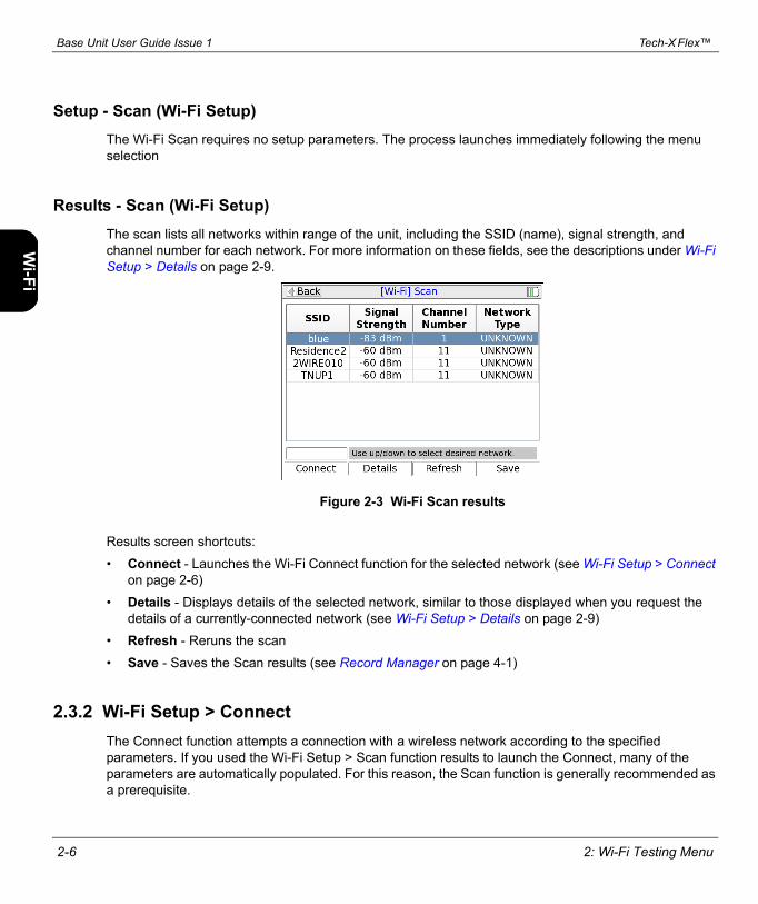
Setup - Scan (Wi-Fi Setup)The Wi-Fi Scan requires no setup parameters. The process launches immediately following the menu selection
Results - Scan (Wi-Fi Setup)The scan lists all networks within range of the unit, including the SSID (name), signal strength, and channel number for each network. For more information on these fields, see the descriptions under Wi-Fi Setup > Details on page 2-9.
Figure 2-3 Wi-Fi Scan results
Results screen shortcuts:
• Connect - Launches the Wi-Fi Connect function for the selected network (see Wi-Fi Setup > Connect on page 2-6)
• Details - Displays details of the selected network, similar to those displayed when you request the details of a currently-connected network (see Wi-Fi Setup > Details on page 2-9)
• Refresh - Reruns the scan
• Save - Saves the Scan results (see Record Manager on page 4-1)
2.3.2 Wi-Fi Setup > ConnectThe Connect function attempts a connection with a wireless network according to the specified parameters. If you used the Wi-Fi Setup > Scan function results to launch the Connect, many of the parameters are automatically populated. For this reason, the Scan function is generally recommended as a prerequisite.

Tech-X Flex™ Base Unit User Guide Issue 1
2: Wi-Fi Testing Menu 2-7
Intr
oW
i-Fi
10/1
00Sy
stem
IP/V
ideo
Spec
s
Once the unit successfully connects, the network parameters are saved in memory under the respective SSID (name).
NOTE: If you have trouble connecting, see If you cannot connect (troubleshooting tips) on page 2-3.
Setup - Connect (Wi-Fi Setup)
Table 2-1 Connect (Wi-Fi Setup) - Setup parameters page 1
Parameter Description
SSID (Service Set Identifier) Network name.
Channel Number Channel used by the network, typically 1 to 11 with variances possible based on the country of operation and applicable regulations. A Wi-Fi connection is based on a single channel which you must have correctly specified.
Network Type Type of network:INFRASTRUCTURE - A centralized network where the unit will negotiate with a single access point that manages the network overall.NOTE: Connection to “adhoc” Wi-Fi networks is currently not supported.
Security Type Type of security in use on the network:• WEP-64 - Wired Equivalent Privacy using a 40-bit key.• WEP-128 - Wired Equivalent Privacy using a 104-bit key.• NONE - No security (open access)

Base Unit User Guide Issue 1 Tech-X Flex™
2-8 2: Wi-Fi Testing Menu
IntroW
i-Fi10/100
SystemIP/Video
Specs
Table 2-2 Connect (Wi-Fi Setup) - Setup parameters page 2
Parameter Description
Key Type and Key Type of key and the key itself, as follows:• If Key Type = HEX, the Key must be a hexadecimal number. A hex digit
occupies four bits, so for WEP-64, a hex Key must be 10 digits (40 bits total). For WEP-128, a hex Key must be 26 digits (104 bits total).
• If Key Type = PASSPHRASE, the key must be the appropriate string that can be converted to the correct key using standard WEP algorithms. For WEP-64, a passphrase Key must be 5 characters/digits. For WEP-128, a passphrase Key must be 13 characters/digits.
WEP Authentication Type of initial authentication used by the wireless access point:• OPEN - Effectively no authentication to associate and connect; however, all
communications following the connection will be WEP-encrypted and therefore the unit must still have the correct key specified.
• SHARED - Requires matching keys to establish the initial connection, which involves a more detailed handshake transaction between the devices. Afterwards, all communications are WEP-encrypted similar to open authentication.
NOTE: This setting does not affect how you specify the Key Type and Key. It controls how the unit attempts initial negotiations only. Both open and shared WEP require a valid key.
WEP Key Slot WEP key slot.
Table 2-3 Connect (Wi-Fi Setup) - Setup parameters page 3
Parameter Description
Auto-Connect Specifies whether to add this network to the internal auto-connect list when the connection is launched, ON (yes) or OFF. For more information, see About the connection history and “auto-connect” networks on page 2-4.
Tech-X Flex™ Base Unit User Guide Issue 1
2: Wi-Fi Testing Menu 2-9
Intr
oW
i-Fi
10/1
00Sy
stem
IP/V
ideo
Spec
s
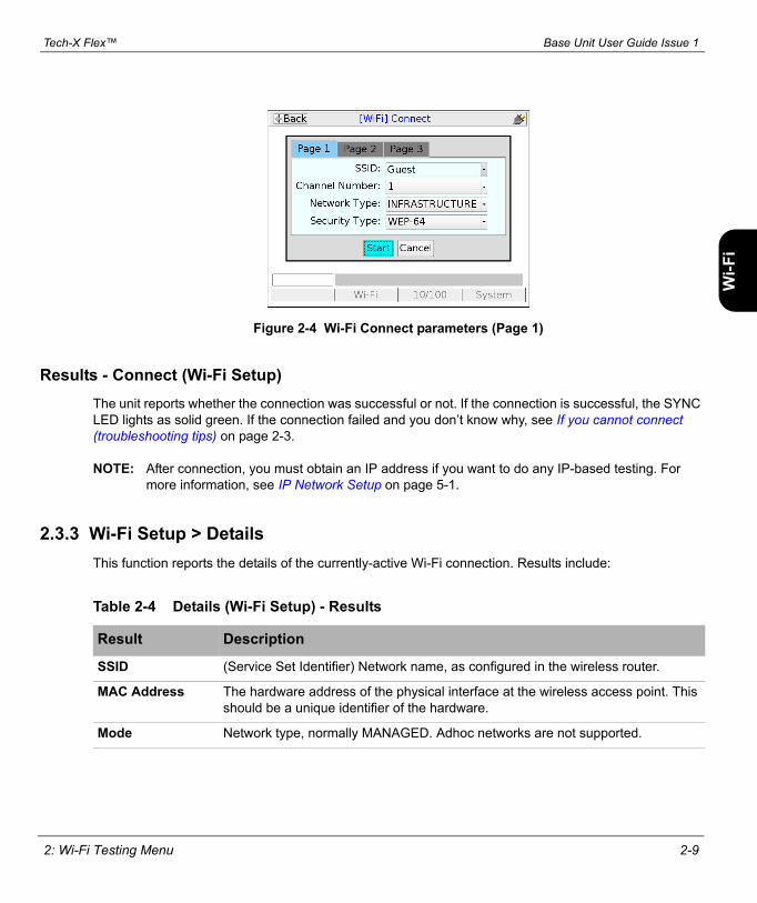
Figure 2-4 Wi-Fi Connect parameters (Page 1)
Results - Connect (Wi-Fi Setup)The unit reports whether the connection was successful or not. If the connection is successful, the SYNC LED lights as solid green. If the connection failed and you don’t know why, see If you cannot connect (troubleshooting tips) on page 2-3.
NOTE: After connection, you must obtain an IP address if you want to do any IP-based testing. For more information, see IP Network Setup on page 5-1.
2.3.3 Wi-Fi Setup > DetailsThis function reports the details of the currently-active Wi-Fi connection. Results include:
Table 2-4 Details (Wi-Fi Setup) - Results
Result Description
SSID (Service Set Identifier) Network name, as configured in the wireless router.
MAC Address The hardware address of the physical interface at the wireless access point. This should be a unique identifier of the hardware.
Mode Network type, normally MANAGED. Adhoc networks are not supported.

Base Unit User Guide Issue 1 Tech-X Flex™
2-10 2: Wi-Fi Testing Menu
IntroW
i-Fi10/100
SystemIP/Video
Specs
2.3.4 Wi-Fi Setup > View Auto-Connect NetworksThis function displays the current list of auto-connect networks. You can use the Delete shortcut to remove the selected network from the list. For more information, see About the connection history and “auto-connect” networks on page 2-4.
2.4 IP Network SetupIP Network Setup allows you to assign IP routing information to the unit in order to perform IP-based testing. This function operates similarly to other interfaces; however, note that when launched from the Wi-Fi menu, the assigned IP information applies to the wireless interface/connection only.
For more information on IP Network Setup parameters and results, see IP Network Setup on page 5-1.
NOTE: The unit must have an active wireless connection before IP Network setup is available (see Wi-Fi Setup on page 2-5).
2.5 PingPing testing over the Wi-Fi interface is similar to other interfaces. For more information, see Ping on page 5-4.
Security Type of security in use by the network:• NONE - No security (open access)• WEP - Wired Equivalent Privacy
Signal Strength Signal power level.
Channel Number Channel used by the network, typically 1 to 11 with variances possible based on the country of operation and applicable regulations. A Wi-Fi connection is based on a single channel which you must have correctly specified when attempting to connect.
Auto-connect Indicates whether the network is on the auto-connect list (see About the connection history and “auto-connect” networks on page 2-4).
Table 2-4 Details (Wi-Fi Setup) - Results
Result Description

Tech-X Flex™ Base Unit User Guide Issue 1
2: Wi-Fi Testing Menu 2-11
Intr
oW
i-Fi
10/1
00Sy
stem
IP/V
ideo
Spec
s
2.6 TracerouteTraceroute testing over the Wi-Fi interface is similar to other interfaces. For more information, see Traceroute on page 5-5.
2.7 Web BrowserNOTE: The web browser is a purchasable option. Please contact Spirent for more information.
Use of the web browser over the Wi-Fi interface is similar to other interfaces. For more information, see Web Browser on page 5-6.

Base Unit User Guide Issue 1 Tech-X Flex™
2-12 2: Wi-Fi Testing Menu
IntroW
i-Fi10/100
SystemIP/Video
Specs

Tech-X Flex™ Base Unit User Guide Issue 1
3: 10/100 Testing Menu 3-1
3: 10/100 Testing Menu
With the 10/100 testing menu, the unit is able to join a 10/100 Ethernet link and perform the following functions and tests:
• IP address retrieval/assignment (See IP Network Setup on page 5-1)
• IP ping (See Ping on page 5-4)
• Traceroute (See Traceroute on page 5-5)
• Internet web page request (See Web Browser on page 5-6)
• IP video testing (See IP Video testing on page 5-7)
• Ethernet bridging and passive testing (See Passive testing on page 3-4)
Figure 3-1 10/100 main menu
NOTE: On the unit, you can use either 10/100 port for single-ended tests such as ping and traceroute. For more information, see About the 10/100 ports and connections on page 3-2.

Base Unit User Guide Issue 1 Tech-X Flex™
3-2 3: 10/100 Testing Menu
IntroW
i-Fi10/100
SystemIP/Video
Specs
3.1 Functionality noteYour unit may or may not include all the functionality described in this section, dependent upon your licensing agreement with Spirent. Please contact Spirent for more information.
3.2 About the 10/100 ports and connectionsThe unit has two physical 10/100 ports which are connected internally by a functional Ethernet switch. Therefore, when performing single-ended tests such as ping or traceroute, you may use either port. When setting up an Ethernet bridge for passive tests, the order of the ports is likewise not important.
NOTE: On the physical port, the unit is able to auto-detect the receive and transmit channels; therefore you may use straight-through or crossover Ethernet cables for any application.
3.3 10/100 testing diagramThe following diagram shows a typical setup for active, single-ended tests. For more information on the setup for bridged, passive testing, see Passive testing on page 3-4.
Figure 3-2 Typical 10/100 testing diagram
Ping, traceroute, web browsing, IPTV video testing
Provider network/ISP
Home router
Home computer
Ping

Tech-X Flex™ Base Unit User Guide Issue 1
3: 10/100 Testing Menu 3-3
Intr
oW
i-Fi
10/1
00Sy
stem
IP/V
ideo
Spec
s
3.4 IP Network SetupIP Network Setup allows you to assign IP routing information to the unit in order to perform IP-based testing. This function operates similarly to other interfaces; however, note that when launched from the 10/100 menu, the assigned IP information applies to the 10/100 interface/connection only.
For more information on IP Network Setup parameters and results, see IP Network Setup on page 5-1.
NOTE: The unit must be connected to a suitable access device before attempting IP Network setup (see 10/100 testing diagram on page 3-2).
3.5 PingPing testing over the 10/100 interface is similar to other interfaces. For more information, see Ping on page 5-4.
3.6 TracerouteTraceroute testing over the 10/100 interface is similar to other interfaces. For more information, see Traceroute on page 5-5.
3.7 Web BrowserNOTE: The web browser is a purchasable option. Please contact Spirent for more information.
Use of the web browser over the 10/100 interface is similar to other interfaces. For more information, see Web Browser on page 5-6.
3.8 IP Video TestsNOTE: Video testing is a purchasable option. Please contact Spirent for more information.
Active IP video testing on the 10/100 interface is similar to other interfaces. For more information, see IP Video testing on page 5-7.

Base Unit User Guide Issue 1 Tech-X Flex™
3-4 3: 10/100 Testing Menu
IntroW
i-Fi10/100
SystemIP/Video
Specs
3.9 Passive testingNOTE: Passive testing is a purchasable option. Please contact Spirent for more information.
Passive testing allows non-intrusive testing on a bridged Ethernet link. The following sections describe passive testing and bridge setup in more detail.
3.9.1 Unit setup for passive testingBecause the two 10/100 ports are joined internally by a functional Ethernet switch, the unit is inherently capable of bridging an Ethernet link when placed in the middle. With a bridged link, the unit can passively monitor traffic between the ports (that is, the traffic flowing across the “bridge”), such as during a passive measurement of video quality. The ports are always active; therefore, the bridge capability is always active, with the monitoring feature activated when a passive test is run.
With a passive test, the unit does not send any traffic on the link, nor does it interfere with any traffic passing through the link. However, an active link will be naturally disrupted when the unit is physically placed in the middle. For a passive test to run, it is required that the desired traffic is activated or restored between the bridged endpoints before the testing begins. Using the example of passive video testing, consider the following typical setup:
Figure 3-3 Bridged (passive) video testing
To set up the video test in this example, you should:
Active video stream
ISP / IPTV video service
Router/gateway
Set-top box
Passive monitoring
Ethernet

Tech-X Flex™ Base Unit User Guide Issue 1
3: 10/100 Testing Menu 3-5
Intr
oW
i-Fi
10/1
00Sy
stem
IP/V
ideo
Spec
s
1. Connect the physical wires between the endpoints, from router-to-unit and unit-to-STB.2. Verify that communications between the bridged endpoints are restored. In this example, you should
be able to see the video on the TV.3. Set up and run the desired test on the unit.
The following notes apply:
• Following successful IP Network Setup, you can also perform single-ended active tests while the link is bridged, in either direction. In the previous example, you should be able to ping the STB if you know its IP address, as well as anywhere upstream, including the internet.
• You can use either crossover or straight-through Ethernet cables for any connections to the unit.
3.9.2 Passive Video Quality of Service (QoS)Select 10/100 menu > Passive Tests > Video Quality of Service.
The passive video quality test operates identically to the active version, with the following exceptions:
• Instead of actively joining a video stream, the unit monitors an existing stream on the bridged link. Therefore, the video stream must be active between the bridged endpoints before the test can begin.
• Because the unit itself does not need to join the stream, the passive test supports both unicast and multicast streams. Existing stream traffic can be identified by the specified IP address and port alone.
For detailed information on the video QoS test parameters and results, see Video Quality of Service (QoS) on page 5-8.

Base Unit User Guide Issue 1 Tech-X Flex™
3-6 3: 10/100 Testing Menu
IntroW
i-Fi10/100
SystemIP/Video
Specs

Tech-X Flex™ Base Unit User Guide Issue 1
4: System Menu 4-1
4: System Menu
The System menu provides access to general system configuration.
Figure 4-1 System main menu
4.1 Record ManagerSelect System > Record Manager.
The Record Manager is used to create, delete, and view record files, which are special files used to store test results. When you invoke the “Save” function in a results screen, they are saved to a record file. For non-continuous, self-terminating tests, the full results set is saved at the end of testing. For continuous tests, you can control when saving is active, during which time a full results set is saved following the end of each reporting interval.
At any given time, a single record file is considered the active file, which is where results are saved when you invoke the Save function. If you have never created any record files, the unit uses a “DEFAULT” record file until you specify otherwise. If you do not have the need for multiple record files, the default record may be sufficient for general use.

Base Unit User Guide Issue 1 Tech-X Flex™
4-2 4: System Menu
IntroW
i-Fi10/100
SystemIP/Video
Specs
NOTE: All records and associated results remain on the unit until manually deleted. A unit shutdown will not delete record data.
The unit has no specific maximum to the number of record files or the amount of results that any record can contain. However, it does have a certain overall limit related to the constraints of physical memory. A general rule which might be useful is to have no more than 30 record files on the unit at once, each with no more than 20 sets of test results. The actual numbers can vary, though, especially considering the type of results you are saving. For example, the results data set from a video test is many times larger than a ping test.
The Record Manager lists record files in the Name column and indicates the currently-active file in the Active column. The actions that may be invoked by the respective function key include:
4.2 10/100 Admin PortSelect System > 10/100 Admin Port.
This function assigns IP data to the internal management interface of the unit. It is similar to the IP Network Setup for the 10/100 test interface, except that it provides access to the internal management of the unit, rather than the test interface. If successful, this function allows management communication through the same physical 10/100 ports used for 10/100 testing.
Table 4-1 Record Manager functions
Function Description
New Creates a new record file. The name can have any alphanumeric name, often reflecting a work order number or a customer location.NOTE: Do not begin a record name with a period (N1 key), otherwise it will not
appear in the Record Manager.
Delete Deletes the selected file. This action cannot be undone.
Active Makes the select file the active file, where results will be stored during subsequent save actions.
View Opens the selected file for viewing in the form of a tree view of results. Normally, a results set includes one branch with shows details on the original test setup, with a second branch indicating the success or failure of the operation with additional details as applicable.

Tech-X Flex™ Base Unit User Guide Issue 1
4: System Menu 4-3
Intr
oW
i-Fi
10/1
00Sy
stem
IP/V
ideo
Spec
s
Currently, this function is used as a prerequisite for management activities such as firmware upgrades and channel guide imports. It does not provide general access to the operating system of the unit. For more information on firmware upgrades, see Update Firmware on page 4-10.
4.3 Set Date and TimeSelect System > Set Date And Time.
The date and time are used to timestamp all saved results in the Record manager. They are also used for various internal functions, described in this document elsewhere as appropriate.
The date and time must be entered using the following formats:
• Date - YYYY-MM-DD
• Time - HH:MM:SS
To set the date or time, select either parameter and press a number on the keypad to initiate the numeric entry screen. You must enter all characters that are requested, using leading zeros as necessary to pad empty spaces. For example:
09:10:00
...would set the time to 9:10 a.m. Note that the unit uses 24 hour time. For example, 9:10 p.m. would be set as 21:10:00.
Figure 4-2 Setting the date and time

Base Unit User Guide Issue 1 Tech-X Flex™
4-4 4: System Menu
IntroW
i-Fi10/100
SystemIP/Video
Specs
4.4 Auto Sleep ModeSelect System > Auto Sleep Mode.
This function sets the maximum amount of idle time after which the unit automatically enters “sleep mode” in order to save battery power. It does not apply when the unit is powered by an external source. For more information on sleep mode, see Powering on/off and sleep mode on page 1-9.
4.5 Version InfoSelect System > Version Info.
This function provides information about hardware and firmware versioning currently applicable to the unit, including the attached module, if any. This information may be required when obtaining technical support from Spirent. It may also be useful for verification before and/or after firmware upgrades.
Figure 4-3 Version Info
4.6 Battery StatusSelect System > Battery Status.
This function provides detailed information about the battery and current charging conditions. For the general user, the Estimated Remaining Capacity percentage may be the most useful.

Tech-X Flex™ Base Unit User Guide Issue 1
4: System Menu 4-5
Intr
oW
i-Fi
10/1
00Sy
stem
IP/V
ideo
Spec
s
4.7 Channel Guide/Network SetupSelect System > Channel Guide/Network Setup.
This function allows you to set common parameters for all video testing, including testing on different interfaces. In most cases, these are global configuration parameters that are set once and remain static for subsequent testing. In cases where the same parameter appears in a video test setup screen, the setting here acts as the default.
Table 4-2 Channel Guide/Network Setup - Page 1 parameters
Parameters Description
Use Guide Indicates whether a channel guide is currently active for video test setup. For more information, see About channel guides on page 4-7.
Guide Name Name of the active channel guide, only applicable when Use Guide is set to Yes. The field allows you to select from the guides currently on the unit, if any. If the field is blank, no channel guides have been imported. For more information, see About channel guides on page 4-7.
Channel Format If Use Guide = Yes, this setting determines how channels from the guide are initially sorted in a video test setup screen, either by number or abbreviation. In either case, the number or abbreviation comes directly from the guide.
IGMP Version Version of IGMP to use for multicast join/leave requests. This must reflect an IGMP type in use on the network where the request is made.Options include:• 1 - IGMP version 1• 2 - IGMP version 2• 3 - IGMP version 3• D - Dynamic. The unit attempts to monitor existing IGMP traffic on the
network to determine the type in use.

Base Unit User Guide Issue 1 Tech-X Flex™
4-6 4: System Menu
IntroW
i-Fi10/100
SystemIP/Video
Specs
Table 4-3 Channel Guide/Network Setup - Page 2 parameters
Parameters Description
Int’l Code Country/continent code. This specification allows the analysis to adjust the quality metric scores according to statistical data available in different parts of the world.Options include:• NA - North America• SA - South America• EU - Europe • AF - Africa • AS - Asia • JP - Japan • AUS - Australia
Coder Class Video coder class, which describes the ability of the stream to tolerate packet loss with respect to perceived quality. The coder class is determined by two contributing factors:• Codec - Some codecs, particularly older codecs, are very sensitive to packet
loss and degrade very quickly with small amounts of loss.• Error correction and concealment - A number of loss mitigation techniques
may be employed to conceal packet loss, typically involving coordination between the video server and client where checksum and other validation methods allow missing data to be supplemented.
The specified value determines how heavily the analysis weights the effects of packet loss. For example, if you specify an operation at high rates of loss, any detected loss will have less of an effect on final quality scores. This is normally a static setting on any given network that does not change between tests.Options include:• A - Stream can operate over networks with up to 20% packet loss• B - Operation with up to 10% loss• C - Operation with up to 5% loss• D - Operation with up to 0.5% loss

Tech-X Flex™ Base Unit User Guide Issue 1
4: System Menu 4-7
Intr
oW
i-Fi
10/1
00Sy
stem
IP/V
ideo
Spec
s
4.7.1 About channel guidesA channel guide provides a shortcut for specifying IP video channels during video testing. When the unit joins and/or monitors a video stream for testing, it requires the IP address and port of that stream. If you do not have a channel guide on the unit, you must enter the address and port manually. However, if you do have an active channel guide that includes the respective channel, it allows you to select a simple channel number or a more intuitive channel abbreviation, such as CNN or HBO. The unit then looks up the address and port in the guide instead of requiring a manual entry. A channel guide also provides a series of other default testing parameters for each channel, such codec type and media stream information.
Within the channel guide file itself (not on a video test screen), a sample entry might appear as follows:
<channel-info> <channel-number>001</channel-number> <channel-abbreviation>ESPN</channel-abbreviation> <IP-address>239.255.1.101</IP-address> <IP-port>3002</IP-port> <encapsulation>UDP</encapsulation> <codec>MPEG2</codec> <jitter-mode>FIXED</jitter-mode> <gop-type>GOP_C</gop-type> <gop-length>15</gop-length> <loss-sensitivity>0</loss-sensitivity> <packet-loss-concealment-level>2</packet-loss-concealment-level> <image-complexity>0</image-complexity></channel-info>
...where the element names intuitively denote each respective parameter, such as <IP-address> and <IP-port>. To be functional, a channel guide must be well-formed and conform to the proper schema. For more information on schemas and channel guide generation, please contact Spirent.
4.7.2 Importing channel guides to the unitTo import channel guides to the unit, you must follow the procedures described in this section. Channel guides cannot be imported by any other means.
NOTE: The procedures in this section are an abbreviated version. If you need further assistance, please contact Spirent Technical Support.
The import requires two basic steps:

Base Unit User Guide Issue 1 Tech-X Flex™
4-8 4: System Menu
IntroW
i-Fi10/100
SystemIP/Video
Specs
1. Place the channel guides on a networked computer that has an approved FTP server running. This section describes how to install and set up that server.
2. Run the import function on the unit.
Note the following:
• You must be able to connect the unit to the FTP server host computer over Ethernet/IP
• All existing channel guides on the unit are deleted or overwritten during the import
• Spirent recommends a maximum of eight channel guides during an import
To install and set up the FTP server
Currently, the only approved FTP server is FileZilla, a free, open-source application available at http://filezilla-project.org/ at the time of this writing. The FileZilla server runs on the Windows platform only. To set up FileZilla on a host computer:1. Download the FileZilla server package (not the client).2. Launch the package and install according to default settings, unless customization is desired.3. Open the Server Interface, normally with a new icon on the desktop. For new installs, you can leave
the password blank in the Connection prompt.4. In the interface window, select Edit > Users.5. In the Users window, click Add to add a new FTP user account, which the unit will use to retrieve
channel guide files.6. In the Add user account window, specify a user name (such as techxflex) and click OK.7. Back in the Users window, click the General page link, and specify a password if desired.
Important! The password is optional, but if you specify one, you must remember what it is when launching the import on the unit.
8. In the Users window, click the Shared folders page link, then click Add to specify the folder where the channel guide files are stored. Important! When you run the import, every file from this folder is imported from the unit. Therefore, the folder should contain channel guide files only.
9. In the Users window, click OK to save the new user.
To run the import on the unit
With FileZilla running on the host computer:1. Connect the 10/100 interface of the unit to the network where the host computer resides.2. On the unit, select System > 10/100 Admin Port and obtain an IP address for the admin interface
(see 10/100 Admin Port on page 4-2).3. On the unit, select System > Download Channel Guide and enter the requested information, as
follows:

Tech-X Flex™ Base Unit User Guide Issue 1
4: System Menu 4-9
Intr
oW
i-Fi
10/1
00Sy
stem
IP/V
ideo
Spec
s
4. On the unit, click Start to initiate the import.If the import is successful, you can select System > Channel Guide/Network Setup and verify the import by looking at the list in the Guide Name field.If the import fails, check the FTP server setup and the network connection between the unit and the host computer. Either device should be able to ping the other.
4.8 Download Channel GuideSelect System > Download Channel Guide.
For more information on importing channel guides to the unit, see Importing channel guides to the unit on page 4-7.
4.9 Wireless ON/OFFSelect System > Wireless ON/OFF.
If set to ON, this setting causes the following to occur:
• When the unit is powered up, a Wi-Fi connection is automatically attempted, based on the internal list of auto-connect networks. For details on how auto-connection works, see About the connection history and “auto-connect” networks on page 2-4.
• The current Wi-Fi connection remains active while other menus and interfaces are in use. If the auto-connection was successful, it is immediately available for use and remains active as long as the unit is within range.
If set to OFF, the Wi-Fi interface can still be used for testing; however, its general behavior is identical to other interfaces. For more information, see Selecting the active interface on page 1-13.
Server The IP address or DNS name of the host computer where the FTP server application is running.
Port The port on which the FTP server is listening for requests. The default is 21 but can be changed in the FTP server setup.
User ID The name of the user account that you set up in the previous procedure.
Password The password of the user account, if one was specified.

Base Unit User Guide Issue 1 Tech-X Flex™
4-10 4: System Menu
IntroW
i-Fi10/100
SystemIP/Video
Specs
4.10 Calibrate TouchscreenSelect System > Calibrate Touchscreen.
This function calibrates the touchscreen display for optimal response. Calibration should be done after firmware upgrades, after battery replacement, or if the screen response begins to degrade after heavy use.
The process requires you to touch the screen in several places with a stylus or other approved device. Follow the instructions on the screen.
4.11 Licensed OptionsSelect System > Licensed Options.
This function reports which optional features are currently enabled for the base unit and modules (if any), which may be required when seeking technical support. It also allows you to manually enable features by entering valid key codes, which is may be required to enable licensed features on a new unit. To enter a key code, press Update Key (F1) and enter the key exactly as provided by Spirent. Note the following:
• For licensing changes to take effect, you must reboot the unit or cycle it through sleep mode. For more information, see Powering on/off and sleep mode on page 1-9.
• The unit requires a unique key code for each licensed feature. For example, to enable both the web browser and IP video testing, you need to enter two different codes.
• You do not need to enter anything except the code itself. The unit will recognize the feature to which it applies and then list that feature as enabled.
• A key code is specific to a unit and will not work on any other unit.
• Key codes must be provided by Spirent. In some cases, the codes required for your licensed feature set are shipped in the package with the unit. If you have trouble with the codes or require new codes for any reason, please contact Spirent.
4.12 Update FirmwareSelect System > Update Firmware.
This function initiates the firmware upgrade process. You must supply the IP address of a networked host on the active 10/100 link from which the unit will retrieve the firmware package. Note the following:

Tech-X Flex™ Base Unit User Guide Issue 1
4: System Menu 4-11
Intr
oW
i-Fi
10/1
00Sy
stem
IP/V
ideo
Spec
s
• The host that contains the firmware must be set up in a specific manner. Please contact Spirent for a separate document that provides details on this setup and other information about firmware upgrades.
• The 10/100 admin port must be set up before this menu command becomes available (see 10/100 Admin Port on page 4-2).
Please contact Spirent for additional information about upgrading firmware.

Base Unit User Guide Issue 1 Tech-X Flex™
4-12 4: System Menu
IntroW
i-Fi10/100
SystemIP/Video
Specs

Tech-X Flex™ Base Unit User Guide Issue 1
5: IP and Video Testing 5-1
5: IP and Video Testing
This section describes the suite of IP and video (IPTV) functions available on the unit. These tests are available over various interfaces on the unit, including the Wi-Fi and Ethernet interfaces, and modular interfaces such as MoCA. Not all tests are available for all interfaces; see the respective documentation for specific testing support.
Once an interface is correctly configured with routable IP information, testing from that interface should be generally identical to any other. For example, ping testing from the Wi-Fi interface should be identical to ping testing from the Ethernet interface, except that it is launched from a different menu. Therefore, the information is consolidated here and applies generally to any interface that supports the respective test.
To configure an interface with routable IP information, use the IP Network Setup function (see IP Network Setup on page 5-1). Once setup is successful, the following tests may be available, depending upon test support of the respective interface:
• IP Network Setup on page 5-1
• Connection Information on page 5-3
• Ping on page 5-4
• Traceroute on page 5-5
• Web Browser on page 5-6
• IP Video testing on page 5-7
NOTE: Your unit may or may not include all the functionality described in this section, dependent upon your licensing agreement with Spirent. Contact an account manager for more information.
5.1 IP Network SetupThis function is used to configure the active interface as necessary to join an IP network. For example, if you are using the 10/100 menu, this function configures the 10/100 interface with the IP routing

Base Unit User Guide Issue 1 Tech-X Flex™
5-2 5: IP and Video Testing
IntroW
i-Fi10/100
SystemIP/Video
Specs
information required to send and receive IP traffic. For any interface, IP Network Setup is a required prerequisite to any test that sends and/or receives IP data over that interface.
IP Network Setup must be performed each time the unit is started up, for the interface(s) that you intend to use. Furthermore, you may need to run the setup again after switching test menus, if the menu change activates a different interface on the unit. To facilitate frequent setup actions, the unit supports DHCP, which is the preferred method of configuration if a DHCP server is available. By using DHCP, you can more easily assure that valid IP routing information is assigned which does not conflict with any other host on the network.
Before attempting IP Network Setup, the unit must be linked up with the proper access device, according to interface type. For example, if you are performing 10/100 testing, the unit should be connected to a switch or router with an Ethernet cable. Or, for Wi-Fi testing, the unit should be within range and synchronized with an active Wi-Fi node.
NOTE: If you disconnect the unit and reconnect it to another network, you should rerun the network setup. IP information for one network may not be routable on another.
5.1.1 Setup - IP Network Setup
If you select static assignment, the unit requires you to manually enter the IP address, subnet mask, default gateway, and DNS server. The unit will accept any information that you specify and attempt to use it for active test traffic, whether it is routable or not. Therefore, you should be sure to enter valid information, otherwise subsequent IP-based testing will fail. In addition, note the following:
Table 5-1 IP Network Setup - Setup parameters
Parameter Description
Type Method for assigning IP information:• STATIC - Static assignment. If you select this method, the unit will request the
static address information.• DHCP - DHCP assignment. If a DHCP server is available, all IP information is
assigned automatically. DHCP is a common method for IP address assignment within a home network and most home network routers include a DHCP server.NOTE: If the unit fails to get an address with DHCP, see Results - IP
Network Setup on page 5-3.

Tech-X Flex™ Base Unit User Guide Issue 1
5: IP and Video Testing 5-3
Intr
oW
i-Fi
10/1
00Sy
stem
IP/V
ideo
Spec
s
• Ensure that you have specified generally valid IP information. For example, the unit cannot assign an address of 0.0.0.0 because it is not valid for IP communications.
• For static assignment, the DNS server address is optional. However, if you do not specify a valid server, you must know the target IP address for any IP-based tests. That is, the unit will be unable to resolve domain names such as www.google.com.
5.1.2 Results - IP Network SetupThe results screen displays either the assigned IP information, or a failure message if the process failed. If a DHCP operation fails, check the following:
• The unit is properly connected to an active, networked device. For example, when using the 10/100 interface, the Ethernet cable must be properly connected. Or, for the Wi-Fi interface, the unit must be within range of an active wireless node.
• The target network has an active DHCP server. In a home network, the DHCP server is normally incorporated with the home router, in which case you may need to log into the router to ensure that the DHCP server has not been disabled. See the router documentation for more information.
Figure 5-1 Successful IP Network Setup
5.2 Connection InformationThis function reports the IP information that is currently assigned to the active interface and is identical to the results screen from a successful IP Network Setup. For more information, see IP Network Setup on page 5-1.

Base Unit User Guide Issue 1 Tech-X Flex™
5-4 5: IP and Video Testing
IntroW
i-Fi10/100
SystemIP/Video
Specs
5.3 PingIP Ping is a basic connectivity test that verifies whether a specific IP address can be reached. It sends a set of ICMP echo requests to an IP address and reports whether replies are successfully received. The request is sent via the active interface of the unit and requires that routable IP information is assigned to that interface. For more information, see IP Network Setup on page 5-1.
5.3.1 Setup - Ping
5.3.2 Results - PingAlong with details about each individual ping request, the unit also reports the following summary information:
Table 5-2 Ping - Setup parameters
Parameter Description
Destination Address
Target address for the ping request, either a dotted IP address or a URL if a DNS is available. For example:
208.22.58.142
www.google.com
Table 5-3 Ping - Results
Result Description
Packets Sent Number of ping requests sent to the address
Packets Received Number of ping requests reported as successfully received
Packets Lost Percentage of ping requests that were lost (Packets Sent - Packets Received)
Approximate Round Trip Average time for a ping requests to reach its destination and then for the unit to receive the success report

Tech-X Flex™ Base Unit User Guide Issue 1
5: IP and Video Testing 5-5
Intr
oW
i-Fi
10/1
00Sy
stem
IP/V
ideo
Spec
s
Figure 5-2 Successful Ping results
5.4 TracerouteThis test is the standard ICMP traceroute function that sends three traceroute requests to a destination address and reports every router “hop” along the path, up to 30 hops. The results provides a topological view of the route that the packets used to reach the destination.
The request is sent via the active interface and requires that routable IP information is assigned to that interface. For more information, see IP Network Setup on page 5-1.
5.4.1 Setup - Traceroute test
Table 5-4 Traceroute - Setup parameters
Parameters Description
Destination IP Address
Target address for the traceroute request, either a dotted IP address or a URL if a DNS is available. For example:
208.22.58.142
www.google.com

Base Unit User Guide Issue 1 Tech-X Flex™
5-6 5: IP and Video Testing
IntroW
i-Fi10/100
SystemIP/Video
Specs
5.4.2 Results - Traceroute testThe unit reports the IP address of each sequential hop along the path to the target, along with the roundtrip time required for each hop to receive the request and the unit to receive acknowledgement. Because three independent requests are sent, each hop shows three different roundtrip times. An asterisk appears if a time cannot be determined, such as a response timeout when a network element cannot or will not return a traceroute acknowledgement.
Figure 5-3 Successful Traceroute results
5.5 Web BrowserNOTE: The web browser is a purchasable option. Please contact Spirent for more information.
The web browser allows you to access web pages from the internet and view them on the screen. It may be especially useful for verifying that internet access is available, beyond a simple ping test. If a residential subscriber cannot view a web page but you can with the unit, you can normally conclude that the trouble exists with the subscriber’s web browser, computer, or home network configuration. It may also be used to verify that a DNS is available.
The web browser is similar to a browser used on a desktop computer, except that the smaller screen may require more use of the scroll bars. Furthermore, aside from basic hyperlinks, most webpage controls may not work correctly. In some cases, complex pages with extensive internal scripting may not display correctly or at all, so it is recommended that you use simple, fast-loading web pages to perform tests. In summary, the browser is intended as a testing tool, not as a fully-functional interface to the internet.
To access the web browser, the active interface must be configured with valid, routable IP information. For more information, see IP Network Setup on page 5-1.

Tech-X Flex™ Base Unit User Guide Issue 1
5: IP and Video Testing 5-7
Intr
oW
i-Fi
10/1
00Sy
stem
IP/V
ideo
Spec
s
5.5.1 Setup - Web Browser
5.6 IP Video testingIP video testing support includes:
• Subjective quality assessment of viewer experience
• Comprehensive statistics on multimedia transport streams
• Video channel change times
Video testing is supported on IP multicast streams using the MPEG codec. During testing, the unit joins the stream and emulates an IPTV subscriber, providing a comprehensive view of the subscriber experience.
NOTE: Depending upon the test interface, passive testing of video quality for unicast and multicast streams may also be available.
Specific video functions include:
Table 5-5 Web Browser - Setup parameters
Parameters Description
URL Target address of the web page to load, either a dotted IP address or a URL if a DNS is available. For example:
208.22.58.142
www.google.com
Note the following:• When entering a URL, case is unimportant because all characters are
converted to lower case when the browser is launched.• The unit remembers the recent addresses you entered.

Base Unit User Guide Issue 1 Tech-X Flex™
5-8 5: IP and Video Testing
IntroW
i-Fi10/100
SystemIP/Video
Specs
• Channel Guide/Network Setup on page 4-5 (System menu)
• Video Quality of Service (QoS) on page 5-8
• Channel Change Time on page 5-30
5.6.1 Video Quality of Service (QoS)
NOTE: Video testing is a purchasable option. Please contact Spirent for more information.
This test provides subjective no-reference quality scores on a specific IPTV channel stream, along with a set of network parameters, picture frame statistics, and other transport stream information.
For a single-ended, active test, the unit must emulate a video endpoint and join a multicast stream, after which it performs the quality assessment on the traffic sent directly to it. Some interfaces, such as the 10/100 interface, provide a bridging/mirroring mechanism where the unit can be placed between two devices and passively monitor an existing stream. In this case, the unit does not join the stream itself and therefore supports the measurement of unicast streams as well. For more information on how the passive bridging process works with the Ethernet interface, see Unit setup for passive testing on page 3-4.
For more details on how the quality assessment works, see How the analysis works - An overview on page 5-27.
NOTE: The analysis focuses primarily on the data captured from the MPEG transport stream. For more information about MPEG transport, see the information under Digital video concepts overview on page 5-20, including About MPEG transport on page 5-23.
Setup - Video Quality of Service
NOTE: If the unit has an active channel guide, the display will first present a channel selection screen when the test setup is initiated. After channel selection, the normal setup screen will appear, with the certain parameters prepopulated, such as the IP Address and Port. The use of a channel guide, if available, is generally recommended. For more information, see Channel Guide/Network Setup on page 4-5.

Tech-X Flex™ Base Unit User Guide Issue 1
5: IP and Video Testing 5-9
Intr
oW
i-Fi
10/1
00Sy
stem
IP/V
ideo
Spec
s
Figure 5-4 Video QoS Setup - Page 1 (with channel guide)
Table 5-6 Video QoS test - Setup parameters
Parameter Description
Channel NumChannel Abbr
If a channel guide was used, the channel number and abbreviation that was selected in the previous screen. If no channel guide is active, these fields do not appear. For more information on channel guides, see About channel guides on page 4-7.
IP Address IP address of the video stream. If you selected a channel from the channel guide, this field is automatically populated.The IP address specified must reflect the destination IP address for video stream packets; that is, the first address contained in the IP packet headers. For a multicast stream, this will be a multicast IP address, not an IP address of a host on the network under test. For a unicast stream, this must be the IP address of the destination device on the network, such as an STB. For a discussion on multicast packet addressing and transport versus unicast, see About IP multicast on page 5-25.

Base Unit User Guide Issue 1 Tech-X Flex™
5-10 5: IP and Video Testing
IntroW
i-Fi10/100
SystemIP/Video
Specs
IP Port UDP port of the video stream. Similar to the IP Address, this must be the destination port in the UDP packet header. If you selected a channel from the channel guide, this field is automatically populated. Optionally, you can select As IP Add from the drop-down list which indicates to ignore the port and use the IP address exclusively for identifying video stream packets. In the case of unicast streams where packets are addressed to a network device such as an STB, it can be more difficult to determine the UDP port than the IP address of that device. Therefore, this option allows traffic analysis based on IP address alone. While the STB may be receiving some data that is not part of the video stream, it is likely that most traffic will be video data that qualifies for analysis.
Duration Duration of the test in seconds, or Continuous to run the test until manually stopped.
Interval Interval at which to report a full set of current measurement results, applicable to continuous tests only.
Encapsulation Method
Encapsulation type of the stream under test.• RTP• UDP
IGMP Version Version of IGMP to use for multicast join/leave requests. This must reflect an IGMP type in use on the network where the request is made.Options include:• 1 - IGMP version 1• 2 - IGMP version 2• 3 - IGMP version 3• D - Dynamic. The unit attempts to monitor existing IGMP traffic on the network
to determine the type in use.
Codec Video codec used for the stream under test.• MPEG2• MPEG4• H264
Table 5-6 Video QoS test - Setup parameters
Parameter Description

Tech-X Flex™ Base Unit User Guide Issue 1
5: IP and Video Testing 5-11
Intr
oW
i-Fi
10/1
00Sy
stem
IP/V
ideo
Spec
s
Jitter Mode Type of jitter buffer emulation used.Options include:• F or FIXED - The jitter buffer uses a constant fixed delay. The jitter buffer is
bounded by a nominal and maximum delay, where the nominal delay dictates the actual delay and the maximum delay dictates the maximum number of packets that can be stored in the jitter buffer.
• A or ADAPTIVE - The jitter buffer is bounded by a minimum, nominal and maximum delay, where the minimum delay dictates the minimal accepted jitter buffer delay, nominal delay dictates the starting delay and the maximum delay dictates the maximum delay of the jitter buffer. The maximum number of packets that can be stored in the jitter buffer is a set fraction of the maximum delay.
GOP Type Video coder group of pictures (GOP) structure, representing the frame sequence in use on the stream with respect to I, P, and B frames. This value is used only as a default if the actual frame types and GOP structure cannot be dynamically detected from the stream.Options include:• A - I-frames only, for example:
III…I
• B - One I-frame followed by P-frames, for example:IPPP...PIPPP...
• C - One I-frame followed by P- and B-frames with two B-frames between each pair of anchor frames, for example:IBBPBBP...BBIBBP...
• D - All P-frames, for example:PPPP...P
• E - One I-frame followed by P- and B-frames with one B-frame between each pair of anchor pictures, for example:IBPBP...BIBP...
For more information about MPEG pictures, see About IP multicast on page 5-25.
Table 5-6 Video QoS test - Setup parameters
Parameter Description

Base Unit User Guide Issue 1 Tech-X Flex™
5-12 5: IP and Video Testing
IntroW
i-Fi10/100
SystemIP/Video
Specs
GOP Length Number of frames in a group of pictures (GOP) on the stream, related to the GOP type. This is essentially the I-frame update interval; that is, the number of frames from one I-frame to the next. This value is used only as a default if the actual frame types and GOP structure cannot be dynamically detected from the stream.Range:1 - 100
Loss Sensitivity This defines how much the quality assessment should be sensitive towards packet loss and discards. A higher value indicates the video stream is more sensitive to packet loss/discard. When set higher, the calculation model will respond more rapidly to packet loss on the network under test, and packet loss will have a greater impact on the calculated score. If set lower, the results will be less affected by packet loss. This setting makes the analysis tunable for different varieties of encoders and various network environment conditions.
Concealment Level This parameter defines the effectiveness of the packet loss concealment algorithm use by the encoder. A higher value indicates a better PLC algorithm. This setting helps compensate for reduced packet loss due to regeneration by technologies such as forward error correction (FEC). In other words, it affects how sensitive the quality assessment is to packet loss, with some similarity to the loss sensitivity setting. A higher setting indicates that overall packet loss will affect the quality score less. A setting of zero or none indicates no concealment, meaning that packet loss will have the most impact to video quality, with respect to this parameter's influence.Valid values are:0 to 50
Complexity This parameter defines the video content coding factor. A higher value indicates the video stream can be encoded using a lower bit rate to achieve a given quality.Valid values are:-50 to 50
Table 5-6 Video QoS test - Setup parameters
Parameter Description

Tech-X Flex™ Base Unit User Guide Issue 1
5: IP and Video Testing 5-13
Intr
oW
i-Fi
10/1
00Sy
stem
IP/V
ideo
Spec
s
Original Quality Original picture quality. This value represents the subjective quality of the video before encoding, which is the theoretical maximum that the quality ever could be after encoding, transport, and decoding.Valid values are:256 - 1280, proportional to the 1.0 to 5.0 MOS range, scaled by a factor of 256. For example, a value of 1242 is equivalent to a MOS of 4.85.
Coder Class Video coder class, which describes the ability of the stream to tolerate packet loss with respect to perceived quality. The coder class is determined by two contributing factors:• Codec - Some codecs, particularly older codecs, are very sensitive to packet
loss and degrade very quickly with small amounts of loss.• Error correction and concealment - A number of loss mitigation techniques
may be employed to conceal packet loss, typically involving coordination between the video server and client where checksum and other validation methods allow missing data to be supplemented.
The specified value determines how heavily the analysis weights the effects of packet loss. For example, if you specify an operation at high rates of loss, any detected loss will have less of an effect on final quality scores. This is normally a static setting on any given network that does not change between tests.Valid values are:• A - Stream can operate over networks with up to 20% packet loss• B - Operation with up to 10% loss• C - Operation with up to 5% loss• D - Operation with up to 0.5% loss
Table 5-6 Video QoS test - Setup parameters
Parameter Description

Base Unit User Guide Issue 1 Tech-X Flex™
5-14 5: IP and Video Testing
IntroW
i-Fi10/100
SystemIP/Video
Specs
Results - Video Quality of Service (VQM test)Test results are presented in three different screens, each of which has two different pages. Use the appropriate function key to switch between screens. Note the following:
International Code Country/continent code. This specification allows the analysis to adjust the quality metric scores according to statistical data available in different parts of the world.Valid values are:• NA - North America• SA - South America• EU - Europe • AF - Africa • AS - Asia • JP - Japan • AUS - Australia
Table 5-6 Video QoS test - Setup parameters
Parameter Description

Tech-X Flex™ Base Unit User Guide Issue 1
5: IP and Video Testing 5-15
Intr
oW
i-Fi
10/1
00Sy
stem
IP/V
ideo
Spec
s
• All quantitative measurements apply to the reporting period only. No measurements are cumulative.
• Unless indicated otherwise, any reference to “packets” means MPEG packets, not IP packets.
Table 5-7 Video QoS results - Summary results, Plot tab
Result Description
MOS graph Displays graph of calculated V-MOS, A-MOS, and AV-MOS, which updates regularly for continuous tests. The graph assumes a fixed score of 4.0 as passing and 3.0 as marginal. The standards for any given architecture may differ. For more information on MOS scoring, see About MOS on page 5-28.
Figure 5-5 MOS graph
Table 5-8 Video QoS - Summary results, MOS tab
Result Description
IP AddrPort
IP address and port of the media stream, specified at test launch.
MOS Scores See About MOS on page 5-28.

Base Unit User Guide Issue 1 Tech-X Flex™
5-16 5: IP and Video Testing
IntroW
i-Fi10/100
SystemIP/Video
Specs
Table 5-9 Video QoS - Summary results, Stream/Expert Analysis tab
Result Description
Codec Type Stream type, as defined in ITU Spec ISO/IEC 13818-1.
Image Size Horizontal resolution, indicating the left-right size of the image, in pixels.-and-Vertical resolution, indicating the top-bottom size of the image, in pixels.
Image Type Type of the image.Valid values are:• SDTV• HDTV
Loss Percentage of the overall quality degradation that can be attributed to network packet loss.
Jitter Percentage of the overall quality degradation that can be attributed to jitter buffer discards.
Codec Type Percentage of the overall quality degradation that can be attributed to video encoder/decoder selection.
Delay Percentage of the overall quality degradation that can be attributed to delay.
Table 5-10 Video QoS - Stream results, Stream Metrics tab
Result Description
Frames Total number of frames received, by type.
Lost Total number of packets lost containing data for the respective frame type; for example, the total number of packets lost containing I-frame data. These results are packet counts, not frame counts.NOTE: If packets for one frame type show an inordinate amount of loss
compared to others, there may be a problem with network congestion and/or configuration. For example, some NEs may be configured to discard video B-frame data during periods of heavy congestion.

Tech-X Flex™ Base Unit User Guide Issue 1
5: IP and Video Testing 5-17
Intr
oW
i-Fi
10/1
00Sy
stem
IP/V
ideo
Spec
s
Discards Total number of packets discarded by the jitter buffer emulator containing data for the respective frame type; for example, the total number of packets discarded containing I-frame data. These results are packet counts, not frame counts.
Impairments Total number of frames errored, by type. A frame is considered errored if a single packet containing data for it is lost or discarded.
FEC Effect Calculated effectiveness forward error correction if it were applied to the stream.
Opt FEC Blk Size Number of packets in an FEC block which is used when calculating the FEC effectiveness.
Opt FEC Crct Pkts Number of correctable packets in an FEC block which is used when calculating the FEC effectiveness.
Peak/Mean Rcv Rate
Ratio of peak packet receive rate to the mean receive rate.
Table 5-11 Video QoS - Stream results, Stream Description tab
Result Description
GOP Type GOP structure type of the stream. If the structure was detected by the analysis, this value represents the detected structure. Otherwise, it represents the default specified at test launch.For details on possible values, see Setup - Video Quality of Service on page 5-8.
GOP Length GOP length on the stream; that is, the total number pictures in a single GOP. If the structure was detected by the analysis, this value represents the detected structure. Otherwise, it represents the default specified at test launch.
Receive Rate Speed of frames received, in kbits/sec.
Pk Rcv Rate Peak speed of frames received, in kbits/sec.
Table 5-10 Video QoS - Stream results, Stream Metrics tab
Result Description

Base Unit User Guide Issue 1 Tech-X Flex™
5-18 5: IP and Video Testing
IntroW
i-Fi10/100
SystemIP/Video
Specs
Table 5-12 Video QoS - Stream results, Video Scores tab
Result Description
VSTQ Video service transmission quality. This is a codec-independent measure related to the ability of the bearer channel to support reliable video.Valid values are:0 - 100
VSPQ Video Service Picture Quality. This is a codec-dependent measure of the subjective quality of the decoded video stream. It is equivalent to a V-MOS score, using a different scoring range.0 - 100
Gap VSPQ Video Service Picture Quality during gap state periods. This is a codec-dependent measure of the subjective quality of the decoded video stream. It is equivalent to a V-MOS score, using a different scoring range.
Burst VSPQ Video Service Picture Quality during burst state periods. This is a codec-dependent measure of the subjective quality of the decoded video stream. It is equivalent to a V-MOS score, using a different scoring range.
VSMQ Video Service Multimedia Quality. This is a codec-dependent measure of the subjective quality of the decoded audio and video stream. It is equivalent to an AV-MOS score, using a different scoring range.Valid values are:0 - 100
ESNR Estimated average peak signal-to-noise ratio value for pictures in the stream, in dB. This value is derived based on other metrics and is not measured directly.
Table 5-13 Video QoS - Transport results, Stream Metrics tab
Result Description
Pkt Discard Rate Number of packets discarded. Packets may be discarded by the jitter buffer emulator for the following reasons, similar to an actual jitter buffer:• The buffer is too full to handle all incoming packets• A packet arrives too late to contribute to the media presentation

Tech-X Flex™ Base Unit User Guide Issue 1
5: IP and Video Testing 5-19
Intr
oW
i-Fi
10/1
00Sy
stem
IP/V
ideo
Spec
s
OOS Pkt Rate Number of video/audio stream packets that arrived out of sequence, as detected by the jitter buffer emulator.
Burst Loss Rate Average percentage of media independent units (MIUs) lost and/or discarded during burst periods.NOTE: For further information about bursts and gaps, see About gap and
burst states on page 5-29.
Burst Length Average burst period length in milliseconds.
Gap Loss Rate Average percentage of media independent units (MIUs) lost and/or discarded during gap periods.
Gap Length Average gap period length in milliseconds.
Table 5-14 Video QoS - Transport results, MPEG Stats tab
Result Description
MPEG Sync Loss Number of times that the sync byte of a packet header was errored or not present for two consecutive transport stream packets.
MPEG Sync Byte Err
Number of times that a transport stream sync byte did not appear following a 188-byte or 204-byte transport stream packet.
MPEG Cont Err Number of times that the continuity count of a received packet did not increment by one, as compared to the previous packet. The continuity count is a 4-bit field in the packet header that increments from 0 - 15 for each transmitted packet, resetting at zero as necessary. Continuity count errors are normally caused by lost or out-of-sequence packets.
MPEG Trnspt Err Number of packets that indicated a transport error, by means of the transport error bit in the packet header. The transport error bit is set to "1" when at least one uncorrectable bit error exists in the packet.
Table 5-13 Video QoS - Transport results, Stream Metrics tab
Result Description

Base Unit User Guide Issue 1 Tech-X Flex™
5-20 5: IP and Video Testing
IntroW
i-Fi10/100
SystemIP/Video
Specs Digital video concepts overview
About basic video and audio compression
Compression techniques are vital to allow modern communication networks to handle the transmission of packetized digital video. For example, without compression, a video stream with pixelized image frames would require a large amount of data, far too much for efficient transport across networks to multiple subscribers.
PCR Repetition Err Number of times that the interval between PCR (program clock reference) transmissions exceeded 100 ms, if the discontinuity indicator is not set. The PCR is used as a time synchronization tool between the encoder and decoder. If the discontinuity indicator is not set, the encoder expects a 100 ms or smaller interval between PCRs. Both the PCR and discontinuity indicator are part of the packet header.
PTS Err Number of times that the PTS (presentation time stamp) repetition period exceeded 700 milliseconds. The PTS is part of a packet header and indicates the exact moment where a video frame or an audio frame has to be decoded or presented to the user respectively. It is important for synchronization of the audio and video streams.
Table 5-15 Video QoS - Transport results, Jitter/Delay Stats tab
Result Description
MAPDV The true average mean-absolute packet delay variation in milliseconds. This type of measurement is sometimes referred to as jitter.For more information on MAPDV, see About packet delay variation (PDV) on page 5-29.
PPDV The packet-to-packet delay variation in milliseconds, according to a calculation model defined in RFC 3550.For more information on PPDV, see About packet-to-packet delay variation (PPDV) on page 5-29.
Table 5-14 Video QoS - Transport results, MPEG Stats tab
Result Description

Tech-X Flex™ Base Unit User Guide Issue 1
5: IP and Video Testing 5-21
Intr
oW
i-Fi
10/1
00Sy
stem
IP/V
ideo
Spec
s
Video compression involves multiple stages, beginning with the removal of spatial similarities from individual frames using techniques similar to JPEG (Joint Photographic Experts Group) compression. Then, similarities between adjacent frames are determined and removed from the stream, using complex algorithms to reuse identical data that was already transmitted and to “predict” data where future changes can be estimated. These processes serve to reduce the two primary forms of redundancy:
• Spatial redundancy - Within any given video frame, certain data may be redundant, such as large portions of the same color or geometrical design. In this situation, compression may be employed to represent portions of the frame as smaller mathematical values, rather than expressing every single pixel individually, when many pixels are the same.
• Temporal redundancy - Adjacent video frames often have many similarities, especially with video of still or slow-moving objects. In this case, sequential frames may have redundant information expressed over time as the video is played.
In the end, the encoders/decoders effectively form a system where the technology is able to interpolate redundant data, without the need to transmit it. This system allows for more efficient network capacity utilization when transporting audio/video streams over communications networks.
Frame types
As part of the reduction in redundancy, the video is compressed and reorganized into three different frame types, serving individual roles as follows:
• I-frames (or “Intra pictures”) - I-frames are coded without reference to other pictures. That is, they contain the full dataset required to render a video frame and do not interpolate based on references to other frames. Therefore, they may employ compression to reduce spatial redundancy, but cannot reduce temporal redundancy. I-frames are critically important for providing references to other frames and serve as access points in the bitstream where decoding can begin. Because other frame types do reduce temporal redundancy based on a dependence to the I-frames, the loss of I-frames in a video stream has the most significant impact.
• P-frames (or “Predictive pictures”) - P-frames are interspersed between I-frames and allow a combination of spatial and temporal redundancy. They can use internal spatial coding like I-frames, but they can also derive data through references to previous I and P-frames. Through this referencing, a P-frame can render the picture without a full pixel-by-pixel dataset, using redundant information presented in preceding frames.
• B-frames (or “Bi-directional predictive pictures”) - B-frames are a further extension of the P-frame predictive methodology, except that they may reference preceding and/or following I and/or P-frames. The use of B-frames allows the highest degree of picture quality with the most efficient compression. When a B-frame references a frame that comes after itself, the decoder must have

Base Unit User Guide Issue 1 Tech-X Flex™
5-22 5: IP and Video Testing
IntroW
i-Fi10/100
SystemIP/Video
Specs
received the referenced frame before the B-frame can be decoded, making the frame order different from the actual display order. Therefore, B-frames can cause a delay in the decoding process, because the decoder must buffer the input while reordering the frames for display. Of the three, the loss of a B-frame generally causes the least impact to picture quality.
At the data level, a frame is divided into slices which represent horizontal sections of the frame. Each slice is further divided into macroblocks which represent rectangular sections of the slice. This organizational structure is the reason that digital video exhibits “rectangular” errors when data becomes corrupted, rather than the general fuzz and/or static caused by a poor analog signal. For example:
• If macroblock data is missing or corrupted, the video typically shows rectangles of missing picture on the screen, amidst an otherwise clear picture. Likewise, if a whole slice can’t be rendered, a larger rectangular portion is missing.
• If whole frame data is missing or corrupted, the video may freeze on certain pictures altogether, rendering the last known frame while waiting for new frame data.
GOP types
For any video stream, a set of frames is called a group of pictures or GOP, with the specific sequence known as the GOP structure. A common GOP structure would include one I-frame, followed by two B-frames, then followed by one P-frame, and so on, represented as “IBBPBBP…" The following figure represents a simplified diagram of frame reference and interpolation, using a typical GOP structure:
Figure 5-6 Compressed video stream frames
Audio compression
I frames P frames B frames

Tech-X Flex™ Base Unit User Guide Issue 1
5: IP and Video Testing 5-23
Intr
oW
i-Fi
10/1
00Sy
stem
IP/V
ideo
Spec
s
Audio compression has some similarity to video compression, in that techniques may be used to eliminate redundant data. Furthermore, audio exhibits the concept of “masking,” where one frequency may mask another and the human ear is unable to perceive it. Because it is unnecessary to transmit any data for sounds that will never be heard, the removal of this data from the original audio stream provides further possibilities for data reduction.
Additional details of encoding, decoding, and compression algorithms are complex and beyond the scope of this document.
About MPEG transport
The MPEG standards refer broadly to a set of protocols for transporting compressed audio/video programs over a communications network, such that a decoder can properly reconstruct the audio/video programs at the destination. It is overseen by the Moving Picture Experts Group (http://www.chiariglione.org/mpeg/).
A fundamental concept of MPEG transport is the “program,” the higher-level entity that end users receive when they select a “channel.” Fully-decoded, an MPEG program is the entire dataset required to present a single multimedia experience to the user, such as the complete and synchronized audio/video streams required to watch a single IPTV channel.
The preparation of the audio/video programs has two fundamental stages:

Base Unit User Guide Issue 1 Tech-X Flex™
5-24 5: IP and Video Testing
IntroW
i-Fi10/100
SystemIP/Video
Specs
• Elementary stream - The elementary stream is the basic compressed audio or video bitstream. In the case of a video stream, this is the original content segmented into macroblocks, slices, and frames, then packetized with header information required to reconstruct the stream at the far end. An elementary stream is a single stream of video or audio only, relying on the transport stream layer to associate it with other streams and create the concept of a program.
• Transport stream - Once constructed, one or more elementary streams are packetized into a transport stream that provides all the instructions necessary to identify the data associated with a full program, synchronize with the encoder, and reconstruct and present the audio/video program properly. The transport stream includes the program clock reference or PCR, which provides the critical data required for the decoder to synchronize its internal clock with that of the encoder. Without synchronization, the decoder would be unable to recreate the video with the same timing as it was encoded. Furthermore, the transport stream includes information such as:– Packet identifiers or PIDs - Used as unique identifiers for individual elementary streams, as well
as program-specific information as described below.– Program map table or PMT - Lists the elementary streams in the transport stream and identifies
the respective program(s) to which they belong. A program includes one or more elementary streams, typically one video elementary stream and one or more audio elementary streams.
– Program association table or PAT - Lists all the programs included in the transport stream, as a high-level list of all programs available to the decoder (or in other words, channels available to the end user). When a program is selected for decoding, the decoder uses the program identifier in the PAT to look up the required streams in the PMT.
– Conditional access table or CAT - Includes pointers to the PIDs that contain the entitlement control/management messages needed to unscramble audio/video content, useful for subscription-based services where access is limited.
Once completed, a transport stream is a sequence of 188-byte MPEG packets, ready for encapsulation and transport over a communications network. The header data of transport streams, as well as that of packetized elementary streams, is extremely useful for performing audio/video quality analysis, and therefore provides the great majority of data used to calculate quality scores and other metrics.
With respect to degradation that may be caused during transport, the impact on audio/video quality depends heavily upon the specific portion of the transport stream that is affected. For example, at the lowest level, a loss of macroblock data may only cause a momentary anomaly in the display, perhaps not even perceptible by the viewer. At the other extreme, a loss of MPEG transport header data, such as a loss of synchronization, can cause the complete loss of the video altogether. For this reason, modern analysis techniques must carefully consider the nature of loss and its respective impact on quality.
Overall, it should be noted that the descriptions here are highly-simplified, provided as a general overview only. The full architecture of a complete MPEG transport stream is multi-layered and very complex, beyond the scope of this document to describe.

Tech-X Flex™ Base Unit User Guide Issue 1
5: IP and Video Testing 5-25
Intr
oW
i-Fi
10/1
00Sy
stem
IP/V
ideo
Spec
s
About IP multicast
IP multicast is a set of protocols that allows a single IP packet to be sent to multiple hosts (that is, “group members”) without the need to send multiple redundant copies of the same packet from the source. It serves to alleviate network congestion when multiple hosts need to receive the same traffic, such as the case where multiple IPTV subscribers are watching the same channel and each will ultimately receive the exact same data payload.
Consider the following diagram, which represents a small network without multicasting:
Figure 5-7 Hypothetical network without group multicasting
In the previous figure, three subscribers are watching the same channel. The shaded packets represent the unicast IP streams required to deliver the service. The IP payload in each stream, however, is exactly the same, resulting in a redundancy that creates congestion and scalability issues.
Alternatively, consider the following figure, which illustrates group multicasting:
R2
R3
R1
R4
R5

Base Unit User Guide Issue 1 Tech-X Flex™
5-26 5: IP and Video Testing
IntroW
i-Fi10/100
SystemIP/Video
Specs
Figure 5-8 Hypothetical multicast network with multicasting and IGMP
In this example, the routers are multicast-aware and can make intelligent decisions about packet forwarding. The routers control the forwarding of multicast packets, with those routers directly connected to multicast group members using Internet Group Management Protocol (IGMP) to manage the duplication and forwarding of packets to individual group members.
In a multicast-enabled network, multicast routers interact and dynamically maintain a logical tree for routing multicast packets, in order to efficiently deliver the required packets to each subnet that requests them. If no subscribers on a particular subnet are members of a given multicast group (for example, no one on a particular subnet is viewing a particular audio/video stream), the network may automatically adjust to avoid multicasting that stream to that subnet. Similarly, when a host on a subnet successfully joins a group, the network will dynamically extend a branch of the respective multicast tree to the router serving the host. In summary, therefore, multicasting improves transport efficiency both by eliminating redundant packets from the same media source, and by eliminating the indiscriminate broadcast of any packets to branches in the network that have no hosts requesting them.
Note that multicasting is a form of “selective broadcasting,” where packets from the source are simply duplicated as necessary and forwarded onto the respective links, all the way down the multicast tree to each requesting group member. IP multicast routers use specialized multicast routing protocols such as
R2
R3
R1
R4
R5

Tech-X Flex™ Base Unit User Guide Issue 1
5: IP and Video Testing 5-27
Intr
oW
i-Fi
10/1
00Sy
stem
IP/V
ideo
Spec
s
Protocol Independent Multicast (PIM) to build logical multicast trees and forward packets efficiently between the multicast source and group members. Once multicast packets reach their destination subnets, group members "listening" for packets with the specific IP multicast (destination) address will receive and process the packets accordingly.
The IP address range of 224.0.0.0 - 239.255.255.255 is reserved for multicast packets. It should be noted that these addresses are likely unroutable in a traditional sense on the destination subnets that receive the packets. Rather, it is the suite of multicasting protocols that allows packets to be properly forwarded and ultimately processed by the proper group member device(s). This is distinctly different from unicast transmission, where IP packets are addressed for a specific source/destination pair and exchanged exclusively between the two hosts.
Quality measurement overview and additional results descriptionsThe following sections describe the quality measurement process in more detail.
How the analysis works - An overview
The following metrics may be used to estimate the overall subjective quality of the audio/video stream, some of which are also reported in the results:
• Audio/video packet details - Comprehensive metrics describing the number of MPEG packets received, lost, and discarded.
• General audio/video stream information - Stream characteristics such as audio/video codec, audio/video stream bit rate, video stream GOP size/structure, and video stream image size.
• Degradation factors - Identification and quantification of the factors which have caused degradation of the video signal, such as codec, packet loss, and packets discarded due to buffer underrun and/or overrun.
• General network metrics - Information on the overall packet transport network such as packet delay variation and packet loss.
Quality is estimated based on general stream, packet, and frame characteristics that are known to have a predictable impact on user experience. This methodology provides reliable measurements without the need to decrypt a scrambled video signal. Packet loss is naturally the primary factor involved with audio/video quality degradation, but the following types of considerations also affect quality calculations:

Base Unit User Guide Issue 1 Tech-X Flex™
5-28 5: IP and Video Testing
IntroW
i-Fi10/100
SystemIP/Video
Specs
• Other problems related to network impairments, such as packet delay variation and out-of-sequence packets.
• The inherent abilities of the codec and associated equipment to conceal network impairments such as packet loss.
• The structure and length of GOPs (MPEG Groups of Pictures), especially with regards to the varied effects of packet loss on different frame types.
• The bit rate and frame size (or resolution) used at the encoder, as smaller rates and lower resolutions can degrade the quality of the image even if transport is flawless.
• The impact of recency. Recency is the trend of human viewers to judge audio/video quality to be lower immediately following a disturbance to the signal, and the subsequent trend for that perception to improve gradually if time passes with no further disturbance.
• Packet loss distribution. Bursty packet loss events in which consecutive packets are dropped have a different effect on perceived audio/video quality than packet loss events in which single packets are dropped and the time (or "distance") between the single loss events is significant.
• Loss of synchronization between the audio and video signals.
While it does not measure signal-to-noise directly, the analysis does use codec and packet loss/discard information to calculate an estimated peak signal/noise ratio (EPSNR). The EPSNR is then used as a key input for quality score calculations.
About MOS
MOS (mean opinion score) is a numerical system used to grade the subjective perceptual quality of an audio, video, or multimedia user experience. Originally based on ITU-T recommendations for the evaluation of voice quality, it uses a scale of 1 - 5 to indicate viewer experience with the following typical benchmarks:
Score Quality Human perception of degradation
5 Excellent Imperceptible. No degradation of video quality can be detected by a human viewer.
4 Good Perceptible. Degradation can detected, but does not adversely impact the viewing experience.
3 Fair Slightly annoying
2 Poor Annoying
1 Bad Very annoying or no stream present

Tech-X Flex™ Base Unit User Guide Issue 1
5: IP and Video Testing 5-29
Intr
oW
i-Fi
10/1
00Sy
stem
IP/V
ideo
Spec
s
MOS scoring is frequently produced by software algorithms that monitor video streams and attempt to “emulate” a subjective viewer experience. Such software is intended to produce results that are similar to MOS scores that would be recorded by actual human participants watching and evaluating the media.
About gap and burst states
The software models the distribution of packet loss over the measurement duration, which allows for a more detailed characterization of the packet loss experienced by the audio/video stream. This is a four-state model in which two periods of loss exist, gap and burst periods, each of which has two states.
The stream is considered to be in a gap condition of loss when consecutive packet loss is less than or equal to one packet. If two or more consecutive packets are lost, the stream is considered to be in a burst condition. Following the entry into a burst period, 128 consecutive packets must be received in order to return to the gap condition, a number determined though research of quality measurements. Note that the successfully received packets will be considered to have arrived during a gap period.
Other test results
About packet delay variation (PDV)
Packet delay variation is a calculation based on the variation of a packet’s expected arrival time versus its actual arrival time. Each packet has its own PDV, which is determined by:
| Expected time - Arrival time |
...noting the use of absolute values. So, if a packet is expected to arrive at time1 but actually arrives at time2, it has a PDV of | time1 - time2 |. Typically, individual PDVs are used for calculating an average for multiple packets in a stream, or reporting the maximum PDV experienced during a measurement period.
NOTE: Packet delay variation is sometimes referred to as jitter. However, the use of PDV terminology is preferred in this documentation due to its more specific definition.
About packet-to-packet delay variation (PPDV)
Packet-to-packet delay variation (PPDV) is a statistical calculation of delay variation, based on the method described by the IETF RFC 3550. It differs from basic packet delay variation (PDV) which looks at variations in arrival time overall, not necessarily variations between adjacent, sequential packets.
As an example, consider four sequential packets, whose delays in arrival are 40, 42, 38, and 39 msec respectively. The delay variation of the second packet is 2 msec ( | 40 - 42 | ), the delay variation of the third packet is 4 msec, and so forth. The measurements continue for all selected packets in the measurement stream, with all measurements considered in the end for a calculation of statistical variance.

Base Unit User Guide Issue 1 Tech-X Flex™
5-30 5: IP and Video Testing
IntroW
i-Fi10/100
SystemIP/Video
Specs
Note that the usage of PDV versus PPDV is a complex subject and is beyond the scope of this document.
Additional video testing notes
About the IP address specified for testing
The IP address specified must reflect the destination IP address for video stream packets; that is, the first address contained in the IP packet headers. For a multicast stream, this will be a multicast IP address, not an IP address of a host on the network under test. For a unicast stream, this must be the IP address of the destination device on the network, such as a set-top box (STB).
About encrypted (scrambled) signals and frame type recognition
The analysis software does not perform any decryption of scrambled signals. For monitoring a scrambled stream, this can affect the ability to recognize frame types because the type indicator data may be encrypted as well. Because perceived effect of packet loss varies widely according to the type of frame whose data was lost, the frame type is an important component when packet loss is evaluated. Therefore the software exhibits the following behavior with regards to frame type recognition:
• If the signal is not scrambled, the software should be able to recognize frame types according to explicit data in the stream and precisely associate lost packets with the respective type.
• If frame type data is encrypted but frame boundaries can be discerned, the software heuristically attempts to determine frame type based on relative data size and expected patterns.
• If frames cannot determined at all, the software uses default GOP structure and length information specified when the analysis is launched to interpolate the probabilities of packet loss occurring within any given frame type. Over time, if the defaults accurately reflect the GOP setup of the stream, the measurements and estimations should be statistically correct.
While the lack of decryption by the software may appear initially as a limitation, it actually provides much more flexibility with deployment and ease of maintenance. With the ability to interpolate encrypted frame types, users are not required to maintain and deploy decryption algorithms that require processing time, change periodically, and may be expensive and/or difficult to license.
5.6.2 Channel Change Time
NOTE: Video testing is a purchasable option. Please contact Spirent for more information.
The IPTV change channel test measures channel change time by measuring the time between IGMP requests and resulting changes in the packet stream. The unit accomplishes this measurement by joining

Tech-X Flex™ Base Unit User Guide Issue 1
5: IP and Video Testing 5-31
Intr
oW
i-Fi
10/1
00Sy
stem
IP/V
ideo
Spec
s
a multicast stream and initiating an actual channel change, emulating the behavior of IPTV subscriber STB equipment.
For more detailed information on the time calculation, see How channel change time is calculated on page 5-32.
Setup - Channel Change TimeThe Channel Change Time setup differs whether or not a channel guide is active. For more information on channel guides, see Channel Guide/Network Setup on page 4-5.
With an active channel guide:
The unit presents a table with which you can select the two channels for the test. All other required information is prepopulated from the channel guide, such as IP addresses and port numbers. For more information on how the channels are used, see How channel change time is calculated on page 5-32.
Figure 5-9 Change Channel Setup - Page 1 (with channel guide)
NOTE: The screen has a small display area and can only show a limited number of channels from the guide at once. Remember to use the scroll bars on the table and/or the arrow keys on the key pad to locate the desired channels. Furthermore, be sure that the From Channel and To Channel at the bottom accurately reflect the channels you want to test.
Without an active channel guide:
The unit requires you to manually enter the following information for each channel:

Base Unit User Guide Issue 1 Tech-X Flex™
5-32 5: IP and Video Testing
IntroW
i-Fi10/100
SystemIP/Video
Specs
• IP Address - IP address of the multicast stream
• IP Port - UDP or TCP port of the stream, with respect to the Encapsulation Method• Encapsulation Method - Transport encapsulation used for the stream
• Codec - Video codec type
Results - Channel Change TimeThe test reports the channel change time in msec, along with other parameters used in the calculation. For more information, see How channel change time is calculated on page 5-32.
How channel change time is calculatedDuring a channel change test, the unit joins the first specified channel, leaves that channel, then joins the second specified channel. During this process, four key events are used for the change time calculation, as illustrated in the following figure:
Figure 5-10 Channel change calculation timeline
Referring to this figure, the basic formula for change time calculation is:
Time = (LastA - ML) + (FirstB - MJ)
...where the individual terms are temporal instances, not quantitative amounts of time. In other words, channel change time equals time it takes to leave the first stream, plus the time it takes to join the second stream, measured from the respective IGMP requests.
ML
Multicast join request - Ch. A
First packet - Ch. A
Multicast leave request - Ch. A
Last packet - Ch. A
Multicast join request - Ch. B
First packet - Ch. B
LastA
MJ
FirstB
Time
Channel A stream Channel B stream

Tech-X Flex™ Base Unit User Guide Issue 1
5: IP and Video Testing 5-33
Intr
oW
i-Fi
10/1
00Sy
stem
IP/V
ideo
Spec
s
For reference, the unit indicates the following test results:
• Channel Leave Time - Equals the (LastA - ML) term.
• Channel Join Time - Equals the (FirstB - MJ) term.

Base Unit User Guide Issue 1 Tech-X Flex™
5-34 5: IP and Video Testing
IntroW
i-Fi10/100
SystemIP/Video
Specs

Tech-X Flex™ Base Unit User Guide Issue 1
6: Specifications 6-1
6: Specifications
This section provides detailed information on physical components and specifications of the Tech-X Flex base unit.
NOTE: Specifications are subject to change.
6.1 General specifications
Table 6-1 Physical specifications
Dimensions (H x W x D) • 8.964 in x 4.208 in x 2.524 in• 22.77 cm x 10.69 cm x 6.41 cm
Weight 2.0 lb. (0.91 kg)
Display Color LCD with adjustable backlight. 320x420 pixels (1/4 VGA)
Case material BAYBLEND FR-3000 HI ABS + PC (POLYCARBONATE)
Rubber components TPU (DESMOPAN 9370A)
LED indicators Sync, Data, Errors, Charge
Communications interfaces
• 10/100 Base-T Ethernet• IEEE 802.11b (“Wireless B”) Wi-Fi• USB 2.0
Test interfaces • 10/100 Base-T (x2)• 802.11b (wireless)

Base Unit User Guide Issue 1 Tech-X Flex™
6-2 6: Specifications
IntroW
i-Fi10/100
SystemIP/Video
Specs
6.2 Wi-Fi specifications
Table 6-2 Power specifications
AC operations External AC adaptor/chargerNOTE: Adaptor will charge battery while unit is in use.
Battery type LiON rechargeable
Battery life 3-10 hours, depending on use
Battery recharge time 3-4 hours
Maximum power usage 24 watts
Maximum heat dissipation
9 watts
Table 6-3 Environmental requirements
Operating temperature 41 to 104°F (5 to 40°C)
Storage temperature -4 to 158°F (-20 to 70°C)
Humidity tolerance 5 to 85% RH at +104°F (40°C)
Drop IEC 60068, 68-2-32
Table 6-4 Wi-Fi specifications
Protocol support 802.11b, with WEP security
Antenna Detachable, hinged 3.25 in (8.3 cm) antenna

Tech-X Flex™ Base Unit User Guide Issue 1
6: Specifications 6-3
Intr
oW
i-Fi
10/1
00Sy
stem
IP/V
ideo
Spec
s
6.3 FCC compliance statements• RF exposure - This equipment complies with the FCC RF radiation exposure limits set forth for an
uncontrolled environment. This equipment should be installed and operated with a minimum distance of 20 centimeters between the radiator and users and nearby persons.
• Co-location - This transmitter must not be co-located or operated in conjunction with any other antenna or transmitter.
• Compliance - This device complies with Part 15 of FCC rules. Operation is subject to the following two conditions:1 This device may not cause harmful interference and,
2 This device must accept any interference received, including interference that may cause undesired operation.
• Operation and installation - This equipment has been tested and found to comply with the limits for a Class A digital device, pursuant to part 15 of the FCC Rules. These limits are designed to provide reasonable protection against harmful interference when the equipment is operated in a commercial environment. This equipment generates, uses, and can radiate radio frequency energy and, if not installed and used in accordance with the manufacturer documentation, may cause harmful interference to radio communications. Operation of this equipment in a residential area is likely to cause harmful interference in which case the user will be required to correct the interference at his own expense.
• Modifications - Changes or modifications not expressly approved by the party responsible for compliance could void the user’s authority to operate the equipment.

Base Unit User Guide Issue 1 Tech-X Flex™
6-4 6: Specifications
IntroW
i-Fi10/100
SystemIP/Video
Specs