manual ve bus quick configure - victron energy · how to connect your victron to a computer with ve...
TRANSCRIPT
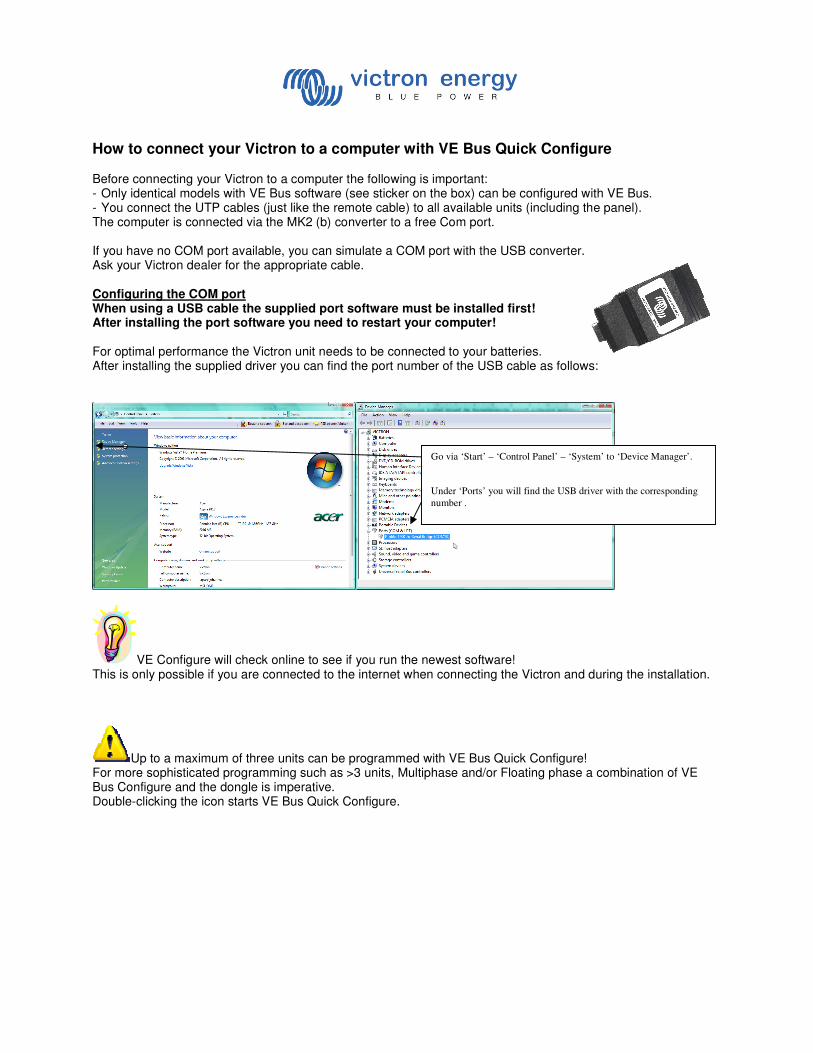
How to connect your Victron to a computer with VE Bus Quick Configure Before connecting your Victron to a computer the following is important: - Only identical models with VE Bus software (see sticker on the box) can be configured with VE Bus. - You connect the UTP cables (just like the remote cable) to all available units (including the panel). The computer is connected via the MK2 (b) converter to a free Com port.
If you have no COM port available, you can simulate a COM port with the USB converter. Ask your Victron dealer for the appropriate cable. Configuring the COM port When using a USB cable the supplied port software must be installed first! After installing the port software you need to restart your computer! For optimal performance the Victron unit needs to be connected to your batteries. After installing the supplied driver you can find the port number of the USB cable as follows:
VE Configure will check online to see if you run the newest software! This is only possible if you are connected to the internet when connecting the Victron and during the installation.
Up to a maximum of three units can be programmed with VE Bus Quick Configure! For more sophisticated programming such as >3 units, Multiphase and/or Floating phase a combination of VE Bus Configure and the dongle is imperative. Double-clicking the icon starts VE Bus Quick Configure.
Go via ‘Start’ – ‘Control Panel’ – ‘System’ to ‘Device Manager’.
Under ‘Ports’ you will find the USB driver with the corresponding
number .
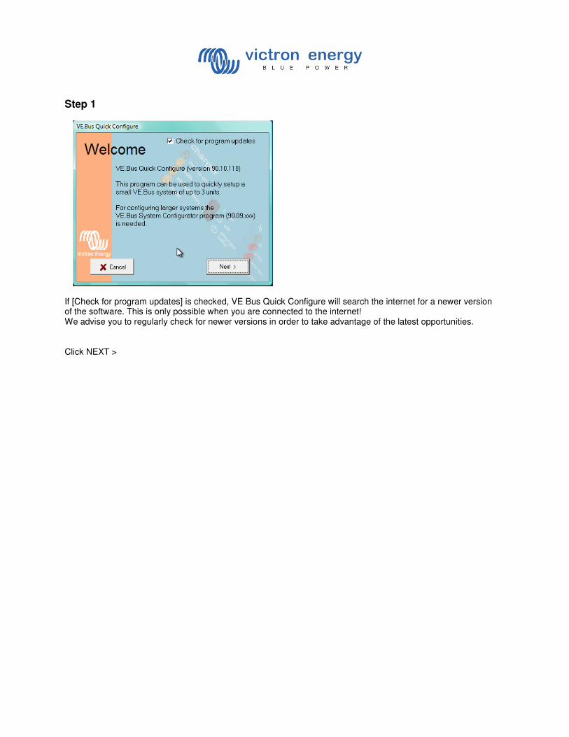
Step 1
If [Check for program updates] is checked, VE Bus Quick Configure will search the internet for a newer version of the software. This is only possible when you are connected to the internet! We advise you to regularly check for newer versions in order to take advantage of the latest opportunities. Click NEXT >
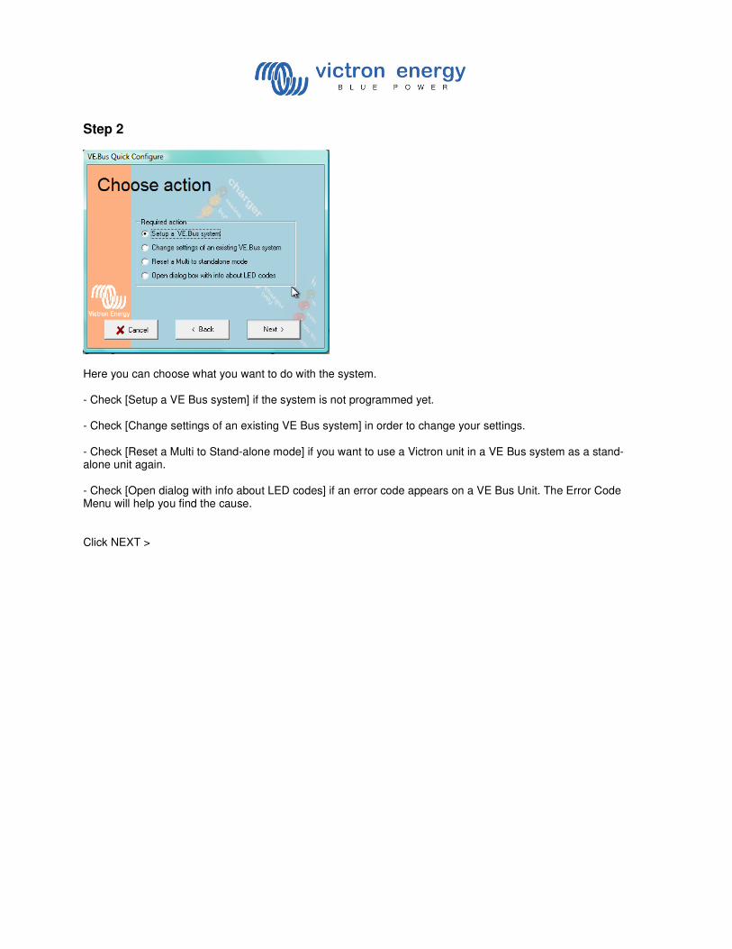
Step 2
Here you can choose what you want to do with the system. - Check [Setup a VE Bus system] if the system is not programmed yet. - Check [Change settings of an existing VE Bus system] in order to change your settings. - Check [Reset a Multi to Stand-alone mode] if you want to use a Victron unit in a VE Bus system as a stand-alone unit again. - Check [Open dialog with info about LED codes] if an error code appears on a VE Bus Unit. The Error Code Menu will help you find the cause. Click NEXT >
Step 3
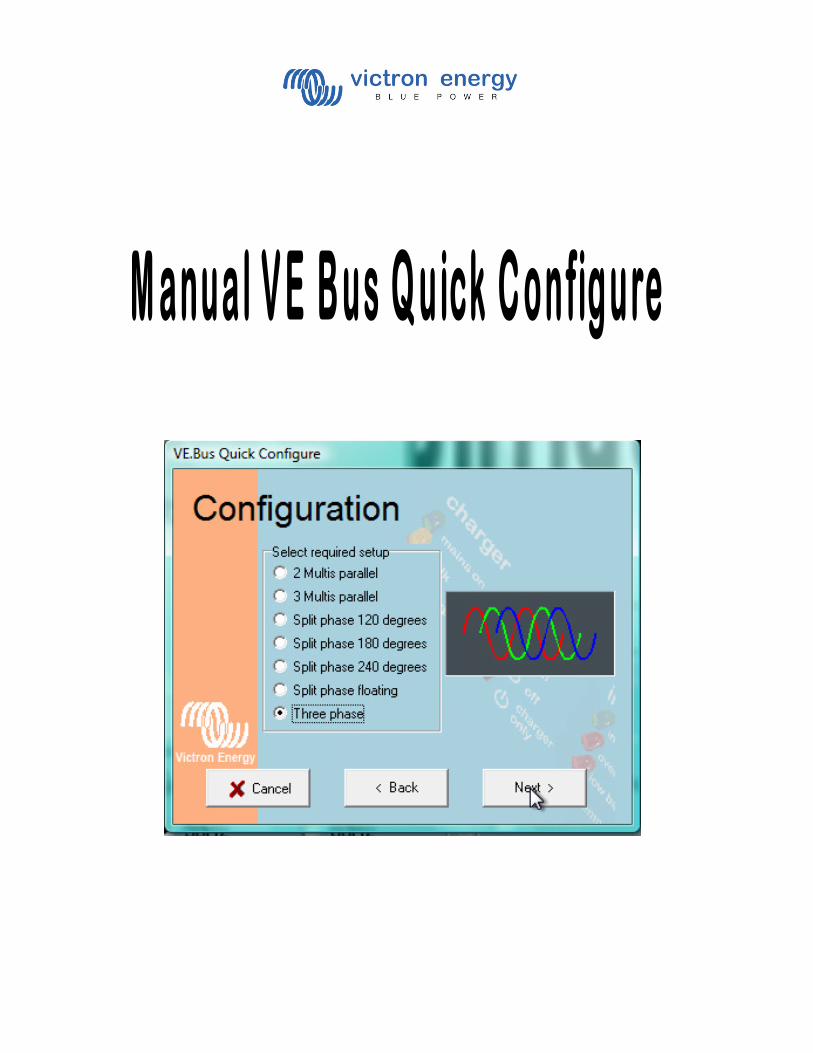
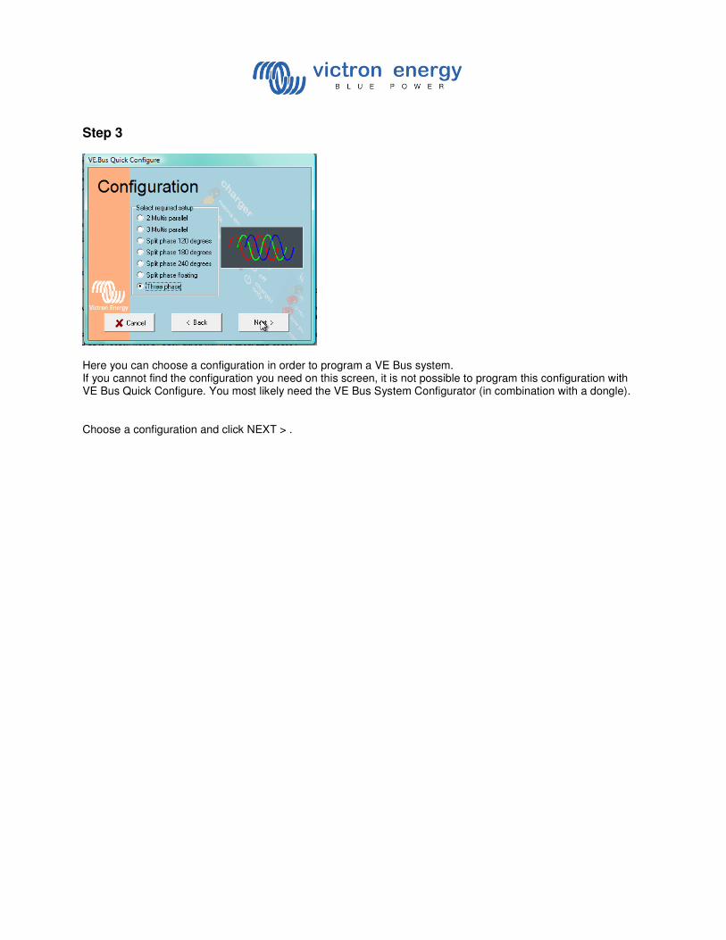
Here you can choose a configuration in order to program a VE Bus system. If you cannot find the configuration you need on this screen, it is not possible to program this configuration with VE Bus Quick Configure. You most likely need the VE Bus System Configurator (in combination with a dongle). Choose a configuration and click NEXT > .
Step 4
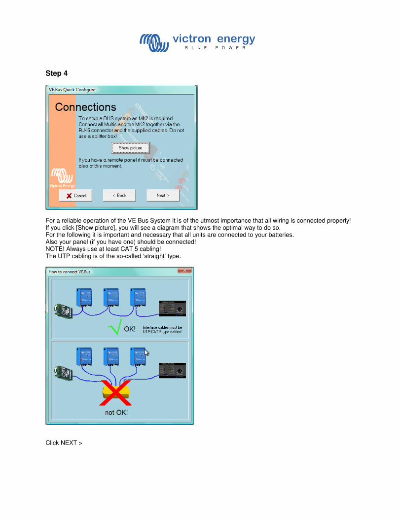
For a reliable operation of the VE Bus System it is of the utmost importance that all wiring is connected properly! If you click [Show picture], you will see a diagram that shows the optimal way to do so. For the following it is important and necessary that all units are connected to your batteries. Also your panel (if you have one) should be connected! NOTE! Always use at least CAT 5 cabling! The UTP cabling is of the so-called ‘straight’ type.
Click NEXT >
Step 5
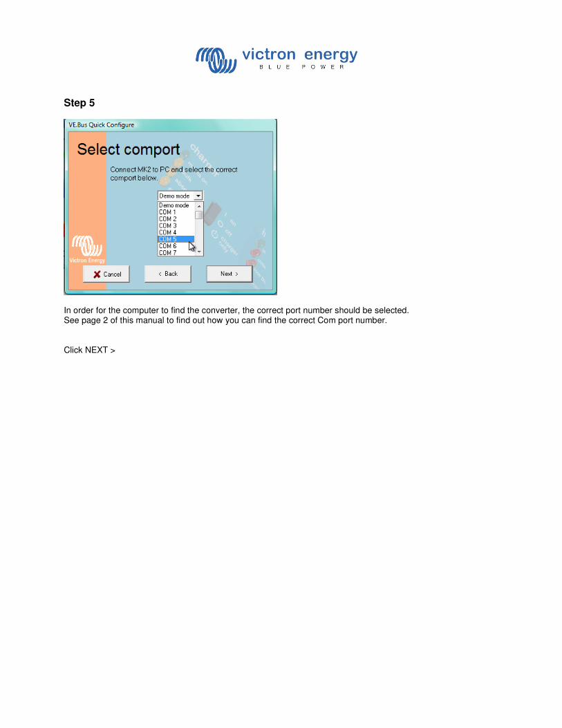
In order for the computer to find the converter, the correct port number should be selected. See page 2 of this manual to find out how you can find the correct Com port number. Click NEXT >
Step 6
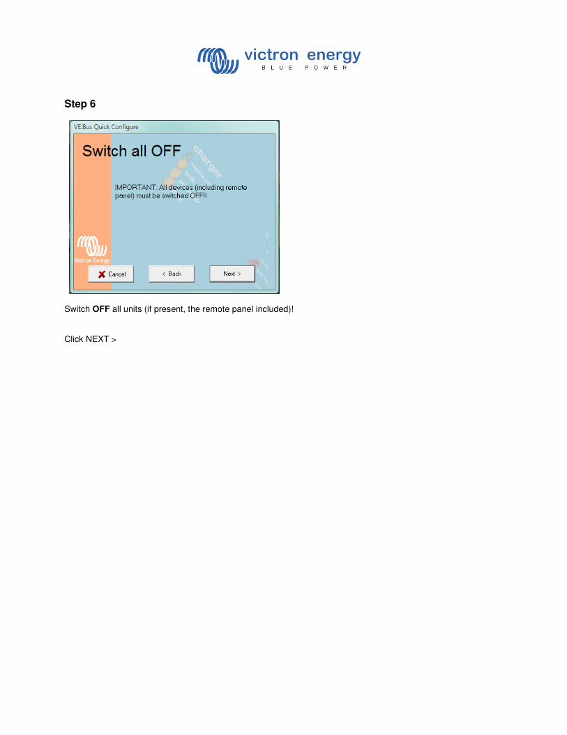
Switch OFF all units (if present, the remote panel included)! Click NEXT >
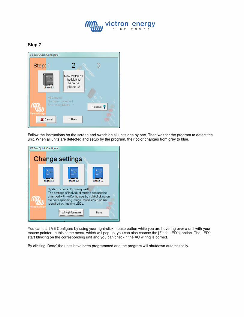
Step 7
Follow the instructions on the screen and switch on all units one by one. Then wait for the program to detect the unit. When all units are detected and setup by the program, their color changes from grey to blue.
You can start VE Configure by using your right-click mouse button while you are hovering over a unit with your mouse pointer. In this same menu, which will pop up, you can also choose the [Flash LED’s] option. The LED’s start blinking on the corresponding unit and you can check if the AC wiring is correct. By clicking ‘Done’ the units have been programmed and the program will shutdown automatically.
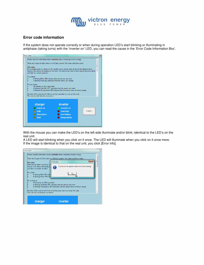
Error code information If the system does not operate correctly or when during operation LED’s start blinking or illuminating in antiphase (taking turns) with the ‘inverter on’ LED, you can read the cause in the ‘Error Code Information Box’.
With the mouse you can make the LED’s on the left side illuminate and/or blink; identical to the LED’s on the real unit. A LED will start blinking when you click on it once. The LED will illuminate when you click on it once more. If the image is identical to that on the real unit, you click [Error info].