map reading and field sketching 1942
DESCRIPTION
LEITURA DE MAPASTRANSCRIPT
MAP READING AND FIELD SKETCHING T h e U s e o f t h e Pro trac tor a n d F i e l d
C o m p a s s a n d R e c o n n a i s s a n c e f o r
B a t t a l i o n I n t e l l i g e n c e
/ WQQiLl
q L C O P Y R I G H x l
Compiled and written by
CAPTAIN A. S. KBIGHLEY, M.C. A.M.F.
Late G.S.O. 3, 4th Div. A.I.F.
Bde. Intelligence Officer, 3rd Bde. A.I.F.
B y t h e S a m e A u t h o r
The Essentials of Training for the
HOME GUARD • Weapons their Potentialities
and Limitations
Attack, Defence and
Guerilla Tactics
OBTAINABLE AT ALL STATIONERS AND BOOKSELLERS
Price : One Shilling
Map Reading and Field Sketching
The Use of the Protractor and Field Compass
and Reconnaisance
for Battalion Intelligence
•
COPYRIGHT 1942
Compiled and written, by
CAPTAIN A. S. KEIGHL.EY, M.C. A.M.F.
La te G-S.O. 3, 4th Div. A.I.F.
Bde. Intelligence Officer, 3rd Bde., A.I.F.
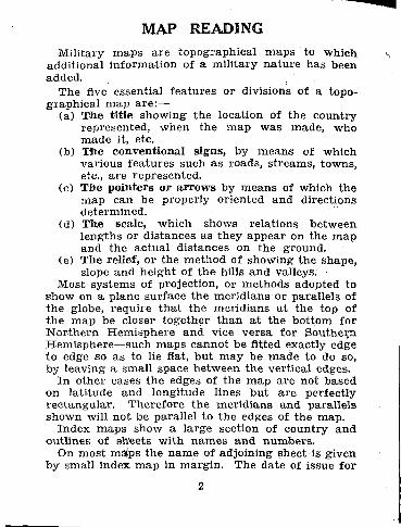
MAP READING Military maps are topographical maps to which
addit ional informat ion of a mili tary na ture has been added.
The five essential fea tures or divisions of a topo-graphical map are:—
(a) Tile tit le showing the location of the country represented, when the m a p was made, who made it, etc.
(b) Tlhe conventional signs, by means of which various fea tures such as roads, s treams, towns, etc., a re represented.
(c) The pointers or a r rows by means of which the m a p can be properly oriented and directions determined.
(d) The scale, which shows relations between lengths or distances as they appear on the m a p and the ac tual distances on the ground.
(e) The relief, or the method of showing the shape, slope and height of t he hills and valleys.
Most systems of projection, or methods adopted to show on a plane surface the meridians or parallels of the globe, require tha t the meridians a t the top of t h e map be closer together t h a n a t the bottom for Northern. Hemisphere and vice versa for Southern Hemisphere—such maps cannot be fitted exactly edge to edge so as to lie flat, but may be made to do so, by leaving a small space between the vertical edges.
In other cases the edges of the map a r e not based on lat i tude and longitude lines bu t a re perfect ly rec tangular . Therefore the meridians and parallels shown will not be parallel to the edges of the map.
Index maps show a large section of country and outlines of sheets with names and numbers .
On most maips the name of adjoining sheet is given by small index m a p in margin. The date of issue fo r
2
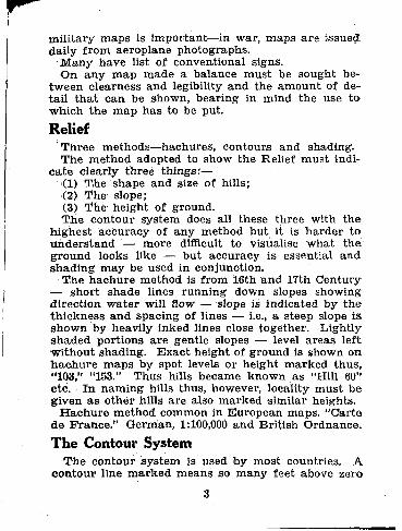
mili tary maps is important—in war, maps a r e issued daily f r o m aeroplane photographs.
M a n y have list of conventional signs. O n any m a p made a balance mus t be sought be-
tween clearness and legibility and the amount of de-ta i l t h a t can be shown, bear ing in mind the use t o •Which the m a p has to be put.
Relief Three methods—hachures, contours and shading. The method adopted to show the Relief mus t indi-
ca t e clearly three things:— (1) T,he shape and size of hills; (2) The slope; (3) The height of ground. The contour system does all these three with t h e
highest accuracy of any method but it is ha rde r to under s t and — more difficult to visualise wha t the ground looks like — but accuracy is essential and shad ing may be used in conjunction.
The hachure method is f rom 16th and 17th Century — shor t shade lines running down slopes showing direction wa te r will flow — slope is indicated by the th ickness and spacing of lines — i.e., a steep slope is shown by heavily inked lines close together. Lightly shaded port ions a re gentle slopes — level a reas lef t wi thout shading. Exac t height of ground is shown on hac-hure maps by spot levels or height marked thus, "103," "153." Thus hills became known as "Hill 60" etc. I n naming hills thus, however, locality mus t be given as o ther hills are also marked similar heights.
H a c h u r e method common in European maps. "Car te de Prance." German, 1:100,000 and Brit ish Ordnance.
The Contour System The contour system is used toy most countries. A
contour line marked means so many feet above zero
3
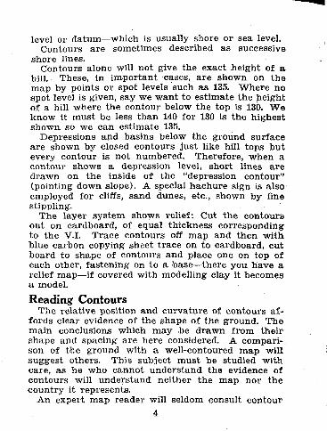
level or datum—which is usually shore or sea level. Contours a re sometimes described as successive
shore lines. Contours alone will not give the exact height of a
hill. These, in impor tant cases, a r e shown on the map by points or spot levels such as 135. Where no spot level is given, say we wan t to es t imate the height of a hill where t he contour below the top is 130. W e know it mus t be less than 140 for 130 is the highest shown so we can es t imate 135.
Depressions and basins below the ground surface a r e shown by closed contours jus t like hill tops but every contour is not numbered. Therefore, when a contour shows a depression level, shor t lines a r e d rawn on the inside of the "depression contour" (pointing down slope). A special hachure sign is also employed for cliffs, s and dunes, etc., shown by fine stippling.
The layer sys tem shows relief: Cut t he contours out on cardboard, of equal thickness corresponding to the V.I. Trace contours off map and then wi th blue carbon copying shset t race on to cardboard, cut board to shape of contours and place one on top of each other, fas ten ing on to a base—there you have a relief map—if covered with modelling clay it becomes a model.
Reading Contours The relative position and curva ture of contours a f -
fords clear evidence of the shape of the ground. The main conclusions which may ,be d rawn f rom their shape and spacing a re here considered. A compari-son of the ground with a well-contoured map will suggest others. This subject m u s t be studied wi th care, as he who cannot unders tand the evidence of contours will unders tand nei ther the m a p nor the country it represents .
An expert map reader will seldom consult contour 4

numbers or spot heights for the general purpose of dist inguishing hill f r om valley, because there is gen-erally clear evidence of the slope of the ground in s t reams , lakes and ponds. A s t ream mus t be in a valley and a lake or pond in a depression. I t is this simple f ac t tha t makes a study of the dra inage the first step in the examination of any map.
Uniform, convex and concave slopes are represent-ed as follows:
i. When the contours are evenly spaced the slope represented is uniform. (The slope of river and s t ream beds is generally uniform except nea r the source).
ii. When the spacing, reading f r o m high to low, decreases the slope is convex. (The top slopes of hills are often, though not always, convex.)
iii. When the spacing, reading f r o m high to low, increases, the slope is concave. (The bottom slopes of hills are generally concave).
Uni form and concave slopes viewed by an observer f r o m above, a re visible throughout ; in o ther words, there a re no concealed portions to f o r m "dead ground," convex slopes, on the other hand, imply dead ground.
Contours d rawn close to each other indicate a steep slope; the f a r t h e r apa r t they are, the more level is t h e ground.
I t is impor tan t to realise not only the capabilities, but also the limitations of contoured maps. A small-scale m a p has no room in which to show the number or the accurate- shape of contours character is t ic of a l a rge r scale. If the V.I. is 50 fee t (as on one-inch maps) , fea tures of real tactical impor tance (but of a lesser height than 50 feet) may not be shown. On quarter- inch maps the V.I. is generally 200 feet, and comparat ively large fea tures a r e not shown.
Horizontal Equivalent (usually wri t ten H.E.) — is the distance in plan between two ad j acen t contours.
5

Vertical In te rva l (usually wri t ten V.I.) — Is the' difference in level between two ad jacent contours.
Slopes and Gradients The slope (rise or fall) of the .ground between a n y
two points may be expressed as a n angle — e.g., 5. degrees — or as a gradient — e.g., 1/15. The s lopes of roads and rai lways a re usually expressed as gradi-ents, or as a rise or fall of so many units in a given distance.
The gradient is the tangent of the angle of slope
( " ) \ H . E . /
and the relationship between slope V.I. and H.E. m a y be founded on the fac t t h a t the tangent of 1 degree* is approximately l /60th (or, when the slope is 1 de-gree the ground rises (or falls) one foot in a distance-of sixty feet.
1 60 feet. Thus a slope of 1/20 feet equals 3 degrees, i.e.—
20 feet One word of caution mus t be added. The V.I. is.
usually expressed in fee t and the H.E. is generally measured in yards, but the rules given above a re only t rue when both a re measured in the same unit.
Examples of Working in Slopes and Gradients A certain M.T. Column, fully loaded, cannot cl imb
gradients steeper than 1/5, and it is required to find f rom the map a practicable road f rom A to B.
A convenient road goes up a hill on which contours (V.I. of 50.feet) are, a t the minimum, 100 yards (®v-300 feet) apar t . W h a t is the gradient?
6
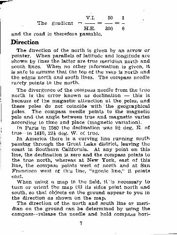
V.I. 50 1 The gradient = = = -
H.E. 300 6 a n d the road is therefore passable.
Direction The direction of the north is given by an ar row or
pointer. When parallels of lati tude and longitude a re shown by lines the la t ter a re t rue meridian nor th and south lines. When no other informat ion is given, it Is s a f e to assume tha t the top of the map is nor th and the edges nor th and south lines. The compass needle rare ly points to the north.
The divergence of the compass needle f r o m the t rue n o r th is the error known as declination — this is because of the magnet ic a t t ract ion a t the poles, and these poles do not coincide with the geographical poles. The compass needle points to the magnet ic pole and the angle between t rue and magnet ic varies according to t ime and place (magnetic variat ion).
In Pa r i s in 1580 the declination was deg. E. of true—in 1810, 22i deg. W. of true.
I n America there is a curving line running south passing through the Great Lake district, leaving the coast in Southern California. At any point on this line, the declination is zero and the compass points to the t rue north, whereas a t New York, east of this line, the compass points west of nor th and a t San Francisco west of this line, "agonic line," it points east .
When using a map in the field, i t is necessary to t u rn or orient the map till its sides point nor th and south, so tha t objects on the ground appear to you in the direction as shown on the map.
The direction of the north and south line or meri-dian on the ground can be determined by using the compass—release the needle and hold compass hori-
7
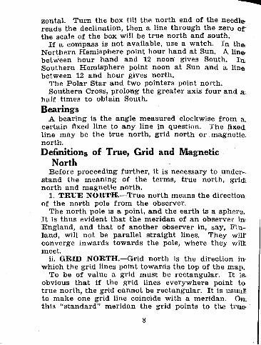
zontal. Tu rn the box till the nor th end of the needle^ reads the declination, then a line through the zero of the scale of the box will be t rue north and south.
If a compass is not available, use a watch. In th& Nor thern Hemisphere point hour hand a t Sun. A line' between hour hand and 12 noon' gives South. l a Southern Hemisphere point noon a t Sun and a line between 12 and hour gives north.
The Polar S ta r and two pointers point north. Southern Cross, prolong the grea ter axis four and a.
half t imes to obtain South. Bearings
A bear ing is the angle measured clockwise f rom a. certain fixed line to any line in question. The fixed line may be the t rue north, grid nor th or magnetic: north. Definitions of True, Grid and Magnetic
North Before proceeding fur ther , it is necessary to under -
s tand the meaning of the terms, t rue north, gridl nor th and magnet ic nor th .
1. T R U E NORTH.—True north means the direction; of the nor th pole f rom the observer.
The north pole is a point, and the ear th is a sphere. I t is thus evident t ha t the mer idan of an observer im England, and tha t of another observer in, say, F in -land, will not be parallel s t ra ight lines. They wilt converge inwards towards the pole, where they will: meet.
ii. GRID NORTH.—Grid nor th is the direction im which the grid lines point towards the top of the map.
To be of value a grid mus t be rectangular . I t is. obvious t h a t if the grid lines everywhere point to t rue north, the grid cannot be rectangular . I t is usual! to make one grid line coincide with a meridan. On-, th is "s tandard" mer idan the grid points to the truer
8

nor th . All other vertical grid lines a re d rawn parallel t o it, and do not point to the t rue north, but in each case to a different and imaginary point called the ;grid nor th .
The angle between grid north and t rue nor th is .known as "the angle of convergence," and it is evi-den t t ha t this angle increases the f a r t h e r the grid d e p a r t s f r om the s t andard mei'idan.
111. MAGNETIC NORTH.—Magnetic nor th is the .direction in which the compass needle points (un-af fec ted by any local a t t rac t ion) ; i.e., the direction of the magnet ic pole a t any point. The magnet ic nor th pole changes f rom year to year, and thus the mag-netic variat ion, which is the angle between t rue nor th and magnet ic north, varies f rom year to year as well as f r o m place to place.
I t should be noted here tha t (a) every ordinary compass h a s its own individual var iat ion which will •differ by a constant amount f rom the local magnet ic variat ion, and Ob) tha t compasses are affected by local a t t ract ion, such as a hill in which magnet ic i ron ore is to be found, guns, tanks, etc. Thus, before us ing a compass for accurate work, certain precau-t ions mus t he taken.
To test the individual variation of the compass proceed as follows:—
1. Iden t i fy on the Map and Ground, the s tandpoint "A" and some dis tant object "B."
2. F r o m map with prot rac tor find Grid (or True) bear ing of "B."
3. Wi th compass, find compass bearing of "B." 4. F r o m the Grid (or True) and Compass Bearings,
find the compass variation. 5. Compare t he compass variat ion with local mag-
netic variat ion. (a) If they coincide, the compass is correct.
9

(b) If different, the compass will have an indivi-dual var iat ion of so many degrees E a s t or West of Magnetic North .
Conversion of Bearings The bear ing of any object on a m a p may be ex-
pressed in one of th ree ways, i.e., with reference to the t rue north, grid nor th or magnetic north. On a gridded m a p all bearings must be given with refer-ence to grid north, and not to t rue or magnet ic north.
Gridded maps show in the margin the angle between grid nor th and magnet ic nor th with a n additional note s ta t ing the angle between the grid nor th and the t rue nor th for t ha t sheet. This enables the user of a m a p to convert a bear ing given with reference to magnet ic or t rue nor th to grid north.
Supposing the variat ion of a compass in a par t icular locality to be 20 degrees West, a magnetic bear ing of 20 degrees will give t rue North . Similarly, if the var ia t ion is 20 degrees East , a magnet ic bear ing of 340 deg. (360 minus 20) will give t ru th North . I t will therefore be seen t h a t when the variat ion is West it mus t be deducted f rom, and when the var ia t ion is. Eas t it mus t be added to the magnet ic bearing in order to give the t rue bearing. I t will also be seen tha t when grid Nor th is west of t rue Nor th the differ-ence mus t be added to, and when the grid Nor th is east of t rue Nor th the difference mus t be subt rac ted f rom the t rue bear ing to give the grid bearing. If these rules are followed, conversion presents no diffi-culty, but it is essential to draw a rough d iagram t o prevent errors of sign being introduced.
Scales There are 63,360 inches to the mile. Scales on maps in the U.K., India, Canada, and'
Austral ia are usually expressed in words showing re-
10

lat ions between inches on the map and miles or yards •on the ground—
1 or 1 inch to 1 mile.
63,360 The f rac t ion in each case is called the Representa-
tive Frac t ion or R.P., and means one uni t on t h e m a p (numera to r ) represents a certain number of miles on t h e ground (denominator) .
To find the number of English miles to the inch in .any m a p t h a t has a n R.F., divide the denominator of the R.F. by 63,360; this gives the number of miles to •the inch.
1 15,840 Thus if the R.F. is , then = .25 miles
15,840 63,360 o n the ground to one inch on the map.
To find the number of inches to the mile then, re-verse and divide 63,360 by the nominator of the R.F.
1 63,360 Thus if the R.F. is , then = 4 inches
15,840 15,840 •to the mile.
A scale should be about six inches long. The sizt depends on the object fo r which the scale is made Reconnaissance sketches of an a rea to explain a plaJi of a t t ack or to show lines of advance, of a road or a r iver, or of a defensive or outpost position, a r e usu-a l ly made to the scale of 1 to 4 inches to the mile.
Scale to show yards on a map, 4 inches to the mils 1 2,000 x. 36
= . Say you wan t 2,000 yards, then 15,840 15,840
= 4.54 inches, length of scale required. If you w a n t to show yards on a map, two inches to
11

1 the mile, or when the number of ya rds is 8,000
31,680 5,000 x 36
then = 5-68 inches required. 32,680
1 (a) Scale 1 inch to mile six inches divide into
63,360 six miles and one mile on lef t of scale into quar ters , or 5.1 inches showing 9,000 yards divided into 1,000 yards.
1 (b) Scale 1 inch to 2 miles wanted seal®
126,720 for body of troops march ing three miles per houv.
Scale of six inches equals 12 miles. Divide in to four sections each equalling three miles or one hour 's march. Subdivide lef t division into twelve pa r t s each equalling 5 minutes march .
To construct a scale for paces on a map, one over 15,840 (four inches to the mile) six inches would show Is miles or 2,640 yards. Assuming the pace to be equal to 30 inches, this would equal 3,168 paces, there-fore you would t ake 3,000 paces as the length of the scale.
3,000 x 30 = 5.68 inches, length of scale required.
15,840
MAP REFERENCES The Modified British System
To describe any position or point on a, map the. numbered grid lines must be read, first f r om West to Eas t and then f rom South to North, and the square in which the point is s i tuated mus t be mental ly fur-
12
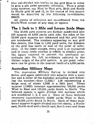
t he r sub-divided into tenths on the grid lines in order to give a pin point accurate reference. Thus a point lying between, say West to Eas t grid, 23-24 and South to Nor th grid 10 and 11, in the centre of this square would be described by the following co-ordinates, 235105.
All points of reference are co-ordinated f rom t h e South-West corner of any map or square.
The 1 Inch to 1 Mile) and Larger Scale Maps The 10,000 yard squares are f u r t h e r subdivided into
100 squares of 1,000 yards each side; the sides of the 10,000 yard squares are thickened and the grid lines a r e numbered. The numbers appear ing on any grid line denote, this t ime in 1,000 ya rd units, the distance of the grid line north or east of the point of refer-ence. In the sheet margin, every grid is so numbered and to every tenth number is added, in smaller print , the f igure required to convert the shortened co-ordinate into the full co-ordinate r e f e r r ed to t he (false) origin of the grid system. A pin point refer-ence can be given to the nearest t en th of a 1,000 yards.
Australian Military Maps The Austra l ian Military Survey is divided into
zones, and again subdivided into squares with a num-ber and a let ter of the alphabet preceding and follow-ing the number—thus (1.56H.) 1.56 represent ing a la rge a r ea of which 1.56H is a 24th part . These squares (1.56H) measure approximately 100,000 y a r d s Wes t to E a s t and 120,000 yards South to North . T h e let tered square is again divided into sections which a r e numbered 1, 2, 3 and 4. Each of these sections measures approximately 50,000 yards West to E a s t , and 60,000 yards South to North . E a c h of these num-bered squares is again divided into two sheets, a North-east, North-west and a South-east, South-west and these
13
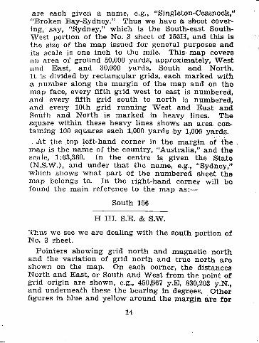
are each given a name, e.g., "Singleton-Cessnock," "Broken Bay-Sydney." Thus we have a sheet cover-ing, say, "Sydney," which is the South-east South-w e s t portion of the No. 3 sheet of 156H, and this is the size of the map issued for genera] purposes and i ts scale is one inch to the mile. This- m a p covers an a rea of ground 50,000 yards, approximately, Wes t a n d East , and 30,000 yards, South and North. I t is divided by rec tangular grids, each marked wi th a number along the marg in of the map and on the m a p face, every fifth grid west to east is numbered, a n d every fifth grid south to nor th is numbered, a n d every 10th grid running West and E a s t and South and Nor th is marked in heavy lines. The square within these heavy lines shows an a r ea con-taining 100 squares each 1,000 yards by 1,000 yards.
A t the top lef t-hand corner in the marg in of the m a p is the name of the country, "Australia," and the scale, 1:63,360. I n the centre is given the State (N.S.W.), and under tha t the name, e.g., "Sydney," which shows w h a t pa r t of the numbered sheet t he m a p belongs to. In the r ight-hand corner will be found the main reference to the map as:—
South 156
H III. S.E. & S.W.
Thus we see we a re dealing wi th the south portion of No. 3 sheet.
Pointers showing grid nor th and magnet ic nor th and the variat ion of grid nor th and t rue nor th a r e shown on the map. On each corner, the distances Nor th and Eas t , or South and West f r o m the point of grid origin a re shown, e.g., 450$67 y.E, 830,203 y.N., and undernea th these the bear ing in degrees. Other figures in blue and yellow around the marg in a re fo r
14
t
art i l lery use only. At the bot tom of the m a p is given a char t showing how to give a pin point reference as explained before. The immediately ad jacen t sheets are shown in the margin and the ad jacen t sheets over a wide area are given in the index on the cover.
The scale shown on the map is a six inch scale divided into six miles, and a 9,000 yard scale measur-ing 5.1 inohes, showing divisions of 1,000 yards wi th the secondaries down to 100 yards. The Vert ical interval of the contours is also shown in feet, and along the bottom of the margin are shown the con-ventional signs used on the map. In giving a map reference on this scale, it can be given to within a n a rea of 100 yards. Fo r example, t ak ing the Sydney Observatory as a point fo r reference, the grid m a p reference would be Sheet 1.56H I I I S.E. & S.W. or "Sydney" 207,168.
VISIBILITY I t is of ten of importance to discover f rom the m a p
whether two points a re mutual ly visible. On open ground where there a re no trees, hedges, buildings, etc., one point is visible f rom another so long as the ground does not rise above the line which joins them. Thus, if the country between two points is level, slopes evenly, is concave, or lower than both of them, they will be intervisible. But, where a hill or a con-vex slope intervenes, one point will not be visible f r o m the other.
Visibility problems can be answered by inspection of a contour m a p or sketch in most cases. But there m a y be a doubt. For example, a hill between two points may be higher than one of them, but if it does not rise above the line joining them they will Still be intervisible. A quick method of finding whether this is so is as follows:—
To find whether two points A and C are intervisible draw a line joining them, and on t h a t line note any
15
point likely to in terfere wi th the line of sight be-tween A and C and est imate its height. Suppose there is a point B the height of which is 260 feet, and suppose t he height of A is 300 feet , and t h a t of C 200 feet. Measure up on the m a p the distances A to B and A to C, suppose A-B is 1,200 yards and A-C is 2,700 yards.
1 The slope A-B drops 40 fee t in 1,200 ya rds or —.
90 1
The slope A-C drops 100 feet in 2,700 yards or —. 81
This shows t h a t the slope A-C is steeper t h a n slope A-B, and therefore B will obstruct the view.
Another method by simple proportion sum is a s follows:—
Suppose distance A to D, 700 yarsd A to E, 1,520 yards
Difference in height A and D, 50 feet. Difference in height A and E, 75 feet .
The line of sight f r om A to E rises 75 feet in 1,520 yards. The amoun t it will rise in 700 yards is found by proportion to be 34.5 feet. I t therefore passes 15 feet below the summit of D and E will not be visible f rom A.
Another method is by drawing a section. This however, requires time, bu t it has t he advan tage t h a t dead ground is clearly shown.
The extent to which visibility problems can be Solved f rom the map, depends on the size of the V.I. If the V.I. is small, the unrepresented ground fea tu res a re small, and visibility can be determined wi th some accuracy, but if the V.I. is large the reverse is t he case. The unrepresented ground fea tures a re large. Visibility therefore should seldom be assumed with-out inspection of the ground.
16

P r o m the foregoing the following rules c a n b e fo rmula ted :—
i. If the m a p or ske tch shows two points on t he op-posite sides of a valley s tanding well above a n y intervening ground, these will be intervisible.
ii. I f , between any two points, a f ea tu re is repre-sented higher t h a n both, the points .will no t be intervisible.
iii. If , between any two points, a f e a t u r e is repre-sented higher t h a n one of t he points, the points may, or may not, be intervisible.
iv. When a slope is shown by the map to be convex, two points thereon will not be intervisible.
V. When a slope is shown by the m a p to be concave, two points thereon will probably be intervisible.
vi . When ground is shown by the m a p to be level, the intervisibility of two points will depend en-tirely upon the absence or presence of such ob-jects as houses or trees. t
A visibility diagram showing points visible and in-visible f r o m an observation post c a n be drawn. To •construct this, identify the observation post and a re-fe rence object on the map. D r a w a line between these and m a r k it zero. Set off lines a t 10 degrees interval radia t ing on either side of zero line. Study the features , m a r k on the m a p the objects and fea-tures which in terfere wi th the view f r o m the obser-ver's position and shade these in. By this means a d i a g r a m showing no more t h a n grid lines invisible a r ea s and zero line can be drawn which suffice a s a ,guide for use on any map of the s a m e scale and copies can be taken f r o m it.
SECTIONS Section drawing is seldom necessary in practice. I t
Is explained because under cer ta in c i rcumstances it may be a useful method of finding the extent of dead ground, or of ascertaining whether one point is vis-ible f r o m another point.
17

A section has been defined as " the outline of t h e intersection of the ground by a vert ical plane"; a. rai lway cut t ing affords a good il lustration of a sec-tion. Another good illustration is a cottage loaf of bread cut in half f r o m top to bottom, fo r the outline seen when one-half of the loaf is removed is a full-sized section of the loaf. A knowledge of the con-tours and of the V.I., enables us to d raw a section of a hill which will present a fa i r ly accura te picture of t he slopes as they would appear if a cutt ing were m a d e r ight th rough tha t hill.
I t is d rawn as follows:— On the m a p d raw any s t ra ight line through the
port ion of the hill of which a section is required. M a r k on this line the points a t which the contours intersect it. Then on ano ther piece of paper, d raw a. horizontal line of equal length to represent the level of the lowest contour and m a r k on it the contour intersections. F r o m each of these points draw a perpendicular line and m a r k on the r ight and the lef t of the upr ights equidistant points representing t he V.I. of the map. Through these points draw lines: parallel to the lowest line and m a r k these lines corre-sponding to the heights of the contours they repre-sent. Then d r a w your section ascending f rom the-bo t tom to the top through the points where the per-pendicular lines cut the horizontal lines.
SETTING A MAP A N D FINDING A POSITION ON IT
To set or "orient" a map, lay it out to correspond wi th the ground directing the t r u e nor th point on the-m a p to the north. When this is done it will be seen tf iat the fea tu res on the ground will be shown in t he same direction as they are shown on the map. A m a p can be set by c o m p a s | by tak ing the bearings of '
18
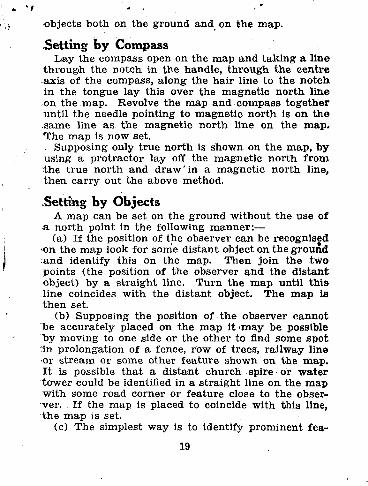
objects both on the ground and on the map.
.Setting by Compass L a y the compass open on the map and tak ing a l ine
t h r o u g h the notch in the handle, t h rough the cent re axis of the compass, a long the hair l ine to the no tch in the tongue lay this over the magnet ic no r th l ine on the map. Revolve the map and compass together unt i l the needle pointing to magnet ic nor th is on t he same line as the magnet ic nor th line on the map . T h e m a p is now set.
Supposing only t rue nor th is shown on the map, by using a prot rac tor lay off the magnet ic nor th f r o m the t rue nor th and d r a w ' i n a magnet ic no r th line, then car ry out the above method.
Setting by Objects A map can be set on the ground without t he use of
a no r th point in the following manner :— (a) If the position of the observer can be recognised
•on the m a p look for some dis tant object on the ground a n d identify this on the map. Then join the two points ( the position of the observer and the d is tant object) by a s t ra ight line. T u r n the m a p unti l t h i s line coincides wi th the dis tant object. The m a p is t h e n set.
(b) Supposing the position of the observer cannot be accurate ly placed on the m a p it 'may be possible by moving to one side or the other to find some spot nn prolongation of a fence, row of trees, ra i lway line or s t ream or some other f ea tu re shown on the map. I t is possible t h a t a d is tant church spire or wa t e r tower could be identified in a s t ra igh t line on the m a p wi th some road corner or f ea tu re close to t he obser-ver. If the map is placed to coincide with this line, t h e m a p is set.
(c) The simplest way is to identify prominent fea-
19
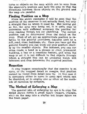
tu res or objects on the map which can be seen f r o m the observer 's position and hold t he m a p so t h a t t h e directions between these objects on t he ground a n d the m a p a re parallel. Finding Position on a Map
F r o m the above examples it will be seen that t h e position of the observer is not actually fixed, bu t only a s t ra ight line on which it mus t lie. But having got so far , the m a p now being set, it is quite easy t o determine with sufficient accuracy the position f o r m a p reading though not fo r sketching. The correct position can be determined f r o m the detail on t he map. F i r s t of all, get an approximate position in re-lation to the general prominent fea tures such as a hill, road, river, buildings, etc. Once you have got t h e general locality you can work out your position exact-ly by the smaller objects. F o r instance, you can use cross roads, a bend in a s t ream or river, p rominent building, a bay or a coastline fea ture , and when t h e m a p is set it is not difficult to find objects through which a s t ra ight line can be produced which will intersect and thus determine the required position.
Resection I t may happen occasionally that the country is so
open, or the mapped detail so meagre, t ha t position, cannot be found f r o m detail n e a r by. In this case it is necessary either to move to some spot which can. be identified, or to employ one or other of the meth-ods of resection by compass.
The Method of! Enlarging a Map The general idea of enlarging by eye is to copy t h e
detail shown inside a small figure (square, t r iangle , etc.) on the m a p into a similar but la rger figure on the f r e sh paper.
20
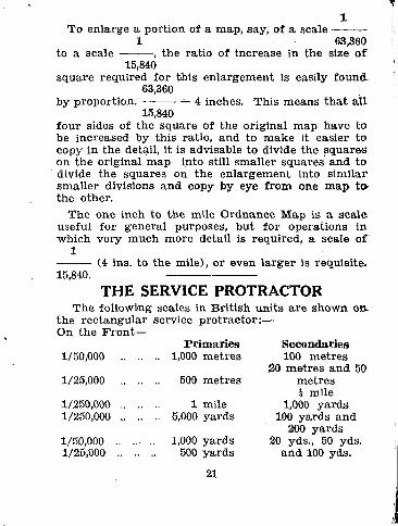
1 To enlarge a portion of a ma.p, say, of a scale
1 63,360 to a scale , the ratio of increase in the size of
15,840 square required for this enlargement is easily found.
63,360 by proportion. = 4 inches. This means t h a t a l l
15,840 f o u r sides of the square of the original map have to be increased by this ratio, and to m a k e it easier to copy in the detail, it is advisable to divide the squares on the original m a p into still smal ler squares and to divide the squares on the enlargement into s imilar smaller divisions and copy by eye f r o m one m a p to the other.
The one inch to the mile Ordnance Map is a scale useful fo r general purposes, bu t for operations in which very much more detail is required, a scale of
1 (4 ins. to the mile), or even la rger is requisite.
15,840. THE SERVICE PROTRACTOR
The following scales in Brit ish uni ts a re shown on-the rec tangular service protractor :— On the Front—
Pr imar ies Secondaries 1/50,000 1,000 met res 100 met res
20 met res and 50 1/25,000 500 metres metres
i mile 1/250,000 1 mile 1,000 ya rds 1/250,000 5,000 yards 100 yards and
200 yards 1/50,000 .. .. .. 1,000 yards 20 yds., 50 yds. 1/25,000 500 yards and 100 yds.
21
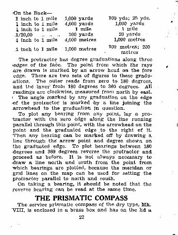
O n the Back— 1 inch to 1 mile 1 inch to 1 mile i inch to 1 mile 1/20,00 1 inch to 1 mile
1 inch to 1 mile
1,000 yards 4,000 yards
1 mile 100 yards
4,000 metres
1,000 met res
100 yds; 25 yds. 1,000 yards
1 mile 20 yards
1,000 metres 100 metres ; 250
metres The pro t rac tor has degree graduat ions along three
•edges of the face. The point f r om which the rays a r e drawn is ma rked by an a r row head on the fore edge. There a re two sets of figures to these gradu-a t ions . The outer reads f rom zero to 180 degrees, ;anid the inner f r o m 180 degrees to 360 degrees. All readings a re clockwise, measured f rom north by east, i The angle marked by any graduat ion on the edge •of the prot rac tor is marked toy a line joining the a r rowhead to the graduat ion in question.
To plot any bearing f r o m any point, lay a pro-t r a c t o r with the zero edge along the line running parallel th rough this point, with the ar rowhead on the point and the g radua ted edge to the r ight of it. Then any bear ing can be marked off by drawing a line th rough the a r row point and degree shown on t h e g radua ted edge. To plot bearings between 180 degrees and 360 degrees reverse the pro t rac tor and proceed as before. I t is not always necessary to •draw a line nor th and south f r o m the point f r o m "which bearings are plotted, because the mer idan or grid lines on the m a p can be used for set t ing the p ro t r ac to r parallel to nor th and south.
On t ak ing a bearing, it should be noted tha t the xeverse bea-ring can be read a t the same time.
THE PRISMATIC COMPASS The service pr ismatic compass of the dry type, Mk.
"VIII, is enclosed in a brass box and has on the lid a 22
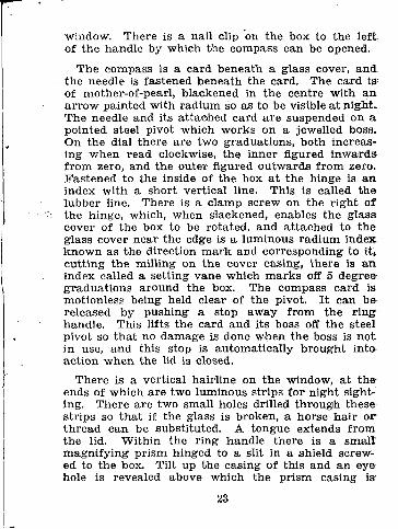
window. There is a nail clip on the box to the l e f t of the handle by which the compass can be opened.
The compass is a card beneath a glass cover, a n d the needle is fastened beneath the card. The card is;
of mother-of-pearl, blackened in the centre with a n a r r o w painted with rad ium so as to be visible a t night* The needle and its a t tached card a re suspended on a pointed steel pivot which works on a jewelled boss. On the dial there are two graduations, both increas-ing when read clockwise, the inner figured i nwards f r o m zero, and the outer figured outwards f r o m zero. Fas tened to the inside of the box a t the hinge is an index wi th a short vertical line. This is called t he lubber line. There is a clamp screw on the r ight of the hinge, which, when slackened, enables the glass cover of the box to be rotated, and a t tached to t he glass cover near the edge is a luminous r ad ium index known as the direction mark and corresponding to it, cut t ing the milling on the cover casing, there is an index called a set t ing vane which m a r k s off 5 degree graduat ions around the box. The compass card is motionless being held clear of the pivot. I t can be released by pushing a stop away f rom the r ing handle. This l if ts the card and its boss off the steel pivot so tha t no damage is done when the boss is no t in use, and this stop is automatical ly b rought into-action, when the lid is closed.
There is a vertical hairline on the window, a t the-ends of which a re two luminous strips for n ight sight-ing. There are two small holes drilled through these s t r ips so t h a t if the glass is broken, a horse hai r o r th read can be substi tuted. A tongue extends f rom the lid. Within the r ing handle there is a small' magni fy ing prism hinged to a slit in a shield screw-ed to the box. Tilt up the casing of this and an eye hole is revealed above which the prism casing is:
23

Blotted. When the ha i r line is vertical, the edges of this sighting slot should be seen as parallel to it. F o r focussing with the magnifier it is necessary to d raw up the prism. •Observing with the Compass
To make a n observation wi th the prism, pu t the le f t t h u m b through the r ing and the le f t forefinger under-nea th the box. The r ight forefinger should be on the t i n y s tud which is found to the le f t of the hinge. T h i s regulates the spring which steadies the swing of the needle. The hai r line mus t be vertical. Look through the s ight ing slot, keep it vertical with the •object to be sighted and, a t the same time, read the card. If the hand is s teady the bearing can be read !to a quar te r of a degree.
F o r use a t night, t u rn the glass cover until the set-t i n g vane is over the bearing on the outside gradua-t ion of the box, then screw and clamp the cover a t this bear ing and then direct the axis towards the object. I t will then be seen t h a t the direction m a r k and the a r rowhead coincide. The compass is then set fo r n ight march ing on this par t icular bearing.
T o March to this Bearing at Night The direction m a r k and ar rowhead mus t coincide,
and the movement mus t be made in the direction of the hai r line and the luminous patches on the cover. You will then be march ing on the bear ing indicated by the set t ing vane. The rubber on the bot tom of the cover is to prevent the compass f rom slipping. •
Compass Errors The compass is affected by the presence of iro.n,
heavy guns, te legraph wires, barbed wires, dumps, t ractors , i ron huts, etc. All the surface disturbing elements can be avoided, but those underground can-not be detected except by a n error in the compass, bu t
24
when there is this slightest sign of disturbance, i f the compass is shifted, unless there is some wide magnetic field, this difficulty can be got over. Every ordinary compass has its individual error and there-fore all compass users should test their compass on. t rue bearings such as t r igonometry points. Bearings, can be t aken also by a circular pro t rac tor on a large scale map.
Night Marching Nigh t marching requires long practice and care. A
slight knowledge of elementary as t ronomy is useful. The line of luminous patches in the lid ful ly extend-ed will indicate the line of advance, bu t it is always^ wise to try and pick up f r o m the compass bear ing some point or object which can be seen in the da rk to march on. When no object or s tar is available a3 guide, a white pa tch sewn on the back of a guide who« will be sent forward by stages and halted when indis-t inguishable will simplify the correct movement on a bear ing.
RECONNAISSANCE REPORT The value of a report is enhanced if accompanied
by a map, sketch, drawing or photograph. B u t these m u s t only be used to make the subject m a t t e r clear-er to the reader and to decrease the wri t ten word.
Before proceeding on a reconnaissance the best available m a p mus t be procured and in one's own-ter r i tory all topographical information should be gathered f rom local council adminis trat ive maps, etc. A report should include details of the na ture of all f ea tu res which may affect operations, movements, supplies. Included in it should be seasonal weather1
effects, such as floods or droughts, and par t icu lar a t -tent ion paid to the classification of all roads. From, a geological point of view the na ture of the soil and' i ts conditions in wet periods, rocks and broken coun-
25
t r y which would m a k e it difficult f o r aeroplane land-ing, places where wate r m a y be had by boring, de-posits of stone or metal fo r road mending. Most of this informat ion can be procured f r o m the local in-h a b i t a n t s in advance. Maps a re never perfec t even Where there a re large scale maps a great deal of de-tail h a s to be added to bring them "up-to-date and to m a k e them of any value f r o m a mili tary point of view. Do not hesi tate to m a k e a n enlargement of a .given area, adding to it any detail or informat ion relevant to the report to be prepared.
Drawings and Sketching A panorama drawn f rom a n observation post is of
•great value. I t need not be an art is t ic drawing, but practice is necessary to obtain clarity. The following rules will aid:—
i. A considerable portion of t ime should be spent by studying the ground by eye and field glasses.
ii. The perspective must be t aken into account. Objects f a r away appear to be smaller, and mus t be so represented on the drawing. Roads, railway lines, represented by parallel lines appear to mee t a t a van ish ing point on the horizon.
iii. All buildings, trees, na tu ra l fea tures should be d r a w n in outline only in order to convey the impres-sion of shape. Any wooded a reas may be slightly •"hatched."
iv. Simplicity is the basis of a drawing and firm continuous lines mus t be used throughout .
Before commencing a drawing, decide how m u c h is to be included. Military panoramas are, as a rule, i imited to a 30 degrees of arc. If the service pro-t r a c t o r is held horizontally eleven inches f r o m the eye, it covers an angle of approximately 25 degrees.
26
Framework D r a w a mean horizontal line along the horizon a n d
th rough the centre draw a vertical line f rom the ob-server as the central axis of sight. F ix all outs tand-ing points and prominent objects in their correct positions. By using the prot rac tor and the g radua ted edges, it can be observed wha t graduat ion coincides "with the object to be drawn and the position of these can be marked on the paper by laying the p ro t rac to r . on the drawing and mark ing them off. Vertical dis-t ances can he obtained by using the pro t rac tor with t he long side vertical. Thus any point can be accur-ately plotted on the drawing. When this is done, o ther detail can be fitted in by eye or f u r t h e r mea-surement . Sketch the whole in, lightly a t first, t hen thoroughly examine the sketch and compare it wi th t he a rea it represents seeing t h a t no detail is omitted, t hen complete the sketch by drawing in with f u r t h e r lines, th ick in the foreground and th inner as they recede into the distance. All outs tanding points should be marked by a vertical line running to the top of the drawing, their map location given, the i r description and their bear ing wri t ten in block let ters a t the top of the vertical line. When the drawing is complete, the following information mus t be added, in addition to above:—
ii The position of the observation post by m a p re-ference, the bearing of the centre of the sketch f r o m the observation post.
ii. The name, rank, and regiment of the observer. iii. The date, the t ime and the wea the r conditions. iv. Any indication of our own or enemy troops in
the usual conventional sign, blue or red.
Small Sketches Small sketches can be used to i l lustrate details.
27
:such as bridges, fords, -watering points, road detours, etc. Where there a re difficult t u r n s th rough built-up areas, a small sketch with m a p reference and des-cription showing an a r rowhead for change of direc-t ion -will be of grea t value. These little sketches must be prepared in the s ame way as the panorama—main details first and in correct position distance.
'Reads Most informat ion required about roads can be
shown on a m a p and roads should be classifid wi th regard to width, su r face and foundation. An A Class road, wide enough to take two s t reams of traffic.
B Class road wide enough to t ake one s t r e a m of traffic with a n occasional vehicle passing in the s t ream. C Class road only wide enough for one s t r eam of traffic.
These A, B and C Class roads should again be •divided into different categories.
A No. 1 road capable of t ak ing three ton lorries, heavy guns, etc.
No. 2 road capable of t ak ing light cars and one ton lorries.
No. 3 road fit only for horse t ranspor t . No. i notfit for any vehicles.
T h u s we have a road described as A 1, 2, 3 or 4, etc. The su r face of a road deteriorates in wet weather , therefore classify this. Also mention the type of metall ing employed and wha t wear ing it will s tand up to, also mention where the nearest supply of road metal fo r mending purposes is available.
Military Bridges i. Light Bridges (a) Foot Bridges, Inf. in single file;
(b) P a c k bridges, Inf. in file pack animals, etc.
28
ii. Medium Bridge. Inf . in column, motor cars, a rmoured ears, l ight and med-ium artillery, 3-ton lorries and all M.T. up to 5i tons axle load, also t rack vehicles to 8 tons, t r ack not to exceed 8 foot 9 inches.
iii. Heavy Bridges. Heavy artillery, t rac tors , M.T. to 16 tons axle load t anks up to 18 tons.
iv. Superheavy Bridges. Axle loads and t anks in excess of above.
A guard should be posted to control traffic and check unauthorised weights. Notices should be posted Showing traffic allowed. Traffic over bridge generally slow.
Fords • The following a re the fordable depths:—
Cavalry—4 feet. Infantry—3 feet. Tanks—i feet. Light Artillery—2 feet 6 inches. Dragons—2 feet 6 inches. Lorries—2 feet. Motor Cars—1 foot 6 inches. Motor cycles—1 foot.
Good bottoms a re essential for heavy traffic. Sandy bottoms get st irred up and depth increases. I n the s traight pa r t of a river the depth is uni form, generally g rea te r a t a concave bank and less a t a convex bank and when a river is not fordable s traight across, a passable slanting course can of ten be found between two bends.
All fords should be clearly marked, pickets should be driven in above and below a ford, their heads con-
29
nected by s t rong rope and the marks on the pickets, should show three and fou r fee t above the bottom, to m a r k the rise of the water .
The velocity of a r iver can be found by th rowing a piece of wood well out into the s t r eam and measur -ing—and t iming it over a given number of feet . The-m e a n velocity equals 4-5ths of the su r face velocity,, and 7/8ths of the m e a n velocity in fee t per second equals the number of miles per hour.
To get the yield of a s t ream select some 15 y a r d s of fa i r ly uni form channel, t a k e the bread th and aver-age depth in fee t a t several places, get the su r f ace velocity as shown above, t h e n multiply the m e a n velocity by sectional a rea , this will give yield p e r second in cubic feet .
One cubic foot equals six and a quar te r gallons and one gallon weighs 10 lbs.
Daily average man, dr inking and cooking 1 gallon. I n a s tanding camp, average for m a n 5 gallons,
fo r horse or camel 10 gallons. :
RANGE CARDS Attack
i. K a n g e s to be t a k e n in direct line of advance. ii. D r a w parallel lines and fill in s ta r t ing point a n d
objective. iii. T a k e range t o objective and wri te in r ight-hand
column, select some object half-way to objective and enter range in r ight-hand column.
iv. Select and t ake r anges to other intermediate objects, those easily recognised when reached and which appear to be nea r probable fire pos-itions. •
30

v. Simple subtract ion will give you range for each successive object to objective. E n t e r these in left-.hand column and s t r ike out r ight-hand column.
Yards Yards 0 Objective (described) 1,700
100 Small wood 1,600 700 Ruined F a r m 1,000 900 Mound with bush 800
1,300 Line of poplars 400 1,700 Star t ing point (described) 0
Defence i. Mark off on card positions f rom which range is
taken . ii. Describe position accurately. . ill. Select an unmistakable object a n d draw a
thick set t ing ray to it.
iv. Draw these semi-cifcles representing 600, 1,000, 1,500 yards respectively. This caii be conveni-ently drawn with a circular protractor .
vi. Select objects to range on, e.g., positions which enemy may occupy or have to pass, obstacles, bridges, gaps in fences, etc.
•vi. Keeping card on sett ing ray, d raw rays to show direction of objects and of lengths corre-sponding to distances.
vii. Wri te shor t description of each object in block lettering or d raw signs.
viii. Wri te distance to each object against descrip-tion. N.B.: Avoid drawing too many rays which a r e apt to confuse and where possible, m a k e one ray do for more than one object.
31
Wholly set up and printed in Aus-tralia, by IUawarra Newspapers Pty. Ltd., Wollongong.
1942