marantz pm7001 user guide
DESCRIPTION
Marantz PM7001 User GuideTRANSCRIPT
Model PM7001 User Guide
Integrated Amplifier
PM7001U(Cover) 06.1.19, 4:28 PMPage 5 Adobe PageMaker 6.5J/PPC

CAUTION: TO REDUCE THE RISK OF ELECTRIC SHOCK,
DO NOT REMOVE COVER (OR BACK)
NO USER-SERVICEABLE PARTS INSIDE
REFER SERVICING TO QUALIFIED SERVICE PERSONNEL
The lightning flash with arrowhead symbol within anequilateral triangle is intended to alert the user tothe presence of uninsulated “dangerous voltage”within the product’s enclosure that may be ofsufficient magnitude to constitute a risk of electricshockto persons.
The exclamation point within an equilateral triangleis intended to alert the user to the presence ofimportant operating and maintenance (servicing)instructions in the literature accompanying theproduct.
CAUTION: TO PREVENT ELECTRIC SHOCK, MATCH WIDEBLADE OF PLUG TO WIDE SLOT, FULLY INSERT.
ATTENTION: POUR ÉVITER LES CHOC ÉLECTRIQUES,INTRODUIRE LA LAME LA PLUS LARGE DE LA FICHE DANSLA BORNE CORRESPON-DANTE DE LA PRISE ET POUSSERJUSQU’AU FOND.
WARNINGTO REDUCE THE RISK OF FIRE OR ELECTRIC SHOCK,DO NOT EXPOSE THIS PRODUCT TO RAIN OR MOISTURE.
CAUTIONRISK OF ELECTRIC SHOCK
DO NOT OPEN
PM7001U(Cover) 06.1.23, 11:34 AMPage 2 Adobe PageMaker 6.5J/PPC
IMPORTANT SAFETYINSTRUCTIONS
READ BEFORE OPERATING EQUIPMENT
This product was designed and manufactured to meet strict quality and safety standards. There are,however, some installation and operation precautions which you should be particularly aware of.
1. Read these instructions.
2. Keep these instructions.
3. Heed all warnings.
4. Follow all instructions.
5. Do not use this apparatus near water.
6. Clean only with dry cloth.
7. Do not block any ventilation openings. Install in accordance with the manufacture's instructions.
8. Do not install near any heat sources such as radiators, heat registers, stoves, or other apparatus(including amplifiers) that produce heat.
9. Do not defeat the safety purpose of the polarized or grounding-type plug. A polarized plug has two bladeswith one wider than the other. A grounding type plug has two blades and a third grounding prong. Thewide blade or the third prong are provided for your safety. If the provided plug does not fit into your outlet,consult an electrician for replacement of the obsolete outlet.
10. Protect the power cord from being walked on or pinched particularly at plugs, convenience receptacles,and the point where they exit from the apparatus.
11. Only use attachments/accessories specified by the manufacturer.
12. Use only with the cart, stand, tripod, bracket, or table specified by the manufacturer, or sold with theapparatus. When a cart is used, use caution when moving the cart/apparatus combination to avoid injuryfrom tip-over.
13. Unplug this apparatus during lightning storms or when unused for long periods of time.
14. Refer all servicing to qualified service personnel. Servicing is required when the apparatus has beendamaged in any way, such as power-supply cord or plug is damaged, liquid has been spilled or objectshave fallen into the apparatus, the apparatus has been exposed to rain or moisture, does not operatenormally, or has been dropped.
Additional Safety Information!
• This product should not be placed in a built-in installation such as a bookcase or rack unless properventilation is provided or the manufacturer’s instructions have been adhered to.
• Apparatus shall not be exposed to dripping or splashing and that no objects filled with liquids, such asvases, shall be placed on the apparatus.
• When the switch is in the OFF position, the apparatus isn’t completely switched-off from the MAINS.
PM7001U(Cover) 06.1.19, 4:28 PMPage 3 Adobe PageMaker 6.5J/PPC

EN
GL
ISH BEFORE USE ........................................................................................................................................ 1
FEATURES ............................................................................................................................................ 2
BEFORE MAKING CONNECTIONS ..................................................................................................... 3
WIRING SPEAKER CABLE ................................................................................................................................3
BI-WIRING CONNECTION .................................................................................................................................3
CONNECTIONS .................................................................................................................................... 4
NAMES AND FUNCTIONS OF PARTS ................................................................................................. 6
FRONT PANEL ...................................................................................................................................................6
REAR PANEL .....................................................................................................................................................7
RC4001PM REMOTE CONTROLLER ................................................................................................................8
BASIC OPERATION ............................................................................................................................ 11
PLAYBACK........................................................................................................................................................11
RECORDING ....................................................................................................................................................11
HOW TO USE AND SET FEATURES .................................................................................................. 12
MAIN IN JACKS ................................................................................................................................................12
REMOTE CONTROL JACKS ............................................................................................................................13
TROUBLESHOOTING ......................................................................................................................... 14
OTHERS .............................................................................................................................................. 15
SPECIFICATIONS & DIMENSIONAL DRAWINGS.............................................................................. 15
CONTENTS
PM7001U 01 Eng(P01-P05) 06.1.19, 4:02 PMPage 6 Adobe PageMaker 6.5J/PPC
1
EN
GL
ISH
This section must be read before any connection is made tothe mains supply.
77777 EQUIPMENT MAINS WORKINGSETTING
Your Marantz product has been prepared to comply with thehousehold power and safety requirements that exist in yourarea.PM7001 can be powered by 120V AC only.
77777 COPYRIGHTRecording and playback of any material may require consent.For further information refer to the following:— Copyright Act 1956— Dramatic and Musical Performers Act 1958— Performers Protection Acts 1963 and 1972— Any subsequent statutory enactments and orders
77777 Do Not Locate in the FollowingPlaces
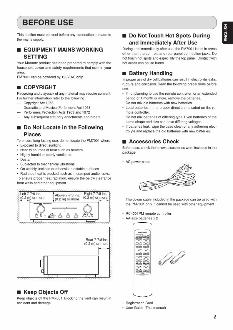
To ensure long-lasting use, do not locate the PM7001 where:• Exposed to direct sunlight.• Near to sources of heat such as heaters.• Highly humid or poorly ventilated.• Dusty.• Subjected to mechanical vibrations.• On wobbly, inclined or otherwise unstable surfaces• Radiated heat is blocked such as in cramped audio racks.To ensure proper heat radiation, ensure the below clearancefrom walls and other equipment.
77777 Keep Objects OffKeep objects off the PM7001. Blocking the vent can result inaccident and damage.
BEFORE USE
77777 Do Not Touch Hot Spots Duringand Immediately After Use
During and immediately after use, the PM7001 is hot in areasother than the controls and rear panel connection jacks. Donot touch hot spots and especially the top panel. Contact withhot areas can cause burns.
77777 Battery HandlingImproper use of dry cell batteries can result in electrolyte leaks,rupture and corrosion. Read the following precautions beforeuse.• If not planning to use the remote controller for an extended
period of 1 month or more, remove the batteries.• Do not mix old batteries with new batteries.• Load batteries in the proper direction indicated on the re-
mote controller.• Do not mix batteries of differing type. Even batteries of the
same shape and size can have differing voltages.• If batteries leak, wipe the case clean of any adhering elec-
trolyte and replace the old batteries with new batteries.
77777 Accessories CheckBefore use, check the below accessories were included in thepackage.
• AC power cable
The power cable included in the package can be used withthe PM7001 only. It cannot be used with other equipment.
• RC4001PM remote controller• AA-size batteries x 2
• Registration Card• User Guide (This manual)
RECORDERRECORDER 2211AUX/DVDAUX/DVDTUNERTUNERPHONOPHONO CDCD
STANDBYSTANDBY
SPEAKERSSPEAKERS
OFFOFFONON
INTEGRATED AMPLIFIER PM7001INTEGRATED AMPLIFIER PM7001
TREBLETREBLE BALANCEBALANCE
POWER ON/OFFPOWER ON/OFF PHONESPHONES
BASSBASS
RECORDER2RECORDER2
INPUT SELECTORINPUT SELECTOR
RRLL
VOLUMEVOLUME
++--++--RECORDER1RECORDER1
RECORDER2RECORDER2RECORDER1RECORDER1
TUNERTUNER
PHONOPHONO
MAXMAXMINMIN
AA SOURCE DIRECTSOURCE DIRECTBB
COPYCOPY
OFFOFFSELECTORSELECTOR REC REC
CDCD
AUX/DVDAUX/DVD
ONONOFFOFF
Left 7-7/8 ins.(0.2 m) or more
Above 7-7/8 ins.(0.2 m) or more
Right 7-7/8 ins.(0.2 m) or more
Rear 7-7/8 ins.(0.2 m) or more
PM7001U 01 Eng(P01-P05) 06.1.19, 4:02 PMPage 1 Adobe PageMaker 6.5J/PPC
2
EN
GL
ISH
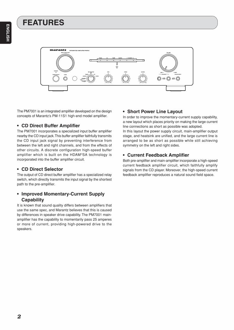
The PM7001 is an integrated amplifier developed on the designconcepts of Marantz’s PM-11S1 high-end model amplifier.
• CD Direct Buffer AmplifierThe PM7001 incorporates a specialized input buffer amplifiernearby the CD input jack. This buffer amplifier faithfully transmitsthe CD input jack signal by preventing interference frombetween the left and right channels, and from the effects ofother circuits. A discrete configuration high-speed bufferamplifier which is built on the HDAM®SA technology isincorporated into the buffer amplifier circuit.
• CD Direct SelectorThe output of CD direct buffer amplifier has a specialized relayswitch, which directly transmits the input signal by the shortestpath to the pre-amplifier.
• Improved Momentary-Current SupplyCapability
It is known that sound quality differs between amplifiers thatuse the same spec, and Marantz believes that this is causedby differences in speaker drive capability. The PM7001 main-amplifier has the capability to momentarily pass 25 amperesor more of current, providing high-powered drive to thespeakers.
FEATURES
MUTEMUTE
RECORDERRECORDER 2211AUX/DVDAUX/DVDTUNERTUNERPHONOPHONO CDCD
STANDBYSTANDBY
SPEAKERSSPEAKERS
OFFOFFONON
INTEGRATED AMPLIFIER PM7001INTEGRATED AMPLIFIER PM7001
TREBLETREBLE BALANCEBALANCE
POWER ON/OFFPOWER ON/OFF PHONESPHONES
BASSBASS
RECORDER2RECORDER2
INPUT SELECTORINPUT SELECTOR
RRLL
VOLUMEVOLUME
++--++--1 21 2
2 12 1RECORDERRECORDER
TUNERTUNER
PHONOPHONO
MAXMAXMINMIN
11 SOURCE DIRECTSOURCE DIRECT22
COPYCOPY
OFFOFF
REC SELECTORREC SELECTOR
CDCD
AUX/DVDAUX/DVD
ONONOFFOFF
• Short Power Line LayoutIn order to improve the momentary-current supply capability,a new layout which places priority on making the large currentline connections as short as possible was adopted.In this layout the power supply circuit, main-amplifier outputstage, and heatsink are unified, and the large current line isarranged to be as short as possible while still achievingsymmetry on the left and right sides.
• Current Feedback AmplifierBoth pre-amplifier and main-amplifier incorporate a high-speedcurrent feedback amplifier circuit, which faithfully amplifysignals from the CD player. Moreover, the high-speed currentfeedback amplifier reproduces a natural sound field space.
PM7001U 01 Eng(P01-P05) 06.1.19, 4:02 PMPage 2 Adobe PageMaker 6.5J/PPC
3
EN
GL
ISHBEFORE MAKING CONNECTIONS
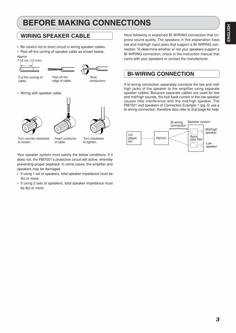
Your speaker system must satisfy the below conditions. If itdoes not, the PM7001’s protective circuit will active, wherebypreventing proper playback. In some cases, the amplifier andspeakers may be damaged.• If using 1 set of speakers, total speaker impedance must be
4Ω or more.• If using 2 sets of speakers, total speaker impedance must
be 8Ω or more.
WIRING SPEAKER CABLE
• Be careful not to short circuit in wiring speaker cables.• Peel off the corting of speaker cable as shown below.
• Wiring with speaker cable.
Approx.7/16 ins. (10 mm)
Cut the corting ofcable.
Peel off theedge of cable.
Twistconductors.
Turn counter-clockwiseto loosen.
Insert conductorof cable.
Turn clockwiseto tighten.
CDplayer,etc.
Bi-wiringconnection
Speaker system
Bandpass filter
Mid/highspeaker
Lowspeaker
PM7001
Here following is explained BI-WIRING connection that im-prove sound quality. The speakers in this explanation havelow and mid/high input jacks that support a BI-WIRING con-nection. To determine whether or not your speakers support aBI-WIRING connection, check in the instruction manual thatcame with your speakers or contact the manufacturer.
BI-WIRING CONNECTION
A bi-wiring connection separately connects the low and mid/high jacks of the speaker to the amplifier using separatespeaker cables. Because separate cables are used for lowand mid/high sounds, the kick back current in the low speakercauses little interference with the mid/high speaker. ThePM7001 and speakers of Connection Example 1 (pg. 5) use abi-wiring connection, therefore also refer to that page for help.
PM7001U 01 Eng(P01-P05) 06.1.19, 4:02 PMPage 3 Adobe PageMaker 6.5J/PPC

4
EN
GL
ISH
MODEL NO. PM7001
LL SYSTEM 1 OR SYSTEM 2 4 -16 OHMSSYSTEM 1 AND SYSTEM 2 8 -16 OHMS
SPEAKERS
RR
LL
MAIN INMAIN IN
LL
RR
PRE OUTPRE OUT
GNDGND
RR
LL
CDCD AUXAUX// DVDDVD
TUNERTUNEROUTOUTININ
RECORDER 1RECORDER 1OUTOUTININ
RECORDER 2RECORDER 2
AC INRR
LL
RR
OFF
SEPARATE
OUT
IN
REMOTECONTROL SERIAL NO.
PHONOPHONO
ON
Record Player
Tuner
DVD Player
CD-R, etc.
MD or Tape deck, etc.
To LINE OUT jacks
To LINE OUT jacks
To LINE OUT jacks
To LINE OUT jacks
To LINE IN jacks
To LINE OUT jacks
To LINE IN jacks
CD player
CONNECTIONSConnection Example : Basic Connection for Stereo PlaybackRefer also to the instruction manuals of components to connect equipment correctly.
PM7001U 01 Eng(P01-P05) 06.1.19, 4:02 PMPage 4 Adobe PageMaker 6.5J/PPC
5
EN
GL
ISH
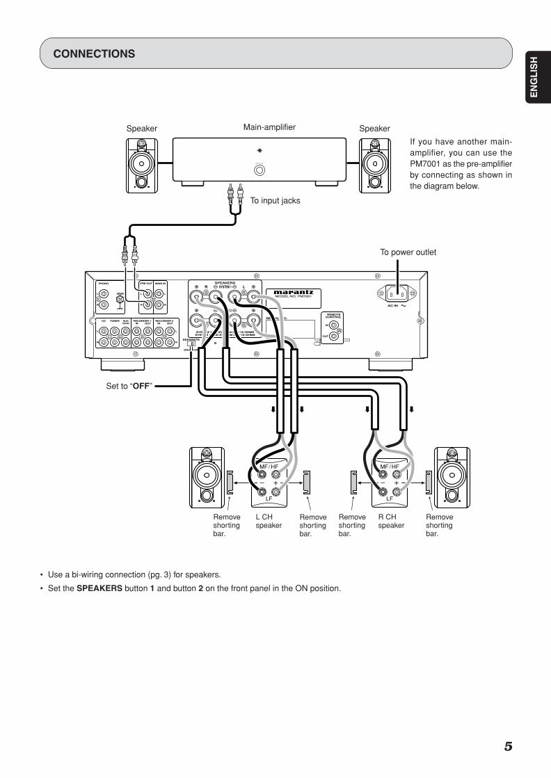
CONNECTIONS
If you have another main-amplifier, you can use thePM7001 as the pre-amplifierby connecting as shown inthe diagram below.
MODEL NO. PM7001
LL SYSTEM 1 OR SYSTEM 2 4SYSTEM 1 OR SYSTEM 2 4 --16 OHMS16 OHMSSYSTEM 1 AND SYSTEM 2 8SYSTEM 1 AND SYSTEM 2 8 --16 OHMS16 OHMS
SPEAKERSSPEAKERS
RR
LL
MAIN INMAIN IN
LL
RR
PRE OUTPRE OUT
GNDGND
RR
LL
CDCD AUXAUX// DVDDVD
TUNERTUNEROUTOUTININ
RECORDER 1RECORDER 1OUTOUTININ
RECORDER 2RECORDER 2
AC INAC INRR
LL
RR
OFFOFF
SEPARATESEPARATE
OUTOUT
ININ
REMOTEREMOTECONTROL CONTROL SERIAL NO.SERIAL NO.
PHONOPHONO
ONON
R LSYSTEM 1
SYSTEM 2
POWER ON/OFF
MF / HF
LF
MF / HF
LF
• Use a bi-wiring connection (pg. 3) for speakers.
• Set the SPEAKERS button 1 and button 2 on the front panel in the ON position.
Speaker Main-amplifier
To input jacks
To power outlet
Removeshortingbar.
R CHspeaker
Removeshortingbar.
Removeshortingbar.
L CHspeaker
Removeshortingbar.
Speaker
Set to “OFF”
PM7001U 01 Eng(P01-P05) 06.1.19, 4:02 PMPage 5 Adobe PageMaker 6.5J/PPC

6
EN
GL
ISH
NAMES AND FUNCTIONS OF PARTS
FRONT PANEL
q POWER ON/OFF buttonPressing this button once turns power to the amplifier ON,and pressing it again turns power to the amplifier OFF.When the button is in the ON position, power can beswitched ON/OFF using the supplied remote controller.If the power is switched OFF using the remote controller,the amplifier engages in standby mode. When in this mode,you cannot switch the power ON by pressing the POWERON/OFF button q. The amplifier remains in standby modeeven if this button is pressed. To switch the power ON,either turn the INPUT SELECTOR knob e or press theMAIN POWER ON button z on the remote controller.
w STANDBY indicatorThis indicator is lit red when the amplifier is in standby mode.When in standby mode, you can switch the power ON by usingthe MAIN POWER ON button z on the remote controller. Ifthe amplifier’s protective circuit activates, this indicator flashesand the amplifier’s power automatically shuts off.
e INPUT SELECTOR knobThis knob selects the input source for playback. Theselected input source is displayed on the function indicator.The amplifier memorize the selected input source whenthe power is turned OFF, and then re-selects the sameinput source when the power is turned ON again.
r MUTE indicatorWhen the MUTE button c on the remote controller is pressed,the MUTE function is activated and the volume is lowered.Pressing the MUTE button c again releases the MUTEfunction. Moreover, the MUTE function can also be releasedby pressing the VOLUME 3/4 button c on the remotecontroller. If the amplifier’s protective circuit activates, thisindicator flashes for approx. 15 seconds and the MUTEfunction activates. While this indicator is flashing, the VOLUMEknob u automatically turns and the volume decreases.
t Function indicatorThis indicator displays the input source currently selectedby the INPUT SELECTOR knob e.
y Power indicatorThis indicator is lit a blue color while power to the PM7001is ON.
MUTEMUTE
RECORDERRECORDER 2211AUX/DVDAUX/DVDTUNERTUNERPHONOPHONO CDCD
STANDBYSTANDBY
SPEAKERSSPEAKERS
OFFOFFONON
INTEGRATED AMPLIFIER PM7001INTEGRATED AMPLIFIER PM7001
TREBLETREBLE BALANCEBALANCE
POWER ON/OFFPOWER ON/OFF PHONESPHONES
BASSBASS
RECORDER2RECORDER2
INPUT SELECTORINPUT SELECTOR
RRLL
VOLUMEVOLUME
++--++--1 21 2
2 12 1RECORDERRECORDER
TUNERTUNER
PHONOPHONO
MAXMAXMINMIN
11 SOURCE DIRECTSOURCE DIRECT22
COPYCOPY
OFFOFF
REC SELECTORREC SELECTOR
CDCD
AUX/DVDAUX/DVD
ONONOFFOFF
qw r ye u
i!0!1!2!3!4 o
t
u VOLUME knobTurning this knob clockwise increases the volume, whileturning it counterclockwise decreases the volume. Thevolume can also be adjusted using the remote controller. Ifthe amplifier’s protective circuit activates, the VOLUMEknob u automatically turns for approx. 15 seconds andthe volume decreases.
i SOURCE DIRECT buttonWhen this button is pressed in, the audio signal istransmitted bypassing the balance and tone control circuits,allowing you to enjoy a higher level of sound quality.
o SPEAKERS 1/2 buttonsThese buttons turn the speaker output to the speakersconnected to the SPEAKERS SYSTEM 1 and 2 terminalsE on the rear panel ON and OFF. When listening withheadphones, turn the speaker output OFF.
!0 BALANCE knobThis knob is used to adjust the sound level from one ofeither the L (left) or R (right) channels. If the BALANCEknob !0 is turned all the way round to one side, sound isnot output from the opposite side.Please note that this knob does not function when theSOURCE DIRECT button i is in the ON position.
!1 Tone Control knobs (BASS/TREBLE)These knobs are used to adjust the BASS and TREBLEsound level. Turning the knobs clockwise increases thesound level, and turning them counterclockwise decreasesthe sound level. Please note that these knobs do notfunction when the SOURCE DIRECT button i is in theON position.
!2 REC SELECTOR knobThis knob switches the input sources for recording.Moreover, you can connect a tape deck, CD-R player, andother such device to the RECORDER 1 and 2 terminals IJ to make copies. We recommend the knob be set to theOFF position when not recording to obtain optimal soundquality. (See page 11.)
PM7001U 01 Eng(P06-P15) 06.1.19, 4:03 PMPage 6 Adobe PageMaker 6.5J/PPC

7
EN
GL
ISH
REAR PANEL
NAMES AND FUNCTIONS OF PARTS
A PHONO Input jacksThese jacks are for connecting to an analog record player.MM cartridges can be used.
B PHONO GND terminalConnect the grounding wire from an analog record player.
C PRE OUT jacksThese jacks are for connecting to the input jacks of an-other main-amplifier or active subwoofer.
D MAIN IN jacksThese jacks are for connecting to the output terminals ofanother pre-amplifier when using the PM7001 as the main-amplifier. In this case, set the SEPARATE switch H to theON position.
E SPEAKERS SYSTEM 1, 2 output terminalsYou can connect 2 speaker systems, SPEAKERS 1 andSPEAKERS 2 E. Speaker output can be turned ON/OFFfrom the SPEAKERS 1 and 2 buttons o on the front panel.
F AC IN socketConnect the supplied AC power cable to this socket and apower outlet.
G REMOTE CONTROL jacksThese jacks are for connecting to other Marantzcomponents such as a CD player or DVD player that has aremote control connector (D.BUS jack).You can use the remote controller supplied with the PM7001to control the system.For more details, see page 13.
MODEL NO. PM7001
LL SYSTEM 1 OR SYSTEM 2 4SYSTEM 1 OR SYSTEM 2 4 --16 OHMS16 OHMSSYSTEM 1 AND SYSTEM 2 8SYSTEM 1 AND SYSTEM 2 8 --16 OHMS16 OHMS
SPEAKERSSPEAKERS
RR
LL
MAIN INMAIN IN
LL
RR
PRE OUTPRE OUT
GNDGND
RR
LL
CDCD AUXAUX// DVDDVD
TUNERTUNEROUTOUTININ
RECORDER 1RECORDER 1OUTOUTININ
RECORDER 2RECORDER 2
AC INAC INRR
LL
RR
OFFOFF
SEPARATESEPARATE
OUTOUT
ININ
REMOTEREMOTECONTROL CONTROL SERIAL NO.SERIAL NO.
PHONOPHONO
ONON
R LSYSTEM 1
SYSTEM 2
A C D E F
GHIJKLM
B
H SEPARATE switchThis switch is used for selecting the pre-amplifier and main-amplifier connection modes.OFF: Select this position when the amplifier is used as a
normal integrated amplifier. (Standard factory set-ting)
ON: The pre-amplifier and main-amplifier are separated.The PM7001 can be used as a main-amplifier wheninput is connected to the MAIN IN jacks D.
I RECORDER 1/RECORDER 2 output jacksThese jacks are for connecting to the recording input jacksof a CD-R recorder, MD deck, tape deck, etc. Output sig-nals can be selected using the REC SELECTOR knob !2
on the front panel.
J RECORDER 1/RECORDER 2 input jacksThese jacks are for connecting to the output jacks of a CD-R player, MD deck, tape deck, etc.
K AUX/DVD input jacksThese jacks are for connecting to the output jacks of aDVD player or other LINE component.
L TUNER input jacksThese jacks are for connecting to the output jacks of atuner or other LINE component.
M CD input jacksThese jacks are for connecting to the output jacks of a CDplayer or similar component.
!3 Infrared Receptor WindowThis is the receptor of control signals sent from theRC4001PM remote controller. Point the remote controllertowards this window to properly transmit signals.
!4 PHONES jackThis jack is for connecting headphones with a standardstereo plug. To listen with headphones, turn the speakeroutput OFF by setting the SPEAKERS 1 and 2 buttons oin the OFF position.
PM7001U 01 Eng(P06-P15) 06.1.19, 4:03 PMPage 7 Adobe PageMaker 6.5J/PPC
8
EN
GL
ISH RC4001PM REMOTE CONTROLLER
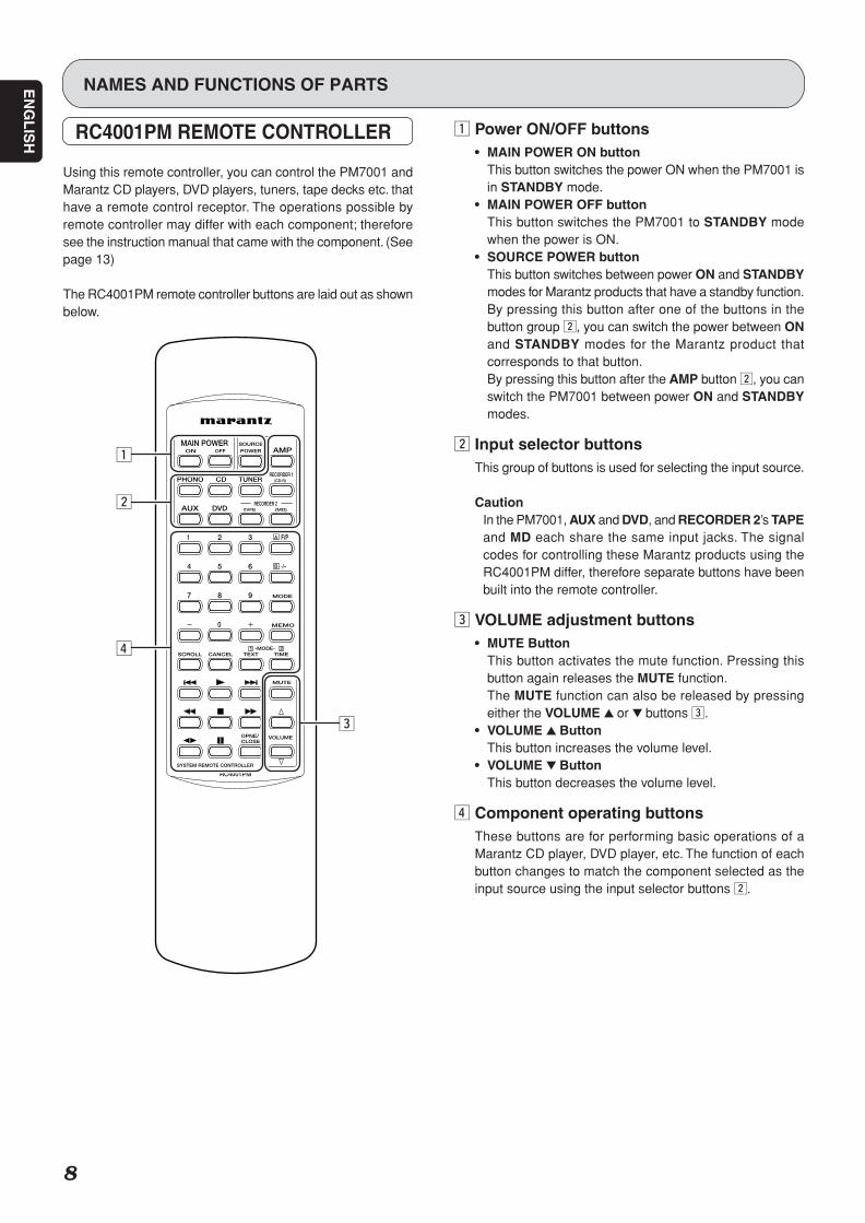
Using this remote controller, you can control the PM7001 andMarantz CD players, DVD players, tuners, tape decks etc. thathave a remote control receptor. The operations possible byremote controller may differ with each component; thereforesee the instruction manual that came with the component. (Seepage 13)
The RC4001PM remote controller buttons are laid out as shownbelow.
z Power ON/OFF buttons• MAIN POWER ON button
This button switches the power ON when the PM7001 isin STANDBY mode.
• MAIN POWER OFF buttonThis button switches the PM7001 to STANDBY modewhen the power is ON.
• SOURCE POWER buttonThis button switches between power ON and STANDBYmodes for Marantz products that have a standby function.By pressing this button after one of the buttons in thebutton group x, you can switch the power between ONand STANDBY modes for the Marantz product thatcorresponds to that button.By pressing this button after the AMP button x, you canswitch the PM7001 between power ON and STANDBYmodes.
x Input selector buttonsThis group of buttons is used for selecting the input source.
CautionIn the PM7001, AUX and DVD, and RECORDER 2’s TAPEand MD each share the same input jacks. The signalcodes for controlling these Marantz products using theRC4001PM differ, therefore separate buttons have beenbuilt into the remote controller.
c VOLUME adjustment buttons• MUTE Button
This button activates the mute function. Pressing thisbutton again releases the MUTE function.The MUTE function can also be released by pressingeither the VOLUME 3 or 4 buttons c.
• VOLUME 3 ButtonThis button increases the volume level.
• VOLUME 4 ButtonThis button decreases the volume level.
v Component operating buttonsThese buttons are for performing basic operations of aMarantz CD player, DVD player, etc. The function of eachbutton changes to match the component selected as theinput source using the input selector buttons x.
NAMES AND FUNCTIONS OF PARTS
z
x
v
c
PM7001U 01 Eng(P06-P15) 06.1.19, 4:03 PMPage 8 Adobe PageMaker 6.5J/PPC
9
EN
GL
ISH
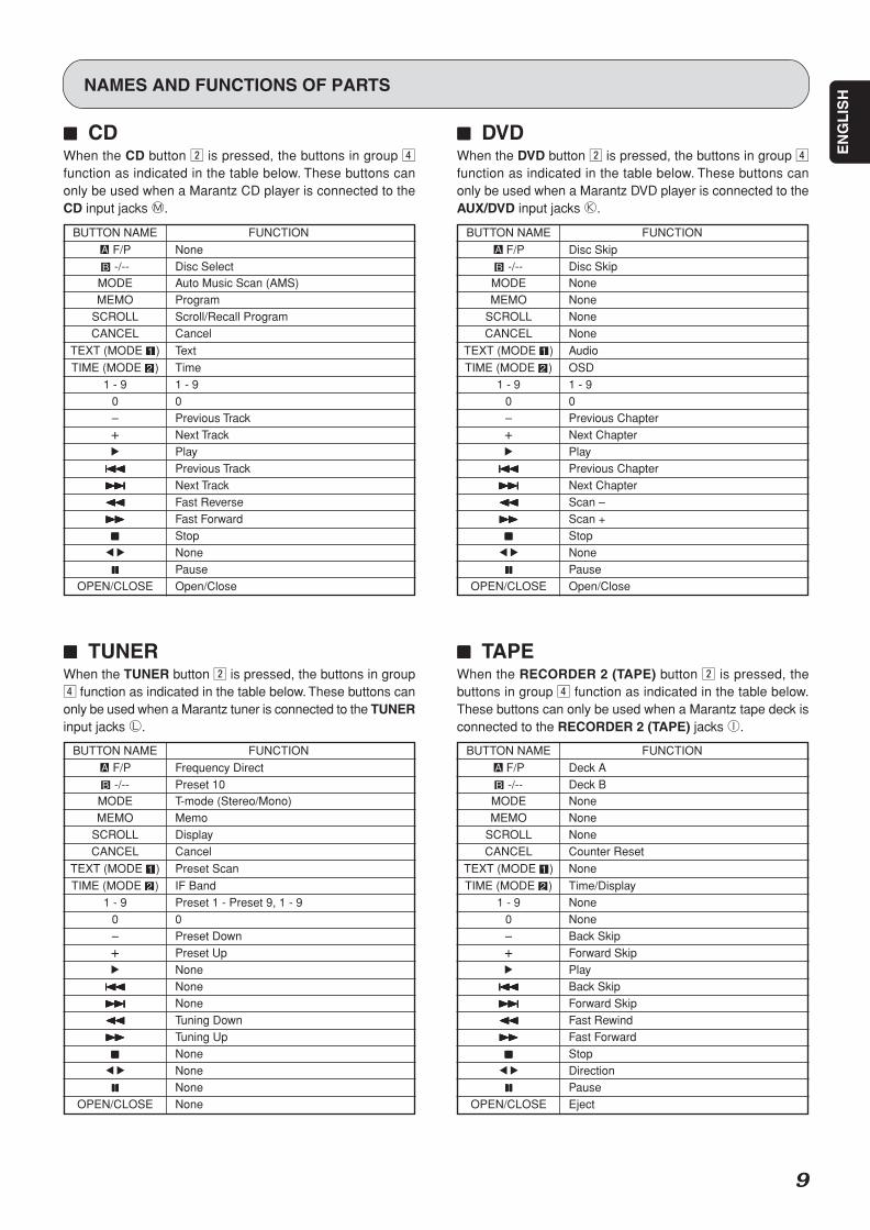
77777 CDWhen the CD button x is pressed, the buttons in group vfunction as indicated in the table below. These buttons canonly be used when a Marantz CD player is connected to theCD input jacks M.
BUTTON NAME FUNCTION
F/P None -/-- Disc Select
MODE Auto Music Scan (AMS)MEMO Program
SCROLL Scroll/Recall ProgramCANCEL Cancel
TEXT (MODE ) Text
TIME (MODE ) Time1 - 9 1 - 9
0 0– Previous Track+ Next Track2 Play
44444 Previous Track
¢¢¢¢¢ Next Track
11111 Fast Reverse
¡¡¡¡¡ Fast Forward
77777 Stop1 2 None
88888 PauseOPEN/CLOSE Open/Close
77777 TUNERWhen the TUNER button x is pressed, the buttons in groupv function as indicated in the table below. These buttons canonly be used when a Marantz tuner is connected to the TUNERinput jacks L.
NAMES AND FUNCTIONS OF PARTS
77777 DVDWhen the DVD button x is pressed, the buttons in group vfunction as indicated in the table below. These buttons canonly be used when a Marantz DVD player is connected to theAUX/DVD input jacks K.
77777 TAPEWhen the RECORDER 2 (TAPE) button x is pressed, thebuttons in group v function as indicated in the table below.These buttons can only be used when a Marantz tape deck isconnected to the RECORDER 2 (TAPE) jacks I.
BUTTON NAME FUNCTION
F/P Disc Skip -/-- Disc Skip
MODE NoneMEMO None
SCROLL NoneCANCEL None
TEXT (MODE ) Audio
TIME (MODE ) OSD1 - 9 1 - 9
0 0– Previous Chapter+ Next Chapter2 Play
44444 Previous Chapter
¢¢¢¢¢ Next Chapter
11111 Scan –
¡¡¡¡¡ Scan +
77777 Stop1 2 None
88888 PauseOPEN/CLOSE Open/Close
BUTTON NAME FUNCTION
F/P Frequency Direct -/-- Preset 10
MODE T-mode (Stereo/Mono)MEMO Memo
SCROLL DisplayCANCEL Cancel
TEXT (MODE ) Preset Scan
TIME (MODE ) IF Band1 - 9 Preset 1 - Preset 9, 1 - 9
0 0– Preset Down+ Preset Up2 None
44444 None
¢¢¢¢¢ None
11111 Tuning Down
¡¡¡¡¡ Tuning Up
77777 None1 2 None
88888 NoneOPEN/CLOSE None
BUTTON NAME FUNCTION
F/P Deck A -/-- Deck B
MODE NoneMEMO None
SCROLL NoneCANCEL Counter Reset
TEXT (MODE ) None
TIME (MODE ) Time/Display1 - 9 None
0 None– Back Skip+ Forward Skip2 Play
44444 Back Skip
¢¢¢¢¢ Forward Skip
11111 Fast Rewind
¡¡¡¡¡ Fast Forward
77777 Stop1 2 Direction
88888 PauseOPEN/CLOSE Eject
PM7001U 01 Eng(P06-P15) 06.1.19, 4:03 PMPage 9 Adobe PageMaker 6.5J/PPC
10
EN
GL
ISH
NAMES AND FUNCTIONS OF PARTS
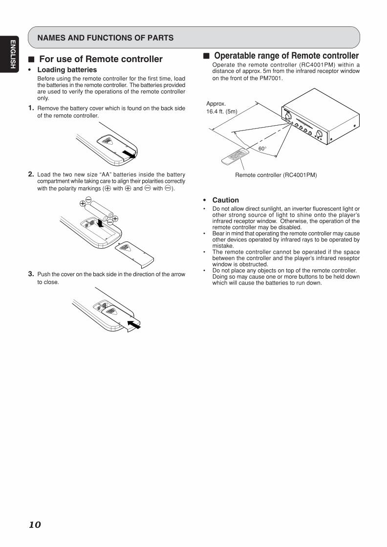
77777 For use of Remote controller• Loading batteries
Before using the remote controller for the first time, loadthe batteries in the remote controller. The batteries providedare used to verify the operations of the remote controlleronly.
1. Remove the battery cover which is found on the back sideof the remote controller.
2. Load the two new size “AA” batteries inside the batterycompartment while taking care to align their polarities correctlywith the polarity markings ( with and with ).
3. Push the cover on the back side in the direction of the arrowto close.
77777 Operatable range of Remote controllerOperate the remote controller (RC4001PM) within adistance of approx. 5m from the infrared receptor windowon the front of the PM7001.
• Caution• Do not allow direct sunlight, an inverter fluorescent light or
other strong source of light to shine onto the player’sinfrared receptor window. Otherwise, the operation of theremote controller may be disabled.
• Bear in mind that operating the remote controller may causeother devices operated by infrared rays to be operated bymistake.
• The remote controller cannot be operated if the spacebetween the controller and the player’s infrared reseptorwindow is obstructed.
• Do not place any objects on top of the remote controller.Doing so may cause one or more buttons to be held downwhich will cause the batteries to run down.
Remote controller (RC4001PM)
60°
Approx.16.4 ft. (5m)
PM7001U 01 Eng(P06-P15) 06.1.19, 4:03 PMPage 10 Adobe PageMaker 6.5J/PPC
11
EN
GL
ISH
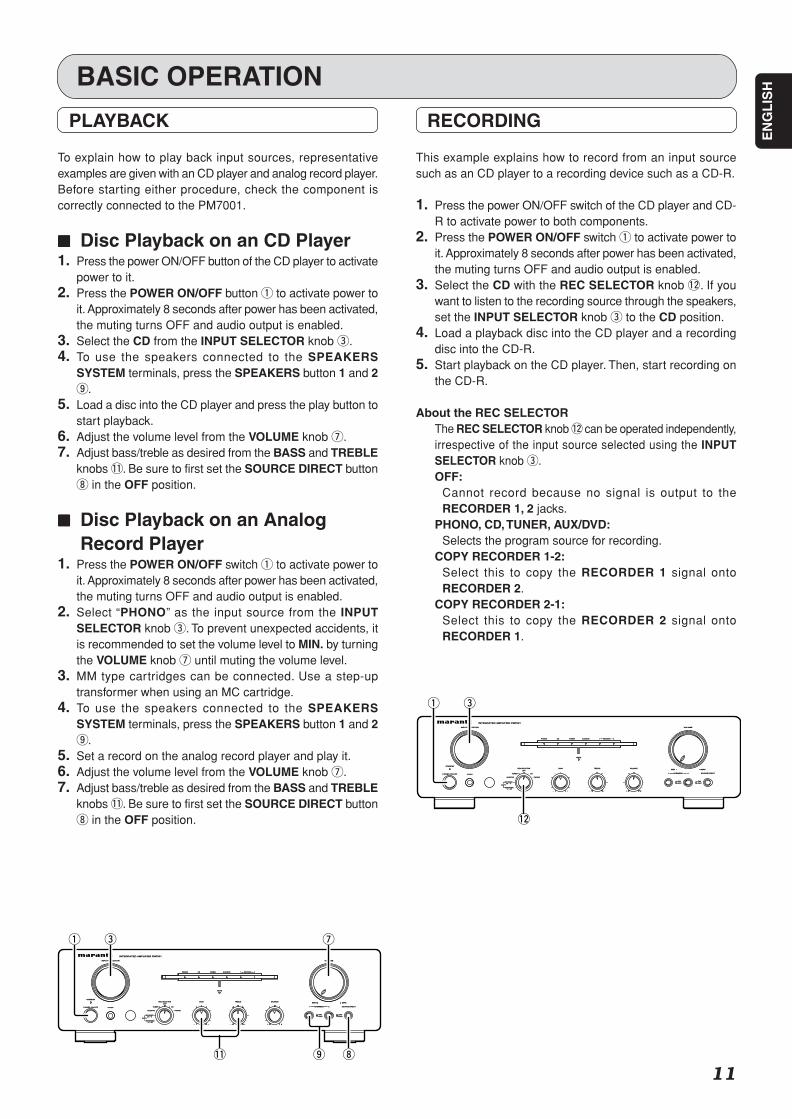
PLAYBACK
To explain how to play back input sources, representativeexamples are given with an CD player and analog record player.Before starting either procedure, check the component iscorrectly connected to the PM7001.
77777 Disc Playback on an CD Player1. Press the power ON/OFF button of the CD player to activate
power to it.2. Press the POWER ON/OFF button q to activate power to
it. Approximately 8 seconds after power has been activated,the muting turns OFF and audio output is enabled.
3. Select the CD from the INPUT SELECTOR knob e.4. To use the speakers connected to the SPEAKERS
SYSTEM terminals, press the SPEAKERS button 1 and 2o.
5. Load a disc into the CD player and press the play button tostart playback.
6. Adjust the volume level from the VOLUME knob u.7. Adjust bass/treble as desired from the BASS and TREBLE
knobs !1. Be sure to first set the SOURCE DIRECT buttoni in the OFF position.
77777 Disc Playback on an AnalogRecord Player
1. Press the POWER ON/OFF switch q to activate power toit. Approximately 8 seconds after power has been activated,the muting turns OFF and audio output is enabled.
2. Select “PHONO” as the input source from the INPUTSELECTOR knob e. To prevent unexpected accidents, itis recommended to set the volume level to MIN. by turningthe VOLUME knob u until muting the volume level.
3. MM type cartridges can be connected. Use a step-uptransformer when using an MC cartridge.
4. To use the speakers connected to the SPEAKERSSYSTEM terminals, press the SPEAKERS button 1 and 2o.
5. Set a record on the analog record player and play it.6. Adjust the volume level from the VOLUME knob u.7. Adjust bass/treble as desired from the BASS and TREBLE
knobs !1. Be sure to first set the SOURCE DIRECT buttoni in the OFF position.
BASIC OPERATION
RECORDING
This example explains how to record from an input sourcesuch as an CD player to a recording device such as a CD-R.
1. Press the power ON/OFF switch of the CD player and CD-R to activate power to both components.
2. Press the POWER ON/OFF switch q to activate power toit. Approximately 8 seconds after power has been activated,the muting turns OFF and audio output is enabled.
3. Select the CD with the REC SELECTOR knob !2. If youwant to listen to the recording source through the speakers,set the INPUT SELECTOR knob e to the CD position.
4. Load a playback disc into the CD player and a recordingdisc into the CD-R.
5. Start playback on the CD player. Then, start recording onthe CD-R.
About the REC SELECTORThe REC SELECTOR knob !2 can be operated independently,irrespective of the input source selected using the INPUTSELECTOR knob e.OFF:
Cannot record because no signal is output to theRECORDER 1, 2 jacks.
PHONO, CD, TUNER, AUX/DVD:Selects the program source for recording.
COPY RECORDER 1-2:Select this to copy the RECORDER 1 signal ontoRECORDER 2.
COPY RECORDER 2-1:Select this to copy the RECORDER 2 signal ontoRECORDER 1.
MUTEMUTE
RECORDERRECORDER 2211AUX/DVDAUX/DVDTUNERTUNERPHONOPHONO CDCD
STANDBYSTANDBY
SPEAKERSSPEAKERS
OFFOFFONON
INTEGRATED AMPLIFIER PM7001INTEGRATED AMPLIFIER PM7001
TREBLETREBLE BALANCEBALANCE
POWER ON/OFFPOWER ON/OFF PHONESPHONES
BASSBASS
RECORDER2RECORDER2
INPUT SELECTORINPUT SELECTOR
RRLL
VOLUMEVOLUME
++--++--1 21 2
2 12 1RECORDERRECORDER
TUNERTUNER
PHONOPHONO
MAXMAXMINMIN
11 SOURCE DIRECTSOURCE DIRECT22
COPYCOPY
OFFOFF
REC SELECTORREC SELECTOR
CDCD
AUX/DVDAUX/DVD
ONONOFFOFF
q e u
i!1 o
MUTEMUTE
RECORDERRECORDER 2211AUX/DVDAUX/DVDTUNERTUNERPHONOPHONO CDCD
STANDBYSTANDBY
SPEAKERSSPEAKERS
OFFOFFONON
INTEGRATED AMPLIFIER PM7001INTEGRATED AMPLIFIER PM7001
TREBLETREBLE BALANCEBALANCE
POWER ON/OFFPOWER ON/OFF PHONESPHONES
BASSBASS
RECORDER2RECORDER2
INPUT SELECTORINPUT SELECTOR
RRLL
VOLUMEVOLUME
++--++--1 21 2
2 12 1RECORDERRECORDER
TUNERTUNER
PHONOPHONO
MAXMAXMINMIN
11 SOURCE DIRECTSOURCE DIRECT22
COPYCOPY
OFFOFF
REC SELECTORREC SELECTOR
CDCD
AUX/DVDAUX/DVD
ONONOFFOFF
q e
!2
PM7001U 01 Eng(P06-P15) 06.1.19, 4:03 PMPage 11 Adobe PageMaker 6.5J/PPC
12
EN
GL
ISH
MODEL NO. PM7001
LL SYSTEM 1 OR SYSTEM 2 4SYSTEM 1 OR SYSTEM 2 4 --16 OHMS16 OHMSSYSTEM 1 AND SYSTEM 2 8SYSTEM 1 AND SYSTEM 2 8 --16 OHMS16 OHMS
SPEAKERSSPEAKERS
RR
LL
MAIN INMAIN IN
LL
RR
PRE OUTPRE OUT
GNDGND
RR
LL
CDCD AUXAUX// DVDDVD
TUNERTUNEROUTOUTININ
RECORDER 1RECORDER 1OUTOUTININ
RECORDER 2RECORDER 2
AC INAC INRR
LL
RR
OFFOFF
SEPARATESEPARATE
OUTOUT
ININ
REMOTEREMOTECONTROL CONTROL SERIAL NO.SERIAL NO.
PHONOPHONO
ONON
R LSYSTEM 1
SYSTEM 2
MF / HF
LF
MF / HF
LF
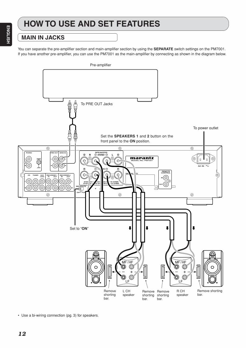
HOW TO USE AND SET FEATURES
MAIN IN JACKS
You can separate the pre-amplifier section and main-amplifier section by using the SEPARATE switch settings on the PM7001.If you have another pre-amplifier, you can use the PM7001 as the main-amplifier by connecting as shown in the diagram below.
Set the SPEAKERS 1 and 2 button on thefront panel to the ON position.
• Use a bi-wiring connection (pg. 3) for speakers.
Remove shortingbar.
R CHspeaker
Removeshortingbar.
Removeshortingbar.
L CHspeaker
Removeshortingbar.
To power outlet
To PRE OUT Jacks
Set to “ON”
Pre-amplifier
PM7001U 01 Eng(P06-P15) 06.2.17, 11:03 AMPage 12 Adobe PageMaker 6.5J/PPC
13
EN
GL
ISH
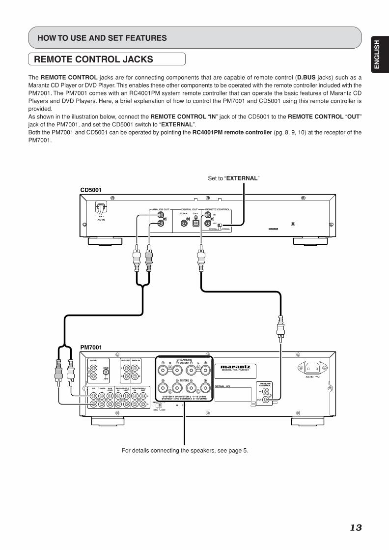
REMOTE CONTROL JACKS
The REMOTE CONTROL jacks are for connecting components that are capable of remote control (D.BUS jacks) such as aMarantz CD Player or DVD Player. This enables these other components to be operated with the remote controller included with thePM7001. The PM7001 comes with an RC4001PM system remote controller that can operate the basic features of Marantz CDPlayers and DVD Players. Here, a brief explanation of how to control the PM7001 and CD5001 using this remote controller isprovided.As shown in the illustration below, connect the REMOTE CONTROL “IN” jack of the CD5001 to the REMOTE CONTROL “OUT”jack of the PM7001, and set the CD5001 switch to “EXTERNAL”.Both the PM7001 and CD5001 can be operated by pointing the RC4001PM remote controller (pg. 8, 9, 10) at the receptor of thePM7001.
HOW TO USE AND SET FEATURES
MODEL NO. PM7001
LL SYSTEM 1 OR SYSTEM 2 4SYSTEM 1 OR SYSTEM 2 4 --16 OHMS16 OHMSSYSTEM 1 AND SYSTEM 2 8SYSTEM 1 AND SYSTEM 2 8 --16 OHMS16 OHMS
SPEAKERSSPEAKERS
RR
LL
MAIN INMAIN IN
LL
RR
PRE OUTPRE OUT
GNDGND
RR
LL
CDCD AUXAUX// DVDDVD
TUNERTUNEROUTOUTININ
RECORDER 1RECORDER 1OUTOUTININ
RECORDER 2RECORDER 2
AC INAC INRR
LL
RR
OFFOFF
SEPARATESEPARATE
OUTOUT
ININ
REMOTEREMOTECONTROL CONTROL SERIAL NO.SERIAL NO.
PHONOPHONO
ONON
R LSYSTEM 1
SYSTEM 2
CD5001
PM7001
Set to “EXTERNAL”
For details connecting the speakers, see page 5.
PM7001U 01 Eng(P06-P15) 06.1.19, 4:03 PMPage 13 Adobe PageMaker 6.5J/PPC

14
EN
GL
ISH
TROUBLESHOOTING
77777 Before considering it as a failureIn case of trouble with this component, first check the followingbefore calling for service.What seems to be a serious malfunction is often due to a simpleoperation mistake.If the trouble is not fixed after making the following checks,contact the place of purchase, your nearest Marantz dealer,our customer service center, or our repair service center.
* Power does not turn ON.1. Is the power cable plugged securely into the power outlet?2. Isn’t the STANDBY indicator above the POWER ON/OFF
button lit? Either turn the INPUT SELECTOR knob, or pressthe MAIN POWER ON button on the remote controller.
3. If the STANDBY indicator is flashing, the protective circuithas been activated. Switch the PM7001’s POWER ON/OFFbutton to the OFF position, wait for more than a minute,and then turn the power back ON.
* Nothing is heard from the speakers.1. Aren’t the SPEAKER 1 and 2 buttons on the front panel in
the OFF position?2. Isn’t the MUTE function activated?3. Did you make a mistake selecting the input source using
the INPUT SELECTOR knob on the front panel?4. Are you using the component correctly?5. Are connection cables and speaker cables securely
connected.6. Is the SEPARATE switch on the rear panel set correctly?7. The volume may have been muted by the protective circuit
activated. Try adjusting the volume level again.
* Record player audio is not heard, orcontains a lot of noise.
1. Are the PHONO plugs connected correctly?2. Connect the grounding wire from the record player to the
PHONO GND terminal.3. Is the cartridge connected properly to the tone arm?4. Sometimes plugging the record player’s power cable into
the power outlet with the polarity reversed can reduce noise.
77777 About the Protective CircuitThe PM7001 is equipped with a protective circuit to protectthe amplifier circuits and speaker system against damage.If the protective circuit is activated, the sound is instantly muted.In this case, either the MUTE indicator in the center of thepanel flashes, or the STANDBY indicator above the POWERON/OFF button flashes.
• At Power OnFor about 8 seconds after the power is turned on, the protectivecircuit is activated muting the sound to give the amplifier circuitstime to stabilize. Once the amplifier circuits stabilize, theprotective circuit releases and audio is enabled.
• In the Event of OvercurrentThe protective circuit is activated if current exceeding a certainlevel is detected, which can happen if excessive signal flow isinput to the amplifier or if the PM7001 is connected to a speakersystem of less than 4Ω impedance. The protective circuit isalso activated if a speaker cable shorts.In these cases, the MUTE indicator in the center of the panelflashes, and the volume is automatically reduced. Approximately15 seconds later the protective circuit is released, thereforethe volume needs readjusting to continue normal use.Moreover, if the overcurrent continues, the amplifier’s powershuts OFF and the STANDBY indicator above the POWERON/OFF button flashes.
• If excessive ultra-bass signals are inputThe protective circuit is also activated if ultra-bass signals thatexceed the base signal range settings are input.. In this case,the MUTE indicator in the center of the panel flashes, and thevolume is automatically reduced. Approximately 15 secondslater, the protective circuit is released, therefore the volumeneeds readjusting to continue normal use. If excessive ultra-bass signal input continues or if DC voltage is detected due totrouble with the amplifier, the power shuts OFF and theSTANDBY indicator above the POWER ON/OFF button flashes.
• If the Main-amplifier OverheatsThe protective circuit is activated if the temperature of the main-amplifier section rises above a certain level, which can happenif the amplifier is continually used with excessive signal flowbeing input into it. The protective circuit is also activated whenthe set operating temperature is exceeded, which can happenif the vents on top of the amplifier are covered, or if the amplifieris installed on a cramped audio rack. In these cases, the MUTEindicator in the center of the panel flashes, and the volume isautomatically reduced. Approximately 15 seconds later, theprotective circuit is released, therefore the volume needsreadjusting to continue normal use.If the temperature does not sufficiently lower within a certainamount of time after the protective circuit activation, the powershuts OFF and the STANDBY indicator above the POWERON/OFF button flashes.
• In the Event of Amplifier TroubleThe protective circuit is activated and the power is automaticallyshut OFF if an abnormality is detected in the power circuit.The same happens if the main fuse inside the amplifier blows.In these cases, the STANDBY indicator above the POWERON/OFF button flashes.
PM7001U 01 Eng(P06-P15) 06.1.19, 4:03 PMPage 14 Adobe PageMaker 6.5J/PPC

15
EN
GL
ISHOTHERS
The section describes the care and maintenance tasks thatmust be performed to optimize the operation of your Marantzcomponent.
77777 Cleaning of equipment external surfacesThe exterior finish of your unit will last indefinitely with propercare and cleaning, Never use scouring pads, steel wool,scourging powders or harsh chemical agents (e.g., lye solution),alcohol, thinner, benzine, insecticide or other volatile substancesas these wil mar the finish of the equipment. Likewise, neveruse cloths containing chemical substances. If the equipmentget dirty, wipe the external surfaces with a soft, lint-free cloth.If the equipment becomes heavily soiled:
• dilute some washing up liquidin water, in a ratio of one partdetergent to six parts water.
• dip a soft, lint free in the solutionand wring the it is damp.
• wipe the equipment with thedamp cloth.
• dry the equipment by wiping it with a dry cloth.
77777 RepairsOnly the most competent and qualified service techniciansshould be allowed to service the factory-trained warranty stationpersonnel have the knowledge and special facilities neededfor repair and calibration of this precision equipment. After thewarranty period has expired, repairs will be performed for acharge if the equipment can be returned to normal operation.In the event of difficulty, refer to your dealer or write directly tothe nearest location to you that is listed on the MarantzAuthorized Service Station list. If writing, please include themodel and serial number of the equipment together with a fulldescription of what you think is abnormal about the equipment'sbehaviour.
Power output (20 Hz – 20 kHz simultaneous drive of both channels)...................................................... 70W x 2 (8Ω load).................................................... 100W x 2 (4Ω load)
Total harmonic distortion (20Hz – 20kHz simultaneous driveof both channels, 8Ω load) .......................................... 0.02%Output band width (8Ω load, 0.05%) ................. 5Hz – 60kHzFrequency response (CD, 1W, 8Ω load) .... 5Hz – 100kHz ±3dBDumping factor (8Ω load, 20Hz – 20kHz) ....................... 100Input sensitivity/Input impedance
PHONO (MM) .............................................. 2.5mV/47kΩCD, LINE, TUNER, AUX/DVD, RECORDER
.............................................................. 200mV/20kΩMAIN IN ......................................................... 1.6V/20kΩ
Output voltage/Output impedancePRE OUT ...................................................... 1.6 V/560Ω
Maximum allowable PHONO input level (1kHz)MM ....................................................................... 130mVRIAA deviation (20Hz ~ 20kHz) ............................ ±0.5dB
S/N (IHF-A, 1W, 8Ω load)PHONO (MM) ...................................... 85dB (5mV input)CD, LINE, TUNER, AUX/DVD, RECORDER
................................................... 88dB (500mV input)MAIN IN ................................................................ 107dB
Tone controlBass (50Hz) ........................................................... ±10dBTreble (20kHz) ....................................................... ±10dB
Power requirement ......................................... AC 120V 60HzPower consumption
(UL6500) ................................................................ 250W(4Ω, 100W x 2 output) ............................................ 470W
AccessoriesRemote controller .......................................................... 1AA batteries ................................................................... 2Detachable AC power cable .......................................... 1
Maximum outer dimensions (Amplifier)Width .............................................17-5/16 ins. (440 mm)Height ................................................... 5 ins. (126.5 mm)Depth ...............................................14-3/8 ins. (364 mm)
Weight (Amplifier) ....................................... 23.1 lbs (10.5 kg)
Specifications subject to change without prior notice.
SPECIFICATIONS & DIMENSIONAL DRAWINGS
RECORDERRECORDER 2211AUX/DVDAUX/DVDTUNERTUNERPHONOPHONO CDCD
STANDBYSTANDBY
SPEAKERSSPEAKERS
OFFOFFONON
INTEGRATED AMPLIFIER PM7001INTEGRATED AMPLIFIER PM7001
TREBLETREBLE BALANCEBALANCE
POWER ON/OFFPOWER ON/OFF PHONESPHONES
BASSBASS
RECORDER2RECORDER2
INPUT SELECTORINPUT SELECTOR
RRLL
VOLUMEVOLUME
++--++--RECORDER1RECORDER1
RECORDER2RECORDER2RECORDER1RECORDER1
TUNERTUNER
PHONOPHONO
MAXMAXMINMIN
AA SOURCE DIRECTSOURCE DIRECTBB
COPYCOPY
OFFOFFSELECTORSELECTOR REC REC
CDCD
AUX/DVDAUX/DVD
ONONOFFOFF
14-3
/8 in
s.
(364
mm
)
3/4
ins.
(19.
0 m
m)
5 in
s.
(126
.5 m
m)
17-5/16 ins. (440.0 mm)
15/1
6 in
s.(2
3.0
mm
)
11/1
6 in
s.
(16.
5 m
m)
PM7001U 01 Eng(P06-P15) 06.1.19, 4:03 PMPage 15 Adobe PageMaker 6.5J/PPC

Printed in China
is a registered trademark.
www.marantz.comYou can find your nearest authorized distributor or dealer on our website.
U.S.A. Marantz America, Inc. 1100 Maplewood Drive, Itasca, IL 60143, U.S.A.
EUROPE Marantz Europe B.V. P.O. Box 8744, 5605 LS Eindhoven, The Netherlands
01/2006 00M14AJ851250 mzh-g
PM7001U(Cover) 06.1.19, 4:28 PMPage 4 Adobe PageMaker 6.5J/PPC