march 1999 volume 2, number 1 1999 volume 2, number 1 you can download previous issues of ipj in pdf...
TRANSCRIPT

March 1999 Volume 2, Number 1
You can downloadprevious issues of IPJ in
PDF format from:
www.cisco.com/ipj
A Quarterly Technical Publication for Internet and Intranet Professionals
In This Issue
From the Editor .......................1
Peering and Settlements ...........2
IPv6........................................17
Secure E-Mail ........................30
Book Review..........................44
Letter to the Editor ................46
Fragments ..............................47
F r o m T h e E d i t o r
Today’s Internet is comprised of numerous interconnected
Internet Ser-vice Providers
(ISPs), each serving many constituent networks and endusers. Just as individual regional and national telephone companies in-terconnect and exchange traffic and form a global telephone network,the ISPs must arrange for points of interconnection to provide global In-ternet service. This interconnection mechanism is generally called“peering,” and it is the subject of a two-part article by Geoff Huston. InPart I, which is included in this issue, he discusses the technical aspectsof peering. In Part II, which will follow in our next issue, Mr. Hustoncontinues the examination with a look at the business arrangements(called “settlements”) that exist between ISPs, and discusses the future ofthis rapidly evolving marketplace.
In the early 1990s, concern grew regarding the possible depletion of theIP version 4 address space because of the rapid growth of the Internet.Predictions for when we would literally run out of IP addresses werepublished. Several proposals for a new version of IP were put forward inthe IETF, eventually resulting in IP version 6 or IPv6. At the same time,new technologies were developed that effectively slowed address deple-tion, most notably
Classless Inter-Domain Routing
(CIDR) and
Network Address Translators
(NATs). Today there is still debate as to ifand when IPv6 will be deployed in the global Internet, but experimenta-tion and development continues on this protocol. We asked Robert Finkto give us a status report on IPv6.
We’ve already discussed the historical lack of security in Internet tech-nologies and how security enhancements are being developed for everylayer of the protocol stack. This time, Marshall Rose and David Stromexamine the state of electronic mail security. We clearly have a way togo before we see “seamless integration” of security systems with today’se-mail clients.
Our first Letter to the Editor is included on page 46. As always, wewould love to hear your comments and questions regarding anythingyou read in this journal. Please contact us at
—Ole J. Jacobsen, Editor and Publisher

T h e I n t e r n e t P r o t o c o l J o u r n a l
2
Interconnection, Peering and Settlements—Part I
by Geoff Huston, Telstra
echnology and business models share a common evolutionwithin the Internet. To enable deployment of the technologywithin a service environment, a robust and stable business
model also needs to be created. This tied destiny of technology and busi-ness factors is perhaps most apparent within the area of theinterconnection of
Internet Service Providers
(ISPs). Here there is an in-teraction at a level of technology, in terms of routing signaling andtraffic flows, and also an interaction of business models, in terms of anegotiation of benefit and cost in undertaking the interconnection. Thisarticle examines this environment in some detail, looking closely at theinteraction between the capabilities of the technical protocols, theirtranslation into engineering deployment, and the consequent businessimperatives that such environments create.
It is necessary to commence this examination of the public Internet withthe observation that the Internet is not, and never has been, a single net-work. The Internet is a collection of interconnected componentnetworks that share a common addressing structure, a common view ofrouting and traffic flow, and a common view of a naming system. Thisinterconnection environment spans a highly diverse set of more than50,000 component networks, and this number continues, inexorably, togrow and grow. One of the significant aspects of this environment is thecompetitive Internet service industry, where many thousands of enter-prises, both small and large, compete for market share at a regional,national, and international level.
Underneath the veneer of a highly competitive Internet service market isa somewhat different environment, in which every ISP network must in-teroperate with neighboring Internet networks in order to produce adelivered service outcome of comprehensive connectivity and end-to-endservice. No ISP can operate in complete isolation from others while stilloffering public Internet services, and therefore, every ISP not only mustcoexist with other ISPs but also must operate in cooperation with otherISPs.
This article examines both the technical and business aspects that sur-round this ISP interaction, commonly referred to as “interconnection,peering, and settlements.” It examines the business motivation for inter-connection structures, and then the technical architectures of suchenvironments. The second part looks at the business relationships thatarise between ISPs in the public Internet space, and then examines nu-merous broader issues that will shape the near-term future of thisenvironment.
____________________
[This article is based in part on material in
The ISP Survival Guide,
by Geoff Huston,ISBN 201-3-45567-9, published by Wiley. Used with permission.]
T
T h e I n t e r n e t P r o t o c o l J o u r n a l
3
Interconnection: Retailing, Reselling, and Wholesaling
To provide some motivation for this issue of ISP interconnection, it isfirst appropriate to look at the nature of the environment. The regula-tory framework that defined the traditional structure of othercommunications enterprises such as telephony or postal services waslargely absent in the evolution of the Internet service industry. The result-ant service industry for the Internet is most accurately characterized asan outcome of business and technology interaction, rather than aplanned outcome of some regulatory process. This section examines thisinteraction between business and technology within the ISPenvironment.
A natural outcome of the Internet model is that the effective control ofthe retail service environment rests with a network client of an accessservice rather than with the access service provider. As such, a client ofan ISP access service has the discretionary ability to resell the access ser-vice to third-party clients. In this environment, reselling and wholesalingare very natural developments within the ISP activity sector, with orwithout the explicit concurrence of the provider ISP. The provider ISPmay see this reselling as an additional channel to market for its own In-ternet carriage services, and may adopt a positive stance by activelyencouraging resellers into the market as a means of overall market stim-ulus, while tapping into the marketing, sales, and support resources ofthese reselling entities to continue to drive the volumes of the underlyingInternet carriage service portfolio. The low barriers to entry to thewholesale market provide a means of increasing the scope of the opera-tion, because to lift business cash-flow levels, the business enters intowholesale agreements that effectively resell the carriage components ofthe operation without the bundling of other services normally associ-ated with the retail operation. This process allows the ISP to gain highervolumes of carriage capacity that in turn allow the ISP to gain access tolower unit costs of carriage.
Given that a retail operation can readily become a wholesale provider tothird-party resellers at the effective discretion of the original retail client,is a wholesale transit ISP restricted from undertaking retail operations?Again, there is no such natural restriction from a technical or businessperspective. An Internet carriage service is a commodity service that doesnot allow for a significant level of intrinsic product discrimination. Therelatively low level of value added by a wholesale service operation im-plies a low unit rate of financial return for that operation. This low unitrate of financial return, together with an inability to competitively dis-criminate the wholesale product effectively, induces a wholesaleprovider into the retail sector as a means of improving the financial per-formance of the service operation. The overall result is that many ISPsoperate both as clients and as providers. Few, if any, reasonable techni-cal-based characterizations draw a clear and unambiguous distinctionbetween a client and service provider when access services to networksare considered. A campus network may be a client of one or more ser-

Peering and Settlements—Part I:
continued
T h e I n t e r n e t P r o t o c o l J o u r n a l
4
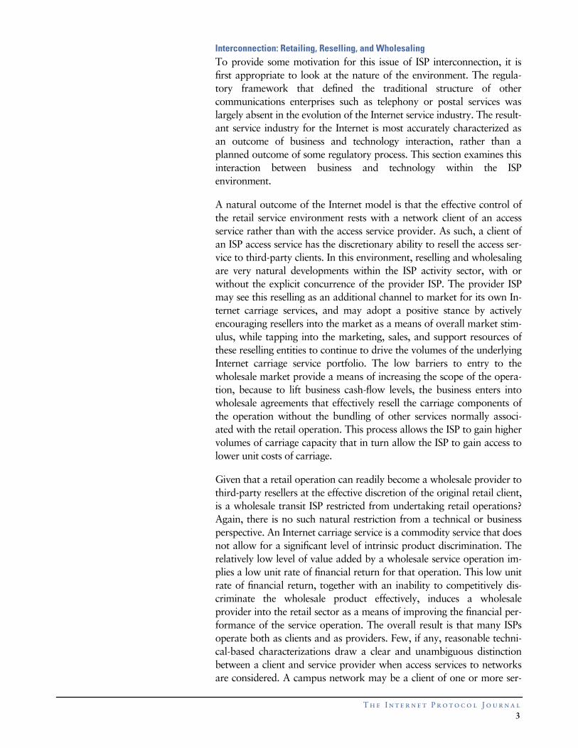
vice providers, while the network is also a service provider to campususers. Indeed most networks in a similar situation take on the dual roleof client and provider, and the ability to resell an access service can ex-tend to almost arbitrary depths of the reselling hierarchy. From thistechnical perspective, very few natural divisions of the market support astable segmentation into exclusively wholesale and exclusively retailmarket sectors. The overall structure of roles is indicated in Figure 1.
Figure 1:ISP Roles andRelationships
The resultant business environment is one characterized by a reason-able degree of fluidity, in which no clear delineation of relative roles ormarkets exists. The ISP market environment is, therefore, one of com-petitive market forces in which each ISP tends to create a retail marketpresence. However, no ISP can operate in isolation. Each client has theexpectation of universal and comprehensive reachability, such that anyclient of any other ISP can reach the client, and the client can reach a cli-ent of any other ISP. The client of an ISP is not undertaking a servicecontract that limits connectivity only to other clients of the same ISP.Because no provider can claim ubiquity of access, every provider relieson every other provider to complete the user-provided picture of com-prehensive connectivity. Because of this dependent relationship, anindividual provider’s effort to provide substantially superior servicequality may have little overall impact on the totality of client-deliveredservice quality. In a best-effort public Internet, the service quality be-comes something that can be impacted negatively by poor localengineering but cannot be uniformly improved beyond the quality pro-vided by the network’s peers, and their peers in turn. Internet wholesalecarriage services in such an environment are constrained to be a com-
Dial Clients
ISP ISP
ISP
ISP
IP Net ClientIP Net Client
ISP
ISP
IP Net Client
IP Net Client
IP Net Client
Exchange
Exchange
Exchange Exchange
Provider
Client
RetailService
Provider
Client
WholesaleService
Peer
Peer
Peering

T h e I n t e r n e t P r o t o c o l J o u r n a l
5
modity service, in which scant opportunity exists for service-baseddifferentiation. In the absence of service quality as an effective servicediscriminator, the wholesale activity becomes a price-based service withlow levels of added value, or in other words a commodity market.
The implication in terms of ISP positioning is that the retail operation,rather than the wholesale activity, is the major area in which the ISP canprovide discriminating service quality. Within the retail operation, theISP can offer a wide variety of services with a set of associated servicelevels, and base a market positioning on factors other than commoditycarriage pricing.
Accordingly, the environment of interconnection between ISPs does notbreak down into a well-ordered model of a set of wholesale carriageproviders and associated retail service providers. The environment cur-rently is one with a wide diversity of retail-oriented providers, whereeach provider may operate both as a retail service operator, and awholesale carriage provider to other retailers.
Peer or Client?
One of the significant issues that arises here is: Can an objective determi-nation be made of whether an ISP is a peer to, or a client of, anotherISP? This is a critical question, because if a completely objective determi-nation cannot be readily made, the question then becomes one of who isresponsible for making a subjective determination, and on what basis.
This question is an inevitable outcome of the reselling environment,where the reseller starts to make multiple upstream service contracts,with a growing number of downstream clients of the reselling service. Atthis point, the business profile of the original reseller is little distin-guished from that of the original provider. The original reseller sees nounique value being offered by the original upstream provider and mayconclude that it is, in fact, adding value to the original upstream pro-vider by offering the upstream provider high-volume carriage and closeaccess to the reseller’s client base. From the perspective of the original re-seller, the roles have changed, and the reseller now perceives itself as apeer ISP to the original upstream ISP provider.
This assertion of role reversal is perhaps most significant when the ge-neric interconnection environment is one of “zero-sum” financialsettlement, in which the successful assertion by a client of a change fromclient to peer status results in the dropping of client service revenue with-out any net change in the cost base of the provider’s operation. Theparty making the successful assertion of peer interconnection sees theopposite, with an immediate drop in the cost of the ISP operation withno net revenue change.
The traditional public regulatory resolution of such matters has beenthrough an administrative process of “licensed” communications ser-vice providers, who become peer entities through a process of

Peering and Settlements—Part I:
continued
T h e I n t e r n e t P r o t o c o l J o u r n a l
6
administrative fiat. In this model, an ISP becomes a licensed service pro-vider through the payment of license fees to a communicationsregulatory body. The license then allows the service enterprise access tointerconnection arrangements with other licensed providers. The deter-mination of peer or client is now quite simple: A
client
is an entity thatoperates without such a carrier license, and a
peer
is one that has beengranted such an instrument. However, such regulated environments arequite artificial in their delineation of the entities that operate within amarket, and this regulatory process often acts as a strong disincentive tolarge-scale private investment, thereby placing the burden of underwrit-ing the funding of service industries into the public sector. Theregulatory environment is changing worldwide to shift the burden ofcommunications infrastructure investment from the public sector, orfrom a uniquely positioned small segment of the private sector, to an en-vironment that encourages widespread private investment. The Internetindustry is at the leading edge of this trend, and the ISP domain typi-cally operates within a deregulated valued-added communicationsservice provider regulatory environment. Individual licenses are re-placed with generic class licenses or similar deregulated structures inwhich formal applications or payments of license fees to operate in thisdomain are unnecessary. In such deregulated environments, no authori-tative external entity makes the decision as to whether the relationshipbetween two ISPs is that of a provider and client or that of peers.
If no public regulatory body wants to make such a determination, isthere a comparable industry body that can undertake such a role? Theearly attempts of the
Commercial Internet eXchange
(CIX) arrange-ments in the United States in the early 1990s were based on adescription of the infrastructure of each party, in which acknowledg-ments of peer capability were based on the operation of a nationaltransit infrastructure of a minimum specified capability. This specificat-ion of peering within the CIX was subsequently modified so that CIXpeer status for an ISP was simply based on payment of the CIX Associa-tion membership fee.
This CIX model was not one that intrinsically admitted bilateral peer re-lationships. The relationship was a multilateral one, in which each ISPexecuted a single agreement with the CIX Association and then effec-tively had the ability to peer with all other association membernetworks. The consequence of this multilateral arrangement is that thepeering settlements can be regarded as an instance of “zero-sum” finan-cial settlement peering, using a single-threshold pricing structure.
Other industry models use a functional peer specification. For example,if the ISP attaches to a nominated physical exchange structure, then theISP is in a position to open bilateral negotiations with any other ISP alsodirectly attached to the exchange structure. This model is inherentlymore flexible, as the bilateral exchange structure enables each repre-sented ISP to make its own determination of whether to agree to a peer

T h e I n t e r n e t P r o t o c o l J o u r n a l
7
relationship or not with any other colocated ISP. This model also en-ables each bilateral peer arrangement to be executed individually,admitting the possibility of a wider diversity of financial settlementarrangements.
The bottom line is that a true peer relationship is based on the supposi-tion that either party can terminate the interconnection relationship andthat the other party does not consider such an action a competitivelyhostile act. If one party has a high reliance on the interconnection ar-rangement and the other does not, then the most stable businessoutcome is that this reliance is expressed in terms of a service contractwith the other party, and a provider/client relationship is established. If abalance of mutual requirement exists between both parties, then a sta-ble basis for a peer interconnection relationship also exists. Such astatement has no intrinsic metrics that allow the requirements to bequantified. Peering in such an environment is best expressed as the bal-ance of perceptions, in which each party perceives an acceptableapproximation of equal benefit in the interconnection relationship in itsown terms.
This conclusion leads to the various tiers of accepted peering that are ev-ident in the Internet today. Local ISPs see a rationale to viewing localcompeting ISPs as peers, and they still admit the need to purchase trunktransit services from one or more upstream ISPs under terms of a clientcontract with the trunk provider ISP. Trunk ISPs see an acceptable ratio-nale in peering with ISPs with a similar role profile in trunk transit butperceive an inequality of relationship with local ISPs. The conclusiondrawn here is that the structure of the Internet is one in which there is astrong business pressure to create a rich mesh of interconnection at vari-ous levels, and the architecture of interconnection structures is animportant feature of the overall architecture of the public Internet.
Physical Interconnection Architectures: Exchanges and NAPs
One of the physical properties of electromagnetic propagation is that thepower required to transmit an electromagnetic pulse over a distance var-ies in accordance with this distance. The shorter the distance betweenthe transmitter and the receiver, the lower the transmission power bud-get required;
closer is cheaper.
This statement holds true not only for electrical power budgets but alsofor data protocol efficiency. Minimizing the delay between the senderand receiver allows the protocol to operate faster and operate moreefficiently as well;
closer is faster,
and
closer is more efficient.
These observations imply that distinct and measurable advantages aregained by localizing data traffic; that is, by ensuring that the physicalpath traversed by the packets passed between the sender and the re-ceiver is kept as physically short as possible. These advantages arerealizable in terms of service performance, efficiency, and service cost.
Peering and Settlements—Part I:
continued
T h e I n t e r n e t P r o t o c o l J o u r n a l
8
How then are such considerations of locality factored into the structureof the Internet?
The Exchange Model
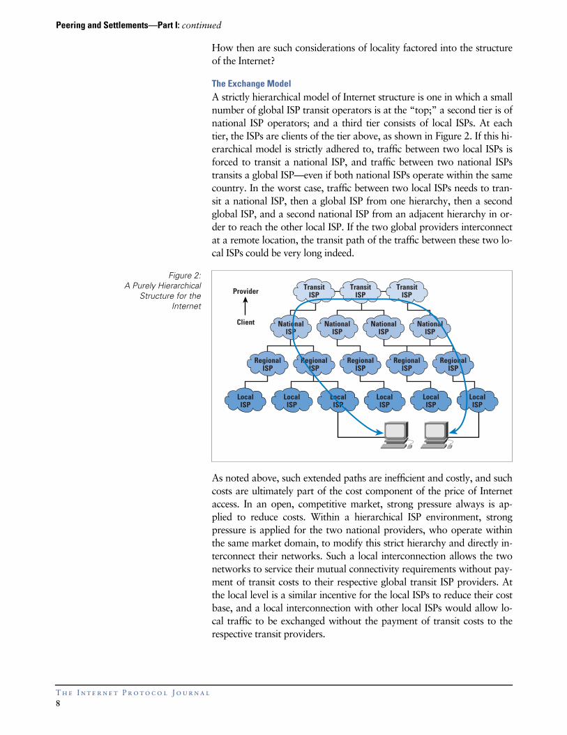
A strictly hierarchical model of Internet structure is one in which a smallnumber of global ISP transit operators is at the “top;” a second tier is ofnational ISP operators; and a third tier consists of local ISPs. At eachtier, the ISPs are clients of the tier above, as shown in Figure 2. If this hi-erarchical model is strictly adhered to, traffic between two local ISPs isforced to transit a national ISP, and traffic between two national ISPstransits a global ISP—even if both national ISPs operate within the samecountry. In the worst case, traffic between two local ISPs needs to tran-sit a national ISP, then a global ISP from one hierarchy, then a secondglobal ISP, and a second national ISP from an adjacent hierarchy in or-der to reach the other local ISP. If the two global providers interconnectat a remote location, the transit path of the traffic between these two lo-cal ISPs could be very long indeed.
Figure 2:A Purely Hierarchical
Structure for theInternet
As noted above, such extended paths are inefficient and costly, and suchcosts are ultimately part of the cost component of the price of Internetaccess. In an open, competitive market, strong pressure always is ap-plied to reduce costs. Within a hierarchical ISP environment, strongpressure is applied for the two national providers, who operate withinthe same market domain, to modify this strict hierarchy and directly in-terconnect their networks. Such a local interconnection allows the twonetworks to service their mutual connectivity requirements without pay-ment of transit costs to their respective global transit ISP providers. Atthe local level is a similar incentive for the local ISPs to reduce their costbase, and a local interconnection with other local ISPs would allow lo-cal traffic to be exchanged without the payment of transit costs to therespective transit providers.
LocalISP
LocalISP
LocalISP
LocalISP
LocalISP
LocalISP
RegionalISP
RegionalISP
RegionalISP
RegionalISP
RegionalISP
NationalISP
NationalISP
NationalISP
NationalISP
TransitISP
TransitISP
TransitISPProvider
Client

T h e I n t e r n e t P r o t o c o l J o u r n a l
9
Although constructing a general interconnection regime based on point-to-point bilateral connections is possible, this approach does not exhibitgood scaling properties. Between
N
providers who want to intercon-nect, the outcome of such a model of single interconnecting circuits is(
N
2
– N
) / 2 circuits and (
N
2
– N
) / 2 routing interconnections, as indi-cated in Figure 3. Given that interconnections exhibit the greatestleverage within geographical local situations, simplifying this picturewithin the structure of a local exchange is possible. In this scenario, eachprovider draws a single circuit to the local exchange and then executesinterconnections at this exchange location. Between
N
providers whowant to interconnect, the same functionality of complete interconnec-tion can be constructed using only
N
point-to-point circuits.
Figure 3:Fully Meshed Peering
The Exchange Router
One model of an exchange is to build the exchange itself as a router, asindicated in Figure 4. Each provider’s circuit terminates on the ex-change router, and each provider’s routing system peers with therouting process on the exchange router. This structure also simplifiesthe routing configuration, so that full interconnection of
N
providers iseffected with
N
routing peer sessions. This simplification does allowgreater levels of scaling in the interconnection architecture.
However, the exchange router model becomes an active component ofthe interconnect peering policy environment. In effect, each providermust execute a multilateral interconnection peering with all of the otherconnected providers. Selectively interconnecting with a subset of the pro-viders present at such a router-based exchange is not easily achieved. Inaddition, this type of exchange must execute its own routing policy.When two or more providers are advertising a route to the same desti-nation, the exchange router must execute a policy decision as to whichprovider’s route is loaded in the router’s forwarding table, making a pol-icy choice of transit provider on behalf of all other exchange-connectedproviders.

Peering and Settlements—Part I:
continued
T h e I n t e r n e t P r o t o c o l J o u r n a l
1 0
Because the exchange is now an active policy element in the interconnec-tion environment, the exchange is no longer completely neutral to allparticipants. This imposition on the providers may be seen as unaccept-able, in that some of their ability to devise and execute an externaltransit policy is usurped by the exchange operator’s policies.
Figure 4:An Exchange Router
Typically, providers have a higher expectation of flexibility of policy de-termination from exchange structures than the base level of functionalitythat is provided by an exchange router. Providers want the flexibility toexecute interconnections on a bilateral basis at the exchange, and tomake policy decisions as to which provider to prefer when the same des-tination is advertised by multiple providers. They require the exchangeto be neutral with respect to such individual routing policy decisions.
The Exchange Switch
The modification to the interprovider exchange structure is to use a lo-cal Layer 2 switch (or LAN) as the exchange element. In this model, aparticipating provider draws a circuit to the exchange and locates a ded-icated router on the exchange LAN, as shown in Figure 5. Each providerexecutes a bilateral peering agreement with another provider by initiat-ing a router peering session with the other party’s router. When thesame network destination is advertised by multiple peers, the providercan execute a policy-based preference as to which peer’s route will beloaded in the local forwarding table. Such a structure preserves the costefficiency of using
N
circuits to effect interconnection at the
N
providerexchange, while admitting the important policy flexibility provided byup to (
N
2
– N
) / 2 potential routing peer sessions.
Early interprovider exchanges were based on an Ethernet LAN as thecommon interconnection element. This physical structure was simple,and not all that robust under the pressures of growth as the LAN be-came congested.
A
Exchange Routerselects preferredpath to destination A

T h e I n t e r n e t P r o t o c o l J o u r n a l
1 1
Figure 5:An Exchange LAN
Subsequent refinements to the model have included the use of Ethernetswitches as a higher capacity LAN, and the use of
Fiber DistributedData Interface
(FDDI) rings, switched FDDI hubs, Fast Ethernet hubs,and switched Fast Ethernet hubs. Exchanges are very-high-traffic con-centration points, and the desire to manage ever-higher traffic volumeshas led to the adoption of Gigabit Ethernet switches as the current evo-lutionary technology step within such exchanges.
The model of the exchange colocation accommodates a model of diver-sity of access media, in which the provider’s colocated router undertakesthe media translation between the access link protocol and the commonexchange protocol.
The local traffic exchange hub does represent a critical point of failurewithin the local Internet topology. Accordingly, the exchange should beengineered in the most resilient fashion possible, using standards associ-ated with a premium quality data center. This structure may includemultiple power utility connections, uninterruptible power supplies, mul-tiple trunk fiber connections, and excellent site security measures.
The exchange should operate neutrally with respect to every participat-ing ISP, with the interests of all the exchange clients in mind. Thus,exchange facilities, which are operated by an entity that is not also a lo-cal or trunk ISP, enjoy higher levels of trust from the clients of theexchange.
There are also some drawbacks to an exchange, and a commonly citedexample is that of imposed transit. If an exchange participant directs adefault route to another exchange router, then in the absence of defen-sive mechanisms, the target router carries the imposed transit traffic evenwhen there is no routing peering or business agreement between the twoISPs. Exchange-located routers do require careful configuration manage-ment to ensure that route peering and associated transit traffic matchesthe currently executed interconnection agreements.
A
RoutePeer Mesh
Bilateral peering allowseach ISP to select preferredpath to destination A

Peering and Settlements—Part I:
continued
T h e I n t e r n e t P r o t o c o l J o u r n a l
1 2
Distributed Exchanges
Distributed exchange models also have been deployed in various loca-tions. This deployment can be as simple as a metropolitan FDDIextension, in which the exchange comes to the provider’s location ratherthan the reverse, as indicated in Figure 6. Other models that use anATM-based switching fabric also have been deployed using
LAN Emu-lation
(LANE) to mimic the Layer 2 exchange switch functionality.Distributed exchange models attempt to address the significant cost ofoperating a single colocation environment with a high degree of resil-ience and security, but do so at a cost of enforcing the use of a uniformaccess technology between every distributed exchange participant.
Figure 6:A Distributed Exchange
However, the major challenge of such distributed models is that ofswitching speed. Switching requires some element of contention resolu-tion, in which two ingress data elements that are addressed to acommon egress path require the switch to detect the resource conten-tion and then resolve it by serializing the egress. Switching, therefore,requires signaling, in which the switching element must inform the in-gress element of switch contention. To increase the throughput of theswitch, the latency of this signaling must be reduced. The dictates of in-creased switching speed have the corollary of requiring the switch toexist within the confines of a single location, if exchange performance isa paramount concern.
In addition to speed, the cost shift must be considered. In a distributedexchange model, the exchange operator operates the set of access cir-cuits that form the distributed exchange. This process increases costs toproviders, while it prevents the providers from using a specific accesstechnology that matches their business requirements of cost and sup-portable traffic volume. Not surprisingly, to date the most prevalentform of exchange remains the third-party hosted colocation model. Thismodel admits a high degree of diversity in access technologies, while stillproviding the substrate of an interconnection environment that can op-erate at high speed and therefore manage high traffic volumes.
Switching Mesh
PeeringVirtualCircuits

T h e I n t e r n e t P r o t o c o l J o u r n a l
1 3
Other Exchange-Located Services
The colocation environment is often broadened to include other func-tions, in addition to a pure routing and traffic exchange role. For a high-volume content provider, the exchange location offers minimal transitdistance to a large user population distributed across multiple local ser-vice providers, as well as allowing the content provider to exercise achoice in selecting a nonlocal transit provider.
The exchange operator can also add value to the exchange environmentby providing additional functions and services, as well as terminatingproviders’ routers and large-volume content services. The exchange loca-tion within the overall network topology is an ideal location for hostingmulticast services, because the location is optimal in terms of multicastcarriage efficiency. Similarly, USENET trunk feed systems can exploitthe local hub created by the exchange. The overall architecture of a colo-cation environment that permits value-added services, which canproductively use the unique environment created at an exchange, is indi-cated in Figure 7.
Figure 7:Exchange-LocatedService Platforms
Network Access Points
The role of the exchange was broadened with the introduction of the
Network Access Point
(NAP) in the architecture proposed by the Na-tional Science Foundation (NSF) in 1995 when the NSFNET backbonewas being phased out.
The NAP was seen to undertake two roles: the role of an exchange pro-vider between regional ISPs who want to execute bilateral peeringarrangements and the role of a transit purchase venue, in which re-gional ISPs could execute purchase agreements with one or more of a setof trunk carriage ISPs also connected at the NAP. The access point con-cept was intended to describe access to the trunk transit service.
Web Cache
Server
MulticastRouter USENET
ServerDNS Root
Server
Web Hosting ServicesRoute Server
Service EnvironmentPeering Environment

Peering and Settlements—Part I:
continued
T h e I n t e r n e t P r o t o c o l J o u r n a l
1 4
This mixed role of both local exchange and transit operations leads toconsiderable operational complexity, in terms of the transit providersbeing able to execute a clear business agreement. What is the band-width of the purchased service in terms of requirements for trunktransit, versus the access requirements for exchange traffic? If a local ISPpurchases a transit service at one of the NAPs, does that imply that thetrunk provider is then obligated to present all the ISP’s routes at remoteNAPs as a peer? How can a trunk provider distinguish between trafficpresented to it on behalf of a remote client versus traffic presented to itby a local service client?
The issue that the quality of the purchased transit service is colored bythe quality of the service provided by the NAP operator should also beconsidered. Although the quality of the transit provider’s network mayremain constant, and the quality of the local ISP’s network and ISP’sNAP access circuit may be acceptable, the quality of the transit servicemay be negatively impacted by the quality of the NAP transit itself.
One common solution is to use the NAP colocation facility to executetransit purchase agreements and then use so-called
backdoor
connec-tions for the transit service provision role. This usage restricts the NAPexchange network to a theoretically simpler local exchange role. Such aconfiguration is illustrated in Figure 8.
Figure 8:Peering and Transit
Purchase
Backdoor Connectionto Transit Service
PeeringDomain
ISP ATransit Domain
Local Exchange
Locally Exchanged Traffic
Remote PeeringDomain
Remote PeeringDomain
Remote PeeringDomain
ISP B

T h e I n t e r n e t P r o t o c o l J o u r n a l
1 5
Exchange Business Models
For the ISP industry, many attributes are considered highly desirable foran exchange facility. The common model of an Internet exchange in-cludes many, if not all, of the following elements:
• Operated by a neutral party who is not an ISP (to ensure fairness andneutrality in the operation of the exchange)
• Constructed in a robust and secure fashion
• Located in areas of high density of Internet market space
• Able to scale in size
• Operates in a fiscally sound and stable business fashion
A continuing concern exists about the performance of exchanges andthe consequent issue of quality of services that traverse the exchange.Many of these concerns stem from an exchange business model thatmay not be adequately robust under pressures of growth from partici-pating ISPs.
The exchange business models typically are based on a flat-fee struc-ture. The most basic model uses a fee structure based on the number ofrack units used by the ISP to colocate equipment at the exchange. Whenan exchange participant increases the amount of traffic presented overan access interface, under a flat-fee structure, this increased level oftraffic is not accompanied by any increase in exchange fees. However,the greater traffic volumes do imply that the exchange itself is faced witha greater traffic load. This greater load places pressure on the exchangeoperator to deploy further equipment to augment the switching capac-ity, without any corresponding increase in revenue levels to the operator.
For an exchange operator to base tariffs on the access bandwidths is notaltogether feasible, given that such access facilities are leased by the par-ticipating ISPs and the access bandwidth may not be known to theexchange operator. Nor is using a traffic-based funding model possible,because an exchange operator should refrain from monitoring individ-ual ISP traffic across the exchange, given the unique position of theexchange operator. Accordingly, the exchange operator has to devise afiscally prudent tariff structure at the outset that enables the exchangeoperator to accommodate large-scale traffic growth, while maintainingthe highest possible traffic throughput levels.
Alternatively, there are business models in which the exchange is struc-tured as a cooperative entity among numerous ISPs. In these models, theexchange is a nonprofit common asset of the cooperative body. Al-though widely used, these models are prone to the economic conditionof the
Tragedy of the Commons.
It is in everyone’s interest to maximizetheir exploitation of the exchange, while no single member wants to un-derwrite the financial responsibility for ensuring that the quality of theexchange itself is maintained.

Peering and Settlements—Part I:
continued
T h e I n t e r n e t P r o t o c o l J o u r n a l
1 6
The conclusion that can be drawn is that the exchange is an importantcomponent of Internet infrastructure, and the quality of the exchange isof paramount importance if it is to be of any relevance to ISPs. Using anindependent exchange operator whose income is derived from the util-ity of the exchange is one way of ensuring that the exchange is managedproficiently and that the service quality is maintained for the ISP clientsof the exchange.
A Structure for Connectivity
Enhancing the Internet infrastructure is quantified by the followingobjectives:
• Extension of reachability
• Enhancement of policy matching by ISPs
• Localization of connectivity
• Backup arrangements for reliability of operation
• Increasing capacity of connectivity
• Enhanced operational stability
• Creation of a rational structure of the connection environment toallow scalable structuring of the address and routing space in order toaccommodate orderly growth
We have reached a critical point within the evolution of the Internet.The natural reaction of the various network service entities in responseto the increasing number of ISPs will be to increase the complexity of theinterconnection structure to preserve various direct connectivity require-ments. Today, we are in the uncomfortable position of increasinglycomplex interprovider connectivity environments, a situation that isstressing the capability of available technologies and equipment. The in-ability to reach stable cost-distribution models in a transit arrangementcreates an environment in which each ISP attempts to optimize its posi-tion by undertaking as many direct 1:1 connections with peer ISPs as itpossibly can. Some of these connections are managed via the exchangestructure. Many more are implemented as direct links between the twoentities. Given the relative crudity of the inter-
Autonomous System
(AS)routing policy tools that we use today, this structure must be a source ofconsiderable concern. The result of a combination of an increasinglycomplex mesh of inter-AS connections, together with very poor tools tomanage the resultant routing space, is an increase in the overall instabil-ity of the Internet environment. In terms of meeting critical immediateobjectives, however, such dire general predictions do not act as an effec-tive deterrent to these actions.
The result is a situation in which the inter-AS space is the critical compo-nent of the Internet. This space can be viewed correctly as the
demilitarized zone
within the politics of today’s ISP-based Internet. Inthe absence of any coherent policy, or even a commonly accepted set ofpractices, the lack of administration of this space is a source of para-mount concern.
GEOFF HUSTON holds a B.Sc and aM.Sc from the Australian NationalUniversity. He has been closelyinvolved with the development of theInternet for the past decade. He wasresponsible for the initial build of theInternet within the Australian academicand research sector. Huston is currentlythe Chief Technologist in the Internetarea for Telstra. He is also an activemember of the IETF, and is a memberof the Internet Society Board of Trust-ees. He is author of
The ISP SurvivalGuide,
and coauthor of
Quality of Ser-vice: Delivering QoS on the Internetand in Corporate Networks
, a collabo-ration with Paul Ferguson. Both booksare published by John Wiley & Sons.E-mail:

T h e I n t e r n e t P r o t o c o l J o u r n a l
1 7
IPv6—What and Where It Is
by Robert L. Fink, Energy Sciences Network
he current Internet Protocol, known as IPv4 (for version 4), hasserved the Internet well for over 20 years, but is reaching thelimits of its design. It is difficult to configure, it is running out of
addressing space, and it provides no features for site renumbering to al-low for an easy change of
Internet Service Provider
(ISP), among otherlimitations. Various mechanisms have been developed to alleviate theseproblems (for example,
Dynamic Host Configuration Protocol
[DHCP]and
Network Address Translation
[NAT]), but each has its own set oflimitations.
The
Internet Engineering Task Force
(IETF) took on this problem in theearly 1990s by starting an IPng (
Internet Protocol next generation
)project. After an over two-year-long process of defining goals and fea-tures, getting the best possible advice from industry and user experts,and sponsoring a protocol design competition, a new Internet Protocolwas selected. Many proposed protocols were reviewed, analyzed, andevaluated. An evolved combination of several of them (
Simple InternetProtocol
[SIP], the
“P” Internet Protoco
l [PIP], and
Simple Internet Pro-tocol Plus
[SIPP]), each using fixed-length addressing, resulted in a finalvariation, called IPv6, which was selected over a version of the ISO OSI
Connectionless Network Protocol
(CLNP) (known as the
TCP andUDP with Bigger Addresses
(TUBA) IPng proposal).
Much work has been done since the selection of IPv6 in 1994. Over 50implementations of IPv6 are believed to be under way or completed. Aconstantly growing international IPv6 testbed, called the
6bone,
nowspans 260 sites in 39 countries, with over 25 different IPv6 implementa-tions in use. Most router companies, including 3Com, Bay, CiscoSystems, Digital, Nokia, and Telebit support IPv6. IPv6 is also availablefor Digital, HP, IBM, Sun, WinTel, and many other end-user hostsystems.
IPv6 Addresses—Larger and Different
The larger 128-bit IPv6 address (versus the 32-bit IPv4 address) allowsmore flexibility in designing newer addressing architectures, as well asproviding large enough address spaces for predicted future growth of theInternet and Internet-related technologies. A new addressing format,called the
Aggregatable Global Unicast Address Format
, has been devel-oped to help solve route complexity scaling problems with the currentIPv4 Internet. The current IPv4 provider-based addressing used in theInternet relies on separate IPv4 addresses being assigned to ISPs in con-tiguously numbered blocks for routing efficiency; that is, the routersneed to carry fewer routes.
T

IPv6:
continued
T h e I n t e r n e t P r o t o c o l J o u r n a l
1 8
However, there is currently much fragmentation in the IPv4 addressspace. This situation, aggravated by sites not being able to easily renum-ber, causes many more separate routes than necessary, in turn leading toroute computation complexity (too many routes, too many dynamicchanges, too much computation in routers).
Public Routing Topology Prefixes
With the new aggregatable style addressing (see Figure 1), the left-most48 bits of the address are defined as a
Public Routing Topology
(PRT)prefix. The first 3-bit field of this prefix specifies that the addressing for-mat is aggregatable. The next 13-bit portion specifies the
Top LevelAggregator
(TLA) ID that constrains the top level of Internet routing to8,192 major transit providers and a new concept of routing exchanges.Each TLA (top level transit ISP) is then responsible for all the remainingpublic routing topology assignment below it; that is, the
Next Level Ag-gregator
(NLA) ID. As shown in Figure 1, the NLA may have a tieredhierarchy to allow multiple levels (NLA1, NLA2, and so on) of otherISPs, each of which would then have control of the assignment of thespace below it. The right-most portion of the NLA field, at whateverlevel it may be, would identify the end-user “leaf” site. An 8-bit re-served field has been defined to allow the growth of either the TLA orthe NLA fields.
Figure 1:Aggregatable Global
Unicast AddressFormat
001 RES NLA Interface IDTLA SLA
3 8 24 6413 16
Public Routing Topology
Downward Delegation of NLA
TLA = Top Level AggregatorNLA = Next Level AggregatorSLA = Site Level Aggregator
RES = Reserved for future useto allow either TLAor NLA growth
Interface IdentifierFormat derived fromEUI-64 with u-bitinverted
EUI-64 formed from48-bit EthernetAddress
Interface IdentifierSite
Topology48
Site ID Interface IDSLANLA1
6416n 24–n
Site ID Interface IDSLANLA2
6416m 24–n–m
Site ID Interface IDSLA
6416
NLA3
o24–n–m–o
“u” Company Code Extension Identifier
644024
Company Code EthernetExtension Identifier
2424
FFFE16
16

T h e I n t e r n e t P r o t o c o l J o u r n a l
1 9
The advantage of this style of addressing is that it allows automatic ad-dress clustering, or aggregation, into a constrained set of routes, whichare represented through the TLA field. If the initial assignment of 13 bits(8,192 TLAs) is insufficient in the future, either the reserved field or an-other piece of the IPv6 128-bit address space could be utilized. Note thatonly one-eighth of the current IPv6 address space has been assigned toaggregatable addressing.
Even with this new concept of addressing, sites will still occasionallywant to change their ISP (as in the current IPv4-based Internet) and thuswill need to readdress to keep the addressing structure constrained. Thisis where
Site Renumbering,
which will be discussed later, comes in.
IPv6 TLA Assignment
To begin the production use of IPv6, ISPs providing IPv6 service need tobe assigned TLAs so they may assign NLAs to transits and sites they areserving. Until recently, this was not possible. Recent discussions be-tween the IETF, the IANA (
Internet Assigned Numbers Authority
), andthe major address registries (APNIC, ARIN, and RIPE-NCC), have re-sulted in agreements that will provide a way to request and assign TLAsby early 2nd quarter 1999.
The process agreed upon is based on the above discussions that havebeen published as a recommendation in an Informational RFC on TLAassignments. The basic idea is to provide a slow start mechanism forTLAs by assigning one TLA ID to be used for defining a Sub-TLA fieldof 13 bits out of the reserved and NLA fields (see Figure 2). This will al-low transits to demonstrate their need for a full TLA based on usage ofthe assigned Sub-TLA. These rules, based on much current practice withIPv4, are necessary to keep aggregatable addressing functional and ef-fective for hierarchical routing as IPv6 comes into use.
Figure 2:Sub-TLA Format for
IPV6 AddressAssignment
Rules for assigning these Sub-TLAs include:
• Must have a plan to offer native IPv6 service within three monthsfrom assignment; must have a verifiable track record providing Inter-net transit to other organizations
• Must make payment of a registration fee to the IANA and reason-able fees for services rendered by the address registry
• Must maintain registries of sites and next-level providers and makethem available publicly and to the registries; must provide utilizationstatistics of NLA space below the assigned TLA (or Sub-TLA) andalso show evidence of carrying TLA routing and transit traffic
001 Interface IDTLA
0x0001
3 6413
Sub-TLA
13
SLA
16
NLA
19
SUB-TLA IDs are assigned out of TLA ID 0x0001 as shown above.
Note that use of the Reserved field to create the Sub-TLA field is specific to TLA ID 0x0001.It does not effect any other TLA.

IPv6:
continued
T h e I n t e r n e t P r o t o c o l J o u r n a l
2 0
These rules are intended to minimize route explosion and address as-signment misuse to aid in the stability of the IPv6-based Internet.
Site Topology Prefixes
In addition to identifying the address of the site with the PRT prefix, ag-gregatable addressing provides for a site to have aggregation as wellusing a 16-bit
Site Level Aggregator
(SLA). The SLA might be as simpleas a subnet number (more than 64,000 of them!), or a tiered hierarchysuch as the NLA provides. However it is structured, the SLA is underthe control of the site, and identifies the subnet that a host interface is at-tached to (IPv6’s addressing, as IPv4’s, specifies interfaces on systems,not the entire system).
It is very unlikely that an organization will ever need more than onePRT prefix, given the size and flexibility of the SLA and the
System In-terface Identifier
field (described below).
System Interface Identifiers
Now that we have identified how to reach the site and the subnet a sys-tem is attached to, an interface identifier (ID) specifies the local logicaladdress of the interface on the local subnet (or
link
as it is often called).The interface ID is formed and derived from the new IEEE EUI-64 me-dia-level address that is an expansion of the well-known Ethernet 48-bitaddress format that allows for more device identifiers to be assigned byeach manufacturer. The global/local bit is also inverted to make manu-ally assigned (that is, local) addresses easy to form with only leadingzeros.
If the IPv6 node is attached to an Ethernet “link,” then the 48-bit ad-dress is turned into 64 bits by a filler field inserted in the middle (seeFigure 1).
This enlarged Interface ID will allow newer technologies, such as
FireWire
, and newer applications, such as traffic lights and PCS/PDAtelephones, to have unique interface identifiers assigned to them from aglobal address space.
The use of a media-level address for a network-level Interface ID allowsthe very important IPv6 Stateless Address Autoconfiguration Protocol towork.
Stateless Address Autoconfiguration
Automatic configuration of IPv6 end systems (hosts) is one of the mostimportant features of IPv6. In the current IPv4 Internet, you must eithermanually configure IP address, network mask, and default gateway, orrely on having a DHCP server. With IPv6, this process can take placeautomatically, with no reliance on outside systems, using the IPv6
State-less Address Autoconfiguration Protocol
.

T h e I n t e r n e t P r o t o c o l J o u r n a l
2 1
This can be done because the
Media Access Control
(MAC) address isused to form the host’s interface ID. For example, if a host has an Ether-net interface that it is trying to configure for use with IPv6, the 48-bitEthernet MAC address is formed into a 64-bit interface ID, which is theright-most 64 bits of the IPv6 address (see Figure 1). Then, using the
Neighbor Discovery
(ND) protocol, which is unique to IPv6, thisformed interface ID is checked to see that it does not have a duplicate onthis link (that is, subnet). If it does, a randomly generated token can beused (though a rare occurrence, it is a necessary protection against ille-gal Ethernet address usage and situations where the same address maybe used on multiple interfaces for legitimate reasons).
At this point, an
ND Router Solicitation
multicast message is sent out todiscover if there is a local IPv6 capable router, what the local site’s to-pology ID for the host’s subnet is, and what the site’s public topologyrouting prefix is. Neighbor Discovery can also be used to controlwhether the site then wishes to continue with further configuration us-ing Stateful Autoconfiguration with DHCPv6.
IPv6 Autoconfiguration thus provides for standalone operation of twoor more hosts on a local LAN link with no router present, provides foroperation within a site with no outside Internet connectivity present, andallows for easy changing of the site’s public topology routing prefix, ei-ther when external connectivity comes on line, or when the externalconnectivity is changed, such as when a different ISP is chosen.
Domain Name System—Forward and Reverse
The
Domain Name System
(DNS) is an essential component of the In-ternet. To provide a mapping from a domain name to an IPv6 address,as well as an IPv4 address, a new DNS record type of “AAAA,” or“quad A,” is defined. This is a clever word play on the “A” record typethat the original DNS specification defines for 32-bit IPv4 addresses, be-cause IPv6 addresses are four times larger (128-bits), hence “AAAA”!
Most existing implementations of DNS already support AAAA recordsand existing IPv4 queries of DNS can access these records; that is, youdon’t need a DNS operating over IPv6 to retrieve these new AAAArecords. This support also includes reverse lookups, similar to IPv4s, al-though a new reverse lookup proposal that will allow automaticpartitioning of the delegation information on arbitrary bit boundaries isunder consideration. This new capability should make for more reliablereverse registry than exists with IPv4, and easier maintenance when siteschange their PRT prefix.
When a host with both IPv4 and IPv6 operating on it (“dual stack”)queries the DNS for the address of a remote host, the A and AAAArecords returned are used to indicate what protocol to use in communi-cating with that remote host. If no AAAA record is returned, IPv4 mustbe used. If only a AAAA record is returned, IPv6 must be used. If bothA and AAAA are returned, either IPv4 or IPv6 may be used.

IPv6:
continued
T h e I n t e r n e t P r o t o c o l J o u r n a l
2 2
A new modification of the IPv6 DNS extensions is nearing completionthat allows the automatic joining of the routing prefixes and InterfaceIDs when a host’s IPv6 address is returned, thus making it easier to re-number a site. This new IPv6 DNS feature makes changing a site’s PRTprefix (renumbering) very easy as only one entry, the PRT prefix, needsto be changed. This setup also facilitates easy support of multiple ad-dresses for each host. These enhancements are very useful; IPv4 does nothave this feature.
Renumbering Sites When ISPs Change
Because IPv6 addressing is based on the PRT prefix assigned by its ISP,it is essential that it be easy for a site to renumber itself when its choiceof ISP changes. To aid in this, a new
Router Renumbering
(RR) proto-col, in conjunction with Autoconfiguration, Neighbor Discovery and thenew Aggregatable Unicast addressing PRT prefix are used.
RR allows a site’s network administrator to set new PRT prefixes intothe site’s routers, as well as lower the lifetime of existing ISP PRTprefixes to specify an overlap interval, after which the old ISP’s service isdiscontinued.
Hosts learn their new routing prefixes either when they restart, and thusare automatically configured with Autoconfiguration, or when they areinformed by their local router that a new prefix is to be used during peri-odic router notification updates using ND.
For example, a new ISP service is readied for service while the old ISP isnotified that it will provide service for just 60 more days. After the newPRT prefix is announced to the site’s routers by RR, hosts will use thenew prefix (that is, new ISP) for all new connections, while existing con-nections continue to work until the old prefix is withdrawn (that is, after60 days in this example).
The easy renumbering of an IPv6 site will make easy a task that is cur-rently very painful for an IPv4 site because hosts are often manuallyconfigured in many networks.
The 6bone—An IPv6 Testbed
The 6bone is an international IPv6 testbed network that is overseen anddirected through the IETF
IPng Transition Working Group
(ngtrans)that provides:
• Testing of IPv6 implementations and standards
• Testing of IPv6 transition strategies
• A place to gain early applications and operations experience
• Motivation and a place for implementers, users, and ISPs to try IPv6
• An experimental first step toward transition

T h e I n t e r n e t P r o t o c o l J o u r n a l
2 3
In the early phases of IPv6 deployment, most native IPv6 transport is re-stricted to site LANs with the ability to experiment with it locally. Somesites in Great Britain, The Netherlands, and Japan are using native IPv6over WAN links.
ISPs and various other private IPv4 transit providers may not place IPv6in their production routers in this early phase of IPv6 deployment, leav-ing early IPv6 testers with the need to use the existing IPv4 Internetinfrastructure to deliver IPv6 packets among themselves when remotelylocated. Thus an IPv6 transition feature, IPv6 encapsulation (that is,
tun-neling
) over IPv4, is used for parts of the 6bone where native IPv6 maynot be available. In this way, the 6bone is also thoroughly testing out itsown transition technology as well as providing IPv6 service.
The 6bone is a diverse community of users, ISPs, and developer organi-zations, many of whom provide transit on the public spirited basis ofpromoting and gaining early experience with IPv6. It is expected thatproduction variations of the 6bone will also be created to more for-mally carry production IPv6 traffic.
Components of the 6bone
The 6bone provides this needed IPv6 transport over the public Internetinfrastructure, relying on:
• Dual IPv4/IPv6 stacks in the client host
• IPv6 packets encapsulated (tunneled) in IPv4 packets
• Dual IPv4/IPv6 stack backbone routers that know IPv6 routes of6bone participants
• DNS that supports IPv6 AAAA records
• A 6bone Routing Registry to keep track of sites and their tunnels
• A mailing list, various IPv6 tools, and a 6bone Web site at:
www.6bone.net
Figure 3 shows a conceptual overview of how a basic 6bone is struc-tured and a picture of the current 6bone backbone structure can be seenat:
http://www.cs-ipv6.lancs.ac.uk/ftp-archive/6Bone/Maps/full-backbone.gif
…with the pseudo TLA site-to-site peering indicated by various coloredlinks.
To date, the 6bone has spread to 260 organizations in 39 countries (seeTable 1 on page 25).

IPv6:
continued
T h e I n t e r n e t P r o t o c o l J o u r n a l
2 4
Figure 3:6bone Conceptual
Architecture
6bone History
Serious work to evolve and refine the IPv6 protocols sufficient to allowthe start of various implementations of IPv6 began in 1994. By early1996, it was obvious that a testing environment was needed, so inMarch 1996, several implementers and users met and agreed to start aninternational testbed called the 6bone.
By June 1996, two groups raced to provide the first IPv6 connectivity:the University of Lisbon (Portugal), the Naval Research Laboratory(U.S.), and Cisco Systems (U.S.); a Danish universities consortium (UNI-C), a French universities consortium (G6), and a Japanese universitiesconsortium (WIDE).
6bone backbonerouters connected
with IPv4 “tunnels” thatuse BGP4+ between them
to establish routes
IPv4 Internet
IPv6 overIPv4 manuallyconfigured“tunnel” tonearest6bone router
With this 6bone architecture, once an IPv6-capable test sitehas an IPv6 over IPv4 “tunnel” to a 6bone backbone router,then any IPv6 packet directed to it will be delivered to theappropriate 6bone site
6bone Registryof sites, address
delegationsand routes
Router w/Dual Stack
User Hostw/Dual Stack
Internet ApplicationTCP
IPv4 IPv6
OS and Net Drivers
User Hostw/Dual Stack
Internet ApplicationTCP
IPv4 IPv6
OS and Net Drivers
DNS at host’ssite to record“AAAA” IPv6
addresses

T h e I n t e r n e t P r o t o c o l J o u r n a l
2 5
6bone Backbone and Addressing
By the end of 1997, the 6bone converted to the new aggregatable ad-dressing format, a change necessitated by having originally adopted anearly prototype provider-based addressing format discussed during earlyIPv6 design efforts.
Along with the change to a new addressing format was the need to cleanup the routing used among the 6bone backbone transit sites. It was orig-inally thought that IDRPv6 (a new Internet Domain Routing Protocolbased on earlier IPv4 work) would be the prevailing
Exterior GatewayProtocol
(EGP) used for IPv6 Internet peering.
By mid 1996, various ISPs made it known that a new EGP for IPv6 wasnot a practical alternative, given the explosive growth of the Internetand the current evolution and widespread use of the
Border GatewayProtocol 4
(BGP4) by ISPs. There was a need to allow for multiprotocolextensions to BGP4, allowing ISPs to more easily adapt their operationsto IPv6. This situation led to the rapid evolution of BGP4+, an exten-sion of BGP4 to include IPv6 and IPv4 multiprotocol routing.
By mid 1997, the decision was made to convert the 6bone backbone toBGP4+ for its EGP. See
http://www.cs-ipv6.lancs.ac.uk/ftp-ar-chive/6Bone/Maps/full-backbone.gif
for a recent picture of the6bone backbone sites using the new aggregatable addressing format andthe current status of the conversion to BGP4+.
Table 1: Countries with Sites Participating in the 6bone
AT-Austria FI-Finland NL-The Netherlands
AU-Australia FR-France NO-Norway
BE-Belgium GB-United Kingdom PL-Poland
BG-Bulgaria GR-Greece PT-Portugal
BR-Brazil HK-Hong Kong RO-Romania
CA-Canada HU-Hungary RU-Russian Federation
CH-Switzerland IE-Ireland SE-Sweden
CM-Cameroon IT-Italy SG-Singapore
CN-China JP-Japan SI-Slovenia
CZ-Czech Republic KR-Korea SK-Slovakia
DE-Germany KZ-Kazakhstan TW-Taiwan
DK-Denmark LT-Lithuania US-United States
ES-Spain MX-Mexico ZA-Zaire

IPv6:
continued
T h e I n t e r n e t P r o t o c o l J o u r n a l
2 6
6bone Future Plans
To date, most 6bone efforts have been to prove out basic IPv6 interoper-ability among the many implementations, and to create a reliableinternational testbed infrastructure. This has included making its back-bone operationally ready with the new aggregatable addressing formatand use of BGP4+ for high-reliability routing and transit.
Now that the 6bone has completed these conversions, serious work canbegin on testing site renumbering, security, applications, and transitionmechanisms.
Other IPv6 Trials and Testing
Other testing venues have also been very important to the evolution ofIPv6: the University of New Hampshire
Inter Operability Laboratory
(IOL), various trade show demonstration networks, for example, Net-World+Interop, and various vendor-sponsored interoperability testing.
By early 1998, the UNH IOL had hosted five IPv6 test sessions, thoughspecific details about participating vendors are not released.
In a positive sign of industry response to evolving IPv6 specifications, thelate July 1997 UNH testing resulted in the successful interoperability ofall participants using the new aggregatable addressing format, no morethan two months from its first Internet Draft.
Implementations
To date, over 50 different IPv6 host and router implementations are ei-ther completed or under way. More than 30 implementations have beentested and used on the 6bone.
Router implementations to date include: 3Com, Bay, Cisco Systems,Digital, Fujitsu LR550, Hitachi NR60, Inria BSD, Linux, Merit MRT,Nokia, NRL for BSD, Telebit, WIDE KAME and ZETA for BSD, andWIDE v6d.
Host implementations to date include: Apple MacOS OpenTransportdemo version, Digital OpenVMS, Digital UNIX, FTP SoftwareWindows95, Fujitsu LR450, 460, and 550, Hitachi NR60, IBM AIX,Inria BSD, Linux, HP-UX (SICS), Microsoft Research WindowsNT ver-sions 4 and 5, Sony CSL Apertos IPv4/v6 stack, Sun Solaris, TrumpetWinsock for IPv6, UNH for BSD, NRL for BSD, WIDE KAME andZETA for BSD, and WIDE v6d.
Several new Windows implementations that will operate underWindows95/98/NT are under way.

T h e I n t e r n e t P r o t o c o l J o u r n a l
2 7
Transition from IPv4 to IPv6—A Seamless Approach
IPv6 is unlikely to become the Internet network-layer protocol of choiceunless there is literally no choice to be made by the end user, little effortby network and system administrators, and it can operate alongsideIPv4 for the indefinite future. Therefore, it must be very easy for the pri-vate network (your corporate net) and public network (your ISP)operators to equip, enable, and operate IPv6, while operating IPv4, insuch a way that the user doesn’t notice that IPv6 is there at all.
A system administrator, but not the user, must be conscious of IPv6 in aminimal sense. It is just another protocol stack that any Internet-basedapplications will operate over if the system is configured and distributedto do so by the system administrator.
At the network operator level, IPv6 is just another routing stack that caneasily be turned on in the site’s and ISP’s routers (many sites certainlysupport IPX, AppleTalk, DECnet,...). IPv6 interdomain routing can beoperated just like IPv4s because it uses BGP4+.
With the aid of the new
Dynamic DNS Registration Protocol
and IPv6’sStateless Autoconfiguration, users can boot up their system after it hasbeen enabled with an IPv6 stack, in addition to its IPv4 stack, and be-come IPv6-ready without being aware of it at all. The system wouldautomatically be configured with an IPv6 address, have itself registeredautomatically in the DNS with the host’s existing name alongside itsnew IPv6 address (in addition to its DNS IPv4 address registration), andwhen finding a remote host with IPv6, start talking IPv6—all this with-out the user being required to consciously take action.
Early Production IPv6 Networks
In October of 1998, the
6REN
initiative, was established by the U.S. En-ergy Sciences Network (ESnet). The 6REN is a voluntary coordinationinitiative of
Research and Education Networks
(RENs) that provideproduction IPv6 transit service to facilitiate high quality, high perfor-mance, and operationally robust IPv6 networks.
The first participants were ESnet (the U.S. Dept. of Energy’s Energy Sci-ences Network), Internet2 (the advanced Internetworking developmentcollaboration comprised of many large U.S. research universities), CA-NARIE (the Canadian joint government and industry initiative foradvanced networking), vBNS (the MCI network for NSF advanced net-working) and WIDE (the Japanese research effort to establish a “WidelyIntegrated Distributed Environment”).
Other profit and not-for-profit networks worldwide have been invited tojoin the 6REN. It is expected that during 1999 a sizable production en-vironment capable of advanced demonstrations and deployment ofInternet applications over IPv6 networks will be in place.

IPv6:
continued
T h e I n t e r n e t P r o t o c o l J o u r n a l
2 8
The Future for IPv6
It is too early to predict with total certainty that the Internet will adaptto the use of the IPv6 protocol. However, it should be obvious that IPv6offers many important features for a next-generation Internet: auto-matic configuration, greatly expanded addressing, easy site renumber-ing, built-in security, and more.
One possible scenario for IPv6 is where it becomes the protocol ofchoice for newer applications not currently using Internet technology;for example, controlling traffic lights, reading electric meters, and so on.In these uses, IPv6 does not require coexistence with IPv4 because someform of gateway function would provide interconnection to the currentInternet.
Another scenario (which doesn’t exclude the previous one) is that Mi-crosoft provides IPv6 support for a future version of WindowsNetworking on Windows OS, and promotes it within corporate Amer-ica for its better features in supporting advanced corporate application/networking needs. In this scenario, the Internet will learn to carry IPv6somehow, even if it is via automatically created tunnels that operateover IPv4 (somewhat similar to the 6bone’s tunneling, but with dy-namic creation of the tunnels as needed). It is expected that afterMicrosoft ships IPv6 and large corporations begin using it, ISPs will de-ploy IPv6 to get their business.
Yet another possibility is that the Internet telephony revolution willcome to the conclusion that only IPv6 can provide cost-effective, scal-able, end-to-end worldwide telephony implementations. This may beeven more important as new classes of wireless networked devices, forexample, PDAs and PCS phones, are integrated and built in very largevolume.
Also, in parts of Asia and China, where there is little Internet connectiv-ity at present, and very few IPv4 addresses assigned, IPv6 may becomevery popular because it will allow rapid growth without concerns aboutaddress space.
The probability is high that not just one of the above scenarios will hap-pen, but that all will occur, in addition to others not yet imagined.
Whatever the implementation scenario, the probability that IPv6 willaugment IPv4 as a part of the Internet of the future is very high!

T h e I n t e r n e t P r o t o c o l J o u r n a l
2 9
References
[1] IPng and IPv6 information, including formal specifications can be foundat:
http://playground.sun.com/pub/ipng/html/
[2] 6bone information, including diagrams, hookup info, and registryaccess is at:
http://www.6bone.net
[3] An IEEE EUI-64 overview can be found at:
http://standards.ieee.org/db/oui/tutorials/EUI64.html
[4] “Internet Protocol, Version 6 (IPv6) Specification,” RFC 2460,December 1998.
[5] “Neighbor Discovery for IP Version 6 (IPv6),” RFC 2461, December1998.
[6] “IPv6 Stateless Address Autoconfiguration,” RFC 2462, December1998.
[7] “Internet Control Message Protocol (ICMPv6) for the Internet ProtocolVersion 6 (IPv6),” RFC 2463, December 1998.
[8] “IP Version 6 Addressing Architecture,” RFC 2373, July 1998.
[9] “An IPv6 Aggregatable Global Unicast Address Format,” RFC 2374,July 1998.
[10] “DNS Extensions to support IP version 6,” RFC 1886, December 1995.
[11] “Proposed TLA and NLA Assignment Rules,” RFC 2374, December1998.
[12] “Transition Mechanisms for IPv6 Hosts and Routers,” RFC 1933,April 1996.
[13] “Router Renumbering for IPv6,” Internet Draft, Work in Progress,
draft-ietf-ipngwg-router-renum-06.txt
, November 1998.
[14]
IPv6: The New Internet Protocol,
Christian Huitema, ISBN 0-13-850505-5, Prentice Hall, 1998.
[15]
IPng: Internet Protocol Next Generation,
Edited by Scott O. Bradnerand Allison Mankin, ISBN 0-201-63395-7, Addison-Wesley, 1996.
ROBERT FINK is a network researcher with ESnet (the U.S. Dept. of Energy’sEnergy Sciences Network) at the Berkeley Lab (the Ernest Orlando LawrenceBerkeley National Laboratory). He is cochair of the IETF ngtrans (IPng Transition)Working Group, and leads the 6bone project. You can reach him at:

T h e I n t e r n e t P r o t o c o l J o u r n a l3 0
Secure E-Mail: Problems, Standards, and Prospectsby Marshall T. Rose and David Strom
s we spend more and more time using e-mail, most of us even-tually find that we need to be able to prove our identity to ourcorrespondents and secure the contents of our messages so that
others can’t view them readily. Proving your identity is called authentica-tion. In the physical world, this is accomplished by photo identification,such as a driver’s license, passport, or corporate identity card. When thetime comes to prove who you are (for example, before a major pur-chase), you show your card. Your appearance and signature match thephoto and signature on your card, and the purchase is made.
On the Internet, however, the process isn’t as easy. Does e-mail [email protected] really originate from our friend Sidney at the Ex-ample Corporation? Maybe it’s from someone else, who just happens tobe using Sidney’s machine when he is out to lunch. Or, worse, someonetrying to impersonate Sidney illicitly. And even if the message actually isfrom the “real” Sidney, how can we be sure: Is there an electronic ana-log to a signature?
Most of us are trusting individuals; we tend to believe that people arewho they say they are unless we have particular reasons to doubt theiridentity. But on the Internet, we have to look beyond face value. Andproving that someone indeed did send a particular message is a verydifficult problem.
This may be one of the main reasons why corporations employ LotusNotes and other Internet-based messaging systems that are not 100-per-cent pure. They want to ensure that all messages carry the appropriateauthentication with them at all times. In order for new users of Notes tostart using the software, they must first obtain an electronic certificatethat authenticates them to the system. The certificate is created by theNotes system administrator, who works in conjunction with that partic-ular Notes server owned by that particular corporation.
Securing the message contents is also a challenge: all e-mail sent over theInternet, unless otherwise protected, is sent in clear ASCII text. If youhave the tools, the time, and the technical expertise, you can capture thistraffic and read anyone’s correspondence. It isn’t simple, but it is quitepossible.
Besides being sent as clear text, e-mail can also be intercepted and itscontents changed between the time the sender composes the messageand the recipient reads it. Again, this task is neither likely nor simple,but it can be accomplished if someone is determined enough to do it.Therefore, senders can neither prove nor deny that they sent a particu-lar message to you; it could be real or a forgery, and you have no way ofknowing which.
A

T h e I n t e r n e t P r o t o c o l J o u r n a l
3 1
Cryptography Standards
It would be great if we could say that the future for secure e-mail isbright, and that there will be standards in place that will help. How-ever, the state of secure e-mail standards for the Internet is bestdescribed as a “terrible mess”! (Ed.: a less charitable phrase is used inthe book from which this material is adopted.) Think that characteriza-tion is unprofessional? It is actually quite detached, considering theamount of culpability enjoyed by the principals of the Internet’s securee-mail debacle. We would love to write an article describing the highcrimes and misdemeanors of these scoundrels, but that would only pub-licize the guilty, not punish them. So, instead we’ll survey the horizonand try to make sense of what little terrain there is.
[1]
In brief, no technologies for secure e-mail in the Internet meet all of thefollowing criteria:
• Multivendor
• Interoperable
• Approved or endorsed by the Internet’s standardization body
There are two competing technologies, each of which satisfies at mostone of these criteria. However, for any 100-percent-pure Internet solu-tion to succeed, we feel it must be based on technologies that satisfy allthree.
Basic Concepts
In order to understand secure e-mail, you need to know only threeconcepts:
• Data encryption (privacy)
• Message integrity (authentication)
• Key management
Everything else is a matter of data formats.
Data Encryption
When the contents of a message are to be protected from third-partydisclosure, it is necessary to agree upon an encryption algorithm. Be-cause cryptographic algorithms are constantly being scrutinized, asecure e-mail standard must be extensible with respect to the algo-rithms that it allows.
Historically,
symmetric encryption algorithms
are used for this purpose.A symmetric algorithm is one in which the same key is used to both en-crypt and decrypt the data. Symmetric algorithms are chosen becausethey are computationally less burdensome (in other words, faster to exe-cute) than asymmetric algorithms.

Secure E-Mail:
continued
T h e I n t e r n e t P r o t o c o l J o u r n a l
3 2
As such, each time a message is to be encrypted, a new session key isgenerated for that purpose. Although one could send the session key viasome secure path, it is easier to include the session key along with themessage, but encrypted so that only the intended recipient can decipherit. Upon deciphering the session key, the recipient can apply the encryp-tion algorithm and retrieve the original contents.
For example, Network Associates’ Pretty Good Privacy (PGP), one ofthe two technologies we’ll examine, uses an asymmetric algorithm to en-crypt the session key and a symmetric algorithm to encrypt the user’sdata.
Message Integrity
When the contents of a message are to be verified as authored by a par-ticular user and unaltered by any other user, it is necessary to agreeupon a
signature
and
hash
algorithm
. The former is used to verify theauthenticity of the message, and the latter is used to verify the integrityof the message. Again, any secure e-mail standard must be extensiblewith respect to the algorithms that it uses for these purposes.
For signature algorithms, asymmetric algorithms are typically used.These algorithms utilize a public key and a secret key. A signature algo-rithm combined with a secret key allows someone to generate a digitalsignature for the contents of a message. A signature algorithm com-bined with a public key allows someone to verify the digital signaturefor a message. As you might expect, signature algorithms are one-wayfunctions: You can’t reconstruct the input to a signature function bylooking at its output.
Hash algorithms are often called
message digest algorithms
. They sim-ply compute a checksum on their input; no keys are involved. Hashalgorithms are also one-way functions, and a good hash algorithm isone in which very similar inputs produce dramatically different outputs.Hence, if even a single bit is altered or corrupted in transit, the hashvalue will be different.
Key Management
All discussion now hinges on how keys are used for asymmetric algo-rithms. Specifically, how do you trust the identity of the secret key usedto make a digital signature? To start, we have to introduce the notion ofa
public key certificate
. Although the actual formats vary, at its heart acertificate contains three things:
• The identity of the “owner” of the certificate
• A public key
• Zero or more guarantees to the validity of the binding between theidentity contained in the key and the owner in the “real world”

T h e I n t e r n e t P r o t o c o l J o u r n a l
3 3
So, the next step is to ask what these identities and guarantees looklike. Unfortunately, we now enter the realm of sociology rather thantechnology. The only theoretical limitation on an identity is that youhave to be able to represent it digitally. It could be a name (for exam-ple, “Jim Bidzos”) or an e-mail address (for example,
) ora key in some database (for example, the name of an object in a direc-tory). More interesting examples could include a series of assertions(for example, your driver’s license number is this, your passport num-ber is that, and so on).
Fortunately, the guarantees are a bit simpler to describe—they are digi-tal signatures from other public keys that vouch for the veracity of thebinding. For example, if you encountered a public key certificate inwhich the identity was someone’s passport number, it would be naturalto expect that the certificate contains a digital signature from the govern-ment entity (or its agent) that issued the passport. However, this begsanother question: Why should you trust the entities that have signedsomeone’s public key? It turns out that our two contending technolo-gies have different answers to that question.
As you might expect, certificates have some additional properties, suchas a date the certificate becomes valid, the date the certificate expires,and a “fingerprint.” The fingerprint is simply a hash of the identity andpublic key so you can tell if it has been altered in transit.
Finally,
certificate revocation lists
identify certificates that are no longervalid. For example, if the secret key associated with a certificate is acci-dentally disclosed, then the corresponding certificate is revoked.
Pretty Good Privacy: The Web of Trust
Pretty Good Privacy
(PGP) is encryption for the masses. Despite the factthat it required a couple of complete rewrites in order to achieve stabil-ity, it gets the job done.
An effort is under way to provide a “standards-based” version of thePGP technology, termed
OpenPGP.
The “pre-standards” version ofPGP uses the RSA algorithm for signatures and the IDEA algorithm forencryption. The version being developed is more flexible with respect tothe algorithms it supports.
The most remarkable thing about PGP is its trust model. Remember theearlier question: How do you know whether you should believe theidentity in a public key certificate? To answer this in the context of PGP,each user assigns two attributes to the PGP certificates that they encoun-ter:
trust
and
validity
. Trust is a measure as to how accurate thecertificate’s owner is with respect to signing other certificates. Validityindicates whether or not you think the identity in the certificate refers tothe certificate’s owner.

Secure E-Mail:
continued
T h e I n t e r n e t P r o t o c o l J o u r n a l
3 4
So, initially your local collection of certificates starts out with one—yourown PGP certificate. You then sign your friend’s certificate and he or shesigns yours. Because you trust yourself when signing those certificates,your friend’s certificates are automatically considered valid. Then, basedon your judgment of your friend’s abilities to sign other certificates accu-rately, you assign a level of trust to his or her PGP certificates. As youreceive messages containing other people’s certificates, if they are signedby you, or any of your trustworthy friends, they are automaticallydeemed valid. This organic, highly decentralized approach toward vali-dating public key certificates is termed the
web of trust
.
Key servers are also available that are repositories of PGP certificates. Ifyou need to send e-mail to someone, but don’t have his or her certificate,you can query a server to see if a copy is there. Of course, the usual rulesapply with respect to assigning trust and validity—it’s up to you! Keyservers also help when you receive e-mail from someone new. Althoughthe message will contain a copy of someone’s PGP certificate, you maynot know about any of the signatories. So, you can go to a key serverand fetch the certificates for the signatories; you might decide to trustthem after seeing who signed their certificates.
We’ve simplified the web of trust in that validity isn’t “all or nothing,”as we implied previously. Rather, PGP offers a flexibility spectrum ofpossibilities; for example, requiring two trustworthy signatories beforeconsidering a certificate to be valid. But the one thing that should beclear is that trust and validity are
different
. You will probably havemany keys in your local collection of certificates that are consideredvalid, but probably only a few of those will be considered authorized tovouch for others.
Secure MIME: The Hierarchy of Trust
There is an interesting concept in advertising called “ambush market-ing.” The basic idea is that your advertising campaign leverages off thebrand and promotion of a competitor.
Secure Multipurpose InternetMail Extensions,
or S/MIME, is an example of ambush marketing in theInternet. Although MIME is an Internet standard, which has been im-plemented by hundreds of vendors and provisioned in tens of thousandsof networks, S/MIME is the product of a closed vendor consortium.
S/MIME has two versions: version 2 and version 3. As of this writing,products that claim to implement S/MIME implement version 2. Theyuse the RSA algorithm for signatures and a weak algorithm for encryp-tion (RC2 with 40-bit keys). An effort is under way to provide a“standards-based” version of the S/MIME technology—version 3. Theversion being developed is more flexible with respect to the algorithms itsupports. S/MIME uses a hierarchical model for establishing trust. Forexample, if your employer assigns you an S/MIME certificate, he will actas a certification authority and sign that certificate. As a consequence,trust is established on the basis of a hierarchical relationship between the
subject
of a certificate (the identity) and the
issuer
(the signatory).

T h e I n t e r n e t P r o t o c o l J o u r n a l
3 5
This model has some strengths: users rely on the certification authoritiesimplicitly. However, a bootstrapping problem still exists: How do youknow to trust the issuer? The answer is that your local collection ofcertificates also has some “top-level” certificate authorities, and it isthese authorities that sign the public key certificates of the issuers. If thehierarchy of trust can be kept to one or two levels, this is manageable inpractice.
The web and hierarchical models of trust share many attributes in com-mon. For example, when you receive a message, it contains a copy ofthe certificate that was used to make the digital signature. If you aren’tfamiliar with the signatories, you can look in a remote repository ofkeys. The only difference between the two models here is that the hierar-chical model needs key servers to make its key infrastructure work.Because of this, keys are usually stored in a directory service accessed viathe
Lightweight Directory Access Protocol
(LDAP).
Data Formats
The
multipart/encrypted
and
multipart/signed
contents are usedto convey secure e-mail. Fortunately, they are both very simple contenttypes.
A
multipart/signed
content has two subordinate body parts. Thefirst contains the data that is being authenticated and can be any MIMEcontent type (
text/HTML
,
multipart/mixed
, and so on). The secondcontains the digital signature used to authenticate the content. The
mul-tipart/signed
content has two mandatory parameters. The
protocol
parameter defines the technology used to generate the digital signature,and the
micalg
(for “MIC algorithm”) parameter defines the hashing al-gorithm used (for “MIC” read:
message integrity check
). The value ofthe protocol parameter is also the content type used for the second bodypart. The only tricky part is that the digital signature is calculated on thedata before a transfer encoding, if any, is applied.
Let’s make this a little more concrete. If we assume that the OpenPGPeffort produces an Internet standard based on the current draft (a rea-sonable assumption at 50,000 feet), then the structure of a
multipart/signed
message created using PGP technology would look like thefollowing:
• The protocol parameter would be
application/pgp-signature
• The micalg parameter would be
pgp-md5
• The first body part would be labeled as whatever you wanted to sign
• The second body part would labeled as
application/pgp-signature
The second body part, a data structure defined by the OpenPGP docu-ment, contains the digital signature along with any supporting material(for example, a copy of the sender’s PGP certificate).

Secure E-Mail:
continued
T h e I n t e r n e t P r o t o c o l J o u r n a l
3 6
Note that you don’t encrypt the first body part in a
multipart/signed
content. In this way, if only some of your recipients have secure e-mail,but you still want to sign it for those who do, everyone can still read thefirst body part.
A
multipart/encrypted
content has two subordinate body parts. Thefirst contains the information needed to decipher the encrypted data (forexample, the encrypted session key along with an indication as to thecertificate needed to decipher the session key). The second contains theencrypted data, labeled as
application/octet-stream
. The
multi-part/encrypted
content has one mandatory parameter, protocol,which defines the technology used to encrypt the data. The value of theprotocol parameter is also the content type used for the first body part.
To further define this concept, if we use OpenPGP as the basis for a hy-pothetical example, then the structure of a
multipart/encrypted
would look like the following:
• The protocol parameter would be
application/pgp-encrypted
• The first body part would be labeled as
application/pgp-encrypted
• The second body part would labeled as
application/octet-stream
In practice, the input to the encryption algorithm would be
multipart/signed.
Finally, one or more MIME content types might be definedfor sending certificates, certificate revocation lists, and so on. These areall specific to the particular secure e-mail technology being used.
Encrypting Your Messages
If we look at popular commercial e-mail products, many of them in-clude support for some kind of encryption. Both Microsoft’s OutlookExpress and Netscape Messenger include support for S/MIME, al-though we’ll see in a moment that the two have radically differentcapabilities. And Qualcomm’s Eudora Pro package comes with an add-on module for supporting PGP, which you may or may not have in-stalled when you installed the software. In order to encrypt a message,you need to go through the following process:
1. Choose which of the two competing technologies (and specific e-mailsoftware) you wish to use for your encrypted correspondence. Bothmethods have advantages and disadvantages.
2. Choose whether you want to just digitally sign your messages orencrypt their entire contents, or both.
3. Either choose an enterprise certificate authority and set up the appro-priate server software, or obtain a certificate from a public authority.Again, both methods have advantages and disadvantages.
4. Enroll with this certificate authority and obtain an encryptioncertificate or key for a particular machine and a single e-mail address.

T h e I n t e r n e t P r o t o c o l J o u r n a l
3 7
5. Exchange keys with your correspondents, and manage where thesekeys are stored on your machine.
6. Encrypt and decrypt messages.
If this process seems rather involved and complex, it is. The process isnot nearly where it should be to enable encryption to be useful by moste-mail users, and won’t be for some time. If all of this seems overwhelm-ing to you, we certainly understand.
[2]
It is to us, too! But let’s gothrough these six steps in more detail.
PGP vs. S/MIME
Our discussion in the standards section might have convinced you thatencryption technology is still very much a work in progress, and afteryou begin to use the encryption features of your own e-mail software,you’ll be further convinced. Nevertheless, unless you plan to test lots ofdifferent software products, you should first decide on which productand which encryption technology you intend to use. You definitely wantto limit yourself to as small a universe as possible, because running morethan one e-mail software product will only make your encryption lifemiserable. So which to choose?
PGP is everyman’s product. It was designed for single individuals to useand still remains the easiest method to set up and get going, although itis far from simple. The version of PGP that comes with the Eudora Probox is the individual version; a separate and more capable version isavailable for workgroups or businesses, called
PGP for Business Secu-rity
. This business version is the one we recommend, even if you are theonly person in your corporation that will use encryption. You’ll findthat after you start, others will follow, and you might as well start offwith the more capable version.
If you want to use PGP, you will need to run a separate piece of soft-ware to encrypt and decrypt your messages. If you already use softwaresuch as Messenger or Outlook Express, that is certainly more cumber-some than using the built-in S/MIME features of those two products.
In 1999, PGP is more capable than S/MIME when it comes to setting upan enterprise encryption policy and putting it into practice on a daily ba-sis. For example, with PGP you could establish that all outgoing andincoming encrypted messages are first copied to a special archive, andthat all outgoing messages are encrypted with a special administrator’skey that can be used in an emergency to read the message if the senderforgets his key or leaves the company. S/MIME doesn’t have this abilityyet, although this feature is being developed for the future.
PGP is a single-vendor solution: All your software must eventually comefrom Network Associates to run the various certificate servers and en-cryption modules. With S/MIME, you’ll have some degree of choice,although we found that in practice you probably want to make use of

Secure E-Mail:
continued
T h e I n t e r n e t P r o t o c o l J o u r n a l
3 8
the same e-mail product when exchanging encrypted messages if youwant them to be read with a minimum of difficulty. Not all S/MIMEpackages can exchange encrypted messages with each other because ofdifferences in their implementations. When Dan Backman of
NetworkComputing
magazine tested five different products, he found severalthat couldn’t read messages sent by others.
[3]
Part of the problem with S/MIME is the various choices of “strength” ofcryptographic algorithms that are in use in today’s browsers and e-mailsoftware. This debate is more about politics than technology, becausethe U.S. government places restrictions on various algorithms, as men-tioned earlier. Two different parameters are of interest: the length of thekey itself used in any certificate and the type of encryption technologyused. Netscape software supports key lengths ranging from 512 to 1024bits, for example. In addition, several choices are available for encryp-tion technology; they are labeled
RC2
(which can either be 40-bitencryption, the only one allowed for export by the U.S. government, ormore complex encryption of 64, 128, or even 255 bits), and
Data En-cryption Standard
(DES). RSA, Inc., developed RC2. On the other hand,the U.S. government developed DES. Debate abounds as to which is thebetter or more or less proprietary technology.
These details are outside the scope of this article, but you should knowthat the larger the key size and encryption algorithm, the more difficultit is for someone to decode an intercepted message.
Digital Signature Required?
Your next choice is to consider whether to just make use of a digital sig-nature, to encrypt the entire message, or to make use of bothtechnologies. All encryption products can do both, but in somewhat dif-ferent ways.
Digital signatures guarantee that your recipients have received your mes-sage without any tampering and that they can trust that the messagecame from you. The actual message body, and any attachments, arrivewithout any encryption, meaning that someone could still capture thistraffic and read your correspondence. You might want to use a digitalsignature without encrypting the message, if you care that your messagewas received intact and that your correspondents can know that yousent it.
There are two different types of signed messages:
clear
and
opaque
.With clear-signed messages, you can still read the message text, even ifyou don’t have any encryption functions in your e-mail software. Thesignature is carried along with the message in a separate MIME portionof the message from the message body, which remains untouched andstill readable. This feature can be handy, especially if you correspondwith many people and they probably haven’t adopted any particular en-cryption product, or if they are using older versions of e-mail softwarethat don’t support encryption.

T h e I n t e r n e t P r o t o c o l J o u r n a l
3 9
Clear signing is also useful in circumstances where your encryption tech-nology isn’t compatible with your correspondents’ technology. PGPsupports only clear signing in its products.
One problem with clear signing is e-mail gateways. They often willbreak the encryption of the signature, because they will either add or re-move characters from the message, and that sloppiness could invalidatethe signature block. After all, part of the role of the signature is to en-sure that the message was delivered intact and unaltered!
Opaque signing means that your recipients will get a blank message ifthey aren’t running any encryption software, or if their encryption soft-ware doesn’t work with yours. Opaque signing wraps the entire messagein a Base64 encoding, which is usually left alone by most e-mail gate-ways. This encoded message then gets transmitted and then decoded bythe S/MIME recipient.
PGP places its signature inside the encrypted envelope when it sendsmessages, making it difficult to determine the signature of such a mes-sage until you first decrypt it. The PGP producers claim that this featureoffers extra protection in case the message is compromised or copied enroute. Newer versions of PGP offer a MIME option that places the sig-nature outside the encrypted envelope. This is how S/MIME productswork, making it easier to determine who sent it.
Choose Your Certificate Authority
Now you have another decision to face, and that is how to set up whatis called the
certificate authority
(CA) for your enterprise. This softwareruns on a UNIX or NT server and manages the keys or certificates of ev-eryone in your corporation. It serves as a central place of trust and signsall of your users’ certificates. If you trust your CA, in theory you shouldbe able to trust the certificates that are signed by the CA, called
inher-ited trust.
The problem is that there isn’t any “central” CA for the entire universeof e-mail users. Although there are several public CAs that anyone canuse, either for free or for a fee, they don’t necessarily trust each other,nor should they. What happens if an employee of VeriSign becomes dis-gruntled and starts issuing bad certificates? There should be checks andaudits to ensure that these types of problems can’t undermine the entireCA system, just as there are checks and audits to prevent rogue bankingemployees from crediting their own accounts.
Setting up a CA is the beginning of setting up a very complex security in-frastructure for your enterprise. Your CA needs to establish a link oftrust from all your users to the administrator or operator of the CA it-self, and from your CA to other CAs with which you communicate.

Secure E-Mail:
continued
T h e I n t e r n e t P r o t o c o l J o u r n a l
4 0
There are two different kinds of CAs: One uses software that you installon your own server inside your enterprise and you maintain; the other ispublic servers. Having your own server places the burden on creatingand revoking certificates on your security administrator, or whoever isgoing to operate the CA server. In many cases, these products can be ad-ministered from a Web browser after they are installed, and the serverscan handle certificates from a wide variety of S/MIME products, one ofthe few shining spots on the interoperability scene at the moment.
PGP for Business comes with its own version of a certificate server. Itruns on a Windows desktop machine and typically is used by the admin-istrator of the entire security apparatus to handle certificates. It canhandle only PGP certificates.
Some popular software products that function as certificate servers arelisted below.
Enroll and Acquire Your Certificate
When you have your certificate authority either in mind or installed, younext have to set up how you want to acquire your own certificate.
You have two broad methods: by Web or by e-mail. Actually, you don’thave any choice: If you have picked your e-mail product and CA at thispoint in the process, you have to use whatever method comes with thatchoice. Netscape Messenger and Microsoft’s Outlook Express, amongothers, make use of their related Web browsers to enroll certificates, asyou might suspect. And other products make use of e-mail to send andenroll certificates. For example, Xcert’s Sentry CA sends you a messagetelling you that your certificate has been granted, but in the e-mail it hasURLs for both Communicator and Internet Explorer where you candownload the certificate and place it inside the appropriate software.Why two different links? Because each product supports a different wayof acquiring certificates, of course. So much for standards.
Vendor URL Product
Enterprise CAs:
NetscapeXcert
www.netscape.comwww.xcert.com
Certificate ServerSentry CA
Public CAs:
VeriSignThawte
www.verisign.comwww.thawte.com
Secure Server IDPublic CA

T h e I n t e r n e t P r o t o c o l J o u r n a l
4 1
Exchange and Manage Certificates
Now comes the hard part—dealing with the certificates of your corre-spondents, and managing both theirs as well as other certificates aroundyour corporation.
As we mentioned in our standards section, you need to exchangecertificates with your correspondents before you can begin to exchangeencrypted e-mail. And that means sending your public key to them, andgetting their public keys from them, before you can exchange actual en-crypted messages. If you are corresponding with someone who doesn’thave the same CA in common, you’ll first need to establish a trust rela-tionship and exchange root CA certificates before you can exchange theindividual certificates. This is somewhat painful, but when you get thehang of it, it isn’t that difficult.
After you begin to exchange more than a few of these certificates, youmight think that this is a job for a directory server, and, thankfully, thevendors are already there. The CA server can set up entries in an LDAPdirectory to keep track of who is issued a certificate, and you can querythis LDAP server to find who has them. That is the good news, and in-deed the PGP product makes use of its own LDAP server to keep trackof its certificates. However, the LDAP server is only used by PGP; if youwant a general-purpose LDAP server to keep track of your users, you’llhave to install something else.
As a challenge for open systems and interoperability, we installed theXcert Sentry CA and Netscape’s Directory Server on a test network. TheXcert was used to create and manage our certificates for our test corpo-ration, and the entries were placed in the Netscape LDAP directory. Wecreated the certificates using the Netscape browser and stored the infor-mation in our Messenger e-mail software. After going through theprocess described previously, we had a valid certificate and could see itin the Security|Messenger settings. Although the Sentry CA couldn’t au-tomatically deposit a certificate in the Netscape LDAP server, we(operating as the security administrator) could do so with a few simpleWeb forms and keystrokes. So far, so good.
The challenge was trying to pry these certificates loose using other prod-ucts, such as Outlook Express. There we ran into trouble, mainlybecause the Netscape software creates the certificate in a nonstandardplace in the LDAP directory. According to the standards documents, thecertificate should be placed in a particular spot in the LDAP directoryschema, called
usercertificate.
Netscape, for whatever reason, placesthem at a location called
usersmimecertificate.
This meant that non-Netscape products couldn’t view the certificates in our directory, be-cause they were looking in the wrong place.

Secure E-Mail: continued
T h e I n t e r n e t P r o t o c o l J o u r n a l4 2
This brings up a very good point: The connection between a user andhis or her certificate is tenuous at best. Just because you know [email protected] is the e-mail address of David Strom and you havehis certificate, it doesn’t mean that any of your expensive software toolscan make this connection. This situation will create all sorts of head-aches for your security administrators, and it means that you need tomaintain at least two directories on your own machine—one for usersand one for certificates.
It would be nice if the address books of our e-mail software could han-dle this automatically, but they don’t.
That’s not the only issue with managing certificates. What if someoneleaves the company? Or changes his or her e-mail address? Or if youwant to use the same certificate, but on several different machines? Mostcertificates are tied to a particular machine and a particular e-mail ad-dress, meaning that any new address will require a new certificate.Again, we find this situation unacceptable.
Encrypt and Decrypt Messages Now you can finally go and encrypt your messages. Various options areavailable in your e-mail software to do this, and you can choose to signa message as well as to encrypt it.
That is the encryption portion. What about the decryption side? If youhave done your homework and exchanged certificates as we discussedearlier, then when you receive your encrypted message, it should auto-matically decrypt and display in plain text. You shouldn’t have to doanything else—unless the encryption system is broken by a gateway orproduct incompatibility.
Futures The obvious question is whether the Internet needs two standards for se-cure e-mail.
Proponents for both sides can make superficially compelling arguments.PGP proponents point to a grassroots constituency and a huge installedbase of legacy systems. PGP emphasizes privacy for individuals. S/MIMEproponents, on the other hand, point to some major vendors and an em-phasis on nonrepudiation.
If history is any judge, the PGP side will win because less infrastructureis required to make it work. S/MIME has to solve all the problems thatPGP has to solve, plus a few more. However, these things aren’t decidedovernight. So, our prediction is rather straightforward: The two sideswill compete in the Internet marketplace for a couple of years, but ulti-mately the game is PGP’s to lose. It requires less infrastructure and fewerbroad agreements to achieve ubiquity.

T h e I n t e r n e t P r o t o c o l J o u r n a l4 3
Endnotes [0] Our thanks to Dan Backman of Network Computing magazine for his
help in sharing his lab and providing many valuable insights in thepreparation of this article. This article is based, in part, on InternetMessaging: From the Desktop to the Enterprise, ISBN 0-13-9786100-4Prentice-Hall, 1998.
[1] See http://strom.com/places/smime.html for details regardingproduct interoperability testing for encrypted e-mail packages.
[2] There is an alternative to this process. The United Parcel Service hasproduced a file transfer utility called NetDox, available atwww.netdox.com. It requires special software to be installed on eachcomputer, and it simplifies the certificate and encryption processsomewhat. But this is yet another proprietary solution to the encryptede-mail problem—something we think goes in the wrong direction.
[3] The article has more in-depth examination of testing MIMEinteroperability and features of Messenger, Outlook Express,Baltimore’s MailSecure, OpenSoft’s ExpressMail, and twoWorldtalk plug-ins for Eudora and Outlook Express. See “SecureE-Mail Clients: Not Quite Ready for S/MIME Prime Time. StayTuned.” Network Computing, February 1, 1998,techweb.cmp.com/nc/902/902r2.html.
MARSHALL T. ROSE is Chief Technology Officer of MessageMedia Inc. (formerlyFirst Virtual Holdings, Inc.). He is responsible for the design, specification, andimplementation of several Internet-standard technologies and is an author of over 60of the Internet’s RFCs, and several books on Internet technologies. He can bereached at [email protected]
DAVID STROM is an independent consultant and frequent speaker atNetWorld+Interop shows around the world, where he teaches a class on e-commerceand Web storefronts. He was founding editor-in-chief of Network Computingmagazine and has written over a thousand articles for various computer tradepublications. He is also publisher of the e-mail newsletter Web Informant, an almost-weekly series of essays on Web marketing, technology, and culture. He can bereached at [email protected]

T h e I n t e r n e t P r o t o c o l J o u r n a l4 4
Book ReviewIP Multicasting IP Multicasting: The Complete Guide to Interactive Corporate Net-
works, by Dave Kosiur, ISBN 0-471-24359-0 Wiley ComputerPublishing, 1998, http://www.wiley.com/compbooks/kosiur
There is nothing remarkable about the statement: As technologybecomes more affordable, applications once limited to power users findtheir way to the mainstream desktop. Video streaming, audio stream-ing, collaborative applications, and videoconferencing are all examplesof applications once found exclusively on high-end workstations butnow making their way to the mainstream desktop. If widespreaddeployment of these applications is to occur, we must be prepared tosupply a supporting infrastructure.
The use of IP multicasting is gaining popularity, but many of the funda-mentals that drive this and other network technologies, such as routingprotocols and transport protocols, are still being debated. This booksupplies a comprehensive view of the state-of-the-art as well as practi-cal procedures one can follow in order to incorporate mulitcasting intoexisting network topologies.
OrganizationChapter 2 presents an introduction to TCP/IP basics and routing. Chap-ter 3, The Basics of Multicasting, addresses three sender-based multi-casting protocols (ST-II, XTP, and MTP) and concentrates on IP multi-cast (a receiver-based multicasting protocol). The book would be mucheasier to follow if this chapter had been combined with Chapter 6.
Chapter 4, Multicast Routing Concepts, Chapter 5, Multicast RoutingProtocols, and Chapter 6, Transport Protocols, constitute the heart ofthis book.
Beginning with basic concepts of unicast routing and routing algo-rithms, the author extends the models to deal with the problems ofrouting multicast data. Tree maintenance techniques form the bulk ofChapter 4.
Chapter 5 covers four multicast routing protocols: Distance VectorMulticast Routing Protocol (DVMRP); Multicast Open Shortest PathFirst (MOSPF); Protocol Independent Multicast (PIM); and Core-Based Trees (CBT). Placing the emphasis on PIM, Kosiur covers bothPIM-SM (sparse mode) and PIM-DM (dense mode). He does a nice jobof describing each of the protocols and summarizes each by reviewingits advantages and disadvantages. Finally, the author concludes byexamining ways of achieving interdomain routing and protocolinteroperability.

T h e I n t e r n e t P r o t o c o l J o u r n a l4 5
In Chapter 6, Kosiur provides an overview of the Real-Time TransportProtocol (RTP)/Real-Time Transport Control Protocol (RTCP) and theReal-Time Streaming Protocol (RTSP).
In addition, he discusses a dozen or more multicast protocols, all tryingto answer the question: “How is retransmission of lost packets han-dled?” He classifies the protocol approaches into receiver-based orsender-based. In my opinion, this is the most interesting problem ofmulticasting. Answer this question wrong, and you find yourself with anonscalable network cluttered with acknowledgments (ACKs).
Chapters 4 through 7 all consider delivering Quality of Service and so Iwas a little surprised to see Chapter 7 devoted to the subject.
Kosiur provides a good introduction to RSVP (Resource ReserVationProtocol), but until we see RSVP in wide deployment I would look atthe previous three chapters for practical knowledge on the topic. InChapter 7, and then in Chapter 11 he covers a lot of practical issuesconcerning Quality of Service, as well as ways to support multicastingover various networks, such as ATM, Frame Relay, and ISDN/dialupnetworks.
Chapter 9 is a compilation of some free and commercial software pack-ages that use multicasting. Chapter 10 covers Mbone (the Multicastbackbone), a popular experimental multicasting network. It is arguablethat the state of multicasting wouldn’t be where it is today without theMbone.
A C+This book rates a C+. Kosiur certainly has an understanding of thematerial, but his descriptions are neither clear nor concise. Reading thisbook is difficult, and learning from it even more so, but better organiza-tion could turn it into a gem.
—Neophytos IacovouUniversity of Minnesota
Academic & Distributed Computing [email protected]

T h e I n t e r n e t P r o t o c o l J o u r n a l4 6
Letter to the EditorI just read the September 1998 issue of The Internet Protocol Journaland thoroughly enjoyed it. It was well written with excellent technicaldetail but more importantly, the contributors wrote in an understand-able and organized method. This is not always the norm for goodtechnical resources; so many times it is simply the reprint of a vendor’sdocumentation.
“What is a VPN—Part II,” written by Paul Ferguson and Geoff Hus-ton, was a great article which described the various components andmethodologies of VPNs. The information and explanation of the Vir-tual Private Dial Networking implementations, voluntary versuscompulsory tunneling, subscriber’s perspectives and real world applica-tions clarified my understanding and knowledge on this subject. I alsoappreciate an article that ends with a conclusion. I have already locatedPart I of this article and will be reading it soon. There is one comment; itwould be interesting to know which vendor when an example is used,regarding specifically the Frame Relay service provider.
The “Reliable Multicast Protocols and Applications” article was usefuland informative, including the scaling issues and the information regard-ing the new reliable multicast protocols. The details of the Pretty GoodMulticast (PGM) protocol and how it may improve scaling for multi-cast was very interesting.
The Gigabit Ethernet book review written by Ed Tittel was one of themost informative and well structured book reviews that I have read, es-pecially in a smaller publication. Thanks for providing three pages forbook reviews in a forty-seven page publication. This review provided allthe information that would assist with the determination of purchasingthe book or not.
I hope you continue to publish IPJ in hard copy. I do read and gather in-formation from the Web like everyone else, but I prefer a physical copyto carry with me if I am traveling or at my home. Thanks again for agreat publication and I can hardly wait for the next issue.
—Joe [email protected]
Ed.: We appreciate your comments about our publication. Regardingyour question about the Frame Relay example, it is our policy to avoidas much as possible any discussion of products, but we encourage read-ers to contact the authors directly for that kind of information.
We certainly plan to continue the print edition of IPJ. We are also devel-oping a companion Web site (at www.cisco.com/ipj) that will containadditional information such as glossaries, links to other documents, up-dates, corrections, and so on. Thanks for writing.
—Ole [email protected]

T h e I n t e r n e t P r o t o c o l J o u r n a l4 7
FragmentsICANN UpdateBack in the summer of 1997, the Clinton Administration decided that itwas time to privatize the remaining Internet functions that were beingmanaged within the federal research establishment, mostly dealing withInternet names and addresses. These functions had been handled verysuccessfully over many years by the Internet Assigned Numbers Author-ity (IANA) under the direction Dr. Jon Postel and his staff at theInformation Sciences Institute of the University of Southern Californiaunder contract to DARPA. But it was clear from the rapid expansion ofthe Internet, the emergence of important players on the industry side,and rising controversy over issues such as Network Solutions’ monop-oly in issuing domain names for .com, that change was necessary.
After two major policy papers and months of argumentative debate, thegovernment recognized the Internet Corporation for Assigned Namesand Numbers (ICANN) as the new body to assume responsibility forthese largely technical management functions. Working from plansdrawn up by Dr. Postel, his advisors and the Jones Day law firm,ICANN is endeavoring to satisfy the many constituencies that seek avoice in future decisions on Internet naming and addressing. Sadly, Jondied last fall just as his plan was approaching endorsement by the fed-eral government.
The young organization, incorporated at the end of September, 1998,began operation in early November, has an initial Board of nine ap-pointed Directors headed by Chairman Esther Dyson, and an interimPresident/CEO Mike Roberts. They are responsible for completing orga-nizational details, devising a representation structure for electing theirsuccessors, and beginning to deal with a backlog of undone policy work,such as a determination on if, how and when new top level domains(TLDs) will be created. The new Board has Directors from six countriesand plans to hold meetings quarterly in locations throughout the world,beginning with Singapore in March, 1999 and Berlin in May, 1999.
Being neither a Congressionally chartered corporation nor an industrytrade association, but something in between, ICANN is an internationalorganization that faces a tough political future with many skeptics chal-lenging the notion that the Internet community can successfully governitself in the important naming and addressing area. But with a startupfund from corporate contributions, Chairman Dyson and PresidentRoberts, both short timers by design, are determined to get ICANN offthe ground and into operation in coming months. More information isavailable at: www.icann.org
This publication is distributed on an “as-is” basis, without warranty of any kind either express orimplied, including but not limited to the implied warranties of merchantability, fitness for a particularpurpose, or noninfringement. This publication could contain technical inaccuracies or typographicalerrors. Later issues may modify or update information provided in this issue. Neither the publisher norany contributor shall have any liability to any person for any loss or damage caused directly orindirectly by the information contained herein.

The Internet Protocol JournalOle J. Jacobsen, Editor and Publisher
Editorial Advisory BoardDr. Vint Cerf, Sr. VP, Internet Architecture and EngineeringMCI WorldCom, USA
David Farber The Alfred Fitler Moore Professor of Telecommunication Systems University of Pennsylvania, USA
Edward R. Kozel, Sr. VP, Corporate Development Cisco Systems, Inc., USA
Peter Löthberg, Network ArchitectStupi AB, Sweden
Dr. Jun Murai, Professor, WIDE Project Keio University, Japan
Dr. Deepinder Sidhu, Professor, Computer Science & Electrical Engineering, University of Maryland, Baltimore County Director, Maryland Center for Telecommunications Research, USA
Pindar Wong, Chairman and PresidentVeriFi Limited, Hong Kong
The Internet Protocol Journal is published quarterly by the Cisco News Publications Group, Cisco Systems, Inc.www.cisco.comTel: +1 408 526-4000E-mail: [email protected]
Cisco, Cisco Systems, and the Cisco Systems logo are registered trademarks of Cisco Systems, Inc. in the USA and certain other countries. All other trademarks mentioned in this document are the property of their respective owners.
Copyright © 1999 Cisco Systems Inc.All rights reserved. Printed in the USA.
The Internet Protocol Journal, Cisco Systems170 West Tasman Drive, M/S SJ-J4San Jose, CA 95134-1706USA
ADDRESS SERVICE REQUESTED
Bulk Rate MailU.S. Postage
PAIDCisco Systems, Inc.