mark i series brake - southern-tool.com from the same measurement, or when scoring all your blanks...
TRANSCRIPT

AccessoriesAdjustmentsCapacitiesExploded/PartsInstalling legsMaintenanceMaking HemsMaterial StopsSetup/BendingWheel KitsAdditional Products
................pg 4...............pg 3
..................pg 3...........pg 7
.............pg 5...............pg 6.............pg 3............pg 3............pg 2
..................pg 6.....pg 8
“The Workhorse”
Mark I Series™
Contractor Model
Mark I Series™ Brake Contractor ModelCommercial Model
“Products Engineered to Bring Out the best in Your Work”
Contents:
User’s Guide

Brake Setup
The bending handle assembly shown above comes with handle brackets which are pre-installed. Back off thumb screws far enough to clear front hinge flange and slide assembly onto front hinge. Tighten thumb screws firmly once handle is in desired position. To adjust handle position, loosen both thumb screws, move handle to new location and tighten thumb screws.
Place handle ends into bracket openings and align holes in brackets with holes in handle. Insert screws through holes and tighten snugly with hex nuts. Once you have both handles in place, the brake is ready for use.
2
1
Note: For forming standard fascia, pro-ceed to step 6. For enhanced fascia, first determine orientation of brick mold or rib placement in blank. Lock blank evenly in brake and run TrimFormer along piece.
As described on page 4, make hem in material. Next, with finish side down, bend the hemmed lower leg of fascia profile to 90°. Note: Use the Profile strip to check each step for accuracy.
Complete fascia profile by removing piece from brake and reinserting with the finish side down and the top edge extending outward from the brake. Bend top leg until it matches roof pitch.
2
Material Setup and Bending Basic Shapes
Measure the length of the trim piece. Be sure to add for corner or end laps. If trim piece length exceeds the length of the brake, measure for two pieces and determine best point for overlap.
Measure the width of the trim piece and where each bend will be made. Tech tip: Use a small strip of the material and hand bend it into a profile of the area your trimming off. You can also use the “profile” to check the rest of the job where the same trim piece is to be used.
Lay out material from coil and score along desire trim length*. Next, score along desired width. Transfer the bend-ing information to the scored material (“blank”). With the finish side of the material as your reference, remember to indicate bends up and bends down
3
Measure Length of Trim piece 1 2Measure Total Width
Score Material
Hem(see page 4)
Example of Profile
Brick Mold(see page 5)
ShingleLip
54
Optional Trim Enhancement Step
6

3
Using the Material Back Stops
Open mouth of brake and insert tape against each stop block. Align desired measurement on tape with stainless edge. If using QuickScore™ scoring tool, align measurement to outer edge of vinyl strip.
Vinyl Strip Edge
Stop Block
StainlessEdge
Tighten thumb screw to lock the stop block in place. Repeat tightening of opposite stop block and recheck measurements using the tape rule.
1 2With the mouth of the brake still open, insert material up to both stop blocks and lock in place. Periodically check measurements to ensure stop block hasn’t moved.
3
Using the material back stops can save a considerable amount of time when either making numerous bends from the same measurement, or when scoring all your blanks at once before actually bending trim.
Bending Standard 3/4” Hem
Align edge of material even with edge of vinyl strip (approximately 3/4” from stainless edge). Lock in place. Note: When making odd-sized hems, place marks in material and align with stainless edge.
Bend material around the stainless edge as far as possible. When bending stiffer materials, release pressure and bend again to account for “spring-back”. Note: If hemming heavier material, flatten hem between clamping surfaces using the locking handle before going to step 3.
Remove material from brake and re-lock clamping surfaces. Place hem edge between vinyl strip and stainless edge. With one hand maintaining piece in posi-tion, Bend hem leg snug to material.
1 2 3Stainless
Edge
Vinyl Strip EdgeHem Leg
Adjusting Adjusting Cam WedgesVan Mark Brakes are designed to lock onto the thickness of the material and seldom require adjustment. If material is slipping while bending, or not bending evenly, follow these steps to correct: 1. Lock 6”x6” test piece of material under each casting starting at one end of brake. Move piece side to side along each casting to determine if castings are providing equal resistance. 2. After determining adjustments are needed, loosen wedge screw and move wedge forward in 1/8” increments until you have equal pressure at all castings. Also bend full piece to ensure material isnot slipping or warping during bend.
Screw
Bending Capacities
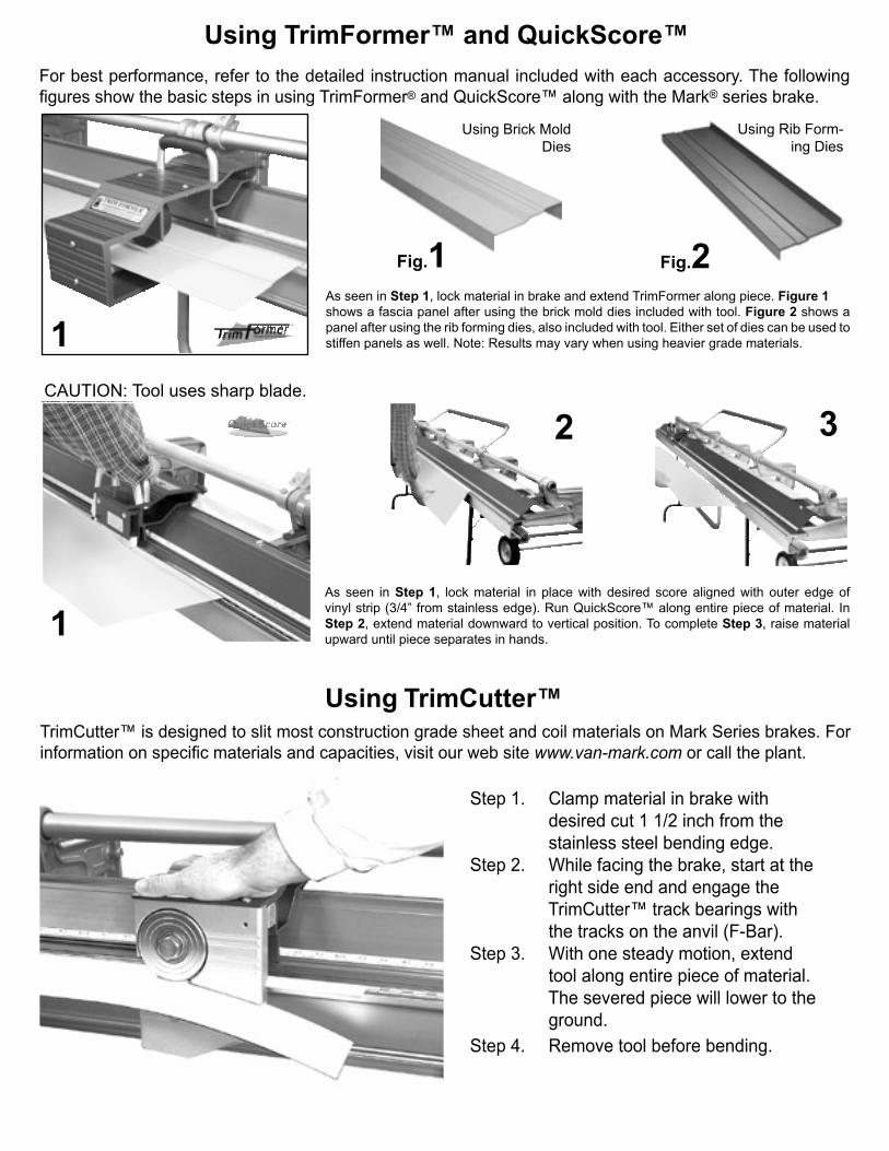
Using TrimFormer™ and QuickScore™For best performance, refer to the detailed instruction manual included with each accessory. The following figures show the basic steps in using TrimFormer® and QuickScore™ along with the Mark® series brake.
As seen in Step 1, lock material in brake and extend TrimFormer along piece. Figure 1shows a fascia panel after using the brick mold dies included with tool. Figure 2 shows a panel after using the rib forming dies, also included with tool. Either set of dies can be used to stiffen panels as well. Note: Results may vary when using heavier grade materials.
1
2
As seen in Step 1, lock material in place with desired score aligned with outer edge of vinyl strip (3/4” from stainless edge). Run QuickScore™ along entire piece of material. In Step 2, extend material downward to vertical position. To complete Step 3, raise material upward until piece separates in hands.
3
1
Fig.1 Fig.2
Using Brick MoldDies
Using Rib Form-ing Dies
CAUTION: Tool uses sharp blade.
4
Using TrimCutter™TrimCutter™ is designed to slit most construction grade sheet and coil materials on Mark Series brakes. For information on specific materials and capacities, visit our web site www.van-mark.com or call the plant.
Step 1. Clamp material in brake with desired cut 1 1/2 inch from the stainless steel bending edge.Step 2. While facing the brake, start at the right side end and engage the TrimCutter™ track bearings with the tracks on the anvil (F-Bar).Step 3. With one steady motion, extend tool along entire piece of material. The severed piece will lower to the ground.Step 4. Remove tool before bending.
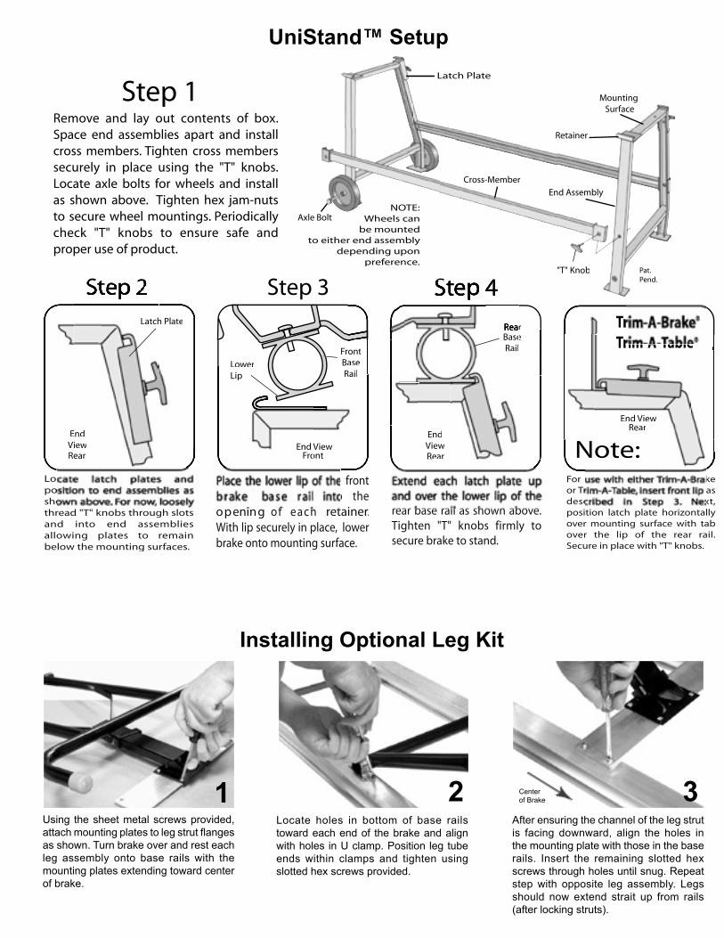
Installing Optional Leg Kit
1 2 3Using the sheet metal screws provided, attach mounting plates to leg strut flanges as shown. Turn brake over and rest each leg assembly onto base rails with the mounting plates extending toward center of brake.
Locate holes in bottom of base rails toward each end of the brake and align with holes in U clamp. Position leg tube ends within clamps and tighten using slotted hex screws provided.
After ensuring the channel of the leg strut is facing downward, align the holes in the mounting plate with those in the base rails. Insert the remaining slotted hex screws through holes until snug. Repeat step with opposite leg assembly. Legs should now extend strait up from rails (after locking struts).
Centerof Brake
Remove and lay out contents of box. Space end assemblies apart and install cross members. Tighten cross members securely in place using the "T" knobs. Locate axle bolts for wheels and install as shown above. Tighten hex jam-nuts to secure wheel mountings. Periodically check "T" knobs to ensure safe and proper use of product.
End Assembly
h PlL hh PlateLatch
Axle Bolt
"T" Knob
Cross-Member
rr
LowerLowerLip
EEndViiew
ontFroViewEnd V
Mounting Surface
eeeeBaseBaselRail
BaasseRailRail
Front
Reear
EndViewViewRear
ewewEnd VieEnd VieRear
Retainer
NOTE: Wheels can
be mountedto either end assembly
depending upon preference.nce.
Latch Plate
UniStand™ Setup 5

Installing Optional Wheel Kit
Care and MaintenanceThe Mark I® Series brake is virtually maintenance free and is designed to give years of trouble free service. In this section, we will give tips on keeping the brake in top working order. As seen on page 7, the exploded view will help in identifying and replacing parts as needed. Additional help can be obtained by contacting a Van Mark service technician.
In normal use, inspect the vinyl strip and hinge area at least once a month. Exces-sive wear to either will degrade bending performance. Replace as needed.
Inspect Vinyl Strip/HingeUnless brake is used heavily, inspect and replaced worn cam tube bearings, cam wedge pads and stainless strip (see monthly), once a year, otherwise check periodically.
Inspect Clamping surface Inspect Castings/BearingsCheck clamping surfaces before, during and after use to ensure surfaces are free of debris (saw particles, dirt, etc..). Use a clean cloth to wipe surfaces when dirty.
YearlyMonthlyDaily
Vinyl Strip
Upper SurfaceLower Surface Hinge Area
Cam Tube Bear-ings
Stainless Edge
Cam Wedge
“C”Casting
Pivot Arm Casting
6
Turn brake over and line up wheel bracket with corner of base rail. Clamp in place and use pencil to mark holes.
After repeating step 1 on opposite base rail, use bit in parts bag to drill all four holes. Use center punch if needed.
Install screws through both brackets and into each corresponding base rail using a Phillips type screwdriver.
Insert axle through flat side of wheel hub. Next, insert axle through both bracket holes.
With the convex portion of hub facing bracket, slide second wheel onto the protruding axle shaft.
Insert washer onto axle until hole is clearly visible. Insert cotter pin through hole and spread apart.
1 2 3
4
5 6
Caution: Always wear safety goggles when installing this wheel kit.
Tools Needed: Clamp, Pencil, Electric Drill, Phillips Screw-driver, Safety Goggles.

1
6
3
5
2
8
9 7
4
16
1513
1411
12
21
19
2017
18
22
22
10
Parts not called out are either part of an assembly or calledout elsewhere in the view.
10. Handle, Bending w/Brackets (1) 3969
11. Brackets, Bending Handle (2) 3579
12. Handle, Locking w/Brackets (2) 3970
13. Brackets, Locking Handle (2) 3931
14. Handle, Carrying* (2) 3968
15. Cam, Locking (1) 4801
16. Pads, Wedge UHMW (7) 3900
17. Bearing, Cam Tube UHMW (2) 3901
18. Spring, Pivot Arm (4) 3902
19. Casting, Pivot Arm* (1) 4462
20. Casting, Base “C” Clamp* (1) 4461
21. Material Stop Assembly* (2) 3965
22. Grip, Bend/Lock Handle (1) 4464
Ref Description Quantity Part No
Common Parts, All Models
1. Cam Tube* (1) Both 4403
2. F Bar* (1) Cntr 3950
F Bar* (1) Com 3951
3. Hinge w/Strip* (1) Both 3961
4. Hinge, Rear* (1) Cntr 4425
Hinge, Rea*r (1) Com 4426
5. Rail, Base* (1) Cntr 4437
Rail, Base* (1) Com 4438
6. Vinyl Strip* (2) Both 3633
7. Stain. Edge* (1) Both 4771
8. Hinge Pin (1) Both 4062
9. Tape Rule (1) Both 4765
4404
3952
3953
3962
4427
4428
4439
4440
3633
4772
4063
4765
4405
3954
3955
3963
4429
4430
4441
4442
3633
4772
4064
4765
Ref Description Qty/Unit Model Part No Part No Part No
Mark I® Contractor Model No M860 M1060 M1260Mark I® Commercial Model No M861 M1061 M1261
8'6" 10'6" 12'6"
Wheel Kit
No 3004
Folding Leg Kit
No 3002
Misc.
Note: Most hardware items (nuts, bolts), on your brake can be found at your local hardware store or as part of an entire hard-ware replacement pack (listed below).
Screw Pack
Fits Both Model Brakes
Fits Both Model Brakes
Contractor ModelNo 3966
Commercial ModelNo 3967
Tune-Up Kits
Fits either model
No. 3934
Note: You must specify either 50 Series brake (silver F bar), or 60 Series brake (red F bar), when ordering parts.
Call for assistance when ordering parts for 14’6” brakes.
7Parts List

z
Van Mark 2 4 1 4 5 I n d u s t r i a l P a r k D r . , F a r m i n g t o n H i l l s , M I 4 8 3 3 5
Web si te: www.van-mark.com E-Mai l : [email protected]
Van Mark Products CorporationWorld Headquarters Farmington Hills, MI
Work Smarter......
Score materials down to workable blanks fast with QuickScore™ precision sheet scoring tool. After making score, simply bend
down, then back up. The blank virtually jumps into your hands (right where you need it the most). Get a QuickScore™ for a perfect score.
Add pizazz, style, and curb appeal to all your trimwork using TrimFormer™ portable roll forming tool. This patented
tool comes complete with 2 sets of quick change dies, including instruction booklet and die change tool.
Work Smarter......
Additional Van Mark Products...........
TrimCutter™
Slit materials right on your Mark Series brake with this new tool. TrimCutter™ uses a 4-point track bearing system for sure footed brake slitting resulting in clean burr-free factory edges every time.
Shown without stand.
......Not Harder!......Not Harder!
Patent No’s.6,000,2686,233,995
Cut all your angles accurately with the most versatile portable saw table in the industry.Whether cutting vinyl, laminates or sheet, Trim-A-Table™ is your best angle.
Trim-A-Table™
Saw NotIncluded
UniStand™
Coil Dispenser™
Finally, upport for your Van Mark brakes, saw tables and slitters. UniStand™ sets up quickly and is perfect for mounting in cube vans and trailers.
•Toll Free No. 1-800-Van Mark •Toll Free Fax 1-888-Van Mark•Phone No. 1-248-478-1200 •Area Fax No. 1-248-478-1226
“Products Engineered to Bring Out the Best in Your Work”
Take control of coil scrap and waste with this new tool. Use with any brake.
Patent No6,755,067
Patent No6,854,314