markoprint x2jet plus touch - atip-usa · 2019-05-17 · trident – print head module mx 100 / 50...
TRANSCRIPT

Translation of the original operating manual
Manual for Installation, Operation and Maintenance
Markoprint X2JET plus Touch Part number of documentation 72800145
Copyright ©, Weber Marking Systems GmbH
Software Version 2.016 As at: May 07, 2015 Version 10
Weber Marking Systems GmbH Maarweg 33 D-53619 Rheinbreitbach E-Mail: [email protected] http://www.webermarking.de

Blank page

Contents 72800145 Markoprint X2JET plus Touch
Page 3 of 233 GB
Contents 1. GENERAL INFORMATION ................................................................................................................ 8
GENERAL SURVEY .................................................................................................................. 8 LIMITATION OF LIABILITY .......................................................................................................... 8 WARRANTY CLAUSE ................................................................................................................ 8 COPYRIGHT PROTECTION ........................................................................................................ 8 PURPOSE AND SCOPE OF THIS SERVICE MANUAL ...................................................................... 9 HINTS FOR USE OF THIS MANUAL ............................................................................................. 9 EXPLANATION OF TECHNICAL TERMS ..................................................................................... 10 CUSTOMER SERVICE ............................................................................................................. 12
2. SAFETY REGULATIONS ................................................................................................................. 13
BEHAVIOR IN CASE OF AN EMERGENCY .................................................................................. 13 GENERAL SAFETY REGULATIONS ........................................................................................... 13
Explanation of Danger Degrees ....................................................................................... 13 INTENDED USE ..................................................................................................................... 14 REASONABLY FORESEEABLE MISUSE ..................................................................................... 15 RETROFITTING AND CHANGES AT THE PRINT SYSTEM ............................................................. 15 WARNING NOTICES AT PRINT SYSTEM.................................................................................... 15 SPECIAL HAZARDS ................................................................................................................ 16 REMAINING RISKS ................................................................................................................. 18 DISPOSAL ............................................................................................................................. 18 AUTHORIZED PERSONS.......................................................................................................... 18 PERSONAL PROTECTIVE EQUIPMENT ..................................................................................... 19 WORKING PLACES OPERATOR PERSONNEL ............................................................................ 20
3. TECHNICAL SPECIFICATIONS ...................................................................................................... 21
GENERAL ............................................................................................................................. 21 ELECTRICAL ......................................................................................................................... 21 DATA INTERFACES ................................................................................................................ 21 CONNECTIONS ...................................................................................................................... 22 PERFORMANCE DATA ............................................................................................................ 23 INKS 25
HP-inks 25 LX-inks 25 Trident-inks ...................................................................................................................... 25
4. TRANSPORT, PACKAGING AND STORAGE ................................................................................ 26
TRANSPORT ......................................................................................................................... 26 Scope of delivery ............................................................................................................. 26
SYMBOLS ON PACKAGING ...................................................................................................... 27 TRANSPORT UND UNPACKING ................................................................................................ 27 PACKAGING .......................................................................................................................... 28
On Packaging .................................................................................................................. 28 Handling of packaging materials ...................................................................................... 28
STORAGE ............................................................................................................................. 29 Controller ......................................................................................................................... 29 Storage HP print heads .................................................................................................... 29 Storage LX print heads .................................................................................................... 29 Storage Trident print heads .............................................................................................. 30 Storage HP ink cartridge .................................................................................................. 31 Store HP ink cartridge ...................................................................................................... 31 Storage LX ink cartridge ................................................................................................... 33 LX - Tintenkartusche aufbewahren .................................................................................. 33 Storage Trident ink bottles ............................................................................................... 35

Contents 72800145 Markoprint X2JET plus Touch
Page 4 of 233 GB
5. CONSTRUCTION AND FUNCTION ................................................................................................. 36
BRIEF DESCRIPTION .............................................................................................................. 36 CONTROLLER ....................................................................................................................... 36 SYSTEM VERSIONS ................................................................................................................ 37 OVERVIEW MARKOPRINT X2JET PLUS TOUCH CONTROLLER ................................................... 38 OVERVIEW PRINT HEADS ....................................................................................................... 39
Overview HP print heads ................................................................................................. 39 SmartCard Functionality ................................................................................................... 42 SmartCard Functions ....................................................................................................... 43 Overview LX print heads .................................................................................................. 44 MX print heads ................................................................................................................. 47 Trident – print head module MX 100 / 50 ......................................................................... 50 Maintenance station ......................................................................................................... 53
NAMEPLATES ........................................................................................................................ 54 Nameplate controller ........................................................................................................ 54 Nameplate print head ....................................................................................................... 54
6. INSTALLATION AND INITIAL OPERATION ................................................................................... 55
Installation........................................................................................................................ 57 Requirements to the Site of Installation ............................................................................ 57 Placing the Control System .............................................................................................. 57
POSITIONING THE CONTROL SYSTEM ..................................................................................... 58 INSTALLATION OF THE PRINT HEADS ....................................................................................... 59
Installation of the HP print head ....................................................................................... 59 Installation of the LX print head ........................................................................................ 61 Installation of the MX print head ....................................................................................... 63 Compact mounting bracket .............................................................................................. 64 Top – mounting bracket ................................................................................................... 65
CONNECTING THE CONTROL SYSTEM ...................................................................................... 66 Overview of the control system connections .................................................................... 66 Connecting to Supply Voltage .......................................................................................... 67 Connecting of the Print heads .......................................................................................... 68 Connecting the optional Shaft Encoder ............................................................................ 68 Connecting the optional Product Sensor .......................................................................... 69 Connecting the optional Alarm Light ................................................................................ 69 Connection for optional Inputs / Outputs .......................................................................... 70 Connection to a network .................................................................................................. 70
CONNECTION OF THE PRINT HEADS ........................................................................................ 71 Overview of the connectors on the MX print head ............................................................ 71
INSERTING THE TRIDENT INK BOTTLE ...................................................................................... 73 BLEEDING THE MX PRINT HEAD .............................................................................................. 74 RINSING THE MX PRINT HEAD ................................................................................................ 76 INSERTING THE HP INK CARTRIDGE ........................................................................................ 77 REMOVING THE HP INK CARTRIDGE ........................................................................................ 79 INSERTING THE LX INK CARTRIDGE ......................................................................................... 80 REMOVING THE LX INK CARTRIDGE ........................................................................................ 82 CONFIGURATION OF THE PRINT TECHNOLOGY ......................................................................... 83
7. OPERATION ..................................................................................................................................... 85
SWITCH ON ........................................................................................................................... 85 SWITCH OFF ......................................................................................................................... 86 MENU NAVIGATION ................................................................................................................ 87 MENU NAVIGATION MARKOPRINT X2JET PLUS TOUCH ............................................................ 88 INDICATOR LIGHTS ................................................................................................................ 90
Indicator lights on the control system ............................................................................... 90 Status lights in the main menu ......................................................................................... 91

Contents 72800145 Markoprint X2JET plus Touch
Page 5 of 233 GB
MENU STRUCTURE ................................................................................................................ 92 MAIN MENU ........................................................................................................................... 98 PRINT START ...................................................................................................................... 101 PRINT STOP ........................................................................................................................ 102 PRINT START DELAY ............................................................................................................ 103 TO SET CONSTANT PRINT SPEED .......................................................................................... 105 TO SET THE ENCODER RESOLUTION ..................................................................................... 107 TO SET THE ZOOM .............................................................................................................. 109 PRINT DIRECTION ................................................................................................................ 110 NOZZLE ROW ...................................................................................................................... 110 UPSIDE DOWN .................................................................................................................... 112 HEAD ADJUSTMENT ............................................................................................................. 113 PRINT IMAGE ...................................................................................................................... 114
Quick guide print image creation .................................................................................... 114 Loading print image ....................................................................................................... 118 Change print image ........................................................................................................ 119 Create a new print image ............................................................................................... 122 Position the print field in the print image ......................................................................... 124 Turn a print field in the print image ................................................................................. 125 Save print image ............................................................................................................ 126 Insert a text field in the print image ................................................................................ 127 Insert a date field in the print image ............................................................................... 129 Insert a time field in the print image................................................................................ 132 Insert a variable field in the print image .......................................................................... 134 Insert a counter field in the print image .......................................................................... 137 Insert a logo in the print image ....................................................................................... 140 Insert a barcode in the print image ................................................................................. 142 Insert a 2D-code in the print image ................................................................................ 144
USB-STICK ........................................................................................................................ 145 BRIGHTNESS ...................................................................................................................... 146 DATE 147 TIME 147 SPITTING IMPULSE .............................................................................................................. 148 SPITTING TIME .................................................................................................................... 149 INTERNAL PULSE PRINT HEAD .............................................................................................. 150 SELECT SENSOR ................................................................................................................. 152 IP ADDRESS........................................................................................................................ 153 NET-MASK ......................................................................................................................... 154 GATE-WAY ......................................................................................................................... 155 MAC-ADDRESS ................................................................................................................... 155 PRINT HEAD CONFIGURATION ............................................................................................... 156 USER LANGUAGE ................................................................................................................ 158 RESET INK COUNTER ........................................................................................................... 159 CALCULATE INK CONTENT HP CARTRIDGE ............................................................................ 160 CALCULATE INK CONTENT LX CARTRIDGE ............................................................................. 160 TO RINSE THE NOZZLES MANUALLY ....................................................................................... 160 WARMING ........................................................................................................................... 161 SET INK TYPE ...................................................................................................................... 163 WEB-INTERFACE ................................................................................................................. 164 CONFIGURABLE INPUTS AND OUTPUTS ................................................................................. 165 NONSTOPPRINTING ............................................................................................................ 166
8. IDESIGN .......................................................................................................................................... 170
INSTALLATION IDESIGN ........................................................................................................ 170 CONNECTION TO THE CONTROL SYSTEM ............................................................................... 170 PARAMETER, PREPARATION ................................................................................................ 170 TEXT CREATION IDESIGN ..................................................................................................... 170

Contents 72800145 Markoprint X2JET plus Touch
Page 6 of 233 GB
LOAD TEXTS ....................................................................................................................... 170 CREATE PRINT IMAGE WITH IDESIGN ..................................................................................... 171 LOAD PRINT IMAGE .............................................................................................................. 171
9. FAULTS .......................................................................................................................................... 172
SAFETY .............................................................................................................................. 172 Staff 172
TABLE OF FAULTS ............................................................................................................... 174 Controller ....................................................................................................................... 174 HP print head ................................................................................................................. 174 LX print head ................................................................................................................. 175 MX print head ................................................................................................................ 176
TROUBLE SHOOTING TASKS ................................................................................................. 177 Cleaning the HP ink cartridge......................................................................................... 177
RINSING AND DE-AERATE THE HP INK CARTRIDGE WITH THE INK ACTIVATOR ........................... 179 Air in the cartridge .......................................................................................................... 180 Cleaning the LX ink cartridge ......................................................................................... 181 Rinsing and bleeding the MX print head ......................................................................... 181
10. DISASSEMBLY .............................................................................................................................. 184
SAFETY .............................................................................................................................. 184 Staff 184
DISASSEMBLY OF A MX PRINT HEAD ..................................................................................... 185 DISPOSAL ........................................................................................................................... 186
11. LIST OF ACCESSORIES AND SPARE PARTS ............................................................................ 187
HP INK CARTRIDGES ........................................................................................................... 187 LX INK CARTRIDGES ............................................................................................................ 190 MOUNTING BRACKETS ......................................................................................................... 191 OTHER ............................................................................................................................... 192
12. APPENDIX ...................................................................................................................................... 195
INK CHART .......................................................................................................................... 195 SOFTWARE-UPDATE ........................................................................................................... 197
Software update with USB-Stick .................................................................................... 197 SOFTWARE-UPGRADE ......................................................................................................... 197 HMI-UPDATE ...................................................................................................................... 198 BOOTLOADER-UPDATE ........................................................................................................ 198 DATE VARIABLES ................................................................................................................. 200 USB-STICK FILES ............................................................................................................... 201 BOOT-ERROR MESSAGES .................................................................................................... 202 BOOT-LED MESSAGES ........................................................................................................ 203 PLUG CONNECTION ............................................................................................................. 204
Sensor 204 Encoder ......................................................................................................................... 204 Alarm light ...................................................................................................................... 206 External Output .............................................................................................................. 207 Print head cable ............................................................................................................. 212 USB A / B ...................................................................................................................... 213 Ethernet ......................................................................................................................... 213 MAC addresses ............................................................................................................. 213
TECHNICAL DRAWINGS ........................................................................................................ 214 Control system Markoprint X2JET plus Touch ............................................................... 214 Print head HP MK2 Version 1 Single.............................................................................. 215 Print head HP MK2 Version 2 Single.............................................................................. 216 Print head HP MK2 Version 1 Twin ................................................................................ 217 Print head HP MK2 Version 2 Twin ................................................................................ 218

Contents 72800145 Markoprint X2JET plus Touch
Page 7 of 233 GB
Print head LX MK2 Version 1 ......................................................................................... 219 Print head LX MK2 Version 2 ......................................................................................... 220 Druckkopf LX MK2 Version 1 Twin ................................................................................. 221 Druckkopf LX MK2 Version 2 Twin ................................................................................. 222 Print head MX 50 ........................................................................................................... 223 Print head MX 100 ......................................................................................................... 224 Mounting bracket Compact ............................................................................................ 225 Mounting bracket Top .................................................................................................... 226 Universal mounting bracket for control system and MX-print head ................................. 227
INSTRUCTION SHEET ........................................................................................................... 228 PARAMETER LIST ................................................................................................................ 229 DECLARATION OF CONFORMITY ........................................................................................... 232

General information 72800145 Markoprint X2JET plus Touch
Page 8 of 233 GB
1. General information
General Survey
Congratulations! You have purchased a high-quality print system. Our concern is to make sure that you profit from this system to your entire satisfaction over many years. In order to ensure this, we strongly recommend you to let our experienced specialists perform the installation.
Limitation of Liability
All pieces of information and notes of this manual have been arranged in consideration of applicable standards and regulations, state-of-the-art technology as well as our cognition and experiences over many years. The manufacturer assumes no liability for damages caused by:
Non-observance of this manual
Non-observance of the intended use
Use of unqualified personnel
Manipulations at the system
Technical changes
Use of spare parts that are not approved by the manufacturer The actual scope of delivery may differ from the explanations and illustrations provided herein in the case of special designs, additional order options or after recent technical changes. The obligations of the supply contract the General Trading Conditions as well as the Terms of Delivery of the manufacturer and the valid legal regulations at the moment of conclusion of a contract generally apply. Technical changes within the scope of improvement and development are subject to change without notice.
Warranty Clause
The warranty conditions are conform to the valid General Trading Conditions of the manufacturer at the moment of purchase.
Copyright Protection
This documentation or parts of this documentation may only be copied, photocopied, reproduced or translated into other languages for personal use. Without previous expressed written permission of Weber Marking Systems GmbH a reproduction for circulation to a third party is not permitted.

General information 72800145 Markoprint X2JET plus Touch
Page 9 of 233 GB
Purpose and Scope of this service manual
This manual enables safe and effective use of the Markoprint X2JET plus Touch. The Operating manual is a component of the device and must be stored close to the device to be accessible to the staff at all times. The staff must have read this manual thoroughly and understand the content before starting any work. Compliance with all safety notes and instructions given in this manual is a basic prerequisite to safe operation. Furthermore, the local accident prevention regulations and general safety provisions for the area of application of the device are applicable. Images in this manual serve to provide a basic understanding and may differ from the actual device version. In addition to this manual, the instructions in the annexure on the components included are also applicable.
Hints for Use of this Manual
Please find in the following a detailed explanation of the notations and representations as used in this manual.
Keys and buttons which you must push appear in squared brackets. Example: Push [Start] - button to save changes... Procedures which should be followed in a specific order are listed in numbered paragraphs.
Step Procedure
1 Disconnect power plug
Important messages are written in bold text and/or highlighted in grey.
This is an example for an important message! Special notes:
… refers to a chapter or document.
Figures and drawings are numbered serially in the particular chapter. For example „Fig. 2-1“ is the first figure in chapter 2. Images in this manual serve to provide a basic understanding and may differ from the actual system version. Figures may be stated without protection device for clarification.

General information 72800145 Markoprint X2JET plus Touch
Page 10 of 233 GB
Explanation of Technical Terms
Technical Term Explanation
CartClip HP cartridge holder for storage of already opened cartridges to protect them against leaking or drying out of nozzle plate
Cartridge See ink cartridge
Conveyor The conveyor transports the products, which should be printed and pass them by the print head
DPI Dots Per Inch 1 Inch = 25,4mm
Encoder See shaft encoder
HP Hewlett Packard - Manufacturer for ink cartridges
HP print head
HP 2.5 print head
Print head with HP cartridge from the CompactLine family, which can be connected to the Markoprint X2JET plus Touch.
Ink cartridge Original HP cartridge TIJ 2.5 , model type 45 Original Lexmark cartridge
Ink system System for the ink bottle and ink supply of the MX print heads
LED Light emitting diode
LX Lexmark – Manufacturer for ink cartridges
LX cartridge Ink cartridge of Lexmark
Maintenance station Includes power supply, vacuum pump and catch tank for the MX print head
MX Print system with MX print heads 50 and 100mm
MX print head Print head with Trident print head module Multiline MX family, which can be connected to the Markoprint X2JET plus Touch.
MX 50 Print head with Trident print head module Multiline MX family with 50mm print height
MX 100 Print head with Trident print head module Multiline MX family with 100mm print height
Nozzle plate On the nozzle plate are a double-row arrangement of 300 nozzles each row, from which ink is ejected.
Piezo A piezo crystal changes its length with voltage.
Piezo-print head A print head, which ejects ink by a piezo crystal.
ppi Pulse per inch
Print direction Print direction indicates the direction of movement of the product on the conveyor belt viewed from the controller in the print direction

General information 72800145 Markoprint X2JET plus Touch
Page 11 of 233 GB
Print head Exist of one or more print head modules, combined to one unit
Print head module Consist of holding fixture for the ink cartridge, electronics and connection socket and the connection to the controller
Print intensity Contrast of the print image. If necessary this parameter must be changed to optimize the print image. A higher
intensity gives greater blackening and longer ink drying time
Print speed Print speed = Speed of the conveyor. The speed of the conveyor must be keep constant
Print start delay Offset print, i.e. by how much is printing delayed in millimeters after the product is detected by the light barrier.
Print width The number of pixel can be increased or decreased using this parameter. The print image becomes narrower or wider
Product sensor A sensor for the detection of the product. Mostly used are optical sensors (photo sensor, light barrier, reflex sensor)
Sensor See product sensor
Shaft encoder A shaft encoder is used for the automatic detection of the conveyor speed and defines the print speed
TIJ Thermal Ink Jet - print function of the HP and LX cartridges
Trident Manufacturer of the MX Piezo print heads
Zoom The number of pixel can be increased or decreased using this parameter. The print image becomes narrower or wider
ZTV Bulk Ink Supply System

General information 72800145 Markoprint X2JET plus Touch
Page 12 of 233 GB
Customer Service
Please contact your local distributor for technical information. If failures at the print system occur, you should be prepared with the following information:
Detailed error description.
All information on the name plate of the print system.
Version number of the system software and of the iDesign Software
Configuration (Print, Basic, Advanced, Pro)
Special functions of the software or hardware
When did the error occur for the first time? Prior to call our hotline service, please have a look at the manual ( Chapter Faults, page 172) for potential references to eliminate the error. Furthermore, our staffs are always interested in new information and experiences with the use of the product and which may be valuable for improvements to our products.

Safety Regulations 72800145 Markoprint X2JET plus Touch
Page 13 of 233 GB
2. Safety Regulations
Behavior in Case of an Emergency
The operating personnel have to be familiar with the operation and the location of safety, accident notification-, first aid- and rescue devices. What to do in Case of an Emergency?
Initiate immediately all required emergency measures for injured persons. Observe valid safety regulations in any case in order to avoid further damages to persons.
Call medical attendance for injured persons.
Eliminate all accident causes.
General Safety Regulations
Safety regulations provide information in written and symbol form in order to warn you against dangers and to instruct you to avoid any damage to persons or to properties. Safety regulations are started by signal words indicating the level of danger. Safety regulations may be placed directly at the print system or in documents about this print system. Explanation of Danger Degrees
This symbol indicates a hazardous situation which, if not avoided, will result in death or serious injury. All safety regulations have to be observed to avoid any damage to persons.
This symbol indicates a hazardous situation which, if not avoided, could result in death or serious injury. All safety regulations have to be observed to avoid any damage to persons.
This symbol indicates a hazardous situation which, if not avoided, may result in minor or moderate injury. All safety regulations have to be observed to avoid any damage to persons.
This symbol indicates a hazardous situation which, if not avoided, may result in damage to properties. All safety regulations have to be observed to avoid any damage to properties.

Safety Regulations 72800145 Markoprint X2JET plus Touch
Page 14 of 233 GB
Intended Use
The working reliability of the print system is ensured only with intended use. The Markoprint X2JET plus Touch has been designed, built and must be used exclusively for the intended purpose described. The Markoprint X2JET plus Touch serves to create print images and print them from the top or side to smooth and absorbent product surfaces. The product must pass the print head, i.e. by a conveyor belt. All working conditions and instructions, prescribed in this manual, will be observed. Any use beyond the intended use or any alternative use of the equipment is regarded as misuse and may lead to hazardous situations. Misuse of the device may lead to hazardous situations. Refrain, in particular, from subjecting the apparatus to the following: Modification, retrofitting or alteration of the apparatus or individual sub-assemblies. Any claims arising from damages due to undesignated use are rejected.

Safety Regulations 72800145 Markoprint X2JET plus Touch
Page 15 of 233 GB
Reasonably Foreseeable Misuse
Another use as fixed in the „Intended Use“ or even more applies as not intended! For damages caused by not intended use
The operator bears the complete responsibility,
The manufacturer assumes no liability. If you do not use the system according to the regulations, risks may occur! Not intended uses are e.g.:
operation in explosive atmosphere
the print system comes in contact with food …
Retrofitting and Changes at the Print System
Unauthorized retrofitting and changes at the system lead to an immediate expiration of liability and warranty covered so far by the manufacturer! This is also valid for interventions and program changes at programmable control systems as well as program changes at control units as far as they are not described in this Manual. The electromagnetic performance of the system can be affected by amendments or changes of any kind. Do not arrange any changes or amendments at the systems without consultation and written approval of the manufacturer.
Warning Notices at Print System
Particular sources of danger at the print system are marked by yellow labels. The used pictograms point out to following dangers:
Danger to Life

Safety Regulations 72800145 Markoprint X2JET plus Touch
Page 16 of 233 GB
Special hazards
The following section identifies the remaining risks, determined following a risk analysis. Observe the safety notes listed here and the warnings in other chapters of the manual to minimize health hazards and avert hazardous situations.
Danger to life through electric shock!
DANGER TO LIFE!
Contact with live parts poses imminent danger to life. Damaged insulation or individual components can be lethal.
Therefore:
– Immediately switch off the power supply and initiate repairs if the insulation is damaged.
– Work on the electrical system may only be performed by electricians.
– Before working on the electrical system, disconnect from the mains (remove mains plug) and check that power is off.
– Always disconnect mains before performing cleaning and repair tasks.
– Keep moisture from live parts. Moisture may cause a short-circuit.
Risk of injury through incorrect handling of batteries!
RISK OF INJURY!
Rechargeable and primary batteries contain toxic heavy metals. They must be treated as special refuse and deposited at municipal collection points or be disposed of by a specialized company. Batteries must be handled with particular care.
Therefore:
– Never throw batteries into a fire or subject batteries to high temperatures. Explosion hazard.
– Do not charge batteries. Explosion hazard.
– Fluid escaping through incorrect use may cause skin irritations. Avoid contact with the fluid. In case of contact with the fluid, rinse with ample water. If the fluid comes into contact with the eyes, rinse immediately with water for 10 minutes and consult a doctor without delay.

Safety Regulations 72800145 Markoprint X2JET plus Touch
Page 17 of 233 GB
Edges and corners pose risk of injury!
RISK OF INJURY!
Sharp edges and pointed corners may cause abrasions and cuts to the skin.
Therefore:
– Be cautious when working near sharp edges and pointed corners.
– If in doubt, wear protective gloves.
Risk of stumbling posed by dirt, objects lying about and connecting lines!
RISK OF INJURY!
Dirt, objects lying about and connecting lines for power, data- and signal lines may cause slipping and stumbling resulting in severe injuries.
Therefore:
– Always keep working area clean.
– Remove objects no longer required.
– Mark stumbling areas with yellow-black marking tape.
– Non tension connecting lines to system and pass it that no places of danger do arise.

Safety Regulations 72800145 Markoprint X2JET plus Touch
Page 18 of 233 GB
Remaining Risks
The print system is constructed for a safe operation. Hazards that are not preventable due to construction purposes are limited as far as possible by protection devices. A certain amount of risk is always existent! The knowledge about the remaining risks assists you to arrange your work safer and to avoid incidents. In order to avoid the dangers, please observe additionally the particular security advice in the single chapters.
Disposal
This print system complies with the RoHS EU-Regulation 2002/95/EG with observance of the fixed using prohibitions and avoiding pollutants.
Authorized persons
Work at the print system should only be performed by reliable personnel. Please comply with the legal age! Only trained personnel are allowed to operate the print system. Trainees, apprentices etc. must be supervised by an experienced person while working at the print system. Prior to start running the labeler the operator has to ensure that the manual of the labeler is available to all users of the machine and that the users have read and understood the manual. Only then the system may be put in operation. The responsibility for the different tasks at the print system must be clearly specified and kept. There must be no ambiguous authorities for this may put the safety of the users at risk. Arrange a detailed work schedule if several persons work on the machine. All work on the electrical equipment must be carried out by skilled electricians only. Failures may be eliminated by authorized personnel only. All work associated with the assembly, adjustment and maintenance at the machine may be carried out only by trained or instructed personnel. The operator of the machine must ensure that the personnel are trained in dealing with the integrated control system prior to fix machine errors or maintain the system.
Safety Regulations 72800145 Markoprint X2JET plus Touch
Page 19 of 233 GB
Personal Protective Equipment
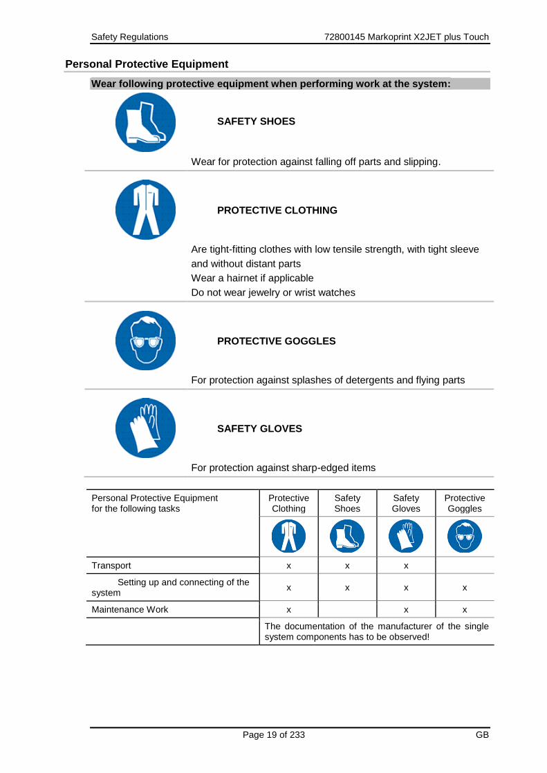
Wear following protective equipment when performing work at the system:
SAFETY SHOES
Wear for protection against falling off parts and slipping.
PROTECTIVE CLOTHING
Are tight-fitting clothes with low tensile strength, with tight sleeve
and without distant parts
Wear a hairnet if applicable
Do not wear jewelry or wrist watches
PROTECTIVE GOGGLES
For protection against splashes of detergents and flying parts
SAFETY GLOVES
For protection against sharp-edged items
Personal Protective Equipment for the following tasks
Protective Clothing
Safety Shoes
Safety Gloves
Protective Goggles
Transport x x x
Setting up and connecting of the system
x x x x
Maintenance Work x x x
The documentation of the manufacturer of the single system components has to be observed!

Safety Regulations 72800145 Markoprint X2JET plus Touch
Page 20 of 233 GB
Working Places Operator Personnel
The print system is an automatic working system and does not require any operation for the printing procedure.

Technical Specifications 72800145 Markoprint X2JET plus Touch
Page 21 of 233 GB
3. Technical Specifications
General
Dimensions (H x W x D in mm) 108 x 219 x 231 (excl. bracket and connections)
Weight 2850 g
Environmental Temperature:
5 - 40 ° C
Environmental Conditions: 10-90 % relative humidity (non-condensing)
Protection Rating IP 40
Maximum operating time The system is designed for continuous operating
Electrical
Voltage Power Supply: 90 - 240 V AC / 50-60Hz (1~)
Current consumption: max. 0,5 A
Power consumption: max. 60 W
Power consumption Standby:
< 5 W
Data interfaces
Ethernet RJ45
USB A USB-A socket
USB-B USB-B socket

Technical Specifications 72800145 Markoprint X2JET plus Touch
Page 22 of 233 GB
Connections
Input voltage 24V +- 10% max. 500mA
Sensor M8 4-pole
Encoder M8 4-pole
External Sub-D 25-pole
Alarm M12 8-pole
Supply voltage 24V +- 10% The switching threshold of the inputs is 12V ± 2V. The sensors / encoders must be designed for 24V operating voltage. E.g. 24V ±10% or 10V – 30V The inputs are NPN as standard, but can be rejumpered to PNP with the iDesign software.

Technical Specifications 72800145 Markoprint X2JET plus Touch
Page 23 of 233 GB
Performance data
Cable length in m
Power supply
Print head cable
Max. length print head cable:
Max. length LAN-cable:
2
3
Up to 13 for HP heads,
Up to 50 for LX or MX heads
Up to 50
Text layout Software iDesign
Parameter input Keyboard on the device / Software iDesign
Screen TFT display QVGA 5,7“ 320x240 pixel with background lighting
Fonts
(optional)
all available Windows fonts
customer-specific fonts
Print height in mm
HP / LX print heads:
MX print heads:
1 to 25
3 to 200
Maximum print resolution1) in dpi
HP / LX print heads:
MX print heads:
900
600
User language Control system / Software: German, English, French, further on request
Barcodes1) EAN 8, EAN 13, EAN 128, 2/5 ITF, 2/5 with check 128, UPC A, UPC E DUN14
2D-Codes1) Datamatrix, GS1-Datamatrix, OR-Code, PPN-Code
Automatic functions1) Date, Time, Counter, Variables, Action fields, customer-specific links
Graphic Monochrome bitmap-graphics can be created i.e. with Paint or other software.
Text memory in GB Max. 1
Font- und Logo memory in GB Max. 1

Technical Specifications 72800145 Markoprint X2JET plus Touch
Page 24 of 233 GB
Memory; optional expandable in GB 32
User memory in MB 64
Maximum print speed in m/min
(depending on resolution)
HP 2.5 at 300dpi
HP 2.5 at 300dpi HiSpeed Version
Recommended for barcodes
90
180
Max. 60
Maximum print speed in m/min
(depending on the resolution)
LX at 300dpi
LX at 300dpi HiSpeed Version
Recommended for barcodes
90
240
Max. 90
Maximum print speed in m/min
(depending on the resolution)
MX
200
Print direction L/R or R/L, from top or side. Print from bottom is not possible.
1) Not available in all Markoprint X2JET plus Touch versions

Technical Specifications 72800145 Markoprint X2JET plus Touch
Page 25 of 233 GB
Inks
HP-inks
Specification Type
Black HP-Set 4 STABL
HP-Set 14 MIBL 2
Cartridge HP Ultra Black
Cartridge HP 2580
Cartridge HP SDBLK3
Cartridge HP WDBLK1
Cartridge HP WDBLK2
Color HP-Set 26 RCBLU
HP-Set 27 RCRD
Cartridge HP WDGN1
Optional Special inks
HP-Set 12 UVINV
Other On request
LX-inks
Specification Type
Black LX GP+
LX GP1
LX SD1
LX RD1
LX NP1
Trident-inks
Specification Type
MX 100 ScanTrue II™ black,red
Versa™ V300 black, blue, green, red
MX 50 ScanTrue II™ black, red

Transport, Packaging and Storage 72800145 Markoprint X2JET plus Touch
Page 26 of 233 GB
4. Transport, Packaging and Storage
Transport
Check the delivery for completeness and transport damages immediately upon receipt. Proceed as follows in case of externally visible transport damage:
Decline delivery or accept with reservation only.
Record extent of damage in the transport documentation or on the delivery note of the carrier.
Initiate complaint. Scope of delivery
The scope of delivery of the Markoprint X2JET plus Touch depends on the ordered options and the customer’s application. Please control the scope of delivery when receiving the systems on the basis of the delivery note. Scope of Delivery - Basic:
1x Markoprint X2JET plus Touch control system
1x Power supply
1x CD, content: Chapter USB-Stick files, page 201
1x Operation manual (CD)
1x iDesign-Software (CD)
1x USB-cable A-B
1x Grounding cable Optional:
Print head: HP-print head, LX-print head or MX-print head
Print head cable
Mounting bracket
Photo sensor
Shaft encoder
Traffic light

Transport, Packaging and Storage 72800145 Markoprint X2JET plus Touch
Page 27 of 233 GB
Symbols on Packaging
As part of the installation and further use it may happen that the operator put user or maintenance personnel in charge of handling of packages. Therefore note the following important notes.
This way up
The arrowheads indicate the top of the package. They must always face upward to avoid damage to the content.
Fragile
Identifies packages with fragile or sensitive contents. Handle the package with care, do not drop or subject to impacts.
Keep dry
Keep packages away from moisture and keep dry.
Protect from heat
Protect packages from heat and direct sunlight.
Transport und Unpacking
Safety Instructions
Material damage due to incorrect transport!
Remove the packaging material and the transportation safety devices on installation site and transport the print system in its original packaging to the place of installation.
Danger due falling parts!
– Wear safety shoes!

Transport, Packaging and Storage 72800145 Markoprint X2JET plus Touch
Page 28 of 233 GB
Packaging
On Packaging
The individual packages are packed in accordance with the expected transport conditions. Only environmentally-friendly materials were used for packaging. Packaging serves to protect the individual components against transport damage, corrosion and other damage, up to the assembly stage. Do not, therefore, damage the packaging - remove shortly before assembly only. Original packaging is available from the manufacturer to ensure optimal dispatch of the system. Please contact your local distributor. Handling of packaging materials
Dispose of packaging material in accordance with the applicable statutory provisions and local regulations.
Environmental damage!
Packaging materials are valuable raw materials and can, in many cases, be re-used or profitably recycled and re-used.
Therefore:
– Dispose of packaging materials in an environmentally-responsible manner.
– Observe the locally applicable disposal regulations. If necessary, commission a specialized company for disposal.

Transport, Packaging and Storage 72800145 Markoprint X2JET plus Touch
Page 29 of 233 GB
Storage
Controller
Store the controller under the following conditions:
Do not store outdoors.
Keep dry and free of dust.
Do not expose to aggressive media.
Keep away from direct sunlight.
Avoid mechanical shock.
Storage temperature: 5°C to 45°C.
Relative humidity: maximum 60%. Storage HP print heads
Before storage of the HP print heads please remove the ink cartridges and store them like you can see under the point Storage notes of ink cartridges. Store the print heads under following conditions:
Do not store outdoors.
Keep dry and free of dust.
Do not expose to aggressive media.
Keep away from direct sunlight.
Avoid mechanical shock.
Storage temperature: 5°C to 45°C.
Relative humidity: maximum 60 %. Storage LX print heads
Before storage of the LX print heads please remove the ink cartridges and store them like you can see under the point Storage notes of ink cartridges. Store the print heads under following conditions:
Do not store outdoors.
Keep dry and free of dust.
Do not expose to aggressive media.
Keep away from direct sunlight.
Avoid mechanical shock.
Storage temperature: 5°C to 45°C.
Relative humidity: maximum 60 %.

Transport, Packaging and Storage 72800145 Markoprint X2JET plus Touch
Page 30 of 233 GB
Storage Trident print heads
Store the Trident print heads under following conditions: When a print head with ink type ScanTrue II is stored or not used for more than six months, ink deposits may form, which can result in the clogging of different nozzles. In this case, fill the print head with fresh ink before using. Procedure:
Leave the nozzle plate closed with the nozzle locking clamp!
Remove the feeder tube on the head and pump the old ink out of the ink supply system
Then remove the return flow from the ink system and pump the old ink out of the print head
Finally, rinse out the head and resume operation. Customers having replacement heads in storage should rotate them every three months. In this way, the customer has a regular control over the functional integrity of his print heads. All print heads must be tested once before installation. Before storage of the Trident print heads the ink bottle must be taken out and stored according the storage instructions given below ink bottles. The print head must be closed with the nozzle clip and the air inlet of the ink system must be closed with the plastic plug. Close the ink filler opening (bottle) with the screw cap. See also Disassembly of the print head. Store the print heads under following conditions:
Do not store outdoors.
Keep dry and free of dust.
Do not expose to aggressive media.
Keep away from direct sunlight.
Avoid mechanical shock.
Storage temperature: 5°C to 45°C.
Relative humidity: maximum 60 %.

Transport, Packaging and Storage 72800145 Markoprint X2JET plus Touch
Page 31 of 233 GB
Storage HP ink cartridge
New original sealed ink cartridges have a shelf life of up to 1 year. Observe the printed expiry date! The shelf life of different cartridge types differs. Storage < 2 days: Leave the ink cartridges in the print head holder and wipe off or rinse, if necessary, before restart. Chapter Cleaning the HP ink cartridge, page 177 Storage > 3 days: Please store the ink cartridge in a cartridge clip (CartClip). Chapter Store HP ink cartridge, page 31 Store HP ink cartridge
Material damage on the ink cartridges
The time, how long a cartridge can be stored without CartClip is different from the ink type. Especially solvent ink must be closed after use immediately.
Therefore:
– Insert the ink cartridges after use in a CartClip.
If ink cartridges are not used for an extended period of time, they must be stored in a cartridge clip (CartClip) to prevent the ink in the nozzles from drying out. To do this, the ink cartridges must be removed from the controller. Chapter Removing the HP ink cartridge, page 79
Instruction
To insert the ink cartridge in the CartClip:
Step Procedure
1 Close the CartClip over the ink cartridge and press until the top flap of the CartClip snaps into the holder. (see Fig. 4-1)
Fig. 4-1: Inserting the HP cartridge in a CartClip
Transport, Packaging and Storage 72800145 Markoprint X2JET plus Touch
Page 32 of 233 GB
Instruction
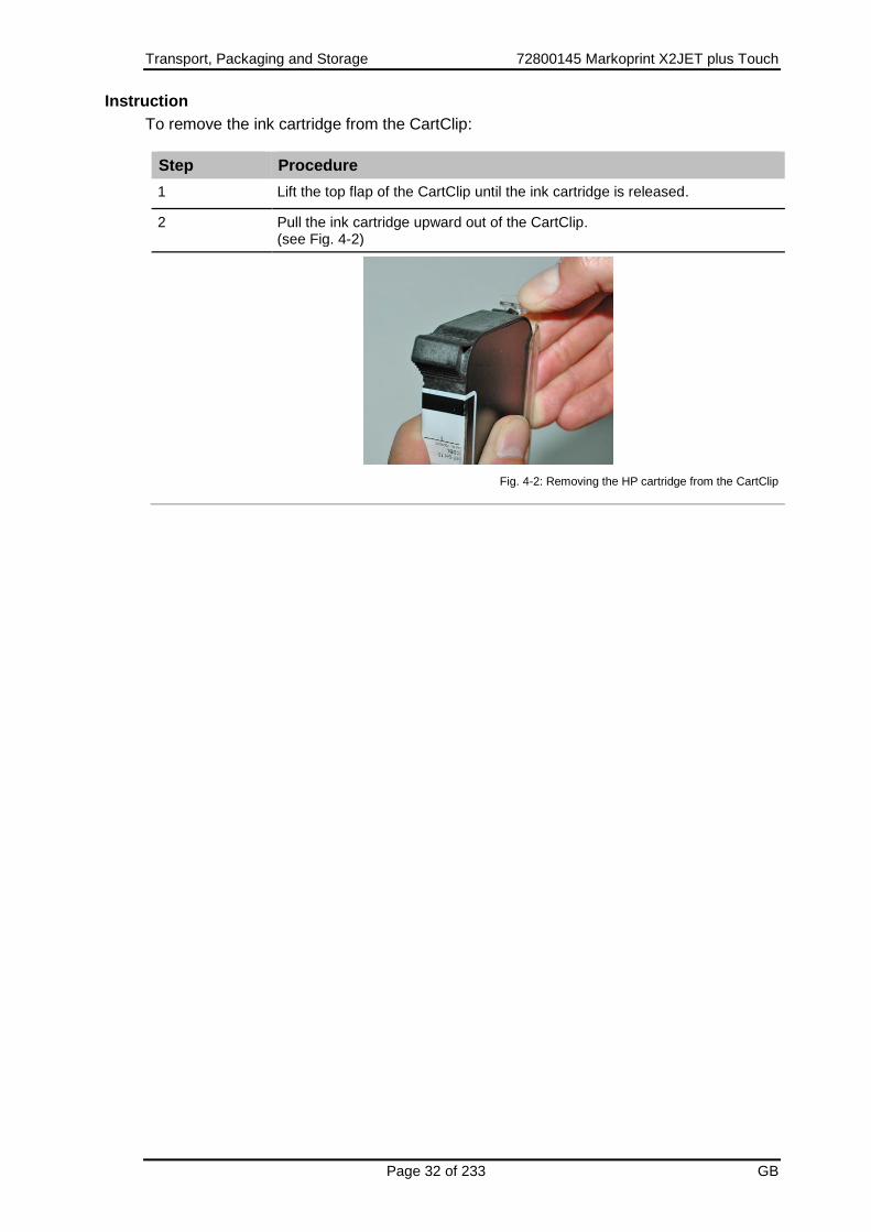
To remove the ink cartridge from the CartClip:
Step Procedure
1 Lift the top flap of the CartClip until the ink cartridge is released.
2 Pull the ink cartridge upward out of the CartClip. (see Fig. 4-2)
Fig. 4-2: Removing the HP cartridge from the CartClip

Transport, Packaging and Storage 72800145 Markoprint X2JET plus Touch
Page 33 of 233 GB
Storage LX ink cartridge
New original sealed ink cartridges have a shelf life of up to 1 year. Observe the printed expiry date! The shelf life of different cartridge types differs. Storage < 2 days: Leave the ink cartridges in the print head holder and wipe off or rinse, if necessary, before restart. Chapter Cleaning the HP ink cartridge, page 177 Storage > 3 days: If ink cartridges are not used for an extended period of time, they must be stored in a cartridge clip (CartClip). Chapter LX - Tintenkartusche aufbewahren, page 33 LX - Tintenkartusche aufbewahren
Material damage on the ink cartridges
The time, how long a cartridge can be stored without CartClip is different from the ink type. Especially solvent ink must be closed after use immediately.
Therefore:
– Insert the ink cartridges after use in a CartClip.
If ink cartridges are not used for an extended period of time, they must be stored in a cartridge clip (CartClip) to prevent the ink in the nozzles from drying out. To do this, the ink cartridges must be removed from the controller. Chapter Removing the HP ink cartridge, page 79 Instruction To insert the ink cartridge in the CartClip:
Step Procedure
1 Insert the ink cartridge in the CartClip. The nose of the CartClip to the back slightly until the cartridge click into place.
Fig. 4-3: Insert the LX cartridge in the CartClip

Transport, Packaging and Storage 72800145 Markoprint X2JET plus Touch
Page 34 of 233 GB
Instruction To remove the LX-ink cartridge from the CartClip:
Step Procedure
1 Pull the nose of the CartClip to the back slightly and remove the cartridge.
Fig. 4-4: Removing the HP cartridge from the CartClip

Transport, Packaging and Storage 72800145 Markoprint X2JET plus Touch
Page 35 of 233 GB
Storage Trident ink bottles
New original ink bottles can be stored up to one year. Please have a look at the printed best before date! The shelf life can be varying with the different ink types. Store the ink bottles under following conditions:
Do not store outdoors.
Keep dry and free of dust.
Do not expose to aggressive media.
Keep away from direct sunlight.
Avoid mechanical shock.
Storage temperature: 5°C to 45°C.
Relative humidity: maximum 60 %.

Construction and function 72800145 Markoprint X2JET plus Touch
Page 36 of 233 GB
5. Construction and function
Brief description
The Markoprint X2JET plus Touch is a thermal Inkjet Coder of Weber Marking Systems GmbH, for printing images quickly and cleanly onto smooth and absorbent product surfaces. A print image, for instance, contains product descriptions, graphics, quantities, shelf life data, barcodes and product serial numbers. Print layouts can be created with the included iDesign software and can send via network connection, USB interface or serial EIA 232 connection or by USB-stick to the Markoprint X2JET plus Touch.
Controller
The Markoprint X2JET plus Touch controller consists of:
The electronics inside the housing
A keyboard for input of parameter and settings and a navigation- / OK-button and the INFO-button.
Five menu selection-buttons for the direct selection of the shown display menu points
A color display
The connectors on the system back for power supply, input for encoder, input for sensor and other in-/outputs
The Markoprint X2JET plus Touch can be used as table system or can be installed on the production line directly with special optional mounting brackets or as wall-mounted system.

Construction and function 72800145 Markoprint X2JET plus Touch
Page 37 of 233 GB
System versions
The Markoprint X2JET plus Touch is available as standard version Advanced and as Pro-version with extended functions. Functions Markoprint X2JET plus Touch Advanced: Print speed up to 90m/min with HP at 300dpi, counter, date with best before, variable input, 2D barcodes, 1m print length (up to 2m at 300 dpi without zoom optimization), data backup with USB-Stick, interface functions, data base connection. Functions Markoprint X2JET plus Touch Pro: Like Markoprint X2JET plus Touch Advanced extra: Hi-Speed adjustable with print speed up to 240 m/min with LX at 300 dpi, up to 3m text length (up to 2m at 300 dpi without zoom optimization), password protection. The Markoprint X2JET plus Touch control systems will be delivered as Advanced version standard. If the requirements exceed the scope of services of the Advanced version, an upgrade with costs to the Pro version is available. See also Chapter Software-Upgrade, page 197.

Construction and function 72800145 Markoprint X2JET plus Touch
Page 38 of 233 GB
Overview Markoprint X2JET plus Touch controller
Fig. 5-1: X2JET plus controller
No. Description
1 STATUS LIGHTS
2 FUNCTION BUTTONS
3 INFO-BUTTON
4 NAVIGATION- / OK-BUTTON
5 KEYBOARD
6 DISPLAY / TOUCHSCREEN
1 2
3
4
5
6

Construction and function 72800145 Markoprint X2JET plus Touch
Page 39 of 233 GB
Overview print heads
Overview HP print heads
The print heads will be installed with mounting brackets at the production line directly. The HP print heads consist of:
Cartridge bracket
Ink cartridge
Controller connector
Integrated electronics
Fig. 5-2: Print head HP MK2 Version 1 Single model
No. Description
1 DEFLECTOR
2 INK CARTRIDGE
3 STATUS LED
4 CONTROLLER CONNECTION
5 OPENING EXTERNAL SENSOR
The HP print heads are available in three different versions:
HP MK2 Version 1 – flat version (196,5mm) with connector at the back
HP MK2 Version 2 – short version (187mm) with connector at the bottom Detailed dimensional drawing see appendix.
2
1
4
4
3

Construction and function 72800145 Markoprint X2JET plus Touch
Page 40 of 233 GB
Fig. 5-3: Print head HP MK2 Version 1
Fig. 5-4: Print head HP MK2 Version 1

Construction and function 72800145 Markoprint X2JET plus Touch
Page 41 of 233 GB
The HP print head works with original Hewlett-Packard ink cartridges. The HP print heads are available as single model or as cascaded version up to two print heads. A single print head has a maximum print height of 12.5 mm and increase 12.5 mm with each further print head as cascaded version (two print heads = 25 mm).. Functional principle: The ink is located in the ink channels of the printer cartridge, while its viscosity prevents any leakage. A heating element, which generates a steam bubble when current is briefly applied (1.9 µs), is fitted behind each jet opening. This steam bubble gives ink between the heating element and the jet opening an impulse and therefore “shoots” a defined quantity of ink out of the opening. When the steam bubble reforms, a corresponding quantity is drawn from the storage container and the process can begin again. This process of ejecting an ink drop can be repeated 18,000 times a second. There are different special inks, which allow a coding on many surfaces. Specially qualified are inks for absorbent and semi absorbent surfaces. For non-absorbent surfaces are solvent inks available. The drying time can be realized with a blower or heater.

Construction and function 72800145 Markoprint X2JET plus Touch
Page 42 of 233 GB
SmartCard Functionality
The Markoprint X2JET plus / plus Touch print system is equipped in the MK2 version with
SmartCard identification of the cartrigdes.
The HP MK2 printhead has an additional contact block which connects the SmartCard chip with
the analysis electronics by insertion of the SmartCard cartridge.
View of the SmartCard contacting View of the SmartCard cartridge
The chip is detected by inserting the cartridge. The printhead LED show this:
The head LED blinks green for 3 seconds if the SmartCard is detected.
The LED blinks green/red if a cartridge without SmartCard is inserted. The system works without the advantages of the SmartCard data.
If the print system isn’t activating for the use of cartridges without SmartCard, the LED will be blink red and the print system doesn’t print.
The LED blinks yellow/red if there is a read error on the SmartCard chip and the cartridge prints without consideration of the SmartCard data.

Construction and function 72800145 Markoprint X2JET plus Touch
Page 43 of 233 GB
SmartCard Functions
The SmartCard functions are supported by software version 2.016 and higher.
Automatic storage of the ink filling level in 1% steps. The correct ink level of a cartridge is always
detected, even by changing the cartridges. No more missing prints by interchanged cartridges.
Automatic detection of the ink type and automatic setting of the optimal ink paramaters. Ink
volume, drop size, nozzle voltage and firing time are stored on the SmartCard chip.
The current ink type is displayed for control and prevention of wrong cartridges.
Exact ink consumption calculation. The usable number of drops is calculated by the ink weight
(g), specific weight (g/ml) and drop size (in pl). The values are read out of the chip, depending on
the ink type.
Warning message with expired shelf life - date of filling and shelf life are stored on the SmartCard
chip
Warning message if cartridge is open for too long (installed life) - date of first insertion and
maximum operating time are stored on the SmartCard chip.
iDesign displays the ink part number for easy reordering.
Following data are stored on the SmartCard chip for checking claims:
Date of the first cartrigde insertion, serial number of the controller, firmware version of the
controller
Date of the last cartridge insertion, serial number of the controller, firmware version of the
controller
Number how many times the cartridge was used.
The ink type can not set manually by using SmartCard cartridges.
The ink level is set automatically and can not be reset.

Construction and function 72800145 Markoprint X2JET plus Touch
Page 44 of 233 GB
Overview LX print heads
The print heads will be installed with mounting brackets at the production line directly. The LX print heads consist of:
Cartridge bracket
Ink cartridge
Controller connector
Integrated electronics
Fig. 5-5: Print head LX MK2 Version 1 Single model
No. Description
1 INK CARTRIDGE
2 DEFLECTOR
3 OPENING EXTERNAL SENSOR
4 STATUS-LED
5 CONTROLLER CONNECTOR
6 CLAMP LEVER CARTRIDGE
2
1
3
5
4
6

Construction and function 72800145 Markoprint X2JET plus Touch
Page 45 of 233 GB
The LX print heads are available in two different versions:
LX MK2 Version 1 – flat version, with connector at the back
LX MK2 Version 2 – version with connector at the bottom Detailed dimensional drawing see appendix.
Fig. 5-6: Print head LX MK2 Version 1
Fig. 5-7: Print head LX MK2 Version 1

Construction and function 72800145 Markoprint X2JET plus Touch
Page 46 of 233 GB
The LX print head works with original Lexmark ink cartridges. The LX print heads are available as single model or as cascaded version up to two print heads. A single print head has a maximum print height of 12.5 mm and increase 12.5 mm with each further print head as cascaded version (four print heads = 25 mm). Functional principle: The ink is located in the ink channels of the printer cartridge, while its viscosity prevents any leakage. A heating element, which generates a steam bubble when current is briefly applied, is fitted behind each jet opening. This steam bubble gives ink between the heating element and the jet opening an impulse and therefore “shoots” a defined quantity of ink out of the opening. When the steam bubble reforms, a corresponding quantity is drawn from the storage container and the process can begin again. This process of ejecting an ink drop can be repeated 12,000 times a second. There are different special inks, which allow a coding on man surfaces. Specially qualified are inks for absorbent and semi absorbent surfaces. For non-absorbent surfaces are solvent inks available. The drying time can be realized with a blower or heater. The system is optimized for Weber cartridges. The ink settings (Fire pulse, spitting, warming) will set optimal by using Weber cartridges. These values cannot determine and set by using other cartridges. Then the ink level is 1% (warning level).
Construction and function 72800145 Markoprint X2JET plus Touch
Page 47 of 233 GB
MX print heads
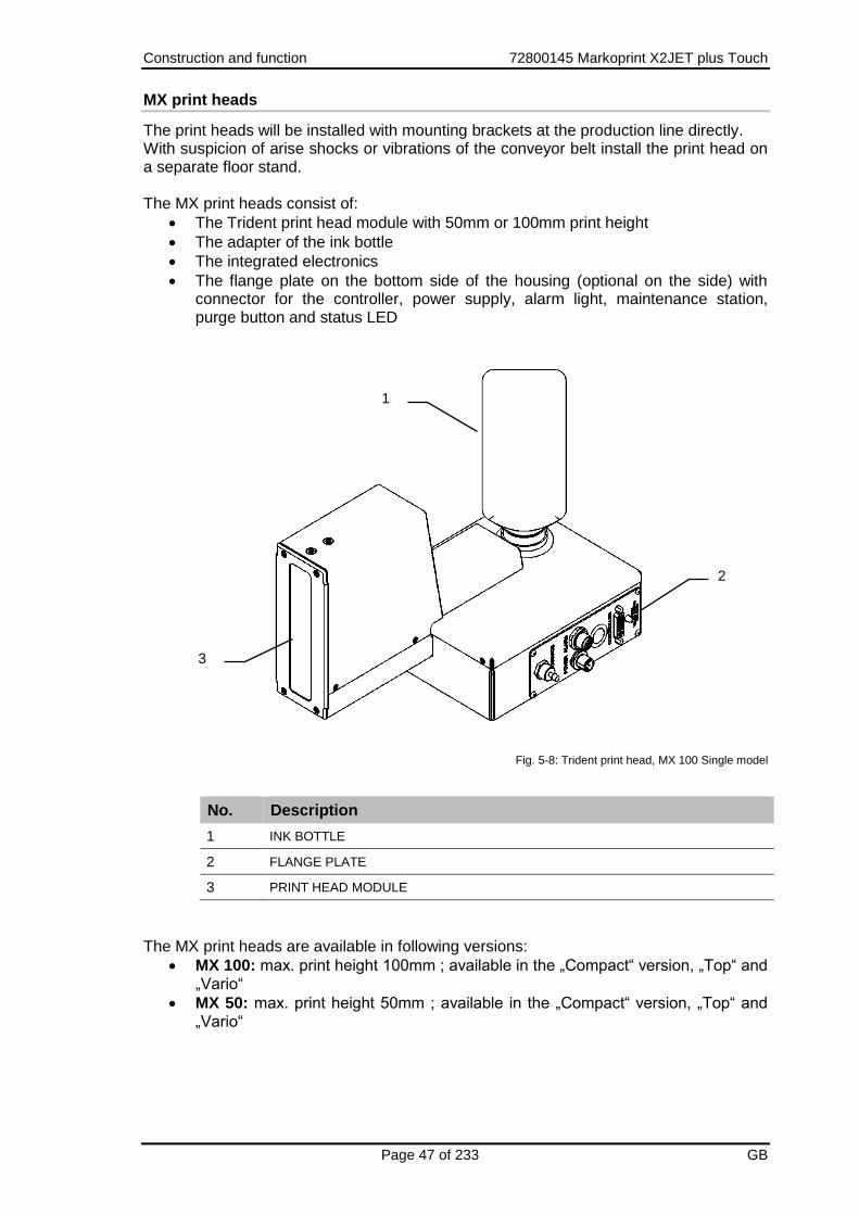
The print heads will be installed with mounting brackets at the production line directly. With suspicion of arise shocks or vibrations of the conveyor belt install the print head on a separate floor stand. The MX print heads consist of:
The Trident print head module with 50mm or 100mm print height
The adapter of the ink bottle
The integrated electronics
The flange plate on the bottom side of the housing (optional on the side) with connector for the controller, power supply, alarm light, maintenance station, purge button and status LED
Fig. 5-8: Trident print head, MX 100 Single model
No. Description
1 INK BOTTLE
2 FLANGE PLATE
3 PRINT HEAD MODULE
The MX print heads are available in following versions:
MX 100: max. print height 100mm ; available in the „Compact“ version, „Top“ and „Vario“
MX 50: max. print height 50mm ; available in the „Compact“ version, „Top“ and „Vario“
2
1
3

Construction and function 72800145 Markoprint X2JET plus Touch
Page 48 of 233 GB
Fig. 5-9: Trident print head, MX 50 Compact model
Fig. 5-10: Trident print head, MX 50 Top model
Fig. 5-11: Trident print head, MX 50 Vario model
Print head distance: The distance from nozzle to nozzle is 150 mm if two or more print heads will be installed to print 150 mm or higher. The distance can be set from 50 to 200 in iDesign. The 50mm print head (if needed) must the top print head.

Construction and function 72800145 Markoprint X2JET plus Touch
Page 49 of 233 GB
150mm
Fig. 5-12: MX print heads, type 100 and 50

Construction and function 72800145 Markoprint X2JET plus Touch
Page 50 of 233 GB
Trident – print head module MX 100 / 50
Material damage
The nozzle plate can be damaged by incorrect disassembly.
Therefore:
Never remove the nozzle plate - this would invalidate the warranty.
The print head MX 100 has 256 selectable channels, each with 3 nozzle openings. The print head MX 50 has 128 selectable channels, each with 3 nozzle openings. The nozzle plate is permanently screwed to the metal body.
Fig. 5-13: Trident print head module MX 100
No. Description
1 INK RETURN
2 NOZZLE PLATE
3 NOZZLE OPENINGS
4 MAINTENANCE STATION CONNECTOR
5 INK SUPPLY
The Trident print heads are available as single version. Up to two print heads can be cascaded. The single print head as 50 version has a maximum print height of 50 mm, the 100 version a print height of 100 mm. The print height will be higher with a cascading of every additional print head (two 100er print heads = 200 mm). The 50er and 100er print heads can be mixed together.
1
4
5
2
3
Construction and function 72800145 Markoprint X2JET plus Touch
Page 51 of 233 GB
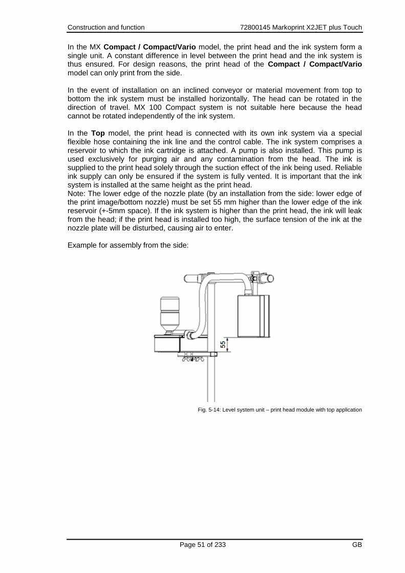
In the MX Compact / Compact/Vario model, the print head and the ink system form a single unit. A constant difference in level between the print head and the ink system is thus ensured. For design reasons, the print head of the Compact / Compact/Vario model can only print from the side. In the event of installation on an inclined conveyor or material movement from top to bottom the ink system must be installed horizontally. The head can be rotated in the direction of travel. MX 100 Compact system is not suitable here because the head cannot be rotated independently of the ink system. In the Top model, the print head is connected with its own ink system via a special flexible hose containing the ink line and the control cable. The ink system comprises a reservoir to which the ink cartridge is attached. A pump is also installed. This pump is used exclusively for purging air and any contamination from the head. The ink is supplied to the print head solely through the suction effect of the ink being used. Reliable ink supply can only be ensured if the system is fully vented. It is important that the ink system is installed at the same height as the print head. Note: The lower edge of the nozzle plate (by an installation from the side: lower edge of the print image/bottom nozzle) must be set 55 mm higher than the lower edge of the ink reservoir (+-5mm space). If the ink system is higher than the print head, the ink will leak from the head; if the print head is installed too high, the surface tension of the ink at the nozzle plate will be disturbed, causing air to enter. Example for assembly from the side:
Fig. 5-14: Level system unit – print head module with top application

Construction and function 72800145 Markoprint X2JET plus Touch
Page 52 of 233 GB
Fig. 5-15: Level system unit – print head module with top system and printing from side
Functional principle: The ink is distributed in the ink channels through capillary action. In order to optimize the viscosity of the ink, the head is heated to approximately 35°C (with ScanTrue II ink). Or 65°C (with Versa ink). This takes about 5 minutes from the time the device is switched on. Each ink channel contains a piezo tappet that contracts when an electrical pulse is applied. At the end of the pulse, the tappet expands suddenly and pushes the ink against the nozzle plate. The nozzle plate forms the ink into individual drops that are ejected onto the printing surface. When the drops exit the print head, a suction pressure is generated that pulls more ink from the tube. The surface tension of the ink present directly at the nozzles prevents ingress of air into the ink channels. Please note that the print head must be protected from strong vibrations. Strong impacts may lead to disruption of the surface tension and ingress of air into the head. Only those inks listed on the gummed label of the unit may be used in the system. The use of other inks will cause a total breakdown of the printer system! The system must not be run dry / without ink. The system is supplied filled with ink. Ink could escape if the device is not closed and not stored properly. If ink has escaped, air must be removed from the system before using. The ink tank has a ventilation cap that must remain open at all times after installation!
Construction and function 72800145 Markoprint X2JET plus Touch
Page 53 of 233 GB
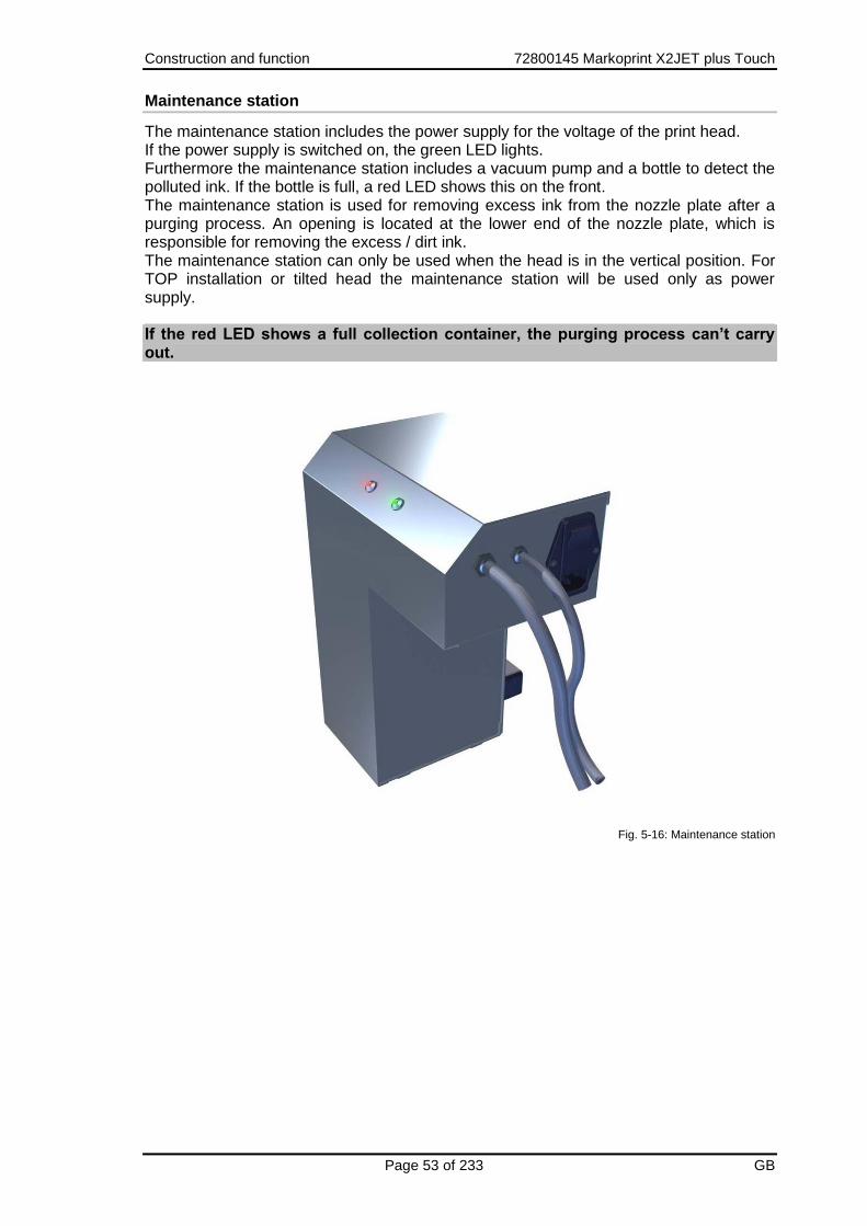
Maintenance station
The maintenance station includes the power supply for the voltage of the print head. If the power supply is switched on, the green LED lights. Furthermore the maintenance station includes a vacuum pump and a bottle to detect the polluted ink. If the bottle is full, a red LED shows this on the front. The maintenance station is used for removing excess ink from the nozzle plate after a purging process. An opening is located at the lower end of the nozzle plate, which is responsible for removing the excess / dirt ink. The maintenance station can only be used when the head is in the vertical position. For TOP installation or tilted head the maintenance station will be used only as power supply. If the red LED shows a full collection container, the purging process can’t carry out.
Fig. 5-16: Maintenance station
Construction and function 72800145 Markoprint X2JET plus Touch
Page 54 of 233 GB
Nameplates
Nameplate controller
The nameplate is attached to the bottom of the device and displays the following:
System type
Serial number
MAC address
Article number
Supply voltage
Power consumption
Address of manufacturer Nameplate print head
The nameplate is attached to the side of the print head and displays the following:
System type
Serial number
Supply voltage
Power consumption
Address of manufacturer

Installation and Initial Operation 72800145 Markoprint X2JET plus Touch
Page 55 of 233 GB
6. Installation and Initial Operation Safety notes
Danger to life through electric shock!
DANGER TO LIFE!
Contact with live parts poses imminent danger to life. Damaged insulation or individual components can be lethal.
Therefore:
– Immediately switch off the power supply and initiate repairs if the insulation is damaged.
– Work on the electrical system may only be performed by electricians.
– Before working on the electrical system, disconnect from the mains (remove mains plug) and check that power is off.
– Always disconnect mains before performing cleaning and repair tasks.
– Keep moisture from live parts. Moisture may cause a short-circuit.
Risk of stumbling posed by dirt, objects lying about and connecting lines!
RISK OF INJURY!
Dirt, objects lying about and connecting lines for power, data- and signal lines may cause slipping and stumbling resulting in severe injuries.
Therefore:
– Always keep working area clean.
– Remove objects no longer required.
– Mark stumbling areas with yellow-black marking tape.
– Non tension connecting lines to system and pass it that no places of danger do arise.

Installation and Initial Operation 72800145 Markoprint X2JET plus Touch
Page 56 of 233 GB
Edges and corners pose risk of injury!
RISK OF INJURY!
Sharp edges and pointed corners may cause abrasions and cuts to the skin.
Therefore:
– Be cautious when working near sharp edges and pointed corners.
– If in doubt, wear protective gloves.

Installation and Initial Operation 72800145 Markoprint X2JET plus Touch
Page 57 of 233 GB
Installation
Only an optimally aligned installation of the system can ensure a continuous operation with a low rate of failures and a minimum wear. For an optimized installation of the system, fine tunings adapted to environmental conditions are essential. For the fine tunings, a complex expert knowledge is required basing on experience with print technique. The complexity of a wear-optimized installation requires a high measure of specialized knowledge and experience, which cannot be obtained completely by reading this manual. Therefore the installation of the print system must be made by a technician from your local distributor or examined by a final inspection. Damage or damages based on an incorrect installation, represent no case of warranty. Requirements to the Site of Installation
When choosing the installation location the following conditions apply:
Consider the generally accepted ergonomic criteria in accordance with workplace ordinances as well as country-specific legislation.
The installation location must be a dry and dust-free room, ideally with an ambient temperature of approx. 18…25 °C.
The installation location may not be subject to fast temperature fluctuations (condensation!).
Do not set up the controller directly next to or above hot surfaces, since this will affect cooling of the controller.
If the controller is operated on a tripod (accessory), the stability of the tripod on an even foundation must be ensured.
The controller may not be exposed to flammable, explosive, corrosive gases or chemical vapors.
The controller may not be installed in the vicinity of high voltage equipment or power supplies.
The controller may not be subjected to direct vibrations or shocks.
Keep controller away from oil or water.
The controller may not be exposed to strong magnetic or electric fields. Placing the Control System
The installation position has to provide sufficient access for user and service technician. The power plugs must be easy to access to cut the voltage anytime.
Observe that all mounting parts are fixed sufficiently.
Consider all points of the "Intended Use" in the chapter safety regulations. To achieve a clean, sharp print result the distance from the product to be printed to the cartridge nozzle plate is important. The optimum distance is 0 to 4 mm between the deflector and the product. A greater distance will adversely affect the print result, particularly at high conveyor belt speeds. The higher the print speed the shorter must be the distance. At speeds of less than 20 m/min a distance of up to 4 mm between the nozzle plate and the product may still be acceptable.

Installation and Initial Operation 72800145 Markoprint X2JET plus Touch
Page 58 of 233 GB
Positioning the Control System
Material damage due to improper print system installation!
With the print system switched on, a defect may occur in the system electronics.
Therefore:
– Only install the system when it is switched off.
– Network cables only connect or disconnect if the power supply is dead voltage.
Material damage due to induced currents!
If the connection cables of the controller run close to high voltage or heavy current cables in the cable duct, induction may cause malfunctioning or damage.
Therefore:
– Lay all connection cables of the controller spatially separate from high voltage and heavy current cables.
Material damage due to an incorrect control system installation!
Faults on the control system can happen by potential differences between control system and conveyor belt.
Therefore:
– An electro-conductive connection between control system and conveyor belt must be established.
Material damage due to not properly installed connecting cables!
Improper installation of the connecting cables can cause damages to these.
Therefore:
– When laying the cables, ensure that cables are not tripping hazards and do not lay them around corners and sharp edges. Avoid abrasive surfaces.

Installation and Initial Operation 72800145 Markoprint X2JET plus Touch
Page 59 of 233 GB
Required Resources Setscrew wrench (Allen key®) SW5 Instruction Please install the control system as follows:
Step Procedure
1 Set up the controller …
on an even and adequately load-bearing surface
mount on a tripod
Install it on a production line with the optional available mounting brackets.
Install it on a wall with the optional available mounting brackets.
2 Connect the control system with the conveyor belt electro-conductive.
Installation of the print heads
Installation of the HP print head
To achieve a clean and sharp printing result, the distance between the product to be printed and the nozzle plate of the print head is important. The optimal distance is 0 to 4 mm. A higher distance impairs the print result, especially if the conveyor belt runs at high speeds. The distance from the print head to the product must be as short as possible, with high print speed mainly. The distance between print head and product can be 5 mm if the print speed is less than 20 m/min. Required Resources
Setscrew wrench (Allen key®) SW5
Crosstip screwdriver Instruction Please install the HP print head as follows:
Step Procedure
1 Attach mounting brackets to the production line.
2 Attach the mounting rail of the print head to the clamp of the mounting bracket.
3 Set the distance between the print head and the product surface. A distance of 0 to 4 mm is optimal.

Installation and Initial Operation 72800145 Markoprint X2JET plus Touch
Page 60 of 233 GB
Step Procedure
Fig. 6-1: HP print head installation at the production line
4 Connect the print head cable to the connector of the print head and screw tight.
5 Connect the light barrier cable to the connector of the photo sensor and tighten.
6 Using the two screws supplied, mount the light barrier to the print head in such a way that the product to be printed passes the light barrier before passing the print head. The photo cell should have an unlimited view to the product (send- and reception diode). Tighten the screws only to the extent that the plastic enclosure will not be damaged. Alternatively, another sensor may be used. Observe the direction of movement of the conveyor belt!
7 Mount optional rotary encoder on production line.
8 Connect the rotary encoder cable to the rotary encoder connector and fasten.
9 Remove the protective foil from the nozzle plate and insert the ink cartridge in the holder Chapter Inserting the HP ink cartridge, page 77
0 – 4mm

Installation and Initial Operation 72800145 Markoprint X2JET plus Touch
Page 61 of 233 GB
Installation of the LX print head
To achieve a clean and sharp printing result, the distance between the product to be printed and the nozzle plate of the print head is important. The optimal distance is 0 to 8 mm. A higher distance impairs the print result, especially if the conveyor belt runs at high speeds. The distance from the print head to the product must be as short as possible, with high print speed mainly. The distance between print head and product can be 8 mm if the print speed is less than 20 m/min. Required Resources
Setscrew wrench (Allen key®) SW5
Crosstip screwdriver Instruction Please install the LX print head as follows:
Step Procedure
1 Attach mounting brackets to the production line.
2 Attach the mounting rail of the print head to the clamp of the mounting bracket.
3 Set the distance between the print head and the product surface. A distance of 0 to 8 mm is optimal.
Fig. 6-2: LX print head installation at the production line
4 Connect the print head cable to the connector of the print head and screw tight.
5 Connect the light barrier cable to the connector of the photo sensor and tighten.
6 Using the two screws supplied, mount the light barrier to the print head in such a way that the product to be printed passes the light barrier before passing the print head. The photo cell should have an unlimited view to the product (send- and reception diode). Tighten the screws only to the extent that the plastic enclosure will not be damaged. Alternatively, another sensor may be used. Observe the direction of movement of the conveyor belt!
0 – 8mm

Installation and Initial Operation 72800145 Markoprint X2JET plus Touch
Page 62 of 233 GB
Step Procedure
Fig. 6-3: Installation of the product sensor at the LX print head
7 Mount optional rotary encoder on production line.
8 Connect the rotary encoder cable to the rotary encoder connector and fasten.
9 Remove the protective foil from the nozzle plate and insert the ink cartridge in the holder Chapter Inserting the HP ink cartridge, page 77
Direction
Photo sensor

Installation and Initial Operation 72800145 Markoprint X2JET plus Touch
Page 63 of 233 GB
Installation of the MX print head
Possible material damages!
Prepared product-side guidance protects the control system against vibrations and damages while the product passes the control system.
The distance from the product, which should be print, to the nozzle plate of the print head is important to get a clean and sharp print image. The optimal distance is 1 to 4 mm between deflector and product. An upper distance corrupts the print result, especially with high print speed. The higher print speed, the smaller must be the distance. With a print speed lower than 20 m/min, a distance of 5 mm between nozzle plate and product can be acceptable. Required Resources
Setscrew wrench (Allen key®) SW5 Instruction Please install the MX print head as follows:
Step Procedure
1 Install print head, ink system and maintenance station / power supply! The system must build up stable before opening the ink system and nozzle plate!
2 Set level (only Top version systems!). It is important to install the ink system at the same height as the print head. There is necessary: Set a height of 55mm (± 5mm) from the lower edge of the ink system housing to the lowermost write channel of the nozzle plate. If the ink system is higher than the print head, ink runs out at the head. If the print head is installed too high, the surface tension of the ink at the nozzle plate breaks and air enters.
3 Switch system on Wait till operating temperature is reach.
4 Open ink system! Remove the plastic ink system cover. The ink system reservoir features a vent cap that has to be opened prior to commissioning. This cap then remains permanently open and is only closed again if the print head and ink system must be dismantled and, for example, relocated.
Fig. 6-4: Venting Trident ink tank
5 Remove the protective cap, wipe the ink away and place it in the ink system.

Installation and Initial Operation 72800145 Markoprint X2JET plus Touch
Page 64 of 233 GB
Step Procedure
Check whether the red sealing ring (o-ring) is present. Place the red sealing ring into the opening of the ink container and insert the ink cartridge.
6 Open print head! The front panel is protected during transport by means of a spring steel cap with a silicone rubber strip inlay. The vent opening at the ink system reservoir is closed. This prevents ink from leaking and air from entering during transport. Remove the protective cap from the nozzle plate once you have opened the vent cap in the ink system.
7 Test print! A test print can be run after standby is displayed. Rinse the head if some lines are missing Chapter Rinsing and bleeding the MX print head, page 181
Compact mounting bracket
The MX Compact mounting bracket is used to install the print head in the Compact
model. The print head and ink system are consolidated into a single unit.
Fig. 6-5: Compact mounting bracket
The service unit is mounted on the lower leg of the mounting bracket. Optionally, it can be mounted directly at the transport belt or on a separate floor support. Ensure that the service unit is lower than the print head so that no ink can run back to the head.

Installation and Initial Operation 72800145 Markoprint X2JET plus Touch
Page 65 of 233 GB
Top – mounting bracket
Possible material damages!
Faults on the control system can happen by potential differences between control system and conveyor belt. An electro-conductive connection between control system and conveyor belt must be established.
In preparation Note the following if the MX Top mounting bracket cannot be used and you have to use your own bracket:
– The level between the print head and the ink system has to be set accurately at all times.
Any height adjustments of the print head must always be carried out together with the ink
system.
– The lower edge of the nozzle plate 55 mm should be set (+-5mm) higher as the upper
edge of the reservoir in the ink system.
– If the ink system is higher than the print head, the ink will leak from the head; if the print
head is installed too high, the surface tension of the ink at the nozzle plate will be
disturbed, causing air to enter.
Please note: (General)
– As explained in the functional description, the print head should not be subjected to
impacts or vibrations. To ensure faultless operation, the print head should therefore be
protected against:
– Impact and vibrations near the point of installation. It may be preferable to install the print
head and the ink system on a MX floor support (see appendix) on the floor of the hall.
– The product itself! Lateral guides must reliably prevent the material to be printed (e.g. the
front edge of a cartons) to come into contact with the print head, which could result in
impacts (causing air bubbles in the system) or even damage to the nozzle plate.

Installation and Initial Operation 72800145 Markoprint X2JET plus Touch
Page 66 of 233 GB
Connecting the control system
The Print system needs electricity for its functions. Please find more details in the chapter “Technical Data“. Overview of the control system connections
Fig. 6-6: X2JETplus control system back- / connection side
No. Description
1 USB-A
2 USB-B
3 NETWORK CONNECTION
4 OPTIONAL IN-/OUTPUTS
5 POWER CONNECTION
6 ALARM - M12
7 ENCODER - M8
8 SENSOR - M8
9 PRINT HEAD CONNECTIONS
1 2
3 4
6 7
8
9
5

Installation and Initial Operation 72800145 Markoprint X2JET plus Touch
Page 67 of 233 GB
Connecting to Supply Voltage
Requirements
Power supply according to "Technical Data" is installed close (max. 1,5 m away)
to the control system. Instruction Please connect the control system with supply voltage as follows:
Step Procedure
1 Compare the mains data with the technical data of the control system. Chapter Technical Specifications, page 21 Elektrischen Anschluss nur bei Übereinstimmung vornehmen!
2 Connect the power plug to the power socket on the control system.
Fig. 6-7: Power socket control system
3 Connect the power plug with an isolated ground receptacle.

Installation and Initial Operation 72800145 Markoprint X2JET plus Touch
Page 68 of 233 GB
Connecting of the Print heads
Requirements
The print head is mounted on a production line. Instruction Please connect the print head with the control system as follows:
Step Procedure
1 Connect the print head cable of the first head (top head in a cascaded installation) to the HEAD 1 socket and tighten.
Fig. 6-8: Print head connection socket at the back of the control system
2 Connect the print head cable of the second head to the HEAD 2 socket and tighten.
Fig. 6-9: Print head connection socket at the back of the control system
Connecting the optional Shaft Encoder
Requirements
The optional shaft encoder is mounted at the production line.
Ideally runs the measuring wheel of the shaft encoder on the conveyor belt, near the print system.
The encoder is activated in the system menu. Instruction Please connect the optional shaft encoder with the control system as follows:
Step Procedure
1 If necessary install the optional shaft encoder on the production line and connect it to the Encoder socket.
Fig. 6-10: Encoder socket (M8 4-pole) at the back side of the control system

Installation and Initial Operation 72800145 Markoprint X2JET plus Touch
Page 69 of 233 GB
Connecting the optional Product Sensor
Requirements
The optional shaft encoder is mounted at the production line.
Between the sensor and the nozzle plate is maximum a product, because another print activation is otherwise ignored.
Instruction Please connect the optional product sensor with the control system as follows:
Step Procedure
1 If necessary install the optional shaft encoder on the production line and connect it to the Sensor socket.
Fig. 6-11: Sensor socket (M8 4-pole) at the back side of the control system
Connecting the optional Alarm Light
Requirements
The optional alarm light is mounted at the production line. Instruction Please connect the optional alarm light with the control system as follows:
Step Procedure
1 If an alarm light (accessory) is installed, connect the alarm light cable to the Alarm socket and tighten.
Fig. 6-12: Alarm socket (M12) at the back side of the control system

Installation and Initial Operation 72800145 Markoprint X2JET plus Touch
Page 70 of 233 GB
Connection for optional Inputs / Outputs
Requirements The cabling of the socket is connected according the requirements.
Instruction Please connect the optional inputs with the control system as follows:
Step Procedure
1 Connect and tighten the input cable to the Extern socket, if external inputs are installed.
Fig. 6-13: Extern socket (Sub-D 25-pole) at the back side of the control system
Connection to a network
A RJ-45-connection allows a connection of the print system to the customer LAN (Local Aera Network). The LED on the top of the system lights green if a network is available. The LED flashes yellow with data communication. Instruction Please connect the control system with the network as follows:
Step Procedure
1 If required connect the print system to the network by a RJ45 socket.
Fig. 6-14: Ethernet socket (RJ 45) at the back of the control system
Each IP address can place in a network once only. Otherwise there is an address conflict and the system can’t address. Please contact your system administrator.

Installation and Initial Operation 72800145 Markoprint X2JET plus Touch
Page 71 of 233 GB
Connection of the print heads
Overview of the connectors on the MX print head
Material damages due to rest of ink!
It remains a rest of ink at the connectors all times, which can cause pollutions.
Therefore:
– Wipe the ink connectors always clean.
Fig. 6-15: MX connectors
No. Description
1 CONNECTOR FOR SUCK-UP THE MAINTENANCE STATION
2 CONNECTOR FOR AN OPTIONAL WARNING SIGNAL (ALARM LIGHT)
3 PURGE BUTTON
4 PRINT HEAD CONNECTOR
5 STATUS-LED
6 CONNECTOR POWER SUPLLY MAINTENANCE STATION / MAIN ADAPTER
Status-LED Description
GREEN: OK OK
YELLOW:Warning Empty ink cartridge, head isn’t heated up.
RED: Failure Ink tank is empty completely, head heating.
BLUE flashing: Data transfer
1
6
2
3
4
5

Installation and Initial Operation 72800145 Markoprint X2JET plus Touch
Page 72 of 233 GB
Name Description
MAINTANANCE Snap closure connector for a connection of the maintenance station suck-up. If the connection is interrupted, both snap closures will be closed, so that no ink can run out.
POWER Connector for the power supply (24V DC / 25W) with 4pin M12 connector. Pin1: + 24V Pin2: Rest tank full Pin3: 0V (GND) Pin4: Vacuum pump
ALARM Alarm light connector with 8 pin M12 connector
PURGE With a short push on the button it happen a flush run: The vacuum pump runs 3 seconds, after it the slush pump runs 0,3 seconds and the vacuum pump another 10 seconds. With a long push the pump runs permanent.
The vacuum pump runs for 10 seconds all 2 minutes to suck off the rests from the nozzle plate. When the Compact system is switched on, the flush run happens one time to clean up the nozzle plate. This doesn’t happen by the Top version. If the button will be pressed more than 20 seconds, the slush pump runs continuously until the button will be lose. This is only necessary by service for venting.

Installation and Initial Operation 72800145 Markoprint X2JET plus Touch
Page 73 of 233 GB
Inserting the Trident ink bottle
Material damages due to misuse!
A over fitting of the ink bottle can damage the Trident ink reservoir.
Therefore:
– Tighten the ink cartridge only lightly (like you would a light bulb, for example).
Use the ink bottle as soon as possible after having removed the protective foil. Instruction Please insert the Trident ink bottle in the print head as follows:
Step Procedure
1 Unscrew the large protecting cover of the ink system, wipe it clean and store it inside the ink system housing.
2 Then remove the protective foil from the screw thread of the ink cartridge.
3 Screw the cartridge into the reservoir opening. Avoid tilting the thread.
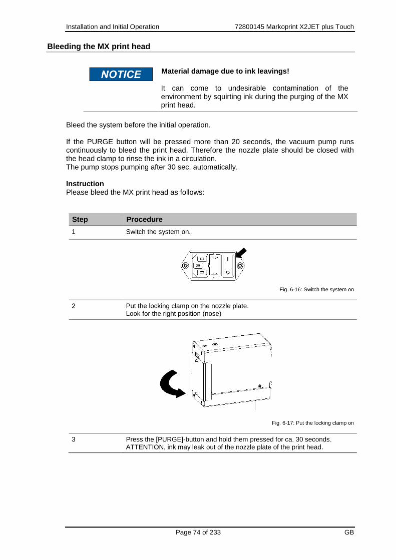
Installation and Initial Operation 72800145 Markoprint X2JET plus Touch
Page 74 of 233 GB
Bleeding the MX print head
Material damage due to ink leavings!
It can come to undesirable contamination of the environment by squirting ink during the purging of the MX print head.
Bleed the system before the initial operation. If the PURGE button will be pressed more than 20 seconds, the vacuum pump runs continuously to bleed the print head. Therefore the nozzle plate should be closed with the head clamp to rinse the ink in a circulation. The pump stops pumping after 30 sec. automatically. Instruction Please bleed the MX print head as follows:
Step Procedure
1 Switch the system on.
Fig. 6-16: Switch the system on
2 Put the locking clamp on the nozzle plate. Look for the right position (nose)
Fig. 6-17: Put the locking clamp on
3 Press the [PURGE]-button and hold them pressed for ca. 30 seconds. ATTENTION, ink may leak out of the nozzle plate of the print head.

Installation and Initial Operation 72800145 Markoprint X2JET plus Touch
Page 75 of 233 GB
Step Procedure
Fig. 6-18: Purge the nozzles
3 Remove the locking clamp from the nozzle plate and store it in a convenient place.
Fig. 6-19: Remove the locking clamp

Installation and Initial Operation 72800145 Markoprint X2JET plus Touch
Page 76 of 233 GB
Rinsing the MX print head
Material damage due to ink leavings!
Rinsing of the MX-Top print head results increased ink consumption and can lead to undesirable contamination of the environment.
Therefore:
– Secure the environment against leaking ink.
– Afterwards wipe the nozzle plate once with a lint-free cloth
Rinse the system before the initial operation. With a short push on the button it happen a flush run, the vacuum pump of the maintenance station runs to suck off the ink rests. The vacuum pump runs after ca. 1 sec. shortly to rinse ink, air and dust from the nozzles, afterwards the vacuum pump runs ca. 10 sec. to suck off the ink rests completely. Instruction Please rinse the MX print head as follows:
Step Procedure
1 Press the [PURGE] button on the system flange plate.
After rinsing, a test print should be done. If the print result is not satisfactory, repeat steps bleeding and rinsing.

Installation and Initial Operation 72800145 Markoprint X2JET plus Touch
Page 77 of 233 GB
Inserting the HP ink cartridge
If a new ink cartridge is inserted, the cartridge counters must be reset. Chapter Reset ink counter, page 159 Use the ink cartridge as soon as possible after having removed the protective foil or the CartClip. Instruction Please insert the HP ink cartridge in the print head as follows:
Step Procedure
1 Remove the protective foil from the nozzle plate and insert the ink cartridge in the cartridge holder.
2 Before replacement of the cartridge, wipe the nozzle plate once with a lint-free cloth.
3 Insert the ink cartridge diagonal in the cartridge holder (see Fig. 6-20).
Fig. 6-20: Inserting the ink cartridge
4 Click the ink cartridge by lightly pressure at the end.
Fig. 6-21: Fixing of the ink cartridge
The correct position of the ink cartridge is displayed in the main menu. The LED lights green after resetting the cartridge counter and after inserting a new ink cartridge.
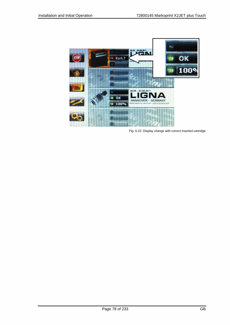
Installation and Initial Operation 72800145 Markoprint X2JET plus Touch
Page 78 of 233 GB
Fig. 6-22: Display change with correct inserted cartridge

Installation and Initial Operation 72800145 Markoprint X2JET plus Touch
Page 79 of 233 GB
Removing the HP ink cartridge
Material damages by misuse!
An electronic fault can’t waive with a going print process and simultaneous removing of the cartridge.
Therefore:
– Only change the cartridge when the print process is stopped.
Instruction Please remove the HP ink cartridge from the print head as follows:
Step Procedure
1 Press diagonal upwards at the end of cartridge.
2 Tip the cartridge from behind upwards (see Fig. 6-23)
Fig. 6-23: Remove the HP ink cartridge

Installation and Initial Operation 72800145 Markoprint X2JET plus Touch
Page 80 of 233 GB
Inserting the LX ink cartridge
The actual ink level of each ink cartridge is percental shown in the main menu. The ink level of Lexmark ink cartridges will be saved in the ink cartridge and must not reset when a new ink cartridge is inserted. Thereby the control system identifies the actual ink level of the partially empty ink cartridge. The ink level of the ink cartridge will be saved in 7% steps. The exactly value of the actual used cartridge will be saved in the control system related to the print head module. This can result an inaccuracy by an inserting in different print head modules. Use the ink cartridge as soon as possible after having removed the protective foil. Instruction Please insert the LX ink cartridge in the print head as follows:
Step Procedure
1 Remove the protective foil from the nozzle plate and insert the ink cartridge in the cartridge holder.
2 Before replacement of the cartridge, wipe the nozzle plate once with a lint-free cloth.
3 Bring the stop lever for the ink cartridge in the unlocked position.
4 Insert the ink cartridge in the cartridge holder (see Fig. 6-24).
Fig. 6-24: Insert the LX ink cartridge
5 Bring the stop lever for ink cartridges in the locked position.

Installation and Initial Operation 72800145 Markoprint X2JET plus Touch
Page 81 of 233 GB
The correct position of the ink cartridge is displayed in the main menu. The LED lights green after a correct insertion. If a used ink cartridge is inserted, the ink level will be shown automatically.
Fig. 6-25: Display change with correct inserted cartridge

Installation and Initial Operation 72800145 Markoprint X2JET plus Touch
Page 82 of 233 GB
Removing the LX ink cartridge
Material damages by misuse!
An electronic fault can’t waive with a going print process and simultaneous removing of the cartridge.
Therefore:
– Only change the cartridge when the print process is stopped.
Instruction Please remove the LX ink cartridge from the print head as follows:
Step Procedure
1 Unlock the stop lever for the ink cartridge.
2 Pull the ink cartridge in the direction of the clamp lever and remove it upwards. (see Fig. 6-26)
Fig. 6-26: Remove the LX ink cartridge

Installation and Initial Operation 72800145 Markoprint X2JET plus Touch
Page 83 of 233 GB
Configuration of the print technology
The Markoprint X2JET plus Touch can control the print technologies HP, LX and MX. The Markoprint X2JET plus Touch has two channels, which provide a combination of the different print technologies. After the system has been installed, the configuration of the print technologies is shown and can set up with the first switch on ( Chapter Switch on, page 85). The configuration of the selectable print technologies is possible like shown in the following list.
Configuration of channels
1 – 2 Description
HP – HP The system controls HP print head modules exclusively. Up to two print head modules are selectable.
HP – MX The system controls one HP print head module and one MX print head module.
MX – MX The system controls MX print head modules exclusively. Up to two print head modules are selectable.
MX – LX The system controls one MX print head module and one LX print head module.
LX – LX The system controls LX print head modules exclusively. Up to two print head modules are selectable.
LX - HP The system controls one LX print head module and one HP print head module.
The Markoprint X2JET plus Touch control system is configured to HP – HP standard by the delivery and can customize to the desired configuration if needed.
Requirements
The print system is correct installed.
The print system is connected to the power supply.
Instruction
Please adjust the configuration of the print technology as follows:
Step Procedure
1 Switch the system on. Chapter Switch on, page 85
2 The display shows the company logo and changes to the configuration menu.
Fig. 6-27: Configuration menu print technology

Installation and Initial Operation 72800145 Markoprint X2JET plus Touch
Page 84 of 233 GB
3 Set the desired print technology for channel 1 (Chan1) by the navigation keys
.
4 Change to channel 2 (Chan2) by the navigation key and set it like
described in step three.
5 After the desired configuration, change to Ok by the navigation key and
set the value to Yes by the navigation key .
6 Press the OK-button to confirm and finish the procedure.
7 The system restarts and reboot in the adjusted configuration.
If a system is false configured or should be reconfigured, the start display can be reactivated for the configuration of the print technology.
Instruction
Please call up the print technology configuration as follows:
Step Procedure
1 Press the function key [F4] in the main menu to call up the service menu.
2 After call up the service menu, press the [CTRL] - and [=] –keys at the same
time.
The display shows short a waiting picture and returns to the service menu
automatically.
3 Switch the system off. Chapter Switch off, page 86
4 Switch the system on. Chapter Switch on, page 85
5 Configurate the system like described above.
The user has in the sub menu Print head configuration ( Chapter Print head configuration, page 156) the option to adapt the settings in the control system with the configuration of the print heads. I.e. it will set which type of print head is connected to the system, e.g. two separate print heads (Single) or a dual print head (Twin).

Operation 72800145 Markoprint X2JET plus Touch
Page 85 of 233 GB
7. Operation
Switch on
Requirements
The print system is connected with power.
Instruction
Please switch the print system on as follows:
Step Procedure
1 Set the switch from 0 to I on the back of the control system.
Fig. 7-1: ON-/OFF-Switch on the top of the control system
2 The controller must conduct a self-test and briefly indicates the unit version number after the company logo has passed through the display. After approx. 20 seconds the status menu-1 appears on the display.
When starting the system unit the progress of the starting process can be monitored on the LED’s. If errors occur during booting, an error code is transmitted via the LED’s and can be analysed in more detail. Chapter Boot-LED messages, page 203 The configuration of the print technology must be set with the initial operation. Here the system doesn’t boot up completely for now, first the configuration of the print technology must performed. Chapter Print technology configuration, page 83

Operation 72800145 Markoprint X2JET plus Touch
Page 86 of 233 GB
Switch off
Requirements
The print system is connected with power and switched on
Instruction
Please switch the print system off as follows:
Step Procedure
1 Set the switch from I to 0 on the back of the control system.
Fig. 7-2: ON-/OFF-switch on the back of the control system

Operation 72800145 Markoprint X2JET plus Touch
Page 87 of 233 GB
Menu navigation
On the right side of the display are the buttons for menu navigation, which allow the user to navigate within the menus and enable to make settings.
About the up / down arrow key movements are performed within the menu and
changed after selecting with the right / left arrow keys to set values. In some
menus it’s also possible to insert values by the keypad directly. Press the OK-button after menu selection, enter the desired value by the keypad and confirm with the OK-
button . The Menu button is placed below the arrow buttons. Pressing the menu button takes you back to the main menu with the status displays.
Fig. 7-3: Menu navigation keys
On the left side of the display are five function keys, which enable the operator to enter the sub-menus. In the sub-menus the function keys are used for print head selection for that settings should be made. Furthermore, in the main menu a print start or print stop can be set by pressing the first function key on the top. By pressing the last function button in submenu you make a move one level back. The respective assignment of function keys is displayed directly next to the display and the menu changes depending on the level.
Fig. 7-4: Function keys
Navigation keys
Function keys

Operation 72800145 Markoprint X2JET plus Touch
Page 88 of 233 GB
Menu navigation Markoprint X2JET plus Touch
The operation of the Markoprint X2JET plus Touch happened by a 5,7” resistive touch with a high-resolution display. The touch responds to pressure, so that it can operate with gloves or a stylus. The Markoprint X2JET plus Touch can operate via the touch-optimized full keyboard and also via the function keys. The operation structure corresponds 1:1 the X2JET plus. Press on the top (scroll up) or the bottom (scroll down) picture to move within the menu. If the top or bottom picture is pressed longer, you scroll through the whole menu automatically.
Fig. 7-5: X2JET Touch Menu navigation
The operator can see the status of the separate print heads in the main menu. By pressing the print head symbol once, the print heads can select separately. The actual load print images will be shown in a preview. If the print image is longer than in the preview displayed, the operator can view the loaded print image by pressing on the left or right half of the print image.
Fig. 7-6: X2JET Touch print image preview

Operation 72800145 Markoprint X2JET plus Touch
Page 89 of 233 GB
If the operator pressed the print head symbol twice, a dialog with the current print image name, the number of the previously print image and the number of prints of the selected print image, which can be print with a full cartridge, appears. The dialog disappears after ca. 5 seconds. A blue circle signalizes the operator by pressing the touch surface that the pressure point is detected correct. After unhand the touch surface the blue circle shrinks to a point, which shows the center point of the pressure range.

Operation 72800145 Markoprint X2JET plus Touch
Page 90 of 233 GB
Indicator lights
Indicator lights on the control system
LED’s, which light up in different colours according to the operating mode, are located on the left side of the display. The LED’s for status sensor, network and Warning are characterized with symbols. The meaning of the different coloured messages is explained in the table below.
Fig. 7-7: Indicator lights
Symbol Function Description Reason
Sensor-LED
GREEN: Active YELLOW:Start signal present RED: Failure
Lights from start to print end No print text No encoder signal
Network-LED
GREEN: O.K. YELLOW: Active RED: Failure
Connected Data transfer
System-Status
GREEN: O.K. YELLOW:Warning RED: Failure
All heads OK One or more Print heads warning One or more Print heads failure
Network
Warning
Sensor

Operation 72800145 Markoprint X2JET plus Touch
Page 91 of 233 GB
Status lights in the main menu
In the main menu are three status lights for each print head modules mapped, which inform about the status of print start, the print head module and ink level of cartridge.
Fig. 7-8: Indicator lights in the main menu
Status panel Display / Description Reason
Upper status panel
Sensor / Encoder
No display
Busy
Signal
Failure Encoder
Displayed when OK, print is not active.
Active print
With print stop and piled sensor.
No shaft encoder connected, but activated in the system.
Middle status panel
Print head module
OK
Pause
Warning
Failure cartridge
Ready for print
Print stop / pause
Not text assigned
No cartridge, cartridge empty, cartridge defect
lower status panel
Cartridge
OK
Warning
Alarm
Ink level 100% to 6%
Ink level below 5%
Cartridge empty

Operation 72800145 Markoprint X2JET plus Touch
Page 92 of 233 GB
Menu structure
Depending on the print head type, certain menus look different or are unavailable.
LABEL
Select print image
Print start Print stop
PARAMETE
R Print position
Encoder
Intensity
Zoom
Print direction
Nozzle rows
Upside down
Head adjustment
Speed
SYSTEM
Date
Time
Language
Spitting Impulse
Spitting
time
Intern / Encoder
Sensor
Print head config
MAC Address
Gate way
Net-Mask
IP-Address
SERVICE
Brightness
USB-Stick

Operation 72800145 Markoprint X2JET plus Touch
Page 93 of 233 GB
INK MENU
Spitting
Reset ink
counter
Warming
Ink type

Operation 72800145 Markoprint X2JET plus Touch
Page 94 of 233 GB
Display Menu Description
Print In the main menu a print start or print stop can be set by pressing the first function key.
Print images can select before print start and added with variable data.
Parameter Print start delay, print speed, divider encoder, intensity, zoom, print direction,
selection of nozzle row, upside down and Head adjustment can be set in this
menu.
Print delay The print start delay can be set in this menu, i.e. by how much is printing delayed in millimetres after the product is detected by the light barrier. Chapter Print start delay, page 103
Speed If the product speed is extremely uniform, the use of the rotary encoder may be dispensed with. For this purpose, the speed can be set in the Speed
submenu by setting Encoder Intern in the system menu. NOTE: This menu is only available if Encoder Intern is set in the menu.
Chapter To set constant print speed, page 105
Encoder When the rotary encoder is connected the pulse per inch can be
set to synchronise the printing speed.
NOTE: This menu is only available if Encoder Intern is set in the menu.
Chapter To set the encoder resolution, page 107
Intensity The contrast of the print image can be set in the print intensity menu. A higher
intensity gives greater blackening and longer ink drying time.
Zoom In the print width menu point, the number of pixels is increased or reduced. The print image is therefore made wider or narrower.
Chapter To set the Zoom, page 109
Direction The parameter print direction indicates the direction of movement of the
product on the conveyor belt viewed from the controller in the print direction.
Chapter Print direction, page 110
Nozzle Each ink cartridge has two rows of nozzles (A and B), for which different settings can be made in the Nozzle Menu. NOTE: Only available for HP and Lexmark print heads
Chapter Nozzle row, page 110
Upside down The setting Upside Down causes the print image to be printed upside down.
Chapter Upside down, page 112

Operation 72800145 Markoprint X2JET plus Touch
Page 95 of 233 GB
Display Menu Description
Head adjustment
The setting head adjustment compensated mechanical imprecisions by multi head applications.
Chapter Head adjustment, page 113
Label Print images can be create, change, delete and select for print.
Chapter Print image, page 114
Display/Setting for selected print head module
Service The settings save data, load data into the memory of the X2JET plus and adjust the display brightness can be made in the service menu.
USB-Stick Load data from the USB stick to the memory of the X2JETplus or save data from the X2JETplus to the USB stick in the USB-stick menu. NOTE: This menu is only busy with an connected USB stick.
Brightness The display brightness can be set in this menu.
Chapter Displayhelligkeit, page 146
System System settings can be made in this menu.
Date The date is displayed in this menu and can be set here.
Chapter Date, page 147
Time The time is displayed in this menu and can be set here.
Chapter Time, page 147
Spitting Impulse
In the menu Spitting impulses the setting whether and how many spit
impulses should been done when the device is switched on, or will be
performed before applying the print. Chapter Spitting Impulse, page 148
Spitting time In this sub-menu can be set in which time between two prints, a spitting is performed
Chapter Spitting time, page 149

Operation 72800145 Markoprint X2JET plus Touch
Page 96 of 233 GB
Display Menu Description
Internal Pulse / Encoder
The print speed must correspond to the conveyor belt speed. To ensure this it can be set in the Internal Pulse print head submenu how this is
predetermined. Intern means that the predetermined speed of the conveyor belt is kept constant, and Extern means that the exact transport speed is transmitted to the controller by the optionally available encoder.
Chapter Internal Pulse print head, page 150
Sensor In this sub menu can be set which sensor input is used.
Chapter Select sensor, page 152
IP-Address The IP address is indicated in this menu.
Chapter IP address, page 153
Net-Mask Indication of net mask.
Chapter Net-Mask, page 154
Gate-Way Indication of Gateway address.
Chapter Gate-Way, page 155
MAC Adresse Indication of MAC address.
Chapter MAC-address, page 155
Print head configuration
In sub-menu head configuration, the operator can control the settings in the device which has to adapt the structural configuration of the print heads. Chapter Print head configuration, page 156
Language
In this menu the language can be set as desired.
Ink menu Reset ink counter, purge, warming and the ink type can be set in this menu Depending on the print head type there are different submenus.
Reset ink counter
This function causes the ink level to be reset after inserting a new cartridge. (Print head specific). NOTE: Only available for HP print heads.
Chapter Reset ink counter, page 159

Operation 72800145 Markoprint X2JET plus Touch
Page 97 of 233 GB
Display Menu Description
Purge During the purging process ink is ejected from all the nozzle ducts.
WARNING: Protect the environment from pollution!
Chapter To rinse the nozzles manually, page 160
Warming Indication of the temperatures and calibration of the warming setting. NOTE: The calibration isn’t possible for LX print heads, the correction will be
done by the system automatically. This menu point displays in this case the temperature only. This menu point isn’t available for MX print heads.
Chapter Warming, page 161
Ink type In this menu can be set up the used ink type. This effects an automatically set up of all relevant parameters. Depending on the application it’s necessary to fit the parameters. The parameter is variable adjustable for print head 1+2 and 3+4 by pairs. This setting isn’t possible for LX print heads, the ink type will be automatically detected by the system.
Chapter Set ink type, page 163
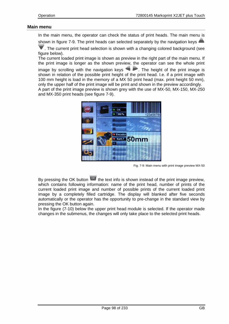
Operation 72800145 Markoprint X2JET plus Touch
Page 98 of 233 GB
Main menu
In the main menu, the operator can check the status of print heads. The main menu is
shown in figure 7-9. The print heads can selected separately by the navigation keys
. The current print head selection is shown with a changing colored background (see figure below). The current loaded print image is shown as preview in the right part of the main menu. If the print image is longer as the shown preview, the operator can see the whole print
image by scrolling with the navigation keys . The height of the print image is shown in relation of the possible print height of the print head. I.e. if a print image with 100 mm height is load in the memory of a MX 50 print head (max. print height 50 mm), only the upper half of the print image will be print and shown in the preview accordingly. A part of the print image preview is shown grey with the use of MX-50, MX-150, MX-250 and MX-350 print heads (see figure 7-9).
Fig. 7-9: Main menu with print image preview MX-50
By pressing the OK button the text info is shown instead of the print image preview, which contains following information: name of the print head, number of prints of the current loaded print image and number of possible prints of the current loaded print image by a completely filled cartridge. The display will blanked after five seconds automatically or the operator has the opportunity to pre-change in the standard view by pressing the OK button again. In the figure (7-10) below the upper print head module is selected. If the operator made changes in the submenus, the changes will only take place to the selected print heads.

Operation 72800145 Markoprint X2JET plus Touch
Page 99 of 233 GB
Fig. 7-10: Main menu with status display
The Markoprint X2JET plus Touch technology enables a combination of different print technologies, which must configured from the user with the initial operation. ( Chapter Configuration of the print technology of the print technology, page 83). Furthermore the user has, like described in Chapter Print head configuration, page 156 the option to configure the connected print head modules. The figure (7-10) above shows the configuration of a Markoprint X2JET plus as LX system, that is set as two Single print heads in the print head configuration. The figure 7-11 shows also the configuration of a Markoprint X2JET plus Touch as LX system, that is set as Twin print head in the print head configuration.
Abb. 7-11: Main menu with status display
The selection of the configuration should match the architectural design of the print heads, otherwise it may lead to an incorrect representation of the printed images. If a change relating to the desired product labelling occurs and an adjustment of the print heads or print technology is necessary, so please contact your local distributor.

Operation 72800145 Markoprint X2JET plus Touch
Page 100 of 233 GB
Password protection: If menues should be protected via password this is possible to activate via iDesign software. See iDesign manual. The user name of the user which is working with password protection will be shown at the bottom left corner. To deactivate a user press the info button or after 2 minutes of inactivity the user will be deactivated.

Operation 72800145 Markoprint X2JET plus Touch
Page 101 of 233 GB
Print start
In the main menu a print start can be set by pressing the top function key. For a print start activation can be differ between following alternatives:
You will start a print image without counter or variable data.
You will continue the print of the last print image with a counter or variable data without input of new data.
You will start to print a new selected print image with a counter and variable data with input of new data.
Instruction
Please activate a print start for a print image without variable fields etc. as follows:
Step Procedure
1 Press once shortly the function key [START] left of the display.
Fig. 7-12: Function key left of the display
2 Select the desired print image by pressing the navigation keys , or by entering the print image name by keypad.
3 Confirm the selected print image by pressing the OK-button .
Instruction
Please activate a print start for the last print image without the input of new data as follows:
Step Procedure
1 Press once shortly the function key [START] left of the display.
Fig. 7-13: Function key left of the display
2 The assignment of keys changes between the individual steps. Please follow the display! Press the function key [START] shortly again left of the display.
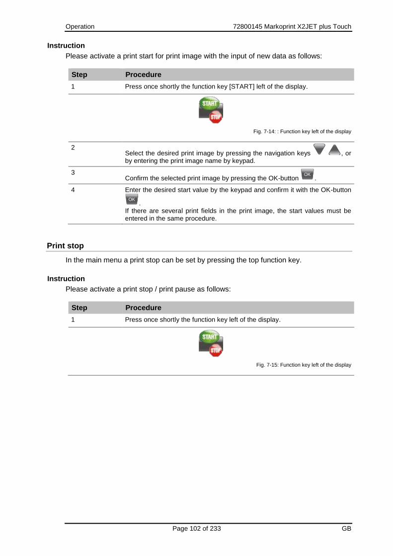
Operation 72800145 Markoprint X2JET plus Touch
Page 102 of 233 GB
Instruction
Please activate a print start for print image with the input of new data as follows:
Step Procedure
1 Press once shortly the function key [START] left of the display.
Fig. 7-14: : Function key left of the display
2 Select the desired print image by pressing the navigation keys , or by entering the print image name by keypad.
3 Confirm the selected print image by pressing the OK-button .
4 Enter the desired start value by the keypad and confirm it with the OK-button
. If there are several print fields in the print image, the start values must be entered in the same procedure.
Print stop
In the main menu a print stop can be set by pressing the top function key.
Instruction
Please activate a print stop / print pause as follows:
Step Procedure
1 Press once shortly the function key left of the display.
Fig. 7-15: Function key left of the display

Operation 72800145 Markoprint X2JET plus Touch
Page 103 of 233 GB
Print start delay
The print start delay can be set in this menu, i.e. by how much is printing delayed in millimeters after the product is detected by the light barrier. The delay can be selected between 0 and 999 millimetres. About iDesign the operator can adjust the left or right edge of the print image as a reference point for print position. . The parameter can be set under button "System Settings" tab "Advanced Settings" submenu "Extra configuration" menu "Delay reverse print". By default, the right edge is taken as reference. By this setting, potential problems are solved in reverse print. The left edge of a short print image would be, under the mentioned conditions in Example 2, at another location on the product, than the left edge of a longer print image, if no adjustment of the printing position would be made. Example 3 shows, that no adjustment of the print position is necessary, to print different long print images at the same position. Example 1: Product direction from right to the left and the left edge of print image as reference point.
Delay Text12345
Delay Text12 Example 2: Product direction from left to the right and the right edge of print image as reference point.
Text12345 Delay
Text12 Delay
Example 3: Product direction from left sight to right sight and the left edge of print image as reference point (with calculation of the print start). Delay
Text12345
Delay
Text12
Please note that the print start delay must be set up bigger than the text length. If the print start delay is set up to small the print layout would be print complete. For example: by a text length of 25 mm the setup of the delay between 0 and 25 mm has no effect.

Operation 72800145 Markoprint X2JET plus Touch
Page 104 of 233 GB
Instruction
Please set up the print start delay in the control system as follows:
Step Procedure
1 Press setting key in main menu.
2 The sub menu Print position appears.
3 Set the desired value by pressing the navigation keys , or press
the OK-button , enter the determined value by the keypad and confirm
with the OK-button .

Operation 72800145 Markoprint X2JET plus Touch
Page 105 of 233 GB
To set constant print speed
The print speed of the print heads must match the conveyor belt speed; otherwise print images may be distorted. There are 2 ways to match the print speed to the conveyor belt speed:
Internal constant print speed
External variable print speed via rotary encoder
The setting of internal / external speed can be set as described under Chapter Internal Pulse print head, page 150. If no rotary encoder is connected to the controller, the conveyor belt speed must be measured or estimated and the determined value entered as a parameter. A test image can then be used for fine-tuning the print speed.
The following parameters must be entered:
Print speed Print speed = Conveyor belt speed. The conveyor belt speed must remain constant!
Print intensity Print image contrast. If necessary, this parameter may have to be changed to optimise the print image to the product surface. Higher intensity means increased density and slower drying of the ink. Default value for HP and LX is 300dpi, 192dpi for MX.
Zoom This parameter enables an increase or decrease of the number of pixels. This renders the print image wider or narrower. The printed image is widened or narrowed even if the DPI setting is changed. This can be prevented when the zoom is in the advanced settings set to "fixed zoom = yes". Then it is printing always 1:1,if setting on the image is 100%, regardless of the DPI setting. This setting should not be used with bar codes, because it can cause distortion. The default is "fixed zoom = No“. About the iDesign software the operator can adjust to the fixed zoom. The setting is the iDesign software under the button "System Settings" tab "Advanced Settings" submenu “periphery" menu item "fixed zoom“.
The maximum speed depends on the intensity: At 600 dpi the print speed may be up to 30 m/min. At 300 dpi the print speed may be up to 60 m/min. At 200 dpi the print speed may be up to 90 m/min. At 150 dpi the print speed may be up to 120 m/min. A print speed 50% higher can be obtained with a rotary transducer. This setting lies outside the specification and must be carefully tested! A double speed can be reached with the High Speed function by the Markoprint X2JET plus Touch Pro version. At a resolution up to 300x300dpi the print speed may up to 180 m/min.

Operation 72800145 Markoprint X2JET plus Touch
Page 106 of 233 GB
Parameter Min. Max. Unit
Print speed 1 400 m/min
Print intensity 50 900 dpi
Zoom 10 900 %
Instruction
Please set the print speed on the control system as follows:
Step Procedure
1 Press setting key in main menu.
2 The sub menu Print position appears.
3 Call up the submenu Speed by pressing navigation key .
4 The sub menu Speed appears.
5 Set the desired conveyor speed value by pressing the navigation keys
or press the OK-button , enter the determined value by the
keypad and confirm with the OK-button .
6 Call up the submenu Zoom by pressing navigation key .
7 The sub menu Zoom appears.
8 Set the desired value by pressing the navigation keys .

Operation 72800145 Markoprint X2JET plus Touch
Page 107 of 233 GB
To set the encoder resolution
If a rotary encoder is connected to the controller, the print speed is automatically matched to the conveyor belt speed through the impulses of the rotary encoder. The following parameters must be entered:
Rotary encoder resolution
the resolution is the number of pulses per inch (ppi).
Intensity
the intensity in dpi (dots per inch).
Printing width
The number of pixel can be increased or decreased using this parameter. The
print image becomes narrower or wider.
Calculation example of rotary encoder resolution: The standard rotary encoder has a friction wheel circumference of 200 mm and generates 5 000 impulses per revolution. If the friction wheel of the rotary encoder runs directly on the belt, the calculation is as follows: 1. Conversion to inches: 200 mm / 25.4 mm = 7.874 inches 2. Resolution of the rotary encoder: 5000 impulses / 7.874 inches = 635 impulses/inch
= 635 dpi 3. To get even finer settings, the pulse will be doubled internal. 4. If you set a divider of 4, you will get a resolution of 318 dpi (635x2/4). This value
must be entered for the intensity. If a standard rotary encoder is mounted directly onto a shaft, the distance to be measured is the distance covered by a product on the conveyor belt during a single rotary encoder revolution (e.g. 300 mm).
5. Conversion to inches: 300 mm / 25.4 mm = 11.81 inches 6. Resolution of the rotary encoder:
5000 impulses / 11.81 inches = 423 impulses/inch x2 = 846 dpi The result of divider 2 is 426 dpi. The calculated value must be then fine-tuned, using the test image. (Speedtest.00I)
Parameter Min. Max. Uniit
Rotary encoder 50 5000 ppi
Print intensity 50 900 dpi
Zoom 10 900 %

Operation 72800145 Markoprint X2JET plus Touch
Page 108 of 233 GB
Instruction
Please set up the variable print speed as follows:
Step Procedure
1 Press system key in main menu.
2 The sub menu Date appears.
3 Call up the submenu Int. Pulse/Encoder by pressing navigation key .
4 The sub menu Int. Pulse/Encoder appears.
5 Set the value on Encoder by pressing Navigation keys .
6 Change by pressing the menu button or the Back button in the main menu.
7 The main menu appears.
8 Press settings key in main menu.
9 The sub menu Print position appears.
10 Call up the submenu Divider Encoder by pressing the navigation key .
11 The sub menu Divider Encoder appears.
12 Set the desired value by pressing the navigation key .
13 This setting is made automatically by using the rotary encoder of Weber Marking Systems GmbH. If another rotary encoder is used or the encoder runs directly on the spindle, the dpi value must be calculated and entered.
14 Call up the sub menu Intensity by pressing the navigation key .
15 The sub menu Intensity appears.
16 Set the desired value by pressing the navigation keys , or press
the OK-button , enter the determined value by the keypad and confirm
with the OK-button .

Operation 72800145 Markoprint X2JET plus Touch
Page 109 of 233 GB
To set the Zoom
The zoom of the print image can be varied with the zoom value. At a zoom of 100%, the print image is printed 1:1 as displayed in the iDesign. With this parameter a change in the size of the print image is achieved. If the parameter is reduced the print image becomes narrower by delaying individual pixel gaps. This compresses the pint image and enables the ink consumption to be reduced. By printing of barcodes you must look out for print optimal with 300 dpi and 100%. Other dpi values or an enlarging or narrowing can cause deformations. By default, the image will be printed in different widths dependent on the adjusted intensity (dpi). The print width can be adjusted by the zoom. The print image is in the width 1:1 with a resolution of 600 dpi. With a resolution of 300 dpi, the print image is more than twice the width 1:2, caused of the halved intensity. Change the zoom to 10% - 900% in the menu. The value can be changed in 1% steps. Pay attention, that a widening or narrowing of barcode prints have the right measure. Follow the chart!
Barcode width Allowed Zoom factors with fixed zoom.
1 100 200 300 400 500 600 …
2 50 100 150 200 250 300 350 …
3 33 66 100 133 166 200 233 266 …
4 25 50 75 100 125 150 175 200 225 …
5 40 60 80 100 120 140 160 180 200 …
6 33 50 66 83 100 116 133 150 166 183 …
Instruction
Please call up the print image as follows:
Step Procedure
1 Press system key in main menu.
2 Call up the submenu Zoom by pressing navigation key.
3 The sub menu Zoom appears.
4 Set the desired value by pressing the navigation keys , or press
the OK-button , enter the determined value by the keypad and confirm
with the OK-button .
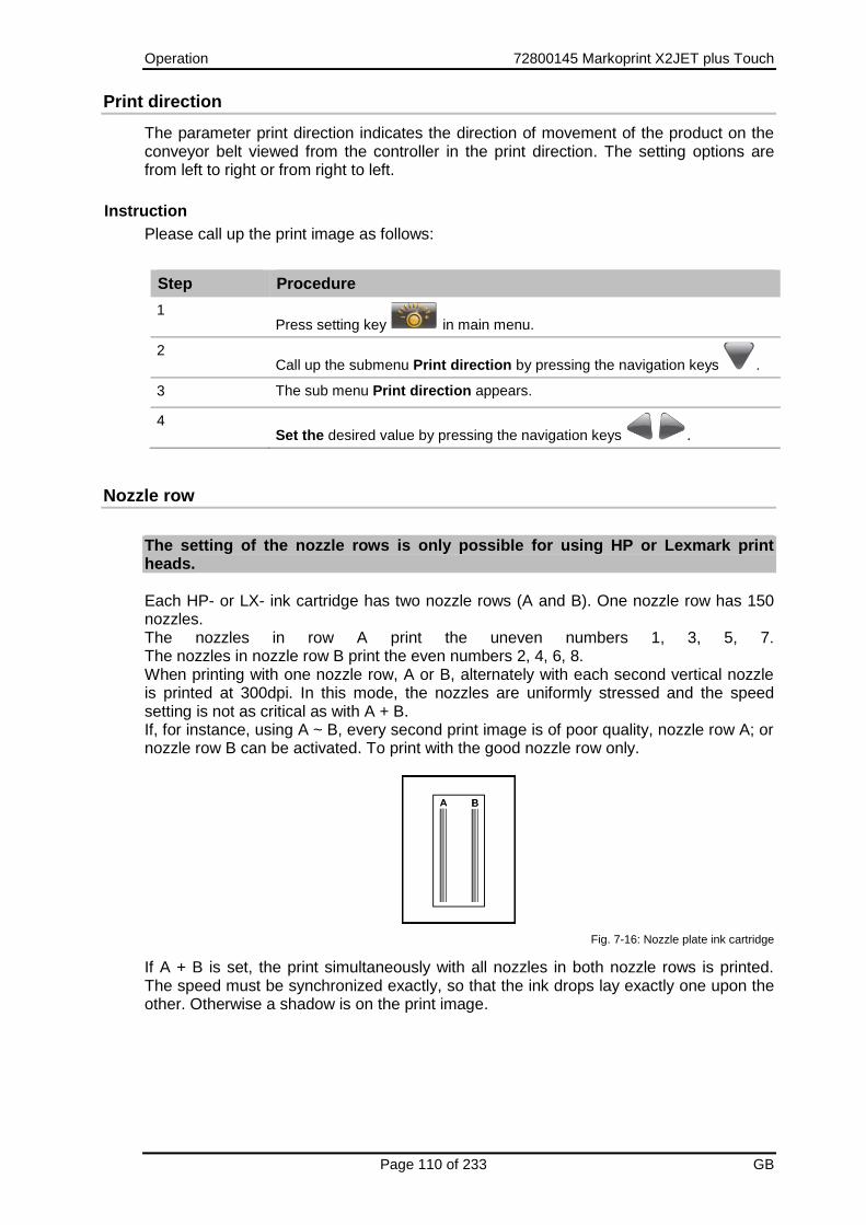
Operation 72800145 Markoprint X2JET plus Touch
Page 110 of 233 GB
Print direction
The parameter print direction indicates the direction of movement of the product on the conveyor belt viewed from the controller in the print direction. The setting options are from left to right or from right to left.
Instruction
Please call up the print image as follows:
Step Procedure
1 Press setting key in main menu.
2 Call up the submenu Print direction by pressing the navigation keys .
3 The sub menu Print direction appears.
4 Set the desired value by pressing the navigation keys .
Nozzle row
The setting of the nozzle rows is only possible for using HP or Lexmark print heads. Each HP- or LX- ink cartridge has two nozzle rows (A and B). One nozzle row has 150 nozzles. The nozzles in row A print the uneven numbers 1, 3, 5, 7. The nozzles in nozzle row B print the even numbers 2, 4, 6, 8. When printing with one nozzle row, A or B, alternately with each second vertical nozzle is printed at 300dpi. In this mode, the nozzles are uniformly stressed and the speed setting is not as critical as with A + B. If, for instance, using A ~ B, every second print image is of poor quality, nozzle row A; or nozzle row B can be activated. To print with the good nozzle row only.
Fig. 7-16: Nozzle plate ink cartridge
If A + B is set, the print simultaneously with all nozzles in both nozzle rows is printed. The speed must be synchronized exactly, so that the ink drops lay exactly one upon the other. Otherwise a shadow is on the print image.

Operation 72800145 Markoprint X2JET plus Touch
Page 111 of 233 GB
Nozzle row Description
A ~ B Printing with both nozzle rows, alternating. The first print image is printed with nozzle row A and the second text with nozzle row B. Vertical resolution: 300 dpi
A + B Printing with both nozzle rows together. Vertical resolution: 600 dpi
A Printing only with nozzle row A. Vertical resolution: 300 dpi
B Printing only with nozzle row B. Vertical resolution: 300 dpi
With setting A + B, the print speed must be accurately set, to produce a good print result. Otherwise the print image is blurred.
Instruction
Please select a nozzle row as follows:
Step Procedure
1 Press setting key in main menu.
2 The sub menu Print position appears.
3 Call up the submenu Nozzle row by pressing navigation key .
4 The sub menu Nozzle row appears.
5 Set the desired value by pressing the navigation keys .
In the Hi-Speed mode (only Markoprint X4JET plus Pro version) the setting of the nozzle rows A~B cannot vary!

Operation 72800145 Markoprint X2JET plus Touch
Page 112 of 233 GB
Upside down
Instruction Please set up the upside down print as follows:
Step Procedure
1 Press setting key in main menu.
2 The sub menu Print position appears.
3 Call up the submenu Upside down by pressing navigation key .
4 The sub menu Upside down appears.
5 Set the desired value by pressing the navigation keys .

Operation 72800145 Markoprint X2JET plus Touch
Page 113 of 233 GB
Head adjustment
A mechanical imprecision between the print head modules / cartridges by multi-head systems can be compensated in this menu. It is maximal +-1 – 2mm, which must be compensated. A value from -50 to +50 can be entered to adjust the respective print head rightward or leftward. The respective print head goes rightward with a + value and leftward with a - value. Requirements: The print head must be installed horizontally. There may not be an overlap or gap between the cartridges. It’s the best to check this with a layout, which goes over all print heads. The print speed must set up optimal. The nozzles A+B must be correct in one row by prints with two nozzle rows. This can be checked with a loupe. There may not be a “shadow print”. Divider and intensity must be set up optimal by printing. The nozzles A+B must be correct in one row by prints with two nozzle rows. This can be checked with a loupe. There may not be a “shadow print.
Procedure
Please proceed as follows to set up a head correction:
Step Procedure
1 Set all values for the head adjustment to „0”.
2 I.e. by a quad head all values for head 1 will set to „0“. Than a test print will made, which goes over all print heads.
3 If there is a horizontally stowing between the first and the second print head module, it can be compensated with the head adjustment of print head 2.
4 Proceed the same way with print head 3 and 4.
5 If there is a stowing after changing the cartridge, correct only the stowing of this cartridge.
Instruction
Please set the head adjustment as follows:
Step Procedure
1 Press setting key in main menu.
2 The sub menu Print position appears.
3 Call up the submenu Head adjustment by pressing navigation key .
4 The sub menu Head adjustment appears.
5 Set the desired value by pressing the navigation keys , or press
the OK-button , enter the determined value by the keypad and confirm
with the OK-button .

Operation 72800145 Markoprint X2JET plus Touch
Page 114 of 233 GB
Print image
Print images can be created, changed, deleted or call up to print in the menu print image creation. Print images are combination of texts, graphics, barcodes and function elements (i.e. counter and variable). Quick guide print image creation
Here you find the quick guide description of an easy print image creation and to call this to print. A print image with the text „Example“ will be created and called for print. Instruction So you create a print image with the text „Example“ and call this to print:
Step Procedure
1
Press the [Print image]-key in the main menu.
2 The menu Print image appears.
Fig. 7-17: Menu print image
3 Press the [New print image]-key .
4 The menu Print image creation appears.

Operation 72800145 Markoprint X2JET plus Touch
Page 115 of 233 GB
Step Procedure
Fig. 7-18: Menu Print image creation
5 Press the [Add text]-key
Fig. 7-19: New text field
6 Enter the text „Example“, or any text via the keyboard. The keyboard works like a standard PC-keyboard.

Operation 72800145 Markoprint X2JET plus Touch
Page 116 of 233 GB
Step Procedure
Fig. 7-20: Text field „Example“
7 Press once the navigation-key to change the font size.
8 Press the navigation-keys to set up the desired font size.
In the example Fig. 7-21 was „A8mmB“ selected. This means font Arial with a
height of 8mm in Bold design.
Fig. 7-21: Print image creation font size
9 Press twice the [Back]-key to call up the memory name.
10 Insert a memory name via keyboard.
In the example in Fig.7-20 the print image was saved under the name
„Example“.

Operation 72800145 Markoprint X2JET plus Touch
Page 117 of 233 GB
Step Procedure
Fig. 7-22: Print image creation memory name
11 Press the [Save]-key for saving.
12 Press the [Start]-key to call up for print.
13 The print image is shown in the print image preview in the main menu.
Fig. 7-23: Print image preview in the main menu
14 If the print image is bigger than the representation of the standard-preview,
press the navigation-keys to view the whole print image.
Operation 72800145 Markoprint X2JET plus Touch
Page 118 of 233 GB
Loading print image
Instruction Please load a print image for print as follows:
Step Procedure
1
Press Print image key in the main menu.
2 The sub menu Print image appears.
3 Select the print image by pressing the navigation keys , or enter the
name of the desired print image by the keypad.
4 If the print image is longer as the display preview, it is possible to the whole
print image by pressing the navigation keys .
5 Confirm the selected print image by pressing the [START]-button.
6 The display changes to the main menu and the selected print image is shown
in the preview of the main menu and is print by activation of the sensor.

Operation 72800145 Markoprint X2JET plus Touch
Page 119 of 233 GB
Change print image
Instruction Please change an available print image as follows:
Step Procedure
1
Press the Print image-key in the main menu.
2 The submenu Print image appears.
3 Make a print image selection by pressing the navigation-keys or
insert the name of the desired print image via keyboard.
4 If the print image is bigger than the representation of the standard-preview,
press the navigation-keys to view the whole print image.
5 Press the key to change the selected print image .
Fig. 7-24: Menu Change print image
6 Select the print field, which should be changed by pressing the navigation-
keys .
The selected print field is marked with a red frame and a blue display of the
field content.
7 Press the [OK]-key to confirm.
8 There are different settings depending on the selected print field.
The setting possibilities are shown below the print image and can leaf through
the navigation-keys .
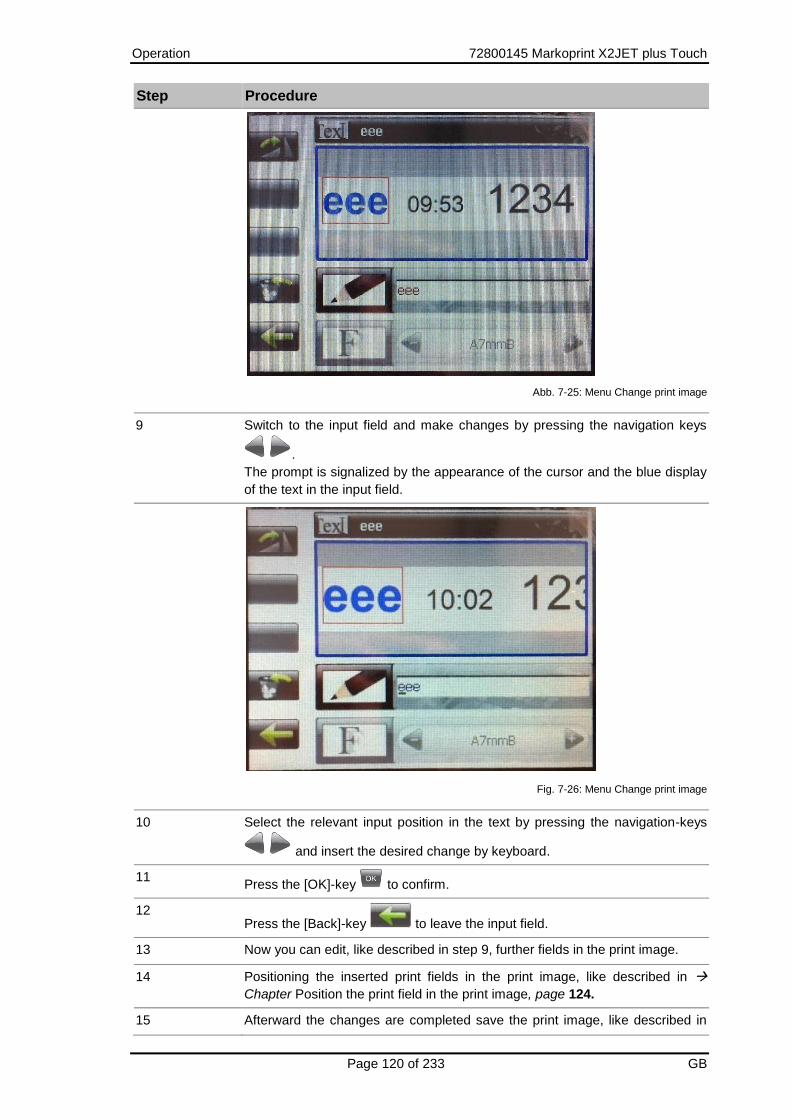
Operation 72800145 Markoprint X2JET plus Touch
Page 120 of 233 GB
Step Procedure
Abb. 7-25: Menu Change print image
9 Switch to the input field and make changes by pressing the navigation keys
.
The prompt is signalized by the appearance of the cursor and the blue display
of the text in the input field.
Fig. 7-26: Menu Change print image
10 Select the relevant input position in the text by pressing the navigation-keys
and insert the desired change by keyboard.
11 Press the [OK]-key to confirm.
12 Press the [Back]-key to leave the input field.
13 Now you can edit, like described in step 9, further fields in the print image.
14 Positioning the inserted print fields in the print image, like described in
Chapter Position the print field in the print image, page 124.
15 Afterward the changes are completed save the print image, like described in

Operation 72800145 Markoprint X2JET plus Touch
Page 121 of 233 GB
Step Procedure
Chapter Save print image, page 126.

Operation 72800145 Markoprint X2JET plus Touch
Page 122 of 233 GB
Create a new print image
A print image comprises of different elements and fields:
Text
Logo
Barcode
Date
Time
Variable
Counter
Action fields
Instruction
Please create a new print image as follows:
Step Procedure
1
Press the [Print image]-key in the main menu.
2 The menu Print image appears.
Fig. 7-27: Menu Print image
3 Press the [New print image]-key .
4 The menu Print image creation appears.

Operation 72800145 Markoprint X2JET plus Touch
Page 123 of 233 GB
Step Procedure
Fig. 7-28: Menu Print image creation
5 Add a new field or several new fields and make the field specific settings as
desired.
Following fields can insert in the print image:
Text
Logo
Barcode
Date
Time
Variable
Counter
Please note the following chapter.
6 Positioning the inserted print fields in the print image, like described in
Chapter Position the print field in the print image, page 124.
7 Afterward the print image creation is completed save the print image, like
described in Chapter Save print image, page 126.

Operation 72800145 Markoprint X2JET plus Touch
Page 124 of 233 GB
Position the print field in the print image
A print field can positioned as follows:
Free positioning of a print field in the print image, i.e. move pixel by pixel.
Positioning the print field by align with the boundary area of the print image and the boundary area of other print fields.
Instruction
Positioning the print field in the print image pixel by pixel as follows:
Step Procedure
1 Select first the print field, which should positioned, by the navigation-keys
.
2 Press the [Step]-key .
3 Now the print field can free positioned by the navigation-keys
.
4 Press the [OK]-key , or the [Back]-key to close the process.
5 After the creation process is closed, save the print image, like described in
Chapter Save print image, page 126.
Instruction
Please position a print field with the help of the boundary area of the print image or other print fields:
Step Procedure
1 Select first the print field, which should positioned, by the navigation-keys
.
2 Press the [Step]-key twice.
3 The print field can now align with the navigation-keys on
the boundary areas of the print image and the boundary areas of other print
fields in the print image.
4 Press the [OK]-key , or the [Back]-key to close the process.
5 After the creation process is closed, save the print image, like described in
Chapter Save print image, page 126.

Operation 72800145 Markoprint X2JET plus Touch
Page 125 of 233 GB
Turn a print field in the print image
Not all fields can turned, i.e. 2D-codes can’t turned.
Instruction
Please turn a print field in the print image as follows:
Step Procedure
1 Select first the print field, which should positioned, by the navigation-keys
.
2 Press the [Turn]-key .
3 The print field will be turned through 90° clockwise with each keypress.
4 Press the [OK]-key , or the [Back]-key to close the process.
5 After the creation process is closed, save the print image, like described in
Chapter Save print image, page 126.

Operation 72800145 Markoprint X2JET plus Touch
Page 126 of 233 GB
Save print image
Instruction
Please save a new or changed print image as follows:
Step Procedure
1 After you have created/changed the print image as desired, press the [Back]-
key to leave the menu.
2 It appears a prompt for input of a memory name.
3 You have following possibilities:
Save the print image under the same name (if a print image
was changed or a new created should replace the existing one)
Save the print image under a new name.
Abolish the changes.
Return to the print image change.
To save the print image under a new name, insert a new name by the
keyboard and press the [Save]-key.
To save the print image under the same name, press the [Save]-key. The print
image data of the changed print image will be overwrote!
To abolish the changes, press the [Delete]-key and confirm it by pressing the
[Delete]-key again. The assignment of keys change during the delete process
– Follow the display.
To return to the print image change, press the [Back]-key.

Operation 72800145 Markoprint X2JET plus Touch
Page 127 of 233 GB
Insert a text field in the print image
Static texts will be inserting in the print image as text fields.
Requirements
You are in the menu print image creation. See Chapter Create new print image, page 122
Instruction
Please insert a new text field in the print image as follows:
Step Procedure
1 Press the key [Add text]
Fig. 7-29: New text field
2 Insert the desired text via the keyboard. The keyboard works like a standard PC-keyboard. If a text field should be changed, note Chapter Change print image, page 119
3 Insert the text „Example“, or any text via the keyboard and confirm it by
pressing the [OK]-key .
Fig. 7-30: Text field „Example“

Operation 72800145 Markoprint X2JET plus Touch
Page 128 of 233 GB
Step Procedure
4 Press once the navigation-key to change the font size.
5 Press the navigation-keys to set up the desired font size.
In the example Fig. 7-21 was „A8mm“ selected. This means font Arial with a
height of 8mm in Bold design.
6 Position the inserted print field in the print image, like described in Chapter
Position the print field in the print image, page 124.
7 After the creation process is closed, save the print image, like described in
Chapter Save print image, page 126.
Ask your local distributor for further fonts.

Operation 72800145 Markoprint X2JET plus Touch
Page 129 of 233 GB
Insert a date field in the print image
A date is embedded in the print image as a date field. Date fields are not static, but dynamic fields; their display format is defined by variables. The current date is retrieved from the system clock. By printing the current date will be also obtained from the system clock. Any combination of variables can be used to configure the display format. Punctuation marks (e.g. full stop, colon, hyphen, space etc.) can be inserted between the individual codings. ab.cd.gh are preset.
Variable Description Display
ab-cd-gh Date 22-05-11
efgh Year 2011
ij:kl:mn Time 11:20:35
ooo Month as string Jan
ppp Day of the year 135
q Weekday 4
rr Calendar week 28
s Hour as string k
You can find the whole list of all date/time formats in the appendix. Chapter Date variables, page 200 Date and time formats can be combined. Forward dating, for instance to print a best before date (BBD), can be defined by the offset parameters year, month and day.
Requirements
You are in the menu print image creation. See Chapter Create a new print image, page 122
Instruction
Please insert a new date field in the print image as follows:
Step Procedure
1 Press the [Add variable field]-key .
2 Press the [Add date field]-key .
3 The date field appears in the print image.

Operation 72800145 Markoprint X2JET plus Touch
Page 130 of 233 GB
Step Procedure
Fig. 7-31: Menu print image creation date field
4 Change the input mask of the date field by pressing once the right navigation-
key .
5 Adapt the image of the date as desired. The introduction of the chapter will
help.
6 Press the [OK]-key to confirm.
7 Press the navigation-key once to change to the selection field for the font
size.
8 Press the navigation-keys to set the desired font size.
9 Change to the selection field for date offset by the day by pressing the
navigation-key once.
10 Set the date offset by day as desired by pressing the navigation-keys
or by direct input via the keyboard.
The date offset by day can set between 0 and +9999 days.
11 If the date offset was inserting by keyboard, press the [OK]-key to
confirm.
12 Change to the date offset by month by pressing the navigation-key .
13 Set the date offset by month as desired by pressing the navigation-keys
or by direct input via the keyboard.
The date offset by month can set between 0 and +99 months.
14 If the date offset was inserting by keyboard, press the [OK]-key to
confirm.
15 Change to the date offset by year by pressing the navigation-key .

Operation 72800145 Markoprint X2JET plus Touch
Page 131 of 233 GB
Step Procedure
16 Set the date offset by year as desired by pressing the navigation-keys
or by direct input via the keyboard.
The date offset by year can set between 0 and +99 years.
17 If the date offset was inserting by keyboard, press the [OK]-key to
confirm.
18 Change to the display field of the field number by pressing the navigation-key
once. This is needed for action field links.
The field number will be generate automatically and can’t change with the
creation of date fields.
19 Position the inserted print field in the print image, like described in Chapter
Position the print field in the print image, page 124.
20 After the creation process is closed, save the print image, like described in
Chapter Save print image, page 126.

Operation 72800145 Markoprint X2JET plus Touch
Page 132 of 233 GB
Insert a time field in the print image
The time is embedded in the print image as a time field. Time fields are not static, but dynamic fields; their display format is defined by variables. The current time is retrieved from the system clock. By printing the current time will be also obtained from the system clock. Any combination of variables can be used to configure the display format. Punctuation marks (e.g. full stop, colon, hyphen, space etc.) can be inserted between the individual codings. ij:kl:mn are preset.
Variable Description Display
ij:kl:mn Time 11:20:35
Variable Description
i Hour, tens
j Hour, ones
k Minute, tens
l Minute, ones
m Second, tens
n Second, ones
You can find the whole list of all date/time formats in the appendix. Chapter Date variables, page 200 Date and time formats can be combined.
Requirements
You are in the menu print image creation. See Chapter Create a new print image, page 122
Instruction Please insert a new time field in the print image as follows:
Step Procedure
1 Press the [Add variable field]-key .
2 Press the [Add time field]-key .
3 The time field appears in the print image.

Operation 72800145 Markoprint X2JET plus Touch
Page 133 of 233 GB
Step Procedure
Fig. 7-32: Menu Print image creation time field
4 Change the input mask of the time field by pressing once the right navigation-
key .
5 Adapt the image of the time as desired. The introduction of the chapter will
help.
6 Press the [OK]-key to confirm.
7 Press the navigation-key once to change to the selection field for the font
size.
8 Press the navigation-keys to set the desired font size.
9 By pressing the navigation-key , the menu runs through some settings, which are necessary by a combination of date- and time field. See Chapter Insert a date field in the print image, page 129
10 Press the navigation-key several times to see a field number at the end of the input-menu. This is needed for action field links. The field number will be generate automatically and can’t change with the creation of time fields.
11 Position the inserted print field in the print image, like described in Chapter
Position the print field in the print image, page 124.
12 After the creation process is closed, save the print image, like described in
Chapter Save print image, page 126.

Operation 72800145 Markoprint X2JET plus Touch
Page 134 of 233 GB
Insert a variable field in the print image
Variables are inserted in the print image by means of variable fields. Variable fields are used if a print image contains data (e.g. batch numbers) that change frequently. This can be automated, shortly before the print image is released for printing. The operator can insert a new variable value in the variable field before a print image is called or the old text retained. It is possible to enter several variable fields in a text.
Requirements
You are in the menu print image creation. See Chapter Create a new print image, page 122
Instruction
Please insert a variable field in the print image as follows:
Step Procedure
1 Press the [Add variable field]-key .
2 Press the [Add variable field]-key .
3 The variable field appears in the print image.
Fig. 7-33: Menu Print image creation variable field
4 Press the navigation-keys to set the desired font size.
5 Change to the input field for the variable specification by pressing the navigation-
key once.
6 Insert the variable specification as desired in the input field.
Please note the description, which follow this instruction!
7 Change to the input field for the nomination of the variable field by pressing the
navigation-key .
The nomination of the variable field appears in the prompt by print start of the print
image.
The nomination makes sense if several variable fields are contained in the print

Operation 72800145 Markoprint X2JET plus Touch
Page 135 of 233 GB
Step Procedure
image. This can be better vary from the prompt after print start.
8 Name the variable field as desired, i.e. with batch number.
9 Change to the display field of the field numbers by pressing the navigation-key
once. This is needed for action field links.
The field number will be generate automatically and can’t change with the creation
of date fields.
10 Position the inserted print field in the print image, like described in Chapter
Position the print field in the print image, page 124.
11 After the creation process is closed, save the print image, like described in
Chapter Save print image, page 126.
There are some alternatives for an input available, which have different effects:
The standard registered „?“ in the input field will be deleted and the variable is insert with a certain number of characters: With every print start of the print image appears a prompt of the variable data. You can see the inserted text of the variable field in the input field. This can be adapt or overwrite. Any characters can be inserted when overwriting, but it will only accept so many characters like make in the variable specification.
The variable specification in the input field will not change and the standard registered „?“ is insert in the input field: It appears a prompt of the variable data with every print start of the print image. You can insert any text with any length.
The standard registered „?“ is registered in the input field and the variable specification will be added with a number of characters: It appears a prompt of the variable data with every print start of the print image. The inserted text of the variable field can be seen in the input field. This can be adapt or overwrite. Any characters can be inserted when overwriting.
Via the delivered iDesign software the setting can make, with a connection between PC and software, whether the variable specification of the print image creation appears static with the print start in the prompt or whether the entry of the last print start appears. The setting can be made in the iDesign software like shown in Fig. 7-34. Therefore please note the delivered manual of the software!

Operation 72800145 Markoprint X2JET plus Touch
Page 136 of 233 GB
Fig. 7-34: iDesign Save variable fields

Operation 72800145 Markoprint X2JET plus Touch
Page 137 of 233 GB
Insert a counter field in the print image
The counters are inserted in the print image through counter fields. Counter fields are inserted to print consecutive numbers on labels i.e.: labels must be print. When starting to print, the counter starting value appears in the first print. When reaching the end count, the counter re-starts at the starting value. If the end value is smaller than the starting value, counting is downward. Example 1: Starting value: 01, end value: 10, step size: 2, repeats: 3 Print: 01, 01, 01, 03, 03, 03, 05, 05, 05.... Example 2: Starting value: 10, end value: 1, step size 1, repeats: 0 Print: 10, 9, 8, 7....1, 10, 9, 8, 7....
Requirements
You are in the menu print image creation. See Chapter Create a new print image, page 122
Instruction
Please insert a new counter field in the print image as follows:
Step Procedure
1 Press the [Add variable field]-key .
2 Press the [Add counter field]-key .
3 The counter field appears in the print image.
Fig. 7-35: Menu Print image creation counter field
4 Press the navigation-keys to set the desired font size.
5 Change to the input field for the counter start value by pressing the navigation-key
once.
6 Enter the desired counter start value via the keyboard and confirm with the [OK]-

Operation 72800145 Markoprint X2JET plus Touch
Page 138 of 233 GB
Step Procedure
key , or set the counter start value by pressing the navigation-keys .
The counter start value can set between 0 and 99999999.
Please note the description, which follow this instruction!
7 Change to the input field for the counter end value by pressing the navigation-key
.
Enter the desired counter end value via keyboard and confirm with the [OK]-key
, or set the counter end value by pressing the navigation-keys .
The counter end value can set between 0 and 99999999.
Change to the input field for the counter step size by pressing the navigation-key
.
Insert the desired counter step size via keyboard and confirm with the [OK]-key
, or set the counter step size by pressing the navigation-keys .
The counter step size can set between 0 and 99999999.
Change to the input field for the print repeat of the counter by pressing the
navigation-key .
Insert the desired number of print repeat of counter via keyboard and confirm with
the [OK]-key , or set the print repeat by pressing the navigation-keys .
The print repeat can set between 0 and 9999.
The field number is shown at the end of the input-menu by pressing the navigation-
key . This is needed for action field links. The field number will be generate automatically and can’t change with the creation
of counter fields.
Position the inserted print field in the print image, like described in Chapter
Position the print field in the print image, page 124.
After the creation process is closed, save the print image, like described in
Chapter Save print image, page 126.
There are some alternatives for an input available, which have different effects: Via the delivered iDesign software the setting can make, with a connection between PC and software how the counter start value will be specified by print start. Following options are available:
Specification of the start value from the print image.
Specification of the start value by user input.
Specification of the start value by the last start value.
Specification of the start value by the last start value or by user input. The setting can take in the iDesign software, like shown in Fig. 7-36. Therefore please note the delivered manual of the software!
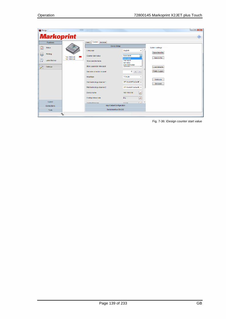
Operation 72800145 Markoprint X2JET plus Touch
Page 139 of 233 GB
Fig. 7-36: iDesign counter start value

Operation 72800145 Markoprint X2JET plus Touch
Page 140 of 233 GB
Insert a logo in the print image
Graphics (logos) can be inserted in a print image as logo or bitmap files. The created bitmap files must be monochrome BMP! The table below shows the file type and the available pixel height for the different print head types. The numbers of pixels refer to the full print height of the print head. For example: 256 with the Maxiline 100 for 100mm height. A logo with 64 pixels would be 25 mm high.
Print head type File type Max. pixel height
MX 50 Bitmap 128/print head
MX 100 Bitmap 256/ print head
HP Bitmap 300/ink cartridge
LX Bitmap 300/ ink cartridge
Via the delivered iDesign software the logos can send to the control system, with a connection between PC and software. See Fig. 7-37. Therefore please note the delivered manual of the software!
Fig. 7-37: iDesign Send logos
Requirements
You are in the menu print image creation. See Chapter Create a new print image, page 122

Operation 72800145 Markoprint X2JET plus Touch
Page 141 of 233 GB
Instruction
Please insert a new logo in the print image as follows:
Step Procedure
1 Press the [Add logo]-key .
2 Press the navigation-keys to select the desired logo and confirm with
the [OK]-key .
3 Position the inserted print field in the print image, like described in Chapter
Position the print field in the print image, page 124.
4 After the creation process is closed, save the print image, like described in
Chapter Save print image, page 126.

Operation 72800145 Markoprint X2JET plus Touch
Page 142 of 233 GB
Insert a barcode in the print image
A barcode is machine-readable writing comprising of parallel lines and gaps of various widths. The data in the barcode can also be displayed in plain text, legible to humans, in a line of plain text directly below the barcode. If the barcode cannot be read, the data can be evaluated manually. iDesign offers a range of barcode and 2D Code types, depending on the selected printer:
Barcode type Description Stellen
EAN 8 Numerical commercial barcode; used worldwide. 8
EAN 13 Numerical commercial barcode; used worldwide. 13
EAN 128 Numerical commercial logistics code. Variable fields for date, counter and scale as options.
max. 70
Code 128 Full ASCII barcode; medical-pharmaceutical technology. max. 70-
Code 2 of 5 Numerical industrial (materials-handling) barcode,
always with even number of digits. Also designated 2/5
interleaved, ITF 2/5)
min. 2 max.40
DUN 14 * Numerical industrial barcode (materials-handling) 14
UPC A UPC E
Same as EAN 13, but special 1st digit code.
Is normally set to 0 followed by 11 digit code. The 13th digit is an automatically generated test digit. Used in USA/Canada.
13
Code 39 Alphanumeric barcode for industry, electronics,
pharmaceutical.
max.40
UCC Same as Code 2 of 5. For trading in the USA. 14
Data Matrix A 2D code for the electronics industry and
pharmaceutical sector.
max.256
EAN Data Matrix A 2D code for the electronics industry and
pharmaceutical sector.
max.256
QR Code A 2D-code for Japan and Marketing purposes specially max.256
PPN-Code Pharmacode max.256
GS1 Databar Omnidirectional 16
GS1 Databar Expanded max. 70
Requirements
You are in the menu print image creation. See Chapter Create a new print image, page 122
Instruction
Please insert a new barcode in the print image as follows:
Step Procedure
1 Press the [Add Barcode/Datamatrix-Code]-key .

Operation 72800145 Markoprint X2JET plus Touch
Page 143 of 233 GB
Step Procedure
2 Press the [Barcode]-key .
3 Select the desired barcode-type by pressing the navigation-keys .
4 Change to the input field for the barcode by pressing the navigation-key .
5 Geben Sie den gewünschten Dateninhalt des Barcodes über die Tastatur ein.
6 Change to the selection field for the plain text font size of the barcode by
pressing the navigation-key .
7 Press the navigation-keys to set the desired font size for the plain
text.
8 Change to the selection field for the barcode height by pressing the
navigation-key .
9 Insert the desired barcode height via keyboard and confirm with the [OK]-key,
or set the barcode height by pressing the navigation-keys .
10 Change to the selection field for the line width of the barcode by pressing the
navigation-key .
11 Insert the desired barcode line width via keyboard and confirm with the [OK]-
key, or set the barcode line width by pressing the navigation-keys .
12 Position the inserted print field in the print image, like described in Chapter
Position the print field in the print image, page 124
13 After the creation process is closed, save the print image, like described in
Chapter Save print image, page 126.

Operation 72800145 Markoprint X2JET plus Touch
Page 144 of 233 GB
Insert a 2D-code in the print image
Requirements
You are in the menu print image creation. See Chapter Create a new print image, page 122
Instruction
Please insert a new 2D-code in the print image as follows:
Step Procedure
1 Press the [Add Barcode/Datamatrix-Code]-key .
2 Press the [Datamatrix]-key .
Select the desired 2D-code type by pressing the navigation-keys .
Change to the input field for the 2D-code by pressing the navigation-key .
Insert the desired data content of the 2D-code via keyboard.
Change to the selection field of the 2D-code size by pressing the navigation-
key .
Insert the 2D-code size via keyboard and confirm with the [OK]-key or set the
desired 2D-code size by pressing the navigation-keys .
Change to the selection field for the dot-size of the 2D-code by pressing the
navigation-key .
Insert the desired 2D-code dot size via keyboard and confirm with the [OK]-
key, or set the 2D-code dot size by pressing the navigation-keys .
Position the inserted print field in the print image, like described in Chapter
Position the print field in the print image, page 124.
2D-Codes can’t be turned!
After the creation process is closed, save the print image, like described in
Chapter Save print image, page 126.

Operation 72800145 Markoprint X2JET plus Touch
Page 145 of 233 GB
USB-Stick
Load data from the USB stick to the memory of the X4 JET plus or save data from the X4 JET plus to the USB stick in the USB-stick menu. This menu is only busy with an connected USB stick. Instruction Please change data between USB-stick and control system as follows:
Step Procedure
1 Press the Service key in the main menu.
2 The submenu USB-Stick appears.
3 Insert the USB stick.
4 The submenu USB-Stick is shown.
5 Select the desired memory method by pressing the navigation keys
and confirm with .
Following memory methods are available:
Data backup from Markoprint X2JET plus Touch to USB-Stick:
Display Description
Texts Save the texts, which are stored in the Markoprint X2JET plus Touch, to an USB-Stick.
Backup Backup of all data on an USB-stick
Parameter Backup of the adjusted parameter value.
Data transfer from USB-stick to the memory of the Markoprint X2JET plus Touch:
Display Description
Texts Transfer the stored texts from the USB stick to the memory of the Markoprint X2JET plus Touch.
Restore Transfer the data backup from the USB-stick to the memory of the Markoprint X2JET plus Touch.
Parameter Transfer the parameter values, which are stored on the USB-stick, to the memory of the Markoprint X2JET plus Touch.
Fonts Transfer the fonts, which are stored on the USB-stick, to the memory of the Markoprint X2JET plus Touch.

Operation 72800145 Markoprint X2JET plus Touch
Page 146 of 233 GB
Brightness
The display brightness can be set in this menu.
Instruction
Please set the display brightness as follows:
Step Procedure
1 Press the service key in the main menu.
2 The submenu USB-Stick appears.
3 Call up the submenu Brightness by pressing the navigation key .
4 Set the Brightness by pressing the navigation keys , or press the
OK-button , enter the desired value by the keypad and confirm with the
OK-button .

Operation 72800145 Markoprint X2JET plus Touch
Page 147 of 233 GB
Date
In this menu the date is been shown and can be adjusted. Instruction Please set the date as follows:
Step Procedure
1 Press the System key in the main menu.
2 The sub menu Date appears.
3 Set the date by pressing the navigation keys and confirm with the
OK key , or press the OK-button , enter the determined value by the
keypad and confirm with the OK-button .
Time
In this menu the time is been shown and can be adjusted. Instruction Please set the time as follows:
Step Procedure
1 Press the System key in the main menu.
2 The sub menu Date appears.
3 Call up the submenu Time by pressing navigation key .
4 The sub menu Time appears.
5 Set the time by pressing the navigation keys and confirm with the
OK key , or press the OK-button , enter the determined value by the
keypad and confirm with the OK-button .

Operation 72800145 Markoprint X2JET plus Touch
Page 148 of 233 GB
Spitting Impulse
Property damage caused by squirting ink!
The spitting can result in unwanted contamination of the environment.
The spitting leads to an increased ink consumption. In the menu spitting impulse the operator can set, whether and how many spit impulses will be performed when the device is switched on, or before applying the print. Depending on the settings, the Spit impulse effects an ejection of ink drops between 1 - 100, with a clock rate of 2 kHz from each nozzle. This may be necessary for ink types with lower drying time, to avoid drying out the nozzles and ensure a good print start. In the following chapter "Spitting time" the operator can adjust, whether a pulse-Spitting is executed or not, depending on the elapsed time between the prints. For example: It could be advisable to adjust the value to 20 spit impulses and 30 seconds spit time. This means that the printing of all products 1-29 seconds nothing happens. Only 30 seconds after no product is passing, the spitting is performed once before the next printing with 20 pulses.
Instruction
Please set the spit impulse as follows:
Step Procedure
1 Press the System key in the main menu.
2 The sub menu Date appears.
3 Call up the submenu Spit pulse by pressing navigation key .
4 The sub menu Spit pulse appears.
5 Set the desired value by pressing the navigation keys .

Operation 72800145 Markoprint X2JET plus Touch
Page 149 of 233 GB
Spitting time
In this sub menu is set, after which time a spitting operation is run between two prints. The setting Spitting impulse would be necessary for reasons mentioned in Chapter Spitting impulses. The values range from 1 - to set 999 seconds. Instruction Please set the spitting time as follows:
Step Procedure
1 Press the System key in the main menu.
2 The sub menu Date appears.
3 Call up the submenu Spitting time by pressing navigation key .
4 The sub menu Spit pulse appears.
5 Set the desired value by pressing the navigation keys .

Operation 72800145 Markoprint X2JET plus Touch
Page 150 of 233 GB
Internal Pulse print head
The print speed must relate to the conveyor speed. If the conveyor speed is constant, the print speed can adjust fix, otherwise a shaft encoder should be used, which measure the conveyor speed and adapt the print speed continuous. The Markoprint X2JET plus Touch has two channels, which enable the connecting two encoders to the control unit. I.e. there are two independently operating signals available to align the print speed. One channel is for the print head modules 1 are available and the other channel for the print head modules 2. By this procedure it is possible to print with head modules 1 and 2 on a production line and with print modules 3 and 4 on another production line with a different speed. If both channels should work with the same encoder, the signal from head 1 +2 can be coupled to the signal head 3 +4. The following settings are possible:
Display Channel Description
1 In this setting, the print speed for print head modules 1 is determined with an internal pulse.
1 In this setting, the print speed for print head modules 1 is determined with an encoder.
2 In this setting, the print speed for print head modules 2 (independently of the print head modules 1) set with an internal pulse.
2 In this setting, the print speed for print head modules 2 (independently of the print head modules 1) set with an encoder.
2 In this setting, the print speed for print head modules 2 is coupled to the input of the print head modules 1.
If internal pulse setting is chosen, the speed of conveyor belt must be determined and entered into the controller. Enter the determined conveyor belt speed as described under Chapter To set the encoder resolution, page 107.
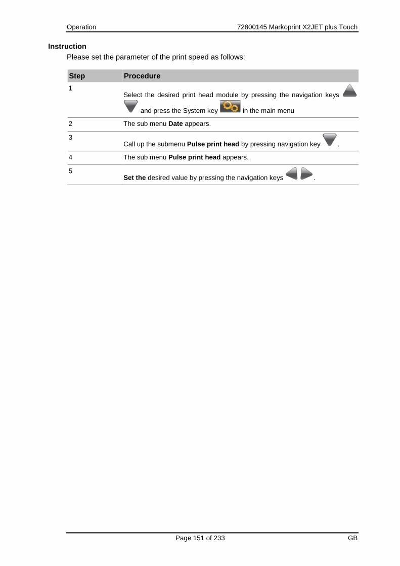
Operation 72800145 Markoprint X2JET plus Touch
Page 151 of 233 GB
Instruction
Please set the parameter of the print speed as follows:
Step Procedure
1 Select the desired print head module by pressing the navigation keys
and press the System key in the main menu
2 The sub menu Date appears.
3 Call up the submenu Pulse print head by pressing navigation key .
4 The sub menu Pulse print head appears.
5 Set the desired value by pressing the navigation keys .
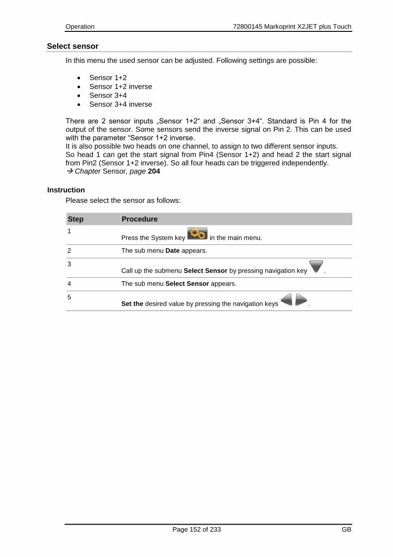
Operation 72800145 Markoprint X2JET plus Touch
Page 152 of 233 GB
Select sensor
In this menu the used sensor can be adjusted. Following settings are possible:
Sensor 1+2
Sensor 1+2 inverse
Sensor 3+4
Sensor 3+4 inverse There are 2 sensor inputs „Sensor 1+2“ and „Sensor 3+4“. Standard is Pin 4 for the output of the sensor. Some sensors send the inverse signal on Pin 2. This can be used with the parameter “Sensor 1+2 inverse. It is also possible two heads on one channel, to assign to two different sensor inputs. So head 1 can get the start signal from Pin4 (Sensor 1+2) and head 2 the start signal from Pin2 (Sensor 1+2 inverse). So all four heads can be triggered independently. Chapter Sensor, page 204
Instruction
Please select the sensor as follows:
Step Procedure
1 Press the System key in the main menu.
2 The sub menu Date appears.
3 Call up the submenu Select Sensor by pressing navigation key .
4 The sub menu Select Sensor appears.
5 Set the desired value by pressing the navigation keys .

Operation 72800145 Markoprint X2JET plus Touch
Page 153 of 233 GB
IP address
In this sub menu the IP-address is displayed, or can set here.
Instruction
Please show / adjust the IP address in the menu as follows:
Step Procedure
1 Press the System key in the main menu to select the desired heads.
2 The sub menu Date appears.
3 Call up the submenu IP-address by pressing navigation key .
4 The sub menu IP-address is displayed.
5 Activate the input by press .
6 Set the IP address by the keypad.
If not all characters are needed in the justify, it can be changed to the
next justify with the navigation keys.
7 Confirm with .

Operation 72800145 Markoprint X2JET plus Touch
Page 154 of 233 GB
Net-Mask
In this sub menu the Net-Mask is displayed, or can set here.
Instruction
Please set / show the Net-Mask in the menu:
Step Procedure
1 Select the desired print head module by pressing the navigation keys
and press the System key in the main menu
2 The sub menu Date appears.
3 Call up the submenu Net-Mask by pressing navigation key .
4 The sub menu Net-Mask is displayed.
5 Activate the input by press .
6 Set the Net-Mask by the keypad.
If not all characters are needed in the justify, it can be changed to the
next justify with the navigation keys.
7 Confirm with .

Operation 72800145 Markoprint X2JET plus Touch
Page 155 of 233 GB
Gate-Way
In this sub menu the Gate-Way-address is displayed, or can set here.
Instruction
Please show / set the Gate-Way-address in the menu as follows:
Step Procedure
1 Select the desired print head module by pressing the navigation keys
and press the System key in the main menu
2 The sub menu Date appears.
3 Call up the submenu Gate way address by pressing navigation key .
4 The sub menu Gate-Way-Address appears.
5 Activate the input by press .
6 Set the Gate-Way address by the keypad.
If not all characters are needed in the justify, it can be changed to the
next justify with the navigation keys.
7 Confirm with .
MAC-address
In this sub menu the MAC-address is displayed.
Instruction
Please show the MAC-address on the system as follows:
Step Procedure
1 Select the desired print head module by pressing the navigation keys
and press the System key in the main menu
2 The sub menu Date appears.
3 Call up the submenu MAC-address by pressing navigation key .
4 The sub menu MAC-address appears.

Operation 72800145 Markoprint X2JET plus Touch
Page 156 of 233 GB
Print head configuration
The Markoprint X2JET plus Touch has on the input side two channels, which provide the controller unit with signals for sensor, encoder, and outputs an alarm signal on the output side (e.g. for connecting an alarm lamp). I.e. there are two independently operating signals for triggering print, alignment of the print speed and to issue alerts available. One channel is for the print head modules 1 available and the other channel for the print head modules 2. Furthermore, the connections to the print head modules are also split into two channels. About this procedure, the simultaneous control of different printing technologies is realized. The configuration of the selectable print technologies will be delivered as HP – HP standard. The configuration of the print technologies is shown and can set up with the first switch on of the system. Chapter Configuration of the print technology, page 83. The configuration of the selectable print technologies is possible like mentioned in the table below.
Configuration of channels
1 - 2 Description
HP – HP The device controls at only HP print head modules. Up to two print head modules can be controlled.
HP – MX The device controls one HP print head modules and one MX print head modules.
MX – MX The device controls at only MX print head modules. Up to two print head modules can be controlled.
MX – LX The device controls one MX print head modules and one LX print head modules.
LX – LX The device controls at only LX print head modules. Up to two print head modules can be controlled.
LX - HP The device controls one LX print head modules and one HP print head modules.
In sub menu head configuration, the operator can adjust the configuration in the device, which has to be in accordance with the structural configuration of the print heads. The possible combinations are at this point, even for a HP - HP device configuration exemplified:
Configuration HP – HP:
Configuration Description
2x Single Two single print heads with one input or output port for the print head modules 1 and 2 the print head modules.
1x Twin One twin print head with one input/output port for the print head modules 1 +2.

Operation 72800145 Markoprint X2JET plus Touch
Page 157 of 233 GB
Instruction
Please configure the print heads as follows:
Step Procedure
1 Press the System key in the main menu.
2 The sub menu Date appears.
3 Call up the submenu Head Configuration by pressing navigation key .
4 The sub menu Head Configuration appears.
5 Select the desired channel by pressing the corresponding function keys.
6 Set the head configuration as desired by pressing the navigation keys
.
The selection of the configuration should match the architectural design of the print heads, otherwise it may lead to an incorrect representation of the printed images. If a change relating to the desired product labelling occurs and an adjustment of the print heads or print technology is necessary, so please contact your local distributor.

Operation 72800145 Markoprint X2JET plus Touch
Page 158 of 233 GB
User language
It is possible to switch the user language of the Markoprint X2JET plus Touch to English, German, or other languages.
Instruction
Please set the user language as follows:
Step Procedure
1 Press the System key in the main menu.
2 The sub menu Date appears.
3 Call up the submenu Select language by pressing navigation key .
4 The sub menu Select user language appears.
5
Select the desired language by pressing the navigation key and confirm
with .

Operation 72800145 Markoprint X2JET plus Touch
Page 159 of 233 GB
Reset ink counter
The reset of the ink counter is only possible for using HP print heads. In HP MK2 and LX cartridges the ink level is detected automatically. This menu isn’t available by using MX print heads. Reset the ink counter after inserting a new ink cartridge. Each ink cartridge is displayed in main menu with its current ink level as a percentage.
Instruction
Please reset the ink counter as follows:
Step Procedure
1 Call up the ink menu by pressing the ink key ..
2 Call up the submenu Ink reset by pressing the navigation key .
3 Set the value to „YES“ by pressing the navigation keys and confirm
with .
In LX cartridges, the ink level is stored in an internal memory of the cartridge and does not need a reset if new cartridge is used. The controller knows the current ink level of the cartridge. The ink is stored in 7% increments. The exactly value of the actual used cartridge will be saved in the control system related to the print head module. This can result an inaccuracy by an inserting in different print head modules. In HP MK2 cartridges, the ink level is stored in the SmartCard Chip of the cartridge and does not need a reset if new cartridge is used. The controller knows the current ink level of the cartridge. The ink is stored in 1% increments. The automatic storage of ink level only works with distributed Ink cartridges by Weber Marking Systems. Only ink cartridges by Weber Marking Systems are supported by the print heads.

Operation 72800145 Markoprint X2JET plus Touch
Page 160 of 233 GB
Calculate ink content HP cartridge
A HP ink cartridge contains 42 ml of ink, equivalent to 1.26 billion ink droplets of approx. 33 pl each. The system counts the ink droplets printed and uses this to calculate the ink consumption. This function is only correct if the ink meter is reset when a new HP ink cartridge is inserted. The ink content can also be determined by weighing: A full HP cartridge weighs approx. 110 g ± 3 g. An empty cartridge weighs approx. 70 g ± 5 g. The residual ink in an empty cartridge is 3 ml max.
Calculate ink content LX cartridge
A LX ink cartridge contains ca. 1,083 bn ink droplets of approx. 24 pl each. The system counts the ink droplets printed and uses this to calculate the ink consumption. The number of prints, which can be done with one cartridge, can be read in the menu. The ink content can also determine by weighing: A full LX cartridge weighs ca. 66 g ± 3 g. An empty cartridge weighs ca. 40 g ± 3 g. The rest of an empty cartridge is max. 3 ml.
To rinse the nozzles manually
Material damage due to squirting ink!
The spitting can result in unwanted contamination of the environment.
Therefore:
– Hold a moist cloth in front of the ink cartridge nozzle plate.
After extended periods of no printing, it may be necessary to rinse the ink cartridges to open up clogged nozzle ducts again. During rinsing (purging), all ink cartridge nozzle ducts are addressed to eject some ink. The rinse process takes max. 2 seconds or rather so long as the button will be pressed and hold.
Requirements
Absorbent cloth
Or paper / cardboard
Instruction
Please rinse the nozzle channels as follows:
Step Procedure
1 Call up the ink menu by pressing the ink key .
2 Call up the menu item Spitting by pressing the navigation key
3 Set the value “YES” (OK) by pressing the navigation keys .

Operation 72800145 Markoprint X2JET plus Touch
Page 161 of 233 GB
Step Procedure
4 Hold a moist cloth or a sheet of paper in front of the ink cartridge nozzle plate!
5 The spit impulse is activate by pressing the OK-button and proceed as long as the key will be pressed.
Warming
Material damages due to false settings of the warming function!
It is important to ensure that the warming is not turned on accidentally, as this can cause damage to the cartridge or a defective printed image.
Therefore:
– Do not set the warming accidentally.
Warming can be used to increase the print quality and enhance the restart printing. The Warming can be activated by the iDESIGN software. The adjustment is in the iDesign software under button „System settings“ tab „Advanced settings“ sub menu „Warming“ menu „Warming“. If the warming is activated, the cartridges must be calibrated. The calibration of the cartridge (temperature sensor in the cartridge) is necessary because the sensors in the cartridge have large tolerances. The calibration is only necessary when the cartridges are changed. The calibration of the warming is only necessary when HP print heads are used. When the warming function for LX- print heads is switched on, the correction is made automatically. The Warming menu serves only to display the temperature. This menu isn’t available by using MX print heads. The calibration is performed by Markoprint X2JET plus Touch in the System menu
where also the ink level can reset.
Configuration Description
Ambient temperature – Temperature of the HP-Board in the head housing.
Head temperature – Temperature of the nozzle plate.
Head-ID – Identification number is used for service.
In the line head temperature (Hd. Temp) the current temperature in the cartridge is displayed. If a value over 100 (149 or similar) is displayed there is no cartridge or a defective cartridge is inserted. After the calibration, the head temperature (Hd. Temp) shows the same value as the ambient temperature (Ab. Temp) which reference sensor is located on the HP board in
Operation 72800145 Markoprint X2JET plus Touch
Page 162 of 233 GB
the print head module. The temperature of the HP board is about 5 ° C higher than the actual ambient temperature because the board warms up in the print head housing. While the Warming menu is open, the warming is turned off. When the menu is left, the warming will be reactivated. Only calibrate cartridges with ambient temperature. Very cold or warm cartridges falsify the result. It is the best to observe the temperature for a while (about a minute) if the temperature is stable. By every cartridge replacement (using a new cartridge), you have to reset the ink level, so that the ink calculation / ink warning is working properly and calibration must be performed.
Instruction
Please calibrate the head temperature as follows:
Step Procedure
1 Call up the ink menu by pressing the ink key .
2 Call up the submenu Warming by pressing navigation key .
3 The Head temperature is calibrated by pressing the OK key .

Operation 72800145 Markoprint X2JET plus Touch
Page 163 of 233 GB
Set ink type
Depending on the application is the use of a specific ink type necessary. The different characteristics of the inks need an individual setting of the Markoprint X2JET plus Touch. If HP MK2 or LX print heads are used, the ink type will be detected by the control system automatically and takes the ink specific settings. The automatic setting of the ink type works only with ink cartridges sold by Weber Marking Systems! Ink cartridges, which are not distributed by Weber Marking Systems will not supported by the print heads. If HP print heads are used, the setting must be done from the user directly on the Markoprint X2JET plus Touch- control system. Therefore the Markoprint X2JET plus Touch have under the menu item select ink type the possibility to choose basic settings. Certainly it’s necessary to adapt special settings, dependent on the application. The setting of the ink type must accord with the ink type of the used cartridge. Otherwise there are incorrect presentations of print images. Instruction Please set the ink type as follows:
Step Procedure
1 Call up the ink menu by pressing the ink key .
2 Call up the submenu Ink type by pressing navigation key .
3 Set the desired ink type by pressing the navigation keys .

Operation 72800145 Markoprint X2JET plus Touch
Page 164 of 233 GB
Web-Interface
There is the option to make settings on the Markoprint X2JET plus Touch by the Web browser via a PC, which is connected with the Markoprint X2JET plus Touch. On this the IP of the respective system has to be entered in the address bar of the Web browser. Possibly other settings had to make on the PC to have access to the IP address. (system administrator) The system IP can be read or rather set up on the system directly. Chapter IP address, page 153 The Web interface don’t support all function at the moment!
Fig. 7-38: User interface Web-Interface
To set up the parameters, please enter the username. Username: user Password: 1234 If you cannot change the parameters, the functions are not unlock, i.e. HiSpeed in the Advanced version. Layouts can’t be created with the WEB interface.

Operation 72800145 Markoprint X2JET plus Touch
Page 165 of 233 GB
Configurable inputs and Outputs
The Markoprint X2JET plus Touch- controller offers the possibility of the M12 (ALARM) and the 15-pin SUB-D connector (EXTERNAL) to use as additional inputs / outputs. The used pins of the pin assignment Chapter Plug connection, page 204. A variety of configurations are possible and so the connectors for output of status messages (OK, Warning, Error), cartridge level messages (5% low / empty), print ready and print pulse are possible to use. On the input side signals for heating, spitting, print direction, upside print, stop and text selection are possible. The settings can be done by the iDesign software below Functions System settings Advanced settings or by the Web-Browser below Settings Advanced settings.
Fig. 7-39: User interface Software iDesign

Operation 72800145 Markoprint X2JET plus Touch
Page 166 of 233 GB
NonStopPrinting
With the use of a NonStopPrinting print head (NSP head) it’s possible to print without interruptions. The NSP head consists of 2 cartridges, each of them print on the same position. If one cartridge is empty or is to be cleaned, the other cartridge prints continuously.
Fig. 7-40: Example for a NSP Single print head LX
Description:
Each print head consists of two cartridge holders, which are controlled alternately. Both cartridges are so driven that they print on the same position of the product. The cartridges have 100% ink capacity at the installation. The first cartridge prints two times successive, the second cartridge prints once alternately, so that both cartridges aren’t empty simultaneously. The alternately printing at the rate of 1:2 prevents a drying up of the cartridges. If the cartridge with the higher print volume is empty, a warning will be displayed and the other cartridge prints continuously from now until a new cartridge is replaced. The new cartridge prints now in a less volume than the other cartridge, so this needs to be replaced next. The print head is wider by the double cartridge holder (ca. 68 mm with LX print head) as a normal print head (ca. 34 mm). In addition to a NSP Single print head with a print height of 12,5 mm there is also a NSP Twin print head with a print height of 25 mm. I.e. at a X4JET / X4JET plus can connect one or two NSP Single print heads or one NSP Twin print head. HP and LX NSP print heads are available. Print systems of customer can be operated efficiently and economically with the use of the NonStopPrinting function by an elimination of production downtimes. Services and repairs of defect print heads can be done during the running production.

Operation 72800145 Markoprint X2JET plus Touch
Page 167 of 233 GB
System setting:
The system must set up to the NSP function. That can be done by the iDesign software below Settings System NonStopPrinting. If the function isn’t need, the seeting must be set to „Off“. A Single head (12,5mm) could be connected at channel 1 A shaft encoder is recommended for a correct synchronisation.
Setup:
Example: A Single head at channel 1 Please set first the encoder resolution or speed exactly. The test print image „Speedtest“ can be used as an assistance. For testing switch NSP off and set the system to 2x Single. Assign both heads the same print image. Both cartridges might be print on the same position. For a fine-tuning adjust shaft encoder resolution or speed. Then switch on the NSP and assign one of the cartridges the print image.
Start and assign print image:
To assign a print image one of the both cartridges must select firstly. Move in the print image selection with the function key „F3“. Select the desired print image and start printing with „F1“ (START) . Don’t press „OK“, otherwise return again with 2x „F5“.
Operation 72800145 Markoprint X2JET plus Touch
Page 168 of 233 GB
Print Stop:
One cartridge can be stopped to clean or change these. The second cartridge takes the task of the first cartridge and prints on every product from now on. A print stop of both cartridges isn’t possible for security reasons. Otherwise, it can easily result misprints by misuse. If the system should not be print for a time, although it is running, a print image without data can be assigned. Or the print can stopped via iDesign.
Ink warning:
If a cartridge displayed a „Ink warning“, these stops printing and the other cartridge take the print function over. The output displayed „Warning“. After changing of the cartridge and reset of the ink level (only with HP) the print can start again. The ink level of LX and HP MK2 print heads is reset automatically and the print can start directly. The ink warning level can set up in % in iDesign. If both cartridges are empty the output shows „Alarm“
Change cartridge:
A cartridge, which displays a warning, stops printing and goes into pause status. The main menu shows the cartridge grey in the preview. Now the cartridge can take out and will be replaced by a new one. The ink level must be reset by a HP print head. Therefore select the corresponding head and press the ink button. Set the ink reset to “YES” and confirm with “OK”. The ink level is by 100% now and the print can be started again.

Operation 72800145 Markoprint X2JET plus Touch
Page 169 of 233 GB
Output status:
OK: All cartridges are inserted and filled. The print image is assigned. Warning: One cartridge is empty, no print image is assigned Alarm: Both cartridges are empty or not inserted.
Camera input:
Not realized yet.

iDesign 72800145 Markoprint X2JET plus Touch
Page 170 of 233 GB
8. iDesign Please note the delivered iDesign manual!
Installation iDesign
Double click the setup.exe file on the DVD. The software will be installed to the folder C:\User\Official\iDesign. To start iDesign click on the iDesign desktop button.
Connection to the control system
USB
Ethernet
EIA232
Parameter, Preparation
Click on Connections Add system in iDesign and set the IP-address, confirm with OK, or click on Search on Com Ports with EIA232. A system which is connected with the USB slot will be identified automatically.
Text creation iDesign
With iDesign it’s possible to create print images below Editor. Fields can be inserted and free positioned in the print image with the buttons Text, Date, Counter, Barcode, Variable, Logo. The finished print layout can be saved by a name with max. 8 digits – standard the print images will be saved below Official\iDesign\label, the storage location can also free selected. The text gets the extension .00I automatically
Load texts
Send print images to the system or save print images below Functions Save label.

iDesign 72800145 Markoprint X2JET plus Touch
Page 171 of 233 GB
Create print image with iDesign
Print images can be created and processed with the iDesign software stored on the USB stick. For this purpose, this must be installed on a commercially available PC Please note the delivered iDesign manual! The diagram below shows the operating surface of the iDesign software
Fig. 8-1: User interface Editor iDesign Software
Load print image
A print image can be loaded into the memory of the Markoprint X2JET plus Touch print system via:
USB-Stick
iDesign software with a network connection via Ethernet or
USB or serial interface EIA 232
Create new
label
Save
Add
Cascade
Add
Add
Move
Dele
Save label below
Open existing label
Arrangeme
Add
Add
variable
Add l
Turn select
Ink consumptio

Faults 72800145 Markoprint X2JET plus Touch
Page 172 of 233 GB
9. Faults The following chapter describes possible causes of malfunctions and how to remedy these. In case of frequent faults, reduce the service intervals depending on the actual work load. Please contact your local distributor with regard to faults that cannot be remedied with the information provided below.
Safety
Staff
The fault remediation work described here, unless specified otherwise, can be performed by the operator.
Some tasks may only be performed by specially trained specialised staff or exclusively by the manufacturer; this is specifically pointed out in the description of the individual faults.
Work on the electrical system may only be performed by electricians.
Danger to life through electric shock!
DANGER TO LIFE!
Contact with live parts poses imminent danger to life. Damaged insulation or individual components can be lethal.
Therefore:
– Immediately switch off the power supply and initiate repairs if the insulation is damaged.
– Work on the electrical system may only be performed by electricians.
– Before working on the electrical system, disconnect from the mains (remove mains plug) and check that power is off.
– Always disconnect mains before performing cleaning and repair tasks.
– Keep moisture from live parts. Moisture may cause a short-circuit.

Faults 72800145 Markoprint X2JET plus Touch
Page 173 of 233 GB
Risk of injury caused by improper disassembly!
WARNING!
Improper fault remediation may cause severe injury to persons, or material damage.
Therefore:
– Ensure adequate working space before starting any work.
– Keep the working area clean and tidy! Loosely stacked or scattered components and tools are potential causes of accidents.

Faults 72800145 Markoprint X2JET plus Touch
Page 174 of 233 GB
Table of faults
Controller
Disorder Possible cause Troubleshooting Recovered by
Controller does not start
No power supply Check power supply Electrician
No screen display
No signal from the system Start system Instructed person
Print system does not produce a print image
No start pulse Check photocell and connection cable
Electrician
Print parameter incorrect Check print parameter, adjust if necessary
Instructed person
Fault in the electronics of the print system
Send print system in for repairs
Manufacturer
Faulty rotary encoder or incorrect rotary encoder settings
Check rotary encoder and encoder settings
Instructed person
HP print head
Disorder Possible cause Troubleshooting Recovered by
No print image No start pulse Check photo sensor connection
Electrician
Print parameter incorrect Check print parameter, adjust if necessary
Instructed person
Fault in the electronics of the print head
Send print head in for repair Manufacturer
Faulty rotary encoder or incorrect rotary encoder settings
Check rotary encoder and encoder settings
Instructed person
Bad and fuzzy print image
The distance between print head and product is too big
Reduce distance to 0 - 4…5 mm
Qualified person
Low intensity Increase intensity Instructed person
Empty ink cartridge Change ink cartridge Instructed person
Blocked nozzles Spitting and wipe the nozzle plate if necessary
Instructed person

Faults 72800145 Markoprint X2JET plus Touch
Page 175 of 233 GB
LX print head
Disorder Possible cause Troubleshooting Recovered by
No print image No start pulse Check photo sensor connection
Electrician
Print parameter incorrect Check print parameter, adjust if necessary
Instructed person
Fault in the electronics of the print head
Send print head in for repair Manufacturer
Faulty rotary encoder or incorrect rotary encoder settings
Check rotary encoder and encoder settings
Instructed person
Bad and fuzzy print image
The distance between print head and product is too big
Reduce distance to 0 - 8…10mm
Qualified person
Low intensity Increase intensity Instructed person
Empty ink cartridge Change ink cartridge Instructed person
Blocked nozzles Spitting and wipe the nozzle plate if necessary
Instructed person

Faults 72800145 Markoprint X2JET plus Touch
Page 176 of 233 GB
MX print head
Disorder Possible cause Troubleshooting Recovered by
Fine gaps in the print image followed by satellite drops
Paper dust in the nozzle orifices
Run a purging cycle and carefully wipe the print head clean. If this is unsuccessful, send the print head in for cleaning
Electrician
Weak and blurred print
Distance between print head and object too large - reduce distance to 3-5 mm
Control unit configured incorrectly in menu Settings - System configuration - Head driver
Qualified person
Thick white stripes within the printed text
Air behind nozzle plate Carry out purging process and wipe carefully
Instructed person
The print head does not print at all
Head voltage failure / the print head is not being heated
Check cable and electronic board connections
Electrician
When printing is initiated, the head generates the typical, slightly chirping noise, but no print appears
Air has entered all ink channels. Carry out a purging process
Instructed person
No start pulse Check photo sensor connection (LED pulse)
Electrician
Start signal too early or late, relative to the print object
Adjust delay in the print parameter menu
Instructed person
Failure in the electronics of the print head or on the printed circuit board in the control box
Send print head in for repair Manufacturer
Ink escaping from head
Incorrect level setting when using a TOP head
No horizontal installation Air in system - remove air from tubes/head
Instructed person
Print is too small / too large
Check used and loaded fonts. All fonts used in the text must be loaded in the system – IDESIGN Font Manager
Instructed person
Jagged type face
Incorrect print speed setting Check speed setting (intensity setting on rotary encoder)
Instructed person
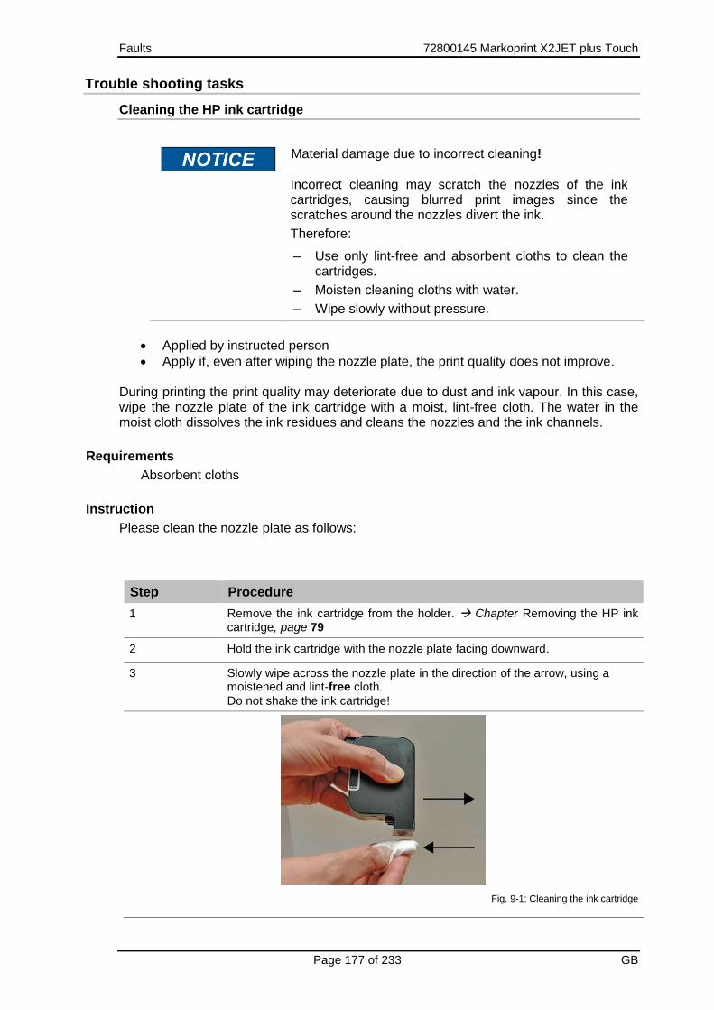
Faults 72800145 Markoprint X2JET plus Touch
Page 177 of 233 GB
Trouble shooting tasks
Cleaning the HP ink cartridge
Material damage due to incorrect cleaning!
Incorrect cleaning may scratch the nozzles of the ink cartridges, causing blurred print images since the scratches around the nozzles divert the ink.
Therefore:
– Use only lint-free and absorbent cloths to clean the cartridges.
– Moisten cleaning cloths with water.
– Wipe slowly without pressure.
Applied by instructed person
Apply if, even after wiping the nozzle plate, the print quality does not improve. During printing the print quality may deteriorate due to dust and ink vapour. In this case, wipe the nozzle plate of the ink cartridge with a moist, lint-free cloth. The water in the moist cloth dissolves the ink residues and cleans the nozzles and the ink channels.
Requirements
Absorbent cloths
Instruction
Please clean the nozzle plate as follows:
Step Procedure
1 Remove the ink cartridge from the holder. Chapter Removing the HP ink cartridge, page 79
2 Hold the ink cartridge with the nozzle plate facing downward.
3 Slowly wipe across the nozzle plate in the direction of the arrow, using a moistened and lint-free cloth. Do not shake the ink cartridge!
Fig. 9-1: Cleaning the ink cartridge

Faults 72800145 Markoprint X2JET plus Touch
Page 178 of 233 GB
Step Procedure
4 Re-insert the ink cartridge in the holder. Chapter Inserting the HP ink cartridge, page 77
A small amount of water may mix with the ink in the channels, rendering the first print a bit grey.

Faults 72800145 Markoprint X2JET plus Touch
Page 179 of 233 GB
Rinsing and de-aerate the HP ink cartridge with the ink activator
Material damage due to ink leavings!
Please secure the environment against ink leavings by removing the cartridge or take off the injection.
Therefore:
– Absorb the excess ink with an absorbent cloth.
Applied by instructed person.
Apply if, even after wiping the nozzle plate, the print quality does not improve. Ink cartridges exposed for an extended period may dry up to such an extent that simple cleaning by wiping is inadequate. Open ink cartridges subjected to severe shock or shaking may result in air entering the nozzles. These results in increased nozzle failures during printing or the ink cartridges stop printing altogether. In this case, the cartridge nozzles can be rinsed with the ink activator. The ink activator consists of a holder and an injection.
Requirements
Ink-Activator
Injection
Instruction
Please de-aerate the ink cartridge as follows:
Step Procedure
1 Insert the ink cartridge in the ink activator holder as shown in the figure.
2 Press the ink cartridge in the direction of the arrow until the cartridge is firmly seated in the holder.
Fig. 9-2: Inserting ink cartridge in den Ink-Activator
4 Insert the injection in the opening of the holder.

Faults 72800145 Markoprint X2JET plus Touch
Page 180 of 233 GB
Step Procedure
Fig. 9-3: Extracting ink
5 Slowly and steadily extract approx. 1 to 2 ml of ink from the cartridge. In case of foam formation in the injection, continue extraction until the ink appears in the injection.
6 Remove the syringe from the holder.
7 Remove the ink cartridge from the holder.
8 Wipe the nozzle plate of the ink cartridge. Chapter Cleaning the HP ink cartridge, page 177
9 Check if ink is flowing out of the nozzles.
10 If no ink is flowing, re-use the cartridge.
Air in the cartridge
Air in the cartridge makes noticeable loss nozzles. This covers an ever wider area. Air into the nozzle can occur if the cartridges be left open for long, especially when MIBL2, as these contain alcohol. Or when a cartridge is dropped, severely shaken, or is exposed to strong vibrations. To remove the air from the nozzles, the ink activator can be used as described in the manual. A typical failure screen looks like this:
Fig. 9-4: Example of a print image with loss of nozzles

Faults 72800145 Markoprint X2JET plus Touch
Page 181 of 233 GB
Cleaning the LX ink cartridge
For cleaning the LX ink cartridges please have a look to chapte „Cleaning the HP-ink cartridge“ and do it in the same way. Chapter Cleaning the HP ink cartridge, page 177 Rinsing and bleeding the MX print head
Material damage due to ink leavings!
Rinsing of the MX-Top print head results increased ink consumption and can lead to undesirable contamination of the environment.
Therefore:
– Secure the environment against leaking ink.
– Afterwards wipe the nozzle plate once with a lint-free cloth
Rinsing: There are no moving parts in the print head requiring regular maintenance. However, for printing onto outer packaging (e.g. cartons, trays, sacks, etc.) it must be expected that dust and fibre particles carried along are freed and adhere to the nozzle plate of the print head. Over a period of time, this can lead to a worsening of the print quality.
Instruction
Please rinse the MX print head as follows:
Step Procedure
1 Press the [PURGE] button on the system flange plate.
With a short push on the button it happen a flush run, the vacuum pump of the maintenance station runs to suck off the ink rests. The vacuum pump runs after ca. 1 sec. shortly to rinse ink, air and dust from the nozzles, afterwards the vacuum pump runs ca. 10 sec. to suck off the ink rests completely.

Faults 72800145 Markoprint X2JET plus Touch
Page 182 of 233 GB
Bleeding:
Instruction
Please bleed the MX print head as follows:
Step Procedure
1 Switch the system on.
Fig. 9-5: Switch the system on
2 Put the locking clamp on the nozzle plate.
Fig. 9-6: Put the locking clamp on
4 Press the [PURGE]-button and hold them pressed for ca. 30 seconds. ATTENTION, ink may leak out of the nozzle plate of the print head.
Fig. 9-7: Purge the nozzles
5 Remove the locking clamp from the nozzle plate and store it in a convenient place.

Faults 72800145 Markoprint X2JET plus Touch
Page 183 of 233 GB
Step Procedure
Fig. 9-8: Remove the locking clamp
If the button will be pressed more than 20 seconds, the vacuum pump runs continuously to de-aerate the print head. Therefore the nozzle plate should be closed with the head clamp to rinse the ink in a circulation. The pump stops pumping after 30 sec. automatically. If the contamination is too stubborn and cannot be removed by the rinsing procedure, return the unit to our factory for expert cleaning. Please note that this constitutes a service which entails costs, even during the warranty period. If the normal unit environment is constantly subject to large dust accumulation, we recommend having the unit cleaned at the factory in regular intervals of once or twice per year.

Disassembly 72800145 Markoprint X2JET plus Touch
Page 184 of 233 GB
10. Disassembly When end of the useful life expires, the system must be disassembled and disposed in an environmentally-friendly manner.
Safety
Staff
Danger to life through electric shock!
DANGER TO LIFE!
Contact with live parts poses imminent danger to life. Damaged insulation or individual components can be lethal.
Therefore:
– Immediately switch off the power supply and initiate repairs if the insulation is damaged.
– Work on the electrical system may only be performed by electricians.
– Before working on the electrical system, disconnect from the mains (remove mains plug) and check that power is off.
– Always disconnect mains before performing cleaning and repair tasks.
– Keep moisture from live parts. Moisture may cause a short-circuit.
Risk of injury caused by improper disassembly!
WARNING!
Stored residual energy, sharp-edged components, points and corners on and inside the apparatus or on the required tools may cause injuries.
Therefore:
– Ensure adequate space before starting any work.
– Handle exposed sharp-edged components with care.
– Keep the work area clean and tidy! Loosely stacked or scattered components and tools are potential causes of accidents.
– Secure components to prevent falling down or falling over.
– Consult the manufacturer if uncertain.

Disassembly 72800145 Markoprint X2JET plus Touch
Page 185 of 233 GB
Disassembly may only be performed by specially trained specialized staff.
Work on the electrical system may only be performed by electricians.
Disassembly of a MX print head
Material damage due to incorrect disposal!
Electronic components are destroyed if allowed to come into contact with escaping ink.
Therefore:
– Close the ink systems before disposal carefully.
Instruction
Please disassemble the MX print head as follows:
Step Procedure
1 Switch off the control system.
2 Isolate maintenance station or main adaptor from the print head.
3 Close the print head with the cleaned locking clamp.
4 Remove the ink bottle.
5 Check whether the red sealing ring (o-ring) is present.
6 Place the red sealing ring into the opening of the ink container and close it with the screw cap.
7 Close ventilation opening with the plastic cap.
8 Disassemble the system and pack it carefully.
To prevent damage during transportation, choose a box with adequate padding. Leave a gap of at least 5cm between unit and box for filling with absorbent and impact-absorbing filling. Please do not pack unit in plastic bag. Because any escaped ink cannot be soaked up, it spreads over the whole unit causing damage. The resulting damage and cleaning overhead unnecessarily increase repair costs. For best possible transportation, original packaging is available from Weber Marking Systems for this system.

Disassembly 72800145 Markoprint X2JET plus Touch
Page 186 of 233 GB
Disposal
Environmental damage due to incorrect disposal!
Electrical scrap, electronic components, lubricants and other auxiliary materials are subject to hazardous waste treatment regulations and may only be disposed of by approved specialized companies!
Unless return or disposal agreements were made, submit disassembled components for recycling:
Scrap metals.
Submit plastic components for recycling.
Dispose of other components according to material composition. The local municipal authorities or specialized disposal companies provide information on environmentally compatible disposal.

List of Accessories and Spare parts 72800145 Markoprint X2JET plus Touch
Page 187 of 233 GB
11. List of Accessories and Spare parts
Safety hazard due to incorrect spare parts!
Incorrect or faulty spare parts may affect safety and cause damage, malfunctions or failure.
Therefore:
– Only use original spare parts from the manufacturer.
Procure spare parts via contracted dealers or directly from the manufacturer.
HP ink cartridges
Material damage can be caused by spraying ink!
Spitting results in increased ink consumption and can lead to undesirable contamination of the environment.
Therefore:
– Hold an absorbent cloth in front of the nozzle plate of the ink cartridge.
The specified drying times can be reduced by additional heat treatment (hot-air blower, IR heater). The open time can be extended by spit pulse programming. Please note the ink specific settings for head voltage, fire time, spitting and warming. There is the possibility to set up the ideally standard values for the respective ink type on the iDesign software or Web interface. It makes sense to change the values carefully depending on the application. After the insertion of a new cartridge the ink counter must be reset and the temperature measurement must be calibrated. Ink level: Chapter Reset ink counter, page 159 Temperature: Chapter Warming, page 161 The settings can be made with the iDesign software below Functions / System settings / Advanced settings.

List of Accessories and Spare parts 72800145 Markoprint X2JET plus Touch
Page 188 of 233 GB
Pos. Name Description Art.no
1 HP-Set 4 STABL 2 x ink cartridges, color black, volume per cartridge 42 ml. Specially developed, highly pigmented HP ink. Well suited for sharp edged print on absorbent materials. Drying: Good on absorbent surfaces; ink does not dry on poorly absorbent surfaces since the pigments remain on the surface. Open time without loss of quality: Approx. 15 minutes (depending on print resolution and print image).
72500013
2 HP Set 12 UVINV
2x print cartridges, colour transparent, volume each 42 ml. Specially developed HP ink, readable under UV light. Well suited for sharp edged print on poorly absorbent materials.
72500021
3 HP Set 14 MIBL 2
2x print cartridges, colour black, volume each 42 ml. Specially developed, solvent-containing, pigmented HP ink. Well suited for sharp edged print on lacquered materials.
72500023
4 HP Set 26 RCBLU
2x print cartridges, colour blue, content per 42 ml. Specially developed, solvent-containing HP ink. Well suited for printing on poorly absorbent material. Drying: On poorly absorbent surfaces within a few seconds, on absorbent surfaces immediately. Good marginal sharpness on poorly absorbent surfaces. Open time without loss of quality: Up to 2 hours (depending on intensity and print image).
72500036
5 HP Set 27 RCRD 2x print cartridges, colour red, content per 42 ml. Specially developed, solvent-containing HP ink. Well suited for printing on poorly absorbent material.
72500037
6 Cartridge HP WDGN1
1x print cartridge, colour green, content per 42 ml. Specially developed, solvent-containing HP ink. Well suited for printing on poorly absorbent material.
40013323
7 Cartridge HP Ultra Black
1x print cartridge, colour black, content per 42 ml. Specially developed, non-pigmented dye-based ink. Well suited for pin sharp prints on absorbent and semi-absorbent materials. Delivered as SmartCard cartridge.
40018776
8 Cartridge HP 2580
1x print cartridge, colour black, content per 35 ml. Specially developed, dye-based ink (solvent based). Good adhesion qualities on different non-absorbent surfaces. Long open time (approx. 900 minutes) Delivered as SmartCard cartridge.
40012279
9 Cartridge HP SDBLK3
1x print cartridge, colour black, content per 35 ml. Specially developed, dye-based ink (solvent based). High blackness, abrasion-resistant on some non-absorbent surfaces. Delivered as SmartCard cartridge.
40017072
10 Cartridge HP WDBLK1
1x print cartridge, colour black, content per 42 ml. Specially developed, non-pigmented dye-based ink. Well suited for printing on absorbent and semi-absorbent surfaces. Delivered as SmartCard cartridge.
40010705
11 Cartridge HP WDBLK2
1x print cartridge, colour black, content per 42 ml. Specially developed, non-pigmented dye-based ink. Well suited for printing on absorbent and semi-absorbent surfaces. Open time: up to 4 hours without loss of quality. Delivered as SmartCard cartridge.
40016702

List of Accessories and Spare parts 72800145 Markoprint X2JET plus Touch
Page 189 of 233 GB
Pos. Name Description Art.no
12 HP Pack STABL 10x print cartridges, colour black, content per 42 ml. Specially developed, solvent-containing HP ink. Well suited for printing on poorly absorbent material. Delivered as SmartCard cartridge.
72500139

List of Accessories and Spare parts 72800145 Markoprint X2JET plus Touch
Page 190 of 233 GB
LX ink cartridges
No. Name Description Art.no
1 LX GP+
Ink cartridge, modified, color black, 33 ml capacity each. Specially developed, high pigmented, water-based Funai ink. Well suited for sharp edged print on poorly absorbent materials. Drying: Immediate drying on absorbent surfaces, no drying on poorly absorbent surfaces, because the pigments remain on the surface. Open time without loss of quality: Approx. 15 minutes (depending on intensity and print image).
72500301
2 LX GP1 Ink cartridge, modified, color black, 33 ml capacity each. Specially developed, high pigmented, water-based Funai ink. Well suited for sharp edged print on poorly absorbent materials. Drying: Immediate drying on absorbent surfaces, no drying on poorly absorbent surfaces, because the pigments remain on the surface. Open time without loss of quality: Approx. 30 minutes (depending on intensity and print image).
40006208
3 LX SD1 Ink cartridge, modified, color black, 33 ml capacity each. Specially developed, high pigmented, water-based Funai ink.
72500306
4 LX RD1 Ink cartridge, modified, color black, 33 ml capacity each. Specially developed dye-, water-based Funai ink.
72500317
5 LX NP1 Ink cartridge, modified, color black, 33 ml capacity each. Specially developed solvent-based ink of Funai. Well suited for prints on semi-absorbent and non-absorbent materials, depending on the intensity. Open time without loss of quality: Up to 8 hours.
40009494

List of Accessories and Spare parts 72800145 Markoprint X2JET plus Touch
Page 191 of 233 GB
Mounting brackets
No. Figure Article Description Order no.
1
Mounting bracket controller MX print head
For a fixing on a conveyor from the side.
71800027
2
Mounting bracket HP print head
For a fixing on a conveyor from the side, with quick fastener to take the head out of the mounting bracket without technical tools. Model „Dovetail“
72801010
3
Mounting bracket HP print head TOP
For a fixing on a conveyor from the top, with quick fastener to take the head out of the mounting bracket without technical tools. Model „Dovetail“
72801011
4
Mounting bracket MX print head TOP
For a fixing on a conveyor from the top.
71800029
5
Floor stand for 1 or 2 print heads
For a fixing on a conveyor from the top.
71800034

List of Accessories and Spare parts 72800145 Markoprint X2JET plus Touch
Page 192 of 233 GB
Other
No. Figure Subassembly Description Order no.
1
PE sensor NPN, 10…30V DC Standard M18
including 5.0 m connecting and adapter cable (M12 to M8) and universal holder
72801012
2
PE sensor NPN, 10…30V DC M8
including 0.6 m connecting cable and VA holder, for direct mounting of the print head from the side
72801013
3
PE sensor NPN, 10…30V DC, external 32x15mm
for mounting behind the front panel, including 0.6 m connecting cable
72801014
4
PE sensor (NPN), 10-30V DC, X2JET/X4JET MX
Inkl. 5,0m Anschlusskabel (M8 auf M8) zur direkten, seitlichen Montage am MX Druckkopf
72801074
5
PE sensor (NPN), 10-30V DC, X2JET/X4JET mit MX 50 Abweiser
Inkl. 5,0m Anschlusskabel (M8 auf M8) zur seitlichen Montage am MX 50 Druckkopf
72801077
6
PE sensor (NPN), 10-30V DC, X2JET/X4JET mit MX 100 Abweiser
Inkl. 5,0m Anschlusskabel (M8 auf M8) zur seitlichen Montage am MX 100 Druckkopf
72801079
7
Rotary encoder (600dpi) Spring arm holder
Rotary encoder with spring arm and aluminium friction wheel (600dpi), including connecting and adapter cable (M12 to M8)
72801018
8
Rotary encoder Spring arm holder
Rotary encoder with spring arm and plastic friction wheel, including connecting and adapter cable (M12 to M8)
72801015

List of Accessories and Spare parts 72800145 Markoprint X2JET plus Touch
Page 193 of 233 GB
No. Figure Subassembly Description Order no.
9
Rotary encoder (600dpi) Angle holder
Rotary encoder with angle holder and aluminium friction wheel (600dpi), including connecting and adapter cable (M12 to M8)
72801019
10
Rotary encoder Angle holder
Rotary encoder with angle holder and plastic friction wheel, including connecting and adapter cable (M12 to M8)
72801016
11
USB-data-stick Version 1 72901202
12 CartClip for retaining ink cartridges type 15/45
72900074
13 Ink-Aktivator for de-aerating and cleaning the ink cartridges
72900108
14 CartClip for retaining LX ink cartridges 72902026
15
Measuring wheel Measuring wheel for encoder, optimized for 600 dpi
72900454
16
O-Ring O-ring for encoder measuring wheel (600 dpi) Dimensions: 55x5; NBR
72900455
17
Alarm light „Alarm light“ (red/yellow/green) for an optical display of the operation
22702287
18 Cable Connecting cable 1m 72900225
19 Cable Connecting cable 3m Standard accessories with every print head
72900053
20 Cable Connecting cable 5m 72900085
21 Cable Connecting cable 10m 72900226
22 Cable Connecting cable 25m 72900228
23 Cable Extension cable 5m 72900086

List of Accessories and Spare parts 72800145 Markoprint X2JET plus Touch
Page 194 of 233 GB
No. Figure Subassembly Description Order no.
24 Cable Extension cable 10m 72900227
25 Cable Adapter M8 connector to M12 socket 0,6m
72901035
26
Cleaning stick
Cleaning stick to clean the nozzle plate
40007189

Appendix 72800145 Markoprint X2JET plus Touch
Page 195 of 233 GB
12. Appendix
Ink chart
The Markoprint X2JET plus Touch contains ink tables for the different print systems. The optimal value of an ink will be automatically adopted by the ink selection. If the parameters were changed in the iDesign software, the changed parameters stay active till a new ink type will be select on the Markoprint X2JET plus Touch. The ink tables are stored as excel tables in the HMI account: „InkPar.csv“. The chart can be adapted customized with a Software-Update Chapter Software-Update, page 197 and can transferred to the Markoprint X2JET plus Touch memory. Changes of the ink parameter can cause bad print images and should change from qualified persons only.
„InkPar.csv“ (for HP systems):

Appendix 72800145 Markoprint X2JET plus Touch
Page 196 of 233 GB
„InkParLX.csv“ (for LX-Systems):
„InkParMX.csv“ (for MX-Systems):

Appendix 72800145 Markoprint X2JET plus Touch
Page 197 of 233 GB
Software-Update
Software update with USB-Stick
Requirements
Following folder must be copied to an empty USB-Stick: HMI, HMI+, HTML and System.
The Markoprint X2JET plus Touch is off.
Instruction
Please proceed a software update with USB-stick as follows:
Step Procedure
1 Make sure that the Markoprint X2JET plus Touch control system is off.
2 Insert the USB stick with the new version in the lateral USB socket.
3 Switch on system and when the start logo appears (Bluhm/Weber, Markoprint X2JET plus Touch) keep the INFO button pushed.
4 The following then appears on the display: Prg: 0 PV1.0xx new Program Version GA.: 0GV0.032 new Gate Array Version Copy to SD?
5 By briefly pressing the OK button the new version is copied to the internal SD card and the system restarts.
6 Now remove the USB-Stick.
Software-Upgrade
A software upgrade with costs is comfortably possible via the Weber Marking Partner Portal. Please contact your consultant or local distributor to get an software-upgrade. You can find a detailed instruction of the software upgrade below the search key „Configuration upgrade“ in the Wiki of the Weber Marking Partner Portal.
Appendix 72800145 Markoprint X2JET plus Touch
Page 198 of 233 GB
HMI-Update
A HMI-Update of the system unit will be realized with a new software version automatically and must be confirmed by the OK button. A HMI-Update without software update is realized as follows:
Requirements
A USB-stick with the new HMI-data is available.
The Markoprint X2JET plus Touch is off.
Instruction
Please proceed a HMI-Update without a software update as follows:
Step Procedure
1 Make sure that the Markoprint X2JET plus Touch control system is off.
Insert the USB stick with the new version in the lateral USB socket.
2 Switch the system on and keep the OK button pressed by appearance of the program version.
3 On the display is shown: Copy HMI-Data from Stick?
4 Confirm by touching the OK button.
5 Wait till “ready“
6 Start the system with a short pressure at the OK button.
7 Now remove the USB-Stick.
Bootloader-Update
The system may under no circumstances be switched off during the boot loader update. If the update cannot be completed, do not restart the system. To replace the boot loader the system must then be send to the manufacturer.
Requirements
A USB-stick with the new Bootloader version is needed. The USB-stick includes the program folder „SYSTEM““.
The Markoprint X2JET plus Touch is off.
Instruction
Please proceed a Bootloader-Update as follows:
Step Procedure
1 Make sure that the Markoprint X2JET plus Touch control system is off.
2 Switch on system and when the start logo appears (Bluhm/Weber, Markoprint X2JET plus Touch) keep the INFO button pushed.

Appendix 72800145 Markoprint X2JET plus Touch
Page 199 of 233 GB
Step Procedure
3 The following then appears on the screen: Prg: 0 PV1.0xx actual program version GA.: 0GV0.032 actual Gate Array version Stick?
4 Insert the USB stick with the new version in the lateral USB socket.
5 The following then appears on the screen: Prg: 0 PV1.0xx new Program version GA.: 0GV0.032 new Gate Array version Start?
6 By briefly pressing the OK button the new boot loader version is copied to the internal memory.
7 The green power LED lights up during the copying process.
8 Wait until the end of the copying process, with the power LED lit up and the sensor LED displayed in green!
9 Restart the system by switching off the voltage and switching on again.
The system may under no circumstances be switched off during the boot loader update. If the update cannot be completed, do not restart the system. To replace the boot loader the system must then be send to the manufacturer.

Appendix 72800145 Markoprint X2JET plus Touch
Page 200 of 233 GB
Date variables
Acceptation of the specific variable letters:
Variable Meaning
a Day, tens
b Day, units
c Month, tens
d Month, ones
e Year, thousands
f Year, hundreds
g Year, tens
h Year, ones
i Hour, tens
j Hour, ones
k Minute, tens
l Minute, ones
m Second, tens
n Second, ones
ooo Month, as string
ppp Day of the year
Q Weekday
rr Calendar week
s Hour as character (0=A, 1=B, …, 23=Z)
t Shift code (max. 4 digits)
u Day of the year, hundreds
v Day of the year, tens
w Day of the year, ones
A Day, ones (zero suppression)
B Day as character
(1-9=A, 10-19=B, 20-29=C, ...)
C Month, tens (zero suppression)
D Month as character
(1=A, 2=B, …, 12=M)
G Year, tens (zero suppression)
H Year, units as character (0=C, 1=M, 2=E, 3=A, 4=D,
5=J, 6=O, 7=H, 8=N, 9=S)
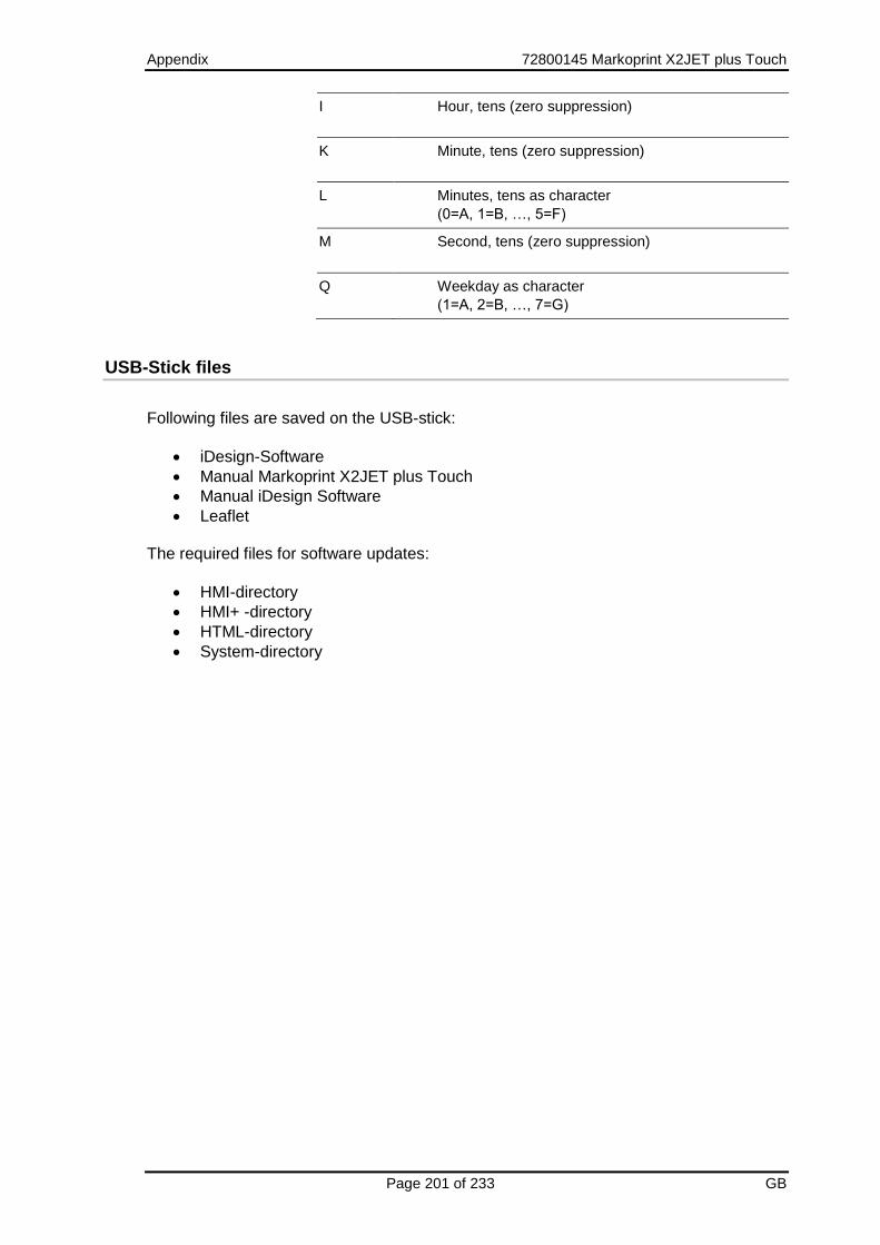
Appendix 72800145 Markoprint X2JET plus Touch
Page 201 of 233 GB
I Hour, tens (zero suppression)
K Minute, tens (zero suppression)
L Minutes, tens as character
(0=A, 1=B, …, 5=F)
M Second, tens (zero suppression)
Q Weekday as character
(1=A, 2=B, …, 7=G)
USB-Stick files
Following files are saved on the USB-stick:
iDesign-Software
Manual Markoprint X2JET plus Touch
Manual iDesign Software
Leaflet The required files for software updates:
HMI-directory
HMI+ -directory
HTML-directory
System-directory

Appendix 72800145 Markoprint X2JET plus Touch
Page 202 of 233 GB
Boot-error messages
If an error number is displayed during booting of the system, this can be limited by means of the following list.
Boot-Error Description
01 General hardware error
02 Memory error
03 Timer error
04 SPI / Bluetooth error
05 Gate Array error
06 Display error
07 SD Card error
08 USB-A error
09 Real time clock error
10 Multitasking-error
Main Error Description
01 General hardware error
02 Memory error
03 Timer error
04 SPI / Bluetooth error
05 Gate Array error
06 Display error
07 SD Card error
08 USB-A error
09 Real time clock error
10 Multitasking error
11 Ethernet error
12 USB-B error
13 HP head error
14 Control error
15 NV-RAM error
MInit-Error Description
01 File device error
02 File system error
03 Parameter error
04 User Call error
05 TCP-IP error
06 Print control error
Init-Error Description
01 File device error
02 File system error
03 User call error
SW-configuration error
Description
-1 Invalid data
-2 Wrong check sum
-3 Wrong Header-ID
-4 Unknown HW-Revision
-5 Unknown MOP-serial number
-6 Wrong MAC-address

Appendix 72800145 Markoprint X2JET plus Touch
Page 203 of 233 GB
Boot-LED messages
During booting of the system progress can be determined by means of the LED. If the system stops during booting the cause can be determined by means of the LED. FC means flashing. An error can be determined on the basis of the number of flashes.
Status-LED
Sensor-LED
Description
ye ye Write 64MB memory
rd — Read/ invert 64MB memory
— rd Read/ test 64MB memory
ye — Test ok / Load BootMain from SPI
— ye Programming and start of BootMain
ye rd BootMain initialization
— — Fatal error
rd rd Boot error 4x = SPI; 5x = GA; 6x = Displ; 7x = SD-Card; 8x = USB; 9x = RTC; 10x = Task
rd FC: rd Init error 1x = Dev; 2x = FS; 3x= UsrCl
rd FC: gn SD card read
ye gn Wait for stick
ye rd / gn No boot data
ye rd / — Write 64MB memory
ye ye / gn Booting from stick?
ye ye / rd Copy from stick?
ye gn / — Copy Ok
gn — Main program loaded and started

Appendix 72800145 Markoprint X2JET plus Touch
Page 204 of 233 GB
Plug connection
Sensor
Sensor input: 24V Standard: NPN (switching to GND)
Can be changed to PNP via software. Photocell with 4-pole M8 round plug
PIN Description Value Unit
1 Power + 24 V
2 – Sen2 Start pulse (inverted signal) Input standard NPN -
3 GND 0 V
4 – Sen1 Start pulse Input standard NPN -
The PIN2 can optionally be used as an additional input. This must be programmed customer-specifically. Standard is the inverse output by many sensors. The input can selected as sensor 1+2 inverted in the menu. Signal threshold 12V +- 2V Encoder
Encoder input: 24V Standard: NPN or push-pull max. 100kHz Rotary encoder with 4-pole M8 round plug
PIN Description Value Uniit
1 Power, max. 10mA + 24 V
2
3 GND 0 V
4 Encoder signal Standard: NPN or push-pull
-
Fig. 12-1: Socket 4-pole M8 plug
PIN 1 BN (brown)
PIN 2 WH (white) PIN 4 BK (black)
PIN 3 BU (blue)
View on plug back side

Appendix 72800145 Markoprint X2JET plus Touch
Page 205 of 233 GB
PIN Cable colour
1 Brown 24V
2 White input
3 Blue 0V (ground)
6 Black input
When using the splitter cable are both inputs / outputs clearly separated. The input Pin2 is on a connection on Pin4 (see Fig.12-1).
Fig. 12-2: Splitter cable and whose pin assignment

Appendix 72800145 Markoprint X2JET plus Touch
Page 206 of 233 GB
Alarm light
The alarm light (24V) will be connected to the 8-pole M12-socket. 24V voltage will be switched on the outputs.
PIN Color Function
1 – Out1 White Alarm red lamp
2 – Out2 Brown Warning orange lamp
3 – Out3 Green OK green lamp
4 – Out4 Yellow Reserve
5 – In 7 Reserve
6 – In 8 Reserve
7 - +24V Power max. 100mA
8 - GND Red common contact

Appendix 72800145 Markoprint X2JET plus Touch
Page 207 of 233 GB
External Output
The outputs are potential-free. The relay is designed for 24V. Relay output: max 24 V and max. 100 mA. Standard: Closing contact.
Connection 15-pole Sub-D-socket.
Input NPN input, can be changed to PNP via software.
Standard NPN (to GND switching)
Input voltage for PNP 10 V…24 V
PIN Name Description Potential
1 GND Power 0V
2 RS232 RXD
3 RS232 TXD
4 In User 4 Standard: NPN
5 In User 5 Standard: NPN
6 In User 6 Standard: NPN
7 RS232 GND
8 Encoder channel 2 In Standard: push pull
9 In User 3 Standard: NPN
10 Encoder channel 1 In Standard: push pull
11 Start Channel 1 Input 1 Standard: NPN
12 In User 2 Standard: NPN
13 In User 1 Standard: NPN
14 Out 6 Warning Relais max. 24V / 100mA
15 Out 5 OK Relais max. 24V / 100mA
16 Out 7 ALARM Relais max. 24V / 100mA
17 Common Relais
18 Out 8 User Relais max. 24V / 100mA
19 Start channel 2 / inv. Input 4 Standard: NPN
20 Start channel 2 Input 3 Standard: NPN
21 Out 1 User 24V / max.100mA
22 Out 2 User 24V / max.100mA
23 Out 3 User 24V / max.100mA
24 Out 4 User 24V / max.100mA
25 Vpp Power +24V

Appendix 72800145 Markoprint X2JET plus Touch
Page 208 of 233 GB
Splitter cable for 2channel head Art. no.: 72900451 25 pin Sub-D-plug 9pin Sub-D-plug (RS232) PIN 2 ------------------------------------------------PIN 2 PIN 3 ------------------------------------------------PIN 3 PIN 7 ------------------------------------------------PIN 5 25 pin Sub-D-plug 3pin M12 socket (Encoder) PIN 1 ------------------------------------------------PIN 3 PIN 8 ------------------------------------------------PIN 4 PIN 25 ----------------------------------------------PIN 1 25 pin Sub-D-plug 3pin DIN socket (Sensor) PIN 1 ------------------------------------------------PIN 3 PIN 19 ----------------------------------------------PIN 2 PIN 20 ----------------------------------------------PIN 4 PIN 25 ----------------------------------------------PIN 1 25 pin Sub-D-plug 8pin M12 socket (alarm light) PIN 1 ------------------------------------------------PIN 8 PIN 14 ----------------------------------------------PIN 2 PIN 15 ----------------------------------------------PIN 3 PIN 16 ----------------------------------------------PIN 1 PIN 17 --- connect to PIN 25 PIN 25 --- connect to PIN 17

Appendix 72800145 Markoprint X2JET plus Touch
Page 209 of 233 GB
In- and Output

Appendix 72800145 Markoprint X2JET plus Touch
Page 210 of 233 GB
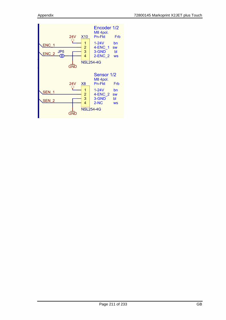
Appendix 72800145 Markoprint X2JET plus Touch
Page 211 of 233 GB

Appendix 72800145 Markoprint X2JET plus Touch
Page 212 of 233 GB
Print head cable
Configuration of the 24+4+1 HP print head cable
PIN Name Description Level
1 DOUT- out Lvds
2 DOUT+ out Lvds
3 AGND power 0 V
4 DIN_1- in Lvds
5 DIN_1+ in Lvds
6 PWHFIRE- in Lvds
7 PWHFIRE+ in Lvds
8 IR_Signal out 0 V
9 DIN_2- in Lvds
10 DIN_2+ in Lvds
11 AGND power 0 V
12 DCLK- in Lvds
13 DCLK+ in Lvds
14 VCC power 5 V
15 GND power 0 V
16 res power 0 V
17 DLOAD- in Lvds
18 DLOAD+ in Lvds
19 AGND power 0 V
20 HCLK- in Lvds
21 HCLK+ in Lvds
22 AGND power 0 V
23 HFIRE- in Lvds
24 HFIRE+ in Lvds
C1 VPP power 24 V
C2 VPP power 24 V
C3 VPF power 30 V
C4 VPF power 30 V
C5 GND power 0 V

Appendix 72800145 Markoprint X2JET plus Touch
Page 213 of 233 GB
USB A / B
The USB sockets are standard sockets, as used in commercial PCs and USB devices. Insert the USB plug vertically into the USB socket without using force.
PIN Name Color Description
1 VCC Red +5 V
2 D- White Data -
3 D+ Green Data +
4 GND Black Mass
Ethernet
Network input RJ 45 on the system back.
PIN Description
1 Transmit+
2 Transmit-
3 Receive+
6 Receive-
MAC addresses
The MAC address of the respective Markoprint X2JET plus Touch can be seen on the system directly.
Range from: To:
00-50-C2-A6-50-00 00-50-C2-A6-5F-FF

Appendix 72800145 Markoprint X2JET plus Touch
Page 214 of 233 GB
Technical drawings
Control system Markoprint X2JET plus Touch
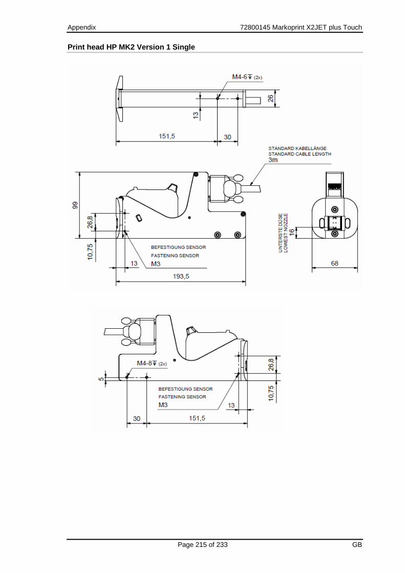
Appendix 72800145 Markoprint X2JET plus Touch
Page 215 of 233 GB
Print head HP MK2 Version 1 Single

Appendix 72800145 Markoprint X2JET plus Touch
Page 216 of 233 GB
Print head HP MK2 Version 2 Single
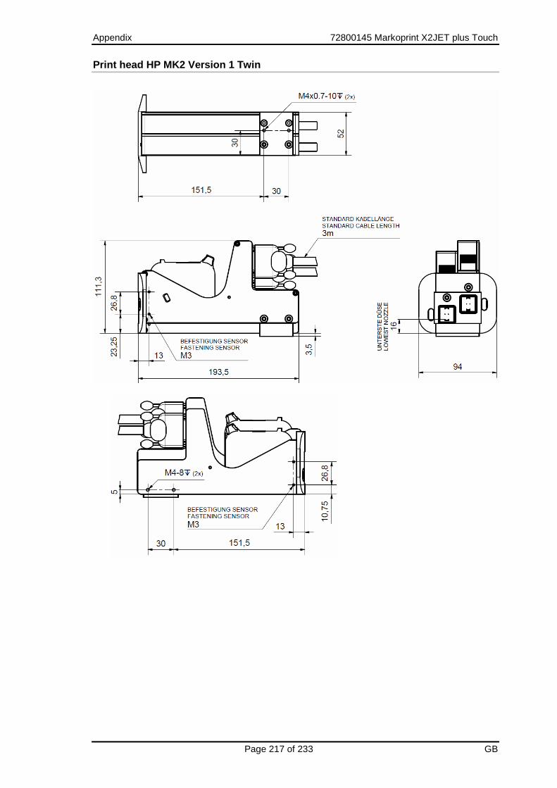
Appendix 72800145 Markoprint X2JET plus Touch
Page 217 of 233 GB
Print head HP MK2 Version 1 Twin

Appendix 72800145 Markoprint X2JET plus Touch
Page 218 of 233 GB
Print head HP MK2 Version 2 Twin

Appendix 72800145 Markoprint X2JET plus Touch
Page 219 of 233 GB
Print head LX MK2 Version 1

Appendix 72800145 Markoprint X2JET plus Touch
Page 220 of 233 GB
Print head LX MK2 Version 2

Appendix 72800145 Markoprint X2JET plus Touch
Page 221 of 233 GB
Druckkopf LX MK2 Version 1 Twin

Appendix 72800145 Markoprint X2JET plus Touch
Page 222 of 233 GB
Druckkopf LX MK2 Version 2 Twin
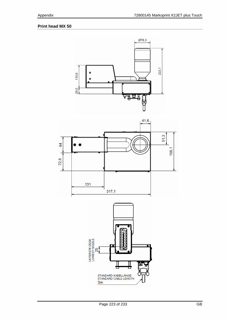
Appendix 72800145 Markoprint X2JET plus Touch
Page 223 of 233 GB
Print head MX 50

Appendix 72800145 Markoprint X2JET plus Touch
Page 224 of 233 GB
Print head MX 100

Appendix 72800145 Markoprint X2JET plus Touch
Page 225 of 233 GB
Mounting bracket Compact

Appendix 72800145 Markoprint X2JET plus Touch
Page 226 of 233 GB
Mounting bracket Top

Appendix 72800145 Markoprint X2JET plus Touch
Page 227 of 233 GB
Universal mounting bracket for control system and MX-print head
These pictured drawings show an extraction of the possible variations of the print heads. Further drawings or 3D-CAD data can be required by the manufacturer

Appendix 72800145 Markoprint X2JET plus Touch
Page 228 of 233 GB
Instruction sheet
Copy the instruction sheet before completing.
Date Name Type of instruction Instruction by Signature

Appendix 72800145 Markoprint X2JET plus Touch
Page 229 of 233 GB
Parameter list
Parameter After Reset Min. Max. Actual value
Unit
Pulse Internal Head2 from head 1
Speed 15,0 1,0 400 m/min
Encoder 600 50 5000 ppi
Print direction
RL LR RL
Upside down
No No Yes
Reflect Not used
Print delay 25 0 999 mm
Print repeat distance
0 0 9999 mm
Number of print repeats:
0 0 999
Intensity 50 300 900 DPI
Print width 100 10 900 %
Nozzle rows A~B A,B A+B
Head voltage
110 V
Fire time 190 0,01µs
Fire pause 190 0,01µs
Barcode correction
0 Pixel
Ink warning 5 0 100 %
Spitting mode
OFF BEFORE INTERVALL
Number of spit ripping
20 0 100
Spit delay 10 0 999 s
Spit interval 600 0 999 s
Auto Off 60 0 999 min.
Head correction
0 -50 +50 Pixel
Offset bi directional
0 -20 +20
Warming OFF OFF ON
Warming Temp.
45 20 80 °C

Appendix 72800145 Markoprint X2JET plus Touch
Page 230 of 233 GB
Parameter After Reset Min. Max. Actual value
Unit
Warming timer
0 0 999 s
Counter start value
Not used
Language German -
Head type 1111 1000 4000
Ink type STABL -
User 1 Not used -
User 2 Not used
User 3 Not used
Print mode Not used
Save variable fields
Not used
Sensor 1+2 1+2 3+4
Turning display Not used
Sensor I/O Not used
Encoder I/O Not used
Trigger output delay
Not used
Impulse length output
Not used
HiSpeed NO YES NO
Fixed print width YES NO YES
EIA232 Not used
Polarity input 0000
Input 1,2 0000
Input 3,4 0000
Input 5,6 0000
Input 7,8 0000
Output 1,2 3020
Output 3,4 1000
Output 5,6 1020
Output 7,8 3000

Appendix 72800145 Markoprint X2JET plus Touch
Page 231 of 233 GB
The Markoprint X2JET plus Touch will be reset to the basic configuration after sending these commands.
<ESC>K1<CR> <ESC>M*;0000;0150;0004;0000;0000;0000;0025;0000;0000;0300;0100;0000;0110;0190;0190;0000;0005;0000;0020;0010;0600;0060;0000;0000;0000;0045;0000;0000;0000;1111;0001;0000;0000;0000;0000;0000;0000;0000;0000;0000;0000;0000;0000;0000;0000;0000;0000;0000;0000;0000;3020;1000;1020;3000<CR> <ESC>K2<CR> <ESC>M*;0000;0150;0004;0000;0000;0000;0025;0000;0000;0300;0100;0000;0110;0190;0190;0000;0005;0000;0020;0010;0600;0060;0000;0000;0000;0045;0000;0000;0000;1111;0001;0000;0000;0000;0000;0000;0000;0000;0000;0000;0000;0000;0000;0000;0000;0000;0000;0000;0000;0000;3020;1000;1020;3000<CR> <ESC>K3<CR> <ESC>M*;0002;0150;0004;0000;0000;0000;0025;0000;0000;0300;0100;0000;0110;0190;0190;0000;0005;0000;0020;0010;0600;0060;0000;0000;0000;0045;0000;0000;0000;1111;0001;0000;0000;0000;0000;0000;0000;0000;0000;0000;0000;0000;0000;0000;0000;0000;0000;0000;0000;0000;3020;1000;1020;3000<CR> <ESC>K4<CR> <ESC>M*;0002;0150;0004;0000;0000;0000;0025;0000;0000;0300;0100;0000;0110;0190;0190;0000;0005;0000;0020;0010;0600;0060;0000;0000;0000;0045;0000;0000;0000;1111;0001;0000;0000;0000;0000;0000;0000;0000;0000;0000;0000;0000;0000;0000;0000;0000;0000;0000;0000;0000;3020;1000;1020;3000<CR>

Appendix 72800145 Markoprint X2JET plus Touch
Page 232 of 233 GB
Declaration of Conformity
The Markoprint X2JET plus Touch corresponds to the design and construction as well as the system version with the essential safety requirements of the Low-Voltage- and EMV-Directives including whose changes for this time period.

Appendix 72800145 Markoprint X2JET plus Touch
Page 233 of 233 GB