mash 207, 312 elsarnagawy, t. chapter 2 voltage and current
TRANSCRIPT

MASH 207, 312Elsarnagawy, T.
Chapter 2
Voltage and Current

Introductory Circuit Analysis, 12/eBoylestad
Copyright ©2011 by Pearson Education, Inc.publishing as Pearson [imprint]
OBJECTIVES
• Become aware of the basic atomic structure of conductors such as copper and aluminum and understand why they are used so extensively in the field.
• Understand how the terminal voltage of a battery or any dc supply is established and how it creates a flow of charge in the system.
• Understand how current is established in a circuit and how its magnitude is affected by the charge flowing in the system and the time involved.

Introductory Circuit Analysis, 12/eBoylestad
Copyright ©2011 by Pearson Education, Inc.publishing as Pearson [imprint]
OBJECTIVES
• Become familiar with the factors that affect the terminal voltage of a battery and how long a battery will remain effective.
• Be able to apply a voltmeter and ammeter correctly to measure the voltage and current of a network.
Introductory Circuit Analysis, 12/eBoylestad
Copyright ©2011 by Pearson Education, Inc.publishing as Pearson [imprint]
INTRODUCTION
• Now that the foundation for the study of electricity/electronics has been established, the concepts of voltage and current can be investigated. – The term voltage is encountered practically every day. – We are aware that most outlets in our homes are 120
volts.
• Although current may be a less familiar term, we know what happens when we place too many appliances on the same outlet—the circuit breaker opens due to the excessive current that results.
Introductory Circuit Analysis, 12/eBoylestad
Copyright ©2011 by Pearson Education, Inc.publishing as Pearson [imprint]
ATOMS AND THEIR STRUCTURE
• A basic understanding of the fundamental concepts of current and voltage requires a degree of familiarity with the atom and its structure. – The simplest of all atoms is the hydrogen atom,
made up of two basic particles, the proton and the electron.
– The nucleus of the hydrogen atom is the proton, a positively charged particle.
• The orbiting electron carries a negative charge equal in magnitude to the positive charge of the proton.

Introductory Circuit Analysis, 12/eBoylestad
Copyright ©2011 by Pearson Education, Inc.publishing as Pearson [imprint]
ATOMS AND THEIR STRUCTURE
FIG. 2.1 Hydrogen and helium atoms.

Introductory Circuit Analysis, 12/eBoylestad
Copyright ©2011 by Pearson Education, Inc.publishing as Pearson [imprint]
ATOMS AND THEIR STRUCTURE
• Copper is the most commonly used metal in the electrical/electronics industry.
• An examination of its atomic structure will reveal why it has such widespread application.
• It has 29 electrons in orbits around the nucleus, with the 29th electron appearing all by itself in the 4th shell.

Introductory Circuit Analysis, 12/eBoylestad
Copyright ©2011 by Pearson Education, Inc.publishing as Pearson [imprint]
ATOMS AND THEIR STRUCTURE
FIG. 2.2 The atomic structure of copper.

Introductory Circuit Analysis, 12/eBoylestad
Copyright ©2011 by Pearson Education, Inc.publishing as Pearson [imprint]
VOLTAGE
• If we separate the 29th electron in Fig. 2.2 from the rest of the atomic structure of copper by a dashed line as shown in Fig. 2.4(a), we create regions that have a net positive and negative charge as shown in Fig. 2.4(b) and (c). FIG. 2.4 Defining the positive ion.

Introductory Circuit Analysis, 12/eBoylestad
Copyright ©2011 by Pearson Education, Inc.publishing as Pearson [imprint]
VOLTAGE
• This positive region created by separating the free electron from the basic atomic structure is called a positive ion.
• In general, every source of voltage is established by simply creating a separation of positive and negative charges.
Introductory Circuit Analysis, 12/eBoylestad
Copyright ©2011 by Pearson Education, Inc.publishing as Pearson [imprint]
VOLTAGE
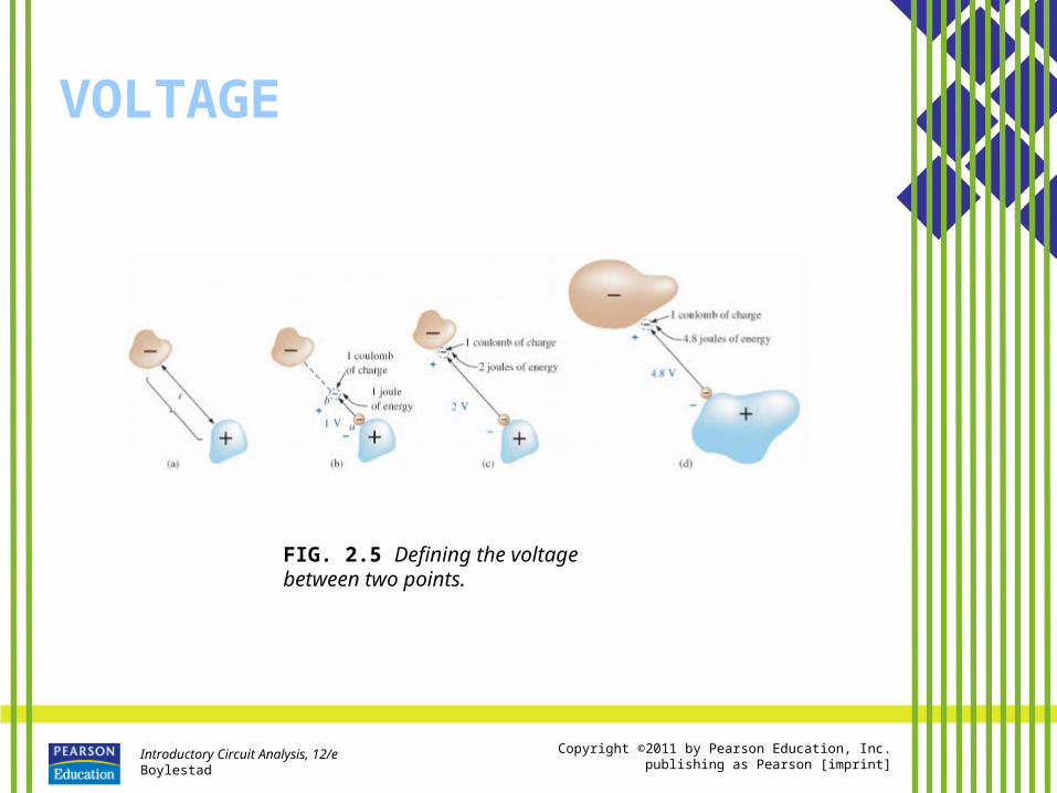
FIG. 2.5 Defining the voltage between two points.
Introductory Circuit Analysis, 12/eBoylestad
Copyright ©2011 by Pearson Education, Inc.publishing as Pearson [imprint]
VOLTAGE
• Since it would be inconsequential to talk about the voltage established by the separation of a single electron, a package of electrons called a coulomb (C) of charge was defined as follows:– One coulomb of charge is the total charge
associated with 6.242 x 10¹⁸ electrons.– If a total of 1 joule (J) of energy is used to move
the negative charge of 1 coulomb (C), there is a difference of 1 volt (V) between the two points.

Introductory Circuit Analysis, 12/eBoylestad
Copyright ©2011 by Pearson Education, Inc.publishing as Pearson [imprint]
VOLTAGE
• Since the potential energy associated with a body is defined by its position, the term potential is often applied to define voltage levels. – For example, the difference in potential
is 4 V between the two points, or the potential difference between a point and ground is 12 V, and so on.
Introductory Circuit Analysis, 12/eBoylestad
Copyright ©2011 by Pearson Education, Inc.publishing as Pearson [imprint]
CURRENT
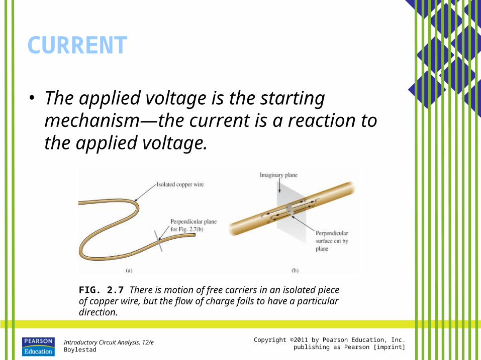
• The applied voltage is the starting mechanism—the current is a reaction to the applied voltage.
FIG. 2.7 There is motion of free carriers in an isolated piece of copper wire, but the flow of charge fails to have a particular direction.

Introductory Circuit Analysis, 12/eBoylestad
Copyright ©2011 by Pearson Education, Inc.publishing as Pearson [imprint]
CURRENT
FIG. 2.8 Motion of negatively charged electrons in a copper wire when placed across battery terminals with a difference in potential of volts (V).

Introductory Circuit Analysis, 12/eBoylestad
Copyright ©2011 by Pearson Education, Inc.publishing as Pearson [imprint]
CURRENT
FIG. 2.9 Basic electric circuit.
Introductory Circuit Analysis, 12/eBoylestad
Copyright ©2011 by Pearson Education, Inc.publishing as Pearson [imprint]
CURRENT
• The unit of current measurement, ampere, was chosen to honor the efforts of André Ampère in the study of electricity in motion.

Introductory Circuit Analysis, 12/eBoylestad
Copyright ©2011 by Pearson Education, Inc.publishing as Pearson [imprint]
CURRENT
• In summary, therefore, the applied voltage (or potential difference) in an electrical/electronics system is the “pressure” to set the system in motion, and the current is the reaction to that pressure.
Introductory Circuit Analysis, 12/eBoylestad
Copyright ©2011 by Pearson Education, Inc.publishing as Pearson [imprint]
CURRENTSafety Considerations
• It is important to realize that even small levels of current through the human body can cause serious, dangerous side effects.
• Experimental results reveal that the human body begins to react to currents of only a few milliamperes.
• Although most individuals can withstand currents up to perhaps 10 mA for very short periods of time without serious side effects, any current over 10 mA should be considered dangerous.

Introductory Circuit Analysis, 12/eBoylestad
Copyright ©2011 by Pearson Education, Inc.publishing as Pearson [imprint]
VOLTAGE SOURCES
• The term dc, used throughout this text, is an abbreviation for direct current, which encompasses all systems where there is a unidirectional (one direction) flow of charge.
FIG. 2.11 Standard symbol for a dc voltage source.

Introductory Circuit Analysis, 12/eBoylestad
Copyright ©2011 by Pearson Education, Inc.publishing as Pearson [imprint]
VOLTAGE SOURCES
• In general, dc voltage sources can be divided into three basic types: – Batteries (chemical action or solar
energy)– Generators (electromechanical), and – Power supplies (rectification—a
conversion process to be described in your electronics courses).

Introductory Circuit Analysis, 12/eBoylestad
Copyright ©2011 by Pearson Education, Inc.publishing as Pearson [imprint]
VOLTAGE SOURCESBatteries
• General Information
• Primary Cells (Non-rechargeable)
• Secondary Cells (Rechargeable)– Lead-Acid– Nickel–Metal Hydride (NiMH)– Lithium-ion (Li-ion)

Introductory Circuit Analysis, 12/eBoylestad
Copyright ©2011 by Pearson Education, Inc.publishing as Pearson [imprint]
VOLTAGE SOURCESBatteries
FIG. 2.12 Alkaline primary cell: (a) Cutaway of cylindrical Energizer® cell; (b) various types of Eveready Energizer® primary cells.

Introductory Circuit Analysis, 12/eBoylestad
Copyright ©2011 by Pearson Education, Inc.publishing as Pearson [imprint]
VOLTAGE SOURCESBatteries
FIG. 2.13 Lithium primary batteries.

Introductory Circuit Analysis, 12/eBoylestad
Copyright ©2011 by Pearson Education, Inc.publishing as Pearson [imprint]
VOLTAGE SOURCESBatteries
FIG. 2.14 Maintenance-free 12 V (actually 12.6 V) lead-acid battery.

Introductory Circuit Analysis, 12/eBoylestad
Copyright ©2011 by Pearson Education, Inc.publishing as Pearson [imprint]
VOLTAGE SOURCESBatteries
FIG. 2.15 Nickel–metal hydride (NiMH) rechargeable batteries.

Introductory Circuit Analysis, 12/eBoylestad
Copyright ©2011 by Pearson Education, Inc.publishing as Pearson [imprint]
VOLTAGE SOURCESBatteries
FIG. 2.16 Dell laptop lithium-ion battery: 11.1 V, 4400 mAh.

Introductory Circuit Analysis, 12/eBoylestad
Copyright ©2011 by Pearson Education, Inc.publishing as Pearson [imprint]
VOLTAGE SOURCESSolar Cell
FIG. 2.17 Solar System: (a) panels on roof of garage; (b) system operation.

Introductory Circuit Analysis, 12/eBoylestad
Copyright ©2011 by Pearson Education, Inc.publishing as Pearson [imprint]
VOLTAGE SOURCESGenerators
• The dc generator is quite different from the battery, both in construction and in mode of operation.
• When the shaft of the generator is rotating at the nameplate speed due to the applied torque of some external source of mechanical power, a voltage of rated value appears across the external terminals.
• The terminal voltage and power-handling capabilities of the dc generator are typically higher than those of most batteries, and its lifetime is determined only by its construction.

Introductory Circuit Analysis, 12/eBoylestad
Copyright ©2011 by Pearson Education, Inc.publishing as Pearson [imprint]
VOLTAGE SOURCESGenerators
FIG. 2.18 dc generator.

Introductory Circuit Analysis, 12/eBoylestad
Copyright ©2011 by Pearson Education, Inc.publishing as Pearson [imprint]
VOLTAGE SOURCESPower Supplies
• The dc supply encountered most frequently in the laboratory uses the rectification and filtering processes as its means toward obtaining a steady dc voltage.
FIG. 2.19 A 0 V to 60 V, 0 to 1.5 A digital display dc power supply

Introductory Circuit Analysis, 12/eBoylestad
Copyright ©2011 by Pearson Education, Inc.publishing as Pearson [imprint]
VOLTAGE SOURCESPower Supplies
FIG. 2.20 dc laboratory supply: (a) available terminals; (b) positive voltage with respect to (w.r.t.) ground; (c) negative voltage w.r.t. ground; (d) floating supply.
Introductory Circuit Analysis, 12/eBoylestad
Copyright ©2011 by Pearson Education, Inc.publishing as Pearson [imprint]
VOLTAGE SOURCESFuel Cells
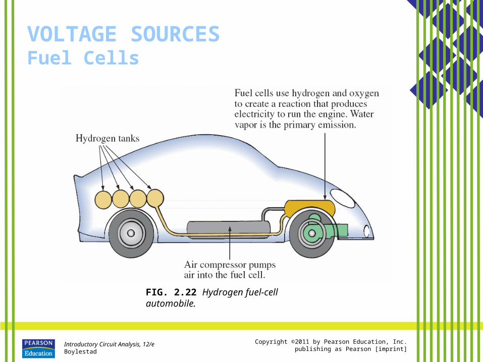
• One of the most exciting developments in recent years has been the steadily rising interest in fuel cells as an alternative energy source.
• Fuel cells are now being used in small stationary power plants, transportation (buses), and a wide variety of applications where portability is a major factor, such as the space shuttle.
• Millions are now being spent by major automobile manufacturers to build affordable fuel-cell vehicles.

Introductory Circuit Analysis, 12/eBoylestad
Copyright ©2011 by Pearson Education, Inc.publishing as Pearson [imprint]
VOLTAGE SOURCESFuel Cells
FIG. 2.21 Fuel cell (a) components; (b) basic construction.
Introductory Circuit Analysis, 12/eBoylestad
Copyright ©2011 by Pearson Education, Inc.publishing as Pearson [imprint]
VOLTAGE SOURCESFuel Cells
FIG. 2.22 Hydrogen fuel-cell automobile.

Introductory Circuit Analysis, 12/eBoylestad
Copyright ©2011 by Pearson Education, Inc.publishing as Pearson [imprint]
AMPERE-HOUR RATING
• The most important piece of data for any battery (other than its voltage rating) is its ampere-hour (Ah) rating.
• You have probably noted in the photographs of batteries in this chapter that both the voltage and the ampere-hour rating have been provided for each battery.– The ampere-hour (Ah) rating provides an
indication of how long a battery of fixed voltage will be able to supply a particular current.

Introductory Circuit Analysis, 12/eBoylestad
Copyright ©2011 by Pearson Education, Inc.publishing as Pearson [imprint]
BATTERY LIFE FACTORS
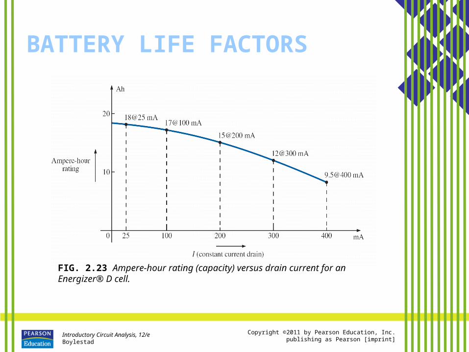
• The previous section made it clear that the life of a battery is directly related to the magnitude of the current drawn from the supply.
• However, there are factors that affect the given ampere-hour rating of a battery, so we may find that a battery with an ampere-hour rating of 100 can supply a current of 10 A for 10 hours but can supply a current of 100 A for only 20 minutes rather than the full 1 hour calculated using Eq. (2.8). – In other words, the capacity of a battery (in ampere-
hours) will change with change in current demand.
Introductory Circuit Analysis, 12/eBoylestad
Copyright ©2011 by Pearson Education, Inc.publishing as Pearson [imprint]
BATTERY LIFE FACTORS
FIG. 2.23 Ampere-hour rating (capacity) versus drain current for an Energizer® D cell.
Introductory Circuit Analysis, 12/eBoylestad
Copyright ©2011 by Pearson Education, Inc.publishing as Pearson [imprint]
BATTERY LIFE FACTORS
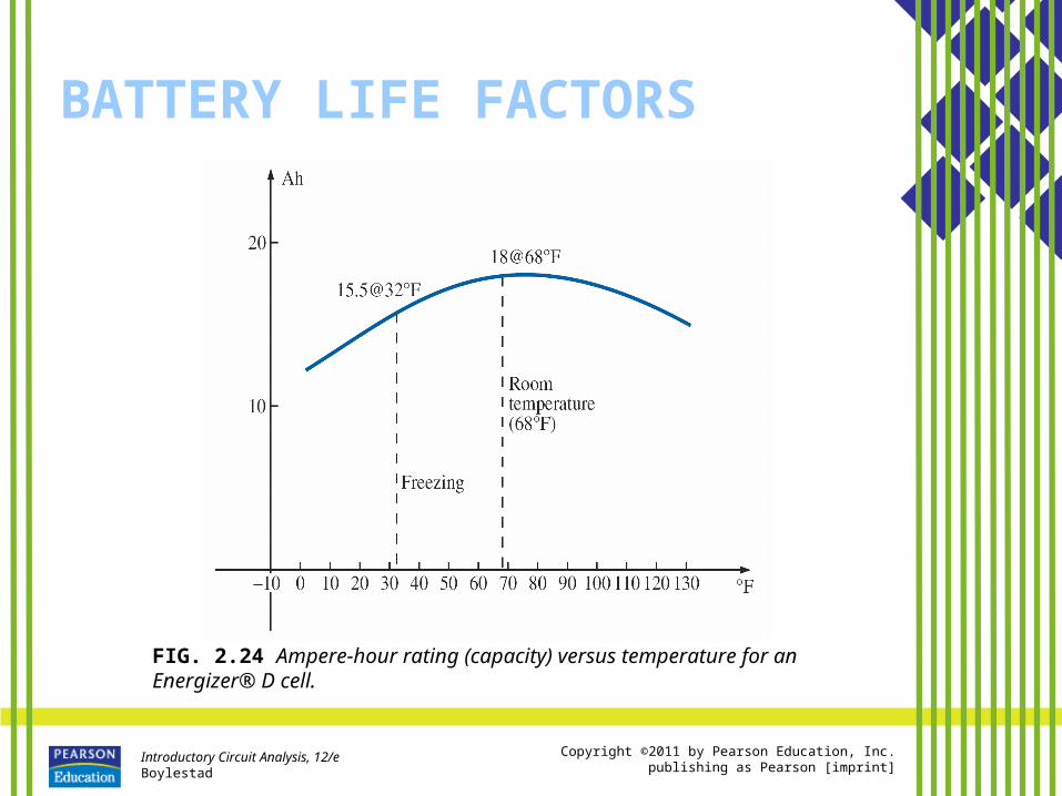
FIG. 2.24 Ampere-hour rating (capacity) versus temperature for an Energizer® D cell.

Introductory Circuit Analysis, 12/eBoylestad
Copyright ©2011 by Pearson Education, Inc.publishing as Pearson [imprint]
BATTERY LIFE FACTORS
FIG. 2.25 Terminal voltage versus discharge time for specific drain currents for an Energizer® D cell.
Introductory Circuit Analysis, 12/eBoylestad
Copyright ©2011 by Pearson Education, Inc.publishing as Pearson [imprint]
CONDUCTORS AND INSULATORS
• Different wires placed across the same two battery terminals allow different amounts of charge to flow between the terminals.
• Many factors, such as the density, mobility, and stability characteristics of a material, account for these variations in charge flow. – In general, however, conductors are those
materials that permit a generous flow of electrons with very little external force (voltage) applied.
– In addition, good conductors typically have only one electron in the valence (most distant from the nucleus) ring.

Introductory Circuit Analysis, 12/eBoylestad
Copyright ©2011 by Pearson Education, Inc.publishing as Pearson [imprint]
CONDUCTORS AND INSULATORS
TABLE 2.1 Relative conductivity of various materials

Introductory Circuit Analysis, 12/eBoylestad
Copyright ©2011 by Pearson Education, Inc.publishing as Pearson [imprint]
CONDUCTORS AND INSULATORS
FIG. 2.26 Various types of insulators and their applications. (a) Fi-Shock extender insulator; (b) Fi-Shock corner insulator; (c) Fi-Shock screw-in post insulator.

Introductory Circuit Analysis, 12/eBoylestad
Copyright ©2011 by Pearson Education, Inc.publishing as Pearson [imprint]
CONDUCTORS AND INSULATORS
TABLE 2.2 Breakdown strength of some common insulators.

Introductory Circuit Analysis, 12/eBoylestad
Copyright ©2011 by Pearson Education, Inc.publishing as Pearson [imprint]
SEMICONDUCTORS
• Semiconductors are a specific group of elements that exhibit characteristics between those of insulators and those of conductors.
• Semiconductor materials typically have four electrons in the outermost valence ring.
Introductory Circuit Analysis, 12/eBoylestad
Copyright ©2011 by Pearson Education, Inc.publishing as Pearson [imprint]
AMMETERS AND VOLTMETERS
• It is important to be able to measure the current and voltage levels of an operating electrical system to check its operation, isolate malfunctions, and investigate effects impossible to predict on paper.
• As the names imply, ammeters are used to measure current levels; voltmeters, the potential difference between two points.
• If the current levels are usually of the order of milliamperes, the instrument will typically be referred to as a milliammeter, and if the current levels are in the microampere range, as a microammeter.

Introductory Circuit Analysis, 12/eBoylestad
Copyright ©2011 by Pearson Education, Inc.publishing as Pearson [imprint]
AMMETERS AND VOLTMETERS
FIG. 2.27 Voltmeter connection for an up-scale (+) reading.

Introductory Circuit Analysis, 12/eBoylestad
Copyright ©2011 by Pearson Education, Inc.publishing as Pearson [imprint]
AMMETERS AND VOLTMETERS
FIG. 2.28 Ammeter connection for an up-scale (+) reading.

Introductory Circuit Analysis, 12/eBoylestad
Copyright ©2011 by Pearson Education, Inc.publishing as Pearson [imprint]
AMMETERS AND VOLTMETERS
FIG. 2.29 Volt-ohm-milliammeter (VOM) analog meter.

Introductory Circuit Analysis, 12/eBoylestad
Copyright ©2011 by Pearson Education, Inc.publishing as Pearson [imprint]
AMMETERS AND VOLTMETERS
FIG. 2.30 Digital multimeter (DMM).

Introductory Circuit Analysis, 12/eBoylestad
Copyright ©2011 by Pearson Education, Inc.publishing as Pearson [imprint]
APPLICATIONS
• Flashlight
• 12 V Car Battery Charger
• Answering Machines/Phones dc Supply

Introductory Circuit Analysis, 12/eBoylestad
Copyright ©2011 by Pearson Education, Inc.publishing as Pearson [imprint]
APPLICATIONS
FIG. 2.31 (a) Eveready® D cell flashlight; (b) electrical schematic of flashlight of part (a); (c) Duracell® Powercheck™ D cell battery.

Introductory Circuit Analysis, 12/eBoylestad
Copyright ©2011 by Pearson Education, Inc.publishing as Pearson [imprint]
APPLICATIONS
FIG. 2.32 Battery charger: (a) external appearance; (b) internal construction.

Introductory Circuit Analysis, 12/eBoylestad
Copyright ©2011 by Pearson Education, Inc.publishing as Pearson [imprint]
APPLICATIONS
FIG. 2.33 Electrical schematic for the battery charger of Fig. 2.32.

Introductory Circuit Analysis, 12/eBoylestad
Copyright ©2011 by Pearson Education, Inc.publishing as Pearson [imprint]
APPLICATIONS
FIG. 2.34 Answering machine/phone 9 V dc supply.

Introductory Circuit Analysis, 12/eBoylestad
Copyright ©2011 by Pearson Education, Inc.publishing as Pearson [imprint]
APPLICATIONS
FIG. 2.35 Internal construction of the 9 V dc supply in Fig. 2.34.