materials chemistry and physics - ohio university of co2... · inhibition of co2 corrosion of...
TRANSCRIPT

at SciVerse ScienceDirect
Materials Chemistry and Physics 136 (2012) 1092e1102
Contents lists available
Materials Chemistry and Physics
journal homepage: www.elsevier .com/locate/matchemphys
Inhibition of CO2 corrosion of carbon steel with 1% Cr
L.D. Paolinelli a,*, B. Brownb, S.N. Simison a, S. Nesic b
aCorrosion Division, INTEMA-CONICET, University of Mar del Plata, Juan B. Justo 4302 (B7608FDQ), Argentinab Institute for Corrosion and Multiphase Technology, Ohio University, Athens, OH 45701, USA
h i g h l i g h t s
< The imidazoline-based inhibitor used has a lower performance on carbon steel with 1% Cr.< Inhibitor adsorption kinetics were enhanced with the increase of rotation rate.< Fluid flow velocity may be an important parameter for the inhibition of carbon steel with 1% Cr.< Effective inhibition of carbon steel with 1% Cr was achieved only at higher rotation rates.< Localized corrosion was found for carbon steel with 1% Cr inhibited at the lower rotation rate.
a r t i c l e i n f o
Article history:Received 24 November 2011Received in revised form13 June 2012Accepted 23 August 2012
Keywords:CorrosionAlloysElectrochemical techniquesSEM
* Corresponding author. Tel.: þ54 223 4816600x24E-mail address: [email protected] (L.D. Pao
0254-0584/$ e see front matter � 2012 Elsevier B.V.http://dx.doi.org/10.1016/j.matchemphys.2012.08.055
a b s t r a c t
One of the most employed methods for CO2 corrosion control in oil and gas production and trans-portation industry is the use of carbon and low alloy steels in conjunction with corrosion inhibitors. Theinhibitor performance can be influenced by the microstructure and chemical composition of the steel. Inprevious works, it was shown that 1% Cr addition to carbon steel decreased the protectiveness ofa commercial imidazoline-based inhibitor. However, it was suspected that changing the flow rates maymodify the inhibitor behaviour. In the present work, the performance of an imidazoline-based inhibitorwas investigated on two carbon steels one with the other without 1% Cr, under different flow rates.
Corrosion and corrosion inhibition experiments were carried out using a rotating cylinder electrode atdifferent rotation speeds in a deoxygenated 5 wt.% NaCl CO2-saturated solution at 40 �C, pH 6 with andwithout inhibitor addition. Electrochemical measurements were taken during each experiment andsample surfaces were analyzed after each experiment. Inhibitor performance was found to be dependenton flow velocity and chemical composition of carbon steel.
� 2012 Elsevier B.V. All rights reserved.
1. Introduction
Little is known regarding CO2 corrosion inhibition of Cr-containing carbon steels. It has been reported that steels alloyedwith small Cr contents (0.5e1%) are less efficiently inhibited thanCr-free carbon steels [1e4]. However, other authors tested variousinhibitors on carbon steels with and without 0.5% Cr and found thatall the employed compounds achieved acceptable efficiencies onboth steels [5]. Recently, it has been shown that the addition of 1%Cr in carbon steel has a negative effect on the adsorption ofa commercial imidazoline-based inhibitor, leading to localizedcorrosion, more or less severe, depending on steel microstructureand pre-corrosion period [6]. It needs to be noted that the latter setof results were obtained under low flow rate (glass cells with low
7; fax: þ54 223 4810046.linelli).
All rights reserved.
speed magnetic stirring), thus experimentation under morerepresentative hydrodynamic conditions would be valuable.
It is known that CO2 corrosion can be influenced by the hydro-dynamic conditions, due to changes in transport of reactive speciesto surface and differences in the formation and destruction ofprotective corrosion product layers. The main way to characterizethe intensity of the flow is thewall shear stresses [7,8]. Additionally,it has long been suspected that corrosion inhibitors performancecan be also affected by the flow regime (in multiphase flow) andflow velocity. For single phase flow, it has been reported that lowfluid velocities or stagnant conditions produce an enhancement ofprotective properties of the inhibitor films [9]. This beneficial effectwould be related to smaller flow-induced shear stresses applied onthe inhibitor film and the decrease in the availability of corrosivespecies given by a lower mass transfer rate. Nevertheless, otherresearchers have found that inhibitors performance or inhibitorprotective films are not affected by wall shear stresses for the rangeof flow velocities usually used in service [10,11].

Table 1Chemical composition of the tested materials (major alloying elements).
Materials (% wt.) Fe balance
C Mn Si Cr
CeMn 0.38 0.99 0.33 0.171Cr 0.39 1.01 0.26 1.02
L.D. Paolinelli et al. / Materials Chemistry and Physics 136 (2012) 1092e1102 1093
One of the most cost-effective and therefore most employedmethods for CO2 corrosion control in oil and gas production andtransportation industry is the use of carbon and low alloy steels inconjunction with corrosion inhibitors [12]. Organic substancescontaining nitrogen have been successfully applied for CO2 corro-sion inhibition of carbon steel. Especially, corrosion inhibitorsbased on amides derivatives, such as imidazolines (e.g. oleic imi-dazoline) are extensively used to protect carbon steel tubes andpipes [9].
Steel metallurgy has also been employed as a method ofcorrosion control for CO2 corrosion. A positive contribution of lowCr additions (up to 5%) to the corrosion resistance of standardcarbon steel has been reported [12e18]. This improvement is basedon the formation of a stable protective chromium containing oxidefilm [17,18]. Nevertheless, some researchers have found an adversebehaviour particularly for Cr contents from 0.5 to 1.5% [5,6,12,16,19].
The aim of the present work is to investigate the performance ofan imidazoline-based inhibitor on two carbon steels with andwithout 1% Cr under different flow velocities employing a RCE(Rotating Cylinder Electrode) device.
2. Experimental
Two types of carbon steels for oil and gas production tubes wereused for the electrochemical experiments. Their chemical compo-sitions (wt.%) are listed in Table 1. A laboratory heat treatment ofquenching and tempering (austenized at 890 �C, water quenchingand 1 h tempering at 700 �C) was performed on both steels in order
Fig. 1. Steel microstructure: A) 1Cr, B) CeMn. High
to obtain the same microstructure with globular cementitemorphology (Fig. 1).
Working electrodes were machined from these heat-treatedmaterials into 10 mm diameter cylinders with a total exposedarea of 4.2 cm2. For the electrochemical test, surfaces were polishedto 600-grit SiC paper, washed with distilled water and rinsed andmaintained in acetone until the immersion procedure.
Experiments were conducted at open circuit potential usinga rotating cylinder electrode. The rotation speeds were 250, 1000and 2500 rpm, leading to peripheral flow velocities of 0.13, 0.52 and1.3 m s�1 and turbulent Reynolds numbers of 990, 3880 and 9940,respectively. A three-electrode electrochemical cell with a workingvolume of 2 L was used. The test media was a deoxygenated 5 wt. %NaCl (analytical-reagent grade) solution saturated with CO2, 40 �C,atmospheric pressure and pH 6 adjusted adding deoxygenated 1 MNaHCO3 solution. Positive CO2 pressure was maintainedthroughout the experiments to avoid air ingress. The referenceelectrode was Ag/AgCl and the counter electrode was a platinumwire. Fig. 2 depicts a scheme of the test electrochemical cellemployed and its accessories.
Prior to electrode immersion, a commercial imidazoline-basedinhibitor was added in a concentration recommended by manu-facturer e 50 ppm. A schematic representation of the imidazolinemolecule is shown in Fig. 3. Inhibitor performance was monitoredafter 1, 1.5, 2 and 24 h by means of electrochemical techniques:corrosion potential (Ecorr), polarization resistance (LPR) and elec-trochemical impedance spectroscopy (EIS), employing a Gamry�
CMS100 potentiostat.LPR experiments were done by polarizing the working electrode
�0.01 V versus Ecorr with a sweep rate of 10�4 V s�1. EIS wasmeasured at Ecorr using an applied potential of �0.005 V rms witha frequency interval of 60,000 to 0.003 Hz. Ecorr was monitoredbefore each DC and AC analyses. The electrochemical data wereanalyzed using Gamry� software and Zview 2� software. Corrosionrates (CR) were calculated with polarization resistance (Rp) valuesobtained from LPR measurements, using the SterneGeary equationwith a proportionality factor B ¼ 0.022 V [6].
magnification: C) 1Cr, D) CeMn. Nital etching.
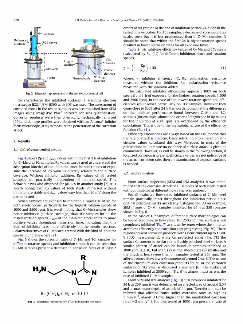
Fig. 2. Schematic representation of the test electrochemical cell.
L.D. Paolinelli et al. / Materials Chemistry and Physics 136 (2012) 1092e11021094
To characterize the inhibited surfaces, a scanning electronmicroscope JEOL� JSM-6390 with EDS was used. The assessment ofcorroded zones in the tested samples was accomplished from SEMimages using Image-Pro Plus� software for area quantification.Corrosion products were then chemically/mechanically removed[20] and damage profiles were obtained with an Alicona� infinitefocus microscope (IFM) tomeasure the penetration of the corrosionattack.
3. Results
3.1. D.C. electrochemical results
Fig. 4 shows Rp and Ecorr values within the first 2 h of inhibitionfor CeMn and 1Cr samples. Rp values can be used to understand theadsorption kinetics of the inhibitor, since for short times of expo-sure the increase of Rp value is directly related to the surfacecoverage. Without inhibitor addition, Rp values of all testedsamples are practically independent of rotation speed. Thisbehaviour was also observed for pH > 5 in another study [7]. It isworth noting that Rp values of both steels immersed withoutinhibitor are stable and Ecorr values vary less than 20 mV along theperiod tested.
When samples are exposed to inhibitor, a rapid rise of Rp forboth steels occurs, particularly for the highest rotation speeds of1000 and 2500 rpm. It is worth noting that CeMn samples showbetter inhibition (surface coverage) than 1Cr samples for all thetested rotation speeds. Ecorr of the inhibited steels shifts to morepositive values throughout immersion time, indicating that thiskind of inhibitor acts more efficiently on the anodic reaction.Polarization curves of CeMn steel treatedwith this kind of inhibitorcan be found elsewhere [21].
Fig. 5 shows the corrosion rates of CeMn and 1Cr samples fordifferent rotation speeds and inhibition times. It can be seen thatCeMn samples present a decrease in corrosion rates of at least 2
Fig. 3. Schematic representation of an imidazoline molecule.
orders of magnitude at the end of inhibition period (24 h) for all thetested flow velocities. For 1Cr samples, a decrease of corrosion ratesis also seen, but it is less pronounced than in CeMn samples. Itshould be noted that within the first 24 h, higher rotation speedsresulted in lower corrosion rates for all exposure times.
Table 2 lists inhibitor efficiency values of CeMn and 1Cr steels(calculated by Eq. (1)) for different inhibition times and rotationspeeds.
h ¼�1� Rp
Rp0
�$100 (1)
where: h: inhibitor efficiency (%), Rp: polarization resistancemeasured without the inhibitor, Rp0: polarization resistancemeasured with the inhibitor added.
The calculated inhibitor efficiencies approach 100% on bothsteels from 1 h of exposure for the highest rotation speeds (1000and 2500 rpm). In the case of the lowest rotation speed, the effi-ciencies result lower particularly on 1Cr samples; however theycome close to 100% after 24 h. It is worth noting that the differenceson the inhibitor performance found between CeMn and 1Crsamples (for example, almost one order of magnitude in Rp valuesfor the inhibition at 2500 rpm) are overlooked by the efficiencycalculations. This is due to the asymptotic nature of the efficiencyfunction (Eq. (1)).
Efficiency calculations are always based on the assumption thatthe rate of attack is uniform. Users select inhibitors based on effi-ciencies values calculated this way. Moreover, in most of thepublications in literature no evidence of surface attack is given orcommented. However, as will be shown in the following section, iflocalized corrosion is present, efficiency values are not indicative ofthe actual corrosion rate, then an examination of exposed surfacesis needed.
3.2. Surface analysis
From surface inspection (SEM and IFM analysis), it was deter-mined that the corrosive attack of all samples of both steels testedwithout inhibitor at different flow rates was uniform.
For all evaluated flow rates, inhibited surfaces of CeMn steelremain practically intact throughout the inhibition period sinceoriginal polishing marks are clearly distinguished. As an example,SEM images of CeMn samples inhibited for 24 h at 250 rpm areshown in Fig. 6.
In the case of 1Cr samples, different surface morphologies canbe found according to flow rates. For 250 rpm, the surface is notcompletely inhibited (Fig. 7) as shown by zones where the inhibitoracted less efficiently and corrosion kept progressing (Fig. 7C). Theseregions present corrosion products with Cr enrichment up to 12 wt.% (EDS measurement), while on protected zones (Fig. 7E) thesurface Cr content is similar to the freshly polished steel surface. Asimilar pattern of attack can be found on samples inhibited at1000 rpm (Fig. 8), but in this case, the affected area is smaller andthe attack is less severe than on samples tested at 250 rpm. Theaffected zones show lower Cr contents of around 7wt. %. The natureof the chromium-rich corrosion products found in the corrodedsurfaces of 1Cr steel is discussed elsewhere [6]. The surface ofsamples inhibited at 2500 rpm (Fig. 9) is almost intact as was thecase of inhibited CeMn samples.
From SEM and IFM analyses (Fig.10) of 1Cr coupons inhibited for24 h at 250 rpm it was determined an affected area of around 2.5%and a maximum depth of attack of 14 mm. Therefore, it can beinferred that affected zones suffer corrosion rates as high as5 mm y�1, almost 3 times higher than the uninhibited corrosionrate (w2 mm y�1). Samples tested at 1000 rpm present a ratio of

Fig. 4. Rp and Ecorr versus immersion time for inhibited and uninhibited CeMn and 1Cr steels.
L.D. Paolinelli et al. / Materials Chemistry and Physics 136 (2012) 1092e1102 1095
affected area of about 0.03% and a maximum depth of damage of6 mm. In this case maximum estimated corrosion rate of affectedzones is similar to the uninhibited measured one.
3.3. EIS results
Fig. 11 shows impedance spectra of CeMn and 1Cr samplesinhibited at different rotation speeds. Uninhibited samplesresponse was added as a reference.
For samples exposed without inhibitor addition, only one timeconstant is distinguishable in the phase angle (a) versus frequency(f) plot. This time constant is related to the corrosion processes atthe metal/electrolyte interface and can be modelled by a Randlesequivalent circuit that allows charge transfer resistance (RCT),electrolyte resistance (RS) and double layer capacitance calculation.For best fitting of experimental data, the Randles circuit wasmodified replacing the ideal capacitor by a constant phase element(CPE) as is shown in Fig.12a as ZCPEdl. The impedance of a CPE can beexpressed as:
ZCPE ¼ Y�1ðiuÞ�n (2)
Fig. 5. Corrosion rates versus immersion time for inhibited CeMn and Cr steels.
where: Y is proportional to the capacitance of the interface [22], i isO�1, and n represents a phase shift.
After 2 h of exposure to an inhibited solution, at least two timeconstants can be detected from a versus f plot for both steels. Thehigh frequency time constant would indicate the presence ofa protective and isolating inhibitor film, while the low frequencytime constant could be related to corrosion processes at the sites ofmetal surface uncovered by the inhibitor film [21,23,24]. In order tomodel this behaviour, the equivalent circuit illustrated in Fig. 12bwas proposed. It represents a porous inhibitor film formed onmetalsurface, in which ZCPEFO is related to the non-ideal capacitance ofthe inhibitor film, RFO to the inhibitor film pore resistance and ZCPEdlto the non-ideal capacitance of the double layer of the metal/electrolyte interface. However, experimental data shows a morecomplex behaviour in most of the tested conditions, especially for24 h of inhibition. Thus, an additional circuit shown in Fig. 12c wasemployed for the modelling, which is in very good agreement withthe experimental data. This equivalent circuit corresponds toa bilayer porous inhibitor film [21,25] where the inner layer isformed on the metal surface and the outer layer is on top of thelatter, and both have different electrical properties. ZCPEFO and RFOand ZCPEFI and RFI are related to the non-ideal capacitance and to thepore resistance of the outer and inner layer of the inhibitor film,respectively.
Equivalent circuits presented in Fig. 12b and c are developedunder the assumption of generalized inhibition (on wholesurface), which is true for CeMn samples inhibited at all testedrotation rates and 1Cr samples inhibited at 2500 rpm. However,for 1Cr samples inhibited at 250 and 1000 rpm, the occurrence oflocalized corrosion was shown (Section 3.2). In this circumstance,the use of equivalent circuits representing generalized inhibitionmay give erroneous estimation of the impedance parameters ofthe inhibitor film as well as of the metaleelectrolyte chargetransfer depending on the relationship between the localizedcorrosion current and the total corrosion current of the spec-imen. If the localized/total current ratio results in a small value
Table 2Inhibitor efficiencies (h%) versus immersion time for CeMn and 1Cr steels.
Exposure (h) CeMn 1Cr
250 rpm 1000 rpm 2500 rpm 250 rpm 1000 rpm 2500 rpm
1 88.1 97.1 99.6 82.4 96.8 98.61.5 91.7 98.5 99.7 85.2 97.5 98.82 93.1 99.5 99.7 86.8 97.7 98.924 99.8 99.9 99.9 96.4 99.3 99.7

Fig. 6. Surfaces of CeMn samples inhibited for 24 h at 250 rpm. A) and B) correspond to low and high magnification, respectively.
L.D. Paolinelli et al. / Materials Chemistry and Physics 136 (2012) 1092e11021096
(e.g. less than 0.1), it means that the impedance spectrum of thespecimen can be mainly attributed to the electrochemicalbehaviour of the inhibited surface. On the contrary, if localized/total current ratio approaches 1, the impedance spectrum can bemainly attributed to the electrochemical behaviour of the local-ized corrosion sites.
Fig. 7. Surfaces of 1Cr samples inhibited for 24 h at 250 rpm. A) General view of an uninhibi(white rectangle in picture A). C) Corrosion products of the uninhibited zone (magnificationzones (magnification of region (b) in picture A). E) Inhibited zone (magnification of region
The former analysis wasmade for inhibited 1Cr samples affectedby localized corrosion in order to determine the validity ofemploying the equivalent circuits shown in Fig. 12 for inhibitor filmcharacterization. Total and localized corrosion currents werecalculated for each inhibited specimen. The total corrosion currentsof the specimens were estimated from their Rp values using Sterne
ted zone. B) Magnification of the border between the inhibited and the corroded zonesof region (a) in picture A). D) Transition zone between the inhibited and the corroded(c) in picture A).
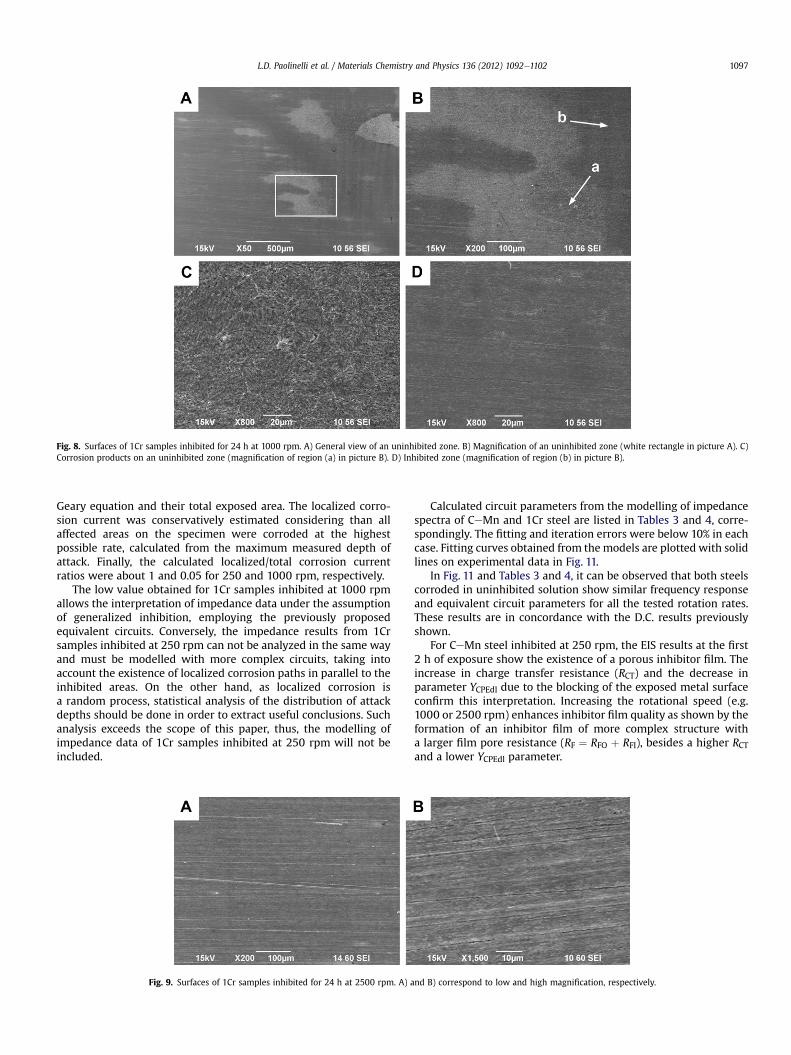
Fig. 8. Surfaces of 1Cr samples inhibited for 24 h at 1000 rpm. A) General view of an uninhibited zone. B) Magnification of an uninhibited zone (white rectangle in picture A). C)Corrosion products on an uninhibited zone (magnification of region (a) in picture B). D) Inhibited zone (magnification of region (b) in picture B).
L.D. Paolinelli et al. / Materials Chemistry and Physics 136 (2012) 1092e1102 1097
Geary equation and their total exposed area. The localized corro-sion current was conservatively estimated considering than allaffected areas on the specimen were corroded at the highestpossible rate, calculated from the maximum measured depth ofattack. Finally, the calculated localized/total corrosion currentratios were about 1 and 0.05 for 250 and 1000 rpm, respectively.
The low value obtained for 1Cr samples inhibited at 1000 rpmallows the interpretation of impedance data under the assumptionof generalized inhibition, employing the previously proposedequivalent circuits. Conversely, the impedance results from 1Crsamples inhibited at 250 rpm can not be analyzed in the same wayand must be modelled with more complex circuits, taking intoaccount the existence of localized corrosion paths in parallel to theinhibited areas. On the other hand, as localized corrosion isa random process, statistical analysis of the distribution of attackdepths should be done in order to extract useful conclusions. Suchanalysis exceeds the scope of this paper, thus, the modelling ofimpedance data of 1Cr samples inhibited at 250 rpm will not beincluded.
Fig. 9. Surfaces of 1Cr samples inhibited for 24 h at 2500 rpm. A) a
Calculated circuit parameters from the modelling of impedancespectra of CeMn and 1Cr steel are listed in Tables 3 and 4, corre-spondingly. The fitting and iteration errors were below 10% in eachcase. Fitting curves obtained from the models are plotted with solidlines on experimental data in Fig. 11.
In Fig. 11 and Tables 3 and 4, it can be observed that both steelscorroded in uninhibited solution show similar frequency responseand equivalent circuit parameters for all the tested rotation rates.These results are in concordance with the D.C. results previouslyshown.
For CeMn steel inhibited at 250 rpm, the EIS results at the first2 h of exposure show the existence of a porous inhibitor film. Theincrease in charge transfer resistance (RCT) and the decrease inparameter YCPEdl due to the blocking of the exposed metal surfaceconfirm this interpretation. Increasing the rotational speed (e.g.1000 or 2500 rpm) enhances inhibitor film quality as shown by theformation of an inhibitor film of more complex structure witha larger film pore resistance (RF ¼ RFO þ RFI), besides a higher RCTand a lower YCPEdl parameter.
nd B) correspond to low and high magnification, respectively.

Fig. 10. Topography and cross section profile of affected areas of a 1Cr sample inhibited at 250 rpm.
L.D. Paolinelli et al. / Materials Chemistry and Physics 136 (2012) 1092e11021098

Fig. 11. Bode representation of impedance spectra for samples inhibited and uninhibited at indicated rotation rates. A) CeMn steel 2 h of inhibition, B) 1Cr steel 2 h of inhibition, C)CeMn steel 24 h of inhibition, D) 1Cr steel 24 h of inhibition.
L.D. Paolinelli et al. / Materials Chemistry and Physics 136 (2012) 1092e1102 1099
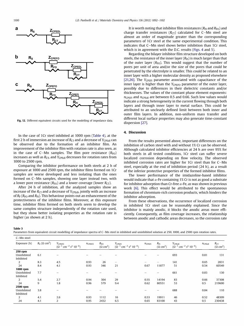
Fig. 12. Different equivalent circuits used for the modelling of impedance data.
L.D. Paolinelli et al. / Materials Chemistry and Physics 136 (2012) 1092e11021100
In the case of 1Cr steel inhibited at 1000 rpm (Table 4), at thefirst 2 h of immersion an increase of RCT and a decrease of YCPEdl canbe observed due to the formation of an inhibitor film. Animprovement of the inhibitor filmwith rotation rate is also seen, asin the case of CeMn samples. The film pore resistance (RFO)increases as well as RCT, and YCPEdl decreases for rotation rates from1000 to 2500 rpm.
Comparing the inhibitor performance on both steels at 2 h ofexposure at 1000 and 2500 rpm, the inhibitor films formed on 1Crsamples are worse developed and less isolating than the onesformed on CeMn samples, showing one layer instead two, witha lower pore resistance (RFO) and a lower coverage (lower RCT).
After 24 h of inhibition, all the analyzed samples show anincrease of the RCT and a decrease of YCPEdl, jointly with an increaseof RF (RFO and RFI). This behaviour points out an enhancement of theprotectiveness of the inhibitor films. Moreover, at this exposuretime, inhibitor films formed on both steels seem to develop thesame complex structure independently of the rotation rate used,but they show better isolating properties as the rotation rate ishigher (as shown at 2 h).
Table 3Parameters from equivalent circuit modelling of impedance spectra of CeMn steel in inh
CeMn steel
Exposure (h) RS (U cm2) YCPEFO(U�1 cm�2 sn 10�6)
nCPEFO RFO(U cm2)
YCPEFI(U�1 cm
250 rpmUninhibited 6.1 e e e e
Inhibited2 8.3 4.5 0.93 26 e
24 8.4 4.1 0.93 346 211000 rpmUninhibited 7.7 e e e e
Inhibited2 5.4 2.7 0.94 304 2924 9 1.8 0.96 579 9.4
2500 rpmUninhibited 3.8 e e e e
Inhibited2 4.1 2.6 0.93 1112 1624 4.1 2 0.95 2432 6.5
It is worth noting that inhibitor film resistances (RFI and RFO) andcharge transfer resistances (RCT) calculated for CeMn steel arealmost an order of magnitude greater than the correspondingparameters of 1Cr steel at the same experimental condition. Thisindicates that CeMn steel shows better inhibition than 1Cr steel,which is in agreement with the D.C. results (Figs. 4 and 5).
Regarding the bilayer inhibitor film structure developed on bothsteels, the resistance of the inner layer (RFI) is much larger than thatof the outer layer (RFO). This would suggest that the number ofpores per unit of area and/or the size of the pores that could bepenetrated by the electrolyte is smaller. This could be related to aninner layer with a higher molecular density as proposed elsewhere[21,26]. The YCPEFI parameter associated with capacitance of theinner layer is higher than the YCPEFO parameter of the outer layer,possibly due to differences in their dielectric constants and/orthicknesses. The values of the constant phase element exponents:nCPEFI and nCPEdl are between 0.5 and 0.66. Such low values wouldindicate a strong heterogeneity in the current flowing through bothlayers and through inner layer to metal surface. This could beattributed to an unclearly defined limit between both inner andouter film layers. In addition, non-uniform mass transfer anddifferent local surface properties may also generate time-constantdispersion [27].
4. Discussion
From the results presented above, important differences on theinhibition of carbon steel with and without 1% Cr can be observed.Although calculated inhibitor efficiencies at 24 h are over 95% forboth steels in all tested conditions, 1Cr steel can suffer severelocalized corrosion depending on flow velocity. The observedinhibited corrosion rates are higher for 1Cr steel than for CeMnsteel, especially at the end of inhibition period (24 h), as a resultof the inferior protective properties of the formed inhibitor films.
The lower performance of the imidazoline-based inhibitorwould indicate that a-Fe containing 1% Cr is not as good a substratefor inhibitor adsorption than Cr-free a-Fe, as was shown in previouswork [6]. This effect would be attributed to the spontaneousformation of chromium-rich corrosion products, which hinders theinhibitor adsorption.
From these observations, the occurrence of localized corrosionin inhibited 1Cr steel can be reasonably explained. Since theinhibitor is mainly anodic, it blocks the anodic areas more effi-ciently. Consequently, as film coverage increases, the relationshipbetween anodic and cathodic areas decreases, so the corrosion rate
ibited and uninhibited solution at 250, 1000, and 2500 rpm rotation rates.
�2 sn 10�6)nCPEFI RFI
(U cm2)YCPEdl(U�1 cm�2 sn 10�6)
nCPEdl RCT(U cm2)
e e 693 0.81 131
e e 141 0.65 28310.67 11877 51 0.54 60549
e e 661 0.83 130
0.55 14194 83 0.66 373080.62 80551 53 0.5 219600
e e 688 0.84 110
0.53 19911 46 0.52 483090.65 83100 43 0.5 230438

Table 4Parameters from equivalent circuit modelling of impedance spectra of 1Cr steel in inhibited and uninhibited solution at 250, 1000 and 2500 rpm rotation rates.
1Cr steel
Exposure (h) RS(U cm2)
YCPEFO(U�1 cm�2 sn 10�6)
nCPEFO RFO(U cm2)
YCPEFI(U�1 cm�2 sn 10�6)
nCPEFI RFI(U cm2)
YCPEdl(U�1 cm�2 sn 10�6)
nCPEdl RCT(U cm2)
250 rpmUninhibited 5.3 e e e e e e 679 0.8 1381000 rpmUninhibited 6.2 e e e e e e 680 0.82 132Inhibited2 7.2 13 0.78 203 e e e 154 0.6 609524 12 2 0.86 265 32 0.54 1468 77 0.66 18242
2500 rpmUninhibited 3.6 e e e e e e 655 0.88 112Inhibited2 3.2 4.9 0.86 338 e e e 125 0.61 917624 3.7 1.3 0.89 431 26 0.54 2695 53 0.65 33717
L.D. Paolinelli et al. / Materials Chemistry and Physics 136 (2012) 1092e1102 1101
on the uncovered zones rises (as well as the local chromiumconcentration in corrosion products) yielding higher values thanthose found in the absence of the inhibitor. Once the chromiumconcentration of uncovered zones increases, the adsorption of theinhibitor becomes more difficult thereby preventing total areacoverage and promoting the progress of the localized attack.
Under the particular flow rate conditions tested, inhibitor filmsare developed faster under higher rotation speeds for both steels.The enhancement in film formation kinetics would be related to theincrease of the species mass transfer at the surface, which isproportional to rotation rate [28,29]. A greater surface masstransfer implies that more inhibitor molecules per unit of time aretransported from the bulk of the solution to metal surface.
Similar results were found in other corrosion inhibitor studies[30,31]. This effect becomes critical for efficient inhibition of 1Crsteel, where it is necessary to accelerate the inhibitor film forma-tion to cover the metal surface rapidly in order to decrease theaccumulation of chromium-rich corrosion products.
In the case of CeMn steel, increasing rotation rate improvesshort term inhibition (less than 2 h), since important differences infilm coverage are observed. However, for longer term inhibition(24 h), the inhibitor efficiency yields practically the same value forall tested flow rates. This indicates that inhibitor film protection onCeMn steel is satisfactory independently of surfacemass transfer inthe conditions tested.
Concerning the effect of flow-induced wall shear stress on inhi-bition, the experimental results indicate that applied shear stresses(approximately: 0.2, 1.8 and 8.7 Pa for 250, 1000 and 2500 rpm,respectively [28,29]) arenot able to remove the formed inhibitorfilms.
The present results describe the performance of this type ofinhibitor under simplified experimental conditions and a con-stricted time window (24 h). For these reasons, it is difficult toextrapolate the obtained data to predict the performance of 1% Crsteels in service. In any case, this information represents a warningand emphasizes the importance of steel chemical composition andhydrodynamic conditions in inhibitor selection tests.
5. Conclusions
- The imidazoline-based inhibitor used has a lower performanceon carbon steel with 1% Cr. This behaviour can be attributed tothe spontaneous formation of chromium-rich corrosion prod-ucts, which hinder inhibitor adsorption.
- Inhibitor adsorption kinetics were enhanced with the increaseof rotation rate on both carbon steels, with and without 1% Cr.This effect would be related to the increase of mass transfer,which promotes a greater availability of inhibitor moleculesper unit of time from the bulk of the solution to metal surface.
- Fluid flow velocity may be an important parameter for theinhibition of carbon steel with 1% Cr. Effective uniformprotectionwas achieved only at higher rotation rates where theinhibitor film covered the metal surface rapidly, decreasing theaccumulation of chromium-rich corrosion products. For thelower rotation rate tested, localized corrosion was found.
Acknowledgements
This work was supported by CONICET (Argentine ResearchCouncil for Science and Technology) and ICMT (Institute forCorrosion and Multiphase Technology, Ohio University).
References
[1] S.L. Fu, J.G. García, A. Griffin, NACE Corrosion 96, NACE International, HoustonTX, USA, 1996, Paper 21.
[2] S. Kapusta, S. Canter, NACE Corrosion 1994, NACE International, Houston TX,USA, 1994, Paper 10.
[3] T. Rogne, T.G. Eggen, U. Steinsmo, NACE Corrosion 96, NACE International,Houston TX, USA, 1996, Paper 33.
[4] M.M. Salama, B.N. Brown, NACE Corrosion 2009, NACE International, HoustonTX, 2009, Paper 476.
[5] H.J. Chen, Y. Chen, NACE Corrosion 2007, NACE International, Houston TX,2007, Paper 623.
[6] L.D. Paolinelli, T. Pérez, S.N. Simison, Mater. Chem. Phys. 126 (2011) 938e947.[7] S. Nesic, J. Postlethwaite, S. Olsen, Corrosion 52 (1996) 280e294.[8] R. Nyborg, NACE Corrosion 98, NACE International, Houston TX, 1998,
Paper 48.[9] V. Jovancicevic, S. Ramachandran, P. Prince, Corrosion 55 (1999) 449e455.
[10] E. Gulbrandsen, J. Kvarekval, H. Miland, Corrosion 61 (2005) 1086e1097.[11] E. Gulbrandsen, A. Granå, Corrosion 63 (2007) 1009e1020.[12] M.B. Kermani, A. Morshed, Corrosion 59 (2003) 659e683.[13] C. de Waard, U. Lotz, A. Dugstad, NACE Corrosion 95, NACE International,
Houston TX, USA, 1995, Paper 128.[14] A. Dugstad, H. Hemmer, M. Seiersten, NACE Corrosion 2000, NACE Interna-
tional, Houston TX, USA, 2000, Paper 24.[15] P.I. Nice, H. Takabe, M. Ueda, NACE Corrosion 2000, NACE International,
Houston TX, USA, 2000, Paper 154.[16] M.B. Kermani, J.C. Gonzalez, C. Linne, M. Dougan, R. Cochrane, NACE Corrosion
2001, NACE International, Houston TX, 2001, Paper 65.[17] M.B. Kermani, J.C. Gonzalez, G.L. Turconi, D. Edmonds, G. Dicken, L. Scoppio,
NACE Corrosion 2003, NACE International, Houston TX, USA, 2003, Paper 116.[18] M.B. Kermani, J.C. Gonzalez, G.L. Turconi, T. Perez, C. Morales, NACE Corrosion
2004, NACE International, Houston TX, USA, 2004, Paper 111.[19] K. Nose, T. Ishitsuka, H. Asahi, H. Tamehiro, in: EFC (Ed.), Advances in
Corrosion Control and Materials in Oil and Gas Production (EFC 26), ManeyPublishing, London, 1999.
[20] ASTM Standard G0001-03, Standard Practice for Preparing, Cleaning, andEvaluating Corrosion Test Specimens, ASTM International, West Con-shohocken PA, USA, 2003.
[21] L.D. Paolinelli, T. Pérez, S.N. Simison, Corros. Sci. 50 (2008) 2456e2464.[22] C.H. Hsu, F. Mansfeld, Corrosion 57 (2001) 747e748.[23] D.A. López, S.N. Simison, S.R. de Sanchez, Corros. Sci. 47 (2005) 735e755.[24] V.S. Sastri, Corrosion Inhibitors. Principles and Applications, first ed. John
Wiley & Sons, Chichester, 1998.[25] W. Durnie, Development of a Structure/activity Relationship for Carbon
Dioxide Corrosion Inhibitors, Ph.D. Thesis, School of Applied Chemistry, CurtinUniversity of Technology, 2000.

L.D. Paolinelli et al. / Materials Chemistry and Physics 136 (2012) 1092e11021102
[26] Y.J. Tan, S. Bailey, B. Kinsella, Corros. Sci. 38 (1996) 1545e1561.[27] M.E. Orazem, B. Tribollet, Electrochemical Impedance Spectroscopy, John
Wiley & Sons, New Jersey, 2008.[28] D.C. Silverman, Corrosion 40 (1984) 220e226.
[29] D.C. Silverman, Corrosion 44 (1988) 42e49.[30] M. Saremi, C. Dehghanian, M.M. Sabet, Corros. Sci. 48 (2006) 1404e1412.[31] P. Bommersbach, C. Alemany-Dumont, J.-P. Millet, B. Normand, Electrochim.
Acta 51 (2006) 4011e4018.