materials manual m 46-01 revision · chapter remove pages insert pages ... by means of the...
TRANSCRIPT
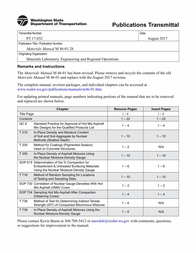
Publications TransmittalTransmittal Number
PT 17-032Date
August 2017Publication Title / Publication Number
Materials Manual M 46-01.28Originating Organization
Materials Laboratory, Engineering and Regional Operations
Remarks and InstructionsThe Materials Manual M 46-01 has been revised. Please remove and recycle the contents of the old Materials Manual M 46-01 and replace with the August 2017 revision.
The complete manual, revision packages, and individual chapters can be accessed at www.wsdot.wa.gov/publications/manuals/m46-01.htm.
For updating printed manuals, page numbers indicating portions of the manual that are to be removed and replaced are shown below.
Chapter Remove Pages Insert PagesTitle Page i – ii i – iiContents 1 – 22 1 – 22QC 8 Standard Practice for Approval of Hot Mix Asphalt
Mix Designs for the Qualified Products List 1 – 4 1 – 4
T 310 In-Place Density and Moisture Content of Soil and Soil-Aggregate by Nuclear Methods (Shallow Depth)
1 – 10 1 – 10
T 330 Method for Coatings (Pigmented Sealers) Used on Concrete Structures 1 – 2 N/A
T 355 In-Place Density of Asphalt Mixtures Using the Nuclear Moisture-Density Gauge 1 – 10 1 – 10
SOP 615 Determination of the % Compaction for Embankment & Untreated Surfacing Materials Using the Nuclear Moisture-Density Gauge
1 – 6 1 – 6
T 716 Method of Random Sampling for Locations of Testing and Sampling Sites 1 – 10 1 – 10
SOP 730 Correlation of Nuclear Gauge Densities With Hot Mix Asphalt (HMA) Cores 1 – 2 1 – 2
SOP 734 Sampling Hot Mix Asphalt After Compaction (Obtaining Cores) 1 – 4 1 – 4
T 736 Method of Test for Determining Indirect Tensile Strength (IDT) of Compacted Bituminous Mixtures 1 – 6 N/A
T 738 In-Place Density of Asphalt Mixtures Using the Nuclear Moisture-Density Gauge 1 – 6 N/A
Please contact Kevin Burns at 360-709-5412 or [email protected] with comments, questions, or suggestions for improvement to the manual.

To get the latest information, please sign up for email updates for individual publications at www.wsdot.wa.gov/publications/manuals.
Washington State Department of Transportation Materials Laboratory PO Box 47365 Olympia, WA 98504-7365 www.wsdot.wa.gov/business/materialslab/default.htm
Kevin BurnsApproved By Signature
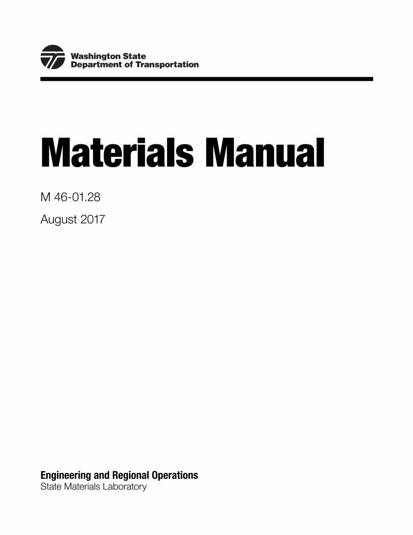
Materials ManualM 46-01.28
August 2017
Engineering and Regional OperationsState Materials Laboratory

To get the latest information on WSDOT publications, sign up for individual email updates at www.wsdot.wa.gov/publications/manuals.
Washington State Department of Transportation Engineering and Regional Operations State Materials Laboratory PO Box 47365 Olympia, WA 98504-7365
www.wsdot.wa.gov/business/materialslab/default.htm
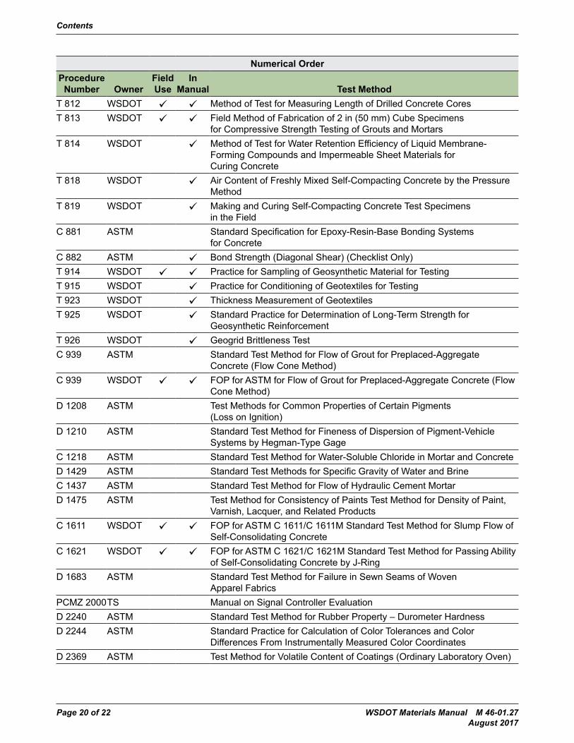
WSDOT Materials Manual M 46-01.27 Page 1 of 22 August 2017
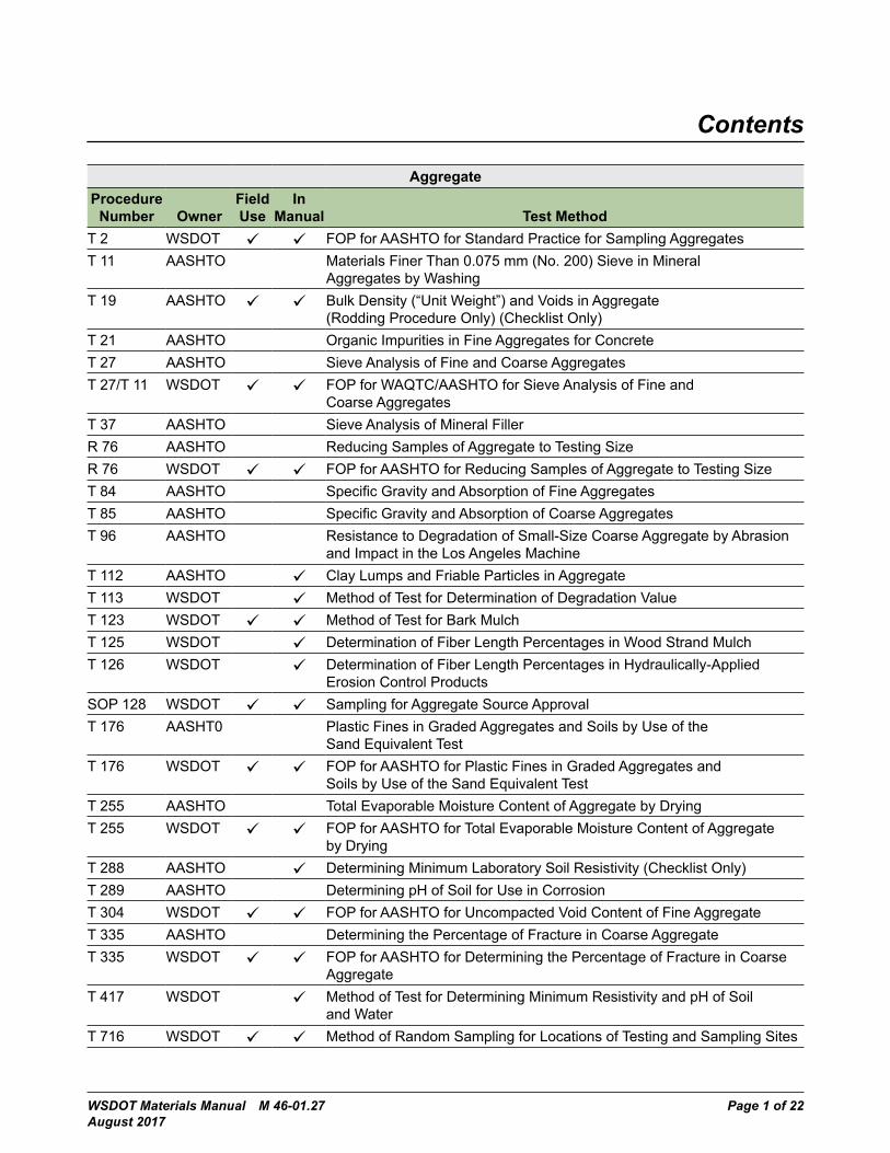
Contents
AggregateProcedure
Number OwnerField Use
In Manual Test Method
T 2 WSDOT FOP for AASHTO for Standard Practice for Sampling AggregatesT 11 AASHTO Materials Finer Than 0.075 mm (No. 200) Sieve in Mineral
Aggregates by WashingT 19 AASHTO Bulk Density (“Unit Weight”) and Voids in Aggregate
(Rodding Procedure Only) (Checklist Only)T 21 AASHTO Organic Impurities in Fine Aggregates for ConcreteT 27 AASHTO Sieve Analysis of Fine and Coarse AggregatesT 27/T 11 WSDOT FOP for WAQTC/AASHTO for Sieve Analysis of Fine and
Coarse AggregatesT 37 AASHTO Sieve Analysis of Mineral FillerR 76 AASHTO Reducing Samples of Aggregate to Testing SizeR 76 WSDOT FOP for AASHTO for Reducing Samples of Aggregate to Testing SizeT 84 AASHTO Specific Gravity and Absorption of Fine AggregatesT 85 AASHTO Specific Gravity and Absorption of Coarse AggregatesT 96 AASHTO Resistance to Degradation of Small-Size Coarse Aggregate by Abrasion
and Impact in the Los Angeles MachineT 112 AASHTO Clay Lumps and Friable Particles in AggregateT 113 WSDOT Method of Test for Determination of Degradation ValueT 123 WSDOT Method of Test for Bark MulchT 125 WSDOT Determination of Fiber Length Percentages in Wood Strand MulchT 126 WSDOT Determination of Fiber Length Percentages in Hydraulically-Applied
Erosion Control ProductsSOP 128 WSDOT Sampling for Aggregate Source ApprovalT 176 AASHT0 Plastic Fines in Graded Aggregates and Soils by Use of the
Sand Equivalent TestT 176 WSDOT FOP for AASHTO for Plastic Fines in Graded Aggregates and
Soils by Use of the Sand Equivalent TestT 255 AASHTO Total Evaporable Moisture Content of Aggregate by DryingT 255 WSDOT FOP for AASHTO for Total Evaporable Moisture Content of Aggregate
by DryingT 288 AASHTO Determining Minimum Laboratory Soil Resistivity (Checklist Only)T 289 AASHTO Determining pH of Soil for Use in CorrosionT 304 WSDOT FOP for AASHTO for Uncompacted Void Content of Fine AggregateT 335 AASHTO Determining the Percentage of Fracture in Coarse AggregateT 335 WSDOT FOP for AASHTO for Determining the Percentage of Fracture in Coarse
AggregateT 417 WSDOT Method of Test for Determining Minimum Resistivity and pH of Soil
and WaterT 716 WSDOT Method of Random Sampling for Locations of Testing and Sampling Sites
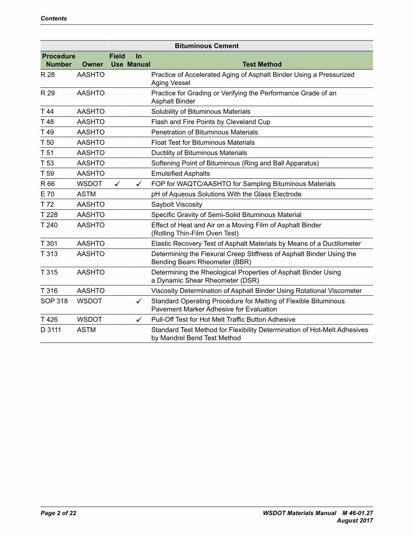
Contents
Page 2 of 22 WSDOT Materials Manual M 46-01.27 August 2017
Bituminous CementProcedure
Number OwnerField Use
In Manual Test Method
R 28 AASHTO Practice of Accelerated Aging of Asphalt Binder Using a Pressurized Aging Vessel
R 29 AASHTO Practice for Grading or Verifying the Performance Grade of an Asphalt Binder
T 44 AASHTO Solubility of Bituminous MaterialsT 48 AASHTO Flash and Fire Points by Cleveland CupT 49 AASHTO Penetration of Bituminous MaterialsT 50 AASHTO Float Test for Bituminous MaterialsT 51 AASHTO Ductility of Bituminous MaterialsT 53 AASHTO Softening Point of Bituminous (Ring and Ball Apparatus)T 59 AASHTO Emulsified AsphaltsR 66 WSDOT FOP for WAQTC/AASHTO for Sampling Bituminous MaterialsE 70 ASTM pH of Aqueous Solutions With the Glass ElectrodeT 72 AASHTO Saybolt ViscosityT 228 AASHTO Specific Gravity of Semi-Solid Bituminous MaterialT 240 AASHTO Effect of Heat and Air on a Moving Film of Asphalt Binder
(Rolling Thin-Film Oven Test)T 301 AASHTO Elastic Recovery Test of Asphalt Materials by Means of a DuctilometerT 313 AASHTO Determining the Flexural Creep Stiffness of Asphalt Binder Using the
Bending Beam Rheometer (BBR)T 315 AASHTO Determining the Rheological Properties of Asphalt Binder Using
a Dynamic Shear Rheometer (DSR)T 316 AASHTO Viscosity Determination of Asphalt Binder Using Rotational ViscometerSOP 318 WSDOT Standard Operating Procedure for Melting of Flexible Bituminous
Pavement Marker Adhesive for EvaluationT 426 WSDOT Pull-Off Test for Hot Melt Traffic Button AdhesiveD 3111 ASTM Standard Test Method for Flexibility Determination of Hot-Melt Adhesives
by Mandrel Bend Test Method
Contents
WSDOT Materials Manual M 46-01.27 Page 3 of 22 August 2017
Hot Mix AsphaltProcedure
Number OwnerField Use
In Manual Test Method
T 27/T 11 WSDOT FOP for WAQTC/AASHTO for Sieve Analysis of Fine and Coarse Aggregates
R 30 AASHTO Practice for Short and Long Term Aging of Hot Mix Asphalt (HMA)T 30 AASHTO Mechanical Analysis of Extracted AggregateR 47 AASHTO Standard Recommended Practice for Reducing Samples of Hot Mix
Asphalt (HMA) to Testing SizeR 79 AASHTO Vacuum Drying Compacted Asphalt SpecimensT 166 AASHTO Bulk Specific Gravity of Compacted Asphalt Mixtures Using Saturated
Surface-Dry SpecimensT 166 WSDOT FOP for AASHTO for Bulk Specific Gravity of Compacted Hot Mix
Asphalt Using Saturated Surface-Dry SpecimensT 168 AASHTO Sampling Bituminous Paving MixturesT 168 WSDOT FOP for WAQTC/AASHTO for Sampling of Hot Mix Asphalt
Paving MixturesT 209 AASHTO Theoretical Maximum Specific Gravity and Density of Hot Mix
Asphalt (HMA)T 209 WSDOT FOP for AASHTO for Theoretical Maximum Specific Gravity and Density
of Hot-Mix Asphalt Paving MixturesT 269 AASHTO Percent Air Void in Compacted Dense and Open Asphalt MixturesT 308 AASHTO Determining the Asphalt Binder Content of Hot Mix Asphalt (HMA) by the
Ignition MethodT 308 WSDOT FOP for AASHTO for Determining the Asphalt Binder Content of Hot Mix
Asphalt (HMA) by the Ignition MethodT 312 WSDOT FOP for AASHTO for Preparing Hot-Mix Asphalt (HMA) Specimens
by Means of the Superpave Gyratory CompactorT 324 AASHTO Standard Method of Test for Hamburg Wheel-Track Testing of Compacted
Hot Mix Asphalt (HMA)T 329 WSDOT FOP for AASHTO for Moisture Content of Asphalt (HMA) by Oven MethodT 331 WSDOT Bulk Specific Gravity (Gmb) and Density of Compacted Hot Mix Asphalt
(HMA) Using Automatic Vacuum Sealing MethodT 355 WSDOT In-Place Density of Asphalt Mixes Using the Nuclear
Moisture-Density GaugeT 712 WSDOT Standard Method of Reducing Hot Mix Asphalt Paving MixturesT 716 WSDOT Method of Random Sampling for Locations of Testing and Sampling SitesT 718 WSDOT Method of Test for Determining Stripping of Hot Mix AsphaltT 720 WSDOT Method of Test for Thickness Measurement of Hot Mix Asphalt
(HMA) CoresSOP 723 WSDOT Standard Operating Procedure for Submitting Hot Mix Asphalt
(HMA) Mix Designs for VerificationT 724 WSDOT Method of Preparation of Aggregate for Hot Mix Asphalt (HMA)
Mix DesignsT 726 WSDOT Mixing Procedure for Hot Mix Asphalt (HMA)SOP 728 WSDOT Standard Operating Procedure for Determining the Ignition Furnace
Calibration Factor (IFCF) for Hot Mix Asphalt (HMA)
Contents
Page 4 of 22 WSDOT Materials Manual M 46-01.27 August 2017
Hot Mix AsphaltProcedure
Number OwnerField Use
In Manual Test Method
SOP 729 WSDOT Standard Operating Procedure for Determination of the Moving Average of Theoretical Maximum Density (TMD) for HMA
SOP 730 WSDOT Standard Operating Procedure for Correlation of Nuclear Gauge Densities With Hot Mix Asphalt (HMA) Cores
SOP 731 WSDOT Standard Operating Procedure for Determining Volumetric Properties of Hot Mix Asphalt
SOP 732 WSDOT Standard Operating Procedure for Volumetric Design for Hot-Mix Asphalt (HMA)
SOP 733 WSDOT Standard Operating Procedure for Determination of Pavement Density Differentials Using the Nuclear Density Gauge
SOP 734 WSDOT Standard Operating Procedure for Sampling Hot Mix Asphalt After Compaction (Obtaining Cores)
SOP 735 WSDOT Standard Operating Procedure for Longitudinal Joint DensitySOP 736 WSDOT In-Place Density of Bituminous Mixes Using CoresSOP 737 Procedure for the Forensic Testing of HMA Field Cores D 6931 ASTM Standard Test Method for Indirect Tensile (IDT) Strength of Bituminous
Mixtures
Contents
WSDOT Materials Manual M 46-01.27 Page 5 of 22 August 2017
CementProcedure
Number OwnerField Use
In Manual Test Method
T 105 AASHTO Chemical Analysis of Hydraulic CementT 106 AASHTO Compressive Strength of Hydraulic Cement Mortars (Using 2-in. or
(50-mm) Cube Specimens)T 106 WSDOT FOP for AASHTO for Compressive Strength of Hydraulic Cement Mortars
(Using 2-in. or (50-mm) Cube Specimens)T 107 AASHTO Autoclave Expansion of Portland CementT 129 AASHTO Normal Consistency of Hydraulic CementT 131 AASHTO Time of Setting of Hydraulic Cement by Vicat NeedleT 133 AASHTO Density of Hydraulic CementT 137 AASHTO Air Content of Hydraulic Cement MortarT 153 AASHTO Fineness of Hydraulic Cement by Air Permeability ApparatusT 162 AASHTO Mechanical Mixing of Hydraulic Cement Pastes and Mortars of
Plastic ConsistencyT 260 AASHTO Sampling and Testing for Chloride Ion in Concrete and Concrete
Raw MaterialsT 303 AASHTO Accelerated Detection of Potentially Deleterious Expansion of Mortar Bars
Due to Alkali-Silica ReactionT 313 WSDOT Method of Test for Cement-Latex CompatibilityT 314 WSDOT Method of Test for Photovolt ReflectanceT 413 WSDOT Method of Test for Evaluating Waterproofing Effectiveness of Membrane
and Membrane-Pavement SystemsD 562 ASTM Standard Test Method for Consistency of Paints Measuring Krebs
Unit (KU) Viscosity Using a Stormer-Type ViscometerT 813 WSDOT Field Method of Fabrication of 2 in (50 mm) Cube Specimens
for Compressive Strength Testing of Grouts and MortarsT 814 WSDOT Method of Test for Water Retention Efficiency of Liquid Membrane-
Forming Compounds and Impermeable Sheet Materials for Curing Concrete
C 939 WSDOT FOP for ASTM for Flow of Grout for Preplaced-Aggregate Concrete (Flow Cone Method)
Contents
Page 6 of 22 WSDOT Materials Manual M 46-01.27 August 2017
ChemicalProcedure
Number OwnerField Use
In Manual Test Method
T 65 AASHTO Mass (Weight) of Coating on Iron and Steel Articles With Zinc or Zinc-Alloy Coatings
T 267 AASHTO Determination of Organic Content in Soils by Loss on IgnitionT 420 WSDOT Test Method for Determining the Maturity of Compost (Solvita Test)C 881 ASTM Standard Specification for Epoxy-Resin-Base Bonding Systems
for ConcreteC 882 ASTM Bond Strength (Diagonal Shear) (Checklist Only)C 1218 ASTM Standard Test Method for Water-Soluble Chloride in Mortar and ConcreteD 1429 ASTM Standard Test Methods for Specific Gravity of Water and BrineD 1475 ASTM Test Method for Consistency of Paints Test Method for Density of Paint,D 2628/ M 220
ASTM Test for High and Low Temperature Recovery of Elastomeric Joint Seals for Concrete Pavements
D 4758 ASTM Test Method for Nonvolatile Contents of LatexesD 5329 ASTM Standard Test Methods for Sealants and Fillers, Hot-Applied, for Joints
and Cracks in Asphaltic and Portland Cement Concrete PavementsD 7091 ASTM Nondestructive Measurement of Thickness of Nonmagnetic Coatings on
a Ferrous Base (Checklist Only)
Contents
WSDOT Materials Manual M 46-01.27 Page 7 of 22 August 2017
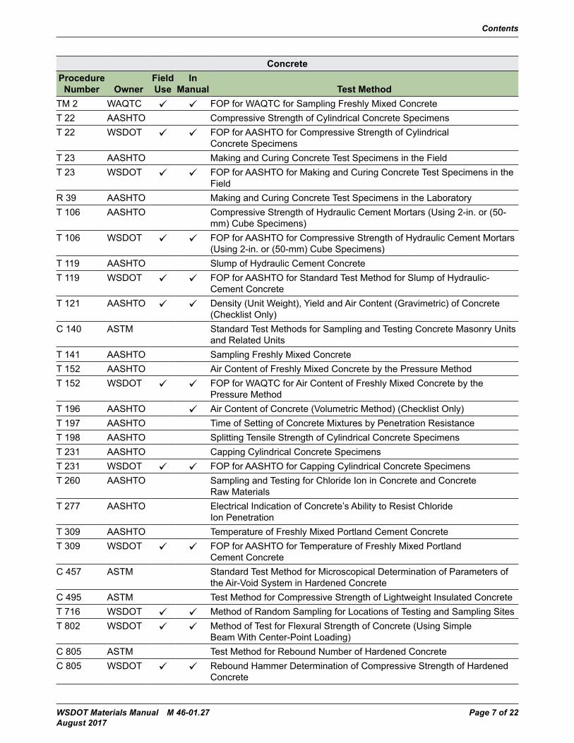
ConcreteProcedure
Number OwnerField Use
In Manual Test Method
TM 2 WAQTC FOP for WAQTC for Sampling Freshly Mixed ConcreteT 22 AASHTO Compressive Strength of Cylindrical Concrete SpecimensT 22 WSDOT FOP for AASHTO for Compressive Strength of Cylindrical
Concrete SpecimensT 23 AASHTO Making and Curing Concrete Test Specimens in the FieldT 23 WSDOT FOP for AASHTO for Making and Curing Concrete Test Specimens in the
FieldR 39 AASHTO Making and Curing Concrete Test Specimens in the LaboratoryT 106 AASHTO Compressive Strength of Hydraulic Cement Mortars (Using 2-in. or (50-
mm) Cube Specimens)T 106 WSDOT FOP for AASHTO for Compressive Strength of Hydraulic Cement Mortars
(Using 2-in. or (50-mm) Cube Specimens)T 119 AASHTO Slump of Hydraulic Cement ConcreteT 119 WSDOT FOP for AASHTO for Standard Test Method for Slump of Hydraulic-
Cement ConcreteT 121 AASHTO Density (Unit Weight), Yield and Air Content (Gravimetric) of Concrete
(Checklist Only)C 140 ASTM Standard Test Methods for Sampling and Testing Concrete Masonry Units
and Related UnitsT 141 AASHTO Sampling Freshly Mixed ConcreteT 152 AASHTO Air Content of Freshly Mixed Concrete by the Pressure MethodT 152 WSDOT FOP for WAQTC for Air Content of Freshly Mixed Concrete by the
Pressure MethodT 196 AASHTO Air Content of Concrete (Volumetric Method) (Checklist Only)T 197 AASHTO Time of Setting of Concrete Mixtures by Penetration ResistanceT 198 AASHTO Splitting Tensile Strength of Cylindrical Concrete SpecimensT 231 AASHTO Capping Cylindrical Concrete SpecimensT 231 WSDOT FOP for AASHTO for Capping Cylindrical Concrete SpecimensT 260 AASHTO Sampling and Testing for Chloride Ion in Concrete and Concrete
Raw MaterialsT 277 AASHTO Electrical Indication of Concrete’s Ability to Resist Chloride
Ion PenetrationT 309 AASHTO Temperature of Freshly Mixed Portland Cement ConcreteT 309 WSDOT FOP for AASHTO for Temperature of Freshly Mixed Portland
Cement ConcreteC 457 ASTM Standard Test Method for Microscopical Determination of Parameters of
the Air-Void System in Hardened ConcreteC 495 ASTM Test Method for Compressive Strength of Lightweight Insulated ConcreteT 716 WSDOT Method of Random Sampling for Locations of Testing and Sampling SitesT 802 WSDOT Method of Test for Flexural Strength of Concrete (Using Simple
Beam With Center-Point Loading)C 805 ASTM Test Method for Rebound Number of Hardened ConcreteC 805 WSDOT Rebound Hammer Determination of Compressive Strength of Hardened
Concrete
Contents
Page 8 of 22 WSDOT Materials Manual M 46-01.27 August 2017
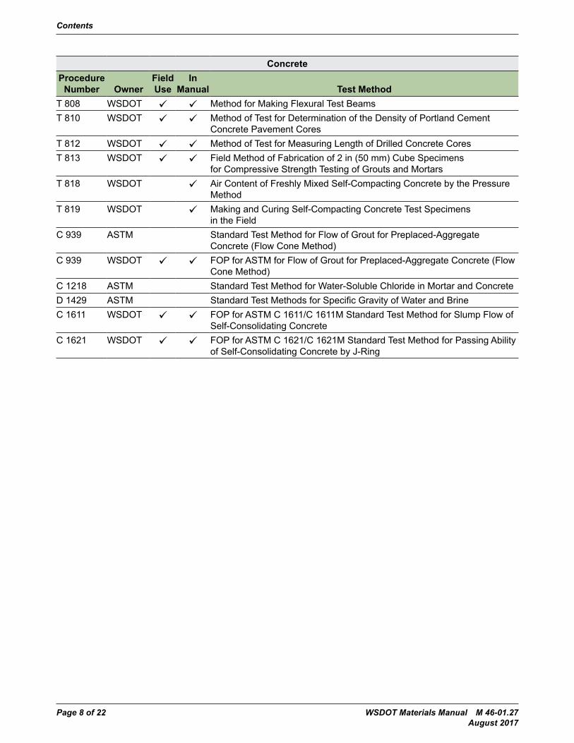
ConcreteProcedure
Number OwnerField Use
In Manual Test Method
T 808 WSDOT Method for Making Flexural Test BeamsT 810 WSDOT Method of Test for Determination of the Density of Portland Cement
Concrete Pavement CoresT 812 WSDOT Method of Test for Measuring Length of Drilled Concrete CoresT 813 WSDOT Field Method of Fabrication of 2 in (50 mm) Cube Specimens
for Compressive Strength Testing of Grouts and MortarsT 818 WSDOT Air Content of Freshly Mixed Self-Compacting Concrete by the Pressure
MethodT 819 WSDOT Making and Curing Self-Compacting Concrete Test Specimens
in the FieldC 939 ASTM Standard Test Method for Flow of Grout for Preplaced-Aggregate
Concrete (Flow Cone Method)C 939 WSDOT FOP for ASTM for Flow of Grout for Preplaced-Aggregate Concrete (Flow
Cone Method)C 1218 ASTM Standard Test Method for Water-Soluble Chloride in Mortar and ConcreteD 1429 ASTM Standard Test Methods for Specific Gravity of Water and BrineC 1611 WSDOT FOP for ASTM C 1611/C 1611M Standard Test Method for Slump Flow of
Self-Consolidating ConcreteC 1621 WSDOT FOP for ASTM C 1621/C 1621M Standard Test Method for Passing Ability
of Self-Consolidating Concrete by J-Ring
Contents
WSDOT Materials Manual M 46-01.27 Page 9 of 22 August 2017
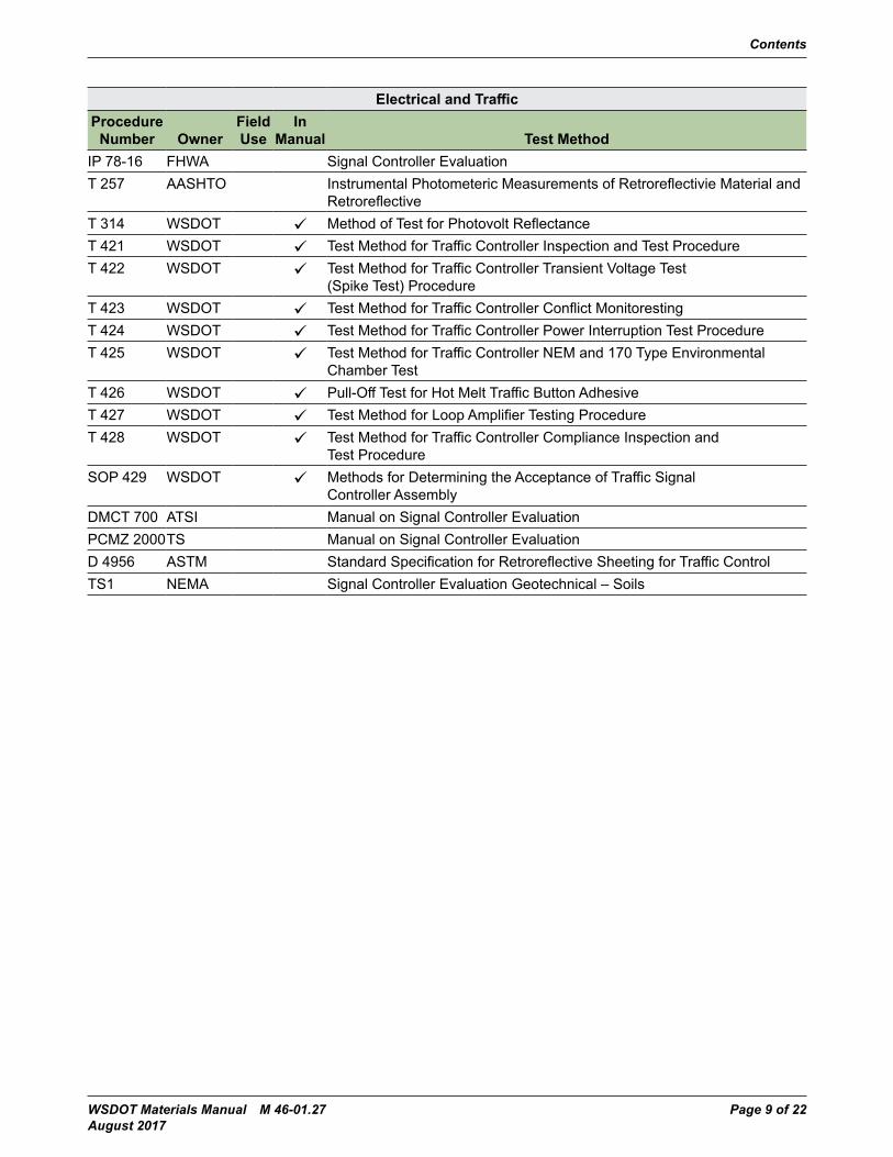
Electrical and TrafficProcedure
Number OwnerField Use
In Manual Test Method
IP 78-16 FHWA Signal Controller EvaluationT 257 AASHTO Instrumental Photometeric Measurements of Retroreflectivie Material and
RetroreflectiveT 314 WSDOT Method of Test for Photovolt ReflectanceT 421 WSDOT Test Method for Traffic Controller Inspection and Test ProcedureT 422 WSDOT Test Method for Traffic Controller Transient Voltage Test
(Spike Test) ProcedureT 423 WSDOT Test Method for Traffic Controller Conflict MonitorestingT 424 WSDOT Test Method for Traffic Controller Power Interruption Test ProcedureT 425 WSDOT Test Method for Traffic Controller NEM and 170 Type Environmental
Chamber TestT 426 WSDOT Pull-Off Test for Hot Melt Traffic Button AdhesiveT 427 WSDOT Test Method for Loop Amplifier Testing ProcedureT 428 WSDOT Test Method for Traffic Controller Compliance Inspection and
Test ProcedureSOP 429 WSDOT Methods for Determining the Acceptance of Traffic Signal
Controller AssemblyDMCT 700 ATSI Manual on Signal Controller EvaluationPCMZ 2000TS Manual on Signal Controller EvaluationD 4956 ASTM Standard Specification for Retroreflective Sheeting for Traffic ControlTS1 NEMA Signal Controller Evaluation Geotechnical – Soils
Contents
Page 10 of 22 WSDOT Materials Manual M 46-01.27 August 2017
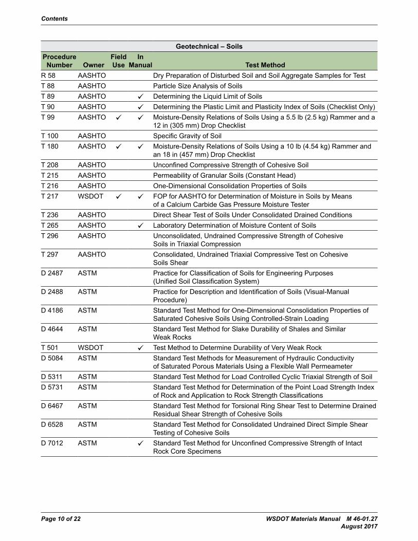
Geotechnical – SoilsProcedure
Number OwnerField Use
In Manual Test Method
R 58 AASHTO Dry Preparation of Disturbed Soil and Soil Aggregate Samples for TestT 88 AASHTO Particle Size Analysis of SoilsT 89 AASHTO Determining the Liquid Limit of SoilsT 90 AASHTO Determining the Plastic Limit and Plasticity Index of Soils (Checklist Only)T 99 AASHTO Moisture-Density Relations of Soils Using a 5.5 lb (2.5 kg) Rammer and a
12 in (305 mm) Drop ChecklistT 100 AASHTO Specific Gravity of SoilT 180 AASHTO Moisture-Density Relations of Soils Using a 10 lb (4.54 kg) Rammer and
an 18 in (457 mm) Drop ChecklistT 208 AASHTO Unconfined Compressive Strength of Cohesive SoilT 215 AASHTO Permeability of Granular Soils (Constant Head)T 216 AASHTO One-Dimensional Consolidation Properties of SoilsT 217 WSDOT FOP for AASHTO for Determination of Moisture in Soils by Means
of a Calcium Carbide Gas Pressure Moisture TesterT 236 AASHTO Direct Shear Test of Soils Under Consolidated Drained ConditionsT 265 AASHTO Laboratory Determination of Moisture Content of SoilsT 296 AASHTO Unconsolidated, Undrained Compressive Strength of Cohesive
Soils in Triaxial CompressionT 297 AASHTO Consolidated, Undrained Triaxial Compressive Test on Cohesive
Soils ShearD 2487 ASTM Practice for Classification of Soils for Engineering Purposes
(Unified Soil Classification System)D 2488 ASTM Practice for Description and Identification of Soils (Visual-Manual
Procedure)D 4186 ASTM Standard Test Method for One-Dimensional Consolidation Properties of
Saturated Cohesive Soils Using Controlled-Strain LoadingD 4644 ASTM Standard Test Method for Slake Durability of Shales and Similar
Weak RocksT 501 WSDOT Test Method to Determine Durability of Very Weak RockD 5084 ASTM Standard Test Methods for Measurement of Hydraulic Conductivity
of Saturated Porous Materials Using a Flexible Wall PermeameterD 5311 ASTM Standard Test Method for Load Controlled Cyclic Triaxial Strength of SoilD 5731 ASTM Standard Test Method for Determination of the Point Load Strength Index
of Rock and Application to Rock Strength ClassificationsD 6467 ASTM Standard Test Method for Torsional Ring Shear Test to Determine Drained
Residual Shear Strength of Cohesive SoilsD 6528 ASTM Standard Test Method for Consolidated Undrained Direct Simple Shear
Testing of Cohesive SoilsD 7012 ASTM Standard Test Method for Unconfined Compressive Strength of Intact
Rock Core Specimens

Contents
WSDOT Materials Manual M 46-01.27 Page 11 of 22 August 2017
Geotextile and SteelProcedure
Number OwnerField Use
In Manual Test Method
A 143 ASTM Standard Practice for Safeguarding Against Embrittlement of Hot-Dip Galvanized Structural Steel Products and Procedure for Detecting Embrittlement
T 244 AASHTO Mechanical Testing of Steel ProductsA 370 ASTM Standard Test Methods and Definitions for Mechanical Testing of
Steel ProductsF 606 ASTM Mechanical Properties: Steel FastenersT 914 WSDOT Practice for Sampling of Geosynthetic Material for TestingT 915 WSDOT Practice for Conditioning of Geotextiles for TestingT 923 WSDOT Thickness Measurement of GeotextilesT 925 WSDOT Standard Practice for Determination of Long-Term Strength for
Geosynthetic ReinforcementT 926 WSDOT Geogrid Brittleness TestD 1683 ASTM Sewen Seams (Geotextiles)D 4355 ASTM Standard Test Method for Deterioration of Geotextiles From Exposure
to Ultraviolet Light and Water (Xenon-Arc Type Apparatus)D 4491 ASTM Water Permeability (Geotextiles)D 4533 ASTM Tear Strength (Geotextiles)D 4354 ASTM Standard Practice for Sampling of Geosynthetics for TestingD 4595 ASTM Wide Width Breaking Load (Geotextiles)D 4632 ASTM Grab Breaking Load (Geotextiles)D 4751 ASTM Apparent Opening Size (Geotextiles)D 6241 ASTM Puncture (Geotextiles)
Contents
Page 12 of 22 WSDOT Materials Manual M 46-01.27 August 2017
PaintProcedure
Number OwnerField Use
In Manual Test Method
D 185 ASTM Standard Test Methods for Coarse Particles in Pigments, Pastes, and Paints
T 314 ASTM Method of Test for Photovolt ReflectanceD 562 ASTM Standard Test Method for Consistency of Paints Measuring Krebs
Unit (KU) Viscosity Using a Stormer-Type ViscometerD 1208 ASTM Method for Determination of Loss on IgnitionD 1210 ASTM Standard Test Method for Fineness of Dispersion of Pigment-Vehicle
Systems by Hegman-Type GageD 1475 ASTM Test Method for Density of Paint and Related ProductsD 2244 ASTM Standard Practice for Calculation of Color Tolerances and Color
Differences From Instrumentally Measured Color CoordinatesD 2369 ASTM Method for Determination of Volatile and Nonvolatile Content
(Ordinary Laboratory Oven)D 2371 ASTM Standard Test Method for Pigment Content of Solvent-Reducible Paints
(Centrifuge)D 2621 ASTM Standard Test Method for Infrared Identification of Vehicle Solids
From Solvent-Reducible PaintsD 2697 ASTM Standard Test Method for Volume Nonvolatile Matter in Clear or
Pigmented Coatings3011 FTMS Method for Determination of Condition in ContainerD 3723 ASTM Standard Test Method for Pigment Content of Water Emulsion Paints by
Temperature Ashing4053 FTMS Method for Determination of Nonvolatile Vehicle Content4061 FTMS Method for Determination of Drying Time (Oil-Based Paints)4122 FTMS Method for Determination of Hiding Power (Contrast Ratio)D 4505 ASTM Standard Specification for Preformed Plastic Pavement Marking Tape for
Extended Service Life Pavement Soils
Contents
WSDOT Materials Manual M 46-01.27 Page 13 of 22 August 2017
Pavement SoilsProcedure
Number OwnerField Use
In Manual Test Method
T 242 AASHTO Frictional Properties of Paved Surfaces Using a Full-Size TireT 272 AASHTO Family of Curves – One Point MethodT 272 WSDOT FOP for AASHTO for Family of Curves – One Point MethodT 307 AASHTO Determining the Resilient Modulus of Soils and Aggregate MaterialsT 310 WSDOT FOP for AASHTO for In-Place Density and Moisture Content of Soil and
Soil-Aggregate by Nuclear Methods (Shallow Depth)T 606 WSDOT Method of Test for Compaction Control of Granular MaterialsT 610 WSDOT Method of Test for the Capillary Rise of SoilsSOP 615 WSDOT Determination of the % Compaction for Embankment & Untreated
Surfacing Materials Using the Nuclear Moisture-Density GaugeT 807 WSDOT Method of Operation of California Profilograph and Evaluation of ProfilesD 4694 ASTM Test Method for Deflections With Falling-eight Type Impulse Load Device
Standard PracticeProcedure
Number OwnerField Use
In Manual Test Method
QC 1 WSDOT Standard Practice for Cement Producers/Importers/Distributors That Certify Portland Cement and Blended Hydraulic Cement
QC 2 WSDOT Standard Practice for Asphalt Suppliers That Certify Performance Graded and Emulsified Asphalts
QC 3 WSDOT Quality System Laboratory ReviewQC 4 WSDOT Standard Practice for Fly Ash Producers/Importers/Distributors
That Certify Fly AshQC 5 WSDOT Standard Practice for Ground Granulated Blast-Furnace Slag Producers/
Importers/Distributors That Certify Ground Granulated Blast-Furnace SlagQC 6 WSDOT Annual Prestressed Plant Review and Approval ProcessQC 7 WSDOT Annual Precast Plant Review and Approval ProcessQC 8 WSDOT Standard Practice for Approval of Hot Mix Asphalt Mix Designs for the
Qualified Products List
Contents
Page 14 of 22 WSDOT Materials Manual M 46-01.27 August 2017
Numerical OrderProcedure
Number OwnerField Use
In Manual Test Method
QC 1 WSDOT Standard Practice for Cement Producers/Importers/Distributors That Certify Portland Cement and Blended Hydraulic Cement
QC 2 WSDOT Standard Practice for Asphalt Suppliers That Certify Performance Graded and Emulsified Asphalts
QC 3 WSDOT Quality System Laboratory ReviewQC 4 WSDOT Standard Practice for Fly Ash Producers/Importers/Distributors
That Certify Fly AshQC 5 WSDOT Standard Practice for Ground Granulated Blast-Furnace Slag Producers/
Importers/Distributors That Certify Ground Granulated Blast-Furnace SlagQC 6 WSDOT Annual Prestressed Plant Review and Approval ProcessQC 7 WSDOT Annual Precast Plant Review and Approval ProcessQC 8 WSDOT Standard Practice for Approval of Hot Mix Asphalt Mix Designs for the
Qualified Products ListTS1 NEMA Signal Controller Evaluation Geotechnical – SoilsT 2 WSDOT FOP for AASHTO for Standard Practice for Sampling AggregatesTM 2 WAQTC FOP for WAQTC for Sampling Freshly Mixed ConcreteT 11 AASHTO Materials Finer Than 0.075 mm (No. 200) Sieve in Mineral Aggregates
by WashingE 18 ASTM Standard Test Methods for Rockwell Hardness of Metallic MaterialsT 19 AASHTO Bulk Density (“Unit Weight”) and Voids in Aggregate (Rodding Procedure
Only) (Checklist Only)T 21 AASHTO Organic Impurities in Fine Aggregates for ConcreteT 22 AASHTO Compressive Strength of Cylindrical Concrete SpecimensT 22 WSDOT FOP for AASHTO for Compressive Strength of Cylindrical
Concrete SpecimensT 23 AASHTO Making and Curing Concrete Test Specimens in the FieldT 23 WSDOT FOP for AASHTO for Making and Curing Concrete Test Specimens
in the FieldT 27 AASHTO Sieve Analysis of Fine and Coarse AggregatesT 27/T 11 WSDOT FOP for WAQTC/AASHTO for Sieve Analysis of Fine and
Coarse AggregatesR 28 AASHTO Practice of Accelerated Aging of Asphalt Binder Using a Pressurized
Aging VesselR 29 AASHTO Practice for Grading or Verifying the Performance Grade of an
Asphalt BinderR 30 AASHTO Practice for Short and Long Term Aging of Hot Mix Asphalt (HMA)T 30 AASHTO Mechanical Analysis of Extracted AggregateT 37 AASHTO Sieve Analysis of Mineral FillerR 39 AASHTO Making and curing Concrete Test Specimens in the LaboratoryT 44 AASHTO Solubility of Bituminous MaterialsR 47 AASHTO Standard Recommended Practice for Reducing Samples of Hot Mix
Asphalt (HMA) to Testing SizeT 48 AASHTO Flash and Fire Points by Cleveland CupT 49 AASHTO Penetration of Bituminous Materials
Contents
WSDOT Materials Manual M 46-01.27 Page 15 of 22 August 2017
Numerical OrderProcedure
Number OwnerField Use
In Manual Test Method
T 50 AASHTO Float Test for Bituminous MaterialsT 51 AASHTO Ductility of Bituminous MaterialsT 53 AASHTO Softening Point of Bituminous (Ring and Ball Apparatus)R 58 AASHTO Dry Preparation of Disturbed Soil and Soil Aggregate Samples for TestT 59 AASHTO Emulsified AsphaltsT 65 AASHTO Mass (Weight) of Coating on Iron and Steel Articles With Zinc or
Zinc-Alloy CoatingsR 66 WSDOT FOP for WAQTC/AASHTO for Sampling Bituminous MaterialsE 70 ASTM pH of Aqueous Solutions With the Glass ElectrodeT 72 AASHTO Saybolt ViscosityR 76 AASHTO Reducing Samples of Aggregate to Testing SizeR 76 WSDOT FOP for AASHTO for Reducing Samples of Aggregate to Testing SizeIP 78-16 FHWA Signal Controller EvaluationR 79 AASHTO Vacuum Drying Compacted Asphalt Specimens T 84 AASHTO Specific Gravity and Absorption of Fine AggregatesT 85 AASHTO Specific Gravity and Absorption of Coarse AggregatesT 88 AASHTO Particle Size Analysis of SoilsT 89 AASHTO Determining the Liquid Limit of SoilsT 90 AASHTO Determining the Plastic Limit and Plasticity Index of Soils (Checklist Only)T 96 AASHTO Resistance to Degradation of Small-Size Coarse Aggregate by Abrasion
and Impact in the Los Angeles MachineT 99 AASHTO Moisture-Density Relations of Soils Using a 5.5 lb (2.5 kg) Rammer and a
12 in (305 mm) Drop ChecklistT 100 AASHTO Specific Gravity of SoilT 105 AASHTO Chemical Analysis of Hydraulic CementT 106 AASHTO Compressive Strength of Hydraulic Cement Mortars (Using 2-in. or (50-
mm) Cube Specimens)T 106 WSDOT FOP for AASHTO for Compressive Strength of Hydraulic Cement Mortars
(Using 2-in. or (50-mm) Cube Specimens)T 107 AASHTO Autoclave Expansion of Hydraulic CementT 112 AASHTO Clay Lumps and Friable Particles in AggregateT 113 WSDOT Method of Test for Determination of Degradation ValueT 119 AASHTO Slump of Hydraulic Cement ConcreteT 119 WSDOT FOP for AASHTO for Standard Test Method for Slump of Hydraulic-
Cement ConcreteT 121 AASHTO Density (Unit Weight), Yield and Air Content (Gravimetric) of Concrete
(Checklist Only)T 123 WSDOT Method of Test for Bark MulchT 125 WSDOT Determination of Fiber Length Percentages in Wood Strand MulchT 126 WSDOT Determination of Fiber Length Percentages in Hydraulically-Applied
Erosion Control Products T 127 WSDOT Preparation of Leachate Sample for Testing Toxicity of HECP EffluentSOP 128 WSDOT Sampling for Aggregate Source Approval
Contents
Page 16 of 22 WSDOT Materials Manual M 46-01.27 August 2017
Numerical OrderProcedure
Number OwnerField Use
In Manual Test Method
T 129 AASHTO Normal Consistency of Hydraulic CementT 131 AASHTO Time of Setting of Hydraulic Cement by Vicat NeedleT 133 AASHTO Density of Hydraulic CementT 137 AASHTO Air Content of Hydraulic Cement MortarC 140 ASTM Standard Test Methods for Sampling and Testing Concrete Masonry Units
and Related UnitsT 141 AASHTO Sampling Freshly Mixed ConcreteA 143 ASTM Standard Practice for Safeguarding Against Embrittlement of
Hot-Dip Galvanized Structural Steel Products and Procedure for Detecting Embrittlement
T 152 AASHTO Air Content of Freshly Mixed Concrete by the Pressure MethodT 152 WSDOT FOP for WAQTC for Air Content of Freshly Mixed Concrete by the
Pressure MethodT 153 AASHTO Fineness of Hydraulic Cement by Air Permeability ApparatusT 162 AASHTO Mechanical Mixing of Hydraulic Cement Pastes and Mortars of
Plastic ConsistencyT 166 AASHTO Bulk Specific Gravity of Compacted Hot Mix Asphalt (HMA) Using
Saturated Surface-Dry SpecimensT 166 WSDOT FOP for AASHTO for Bulk Specific Gravity of Compacted Hot Mix
Asphalt Using Saturated Surface-Dry SpecimensT 168 AASHTO Sampling Bituminous Paving MixturesT 168 WSDOT FOP for WAQTC/AASHTO for Sampling of Hot Mix Asphalt
Paving MixturesT 176 AASHTO Plastic Fines in Graded Aggregates and Soils by Use of the
Sand Equivalent TestT 176 WSDOT FOP for AASHTO for Plastic Fines in Graded Aggregates and
Soils by Use of the Sand Equivalent TestT 180 AASHTO Moisture-Density Relations of Soils Using a 10 lb (4.54 kg) Rammer and
an 18 in (457 mm) Drop ChecklistD 185 ASTM Standard Test Methods for Coarse Particles in Pigments, Pastes,
and PaintsT 196 AASHTO Air Content of Concrete (Volumetric Method) (Checklist Only)T 197 AASHTO Time of Setting of Concrete Mixtures by Penetration ResistanceT 198 AASHTO Splitting Tensile Strength of Cylindrical Concrete SpecimensT 208 AASHTO Unconfined Compressive Strength of Cohesive SoilT 209 AASHTO Theoretical Maximum Specific Gravity and Density of Hot Mix
Asphalt (HMA)T 209 WSDOT FOP for AASHTO for Theoretical Maximum Specific Gravity and Density
of Hot-Mix Asphalt Paving MixturesT 215 AASHTO Permeability of Granular Soils (Constant Head)T 216 AASHTO One-Dimensional Consolidation Properties of SoilsT 217 WSDOT FOP for AASHTO for Determination of Moisture in Soils by Means
of a Calcium Carbide Gas Pressure Moisture TesterT 228 AASHTO Specific Gravity of Semi-Solid Bituminous Material
Contents
WSDOT Materials Manual M 46-01.27 Page 17 of 22 August 2017
Numerical OrderProcedure
Number OwnerField Use
In Manual Test Method
T 231 AASHTO Capping Cylindrical Concrete SpecimensT 231 WSDOT FOP for AASHTO for Capping Cylindrical Concrete SpecimensT 236 AASHTO Direct Shear test of Soils Under Consolidated Drained ConditionsT 240 AASHTO Effect of Heat and Air on a Moving Film of Asphalt Binder
(Rolling Thin-Film Oven Test)T 242 AASHTO Frictional Properties of Paved Surfaces Using a Full-Size TireT 244 AASHTO Mechanical Testing of Steel ProductsT 255 AASHTO Total Evaporable Moisture Content of Aggregate by DryingT 255 WSDOT FOP for AASHTO for Total Evaporable Moisture Content of Aggregate by
DryingT 257 AASHTO Instrumental Photometeric Measurements of Retroreflectivie Material and
RetroreflectiveT 260 AASHTO Sampling and Testing for Chloride Ion in Concrete and Concrete
Raw MaterialsT 265 AASHTO Laboratory Determination of Moisture Content of SoilsT 267 AASHTO Determination of Organic Content in Soils by Loss on IgnitionT 269 AASHTO Percent Air Void in Compacted Dense and Open Asphalt MixturesT 272 AASHTO Family of Curves – One Point MethodT 272 WSDOT FOP for AASHTO for Family of Curves – One Point MethodT 277 AASHTO Electrical Indication of Concrete’s Ability to Resist Chloride
Ion PenetrationT 288 AASHTO Determining Minimum Laboratory Soil Resistivity (Checklist Only)T 289 AASHTO Determining pH of Soil for Use in CorrosionT 296 AASHTO Unconsolidated, Undrained Compressive Strength of Cohesive Soils
in Triaxial CompressionT 297 AASHTO Consolidated, Undrained Triaxial Compressive Test on Cohesive
Soils ShearT 301 AASHTO Elastic Recovery Test of Asphalt Materials by Means of a DuctilometerT 303 AASHTO Accelerated Detection of Potentially Deleterious Expansion of Mortar Bars
Due to Alkali-Silica ReactionT 304 WSDOT FOP for AASHTO for Uncompacted Void Content of Fine AggregateT 307 AASHTO Determining the Resilient Modulus of Soils and Aggregate MaterialsT 308 AASHTO Determining the Asphalt Binder Content of Hot Mix Asphalt (HMA) by the
Ignition MethodT 308 WSDOT FOP for AASHTO for Determining the Asphalt Binder Content of Hot Mix
Asphalt (HMA) by the Ignition MethodT 309 AASHTO Temperature of Freshly Mixed Hydraulic Cement ConcreteT 309 WSDOT FOP for AASHTO for Temperature of Freshly Mixed Portland
Cement ConcreteT 310 WSDOT FOP for AASHTO for In-Place Density and Moisture Content of Soil and
Soil-Aggregate by Nuclear Methods (Shallow Depth)T 312 WSDOT FOP for AASHTO for Preparing Hot-Mix Asphalt (HMA) Specimens
by Means of the Superpave Gyratory CompactorT 313 AASHTO Determining the Flexural Creep Stiffness of Asphalt Binder Using
the Bending Beam Rheometer (BBR)
Contents
Page 18 of 22 WSDOT Materials Manual M 46-01.27 August 2017
Numerical OrderProcedure
Number OwnerField Use
In Manual Test Method
T 313 WSDOT Method of Test for Cement-Latex CompatibilityT 314 WSDOT Method of Test for Photovolt ReflectanceT 315 AASHTO Determining the Rheological Properties of Asphalt Binder Using
a Dynamic Shear Rheometer (DSR)T 316 AASHTO Viscosity Determination of Asphalt Binder Using Rotational ViscometerSOP 318 WSDOT Standard Operating Procedure for Melting of Flexible Bituminous
Pavement Marker Adhesive for EvaluationT 324 AASHTO Standard Method of Test for Hamburg Wheel-Track Testing of Compacted
Hot Mix Asphalt (HMA)T 329 WSDOT FOP for AASHTO for Moisture Content of Asphalt (HMA) by Oven MethodT 331 WSDOT Bulk Specific Gravity (Gmb) and Density of Compacted Hot Mix Asphalt
(HMA) Using Automatic Vacuum Sealing MethodT 335 AASHTO Determining the Percentage of Fracture in Coarse AggregateT 335 WSDOT FOP for AASHTO for Determining the Percentage of Fracture in Coarse
AggregateT 355 WSDOT In-Place Density of Asphalt Mixes Using the Nuclear
Moisture-Density GaugeA 370 ASTM Standard Test Methods and Definitions for Mechanical Testing
of Steel ProductsT 413 WSDOT Method of Test for Evaluating Waterproofing Efectiveness of Membrane
and Membrane-Pavement SystemsT 417 WSDOT Method of Test for Determining Minimum Resistivily and pH of
Soil and WaterT 420 WSDOT Test Method for Determining the Maturity of Compost (Solvita Test)T 421 WSDOT Test Method for Traffic Controller Inspection and Test ProcedureT 422 WSDOT Test Method for Traffic Controller Transient Voltage Test
(Spike Test) ProcedureT 423 WSDOT Test Method for Traffic Controller Conflict MonitorestingT 424 WSDOT Test Method for Traffic Controller Power Interruption Test ProcedureT 425 WSDOT Test Method for Traffic Controller NEM and 170 Type Environmental
Chamber TestT 426 WSDOT Pull-Off Test for Hot Melt Traffic Button AdhesiveT 427 WSDOT Test Method for Loop Amplifier Testing ProcedureT 428 WSDOT Test Method for Traffic Controller Compliance Inspection and
Test ProcedureSOP 429 WSDOT Methods for Determining the Acceptance of Traffic Signal
Controller AssemblyT 432 WSDOT Flexibility Test for Hot-Melt AdhesivesC 457 ASTM Standard Test Method for Microscopical Determination of Parameters of
the Air-Void System in Hardened ConcreteC 495 ASTM Test Method for Compressive Strength of Lightweight Insulated ConcreteT 501 WSDOT Test Method to Determine Durability of Very Weak RockD 562 ASTM Standard Test Method for Consistency of Paints Measuring Krebs
Unit (KU) Viscosity Using a Stormer-Type Viscometer
Contents
WSDOT Materials Manual M 46-01.27 Page 19 of 22 August 2017
Numerical OrderProcedure
Number OwnerField Use
In Manual Test Method
F 606 ASTM Test Methods for Determining the Mechanical Properties of Externally and Internally Threaded Fasteners, Washers, Direct Tension Indicators, and Rivets
T 606 WSDOT Method of Test for Compaction Control of Granular MaterialsT 610 WSDOT Method of Test for the Capillary Rise of SoilsSOP 615 WSDOT Determination of the % Compaction for Embankment and Untreated
Surfacing Materials Using the Nuclear Moisture-Density GaugeDMCT 700 ATSI Manual on Signal Controller EvaluationT 712 WSDOT Standard Method of Reducing Hot Mix Asphalt Paving MixturesT 716 WSDOT Method of Random Sampling for Locations of Testing and Sampling SitesT 718 WSDOT Method of Test for Determining Stripping of Hot Mix AsphaltT 720 WSDOT Method of Test for Thickness Measurement of Hot Mix Asphalt
(HMA) CoresSOP 723 WSDOT Standard Operating Procedure for Submitting Hot Mix Asphalt
(HMA) Mix Designs for VerificationT 724 WSDOT Method of Preparation of Aggregate for Hot Mix Asphalt (HMA)
Mix DesignsT 726 WSDOT Mixing Procedure for Hot Mix Asphalt (HMA)SOP 728 WSDOT Standard Operating Procedure for Determining the Ignition Furnace
Calibration Factor (IFCF) for Hot Mix Asphalt (HMA)SOP 729 WSDOT Standard Operating Procedure for Determination of the Moving Average
of Theoretical Maximum Density (TMD) for HMASOP 730 WSDOT Standard Operating Procedure for Correlation of Nuclear Gauge Densities
With Hot Mix Asphalt (HMA) CoresSOP 731 WSDOT Standard Operating Procedure for Determining Volumetric Properties of
Hot Mix AsphaltSOP 732 WSDOT Standard Operating Procedure for Volumetric Design for Hot-Mix Asphalt
(HMA)SOP 733 WSDOT Standard Operating Procedure for Determination of Pavement
Density Differentials Using the Nuclear Density GaugeSOP 734 WSDOT Standard Operating Procedure for Sampling Hot Mix Asphalt
After Compaction (Obtaining Cores)SOP 735 WSDOT Standard Operating Procedure for Longitudinal Joint DensitySOP 736 WSDOT In-Place Density of Bituminous Mixes Using CoresSOP 737 Procedure for the Forensic Testing of HMA Field Cores T 802 WSDOT Method of Test for Flexural Strength of Concrete (Using Simple
Beam With Center-Point Loading)C 805 ASTM Test Method for Rebound Number of Hardened ConcreteC 805 WSDOT Rebound Hammer Determination of Compressive Strength of Hardened
ConcreteT 807 WSDOT Method of Operation of California Profilograph and Evaluation of ProfilesT 808 WSDOT Method for Making Flexural Test BeamsT 810 WSDOT Method of Test for Determination of the Density of Portland Cement
Concrete Pavement Cores
Contents
Page 20 of 22 WSDOT Materials Manual M 46-01.27 August 2017
Numerical OrderProcedure
Number OwnerField Use
In Manual Test Method
T 812 WSDOT Method of Test for Measuring Length of Drilled Concrete CoresT 813 WSDOT Field Method of Fabrication of 2 in (50 mm) Cube Specimens
for Compressive Strength Testing of Grouts and MortarsT 814 WSDOT Method of Test for Water Retention Efficiency of Liquid Membrane-
Forming Compounds and Impermeable Sheet Materials for Curing Concrete
T 818 WSDOT Air Content of Freshly Mixed Self-Compacting Concrete by the Pressure Method
T 819 WSDOT Making and Curing Self-Compacting Concrete Test Specimens in the Field
C 881 ASTM Standard Specification for Epoxy-Resin-Base Bonding Systems for Concrete
C 882 ASTM Bond Strength (Diagonal Shear) (Checklist Only)T 914 WSDOT Practice for Sampling of Geosynthetic Material for TestingT 915 WSDOT Practice for Conditioning of Geotextiles for TestingT 923 WSDOT Thickness Measurement of GeotextilesT 925 WSDOT Standard Practice for Determination of Long-Term Strength for
Geosynthetic ReinforcementT 926 WSDOT Geogrid Brittleness TestC 939 ASTM Standard Test Method for Flow of Grout for Preplaced-Aggregate
Concrete (Flow Cone Method)C 939 WSDOT FOP for ASTM for Flow of Grout for Preplaced-Aggregate Concrete (Flow
Cone Method)D 1208 ASTM Test Methods for Common Properties of Certain Pigments
(Loss on Ignition)D 1210 ASTM Standard Test Method for Fineness of Dispersion of Pigment-Vehicle
Systems by Hegman-Type GageC 1218 ASTM Standard Test Method for Water-Soluble Chloride in Mortar and ConcreteD 1429 ASTM Standard Test Methods for Specific Gravity of Water and BrineC 1437 ASTM Standard Test Method for Flow of Hydraulic Cement MortarD 1475 ASTM Test Method for Consistency of Paints Test Method for Density of Paint,
Varnish, Lacquer, and Related ProductsC 1611 WSDOT FOP for ASTM C 1611/C 1611M Standard Test Method for Slump Flow of
Self-Consolidating ConcreteC 1621 WSDOT FOP for ASTM C 1621/C 1621M Standard Test Method for Passing Ability
of Self-Consolidating Concrete by J-RingD 1683 ASTM Standard Test Method for Failure in Sewn Seams of Woven
Apparel FabricsPCMZ 2000TS Manual on Signal Controller EvaluationD 2240 ASTM Standard Test Method for Rubber Property – Durometer HardnessD 2244 ASTM Standard Practice for Calculation of Color Tolerances and Color
Differences From Instrumentally Measured Color CoordinatesD 2369 ASTM Test Method for Volatile Content of Coatings (Ordinary Laboratory Oven)
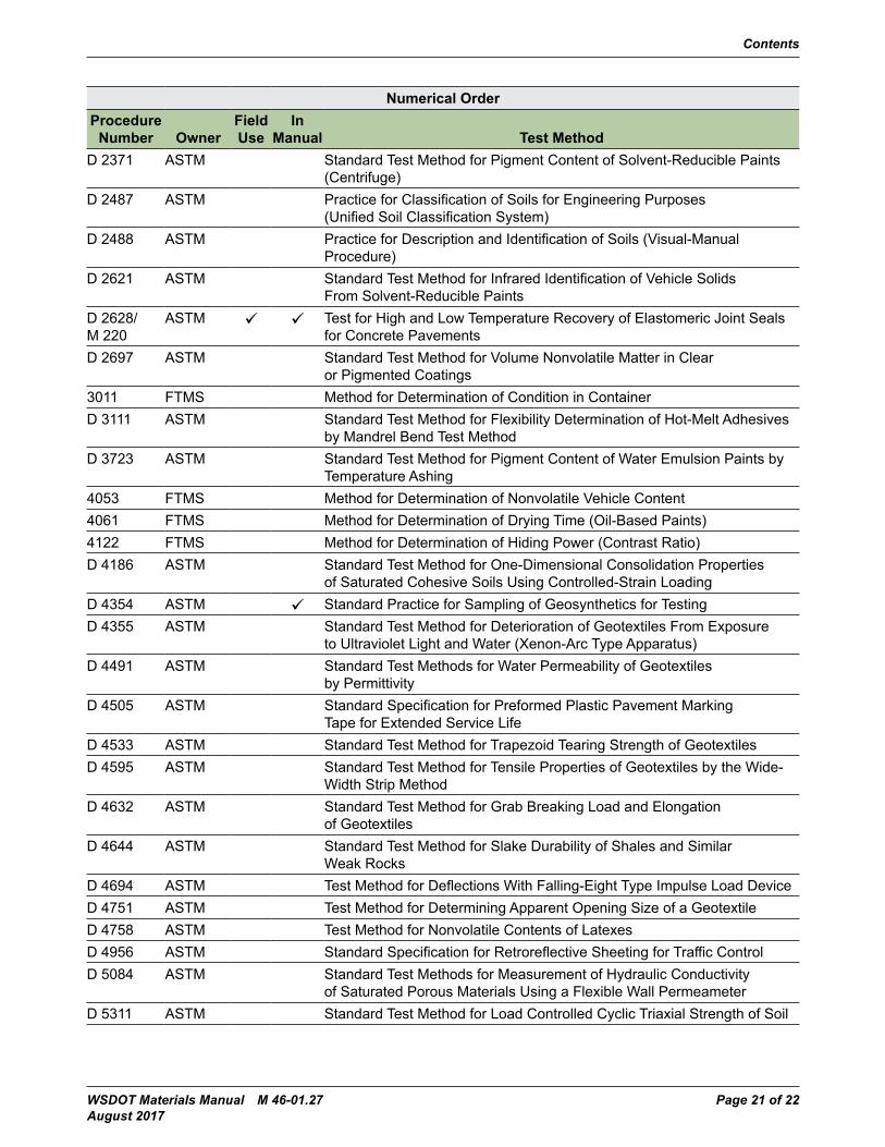
Contents
WSDOT Materials Manual M 46-01.27 Page 21 of 22 August 2017
Numerical OrderProcedure
Number OwnerField Use
In Manual Test Method
D 2371 ASTM Standard Test Method for Pigment Content of Solvent-Reducible Paints (Centrifuge)
D 2487 ASTM Practice for Classification of Soils for Engineering Purposes(Unified Soil Classification System)
D 2488 ASTM Practice for Description and Identification of Soils (Visual-Manual Procedure)
D 2621 ASTM Standard Test Method for Infrared Identification of Vehicle Solids From Solvent-Reducible Paints
D 2628/ M 220
ASTM Test for High and Low Temperature Recovery of Elastomeric Joint Seals for Concrete Pavements
D 2697 ASTM Standard Test Method for Volume Nonvolatile Matter in Clear or Pigmented Coatings
3011 FTMS Method for Determination of Condition in ContainerD 3111 ASTM Standard Test Method for Flexibility Determination of Hot-Melt Adhesives
by Mandrel Bend Test MethodD 3723 ASTM Standard Test Method for Pigment Content of Water Emulsion Paints by
Temperature Ashing4053 FTMS Method for Determination of Nonvolatile Vehicle Content4061 FTMS Method for Determination of Drying Time (Oil-Based Paints)4122 FTMS Method for Determination of Hiding Power (Contrast Ratio)D 4186 ASTM Standard Test Method for One-Dimensional Consolidation Properties
of Saturated Cohesive Soils Using Controlled-Strain LoadingD 4354 ASTM Standard Practice for Sampling of Geosynthetics for TestingD 4355 ASTM Standard Test Method for Deterioration of Geotextiles From Exposure
to Ultraviolet Light and Water (Xenon-Arc Type Apparatus)D 4491 ASTM Standard Test Methods for Water Permeability of Geotextiles
by Permittivity D 4505 ASTM Standard Specification for Preformed Plastic Pavement Marking
Tape for Extended Service LifeD 4533 ASTM Standard Test Method for Trapezoid Tearing Strength of GeotextilesD 4595 ASTM Standard Test Method for Tensile Properties of Geotextiles by the Wide-
Width Strip MethodD 4632 ASTM Standard Test Method for Grab Breaking Load and Elongation
of GeotextilesD 4644 ASTM Standard Test Method for Slake Durability of Shales and Similar
Weak RocksD 4694 ASTM Test Method for Deflections With Falling-Eight Type Impulse Load DeviceD 4751 ASTM Test Method for Determining Apparent Opening Size of a GeotextileD 4758 ASTM Test Method for Nonvolatile Contents of LatexesD 4956 ASTM Standard Specification for Retroreflective Sheeting for Traffic ControlD 5084 ASTM Standard Test Methods for Measurement of Hydraulic Conductivity
of Saturated Porous Materials Using a Flexible Wall PermeameterD 5311 ASTM Standard Test Method for Load Controlled Cyclic Triaxial Strength of Soil
Contents
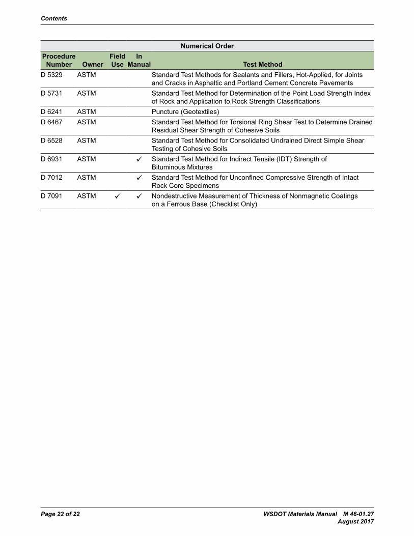
Page 22 of 22 WSDOT Materials Manual M 46-01.27 August 2017
Numerical OrderProcedure
Number OwnerField Use
In Manual Test Method
D 5329 ASTM Standard Test Methods for Sealants and Fillers, Hot-Applied, for Joints and Cracks in Asphaltic and Portland Cement Concrete Pavements
D 5731 ASTM Standard Test Method for Determination of the Point Load Strength Index of Rock and Application to Rock Strength Classifications
D 6241 ASTM Puncture (Geotextiles)D 6467 ASTM Standard Test Method for Torsional Ring Shear Test to Determine Drained
Residual Shear Strength of Cohesive SoilsD 6528 ASTM Standard Test Method for Consolidated Undrained Direct Simple Shear
Testing of Cohesive SoilsD 6931 ASTM Standard Test Method for Indirect Tensile (IDT) Strength of
Bituminous MixturesD 7012 ASTM Standard Test Method for Unconfined Compressive Strength of Intact
Rock Core SpecimensD 7091 ASTM Nondestructive Measurement of Thickness of Nonmagnetic Coatings
on a Ferrous Base (Checklist Only)
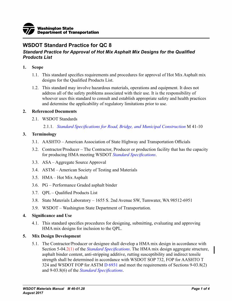
WSDOT Materials Manual M 46-01.28 Page 1 of 4 August 2017
WSDOT Standard Practice for QC 8 Standard Practice for Approval of Hot Mix Asphalt Mix Designs for the Qualified Products List
1. Scope
1.1. ThisstandardspecifiesrequirementsandproceduresforapprovalofHotMixAsphaltmixdesignsfortheQualifiedProductsList.
1.2. This standard may involve hazardous materials, operations and equipment. It does not address all of the safety problems associated with their use. It is the responsibility of whoever uses this standard to consult and establish appropriate safety and health practices and determine the applicability of regulatory limitations prior to use.
2. Referenced Documents
2.1. WSDOT Standards
2.1.1. Standard Specifications for Road, Bridge, and Municipal Construction M 41-10
3. Terminology
3.1. AASHTO–AmericanAssociationofStateHighwayandTransportationOfficials
3.2. Contractor/Producer–TheContractor,ProducerorproductionfacilitythathasthecapacityforproducingHMAmeetingWSDOTStandard Specifications.
3.3. ASA–AggregateSourceApproval
3.4. ASTM–AmericanSocietyofTestingandMaterials
3.5. HMA–HotMixAsphalt
3.6. PG–PerformanceGradedasphaltbinder
3.7. QPL–QualifiedProductsList
3.8. StateMaterialsLaboratory–1655S.2ndAvenueSW,Tumwater,WA98512-6951
3.9. WSDOT–WashingtonStateDepartmentofTransportation.
4. SignificanceandUse
4.1. Thisstandardspecifiesproceduresfordesigning,submitting,evaluatingandapprovingHMAmixdesignsforinclusiontotheQPL.
5. Mix Design Development
5.1. TheContractor/ProducerordesigneeshalldevelopaHMAmixdesigninaccordancewithSection 5-04.2(1) of the Standard Specifications.TheHMAmixdesignaggregatestructure,asphalt binder content, anti-stripping additive, rutting susceptibility and indirect tensile strengthshallbedeterminedinaccordancewithWSDOTSOP732,FOPforAASHTOT324 and WSDOT FOP for ASTM D 6931 and meet the requirements of Sections 9-03.8(2) and 9-03.8(6) of the Standard Specifications.
QC 8 Standard Practice for Approval of Hot Mix Asphalt Mix Designs for the Qualified Products List
Page 2 of 4 WSDOT Materials Manual M 46-01.28 August 2017
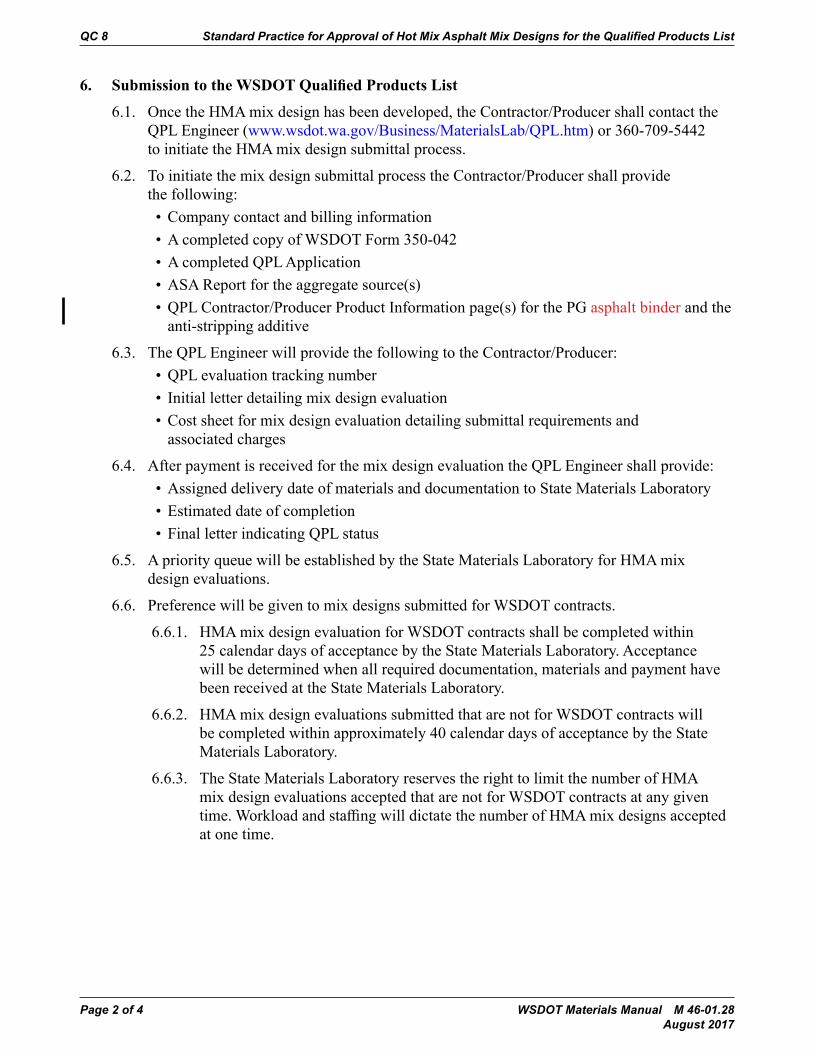
6. SubmissiontotheWSDOTQualifiedProductsList
6.1. OncetheHMAmixdesignhasbeendeveloped,theContractor/ProducershallcontacttheQPL Engineer (www.wsdot.wa.gov/Business/MaterialsLab/QPL.htm) or 360-709-5442 toinitiatetheHMAmixdesignsubmittalprocess.
6.2. To initiate the mix design submittal process the Contractor/Producer shall provide the following:• Company contact and billing information• A completed copy of WSDOT Form 350-042 • A completed QPL Application• ASA Report for the aggregate source(s)• QPL Contractor/Producer Product Information page(s) for the PG asphalt binder and the
anti-stripping additive
6.3. The QPL Engineer will provide the following to the Contractor/Producer:• QPL evaluation tracking number• Initial letter detailing mix design evaluation• Cost sheet for mix design evaluation detailing submittal requirements and
associated charges
6.4. After payment is received for the mix design evaluation the QPL Engineer shall provide:• Assigned delivery date of materials and documentation to State Materials Laboratory• Estimated date of completion• Final letter indicating QPL status
6.5. ApriorityqueuewillbeestablishedbytheStateMaterialsLaboratoryforHMAmixdesign evaluations.
6.6. Preference will be given to mix designs submitted for WSDOT contracts.
6.6.1. HMAmixdesignevaluationforWSDOTcontractsshallbecompletedwithin25 calendar days of acceptance by the State Materials Laboratory. Acceptance will be determined when all required documentation, materials and payment have been received at the State Materials Laboratory.
6.6.2. HMAmixdesignevaluationssubmittedthatarenotforWSDOTcontractswillbe completed within approximately 40 calendar days of acceptance by the State Materials Laboratory.
6.6.3. TheStateMaterialsLaboratoryreservestherighttolimitthenumberofHMAmix design evaluations accepted that are not for WSDOT contracts at any given time.WorkloadandstaffingwilldictatethenumberofHMAmixdesignsacceptedat one time.

Standard Practice for Approval of Hot Mix Asphalt Mix Designs for the Qualified Products List QC 8
WSDOT Materials Manual M 46-01.28 Page 3 of 4 August 2017
7. MixDesignEvaluation
7.1. TheHMAmixdesignsubmittedbytheContractor/Producerwillbeevaluatedbythe State Materials Laboratory in accordance with Section 9-03.8(2) and 9-03.8(6) of the Standard Specifications.
7.2. HMAmixdesignswillbeplacedontheQPLprovidedtheymeettherequirementsofSection 9-03.8(2) and 9-03.8(6) of the Standard Specifications.
7.2.1. Voids in Mineral Aggregate (VMA) must be within 1.5% of the minimum specificationinaccordancewithSection9-03.8(2)oftheStandard Specifications fortheclassofHMAevaluated.
7.2.2. %GmmatNdesignmustbewithin1.5%ofthespecificationinSection9-03.8(2)of the Standard SpecificationsfortheclassofHMAevaluated.
7.2.3. Voids Filled with Asphalt (VFA) in Section 9-03.8(2) will not be part of the mix design evaluation.
7.3. A mix design that fails to meet the requirements listed in Section 7.2, 7.2.1 and 7.2.2 will not be accepted or placed on the QPL.
7.4. Adjustments to mix designs will not be allowed once they have been evaluated.
7.5. The Contractor/Producer will be issued a QPL mix design record providing the mix design is in compliance with Section 9 of this Standard Practice.
7.6. TheQPLlistingforHMAmixdesignswillshowthefollowinginformation:• Company name•HMAClass• Aggregate Source(s)• PG Grade• PG Supplier• Anti-stripping additive brand and quantity (if applicable)
8. ReferencingMixDesignsFromTheQPL
8.1. RequestsforreferenceHMAmixdesignsfornonWSDOTprojectswillbecompletedon WSDOT Form 350-041 and emailed to [email protected].
8.2. ReferenceHMAmixdesignreportswillbeissuedfornewmixdesignsonactiveandawarded WSDOT contracts once accepted and placed on the QPL.
8.3. ReferenceHMAmixdesignreportswillbeissuedforcurrentmixdesignsonactiveandawardedWSDOTcontractsprovidedtheHMAproductionhistoryisincompliancewithStandard Specifications Section 5-04.3(11)D.
QC 8 Standard Practice for Approval of Hot Mix Asphalt Mix Designs for the Qualified Products List
Page 4 of 4 WSDOT Materials Manual M 46-01.28 August 2017
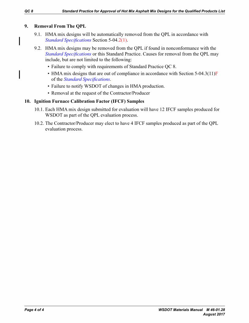
9. RemovalFromTheQPL
9.1. HMAmixdesignswillbeautomaticallyremovedfromtheQPLinaccordancewithStandard Specifications Section 5-04.2(1).
9.2. HMAmixdesignsmayberemovedfromtheQPLiffoundinnonconformancewiththeStandard Specifications or this Standard Practice. Causes for removal from the QPL may include, but are not limited to the following:• Failure to comply with requirements of Standard Practice QC 8.•HMAmixdesignsthatareoutofcomplianceinaccordancewithSection5-04.3(11)F
of the Standard Specifications.• FailuretonotifyWSDOTofchangesinHMAproduction.• Removal at the request of the Contractor/Producer
10. IgnitionFurnaceCalibrationFactor(IFCF)Samples
10.1.EachHMAmixdesignsubmittedforevaluationwillhave12IFCFsamplesproducedforWSDOT as part of the QPL evaluation process.
10.2. The Contractor/Producer may elect to have 4 IFCF samples produced as part of the QPL evaluation process.
WSDOT Materials Manual M 46-01.28 Page 1 of 10 August 2017
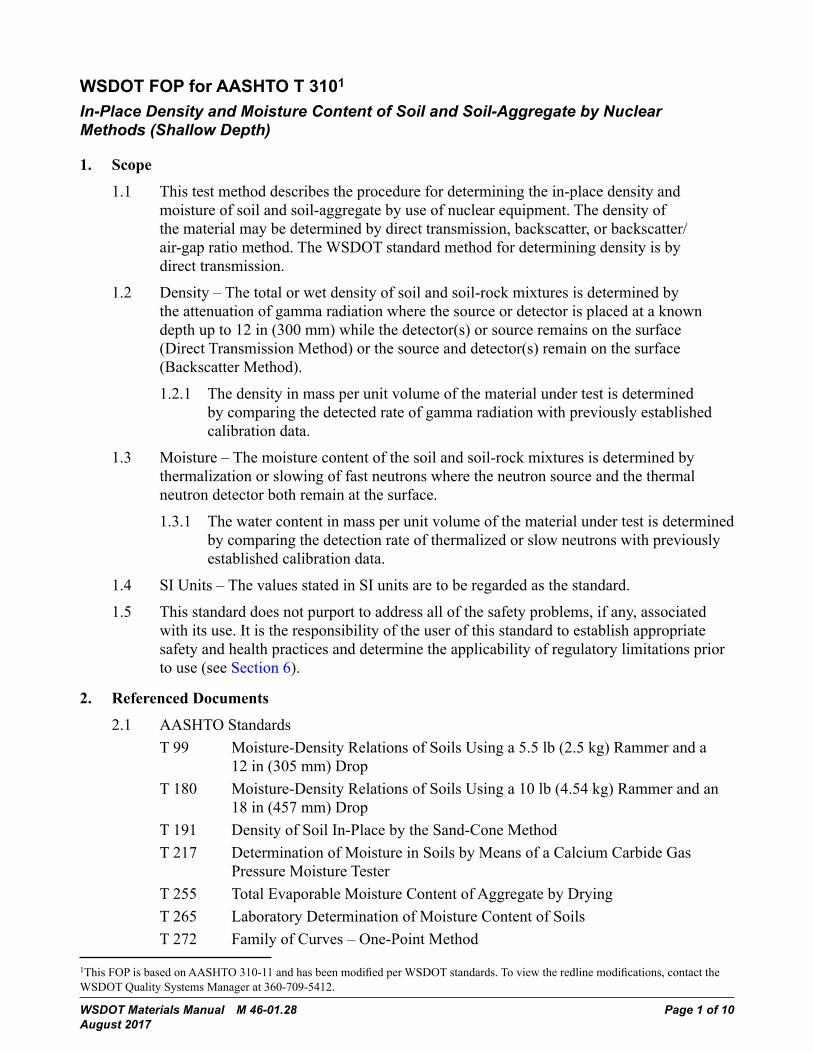
WSDOT FOP for AASHTO T 3101
In-Place Density and Moisture Content of Soil and Soil-Aggregate by Nuclear Methods (Shallow Depth)
1. Scope
1.1 This test method describes the procedure for determining the in-place density and moisture of soil and soil-aggregate by use of nuclear equipment. The density of the material may be determined by direct transmission, backscatter, or backscatter/air-gap ratio method. The WSDOT standard method for determining density is by direct transmission.
1.2 Density–Thetotalorwetdensityofsoilandsoil-rockmixturesisdeterminedbythe attenuation of gamma radiation where the source or detector is placed at a known depth up to 12 in (300 mm) while the detector(s) or source remains on the surface (Direct Transmission Method) or the source and detector(s) remain on the surface (Backscatter Method).
1.2.1 The density in mass per unit volume of the material under test is determined by comparing the detected rate of gamma radiation with previously established calibration data.
1.3 Moisture –The moisture content of the soil and soil-rock mixtures is determined by thermalization or slowing of fast neutrons where the neutron source and the thermal neutron detector both remain at the surface.
1.3.1 The water content in mass per unit volume of the material under test is determined by comparing the detection rate of thermalized or slow neutrons with previously established calibration data.
1.4 SIUnits–ThevaluesstatedinSIunitsaretoberegardedasthestandard.
1.5 This standard does not purport to address all of the safety problems, if any, associated with its use. It is the responsibility of the user of this standard to establish appropriate safety and health practices and determine the applicability of regulatory limitations prior to use (see Section 6).
2. Referenced Documents
2.1 AASHTOStandardsT 99 Moisture-Density Relations of Soils Using a 5.5 lb (2.5 kg) Rammer and a
12 in (305 mm) DropT 180 Moisture-Density Relations of Soils Using a 10 lb (4.54 kg) Rammer and an
18 in (457 mm) DropT 191 Density of Soil In-Place by the Sand-Cone MethodT 217 Determination of Moisture in Soils by Means of a Calcium Carbide Gas
Pressure Moisture TesterT 255 Total Evaporable Moisture Content of Aggregate by DryingT 265 Laboratory Determination of Moisture Content of SoilsT272 FamilyofCurves–One-PointMethod
1ThisFOPisbasedonAASHTO310-11andhasbeenmodifiedperWSDOTstandards.Toviewtheredlinemodifications,contacttheWSDOT Quality Systems Manager at 360-709-5412.
T 310 In-Place Density and Moisture Content of Soil and Soil-Aggregate by Nuclear Methods (Shallow Depth)
Page 2 of 10 WSDOT Materials Manual M 46-01.28 August 2017
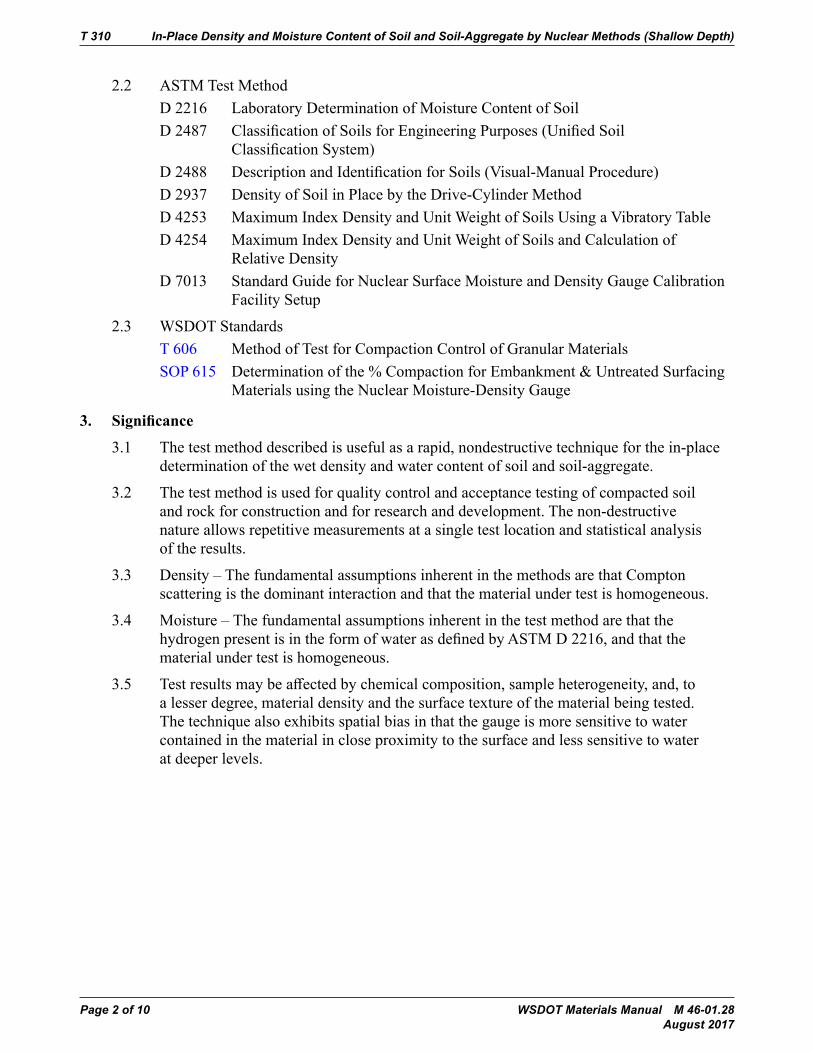
2.2 ASTM Test MethodD 2216 Laboratory Determination of Moisture Content of SoilD2487 ClassificationofSoilsforEngineeringPurposes(UnifiedSoil
ClassificationSystem)D2488 DescriptionandIdentificationforSoils(Visual-ManualProcedure)D 2937 Density of Soil in Place by the Drive-Cylinder MethodD 4253 Maximum Index Density and Unit Weight of Soils Using a Vibratory TableD 4254 Maximum Index Density and Unit Weight of Soils and Calculation of
Relative DensityD 7013 Standard Guide for Nuclear Surface Moisture and Density Gauge Calibration
Facility Setup
2.3 WSDOT StandardsT 606 Method of Test for Compaction Control of Granular MaterialsSOP 615 Determination of the % Compaction for Embankment & Untreated Surfacing
Materials using the Nuclear Moisture-Density Gauge
3. Significance
3.1 The test method described is useful as a rapid, nondestructive technique for the in-place determination of the wet density and water content of soil and soil-aggregate.
3.2 The test method is used for quality control and acceptance testing of compacted soil and rock for construction and for research and development. The non-destructive nature allows repetitive measurements at a single test location and statistical analysis of the results.
3.3 Density–ThefundamentalassumptionsinherentinthemethodsarethatCompton scattering is the dominant interaction and that the material under test is homogeneous.
3.4 Moisture–ThefundamentalassumptionsinherentinthetestmethodarethatthehydrogenpresentisintheformofwaterasdefinedbyASTMD2216,andthatthematerial under test is homogeneous.
3.5 Testresultsmaybeaffectedbychemicalcomposition,sampleheterogeneity,and,toa lesser degree, material density and the surface texture of the material being tested. The technique also exhibits spatial bias in that the gauge is more sensitive to water contained in the material in close proximity to the surface and less sensitive to water at deeper levels.
In-Place Density and Moisture Content of Soil and Soil-Aggregate by Nuclear Methods (Shallow Depth) T 310
WSDOT Materials Manual M 46-01.28 Page 3 of 10 August 2017
4. Interferences
4.1 In-Place Density Interferences
4.1.1 Thechemicalcompositionofthesamplemayaffectthemeasurement,andadjustments may be necessary.
4.1.2 The gauge is more sensitive to the density of the material in close proximity to the surface in the Backscatter Method.
Note 1: The nuclear gauge density measurements are somewhat biased to the surface layers of the soil being tested. This bias has largely been corrected out oftheDirectTransmissionMethodandanyremainingbiasisinsignificant.TheBackscatterMethodisstillmoresensitivetothematerialwithinthefirstseveralinches from the surface. Density measurements with direct transmission is the WSDOT standard method for soil and soil aggregate.
4.1.3 Oversize rocks or large voids in the source-detector path may cause higher or lower density determination. Since there is lack of uniformity in the soil due to layering, rock, or voids the test site beneath the gauge will be excavated and a representative sample will be taken to determine the gradation per WSDOT SOP 615.
4.1.4 Keep all other radioactive sources at least the minimum distance recommended bythemanufactureawayfromthegaugetoavoidaffectingthemeasurement.
4.2 In-Place Moisture Content Interferences
4.2.1 Thechemicalcompositionofthesamplemaydramaticallyaffectthemeasurementandadjustmentsmaybenecessary.Hydrogeninformsotherthanwater,asdefinedbyASTMD2216,andcarbonwillcausemeasurementsinexcessofthe true value. Some chemical elements such as boron, chlorine, and minute quantities of cadmium will cause measurements lower than the true value.
4.2.2 The water content determined by this test method is not necessarily the average water within the volume of the sample involved in the measurement. The measurementisheavilyinfluencedbythewatercontentofthematerialclosestto the surface. The volume of soil and rock represented in the measurement is indeterminate and will vary with the water content of the material. In general, the greater the water content of the material, the smaller the volume involved in the measurement. At 10 lbs/ft3 (160 kg/m3), approximately 50 percent of the typical measurement results from the water content of the upper 2 to 3 in (50 to 75 mm).
4.2.3 Keep all other neutron sources at least the minimum distance recommended bythemanufactureawayfromthegaugetoavoidaffectingthemeasurement.
T 310 In-Place Density and Moisture Content of Soil and Soil-Aggregate by Nuclear Methods (Shallow Depth)
Page 4 of 10 WSDOT Materials Manual M 46-01.28 August 2017
5. Apparatus
5.1 Nuclear Density/Moisture Gauge – While exact details of construction of the gauge may vary, the system shall consist of:
5.1.1 A sealed source of high energy gamma radiation such as cesium or radium.
5.1.2 Gamma Detector – Any type of gamma detector such as a Geiger-Mueller tube(s).
5.2 Fast Neutron Source – A sealed mixture of a radioactive material such as americium, radium, or californium-252 and a target material such as beryllium.
5.3 Slow Neutron Detector – Anytypeofslowneutrondetectorsuchasborontrifluorideor helium-3 proportional counter.
5.4 Reference Standard – A block of material used for checking instrument operation, correction of source decay, and to establish conditions for a reproducible reference count rate.
5.5 Site Preparation Device – A plate, straightedge, or other suitable leveling tool which may be used for planing the test site to the required smoothness, and in the Direct Transmission Method, guiding the drive pin to prepare a perpendicular hole.
5.6 Drive Pin – A pin not to exceed the diameter of the rod in the Direct Transmission Gauge by more than ¼ in (6 mm) or as recommended by the gauge manufacturer used to prepare a hole in the material under test for inserting the rod.
5.7 Hammer – Hand-heldhammerofsufficientsizeandweighttodrivethedrivepinintothematerial being tested. A slide hammer with an attached drive pin is an acceptable alternate totheDrivePin,Hammer,andDrivePinExtractor.
5.8 DrivePinExtractor–Atoolthatmaybeusedtoremovethedrivepininaverticaldirection so that the pin will not distort the hole in the extraction process.
6. Hazards
6.1 This gauge utilizes radioactive materials that may be hazardous to the health of the users unless proper precautions are taken. Users of this gauge must become familiar with applicable safety procedures and government regulations.
6.2 Effectiveuserinstructionstogetherwithroutinesafetyprocedures,suchassourceleaktests,recording,andevaluationoffilmbadgedata,etc.,arearecommendedpartoftheoperation and storage of this gauge.
7. Calibration
Nuclear gauges used for the purpose of acceptance testing, independent assurance testing, or dispute resolution shall be calibrated
WSDOT-owned nuclear density gauges will be calibrated by WSDOT using the manufacturer’s recommended procedures or may be calibrated by an external calibration facility that has been approved by the State Materials Engineer.
NucleargaugesthatarenotownedbyWSDOTshallbecalibratedinaccordancewithAASHTOT 310 Annexes A1, A 2, and A3.
In-Place Density and Moisture Content of Soil and Soil-Aggregate by Nuclear Methods (Shallow Depth) T 310
WSDOT Materials Manual M 46-01.28 Page 5 of 10 August 2017
8. Standardization
8.1 Turn the gauge on and allow it to stabilize for a minimum of 45 minutes prior to standardization. Leave the power on during the day’s testing.
Note 2:Ifforanyreasonthegaugelosespoweroristurnedoffduringtheworkperiod,the Standard Count must be re-established prior to use.
8.2 Standardize the gauge at the start of each day’s work and as often as deemed necessary by the operator or agency. Daily variations in Standard Count shall not exceed the daily variations established by the manufacturer of the gauge. Compare the daily Standard Count to the Density Standard Decay Sheet (Note 3) to ensure the Standard Count falls within acceptable limits. If the daily variations are exceeded after repeating the standardization procedure or if the daily Standard Count is outside the range of the Standard Decay Sheet, the gauge should be repaired and or recalibrated.
8.3 Record the Standard Count for both density and moisture in the Daily Standard Count Log. The exact procedure for standard count is listed in the manufacturer’s operators manual.
Note 3: The Density Standard Decay Sheet is located in the calibration documentation. This sheet shows the anticipated Standard Count range based on the calculated decay rate of the gauges radioactive source over the passage of time.
9. Procedure
9.1 Select a test location per WSDOT SOP 615.
9.2 Prepare the test site in the following manner:
9.2.1 Remove all loose and disturbed material and additional material as necessary to expose the top of the material to be tested.
Note 4: The spatial bias should be considered in determining the depth at which the gauge is to be seated.
9.2.2 Selectahorizontalareasufficientinsizetoaccommodatefourgaugereadingsthat will be 90° to each other. Plane the area to a smooth condition so as to obtain maximum contact between the gauge and the material being tested.
9.2.3 Themaximumvoidbeneaththegaugeshallnotexceed⅛in(3mm).Usenativefinesorfinesandtofillthevoidsandsmooththesurfacewitharigidplateorothersuitabletool.Thedepthofthefillershallnotexceedapproximately⅛in(3 mm).
9.3 This section has been deleted because WSDOT does not use this method.
9.4 Direct Transmission Method of In-Place Nuclear Density and Moisture Content
9.4.1 When selecting a test location, the tester shall visually select a site where the leastcompactiveefforthasbeenapplied.Selectatestlocationwherethegaugewill be at least 6 in (150 mm) away from any vertical mass. If closer than 24 in (600 mm) to a vertical mass, such as in a trench, follow gauge manufacturer correction procedures.
The test location should be at least 33 ft (10 m) away from other sources of radioactivity and at least 10 ft (3 m) away from large objects or the minimum distance recommended by the manufacturer, whichever is the greater distance.
T 310 In-Place Density and Moisture Content of Soil and Soil-Aggregate by Nuclear Methods (Shallow Depth)
Page 6 of 10 WSDOT Materials Manual M 46-01.28 August 2017
9.4.2 Make a hole perpendicular to the prepared surface using the guide and the hole-forming device (Section 5). The hole shall be a minimum of 2 in (50 mm) deeper than the desired measurement depth and of an alignment that insertion of the probe will not cause the gauge to tilt from the plane of the prepared area.
9.4.3 Mark the test area to allow the placement of the gauge over the test site and to allow the alignment of the source rod to the hole. Follow manufacturer recommendations if applicable.
Note 5: For alignment purposes, the user may expose the source rod for a maximum of ten seconds.
9.4.4 Remove the hole forming device carefully to prevent the distortion of the hole, damage to the surface, or loose material to fall into the hole.
Note 6: If the hole cannot be maintained, contact the Regional Materials Laboratory for directions on how to proceed.
9.4.5 Place the instrument on the material to be tested, making sure of maximum surface contact as described above.
9.4.6 Lower the source rod into the hole to the desired test depth. Pull gently on the gauge in the direction that will bring the side of the probe to face the center of the gauge so that the probe is in intimate contact with the side of the hole in the gamma measurement path.
9.4.7 If the gauge is so equipped, set the depth selector to the same depth as the probe before recording the automated (gauge computed densities, moisture contents, and weights) values.
9.4.8 Secure and record one, one minute dry density and moisture content readings, then turn the gauge 90º and perform another set of readings. If the two dry density readings are not within 3 lbs/cf (50 kg/m3) of each other, see Note 7.
Note 7: If two readings are not within tolerances stated, rotate gauge 90º and retest. Again compare both 90º readings. If after four readings the results are not within the tolerances stated, rotate gauge 90º and retest. Again compare both readings. If these reading are still not within tolerances stated, move to another location to perform test.
In-Place Density and Moisture Content of Soil and Soil-Aggregate by Nuclear Methods (Shallow Depth) T 310
WSDOT Materials Manual M 46-01.28 Page 7 of 10 August 2017
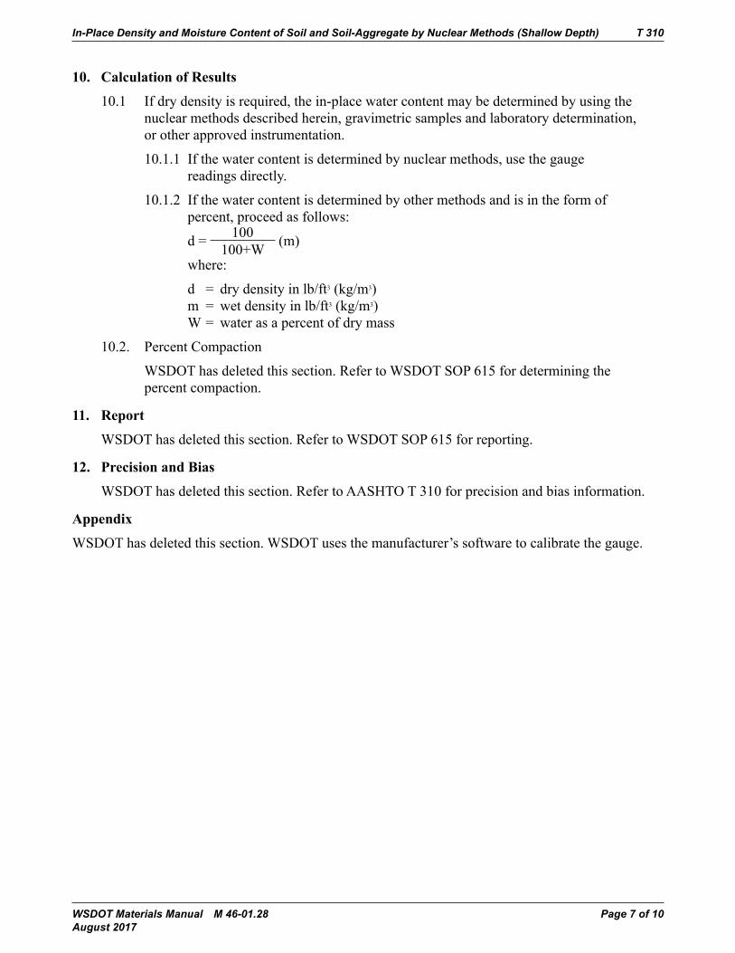
10. CalculationofResults
10.1 If dry density is required, the in-place water content may be determined by using the nuclear methods described herein, gravimetric samples and laboratory determination, or other approved instrumentation.
10.1.1 If the water content is determined by nuclear methods, use the gauge readings directly.
10.1.2 If the water content is determined by other methods and is in the form of percent, proceed as follows:
d = 100 100+W (m)
where:
d = dry density in lb/ft3 (kg/m3) m = wet density in lb/ft3 (kg/m3) W = water as a percent of dry mass
10.2. Percent Compaction
WSDOT has deleted this section. Refer to WSDOT SOP 615 for determining the percent compaction.
11. Report
WSDOT has deleted this section. Refer to WSDOT SOP 615 for reporting.
12. PrecisionandBias
WSDOThasdeletedthissection.RefertoAASHTOT310forprecisionandbiasinformation.
Appendix
WSDOT has deleted this section. WSDOT uses the manufacturer’s software to calibrate the gauge.

T 310 In-Place Density and Moisture Content of Soil and Soil-Aggregate by Nuclear Methods (Shallow Depth)
Page 8 of 10 WSDOT Materials Manual M 46-01.28 August 2017
WSDOT Materials Manual M 46-01.28 Page 9 of 10 August 2017
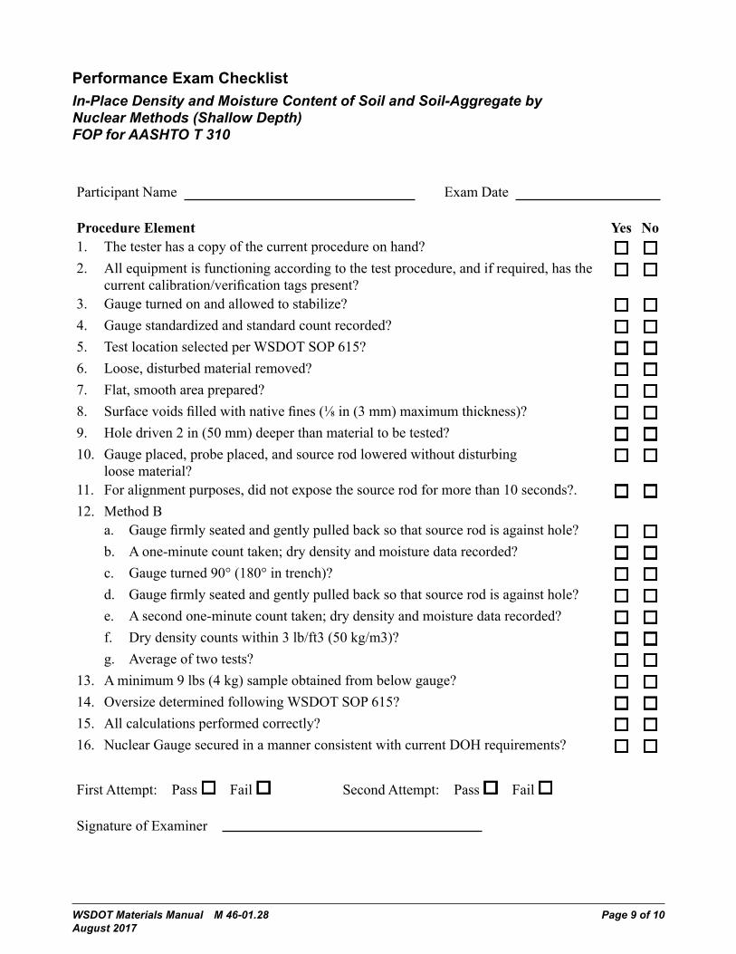
Performance Exam ChecklistIn-Place Density and Moisture Content of Soil and Soil-Aggregate by Nuclear Methods (Shallow Depth) FOP for AASHTO T 310
Participant Name Exam Date
ProcedureElement Yes No1. The tester has a copy of the current procedure on hand?2. All equipment is functioning according to the test procedure, and if required, has the
currentcalibration/verificationtagspresent?3. Gauge turned on and allowed to stabilize?4. Gauge standardized and standard count recorded?5. Test location selected per WSDOT SOP 615?6. Loose, disturbed material removed?7. Flat, smooth area prepared?8. Surfacevoidsfilledwithnativefines(⅛in(3mm)maximumthickness)?9. Holedriven2in(50mm)deeperthanmaterialtobetested?10. Gauge placed, probe placed, and source rod lowered without disturbing
loose material?11. For alignment purposes, did not expose the source rod for more than 10 seconds?.12. Method B
a. Gaugefirmlyseatedandgentlypulledbacksothatsourcerodisagainsthole?b. A one-minute count taken; dry density and moisture data recorded?c. Gauge turned 90° (180° in trench)?d. Gaugefirmlyseatedandgentlypulledbacksothatsourcerodisagainsthole?e. A second one-minute count taken; dry density and moisture data recorded?f. Dry density counts within 3 lb/ft3 (50 kg/m3)?g. Average of two tests?
13. A minimum 9 lbs (4 kg) sample obtained from below gauge?14. Oversize determined following WSDOT SOP 615?15. All calculations performed correctly?16. NuclearGaugesecuredinamannerconsistentwithcurrentDOHrequirements?
First Attempt: Pass Fail Second Attempt: Pass Fail
Signature of Examiner

T 310 In-Place Density and Moisture Content of Soil and Soil-Aggregate by Nuclear Methods (Shallow Depth)
Page 10 of 10 WSDOT Materials Manual M 46-01.28 August 2017
Comments:
WSDOT Materials Manual M 46-01.28 Page 1 of 10 August 2017
WSDOT FOP for AASHTO T 355In-Place Density of Asphalt Mixtures Using the Nuclear Moisture-Density GaugeScope
This test method describes a procedure for determining the density of asphalt mixtures by means of a nuclear gauge using the backscatter or thin layer method in accordance withAASHTOT355-15.CorrelationwithdensitiesdeterminedundertheFOPforAASHTOT166isrequiredbysomeagencies.
Apparatus• Nuclear density gauge with the factory-matched standard reference block.• Transport case for properly shipping and housing the gauge and tools.• Instructionmanualforthespecificmakeandmodelofgauge.• Radioactive materials information and calibration packet containing:
– Daily standard count log– Factory and laboratory calibration data sheet– Leaktestcertificate– Shippers’ declaration for dangerous goods– Procedure memo for storing, transporting and handling nuclear
testing equipment– Other radioactive materials documentation as required by local
regulatory requirements
Material• WSDOTdoesnotusefillermaterial
Radiation SafetyThis method does not purport to address all of the safety problems associated with its use. This test method involves potentially hazardous materials. The gauge utilizes radioactive materials that may be hazardous to the health of the user unless proper precautions are taken. Users of this gauge must become familiar with the applicable safety procedures and governmental regulations. All operators will be trained in radiation safety prior to operating nuclear density gauges. Some agencies require the useofpersonalmonitoringdevicessuchasathermoluminescentdosimeterorfilmbadge.Effectiveinstructions,togetherwithroutinesafetyproceduressuchassourceleak tests, recording and evaluation of personal monitoring device data, etc., are a recommended part of the operation and storage of this gauge.

T 355 In-Place Density of Asphalt Mixtures Using the Nuclear Moisture-Density Gauge
Page 2 of 10 WSDOT Materials Manual M 46-01.28 August 2017
Calibration Calibrate the nuclear gauge as required by the agency. This calibration may be performed by the agency using the manufacturer’s recommended procedures or by other facilities approved by the agency. Verify or re-establish calibration curves, tables, orequivalentcoefficientsevery12months.
Standardization (Standard Count)1. Turn the gauge on and allow it to stabilize for a minimum of 45 minutes prior to
taking a Standard Count. Leave the power on during the day’s testing.
Note 1: Ifforanyreasonthegaugelosespoweroristurnedoffduringtheworkperiod, the Standard Count must be re-established prior to use.
2. Prior to any correlation of the nuclear gauge, perform a Stat Test in accordance with the gauge’s operator manual. If the gauge passes the Stat Test, perform a Standard Count. If the gauge fails the Stat Test, run a second Stat Test. If the gauge fails the second Stat Test, it should be repaired or recalibrated.
3. Take a Standard Count at the start of each day’s work and as often as deemed necessary by the operator or agency. Daily variations in Standard Count shall not exceed the daily variations established by the manufacturer of the gauge. Compare the daily Standard Count to the Density Standard Decay Sheet (Note 2) to ensure the standard count falls within acceptable limits. If the daily variations in Standard Count are exceeded after repeating the Standard Count procedure or if the daily Standard Count is outside the range of the Standard Decay Sheet, the gauge should be repaired and or recalibrated.
4. Record the Standard Count for both density and moisture in the Daily Standard Count Log. Instructions for taking a Standard Count are found in the gauge’s operator manual.
Note 2: The Density Standard Decay Sheet is found in the calibration documentation packet. This sheet shows the anticipated standard count range based on the calculated decay rate of the gauges radioactive source over the passage of time.
In-Place Density of Asphalt Mixtures Using the Nuclear Moisture-Density Gauge T 355
WSDOT Materials Manual M 46-01.28 Page 3 of 10 August 2017
Test Site LocationSelect a test location(s) randomly and in accordance with WSDOT Test Method T 716. Testsitesshouldberelativelysmoothandflatandmeetthefollowingconditions:
a. At least 30 ft. (10 m) away from other sources of radioactivity.
b. At least 10 ft. (3 m) away from large objects.
c. If the gauge will be closer than 24 in (600 mm) to any vertical mass, or less than 6 in (150 mm) from a vertical pavement edge, use the gauge manufacturer’s correction procedure.
ProcedurePlace the gauge on the test site. Using a crayon (not spray paint), mark the outline or footprint of the gauge. Extend the probe to the backscatter position.
Method1–Averageoftwoone-minutetestsWSDOTdoesnotuseMethod1
1. Take a one-minute test and record the wet density reading.
2. Rotate the gauge 90 degrees centered over the original footprint. Mark the outline or footprint of the gauge.
3. Take another one-minute test and record the wet density reading.
4. Ifthedifferencebetweenthetwoone-minutetestsisgreaterthan2.5lb/ft3 (40 kg/m3),retestinbothdirections.Ifthedifferenceoftheretestsisstillgreaterthan 2.5 lb/ft3 (40 kg/m3) test at 180 and 270 degrees.
5. The density reported for each test site shall be the average of the two individual one-minute wet density readings.
IN-PLACE DENSITY WSDOT FOPAASHTOT355(15)
WSDOT FOP_52_T355_short_15 WSDOT proposal.docx E&B&IP 20-4Pub. October 2016
Procedure
1. Place the gauge on the test site. Using a crayon (not spray paint), mark the outline or footprint of the gauge. Extend the probe to the backscatter position.
Method 1 – Averageoftwoone-minute tests WSDOT does not use Method 1
1. Take a one-minute test and record the wet density reading.
2. Rotate the gauge 90 degrees centered over the original footprint. Mark the outline or footprint of the gauge.
3. Take another one-minute test and record the wet density reading.
4. If the difference between the two one-minute tests is greater than 40 kg/m3 (2.5 lb/ft3), retest in both directions. If the difference of the retests is still greater than 40 kg/m3
(2.5 lb/ft3) test at 180 and 270 degrees.
5. The density reported for each test site shall be the average of the two individual one-minute wet density readings.
Method 1 - Footprintofthegaugetestsite
Method 2 – One four minute test
1. Ensure the depth entered into the gauge matches the pavement depth and the depth at which the gauge was correlated.
Footprint of The Gauge Test SiteMethod 1
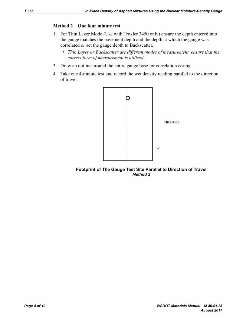
T 355 In-Place Density of Asphalt Mixtures Using the Nuclear Moisture-Density Gauge
Page 4 of 10 WSDOT Materials Manual M 46-01.28 August 2017
Method 2 – One four minute test
1. For Thin Layer Mode (Use with Troxler 3450 only) ensure the depth entered into the gauge matches the pavement depth and the depth at which the gauge was correlated or set the gauge depth to Backscatter.• Thin Layer or Backscatter are different modes of measurement, ensure that the
correct form of measurement is utilized.
3. Draw an outline around the entire gauge base for correlation coring.
4. Take one 4-minute test and record the wet density reading parallel to the direction of travel.
IN-PLACE DENSITY WSDOT FOP AASHTO T 355 (15)
WSDOT FOP_52_T355_short_15 WSDOT proposal (2).docx E&B&IP 20-2Pub. October 2016
ProcedureMethod 2 – One four minute test
1. Ensure the depth entered into the gauge matches the pavement depth and the depth at which the gauge was correlated.
2. Draw an outline around the entire gauge base for correlation coring.
3. Take one 4-minute test and record the wet density reading parallel to the direction of travel.
Method 2 - Footprint of the gauge test site parallel to direction of travel
Calculation of Results
Percent compaction is determined by comparing the in-place wet density as determined by this method to the appropriate agency density standard. See appropriate agency policy for use of density standards.
Example for Method 1:
Reading #1: 141.5 lb/ft3
Reading #2: 140.1 lb/ft3 Are the two readings within the tolerance? (YES)
Reading average: 140.8 lb/ft3
Core correction : +2.1 lb/ft3
Direction
Comment [JDM1]: Do we need an example for Method 2?
Footprint of The Gauge Test Site Parallel to Direction of TravelMethod 2
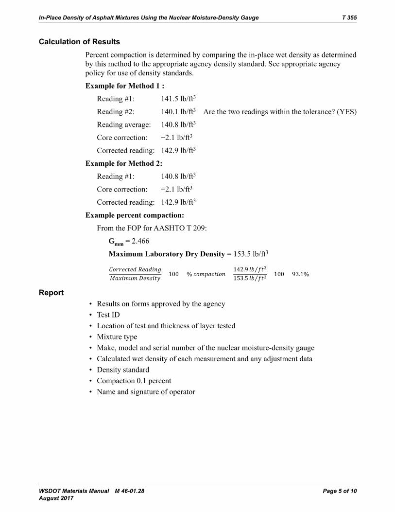
In-Place Density of Asphalt Mixtures Using the Nuclear Moisture-Density Gauge T 355
WSDOT Materials Manual M 46-01.28 Page 5 of 10 August 2017
Calculation of ResultsPercent compaction is determined by comparing the in-place wet density as determined by this method to the appropriate agency density standard. See appropriate agency policy for use of density standards.
ExampleforMethod1:
Reading #1: 141.5 lb/ft3
Reading #2: 140.1 lb/ft3 Are the two readings within the tolerance? (YES)
Reading average: 140.8 lb/ft3
Core correction: +2.1 lb/ft3
Corrected reading: 142.9 lb/ft3
ExampleforMethod2:
Reading #1: 140.8 lb/ft3
Core correction: +2.1 lb/ft3
Corrected reading: 142.9 lb/ft3
Examplepercentcompaction:
FromtheFOPforAASHTOT209:
Gmm = 2.466
MaximumLaboratoryDryDensity = 153.5 lb/ft3
IN-PLACE DENSITY WSDOT FOP AASHTOT355(15)
WSDOT FOP_52_T355_short_15 WSDOT proposal (2).docx E&B&IP 20-1Pub. October 2016
Calculation of Results
Percent compaction is determined by comparing the in-place wet density as determined by this method to the appropriate agency density standard. See appropriate agency policy for use of density standards.
Example for Method 1:
Reading #1: 141.5 lb/ft3
Reading #2: 140.1 lb/ft3 Are the two readings within the tolerance? (YES)
Reading average: 140.8 lb/ft3
Core correction : +2.1 lb/ft3
Corrected reading: 142.9 lb/ft3
Example for Method 2:
Reading #1: 140.8 lb/ft3
Core correction : +2.1 lb/ft3
Corrected reading: 142.9 lb/ft3Examplepercentcompaction:
FromtheFOPforAASHTOT209:
Gmm = 2.466
MaximumLaboratoryDryDensity = 153.5 lb/ft3
𝐶𝐶𝐶𝐶𝐶𝐶𝐶𝐶𝐶𝐶𝐶𝐶𝐶𝐶𝐶𝐶𝐶𝐶𝐶𝐶𝐶𝐶𝐶𝐶𝐶𝐶𝐶𝐶𝐶𝐶𝐶𝐶𝐶𝐶𝐶𝐶 𝑅𝑅𝑅𝑅𝐶𝐶𝐶𝐶𝑅𝑅𝑅𝑅𝐶𝐶𝐶𝐶𝑅𝑅𝑅𝑅𝑅𝑅𝑅𝑅𝑅𝑅𝑅𝑅𝑀𝑀𝑀𝑀𝑅𝑅𝑅𝑅𝑀𝑀𝑀𝑀𝑅𝑅𝑅𝑅𝑀𝑀𝑀𝑀𝑀𝑀𝑀𝑀𝑀𝑀𝑀𝑀 𝐷𝐷𝐷𝐷𝐶𝐶𝐶𝐶𝑅𝑅𝑅𝑅𝐷𝐷𝐷𝐷𝑅𝑅𝑅𝑅𝐶𝐶𝐶𝐶𝐷𝐷𝐷𝐷
× 100 = % 𝐶𝐶𝐶𝐶𝐶𝐶𝐶𝐶𝑀𝑀𝑀𝑀𝑐𝑐𝑐𝑐𝑅𝑅𝑅𝑅𝐶𝐶𝐶𝐶𝐶𝐶𝐶𝐶𝑅𝑅𝑅𝑅𝐶𝐶𝐶𝐶𝑅𝑅𝑅𝑅 142.9 𝑙𝑙𝑙𝑙𝑙𝑙𝑙𝑙 𝑓𝑓𝑓𝑓𝐶𝐶𝐶𝐶3⁄153.5 𝑙𝑙𝑙𝑙𝑙𝑙𝑙𝑙 𝑓𝑓𝑓𝑓𝐶𝐶𝐶𝐶3⁄ × 100 = 93.1%
Report
• Results on forms approved by the agency
• Test ID
• Location of test and thickness of layer tested
• Mixture type
Comment [JDM1]: Do we need an example for Method 2?
Report• Results on forms approved by the agency• Test ID• Location of test and thickness of layer tested• Mixture type• Make, model and serial number of the nuclear moisture-density gauge• Calculated wet density of each measurement and any adjustment data• Density standard• Compaction 0.1 percent • Name and signature of operator
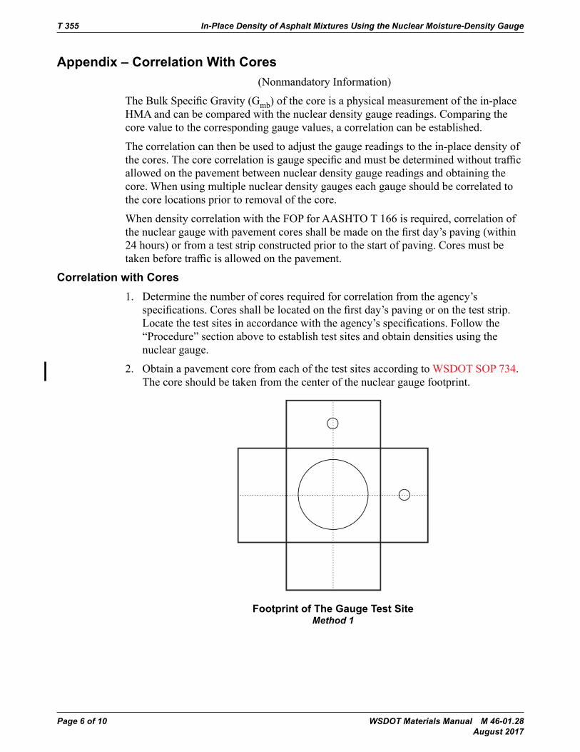
T 355 In-Place Density of Asphalt Mixtures Using the Nuclear Moisture-Density Gauge
Page 6 of 10 WSDOT Materials Manual M 46-01.28 August 2017
Appendix – Correlation With Cores(Nonmandatory Information)
TheBulkSpecificGravity(Gmb) of the core is a physical measurement of the in-place HMAandcanbecomparedwiththenucleardensitygaugereadings.Comparingthecore value to the corresponding gauge values, a correlation can be established.
The correlation can then be used to adjust the gauge readings to the in-place density of thecores.Thecorecorrelationisgaugespecificandmustbedeterminedwithouttrafficallowed on the pavement between nuclear density gauge readings and obtaining the core. When using multiple nuclear density gauges each gauge should be correlated to the core locations prior to removal of the core.
WhendensitycorrelationwiththeFOPforAASHTOT166isrequired,correlationofthenucleargaugewithpavementcoresshallbemadeonthefirstday’spaving(within24 hours) or from a test strip constructed prior to the start of paving. Cores must be takenbeforetrafficisallowedonthepavement.
Correlation with Cores1. Determine the number of cores required for correlation from the agency’s
specifications.Coresshallbelocatedonthefirstday’spavingorontheteststrip.Locatethetestsitesinaccordancewiththeagency’sspecifications.Followthe“Procedure” section above to establish test sites and obtain densities using the nuclear gauge.
2. Obtain a pavement core from each of the test sites according to WSDOT SOP 734. The core should be taken from the center of the nuclear gauge footprint.
IN-PLACE DENSITY WSDOT FOP AASHTO T 355 (15)
WSDOT FOP_52_T355_short_15 WSDOT proposal (2).docx E&B&IP 20-1Pub. October 2016
APPENDIX – CORRELATION WITH CORES
Method 1 - Footprint of the gauge test site.
Method 2 - Footprint of the gauge test site.
1. Determine the density of the cores by the FOP for AASHTO T 166, Bulk Specific Gravity of Compacted Asphalt Mixtures Using Saturated Surface Dry Specimens.
2. Calculate a correlation factor for the nuclear gauge reading as follows:
Direction of traffic
Footprint of The Gauge Test SiteMethod 1
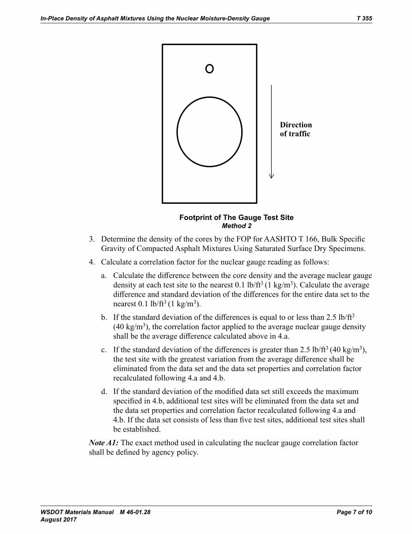
In-Place Density of Asphalt Mixtures Using the Nuclear Moisture-Density Gauge T 355
WSDOT Materials Manual M 46-01.28 Page 7 of 10 August 2017
IN-PLACE DENSITY WSDOT FOP AASHTO T 355 (15)
WSDOT FOP_52_T355_short_15 WSDOT proposal (2).docx E&B&IP 20-1Pub. October 2016
APPENDIX – CORRELATION WITH CORES
Method 1 - Footprint of the gauge test site.
Method 2 - Footprint of the gauge test site.
1. Determine the density of the cores by the FOP for AASHTO T 166, Bulk Specific Gravity of Compacted Asphalt Mixtures Using Saturated Surface Dry Specimens.
2. Calculate a correlation factor for the nuclear gauge reading as follows:
Direction oftraffic
Footprint of The Gauge Test SiteMethod 2
3. DeterminethedensityofthecoresbytheFOPforAASHTOT166,BulkSpecificGravity of Compacted Asphalt Mixtures Using Saturated Surface Dry Specimens.
4. Calculate a correlation factor for the nuclear gauge reading as follows:
a. Calculatethedifferencebetweenthecoredensityandtheaveragenucleargaugedensity at each test site to the nearest 0.1 lb/ft3 (1 kg/m3). Calculate the average differenceandstandarddeviationofthedifferencesfortheentiredatasettothenearest 0.1 lb/ft3 (1 kg/m3).
b. Ifthestandarddeviationofthedifferencesisequaltoorlessthan2.5lb/ft3 (40 kg/m3), the correlation factor applied to the average nuclear gauge density shallbetheaveragedifferencecalculatedabovein4.a.
c. Ifthestandarddeviationofthedifferencesisgreaterthan2.5lb/ft3 (40 kg/m3), thetestsitewiththegreatestvariationfromtheaveragedifferenceshallbeeliminated from the data set and the data set properties and correlation factor recalculated following 4.a and 4.b.
d. Ifthestandarddeviationofthemodifieddatasetstillexceedsthemaximumspecifiedin4.b,additionaltestsiteswillbeeliminatedfromthedatasetandthe data set properties and correlation factor recalculated following 4.a and 4.b.Ifthedatasetconsistsoflessthanfivetestsites,additionaltestsitesshallbe established.
Note A1: The exact method used in calculating the nuclear gauge correlation factor shallbedefinedbyagencypolicy.
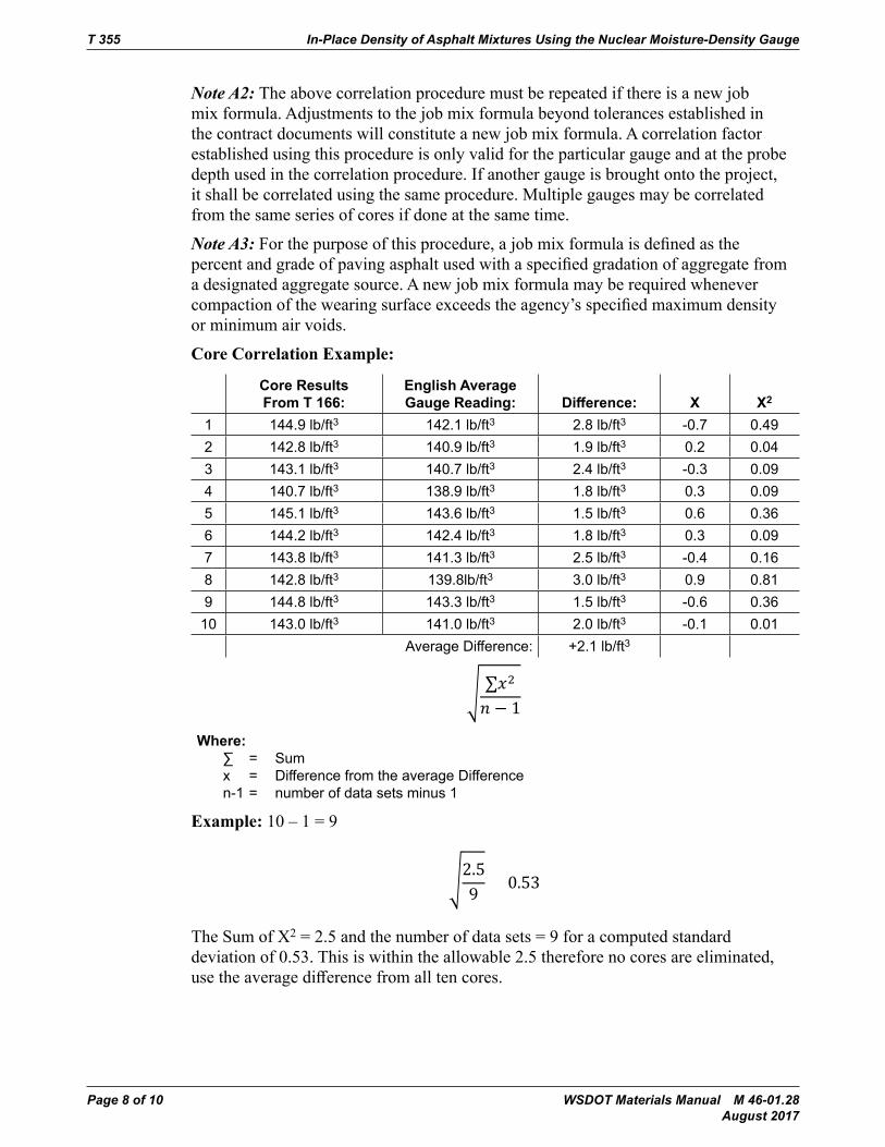
T 355 In-Place Density of Asphalt Mixtures Using the Nuclear Moisture-Density Gauge
Page 8 of 10 WSDOT Materials Manual M 46-01.28 August 2017
Note A2: The above correlation procedure must be repeated if there is a new job mix formula. Adjustments to the job mix formula beyond tolerances established in the contract documents will constitute a new job mix formula. A correlation factor established using this procedure is only valid for the particular gauge and at the probe depth used in the correlation procedure. If another gauge is brought onto the project, it shall be correlated using the same procedure. Multiple gauges may be correlated from the same series of cores if done at the same time.
Note A3: Forthepurposeofthisprocedure,ajobmixformulaisdefinedasthepercentandgradeofpavingasphaltusedwithaspecifiedgradationofaggregatefroma designated aggregate source. A new job mix formula may be required whenever compactionofthewearingsurfaceexceedstheagency’sspecifiedmaximumdensityor minimum air voids.
CoreCorrelationExample:
Core Results From T 166:
English Average Gauge Reading: Difference: X X2
1 144.9 lb/ft3 142.1 lb/ft3 2.8 lb/ft3 -0.7 0.492 142.8 lb/ft3 140.9 lb/ft3 1.9 lb/ft3 0.2 0.043 143.1 lb/ft3 140.7 lb/ft3 2.4 lb/ft3 -0.3 0.094 140.7 lb/ft3 138.9 lb/ft3 1.8 lb/ft3 0.3 0.095 145.1 lb/ft3 143.6 lb/ft3 1.5 lb/ft3 0.6 0.366 144.2 lb/ft3 142.4 lb/ft3 1.8 lb/ft3 0.3 0.097 143.8 lb/ft3 141.3 lb/ft3 2.5 lb/ft3 -0.4 0.168 142.8 lb/ft3 139.8lb/ft3 3.0 lb/ft3 0.9 0.819 144.8 lb/ft3 143.3 lb/ft3 1.5 lb/ft3 -0.6 0.36
10 143.0 lb/ft3 141.0 lb/ft3 2.0 lb/ft3 -0.1 0.01Average Difference: +2.1 lb/ft3
IN-PLACE DENSITY WSDOT FOPAASHTOT355(15)
WSDOT FOP_52_T355_short_15 WSDOT proposal (2).docx E&B&IP 20-3Pub. October 2016
CoreCorrelationExample:
EnglishCore results from T 166:
Average Gauge reading:
Difference: X X2
1 144.9 lb/ft3 142.1 lb/ft3 2.8 lb/ft3 -0.7 0.492 142.8 lb/ft3 140.9 lb/ft3 1.9 lb/ft3 0.2 0.043 143.1 lb/ft3 140.7 lb/ft3 2.4 lb/ft3 -0.3 0.094 140.7 lb/ft3 138.9 lb/ft3 1.8 lb/ft3 0.3 0.095 145.1 lb/ft3 143.6 lb/ft3 1.5 lb/ft3 0.6 0.366 144.2 lb/ft3 142.4 lb/ft3 1.8 lb/ft3 0.3 0.097 143.8 lb/ft3 141.3 lb/ft3 2.5 lb/ft3 -0.4 0.168 142.8 lb/ft3 139.8lb/ft3 3.0 lb/ft3 0.9 0.819 144.8 lb/ft3 143.3 lb/ft3 1.5 lb/ft3 -0.6 0.3610 143.0 lb/ft3 141.0 lb/ft3 2.0 lb/ft3 -0.1 0.01
Average Difference: +2.1 lb/ft3
� ∑𝑥𝑥𝑥𝑥2
𝑛𝑛𝑛𝑛 − 1Where:
∑ = Sum x = Difference from the average Differencen-1 = number of data sets minus 1
Example: 10 – 1 = 9
�2.59
= 0.53
The Sum of X2 = 2.5 and the number of data sets = 9 for a computed standard deviation of 0.53. This is within the allowable 2.5 therefore no cores are eliminated, use the average difference from all ten cores.
Where: ∑ = Sum x = Difference from the average Difference n-1 = number of data sets minus 1
Example:10–1=9
IN-PLACE DENSITY WSDOT FOPAASHTOT355(15)
WSDOT FOP_52_T355_short_15 WSDOT proposal (2).docx E&B&IP 20-3Pub. October 2016
CoreCorrelationExample:
EnglishCore results from T 166:
Average Gauge reading:
Difference: X X2
1 144.9 lb/ft3 142.1 lb/ft3 2.8 lb/ft3 -0.7 0.492 142.8 lb/ft3 140.9 lb/ft3 1.9 lb/ft3 0.2 0.043 143.1 lb/ft3 140.7 lb/ft3 2.4 lb/ft3 -0.3 0.094 140.7 lb/ft3 138.9 lb/ft3 1.8 lb/ft3 0.3 0.095 145.1 lb/ft3 143.6 lb/ft3 1.5 lb/ft3 0.6 0.366 144.2 lb/ft3 142.4 lb/ft3 1.8 lb/ft3 0.3 0.097 143.8 lb/ft3 141.3 lb/ft3 2.5 lb/ft3 -0.4 0.168 142.8 lb/ft3 139.8lb/ft3 3.0 lb/ft3 0.9 0.819 144.8 lb/ft3 143.3 lb/ft3 1.5 lb/ft3 -0.6 0.3610 143.0 lb/ft3 141.0 lb/ft3 2.0 lb/ft3 -0.1 0.01
Average Difference: +2.1 lb/ft3
� ∑𝑥𝑥𝑥𝑥2
𝑛𝑛𝑛𝑛 − 1Where:
∑ = Sum x = Difference from the average Differencen-1 = number of data sets minus 1
Example: 10 – 1 = 9
�2.59
= 0.53
The Sum of X2 = 2.5 and the number of data sets = 9 for a computed standard deviation of 0.53. This is within the allowable 2.5 therefore no cores are eliminated, use the average difference from all ten cores.
The Sum of X2 = 2.5 and the number of data sets = 9 for a computed standard deviation of 0.53. This is within the allowable 2.5 therefore no cores are eliminated, usetheaveragedifferencefromalltencores.
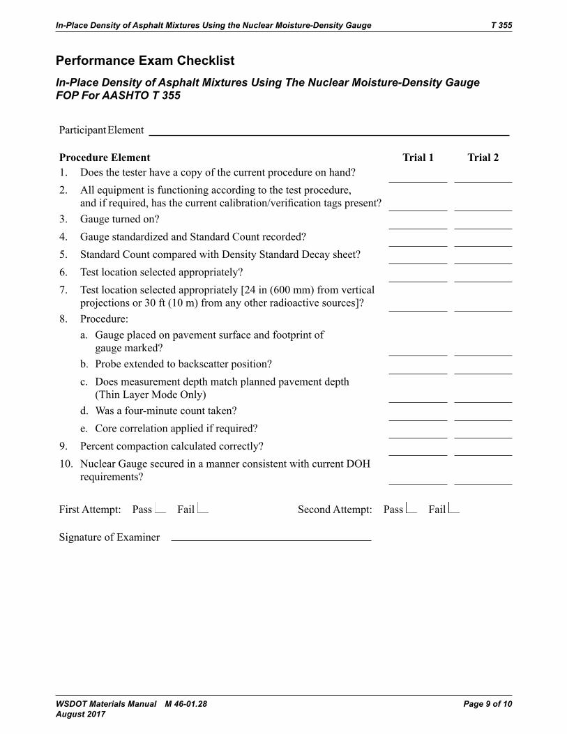
In-Place Density of Asphalt Mixtures Using the Nuclear Moisture-Density Gauge T 355
WSDOT Materials Manual M 46-01.28 Page 9 of 10 August 2017
Performance Exam ChecklistIn-Place Density of Asphalt Mixtures Using The Nuclear Moisture-Density Gauge FOP For AASHTO T 355
Participant Element
ProcedureElement Trial1 Trial21. Does the tester have a copy of the current procedure on hand?2. All equipment is functioning according to the test procedure,
andifrequired,hasthecurrentcalibration/verificationtagspresent?3. Gauge turned on? 4. Gauge standardized and Standard Count recorded?5. Standard Count compared with Density Standard Decay sheet? 6. Test location selected appropriately?7. Test location selected appropriately [24 in (600 mm) from vertical
projections or 30 ft (10 m) from any other radioactive sources]?8. Procedure:
a. Gauge placed on pavement surface and footprint of gauge marked?
b. Probe extended to backscatter position?c. Does measurement depth match planned pavement depth
(Thin Layer Mode Only)d. Was a four-minute count taken?e. Core correlation applied if required?
9. Percent compaction calculated correctly?10. NuclearGaugesecuredinamannerconsistentwithcurrentDOH
requirements?
First Attempt: Pass Fail Second Attempt: Pass Fail
Signature of Examiner

T 355 In-Place Density of Asphalt Mixtures Using the Nuclear Moisture-Density Gauge
Page 10 of 10 WSDOT Materials Manual M 46-01.28 August 2017
Comments:
WSDOT Materials Manual M 46-01.28 Page 1 of 6 August 2017
WSDOT Standard Operating Procedure SOP 615Determination of the % Compaction for Embankment & Untreated Surfacing Materials Using the Nuclear Moisture-Density Gauge
1. Scope
This procedure covers the procedures for determining the in-place density, moisture content, gradation analysis, oversize correction, and determination of maximum density of compacted soils and untreated surfacing materials using a nuclear density device in the direct transmission mode.
2. References
a. AASHTOT99forMethodofTestforMoisture-DensityRelationsofSoils
b. AASHTOT180forMethodofTestforMoisture-DensityRelationsofSoils
c. T 255–WSDOTFOPforAASHTOforTotalMoistureContentofAggregatebyDrying
d. T 272–WSDOTFOPforAASHTOforFamilyofCurves–OnePointMethod
e. T 310–WSDOTFOPforAASHTOforIn-PlaceDensitiesandMoistureContentofSoilsandSoil-Aggregate by Nuclear Methods (Shallow Depth)
f. WSDOT T 606 Method of Test for Compaction Control of Granular Materials
3. TestLocation
When selecting a test location, the tester shall visually select a site where the least compactive efforthasbeenapplied.Selectatestlocationwherethegaugewillbeatleast6in(150mm)awayfrom any vertical mass. If closer than 24 in (600 mm) to a vertical mass, such as in a trench, follow gauge manufacturer correction procedures.
When retesting is required due to a failing test; retest within a 10-foot radius of the original station andoffset.
4. NuclearDensityTest
Determine the dry density and moisture content of soils and untreated surfacing materials using thenuclearmoisture-densitygaugeinaccordancewithWSDOTFOPforAASHTOT310,andrecord in the Materials Testing System (MATS), WSDOT Form 350-074, Field Density Test, or other form approved in writing by the State Materials Engineer.

Determination of the % Compaction for Embankment & SOP 615 Untreated Surfacing Materials Using the Nuclear Moisture-Density Gauge
Page 2 of 6 WSDOT Materials Manual M 46-01.28 August 2017
5. OversizeDetermination
a. AASHTOT99andWSDOTT606
A sample weighing a minimum of 4.08 kg (9 lbs) will be taken from beneath the gauge. Care shall be taken to select material that is truly representative of where the moisture density gauge determined the dry density and moisture content.
There are two methods for determining the percentage of material retained on the No. 4 sieve:
1. Method1–materialthatallowsfortheeasyseparationoffineandcoarseaggregate.
a. Dry the sample until no visible free moisture is present (material may still appear damp but will not be shiny).
b. Determine and record the mass of the sample to the nearest 0.1 percent of the total mass or better.
c. ShakethesamplebyhandoveraverifiedNo.4(4.75mm)sievetakingcarenottooverloadthesieve.OverloadingforaNo.4(4.75mm)sieveisdefinedas;Aretainedmass of more than 800 g (1.8 lbs), on a 12 inch sieve, or 340 g, (0.75 lbs); on an 8 inch sieve after sieving is complete.
Note 1: If the tester suspects a sieve will be overloaded the sample can be separated into smaller increments and recombined after sieving.
d. Determine and record the mass of the material retained on the No. 4 (4.75 mm) sieve to the nearest 0.1 percent of the total mass or better and record.
2. Method2–recommendedforcrushedsurfacingmaterials,materialswithhighclaycontent, or other granular materials that are at or near the optimum moisture content for compaction.
a. Determine and record the mass of the sample to the nearest 0.1 percent of the total mass or better and record.
b. ShakesamplebyhandoveraverifiedNo.4(4.75mm)sieve.Donotoverloadthesieve.(SeeSection1aandNote1foroverloaddefinitionandinformationonhowto prevent overloading of a sieve)
c. Shake material until no particles are observed passing the No. 4 (4.75 mm) sieve
d. Rinse the sample with potable water
e. Continue rinsing the material until it is visibly free of any coating or minus No. 4 material.
f. Place the washed material, retained on the No. 4 (4.75 mm) sieve, into a tared container and blot until no visible free moisture is present on the material (material may still appear damp but will not appear shiny).
g. Determine and record the mass of the material retained on the No. 4 (4.75 mm) sieve to the nearest 0.1 percent of the total mass or better.
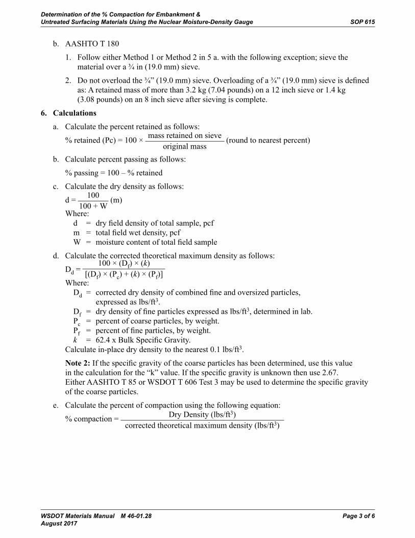
Determination of the % Compaction for Embankment & Untreated Surfacing Materials Using the Nuclear Moisture-Density Gauge SOP 615
WSDOT Materials Manual M 46-01.28 Page 3 of 6 August 2017
b. AASHTOT180
1. Follow either Method 1 or Method 2 in 5 a. with the following exception; sieve the material over a ¾ in (19.0 mm) sieve.
2. Donotoverloadthe¾”(19.0mm)sieve.Overloadingofa¾”(19.0mm)sieveisdefinedas: A retained mass of more than 3.2 kg (7.04 pounds) on a 12 inch sieve or 1.4 kg (3.08 pounds) on an 8 inch sieve after sieving is complete.
6. Calculations
a. Calculate the percent retained as follows:
% retained (Pc) = 100 × mass retained on sieve original mass
(round to nearest percent)
b. Calculate percent passing as follows:
%passing=100–%retained
c. Calculate the dry density as follows:
d = 100 100 + W
(m)
Where: d = dryfielddensityoftotalsample,pcf m = totalfieldwetdensity,pcf W = moisturecontentoftotalfieldsample
d. Calculate the corrected theoretical maximum density as follows:
Dd = 100 × (Df) × (k)
[(Df) × (Pc) + (k) × (Pf)] Where:
Dd = correcteddrydensityofcombinedfineandoversizedparticles, expressed as lbs/ft3. Df = drydensityoffineparticlesexpressedaslbs/ft3, determined in lab. Pc = percent of coarse particles, by weight. Pf = percentoffineparticles,byweight. k = 62.4xBulkSpecificGravity. Calculate in-place dry density to the nearest 0.1 lbs/ft3.
Note2:Ifthespecificgravityofthecoarseparticleshasbeendetermined,usethisvalueinthecalculationforthe“k”value.Ifthespecificgravityisunknownthenuse2.67.EitherAASHTOT85orWSDOTT606Test3maybeusedtodeterminethespecificgravityof the coarse particles.
e. Calculate the percent of compaction using the following equation:
% compaction = Dry Density (lbs/ft3) corrected theoretical maximum density (lbs/ft3)
Determination of the % Compaction for Embankment & SOP 615 Untreated Surfacing Materials Using the Nuclear Moisture-Density Gauge
Page 4 of 6 WSDOT Materials Manual M 46-01.28 August 2017
7. DensityCurveTables
The Materials Testing System (MATS) Density Curve Tables is the WSDOT preferred method for determining the corrected theoretical maximum density.
a. MATScalculatesthecorrectedtheoreticalmaximumdensityinaccordancewithAASHTOT 99 and T 180 ANNEX A1. (Correction of Maximum Dry Density and Optimum Moisture for Oversized Particles) and reports the results in the Density Curve Table.
b. To determine the corrected theoretical maximum density using the Density Curves Table enter the Table at the line corresponding to the % passing or % retained (T 99 & T 180 requires percent retained, T 606 requires percent passing), read across to the column labeled Max this number is the Corrected Theoretical Maximum Density.
8. Report
a. Report the results using one or more of the following:• Materials Testing System (MATS)• WSDOT Form 350-074 and 351-015• Form approved in writing by the State Materials Engineer
b. Report the percent of compaction to the nearest whole number.
WSDOT Materials Manual M 46-01.28 Page 5 of 6 August 2017
Performance Exam ChecklistWSDOT Standard Operating Procedure SOP 615 Determination of the % Compaction for Embankment & Untreated Surfacing Materials Using the Nuclear Moisture-Density Gauge
Participant Name Exam Date
ProcedureElement Yes No1. The tester has a copy of the current procedure on hand?2. All equipment is functioning according to the test procedure, and if required,
hasthecurrentcalibration/verificationtagspresent?
GradationAnalysis 3(A)Method11. Sample Dried to a SSD condition (dried until no visible free moisture present) and
mass recorded?2. Sampleallowedtocoolsufficientlypriortosieving?3. Samplewasshakenbyhandthroughtheappropriatesieveforasufficientperiod
of time?4. Recorded mass of material retained on the appropriate sieve?5. Calculated and recorded percent of material retained and passing the
appropriate sieve?
3(B)Method21. Mass of sample determined prior to washing?2. Materialchargedwithwaterinsuitablecontainerandagitatedtosuspendfines?3. Sampledecantedoverrequiredsieveforasufficientamountoftimewithout
overloading sieve?4. Retained material dried to SSD condition and mass determined?5. Recorded mass of material retained on appropriate sieve?6. Calculated and recorded percent of material retained and passing appropriate sieve?
CorrectionforCoarseParticles7. Appropriate MATS Density Curve Table used to determine the corrected theoretical
maximum density, based on the percent passing or retained on the appropriate sieve?8. All calculations performed correctly?
First Attempt: Pass Fail Second Attempt: Pass Fail
Signature of Examiner

Determination of the % Compaction for Embankment & SOP 615 Untreated Surfacing Materials Using the Nuclear Moisture-Density Gauge
Page 6 of 6 WSDOT Materials Manual M 46-01.28 August 2017
Comments:
WSDOT Materials Manual M 46-01.28 Page 1 of 10 August 2017
WSDOT Test Method T 716Method of Random Sampling for Locations of Testing and Sampling Sites
A. Scope
1. This method outlines the procedure for selecting sampling and testing sites in accordance with accepted random sampling techniques. It is intended that all testing and sampling locations be selected in an unbiased manner based entirely on chance.
2. Testing and sampling locations and procedures are as important as testing. For test results or measurements to be meaningful, it is necessary that the sampling locations be selected at random, typically by use of a table of random numbers. Other techniques yielding a system of randomly selected locations are also acceptable.
B. SummaryofMethodforSelectingRandomTestLocation
• MethodA–DeterminingaRandomLocationforHotMixtureAsphalt(HMA)DensityTests
• MethodB–DeterminingRandomTestLocationforSamplingHMAMix,Aggregates,and Miscellaneous Materials
• MethodC–DeterminingRandomTestLocationforPortlandCementConcrete
• AppendixA–HotMixAsphaltDensityTestLocationsforIrregularPavingAreas
C. ProcedureforDeterminingRandomTest/SamplingLocation
MethodA–SelectionofRandomLocationforHMADensity
1. Stationing
ThismethodoutlinestheprocedurefordeterminingtherandomlocationofHMADensitytesting sites using stationing.
Calculatethelinearfootdistancefortonsspecifiedpersublot(i.e.80or100tonsublots).
Equations:
WSDOT Materials Manual M 46-01.25 July 2016
Page 1 of 10
WSDOT Test Method T 716Method of Random Sampling for Locations of Testing and Sampling Sites
A. Scope1. This method outlines the procedure for selecting sampling and testing sites in accordance
with accepted random sampling techniques. It is intended that all testing and samplinglocations be selected in an unbiased manner based entirely on chance.
2. Testing and sampling locations and procedures are as important as testing. For test resultsor measurements to be meaningful, it is necessary that the sampling locations be selectedat random, typically by use of a table of random numbers. Other techniques yielding a systemof randomly selected locations are also acceptable.
B. SummaryofMethodforSelectingRandomTestLocation• MethodA–Determining a Random Location forHotMixture Asphalt (HMA) Density Tests
• MethodB–Determining Random Test Location for Sampling HMAMix, Aggregates,and Miscellaneous Materials
• MethodC–DeterminingRandomTest Location for Portland Cement Concrete
• AppendixA–Hot Mix Asphalt Density Test Locations for Irregular Paving Areas
C. Procedure for DeterminingRandomTest/SamplingLocation
Method A – SelectionofRandomLocationforHMA Density
1. Stationing
ThismethodoutlinestheprocedurefordeterminingtherandomlocationofHMADensitytesting sites using stationing.
Calculate the linear foot distance for tons specified per sublot (i.e. 80 or 100 ton sublots).
Equations:
𝑆𝑆𝑆𝑆𝑆𝑆𝑆𝑆𝑆𝑆𝑆𝑆𝑆𝑆𝑆𝑆𝑆𝑆𝑆𝑆𝑆𝑆𝑆𝑆 𝑆𝑆𝑆𝑆𝑙𝑙𝑙𝑙𝑙𝑙𝑙𝑙𝑙𝑙𝑙𝑙𝑆𝑆𝑆𝑆ℎ (𝑓𝑓𝑓𝑓𝑆𝑆𝑆𝑆) =𝑆𝑆𝑆𝑆𝑆𝑆𝑆𝑆𝑆𝑆𝑆𝑆𝑆𝑆𝑆𝑆𝑆𝑆𝑆𝑆𝑆𝑆𝑆𝑆 𝑞𝑞𝑞𝑞𝑆𝑆𝑆𝑆𝑞𝑞𝑞𝑞𝑙𝑙𝑙𝑙𝑆𝑆𝑆𝑆𝑞𝑞𝑞𝑞𝑆𝑆𝑆𝑆𝑞𝑞𝑞𝑞 (𝑆𝑆𝑆𝑆𝑆𝑆𝑆𝑆𝑙𝑙𝑙𝑙𝑡𝑡𝑡𝑡)
�𝑤𝑤𝑤𝑤𝑞𝑞𝑞𝑞𝑤𝑤𝑤𝑤𝑆𝑆𝑆𝑆ℎ (𝑓𝑓𝑓𝑓𝑆𝑆𝑆𝑆) 𝑥𝑥𝑥𝑥 𝑤𝑤𝑤𝑤𝑙𝑙𝑙𝑙𝑑𝑑𝑑𝑑𝑆𝑆𝑆𝑆ℎ (𝑓𝑓𝑓𝑓𝑆𝑆𝑆𝑆) 𝑥𝑥𝑥𝑥 2.05 𝑆𝑆𝑆𝑆𝑆𝑆𝑆𝑆𝑙𝑙𝑙𝑙𝑡𝑡𝑡𝑡27 �
a. Use a random number generator (i.e. calculator, computer) or a random numberdetermined by a stopwatch (See Note 1) to enter Table 1. Use the correspondingX value to determine the test station. Anew X value is required for every test.
Note 1: To use the stopwatch method, randomly start and stop the stopwatch 10 or moretimes, then use the decimal part of the seconds as your entry point.
a. Use a random number generator (i.e. calculator, computer) or a random number determined by a stopwatch (See Note 1) to enter Table 1. Use the corresponding X value to determine the test station. A new X value is required for every test.
Note 1: To use the stopwatch method, randomly start and stop the stopwatch 10 or more times, then use the decimal part of the seconds as your entry point.
T 716 Method of Random Sampling for Locations of Testing and Sampling Sites
Page 2 of 10 WSDOT Materials Manual M 46-01.28 August 2017
b. Determine the test station as follows:
Test Station = (sublot length × “X” multiplier) + beginning station of paving (round to the nearest foot)
c. Use a random number generator (i.e. calculator, computer) or a random number determined by a stopwatch (See Note 1) to enter Table 2. Use the corresponding “Y” multipliertodeterminetheoffset.Anew“Y”multiplierisrequiredforeverytest.
d. Determinetheoffsetasfollows:
Offset=(widthofpavementדY”multiplier)(roundtothenearest0.1ft)
Offsetmaybefiguredfromtherightorleftedgeofpavement.TestershallindicateinMATSorapproveddensityformfromwhichedgetheoffsetismeasured.
e. If a tester must move a testing location due to an obstruction of other interference, a new randomnumberfortheoffsetandstationshallbepickedandthelocationrecalculate.Document the new location and the reason the testing location was changed.
Examplefora100tonsublot: Given: Paving width = 12 ft Paving depth = 0.15 ft Beginning Station = 10 + 00 Offsetfromleftedgeofpavement
Calculations:
Page 2 of 10 WSDOT Materials Manual M 46-01.25July 2016
T 716 Method of Random Sampling for Locations of Testing and Sampling Sites
b. Determine the test station as follows:
Test Station = (sublot length × “X” multiplier) + beginning station of paving (round tothe nearest foot)
c. Use a random number generator (i.e. calculator, computer) or a random numberdetermined by a stopwatch (See Note 1) to enter Table 2. Use the corresponding “Y”multiplier to determine the offset. Anew “Y” multiplier is required for every test.
d. Determine the offset as follows:
Offset = (width of pavement × “Y” multiplier) (round to the nearest 0.1 ft)
Offset may be figured from the right or left edge of pavement. Tester shall indicate in MATS or approved density form from which edge the offset is measured.
e. If a tester must move a testing location due to an obstruction of other interference, a newrandom number for the offset and station shall be picked and the location recalculate.Document the new location and the reason the testing location was changed.
Examplefora100tonsublot:Given:
Paving width = 12 ft Paving depth = 0.15 ftBeginning Station = 10 + 00 Offset from left edge of pavement
Calculations:
𝑆𝑆𝑆𝑆𝑆𝑆𝑆𝑆𝑆𝑆𝑆𝑆𝑆𝑆𝑆𝑆𝑆𝑆𝑆𝑆𝑆𝑆𝑆𝑆 𝑆𝑆𝑆𝑆𝑙𝑙𝑙𝑙𝑙𝑙𝑙𝑙𝑙𝑙𝑙𝑙𝑆𝑆𝑆𝑆ℎ =100
�12 𝑥𝑥𝑥𝑥 0.15 𝑥𝑥𝑥𝑥 2.0527 �
= 731.7 𝑆𝑆𝑆𝑆𝑆𝑆𝑆𝑆
Ending Station = (Beginning Station + Sublot length) = (1000 + 731.7) = 17 + 32 Random generated number = X=25, Y=10Beginning Test LocationEnter Table 1 at (25): “X” multiplier = 0.080Enter Table 2 at (10): “Y” multiplier 0.167Testing Station = (732 × 0.080) + 1000 =1058.5 = 10 + 59 (round to the nearest ft) Offset = (12 × 0.167) = 2.00 = 2.0 ft left of pavement edge (round to the nearest 0.1 ft)
Ending Station = (Beginning Station + Sublot length) = (1000 + 731.7) = 17 + 32 Random generated number = X=25, Y=10 Beginning Test Location Enter Table 1 at (25): “X” multiplier = 0.080 Enter Table 2 at (10): “Y” multiplier 0.167 Testing Station = (732 × 0.080) + 1000 =1058.5 = 10 + 59 (round to the nearest ft) Offset=(12×0.167)=2.00=2.0ftleftofpavementedge(round to the nearest 0.1 ft)
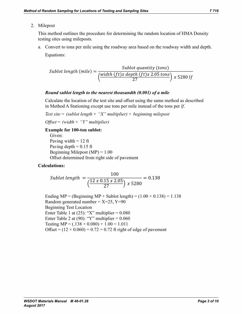
Method of Random Sampling for Locations of Testing and Sampling Sites T 716
WSDOT Materials Manual M 46-01.28 Page 3 of 10 August 2017
2. Milepost
ThismethodoutlinestheprocedurefordeterminingtherandomlocationofHMADensitytesting sites using mileposts.
a. Convert to tons per mile using the roadway area based on the roadway width and depth.
Equations:
WSDOT Materials Manual M 46-01.25 July 2016
Page 3 of 10
Method of Random Sampling for Locations of Testing and Sampling Sites T 716
2. Milepost
ThismethodoutlinestheprocedurefordeterminingtherandomlocationofHMADensitytesting sites using mileposts.
a. Convert to tons per mile using the roadway area based on the roadway width and depth.
Equations:
𝑆𝑆𝑆𝑆𝑆𝑆𝑆𝑆𝑆𝑆𝑆𝑆𝑆𝑆𝑆𝑆𝑆𝑆𝑆𝑆𝑆𝑆𝑆𝑆 𝑆𝑆𝑆𝑆𝑙𝑙𝑙𝑙𝑙𝑙𝑙𝑙𝑙𝑙𝑙𝑙𝑆𝑆𝑆𝑆ℎ (𝑚𝑚𝑚𝑚𝑞𝑞𝑞𝑞𝑆𝑆𝑆𝑆𝑙𝑙𝑙𝑙) =𝑆𝑆𝑆𝑆𝑆𝑆𝑆𝑆𝑆𝑆𝑆𝑆𝑆𝑆𝑆𝑆𝑆𝑆𝑆𝑆𝑆𝑆𝑆𝑆 𝑞𝑞𝑞𝑞𝑆𝑆𝑆𝑆𝑞𝑞𝑞𝑞𝑙𝑙𝑙𝑙𝑆𝑆𝑆𝑆𝑞𝑞𝑞𝑞𝑆𝑆𝑆𝑆𝑞𝑞𝑞𝑞 (𝑆𝑆𝑆𝑆𝑆𝑆𝑆𝑆𝑙𝑙𝑙𝑙𝑡𝑡𝑡𝑡)
�𝑤𝑤𝑤𝑤𝑞𝑞𝑞𝑞𝑤𝑤𝑤𝑤𝑆𝑆𝑆𝑆ℎ (𝑓𝑓𝑓𝑓𝑆𝑆𝑆𝑆)𝑥𝑥𝑥𝑥 𝑤𝑤𝑤𝑤𝑙𝑙𝑙𝑙𝑑𝑑𝑑𝑑𝑆𝑆𝑆𝑆ℎ (𝑓𝑓𝑓𝑓𝑆𝑆𝑆𝑆)𝑥𝑥𝑥𝑥 2.05 𝑆𝑆𝑆𝑆𝑆𝑆𝑆𝑆𝑙𝑙𝑙𝑙𝑡𝑡𝑡𝑡27 � 𝑥𝑥𝑥𝑥 5280 𝑆𝑆𝑆𝑆𝑓𝑓𝑓𝑓
Round sublot length to the nearest thousandth (0.001) of a mileCalculate the location of the test site and offset using the same method as described in Method A Stationing except use tons per mile instead of the tons per lf.
Test site = (sublot length × “X” multiplier) + beginning milepost
Offset = (width × “Y” multiplier)
Examplefor100-tonsublot:Given:Paving width = 12 ft Paving depth = 0.15 ftBeginning Milepost (MP) = 1.00Offset determined from right side of pavement
Calculations:
𝑆𝑆𝑆𝑆𝑆𝑆𝑆𝑆𝑆𝑆𝑆𝑆𝑆𝑆𝑆𝑆𝑆𝑆𝑆𝑆𝑆𝑆𝑆𝑆 𝑆𝑆𝑆𝑆𝑙𝑙𝑙𝑙𝑙𝑙𝑙𝑙𝑙𝑙𝑙𝑙𝑆𝑆𝑆𝑆ℎ =100
�12 𝑥𝑥𝑥𝑥 0.15 𝑥𝑥𝑥𝑥 2.0527 � 𝑥𝑥𝑥𝑥 5280
= 0.138
Ending MP = (Beginning MP + Sublot length) = (1.00 + 0.138) = 1.138 Random generated number = X=25, Y=90Beginning Test LocationEnter Table 1 at (25): “X” multiplier = 0.080Enter Table 2 at (90): “Y” multiplier = 0.060Testing MP = (.138 × 0.080) + 1.00 = 1.011Offset = (12 × 0.060) = 0.72 = 0.72 ft right of edge of pavement
Round sublot length to the nearest thousandth (0.001) of a mile
Calculatethelocationofthetestsiteandoffsetusingthesamemethodasdescribedin Method A Stationing except use tons per mile instead of the tons per lf.
Test site = (sublot length × “X” multiplier) + beginning milepost
Offset = (width × “Y” multiplier)
Examplefor100-tonsublot: Given: Paving width = 12 ft Paving depth = 0.15 ft Beginning Milepost (MP) = 1.00 Offsetdeterminedfromrightsideofpavement
Calculations:
WSDOT Materials Manual M 46-01.25 July 2016
Page 3 of 10
Method of Random Sampling for Locations of Testing and Sampling Sites T 716
2. Milepost
ThismethodoutlinestheprocedurefordeterminingtherandomlocationofHMADensitytesting sites using mileposts.
a. Convert to tons per mile using the roadway area based on the roadway width and depth.
Equations:
𝑆𝑆𝑆𝑆𝑆𝑆𝑆𝑆𝑆𝑆𝑆𝑆𝑆𝑆𝑆𝑆𝑆𝑆𝑆𝑆𝑆𝑆𝑆𝑆 𝑆𝑆𝑆𝑆𝑙𝑙𝑙𝑙𝑙𝑙𝑙𝑙𝑙𝑙𝑙𝑙𝑆𝑆𝑆𝑆ℎ (𝑚𝑚𝑚𝑚𝑞𝑞𝑞𝑞𝑆𝑆𝑆𝑆𝑙𝑙𝑙𝑙) =𝑆𝑆𝑆𝑆𝑆𝑆𝑆𝑆𝑆𝑆𝑆𝑆𝑆𝑆𝑆𝑆𝑆𝑆𝑆𝑆𝑆𝑆𝑆𝑆 𝑞𝑞𝑞𝑞𝑆𝑆𝑆𝑆𝑞𝑞𝑞𝑞𝑙𝑙𝑙𝑙𝑆𝑆𝑆𝑆𝑞𝑞𝑞𝑞𝑆𝑆𝑆𝑆𝑞𝑞𝑞𝑞 (𝑆𝑆𝑆𝑆𝑆𝑆𝑆𝑆𝑙𝑙𝑙𝑙𝑡𝑡𝑡𝑡)
�𝑤𝑤𝑤𝑤𝑞𝑞𝑞𝑞𝑤𝑤𝑤𝑤𝑆𝑆𝑆𝑆ℎ (𝑓𝑓𝑓𝑓𝑆𝑆𝑆𝑆)𝑥𝑥𝑥𝑥 𝑤𝑤𝑤𝑤𝑙𝑙𝑙𝑙𝑑𝑑𝑑𝑑𝑆𝑆𝑆𝑆ℎ (𝑓𝑓𝑓𝑓𝑆𝑆𝑆𝑆)𝑥𝑥𝑥𝑥 2.05 𝑆𝑆𝑆𝑆𝑆𝑆𝑆𝑆𝑙𝑙𝑙𝑙𝑡𝑡𝑡𝑡27 � 𝑥𝑥𝑥𝑥 5280 𝑆𝑆𝑆𝑆𝑓𝑓𝑓𝑓
Round sublot length to the nearest thousandth (0.001) of a mileCalculate the location of the test site and offset using the same method as described in Method A Stationing except use tons per mile instead of the tons per lf.
Test site = (sublot length × “X” multiplier) + beginning milepost
Offset = (width × “Y” multiplier)
Examplefor100-tonsublot:Given:Paving width = 12 ft Paving depth = 0.15 ftBeginning Milepost (MP) = 1.00Offset determined from right side of pavement
Calculations:
𝑆𝑆𝑆𝑆𝑆𝑆𝑆𝑆𝑆𝑆𝑆𝑆𝑆𝑆𝑆𝑆𝑆𝑆𝑆𝑆𝑆𝑆𝑆𝑆 𝑆𝑆𝑆𝑆𝑙𝑙𝑙𝑙𝑙𝑙𝑙𝑙𝑙𝑙𝑙𝑙𝑆𝑆𝑆𝑆ℎ =100
�12 𝑥𝑥𝑥𝑥 0.15 𝑥𝑥𝑥𝑥 2.0527 � 𝑥𝑥𝑥𝑥 5280
= 0.138
Ending MP = (Beginning MP + Sublot length) = (1.00 + 0.138) = 1.138 Random generated number = X=25, Y=90Beginning Test LocationEnter Table 1 at (25): “X” multiplier = 0.080Enter Table 2 at (90): “Y” multiplier = 0.060Testing MP = (.138 × 0.080) + 1.00 = 1.011Offset = (12 × 0.060) = 0.72 = 0.72 ft right of edge of pavement
Ending MP = (Beginning MP + Sublot length) = (1.00 + 0.138) = 1.138 Random generated number = X=25, Y=90 Beginning Test Location Enter Table 1 at (25): “X” multiplier = 0.080 Enter Table 2 at (90): “Y” multiplier = 0.060 Testing MP = (.138 × 0.080) + 1.00 = 1.011 Offset=(12×0.060)=0.72=0.72ftrightofedgeofpavement

T 716 Method of Random Sampling for Locations of Testing and Sampling Sites
Page 4 of 10 WSDOT Materials Manual M 46-01.28 August 2017
Random # X Random # X Random # X Random # X1 0.794 26 0.526 51 0.304 76 0.6172 0.500 27 0.519 52 0.167 77 0.5843 0.393 28 0.446 53 0.308 78 0.5914 0.427 29 0.219 54 0.570 79 0.5635 0.165 30 0.780 55 0.322 80 0.4826 0.821 31 0.574 56 0.491 81 0.4997 0.562 32 0.730 57 0.349 82 0.2278 0.284 33 0.435 58 0.681 83 0.4769 0.704 34 0.338 59 0.858 84 0.258
10 0.988 35 0.515 60 0.716 85 0.22711 0.692 36 0.751 61 0.521 86 0.36412 0.491 37 0.063 62 0.568 87 0.18613 0.769 38 0.269 63 0.168 88 0.79114 0.675 39 0.357 64 0.460 89 0.98515 0.205 40 0.555 65 0.708 90 0.56216 0.187 41 0.837 66 0.453 91 0.75317 0.238 42 0.699 67 0.778 92 0.09718 0.400 43 0.456 68 0.484 93 0.72319 0.263 44 0.730 69 0.609 94 0.21420 0.545 45 0.314 70 0.949 95 0.21521 0.230 46 0.179 71 0.575 96 0.42822 0.700 47 0.152 72 0.263 97 0.64723 0.616 48 0.334 73 0.192 98 0.79424 0.179 49 0.284 74 0.845 99 0.15425 0.080 50 0.819 75 0.095 100 0.964
Random Number - XTable 1
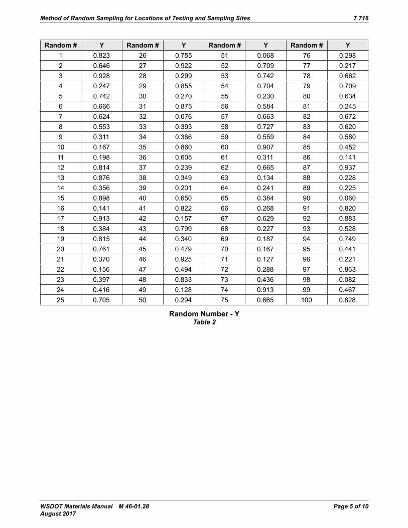
Method of Random Sampling for Locations of Testing and Sampling Sites T 716
WSDOT Materials Manual M 46-01.28 Page 5 of 10 August 2017
Random # Y Random # Y Random # Y Random # Y1 0.823 26 0.755 51 0.068 76 0.2982 0.646 27 0.922 52 0.709 77 0.2173 0.928 28 0.299 53 0.742 78 0.6624 0.247 29 0.855 54 0.704 79 0.7095 0.742 30 0.270 55 0.230 80 0.6346 0.666 31 0.875 56 0.584 81 0.2457 0.624 32 0.076 57 0.663 82 0.6728 0.553 33 0.393 58 0.727 83 0.6209 0.311 34 0.366 59 0.559 84 0.580
10 0.167 35 0.860 60 0.907 85 0.45211 0.198 36 0.605 61 0.311 86 0.14112 0.814 37 0.239 62 0.665 87 0.93713 0.876 38 0.349 63 0.134 88 0.22814 0.356 39 0.201 64 0.241 89 0.22515 0.898 40 0.650 65 0.384 90 0.06016 0.141 41 0.822 66 0.268 91 0.82017 0.913 42 0.157 67 0.629 92 0.88318 0.384 43 0.799 68 0.227 93 0.52819 0.815 44 0.340 69 0.187 94 0.74920 0.761 45 0.479 70 0.167 95 0.44121 0.370 46 0.925 71 0.127 96 0.22122 0.156 47 0.494 72 0.288 97 0.86323 0.397 48 0.833 73 0.436 98 0.08224 0.416 49 0.128 74 0.913 99 0.46725 0.705 50 0.294 75 0.665 100 0.828
Random Number - YTable 2
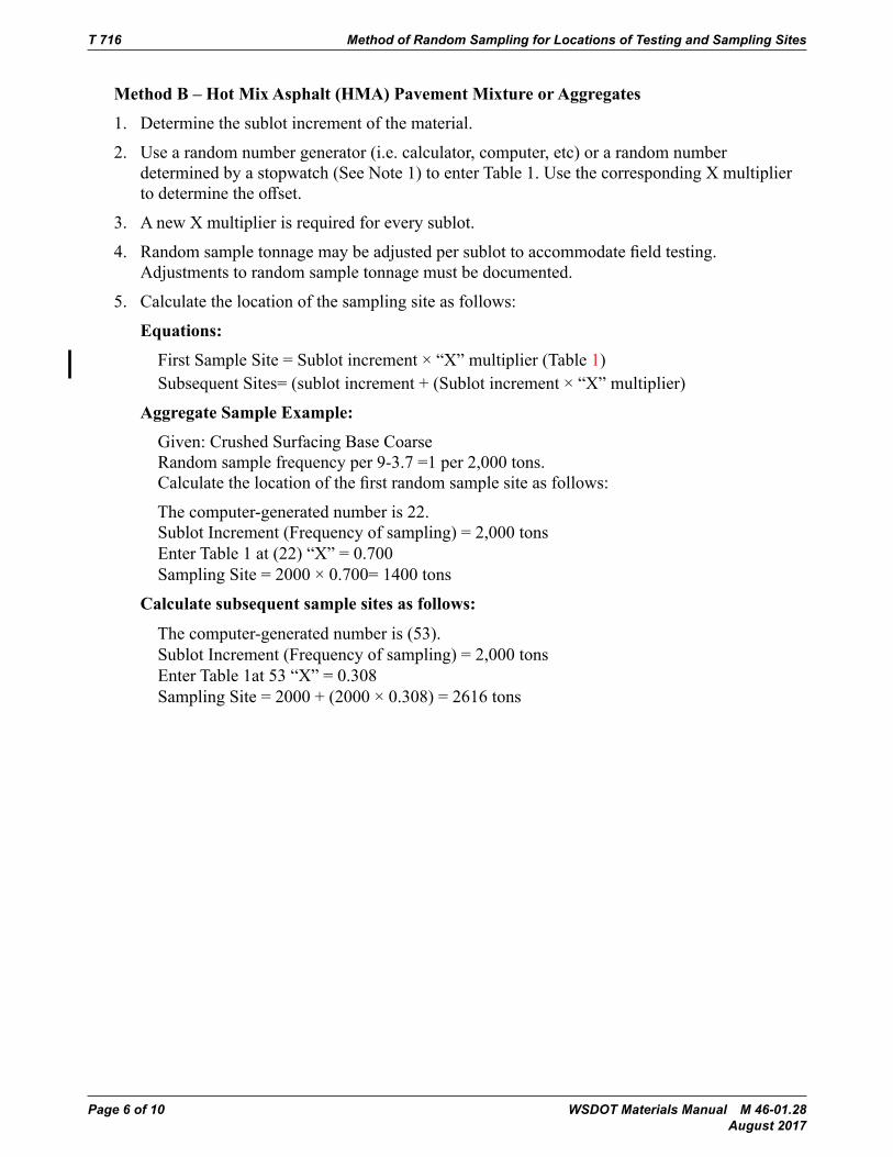
T 716 Method of Random Sampling for Locations of Testing and Sampling Sites
Page 6 of 10 WSDOT Materials Manual M 46-01.28 August 2017
MethodB–HotMixAsphalt(HMA)PavementMixtureorAggregates
1. Determine the sublot increment of the material.
2. Use a random number generator (i.e. calculator, computer, etc) or a random number determined by a stopwatch (See Note 1) to enter Table 1. Use the corresponding X multiplier todeterminetheoffset.
3. A new X multiplier is required for every sublot.
4. Randomsampletonnagemaybeadjustedpersublottoaccommodatefieldtesting.Adjustments to random sample tonnage must be documented.
5. Calculate the location of the sampling site as follows:
Equations:
First Sample Site = Sublot increment × “X” multiplier (Table 1) Subsequent Sites= (sublot increment + (Sublot increment × “X” multiplier)
AggregateSample Example:
Given: Crushed Surfacing Base Coarse Random sample frequency per 9-3.7 =1 per 2,000 tons. Calculatethelocationofthefirstrandomsamplesiteasfollows:
The computer-generated number is 22. Sublot Increment (Frequency of sampling) = 2,000 tons Enter Table 1 at (22) “X” = 0.700 Sampling Site = 2000 × 0.700= 1400 tons
Calculatesubsequentsamplesitesasfollows:
The computer-generated number is (53). Sublot Increment (Frequency of sampling) = 2,000 tons Enter Table 1at 53 “X” = 0.308 Sampling Site = 2000 + (2000 × 0.308) = 2616 tons
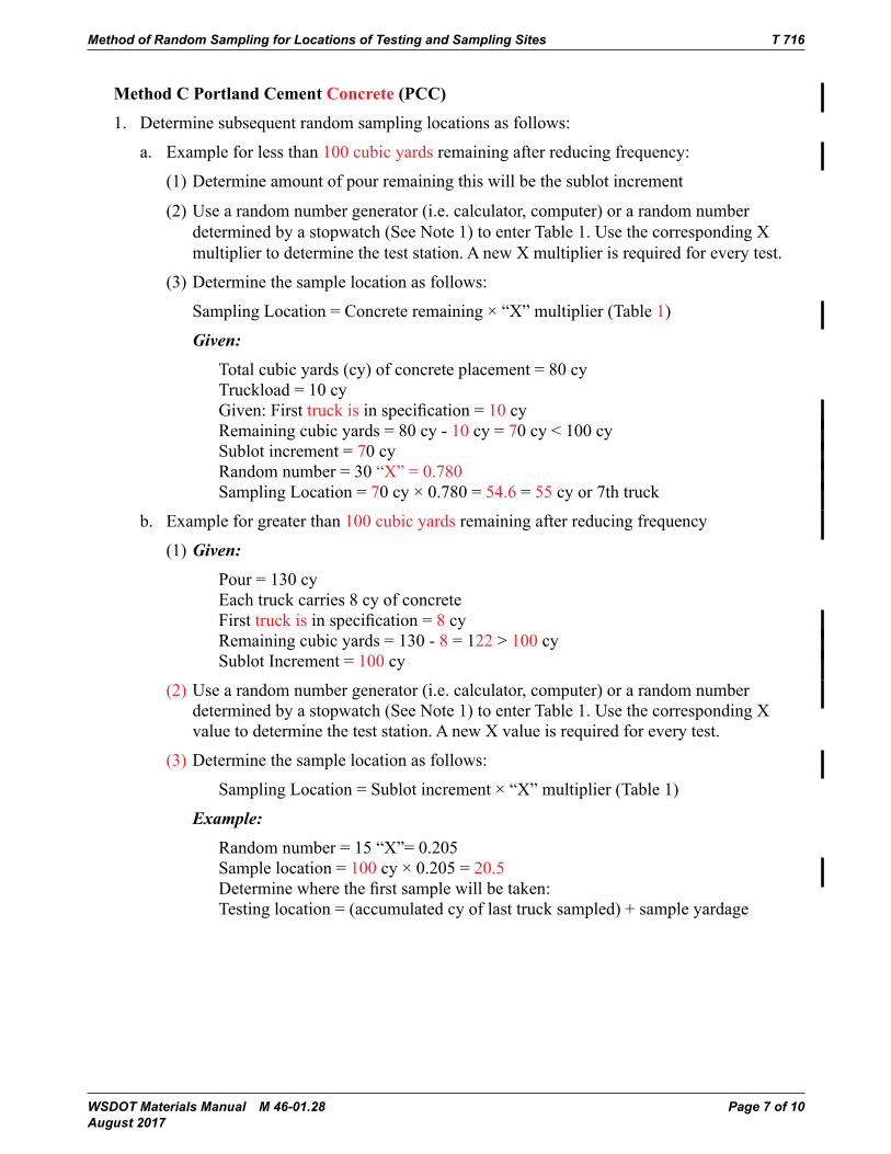
Method of Random Sampling for Locations of Testing and Sampling Sites T 716
WSDOT Materials Manual M 46-01.28 Page 7 of 10 August 2017
MethodCPortlandCementConcrete(PCC)
1. Determine subsequent random sampling locations as follows:
a. Example for less than 100 cubic yards remaining after reducing frequency:
(1) Determine amount of pour remaining this will be the sublot increment
(2) Use a random number generator (i.e. calculator, computer) or a random number determined by a stopwatch (See Note 1) to enter Table 1. Use the corresponding X multiplier to determine the test station. A new X multiplier is required for every test.
(3) Determine the sample location as follows:
Sampling Location = Concrete remaining × “X” multiplier (Table 1)
Given:
Total cubic yards (cy) of concrete placement = 80 cy Truckload = 10 cy Given: First truck isinspecification=10 cy Remaining cubic yards = 80 cy - 10 cy = 70 cy < 100 cy Sublot increment = 70 cy Random number = 30 “X” = 0.780 Sampling Location = 70 cy × 0.780 = 54.6 = 55 cy or 7th truck
b. Example for greater than 100 cubic yards remaining after reducing frequency
(1) Given:
Pour = 130 cy Each truck carries 8 cy of concrete First truck isinspecification=8 cy Remaining cubic yards = 130 - 8 = 122 > 100 cy Sublot Increment = 100 cy
(2) Use a random number generator (i.e. calculator, computer) or a random number determined by a stopwatch (See Note 1) to enter Table 1. Use the corresponding X value to determine the test station. A new X value is required for every test.
(3) Determine the sample location as follows:
Sampling Location = Sublot increment × “X” multiplier (Table 1)
Example:
Random number = 15 “X”= 0.205 Sample location = 100 cy × 0.205 = 20.5 Determinewherethefirstsamplewillbetaken: Testing location = (accumulated cy of last truck sampled) + sample yardage
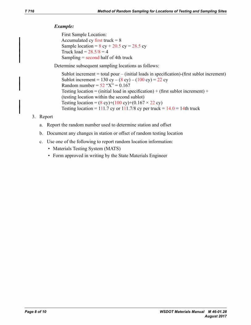
T 716 Method of Random Sampling for Locations of Testing and Sampling Sites
Page 8 of 10 WSDOT Materials Manual M 46-01.28 August 2017
Example:
First Sample Location: Accumulated cy first truck = 8 Sample location = 8 cy + 20.5 cy = 28.5 cy Truck load = 28.5/8 = 4 Sampling = second half of 4th truck
Determine subsequent sampling locations as follows:
Sublotincrement=totalpour–(initialloadsinspecification)-(firstsublotincrement) Sublotincrement=130cy–(8cy)–(100 cy) = 22 cy Random number = 52 “X” = 0.167 Testinglocation=(initialloadinspecification)+(firstsublotincrement)+(testing location within the second sublot) Testing location = (8 cy)+(100 cy)+(0.167 × 22 cy) Testing location = 111.7 cy or 111.7/8 cy per truck = 14.0 = 14th truck
3. Report
a. Reporttherandomnumberusedtodeterminestationandoffset
b. Documentanychangesinstationoroffsetofrandomtestinglocation
c. Use one of the following to report random location information:• Materials Testing System (MATS)• Form approved in writing by the State Materials Engineer
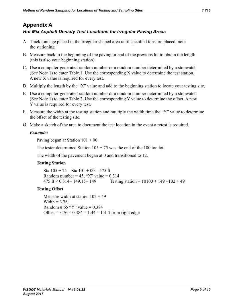
Method of Random Sampling for Locations of Testing and Sampling Sites T 716
WSDOT Materials Manual M 46-01.28 Page 9 of 10 August 2017
Appendix AHot Mix Asphalt Density Test Locations for Irregular Paving Areas
A. Tracktonnageplacedintheirregularshapedareauntilspecifiedtonsareplaced,notethe stationing.
B. Measure back to the beginning of the paving or end of the previous lot to obtain the length (this is also your beginning station).
C. Use a computer-generated random number or a random number determined by a stopwatch (See Note 1) to enter Table 1. Use the corresponding X value to determine the test station. A new X value is required for every test.
D. Multiply the length by the “X” value and add to the beginning station to locate your testing site.
E. Use a computer-generated random number or a random number determined by a stopwatch (SeeNote1)toenterTable2.UsethecorrespondingYvaluetodeterminetheoffset.AnewY value is required for every test.
F. Measure the width at the testing station and multiply the width time the “Y” value to determine theoffsetofthetestingsite.
G. Make a sketch of the area to document the test location in the event a retest is required.
Example:
Paving began at Station 101 + 00.
The tester determined Station 105 + 75 was the end of the 100 ton lot.
The width of the pavement began at 0 and transitioned to 12.
TestingStation
Sta105+75–Sta101+00=475ft Random number = 45, “X” value = 0.314 475 ft × 0.314= 149.15= 149 Testing station = 10100 + 149 =102 + 49
TestingOffset
Measure width at station 102 + 49 Width = 3.76 Random # 65 “Y” value = 0.384 Offset=3.76×0.384=1.44=1.4ftfromrightedge

T 716 Method of Random Sampling for Locations of Testing and Sampling Sites
Page 10 of 10 WSDOT Materials Manual M 46-01.28 August 2017
WSDOT Materials Manual M 46-01.28 Page 1 of 2 August 2017
WSDOT SOP 730Correlation of Nuclear Gauge Densities With Hot Mix Asphalt (HMA) Cores
1. WhenevaluatingHMAcompaction:
1.1 A gauge correlation is required:
a. ForeachcombinationofgaugeandHMAMixDesign(initialJMF).
b. When gauge mode changes (i.e., back scatter to thin layer).
c. When wearing course lift thickness changes per Note 1.
d. When a gauge is recalibrated.
Note 1: For density determined with “Thin Layer Mode,” a layer thickness change of greater than 0.08 feet requires a new correlation. For density determined with "Back Scatter Mode,” a layer thickness change of greater than 0.15 feet requires a new gauge correlation.
1.2 A gauge correlation is not required but may be considered by the Regional Materials Engineer when:
a. Base material changes from the original correlation base (i.e., from a surfacing base to an asphalt base).
b. ThesamegaugeHMAMixDesign(ReferenceMixDesign)combinationareusedonadifferentcontractwithinthesameconstructionyear.
c. WhenJMFhasbeenadjustedinaccordancewithStandard Specifications Section 9-03.8(7)A.
2. Gaugecorrelationisbasedontenin-placeHMAdensitiesandtencorestakenatthesamelocation as the in-place density.
2.1 In-placeHMAdensitiesshallbedeterminedinaccordancewithWSDOTFOPforWAQTCT 355.
2.2 Coresshouldbetakennolaterthanthedayfollowingpavingandbeforetraffichasbeen allowed on roadway. Correlation cores are not required to be taken at record density locations. Therefore, a site outside the traveled way should be considered for worker safety, as long as the lift thickness matches that of the plan lift thickness of the record density locations.
Note 2: If a core becomes damaged, it shall be eliminated from the average.
Note 3:CoresmaybetakensoonerthanthedayafterpavingiftheHMAiscooledtopreventdamage during coring and removal of cores. Water, ice, or dry-ice may be used to cool the pavement. Another method of cooling that may be used is substitution of nitrogen gas or CO2fordrillingfluids.

SOP 730 Correlation of Nuclear Gauge Densities With Hot Mix Asphalt (HMA) Cores
Page 2 of 2 WSDOT Materials Manual M 46-01.28 August 2017
3. Obtain a pavement core from each of the test sites in accordance with WSDOT SOP 734. The core shall be taken in the nuclear gauge footprint.
3.1 For either gauge mode, back scatter or thin layer, locate the core in the approximate center of the nuclear gauge footprint. If the core thickness exceeds the plan pavement thickness by more than 0.04 feet, then the core shall be saw cut to the plan thickness prior to performing density testing. If a core thickness is less than the plan thickness by more than 0.04 feet, it shall be eliminated from the average.
4. BulkSpecificGravity(Gmb) of core shall be determined in conformance with WSDOT FOP for AASHTOT166BulkSpecificGravityofCompactedHotMixAsphalt(HMA)UsingSaturatedSurface-Dry Specimens.
Calculate core density as follows, round to the nearest 0.1 pcf:
Core Density = Gmb × 62.245 pcf
Calculate gauge correlation factor as follows:
Density Ratio = (core density)
(nuclear gauge density) Round Density Ratio to the nearest 0.001
Gauge correlation factor = (Sum of ratios)
(number of cores)5. Gauge Correlation Factor shall be determined to 0.001.
6. Report the Gauge Correlation Factor using MATS or DOT Form 350-112.
WSDOT Materials Manual M 46-01.28 Page 1 of 4 August 2017
WSDOT SOP 734 Sampling Hot Mix Asphalt After Compaction (Obtaining Cores)
1. Scope• ThismethoddescribestheprocessforobtainingHotMixAsphalttestcoresforLaboratory
testing after compaction has been completed. Cores may range in size from 2 in to 12 in
2. SignificanceandUse• Samples obtained in accordance with the procedure given in this practice may be used for
measuring pavement thickness, density, and acceptance testing.• When cores are used to determine nuclear gauge correlation, refer to WSDOT SOP 730.•Whencoresareusedtodeterminepavementdensity,theBulkSpecificGravity(Gmb) isdeterminedaccordingtoWSDOTFOPforAASHTOT166.
•WhencoresareusedforforensictestingofHMA,refertoSOP737“ProcedurefortheForensicTestingofHMAFieldCores”todeterminetherequirednumberandsizeofcores.
3. Apparatus• CoreDrillMachine–ACoreDrillMachineofsufficienthorsepoweranddepthtominimizedistortionofthecompactedcoresofHotMixAsphalt.
• CoreBit–Thecuttingedgeofthecoredrillbitshallbeofhardenedsteelorothersuitablematerial with diamond chips embedded in the metal cutting edge or as recommended by the core drill bit manufacturer. Typically the core drill bit should have an inside diameter of 4” ± 0.25” (100 mm ± 6 mm) or 6” ± 0.25” (150 mm ± 6 mm), these core bit dimensions are agency preferred alternatives. Suitable larger and smaller diameter core bit alternatives shall be employed as required by the agency.
• Tools–Corelayersmaybeseparatedusingasaworothersuitabledevicewhichprovidesaclean smooth surface and does not damage the core.
• RetrievalDevice(Optional)–Theretrievaldeviceusedforremovingcoresamplesfromholesmust preserve the integrity of the core. The device may be a steel rod of suitable length and withadiameterthatwillfitintothespacebetweenthecoreandthepavementmaterial.Theremay be a 90 degree bend at the top to form a handle and a 90 degree bend at the bottom, approximately 2 in (50 mm) long, forming a hook to assist in the retrieval of the core or other suitable device.
4. Safety
This standard does not purport to address all of the safety concerns, associated with its use. It is the responsibility of the user of this standard operating procedure to establish a pre activity safety plan prior to use.
SOP 734 Sampling Hot Mix Asphalt After Compaction (Obtaining Cores)
Page 2 of 4 WSDOT Materials Manual M 46-01.28 August 2017
5. TestSiteLocation• The quantity of cores to be obtained shall be determined by the test procedure to be
performed or agency requirements. Refer to WSDOT SOP 730 when taking correlation cores.• Determine the location of the core(s) as required by the agency.
6. Procedure• ForfreshlyplacedHotMixAsphaltmaterials,thecoreshallbetakenwhenthematerialhashadsufficientamountoftimetocooltopreventdamagetothecore.
• Pavement may be cooled to expedite the removal of the core by the following methods; water, ice water, ice, or dry ice or liquid nitrogen.
• Place the coring machine and core bit over the selected location.•KeepthecorebitperpendiculartotheHotMixAsphaltsurfaceduringthecoringprocess. Note1: If any portion of the coring machine shifts during the operation, the core may break
or distort.• Constant downward pressure should be applied on the core bit. Failure to apply constant
pressure, or too much pressure, may cause the bit to bind or distort the core.• Continue the coring operation until the desired depth is achieved.• If necessary, use a retrieval device to remove the core.• Clearlyidentifythecoreslocationandoffsetwithoutcausingdamage(i.e.,lumbercrayon
or grease pencil). Note2: If the core is damaged to a point that it cannot be used for its intended purpose,
a new core shall be obtained within 6 in of the original location.
7. FillingCoreHoles•Whennecessary,theholemadefromthecoringoperationshallbefilledwithamaterialthatwillnotseparatefromthesurroundingmaterial.IfHotMixAsphaltisavailableandused,itshall be compacted into the hole. A ready mix concrete or fast set grout product may be used inlieuofaHotMixAsphalt.Ablackdyecanbeusedtocolorthegroutondriving surface.
• Priortobackfillingacoreholeonabridgedeck,ensurethattheholeandsidewallsaredryenough to bond with the sealant before applying.
• Acceptable sealants include; asphalt binder or any waterproof sealant designed for asphalt applications as stated by the manufacturer.
• Apply sealant to bottom surface and side walls of core hole as needed.• BackfillthecoreholewithHotMixAsphalt,coldmixasphalt,readymixconcreteorgrout
and compact as needed.
Sampling Hot Mix Asphalt After Compaction (Obtaining Cores) SOP 734
WSDOT Materials Manual M 46-01.28 Page 3 of 4 August 2017
8. TransportingCores• Transport cores in a suitable container(s) that prevents damage from jarring, rolling, hitting
together, and/or impact with any object.• Prevent cores from freezing or excessive heat above 130º F (54º C), during transport. Note1: In extreme ambient temperature conditions, cores should be placed in water
during transport.• If the core is damaged in transport to a point it can not be utilized for its intended purpose
the core will not be used.
9. SeparateTheLayers• When necessary, separate the lifts or layers of pavement courses by using a water cooled saw
to cut the core on the designated lift line or separate by other suitable methods that will not damage the lifts or layers to be tested.
Note4: Liftlinesareoftenmorevisiblebyrollingthecoreonaflatsurfaceand/orsurfacedrying the core.
10.LengthDetermination
Measurethethicknessofthedesignatedlifttothenearest0.01’or⅛”accordingtoWSDOTTestMethod 720.
11. Report
Core information shall be reported on standard agency forms and should include the following information.
• The date the cores were obtained• Paving date• Contract number• Project title• Location of test• The lift being evaluated• Type of material being evaluated• Mix Design Lab Number•Averagethicknessofeachcore(tothenearest0.01’or⅛“)• Average Theoretical Maximum Density

SOP 734 Sampling Hot Mix Asphalt After Compaction (Obtaining Cores)
Page 4 of 4 WSDOT Materials Manual M 46-01.28 August 2017
This page intentionally left blank.