maximum power point tracker design - · pdf fileinternship report – hs bochum solar...
TRANSCRIPT
Hochschule Bochum
SolarCar Projekt
German Jordanian University
School of Applied Technical Sciences
Internship Report March – August 2011
Maximum Power Point Tracker Design Name: Mahmood Shubbak Student ID: 2007102028
Internship Report – HS Bochum Solar Car Project (MPPT Design) ‐ Mahmood Shubbak 2/29
List of Contents Hochschule Bochum: Portrait ………………………………………………………………………. 3 SolarCar Projekt …………………………………………………………………………………………… 4
Solar Energy: Solar Thermal Electricity ……………………………………………………………………………… 7 Photovoltaic Energy …………………………………………………………………………………….. 7 PV Characteristic Curve .……………………………………………………………………………. 10 Factors of PV Panel Performance ……………………………………………………………… 11 Maximum Power Point ………………………………………………………………………………….. 13
MPPT Design: Purpose ……………………………………………………………………………………………………….. 17 General Description …………………………………………………………………………………….. 17 Details DC‐DC Converters ……………………………………………………………………………………… 17 Current and Voltage Sensing …………………………………………………………………….. 19 Maximum Power Point Tracking algorithms ……………………………………………… 21 Other Circuit Partitions: Status LED ………………………………………………………………………………………………. 22 Power Supply Voltage Regulator ……………………………………………………………. 23
References …………………………………………………………………………………………………. 24
APPENDIX A: Circuit Schematic….……………………………………………………………….. 25 APPENDIX B: Program Code ……………………………………………………………………..… 28

Internship Report – HS Bochum Solar Car Project (MPPT Design) ‐ Mahmood Shubbak 3/29
Hochschule Bochum
Portrait [source: Hochschule Bochum Website]
The Hochschule Bochum - Bochum University of Applied
Sciences, founded in 1972, is a modern university of
applied sciences, specialising in technology and
business. Its long tradition of offering academic fast-
track, student-centred undergraduate and postgraduate
programmes that enjoy an unchallenged reputation in
the professional world.
The long-term close links to industry, business, service providers, and many other
organisations in the region of the central Ruhrgebiet (Ruhr area) gives the Hochschule
Bochum the edge.
Since the professors and lecturers at the Hochschule
Bochum all worked for years in their core areas, the
university has built and maintains close partnerships with
the real world of business and engineering.
This relationship has resulted in research partnerships, joint development projects, and
ample opportunities for students. To date the six departments, Architecture, Civil
Engineering and Surveying and Geo Computer Science, Mechatronics and Mechanical
Engineering, Electrical Engineering and Computer Science and Business and Management
offer 23 such undergraduate and postgraduate pathways.
Partner companies often act as the inspiration for applied
research and development work at the Hochschule
Bochum, raising questions and problems which act as the
focus for student theses.
Our students actively participate in industrial research and problem-solving. The Transfer
Prizes, donated by prestigious companies from the region (Klaus Steilmann, Adam Opel
AG, Siemens AG, VEBA Immobilien, Deutsche Bank AG, HDI, Stadtparfümerie Pieper,
Johann Phillipps) are awarded for outstanding student achievement. For many award-
winning students, this proven track record of innovation is the key to successful careers.

Internship Report – HS Bochum Solar Car Project (MPPT Design) ‐ Mahmood Shubbak 4/29
SolarCar Projekt [source: Hochschule Bochum Website] Mit der Energie der Sonne
Seit 1999 werden von Studierenden der Hochschule Bochum Solarfahrzeuge entwickelt,
die ausschließlich mit der Energie der Sonne angetrieben werden. Der Ursprung findet sich
an der Partnerhochschule, der London South Bank University. 2001 fuhr der mit deutschen
Studenten in London entwickelte Mad Dog III bei der World Solar Challenge(WSC) in
Australien mit.
Das in den Jahren 2001 bis 2003 entwickelte Fahrzeug "Hans Go!" erzielte bei der WSC,
der inoffiziellen Weltmeisterschaft der Solarmobile, im Jahr 2003 den 5-ten Platz und im
Jahr 2005 den 8-ten Platz. Der Technical Innovation Award für das implementierte
Bluetooth-Telemetriesystem, verliehen von der "Australia's Commonwealth Scientific and
Industrial Research Organisation" (CSIRO), belegte schon 2003 das extrem hohe Niveau
der Entwicklungen.
Die schönsten Solarfahrzeuge der Welt
SolarWorld No. 1, von 2005 bis 2007 geplant und gebaut, belegte bei der World Solar
Challenge 2007 den 4-ten Platz und wurde mit dem Award für das "Beste Design"
ausgezeichnet. In den Jahren 2008 und 2010 erreichte der Sonnenwagen den 3. Platz bei
der North American Solar Challenge und wurde für innovative und exzellente Technik in
den Bereichen Mechanik und Elektrotechnik prämiert. Das schönste Solarcar der Welt steht
also an der Hochschule Bochum, wenn es nicht gerade unterwegs ist in Australien oder
Amerika. Die Studierenden, Mitarbeiter und Professoren aus allen Fachbereichen der
Hochschule Bochum präsentieren voller Stolz dieses Musterbeispiel von Energieeffizienz.
Sechs Quadratmeter Solarzellen produzieren bei intensivem Sonnenschein die Leistung, die
ein Haartrockner benötigt. SolarWorld No. 1 fuhr damit über 3000 km unter der Sonne
Australiens durchschnittlich 73 km/h. Die Spitzengeschwindigkeit liegt bei 120 km/h. Ein
Projekt, das alle Facetten des Ingenieurberufes beleuchtet: Teamarbeit,
Projektmanagement, interkulturelle Perspektiven und nicht zuletzt die Faszination
moderner Technik. Dazu gehört die Herausforderung, durch effiziente Energienutzung ein
Fahrzeug komplett mit regenerativer Energie emissionsfrei zu betreiben.
Der BOcruiser, gebaut für die Global Green Challenge 2009 in Australien, geht den
nächsten konsequenten Schritt in Richtung Alltagstauglichkeit. Mit vier Rädern, zwei davon
mit selbst ent- und gewickelten Radnabenmotoren angebtrieben, und PKW-typischen
Abmessungen zeigt die Bochumer SolarCar-Manufaktur das innovative Potential der
Hochschule. 2010 gewinnt der BOcruiser die European Solar Challenge.
Die Zukunft
Für die Teilnahme an der World Solar Challenge im Oktober 2011 in Australien wird ein
neues Fahrzeug entwickelt und gebaut werden, das in der Tradition von SolarWorld No.1
und BOcruiser stehen wird: Ingenieurkunst vom Feinsten. Ziel ist es, nicht als Erster über
die Ziellinie zu gehen, sondern am Wettbewerb mit dem innovativsten und damit besten
Internship Report – HS Bochum Solar Car Project (MPPT Design) ‐ Mahmood Shubbak 5/29
Fahrzeug teilzunehmen und der Weltöffentlichkeit erneut zu beweisen, was "made in
Germany" bedeutet.
Das SolarCar-Projekt an der Hochschule Bochum
Didaktischer und wissenschaftlicher Hintergrund
Das SolarCar-Projekt begann Mitte der neunziger Jahre an der Partnerhochschule London
South Bank University (LSBU). Von 1999 bis 2005 wurde es von der Hochschule Bochum
und der London South Bank University als gemeinsames Lehrforschungsprojekt betrieben.
Nach dem Wechsel von Prof. Dr Mike Duke zur University of Waikato, Hamilton, New
Zealand, wird es ausschließlich als Problem Based Learning Lehrforschungsprojekt an der
Hochschule Bochum mit Studierenden aus allen Fachbereichen durchgeführt. Problem
Based Learning (PBL) bedeutet eine auf den Lernenden zentrierte Lehrmethode. Dem
Studierenden wird schrittweise immer mehr Verantwortung für den eigenen Wissensaufbau
übertragen. Dies führt zu unabhängig Lernenden, die für ihren Lernerfolg selbst
verantwortlich sind und sich eigenständig fortbilden. Die Motivation fördert entscheidend
eine komplexe, unstrukturierte Problemstellung aus der Realität, für die
fachbereichsübergreifende Lösungsansätze im Team entwickelt werden müssen. Die
studentische Teamleitung verantwortet alle konkreten Entwicklungsschritte und plant den
Einsatz der notwendigen Ressourcen. Die Lehrenden agieren als Trainer, sorgen für die
notwendige Infrastruktur und Materialien und begleiten die Studierenden durch das
Vorhaben. Prozessnahe Reflektionen und ein konkreter Abschluss mit Selbst- und
Fremdbeurteilung beenden die Durchführung jeder Phase des Projekts. Die wahlfreie
Lehrveranstaltung "Entwicklung von solarbetriebenen Fahrzeugen" gehört zum festen
Bestandteil des Ausbildungsprogramms der Hochschule Bochum.
Veröffentlichungen:
- Saalmann, S.; Gochermann, H.; Pautzke, F.; How to Build a Car Powered by Nothing
More than the Sun, Conference Publication of the "6th International Workshop on Research
and Education in Mechatronics REM 2005", Annecy, France, 2005.
- Alstadt, S.; Duke, M.D.; Pautzke, F.; Solar Car Project "Problem-Based Learning at FH
Bochum and London SBU, Conference Publication of the "6th International Workshop on
Research and Education in Mechatronics REM 2005", Annecy, France, 2005.
- Pautzke, F.; Biesenbach, R. Problem-Based Learning Project for REM Network
Universities, Conference Publication of the "6th International Workshop on Research and
Education in Mechatronics REM 2005", Annecy, France, 2005.
- Beese, E., Saalmann, S. Aerodynamikkonzept des Solarrennwagens der Hochschule
Bochum Fahrzeug-Aerodynamik, Haus der Technik, München 2.-3. Juli 2008
- Pautzke, F.; Spychalski, S. 3000 Kilometer mit der Energie der Sonne Projekt SolarCar
an der Hochschule Bochum, Berichte aus dem IFW der Leibnitz Universität Hannover, Band
03/2008, Herausgeber Denkena, B., ISBN 978-3-939026-74-7, 2008, S. 99 - 123.

Internship Report – HS Bochum Solar Car Project (MPPT Design) ‐ Mahmood Shubbak 6/29
Internship Report – HS Bochum Solar Car Project (MPPT Design) ‐ Mahmood Shubbak 7/29
Solar Energy The Sun is the major source of energy on the earth; even other energy sources such as wind and petroleum… etc. are directly or indirectly related to it.
Solar Energy has many advantages such as: 1. It is a clean Energy that doesn’t make any environmental pollution. 2. It is a renewable source of energy. 3. Safety. 4. Low Maintenance Cost.
The main disadvantage of solar energy systems is their high initial cost.
There are two basic methods to generate electrical energy from sunlight:
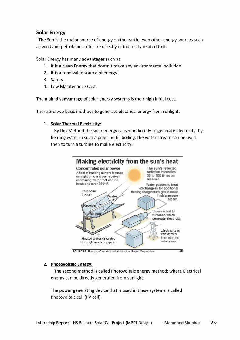
1. Solar Thermal Electricity: By this Method the solar energy is used indirectly to generate electricity, by heating water in such a pipe line till boiling, the water stream can be used then to turn a turbine to make electricity.
2. Photovoltaic Energy: The second method is called Photovoltaic energy method; where Electrical energy can be directly generated from sunlight.
The power generating device that is used in these systems is called Photovoltaic cell (PV cell).
Internship Report – HS Bochum Solar Car Project (MPPT Design) ‐ Mahmood Shubbak 8/29
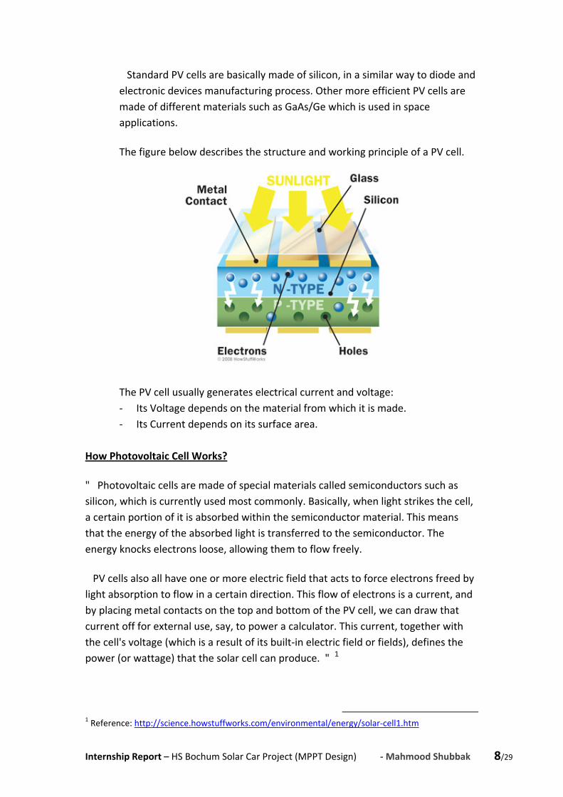
Standard PV cells are basically made of silicon, in a similar way to diode and electronic devices manufacturing process. Other more efficient PV cells are made of different materials such as GaAs/Ge which is used in space applications.
The figure below describes the structure and working principle of a PV cell.
The PV cell usually generates electrical current and voltage: ‐ Its Voltage depends on the material from which it is made. ‐ Its Current depends on its surface area.
How Photovoltaic Cell Works?
" Photovoltaic cells are made of special materials called semiconductors such as silicon, which is currently used most commonly. Basically, when light strikes the cell, a certain portion of it is absorbed within the semiconductor material. This means that the energy of the absorbed light is transferred to the semiconductor. The energy knocks electrons loose, allowing them to flow freely.
PV cells also all have one or more electric field that acts to force electrons freed by light absorption to flow in a certain direction. This flow of electrons is a current, and by placing metal contacts on the top and bottom of the PV cell, we can draw that current off for external use, say, to power a calculator. This current, together with the cell's voltage (which is a result of its built‐in electric field or fields), defines the power (or wattage) that the solar cell can produce. " 1
1 Reference: http://science.howstuffworks.com/environmental/energy/solar‐cell1.htm
Internship Report – HS Bochum Solar Car Project (MPPT Design) ‐ Mahmood Shubbak 9/29
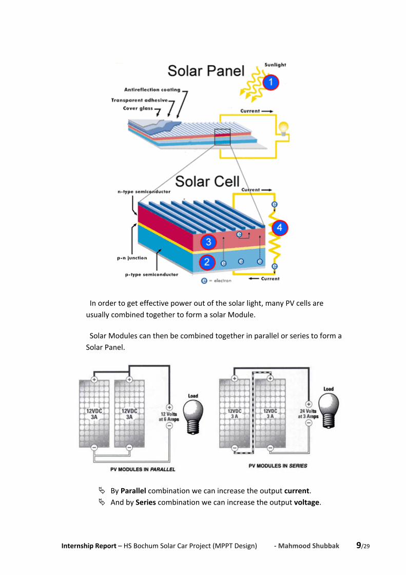
In order to get effective power out of the solar light, many PV cells are usually combined together to form a solar Module.
Solar Modules can then be combined together in parallel or series to form a Solar Panel.
By Parallel combination we can increase the output current. And by Series combination we can increase the output voltage.

Internship Report – HS Bochum Solar Car Project (MPPT Design) ‐ Mahmood Shubbak 10/29
Combining solar panels together we get a Solar Array, as shown in the previous figure.
PV Characteristic Curve: The characteristic curve of the PV Panel is very similar to that of the electronic diode.
In the graph below we can see the Current‐Voltage relation in such a PV solar panel, (for a specific temperature and irradiation).

Internship Report – HS Bochum Solar Car Project (MPPT Design) ‐ Mahmood Shubbak 11/29
It is obvious that the electric current generated by the cell is constant until reaching the high voltages, where it is rapidly damped to zero.
To simulate the behavior of a PV panel, we need a circuit model that has the same electric characteristics.
The simplest PV electric model is shown in the figure below.
It basically consists of dc current source in parallel with electronic diode.
Factors of PV Panel Performance:
There are three main factors that affect the PV panel behavior, and change its characteristic curve, which are: the Load Resistance, the Sunlight Intensity and the Temperature.
Below we will summarize each factor and its effect on the PV Panel behavior.
1. Load Resistance:
The Electric Energy, generated from such a PV Panel can be used either directly by connecting the Panel to a load resistance, or it can be stored in a battery.
In both cases the voltage at which the Panel operates, is determined by the load resistance or the battery bank voltage.
For example: if we used the PV panel to store energy in a 12 V battery, the panel will be forced to operate at 12 V.
2. Sunlight Intensity:
Sunlight Intensity is a key factor which affects the PV panel behavior.
The greater sunlight intensity exists, the larger current is generated by the panel for the same voltage; that means a greater power.

Internship Report – HS Bochum Solar Car Project (MPPT Design) ‐ Mahmood Shubbak 12/29
This effect can be seen clearly in the following graph:
3. Temperature:
The third factor is the cell temperature; when the cell temperature increases the PV panel becomes less efficient, since the highest operating voltage decreases.
This effect is shown in the following graph:

Internship Report – HS Bochum Solar Car Project (MPPT Design) ‐ Mahmood Shubbak 13/29
Maximum Power Point The Electric Power is defined as the rate of electric energy transferred by a circuit. Mathematically it is calculated for DC resistive circuits using Joule's law:
P V I For the PV Panel we can figure out the generated electric power using Joule's law, to get the following power curve:
We can notice that at the operating point of approximately 18 V, we have a peak value of electric power. Imagine that we are using the solar panel to charge battery of 12 V, the panel will be forced to operate at the same voltage (12V), that means the power generated from it will be, as fixed in the graph, 40 Watts, which is less than the maximum possible power of approximately 60 Watts. [5] In another words, if we connect the battery directly to the solar panel, we will lose electric power.

Internship Report – HS Bochum Solar Car Project (MPPT Design) ‐ Mahmood Shubbak 14/29
To solve this problem, and to take advantage of all possible power, we need to use some interfacing circuitry between the solar panel and the battery, by which the battery can be charged with the maximum power point of the panel.
FFiirrsstt SStteepp:: This circuitry must force the panel to operate at its peak power point (which is in our example here about 18V and 3.3 Amps). The total generated power will be approximately 60 Watts (MPP)
SSeeccoonndd SStteepp:: The circuitry after that must convert this dc voltage from 18V to the battery voltage level of 12V, keeping the electric power constant (= 60 Watts). This can happen by increase the electric current. And can be done by a high efficient electric converter. This method can be sufficient if the PV Panel has a fixed behavior, which is not the normal case. As we mentioned previously, the PV panel is affected by another two factors: the Temperature and the Sunlight Intensity, and each one of them can change the Panel characteristic curve and the maximum power point consequently. Look at the following figure:

Internship Report – HS Bochum Solar Car Project (MPPT Design) ‐ Mahmood Shubbak 15/29
For this reason, the circuitry, that we need, must also determine the maximum power point and track it as these factors change (TThhiirrdd SStteepp). The circuitry that does all these functions is called Maximum Power Point Tracker (MPPT). To understand the work principle of MPPT, look at the following block diagram:
It represents the main components of the MPPT circuit, which are:
1. Buck converter: that is basically a step down dc‐dc converter. 2. Sensors: to measure battery current and voltage (the actual power). 3. Microcontroller: to track the maximum power point using a specific
algorithm.
AAnnootthheerr ccaassee::
When the battery voltage is larger than the solar panel voltage, (for example if we have a solar panel that provides of approximately 50 volts, and we want to use it to charge a battery of 100 volts).
In this case we need to determine the MPP, operate the panel on it, and convert the panel voltage up to the battery level, using a step up dc‐dc converter (Boost Converter).

Internship Report – HS Bochum Solar Car Project (MPPT Design) ‐ Mahmood Shubbak 16/29
In both cases, the MPPT must consist of a Converter, Sensors and a Microcontroller.
The MPPT itself is actually a battery charge controller for solar applications.
Up to this point we can figure out that a PPhhoottoovvoollttaaiicc SSyysstteemm consists of: The Power Source (Solar Irradiance from the Sun) activates the photovoltaic panel, which generates electric power that is controlled by a charge controller.
This power is used after that to charge electric battery, which operates electric devices. Look at the following diagram.
Internship Report – HS Bochum Solar Car Project (MPPT Design) ‐ Mahmood Shubbak 17/29
MPPT Design:
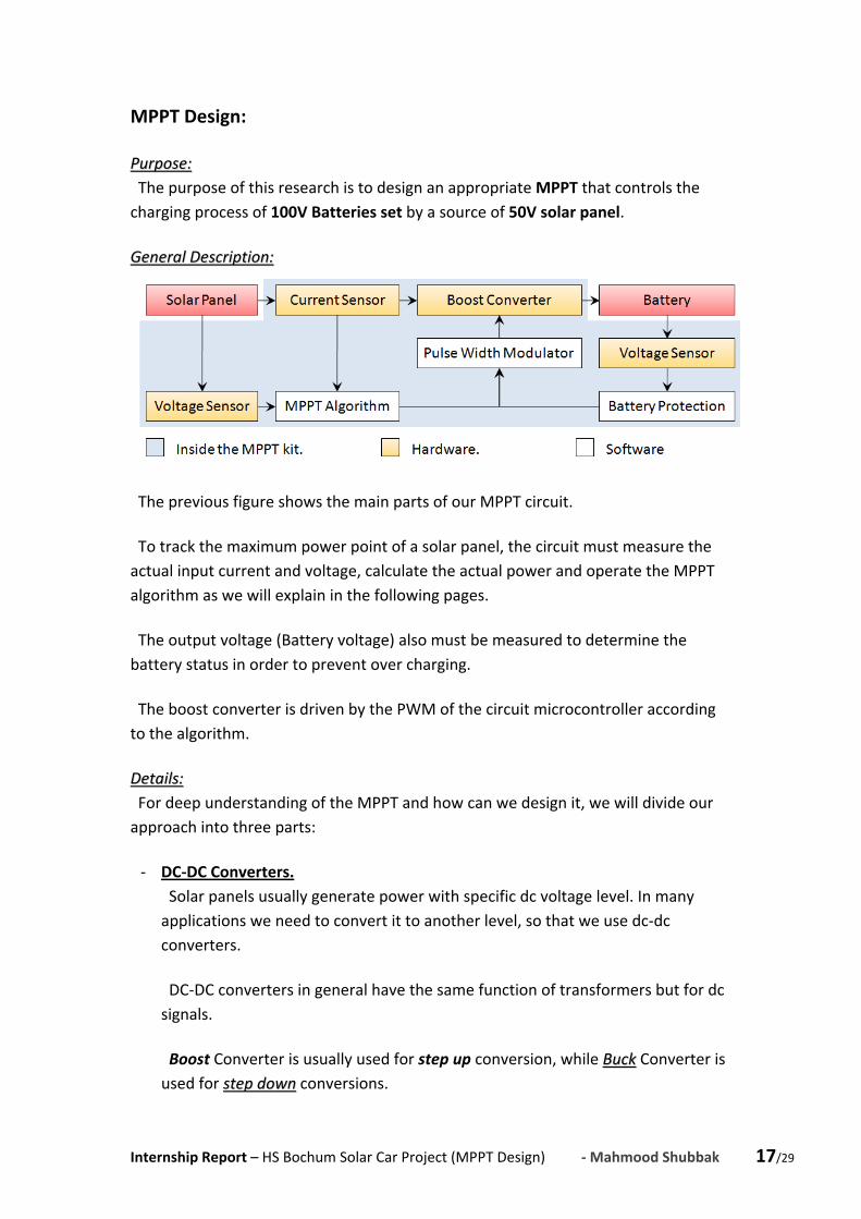
PPuurrppoossee:: The purpose of this research is to design an appropriate MPPT that controls the charging process of 100V Batteries set by a source of 50V solar panel.
GGeenneerraall DDeessccrriippttiioonn::
The previous figure shows the main parts of our MPPT circuit.
To track the maximum power point of a solar panel, the circuit must measure the actual input current and voltage, calculate the actual power and operate the MPPT algorithm as we will explain in the following pages.
The output voltage (Battery voltage) also must be measured to determine the battery status in order to prevent over charging.
The boost converter is driven by the PWM of the circuit microcontroller according to the algorithm.
DDeettaaiillss:: For deep understanding of the MPPT and how can we design it, we will divide our approach into three parts:
‐ DC‐DC Converters. Solar panels usually generate power with specific dc voltage level. In many applications we need to convert it to another level, so that we use dc‐dc converters.
DC‐DC converters in general have the same function of transformers but for dc signals.
Boost Converter is usually used for step up conversion, while BBuucckk Converter is used for sstteepp ddoowwnn conversions.

Internship Report – HS Bochum Solar Car Project (MPPT Design) ‐ Mahmood Shubbak 18/29
DC‐DC converters basically consist of two power storing elements (an inductor and a capacitor), and a high speed electric switch (which is usually an electronic transistor).
The important thing that we need to know about the dc‐dc converters behavior is that they convert the dc voltage from one level to another by a specific gain (or factor) directly related to the duty cycle supplied to their switches from a Pulse Width Modulator PWM.
That means we can change the operation point by varying this duty cycle.
For more information you can see a full explanation of buck, boost and also other types of dc‐dc converters on the Jaycar Electronics attached paper [Reference 3].
In our research here we need a boost converter to step the 50V solar voltage up to 100V to charge the batteries.
The circuit below represents the simulation test for our boost converter by Multisim software.
And below you can see the simulation results for this circuit:

Internship Report – HS Bochum Solar Car Project (MPPT Design) ‐ Mahmood Shubbak 19/29
Note that the circuit reaches the 100V output level in less than 2ms, which seems quite good.
The component values we used here where:
LL11 == 110000 uuHH CC11== 447700 uuFF TThhee SSwwiittcchh FFrreeqquueennccyy == 220000 kkHHzz DDuuttyy CCyyccllee == 5500%%
‐ Current and Voltage Sensing.
In order to control the input power from such a solar panel, we must first be able to know its actual value, so that we need to use some techniques to measure both the current and voltage.
These electric properties are of course analog quantities, so that we need also to convert them into digital values that the controller can deal with.
Fortunately our PIC 16F873 microcontroller has an integrated analog to digital converters. These converters can convert the analog values in the range of 0V to 5V into digital value of 10 bits. (for more details look at the A/D chapter of the PIC16F873 data sheet)[11].

Internship Report – HS Bochum Solar Car Project (MPPT Design) ‐ Mahmood Shubbak 20/29
Voltage Sensing:
As we have mentioned before, the microcontroller can deal with analog values in the range of 0‐5V. But If we have voltages in a larger scale we cannot connect them directly to the microcontroller, so that we use a simple electric technique called voltage divider method, which is basically connecting two resistors from the measuring point to ground in series in order to divide the voltage between them according to the voltage divider rule. We can then measure the voltage at the point between them.
The dividing ratio depends on the value of the resistors according to the voltage divider formula:
2
1 2
In our design here we need two voltage sensors: One at the input, to measure the panel voltage that varies around 50V. And the other at the output to measure the battery voltage that is approximately 100V.
For the first one we need to divide the voltage by 11 so that the controller can read it, while for the second sensor the voltage must be divided by 21.
So that we used ( R1=10 kΩ and R2=1 kΩ ) for the input sensor.
And (( RR11==2200 kkΩΩ aanndd RR22==11 kkΩΩ )) for the oouuttppuutt sseennssoorr.
Current Sensing:
In order to measure electric current we usually let it go through small resistor and measure the voltage drop.
Knowing the resistor value and the voltage drop, we can then calculate the current using ohm's law.
Because of the small value of the current sensing resistance, the voltage we measure will be also very small, so that we need to amplify it to the accepted range of the microcontroller 0‐5V.
To do that we use the MAX4372HESA device, that amplifies the measured voltage 100x.

Internship Report – HS Bochum Solar Car Project (MPPT Design) ‐ Mahmood Shubbak 21/29
In our design here we have an input source (solar panel) of approximately 50V, and 2 Amps of current.
We used a 10mΩ measuring resistance.
The voltage drop around it will be approximately 0.02 V.
This voltage will be amplified 100 times to be 2V. Then it will be sent to the microcontroller as an analog voltage. You can see how the voltage and current sensing techniques are implemented in the circuit schematic (Appendix 1).
‐ Maximum Power Point Tracking algorithms. There are many methods and algorithms for tracking the maximum power point, such as voltage depending algorithms, current depending algorithms, Conductance Methods, Temperature methods, and perturb and observe methods.
In the attached research paper [Reference 4], you can find an explanation and comparison between these different methods and algorithms.
In our project here we will use the Perturb and Observe Method to track the peak power point.
This algorithm consists of the following steps:
1. Operate the boost converter with 50% duty cycle. 2. Measure the input current and voltage. 3. Calculate the power. 4. Check the Battery status. 5. Change the boost converter Duty‐Cycle. 6. Measure the new input current and voltage. 7. Calculate the new power. 8. Compare Powers. 9. Change the duty‐cycle accordingly. 10. Start again from 4.
The algorithm chart below explains the process:

Internship Report – HS Bochum Solar Car Project (MPPT Design) ‐ Mahmood Shubbak 22/29
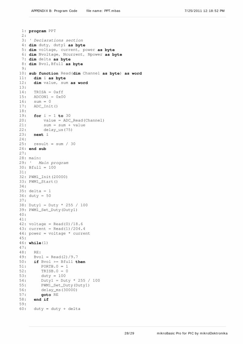
In other words, the MPPT will change the conversion ratio by a specific value, and see if the power increases or not. Accordingly it will continue changing with the same direction or reverse it. The program for this process is fixed in Appendix 2. It is written in MikroBasic programming language, and compiled with MikroBasic for PIC software. Other Circuit Partitions Other main hardware partitions of our design are the Status LED and the power supply voltage regulator: 1. Status LED:
The purpose of this LED is to give the user an indicator about the battery status that could be one of these three possibilities:
‐ Battery is fully charged → LED is continuously ON.
‐ Battery is charging now → LED is BLINKING.
‐ No enough power to charge → LED is OFF.

Internship Report – HS Bochum Solar Car Project (MPPT Design) ‐ Mahmood Shubbak 23/29
2. Power Supply Voltage Regulator: To operate the PIC microcontroller and the current sensing IC we need to supply them with a constant voltage of 5V. This is the function of the 78L05 Voltage regulator.

Internship Report – HS Bochum Solar Car Project (MPPT Design) ‐ Mahmood Shubbak 24/29
References:
[1] How Stuff Works website; http://science.howstuffworks.com/environmental /energy/solar‐cell1.htm
[2] Solar Energy International Photovoltaics: Design and Installation Manual, renewable energy education for a sustainable future , New Society Publishers, 2004, ISBN: 0865715203, 9780865715202.
[3] Jaycar Electronics (Reference Data Sheet: DCDCCONV.PDF) DC‐DC CONVERTERS: A PRIMER.
[4] Roberto Faranda, Sonia Leva Energy comparison of MPPT techniques for PV Systems, Issue 6, Volume 3, June 2008, ISSN: 1790‐5060.
[5] Tim Nolan Peak Power Tracker Project, (www.timnolan.com).
[6] Tim Nolan Peak Power Tracker Circuit Description V1.00 2/14/03, (www.timnolan.com).
[7] Microchip Technology Inc, AN1211 Maximum Power Solar Converter, DS01211B.
[8] Wikipedia.
[9] National Instruments LabView help library.
[10] Bo Hanus, Akkus und Batterien richtig pflegen und laden, FRANZIS, ISBN10: 3772343899.
[11] Microchip Technology Inc, PIC16F873 data sheet.
[12] mikroElektronika Inc, mikroBasic Pro for PIC Software Help Library.

Internship Report – HS Bochum Solar Car Project (MPPT Design) ‐ Mahmood Shubbak 25/29
APPENDICES
APPENDIX A: Circuit Schematic and Components List
On the next three pages, the circuit schematics of our MPPT design is fixed, followed by a components list.
APPENDIX B: Program Code
The source code of the MPPT microcontroller program is fixed on pages 28 and 29.
This program has been written in MikroBasic language.
It was compiled and tested with mikroBasic Pro for PIC Software by mikroElektronika Inc.

Power Supply Power Supply Voltage RegulatorVoltage Regulator
Current Current SensorSensor
Boost ConverterBoost ConverterFrom Solar From Solar
PanelPanelTo To
BatteryBattery
Solar Solar PanelPanel
Status LEDStatus LEDPanel Panel Voltage Voltage SensorSensor
Battery Battery Voltage Voltage SSSensorSensor
MicrocontrollerMicrocontroller
Debug Port Debug Port (to PICkit(to PICkit22))

2 7
U2:A
TC4427
C2470u
R41K
C70.1u
R21K
C60.1u
VCC1
RS+8
OUT 4
GND3
RS- 6
U4
MAX4372HESA
X1
CRYSTAL 20 MHzC922pF
C822pF
L1
7447709101100uH
VI3 VO 1
GN
D2
U378L05
C1470u
C50.1u
12
JI
TBLOCK-I2Solar Panel
12
JO
TBLOCK-I2Battery
R5.01Ohm
Current Sensing Resistor
D2
LED
R61.2K
RA0/AN02
RA1/AN13
RA2/AN2/VREF-4
RA4/T0CKI6
RA5/AN4/SS7
OSC1/CLKIN9
OSC2/CLKOUT10
RC1/T1OSI/CCP2 12
RC2/CCP1 13
RC3/SCK/SCL 14
RB7/PGD 28RB6/PGC 27RB5 26RB4 25RB3/PGM 24RB2 23RB1 22RB0/INT 21
RC7/RX/DT 18RC6/TX/CK 17RC5/SDO 16RC4/SDI/SDA 15
RA3/AN3/VREF+5
RC0/T1OSO/T1CKI 11
MCLR/Vpp/THV1
U1
PIC16F873
Q1IRF7468
R110K
R320K
12345
JP
CONN-SIL5To PICkit2.0
D1
10MQ100NR72.2K
R81.2K C3
0.33u
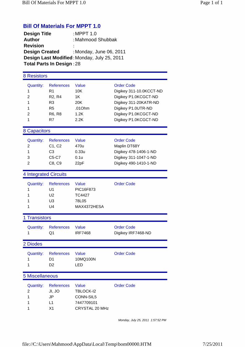
Bill Of Materials For MPPT 1.0 Design Title :MPPT 1.0Author :Mahmood ShubbakRevision :Design Created :Monday, June 06, 2011Design Last Modified :Monday, July 25, 2011Total Parts In Design :28
8 Resistors
Quantity: References Value Order Code1 R1 10K Digikey 311-10.0KCCT-ND2 R2, R4 1K Digikey P1.0KCGCT-ND1 R3 20K Digikey 311-20KATR-ND1 R5 .01Ohm Digikey P1.0UTR-ND2 R6, R8 1.2K Digikey P1.0KCGCT-ND1 R7 2.2K Digikey P1.0KCGCT-ND
8 Capacitors
Quantity: References Value Order Code2 C1, C2 470u Maplin DT68Y1 C3 0.33u Digikey 478-1406-1-ND3 C5-C7 0.1u Digikey 311-1047-1-ND2 C8, C9 22pF Digikey 490-1410-1-ND
4 Integrated Circuits
Quantity: References Value Order Code1 U1 PIC16F873 1 U2 TC4427 1 U3 78L05 1 U4 MAX4372HESA
1 Transistors
Quantity: References Value Order Code1 Q1 IRF7468 Digikey IRF7468-ND
2 Diodes
Quantity: References Value Order Code1 D1 10MQ100N 1 D2 LED
5 Miscellaneous
Quantity: References Value Order Code2 JI, JO TBLOCK-I2 1 JP CONN-SIL5 1 L1 7447709101 1 X1 CRYSTAL 20 MHz
Monday, July 25, 2011 1:57:52 PM
Page 1 of 1Bill Of Materials For MPPT 1.0
7/25/2011file://C:\Users\Mahmood\AppData\Local\Temp\bom00000.HTM
APPENDIX B: Program Code file name: PPT.mbas 7/25/2011 12:18:52 PM
1: program PPT2: 3: ' Declarations section 4: dim duty, duty1 as byte5: dim voltage, current, power as byte6: dim Nvoltage, Ncurrent, Npower as byte7: dim delta as byte8: dim Bvol,Bfull as byte9: 10: sub function Read(dim Channel as byte) as word11: dim i as byte12: dim value, sum as word13: 14: TRISA = 0xff15: ADCON1 = 0x0016: sum = 017: ADC_Init()18: 19: for i = 1 to 3020: value = ADC_Read(Channel)21: sum = sum + value22: delay_us(75)23: next i24: 25: result = sum / 3026: end sub27: 28: main:29: ' Main program 30: Bfull = 10031: 32: PWM1_Init(20000)33: PWM1_Start()34: 35: delta = 136: duty = 5037: 38: Duty1 = Duty * 255 / 10039: PWM1_Set_Duty(Duty1)40: 41: 42: voltage = Read(0)/18.643: current = Read(1)/204.444: power = voltage * current45: 46: while(1)47: 48: RE:49: Bvol = Read(2)/9.750: if Bvol >= Bfull then51: PORTB.0 = 152: TRISB.0 = 053: duty = 10054: Duty1 = Duty * 255 / 10055: PWM1_Set_Duty(Duty1)56: delay_ms(30000)57: goto RE58: end if59: 60: duty = duty + delta
28/29 mikroBasic Pro for PIC by mikroElektronika

PPT.mbas 7/25/2011 12:18:52 PM
61: If duty < 0 then62: duty = 063: end if64: If duty > 99 then65: duty = 9966: end if67: 68: Duty1 = Duty * 255 / 10069: PWM1_Set_Duty(Duty1)70: 71: Nvoltage = Read(0)/18.672: Ncurrent = Read(1)/204.473: Npower = Nvoltage * Ncurrent74: 75: If Npower < power then76: delta = -1 * delta77: end if78: 79: power = Npower80: 81: PORTB.0 = 182: delay_ms(100)83: PORTB.0 = 084: delay_ms(100)85: 86: wend87: 88: end.
29/29 mikroBasic Pro for PIC by mikroElektronika