may 2007 revised: april 2009 cvd grade for … no.005-usa may 2007 revised: april 2009...
TRANSCRIPT
T5100
No.005-USAMay 2007
Revised: April 2009
A new grade & chipbreaker series for all types of work and processing conditions
CVD Grade for Turning Cast Iron and Ductile Cast Iron

Feed (mm/rev)
Cutti
ngSp
eed
Vc(m/min)
■ Applicable Areas●T5115 - First ChoiceThis multi-purpose grade provides stableprocessing in a wide range of areas,from continuous to interrupted cutting.
●T5105 - High Wear ResistanceExhibits superior wear and plasticdeformation resistance in high speedcontinuous cutting.
●T5125 - High Impact ResistanceTough grade prevents sudden breakageand is suited for heavy interruptedcutting.
The fine grain and high carbonization coating of the T5100 SeriesT5100 Series greatly iand the 3 chipbreaker types yield excellent per
Enhanced chip welding resistance Smooth outermost coating layer
■ Comparison of coating surfaces
Conventional Type T5100
■ Comparison of chip welding resistanceThe smooth coating surface suppresses chip weldingimproving the work surface finish.
Conventional Type T5115
Insert: CNMG 433 CMGrade: T5115Work Material: FCD600Work Process: Continuous and
Interrupted CuttingCutting Speed: vc=500 SFMDepth of Cut: ap=.080"Feed: f=.014 IPRCoolant: Water Soluble
Comparison of chip weldingafter 40 minutes of processing
■ Standard Cutting Conditions
T5100
GradeCutting Speed vc m/min (inch)
ISO CodeSubstrate Coating Layers
Cast Iron Ductile Cast IronSpecificGravity
Hardness(HRA)
Tensile Strength(GPa)
Main Component Thickness
T5105 180 - 480 (600 - 1600) 180 - 400 (600 - 1300) K05-K15 15.0 92.5 2.4Fine columnar TiCN
+ AR2O3
16T5115 140 - 400 (450 - 1300) 140 - 370 (450 - 1200) K10-K20 14.8 91.5 2.7 16
T5125 120 - 300 (400 - 1000) 120 - 250 (400 - 820) K15-K30 14.0 90.5 2.8 16
1
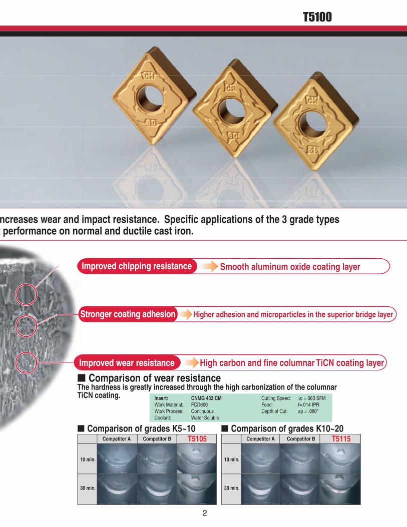
ncreases wear and impact resistance. Specific applications of the 3 grade typesa t performance on normal and ductile cast iron.
E Improved chipping resistance Smooth aluminum oxide coating layer
Stronger coating adhesion Higher adhesion and microparticles in the superior bridge layer
Improved wear resistance High carbon and fine columnar TiCN coating layer
■ Comparison of wear resistanceThe hardness is greatly increased through the high carbonization of the columnarTiCN coating.
■ Comparison of grades K5~10 ■ Comparison of grades K10~20
Insert: CNMG 433 CMWork Material: FCD600Work Process: ContinuousCoolant: Water Soluble
Cutting Speed: vc = 660 SFMFeed: f=.014 IPRDepth of Cut: ap = .080"
Competitor A Competitor B T5105
10 min.
30 min.
Competitor A Competitor B T5115
10 min.
30 min.
2
T5100

3
T5100
CMChipbreaker CFeed
Dept
hof
Cut
First Choice
Close fitting seatThe relief surface extends optimally close to the end of the cuttingedge while avoiding direct impact from the chips. Stabilizes inserttool life by supressing vibration when cutting.
Positive landThe excellent cutting edge shape offers a balance of low resistanceand breakage resistance. Applicable for a wide range of processesfrom continuous to interrupted cutting.
Long tool life in continuous and interrupted cutting.The CM type chipbreaker shows itssuperiority in processes that combine continuousand interrupted cutting.
All-Around Chipbreaker
Insert: CNMG 433 CMGrade: T5115Toolholder: ACLNR2525M12Work Material: FCD600
Continuous andInterrupted Cutting
Cutting Speed: vc=500 SFMDepth of Cut: ap=.080"Feed: f=.014 IPRCoolant: Water Soluble
Burr preventive effect.The optimal edge control of the CM chipbreakerprevents burr and edge breakout. Moreover, incombination with the T5100 series, consistencyimproves.
Insert: CNMG 433 CMGrade: T5115Toolholder: ACLNR2525M12Work Material: FCD600
Continuous andInterrupted Cutting
Cutting Speed: vc =500 SFMDepth of Cut: ap=.080"Feed: f=.014 IPRCoolant: Water Soluble
Max
flank
wea
rwid
thVB
max
(in) .020
.016
.012
.008
.004
010 20 30 40 50 60 70
Net Cutting Time T (min.)
Comp. ATungaloyConventional Product(K20)
T5115 CM Type
T5115 CM TypeTungaloy ConventionalProduct
Competitor A
Competitors all purpose type insertafter 20 minutes
●Burr height difference■ Competitors all purpose type■ T5115 type
Burr
heig
ht(in
)
.047
.040
.031
.024
.016
.008
05 10 15 20 25
Net Cutting Time T (min.)
.017 in.
.043 in.
T5115 CM typeafter 20 minutes
Big wear Breakage Small wear
WithstandsInterrupted Cutting
35 min.
40 min.
60 min.
4
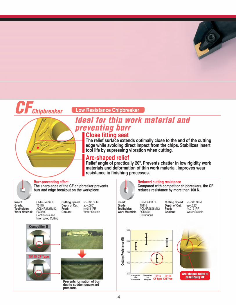
CFChipbreaker Low Resistance Chipbreaker
Close fitting seatThe relief surface extends optimally close to the end of the cuttingedge while avoiding direct impact from the chips. Stabilizes inserttool life by supressing vibration when cutting.
Arc-shaped reliefRelief angle of practically 20º. Prevents chatter in low rigidity workmaterials and deformation of thin work material. Improves wearresistance in finishing processes.
Ideal for thin work material andpreventing burr
Burr-preventing effectThe sharp edge of the CF chipbreaker preventsburr and edge breakout on the workpiece
Insert: CNMG 433 CFGrade: T5115Toolholder: ACLNR2525M12Work Material: FCD600
Continuous andInterrupted Cutting
Reduced cutting resistanceCompared with competitor chipbreakers, the CFreduces resistance by more than 100 N.
Cutting Speed: vc=500 SFMDepth of Cut: ap=.080"Feed: f=.014 IPRCoolant: Water Soluble
Insert: CNMG 433 CFGrade: T5115Toolholder: ACLNR2525M12Work Material: FCD600
Continuous
Cutting Speed: vc=660 SFMDepth of Cut: ap=.020"Feed: f=.012 IPRCoolant: Water Soluble
T5115 CF Type
Competitor B
Prevents formation of burrdue to sudden downwardpressure.
1600
1500
1400
1300
1200
Cutti
ngRe
sist
ance
(N)
CompetitorLow
Resistance
CompetitorAll
Purpose
T5115CF Type
T5115CM Type
Arc-shaped relief ofArc-shaped relief ofpractically 20ºpractically 20º
5
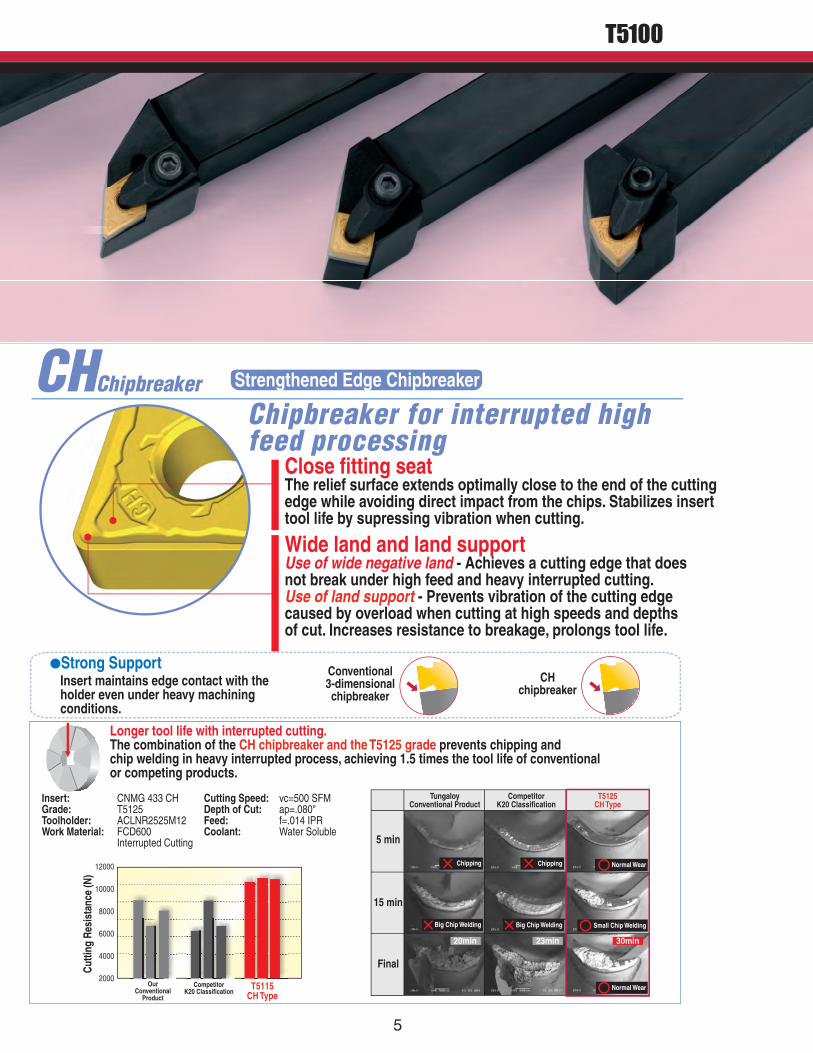
T5100
CHChipbreaker Strengthened Edge Chipbreaker
Close fitting seatThe relief surface extends optimally close to the end of the cuttingedge while avoiding direct impact from the chips. Stabilizes inserttool life by supressing vibration when cutting.
Wide land and land supportUse of wide negative land - Achieves a cutting edge that doesnot break under high feed and heavy interrupted cutting.Use of land support - Prevents vibration of the cutting edgecaused by overload when cutting at high speeds and depthsof cut. Increases resistance to breakage, prolongs tool life.
Chipbreaker for interrupted highfeed processing
Longer tool life with interrupted cutting.The combination of the CH chipbreaker and the T5125 grade prevents chipping andchip welding in heavy interrupted process, achieving 1.5 times the tool life of conventionalor competing products.
Insert: CNMG 433 CHGrade: T5125Toolholder: ACLNR2525M12Work Material: FCD600
Interrupted Cutting
Cutting Speed: vc=500 SFMDepth of Cut: ap=.080"Feed: f=.014 IPRCoolant: Water Soluble
●Strong SupportInsert maintains edge contact with theholder even under heavy machiningconditions.
Conventional3-dimensionalchipbreaker
CHchipbreaker
OurConventional
Product
CompetitorK20 Classification
T5115CH Type
Cutti
ngRe
sist
ance
(N)
12000
10000
8000
6000
4000
2000
20min 23min 30min
Chipping
Big Chip Welding
Chipping
Big Chip Welding
Normal Wear
Small Chip Welding
Chipping
Normal Wear
TungaloyConventional Product
CompetitorK20 Classification
T5125CH Type
5 min
15 min
Final
3
6
T5100
CH Chipbreaker
CM Chipbreaker
CF Chipbreaker
T5
125
T5
12
5
T5
115
T5
11
5
T5
105
T5
10
5
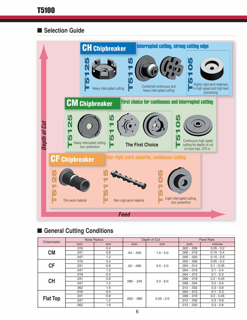
Interrupted cutting, strong cutting edge
First choice for continuous and interrupted cutting
Non-rigid work material, continuous cutting
Heavy interrupted cutting Combined continuous andheavy interrupted cutting
Highly rigid work materialsin high speed and high feed
processing
T5
125
T5
12
5
T5
115
T5
11
5
T5
105
T5
10
5
Heavy interrupted cutting,burr prevention The First Choice
Continuous high speedcutting for depths of cutof more than .079 in.
T5
125
T5
12
5
T5
115
T5
11
5
T5
105
T5
10
5
Thin work material Non-rigid work material Light interrupted cutting,burr prevention
Feed
Dep
thof
Cut
ChipbreakerNose Radius Depth of Cut Feed Rate
inch mm inch mm inch mm/rev
CM.016 0.4
.04 - .200 1.0 - 5.0.002 - .008 0.05 - 0.2
.031 0.8 .006 - .016 0.15 - 0.4
.047 1.2 .006 - .020 0.15 - 0.5
CF.016 0.4
.02 - .080 0.5 - 2.0.002 - .008 0.05 - 0.2
.031 0.8 .004 - .014 0.1 - 0.35
.047 1.2 .004 - .016 0.1 - 0.4
CH.016 0.4
.080 - .240 2.0 - 6.0
.004 - .012 0.1 - 0.3.031 0.8 .008 - .018 0.2 - 0.45.047 1.2 .008 - .024 0.2 - 0.6.062 1.6 .012 - .032 0.3 - 0.8
Flat Top.016 0.4
.002 - .080 0.05 - 2.0
.004 - .012 0.1 - 0.3.031 0.8 .008 - .018 0.2 - 0.45.047 1.2 .012 - .032 0.3 - 0.8.062 1.6 .012 - .032 0.3 - 0.8
� Selection Guide
� General Cutting Conditions
7
Finishing
CFCF ChipbreakerChipbreaker
f (in/rev)0 .008 .016 .024 .032 .040
.400
.320
.240
.160
.080D
OC
(in)
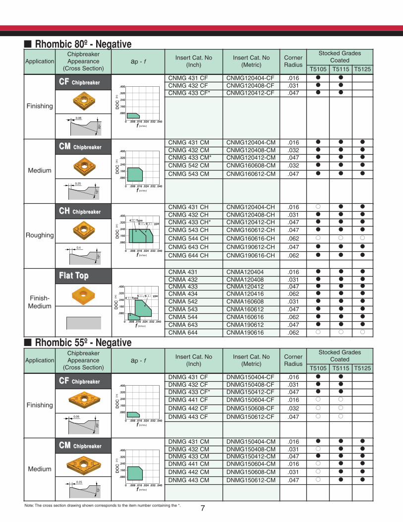
CNMG 431 CF CNMG120404-CF .016 � �
CNMG 432 CF CNMG120408-CF .031 � �
CNMG 433 CF* CNMG120412-CF .047 � �
0.06
20º
ApplicationChipbreakerAppearance(Cross Section)
ap - fInsert Cat. No
(Inch)Insert Cat. No(Metric)
CornerRadius
Stocked GradesCoated
T5105 T5115 T5125
� Rhombic 80º - Negative
Medium
CMCM ChipbreakerChipbreaker
f (in/rev)0 .008 .016 .024 .032 .040
.400
.320
.240
.160
.080
DO
C(in
)
CNMG 431 CM CNMG120404-CM .016 � � �
CNMG 432 CM CNMG120408-CM .032 � � �
CNMG 433 CM* CNMG120412-CM .047 � � �
CNMG 542 CM CNMG160608-CM .032 � � �
CNMG 543 CM CNMG160612-CM .047 � � �
0.25
15º
Roughing
CHCH ChipbreakerChipbreaker
f (in/rev)0 .008 .016 .024 .032 .040
.400
.320
.240
.160
.080
DO
C(in
)
4■■ Type5■■, 6■■
T
ype
CNMG 431 CH CNMG120404-CH .016 �� � �
CNMG 432 CH CNMG120408-CH .031 � � �
CNMG 433 CH* CNMG120412-CH .047 � � �
CNMG 543 CH CNMG160612-CH .047 � � �
CNMG 544 CH CNMG160616-CH .062 �� �� ��
0.4
15º
CNMG 643 CH CNMG190612-CH .047 � � �
CNMG 644 CH CNMG190616-CH .062 � � �
Finish-Medium
Flat TopFlat Top
f (in/rev)0 .008 .016 .024 .032 .040
.400
.320
.240
.160
.080
DO
C (i
n) 4■■ Type5■■, 6■■
T
ype
CNMA 431 CNMA120404 .016 � � �
CNMA 432 CNMA120408 .031 � � �
CNMA 433 CNMA120412 .047 � � �
CNMA 434 CNMA120416 .062 � � �
CNMA 542 CNMA160608 .031 � � �
CNMA 543 CNMA160612 .047 � � �
CNMA 544 CNMA160616 .062 � � �
CNMA 643 CNMA190612 .047 � � �
CNMA 644 CNMA190616 .062 �� �� ��
Finishing
CF CF ChipbreakerChipbreaker
f (in/rev)0 .008 .016 .024 .032 .040
.400
.320
.240
.160
.080
DO
C (i
n)
DNMG 431 CF DNMG150404-CF .016 � �
DNMG 432 CF DNMG150408-CF .031 � �
DNMG 433 CF* DNMG150412-CF .047 � �
DNMG 441 CF DNMG150604-CF .016 �� ��
DNMG 442 CF DNMG150608-CF .032 �� ��
0.06
20º
DNMG 443 CF DNMG150612-CF .047 �� ��
ApplicationChipbreakerAppearance(Cross Section)
ap - f Insert Cat. No (Inch)
Insert Cat. No (Metric)
CornerRadius
Stocked GradesCoated
T5105 T5115 T5125
� Rhombic 55º - Negative
Medium
CM CM ChipbreakerChipbreaker
f (in/rev)0 .008 .016 .024 .032 .040
.400
.320
.240
.160
.080
DO
C (i
n)
DNMG 431 CM DNMG150404-CM .016 � � �
DNMG 432 CM DNMG150408-CM .031 �� � �
DNMG 433 CM DNMG150412-CM .047 � � �
DNMG 441 CM DNMG150604-CM .016 �� � �
DNMG 442 CM DNMG150608-CM .031 �� � �
0.25
15º
DNMG 443 CM DNMG150612-CM .047 �� � �
Note: The cross section drawing shown corresponds to the item number containing the *.

87
T5100
Finishing
CF CF ChipbreakerChipbreaker
f (in/rev)0 .008 .016 .024 .032 .040
.400
.320
.240
.160
.080
DO
C (i
n)
SNMG 432 CF SNMG120408-CF .031 � �
SNMG 433 CF* SNMG120412-CF .047 � �
0.06
20º
ApplicationChipbreakerAppearance(Cross Section)
ap - f Insert Cat. No (Inch)
Insert Cat. No (Metric)
CornerRadius
Stocked GradesCoated
T5105 T5115 T5125
� Square 90º - Negative
Finishing
CM CM ChipbreakerChipbreaker
f (in/rev)0 .008 .016 .024 .032 .040
.400
.320
.240
.160
.080
DO
C (i
n)
SNMG 432 CM SNMG120408-CM .031 � � �
SNMG 433 CM* SNMG120412-CM .047 � � �
0.25
15º
Roughing
CH CH ChipbreakerChipbreaker
f (in/rev)0 .008 .016 .024 .032 .040
.400
.320
.240
.160
.080
DO
C (i
n)
SNMG 432 CH SNMG120408-CH .031 � � �
SNMG 433 CH* SNMG120412-CH .047 � � �
SNMG 434 CH SNMG120416-CH .062 � � �
0.4
15º
Finish-Medium
Flat TopFlat Top
f (in/rev)0 .008 .016 .024 .032 .040
.400
.320
.240
.160
.080
DO
C (i
n)
SNMA 322 SNMA090308 .031 � � �
SNMA 323 SNMA090312 .047 � � �
SNMA 431 SNMA120404 .016 � � �
SNMA 432 SNMA120408 .031 � � �
SNMA 433 SNMA120412 .047 � � �
SNMA 434 SNMA120416 .062 � � �
SNMA 543 SNMA150612 .047 � � �
SNMA 643 SNMA190612 .047 � � �
Roughing
CH CH ChipbreakerChipbreaker
f (in/rev)0 .008 .016 .024 .032 .040
.400
.320
.240
.160
.080
DO
C (i
n)
DNMG 431 CH DNMG150404-CH .016 �� � �
DNMG 432 CH DNMG150408-CH .031 � � �
DNMG 433 CH* DNMG150412-CH .047 � � �
DNMG 441 CH DNMG150604-CH .016 �� � �
DNMG 442 CH DNMG150608-CH .031 �� � �
0.4
15º
DNMG 443 CH DNMG150612-CH .047 � �� �
ApplicationChipbreakerAppearance(Cross Section)
ap - f Insert Cat. No (Inch)
Insert Cat. No (Metric)
CornerRadius
Stocked GradesCoated
T5105 T5115 T5125
Finish -Medium
Flat TopFlat Top
f (in/rev)0 .008 .016 .024 .032 .040
.400
.320
.240
.160
.080
DO
C (i
n)
DNMA 431 DNMA150404 .016 � � �
DNMA 432 DNMA150408 .031 � � �
DNMA 433 DNMA150412 .047 � � �
DNMA 441 DNMA150604 .016 �� � �
DNMA 442 DNMA150608 .032 �� � �
DNMA 443 DNMA150612 .047 � �� ��
Note: The cross section drawing shown corresponds to the item number containing the *.
9
T5100
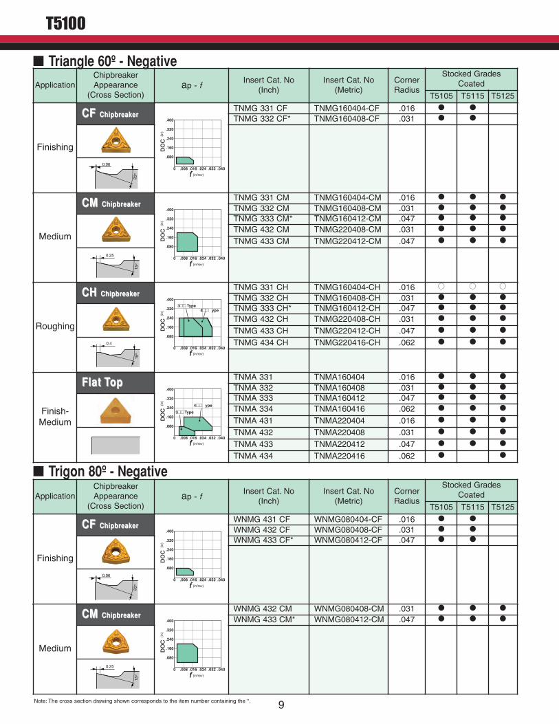
Finishing
CF CF ChipbreakerChipbreaker
f (in/rev)0 .008 .016 .024 .032 .040
.400
.320
.240
.160
.080D
OC
(in)
TNMG 331 CF TNMG160404-CF .016 � �
TNMG 332 CF* TNMG160408-CF .031 � �
0.06
20º
ApplicationChipbreakerAppearance(Cross Section)
ap - f Insert Cat. No (Inch)
Insert Cat. No (Metric)
CornerRadius
Stocked GradesCoated
T5105 T5115 T5125
� Triangle 60º - Negative
Medium
CM CM ChipbreakerChipbreaker
f (in/rev)0 .008 .016 .024 .032 .040
.400
.320
.240
.160
.080
DO
C (i
n)
TNMG 331 CM TNMG160404-CM .016 � � �
TNMG 332 CM TNMG160408-CM .031 � � �
TNMG 333 CM* TNMG160412-CM .047 � � �
TNMG 432 CM TNMG220408-CM .031 � � �
TNMG 433 CM TNMG220412-CM .047 � � �
0.25
15º
Roughing
CH CH ChipbreakerChipbreaker
f (in/rev)0 .008 .016 .024 .032 .040
.400
.320
.240
.160
.080
DO
C (i
n)
3■■ Type4■■
T
ype
TNMG 331 CH TNMG160404-CH .016 �� �� ��
TNMG 332 CH TNMG160408-CH .031 � � �
TNMG 333 CH* TNMG160412-CH .047 � � �
TNMG 432 CH TNMG220408-CH .031 � � �
TNMG 433 CH TNMG220412-CH .047 � � �
0.4
15º
TNMG 434 CH TNMG220416-CH .062 � � �
Finish-Medium
Flat TopFlat Top
f (in/rev)0 .008 .016 .024 .032 .040
.400
.320
.240
.160
.080
DO
C (i
n)
3■■ Type4■■
T
ype
TNMA 331 TNMA160404 .016 � � �
TNMA 332 TNMA160408 .031 � � �
TNMA 333 TNMA160412 .047 � � �
TNMA 334 TNMA160416 .062 � � �
TNMA 431 TNMA220404 .016 � � �
TNMA 432 TNMA220408 .031 � � �
TNMA 433 TNMA220412 .047 � � �
TNMA 434 TNMA220416 .062 � �
Finishing
CF CF ChipbreakerChipbreaker
f (in/rev)0 .008 .016 .024 .032 .040
.400
.320
.240
.160
.080
DO
C (i
n)
WNMG 431 CF WNMG080404-CF .016 � �
WNMG 432 CF WNMG080408-CF .031 � �
WNMG 433 CF* WNMG080412-CF .047 � �
0.06
20º
ApplicationChipbreakerAppearance(Cross Section)
ap - f Insert Cat. No (Inch)
Insert Cat. No (Metric)
CornerRadius
Stocked GradesCoated
T5105 T5115 T5125
� Trigon 80º - Negative
Medium
CM CM ChipbreakerChipbreaker
f (in/rev)0 .008 .016 .024 .032 .040
.400
.320
.240
.160
.080
DO
C (i
n)
WNMG 432 CM WNMG080408-CM .031 � � �
WNMG 433 CM* WNMG080412-CM .047 � � �
0.25
15º
Note: The cross section drawing shown corresponds to the item number containing the *.
9 10
T5100
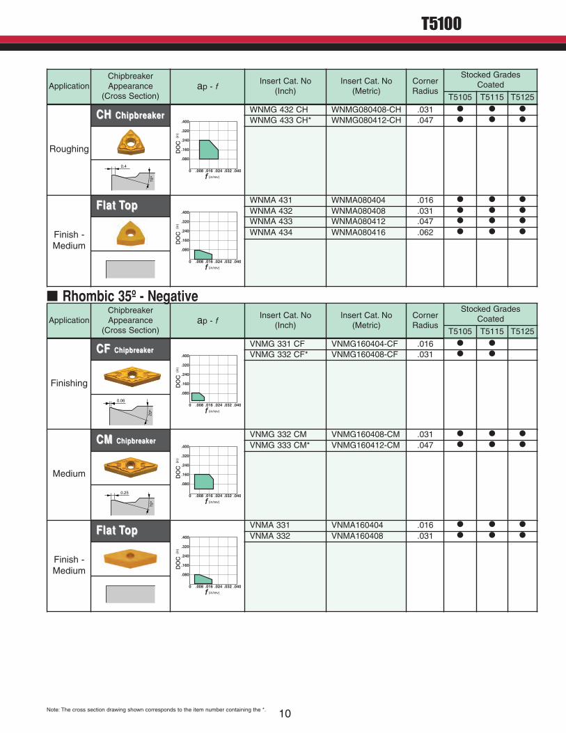
Finishing
CF CF ChipbreakerChipbreaker
f (in/rev)0 .008 .016 .024 .032 .040
.400
.320
.240
.160
.080
DO
C (i
n)
VNMG 331 CF VNMG160404-CF .016 � �
VNMG 332 CF* VNMG160408-CF .031 � �
0.06
20º
ApplicationChipbreakerAppearance(Cross Section)
ap - f Insert Cat. No (Inch)
Insert Cat. No (Metric)
CornerRadius
Stocked GradesCoated
T5105 T5115 T5125
� Rhombic 35º - Negative
Medium
CM CM ChipbreakerChipbreaker
f (in/rev)0 .008 .016 .024 .032 .040
.400
.320
.240
.160
.080
DO
C (i
n)
VNMG 332 CM VNMG160408-CM .031 � � �
VNMG 333 CM* VNMG160412-CM .047 � � �
0.25
15º
Finish -Medium
Flat TopFlat Top
f (in/rev)0 .008 .016 .024 .032 .040
.400
.320
.240
.160
.080
DO
C (i
n)
VNMA 331 VNMA160404 .016 � � �
VNMA 332 VNMA160408 .031 � � �
Roughing
CH CH ChipbreakerChipbreaker
f (in/rev)0 .008 .016 .024 .032 .040
.400
.320
.240
.160
.080
DO
C (i
n)
WNMG 432 CH WNMG080408-CH .031 � � �
WNMG 433 CH* WNMG080412-CH .047 � � �
0.4
15º
ApplicationChipbreakerAppearance(Cross Section)
ap - f Insert Cat. No (Inch)
Insert Cat. No (Metric)
CornerRadius
Stocked GradesCoated
T5105 T5115 T5125
Finish -Medium
Flat TopFlat Top
f (in/rev)0 .008 .016 .024 .032 .040
.400
.320
.240
.160
.080
DO
C (i
n)
WNMA 431 WNMA080404 .016 � � �
WNMA 432 WNMA080408 .031 � � �
WNMA 433 WNMA080412 .047 � � �
WNMA 434 WNMA080416 .062 � � �
Note: The cross section drawing shown corresponds to the item number containing the *.
11
T5100
� Practical Examples
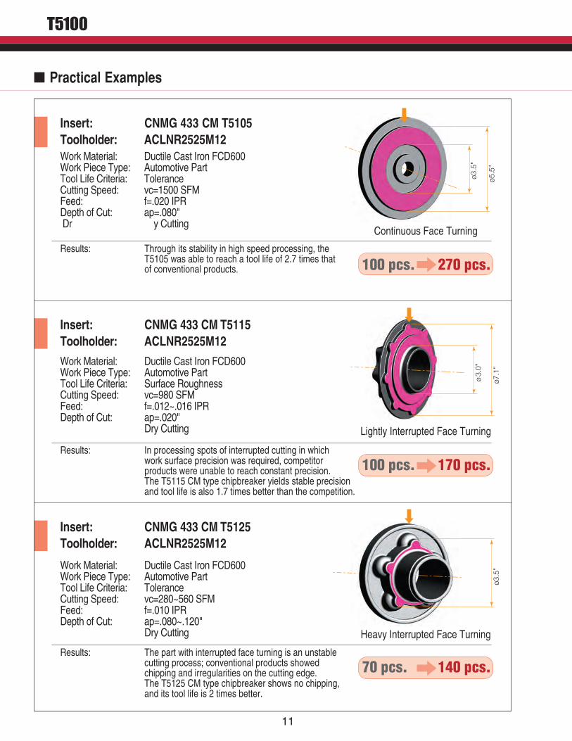
Insert: CNMG 433 CM T5105Toolholder: ACLNR2525M12Work Material: Ductile Cast Iron FCD600Work Piece Type: Automotive PartTool Life Criteria: ToleranceCutting Speed: vc=1500 SFMFeed: f=.020 IPRDepth of Cut: ap=.080" Dr y Cutting
Work Material: Ductile Cast Iron FCD600Work Piece Type: Automotive PartTool Life Criteria: Surface RoughnessCutting Speed: vc=980 SFMFeed: f=.012~.016 IPRDepth of Cut: ap=.020" Dry Cutting
Work Material: Ductile Cast Iron FCD600Work Piece Type: Automotive PartTool Life Criteria: ToleranceCutting Speed: vc=280~560 SFMFeed: f=.010 IPRDepth of Cut: ap=.080~.120" Dry Cutting
Insert: CNMG 433 CM T5115Toolholder: ACLNR2525M12
Insert: CNMG 433 CM T5125
Results: Through its stability in high speed processing, the T5105 was able to reach a tool life of 2.7 times that of conventional products.
Results: In processing spots of interrupted cutting in which work surface precision was required, competitor products were unable to reach constant precision. The T5115 CM type chipbreaker yields stable precision and tool life is also 1.7 times better than the competition.
Results: The part with interrupted face turning is an unstable cutting process; conventional products showed chipping and irregularities on the cutting edge. The T5125 CM type chipbreaker shows no chipping, and its tool life is 2 times better.
Toolholder: ACLNR2525M12
ø5.5
"
ø3.5
"
ø7.1
"
ø3.
0"
ø3.5
"
Continuous Face Turning
Lightly Interrupted Face Turning
Heavy Interrupted Face Turning
100 pcs. 270 pcs.
100 pcs. 170 pcs.
70 pcs. 140 pcs.
11 12
T5100
ø2.4
"
ø1.2
"ø7
.1"
ø5.
9"
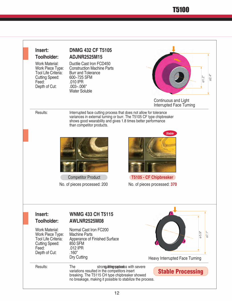
Insert: DNMG 432 CF T5105Toolholder: ADJNR2525M15Work Material: Ductile Cast Iron FCD450Work Piece Type: Construction Machine PartsTool Life Criteria: Burr and ToleranceCutting Speed: 600~725 SFMFeed: .010 IPRDepth of Cut: .003~.006" Water Soluble
Work Material: Normal Cast Iron FC200Work Piece Type: Machine PartsTool Life Criteria: Apperance of Finished SurfaceCutting Speed: 850 SFMFeed: .012 IPRDepth of Cut: .160" Dry Cutting
Insert: WNMG 433 CH T5115
Results: Interrupted face cutting process that does not allow for tolerance variances in external turning or burr. The T5105 CF type chipbreaker shows good wearability and gives 1.8 times better performance than competitor products.
Results: The strong interrupted cutting process with severe variations resulted in the competitors insert breaking. The T5115 CH type chipbreaker showed no breakage, making it possible to stabilize the process.
Toolholder: AWLNR2525M08
Continuous and LightInterrupted Face Turning
No. of pieces processed: 200 No. of pieces processed: 370
Heavy Interrupted Face Turning
Stable Processing
Competitor Product T5105 - CF Chipbreaker
Stable
1226A Michael Drive, Wood Dale, IL 60191Customer Service: 1-888-554-8394Technical Support: 1-888-554-8391Fax: 1-888-554-8392
Tungaloy Canada432 Elgin Street, Unit 3, Brantford, Ontario, Canada N3S-7P7Toll Free: 888-886-4256, Phone: 519-758-5779, Fax: 519-758-5791
Tungaloy de Mexico S.A.C Los Arellano 113, Vista Alegre, Aguascalientes, AGS, Mexico 20290Phone: 011-52-449-929-5410, Fax: 011-52-449-929-5411
Distributed By:
www.tungaloyamerica.com