cvd coated grade for steel turning mc6115
TRANSCRIPT
TOOL NEWS
MC6115 NEW
B266B
CVD Coated Grade for Steel Turning
Bringing the Ultimate Performance in High Speed Cutting
1
MC6115CVD Coated Grade for Steel Turning
Features
*By Image
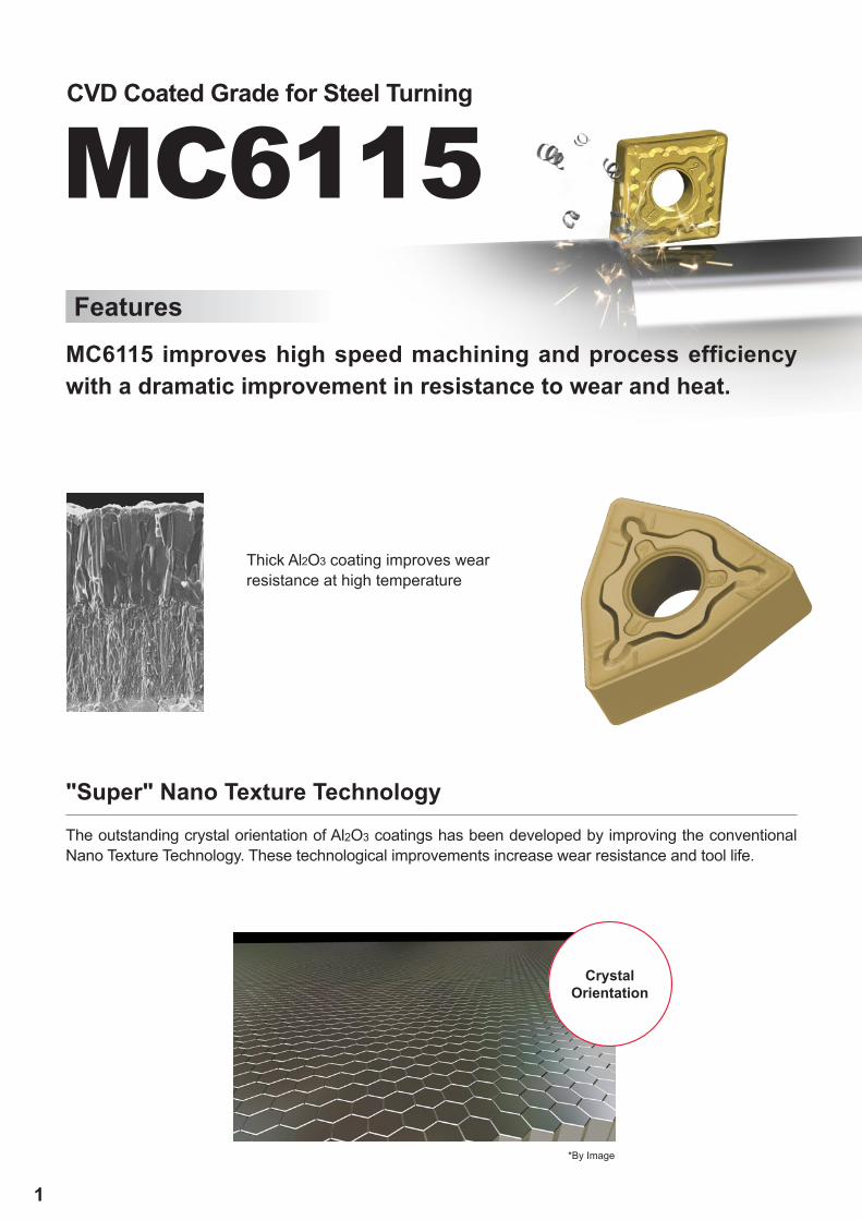
Crystal Orientation
MC6115 improves high speed machining and process efficiency with a dramatic improvement in resistance to wear and heat.
"Super" Nano Texture TechnologyThe outstanding crystal orientation of Al2O3 coatings has been developed by improving the conventional Nano Texture Technology. These technological improvements increase wear resistance and tool life.
Thick Al2O3 coating improves wear resistance at high temperature
2
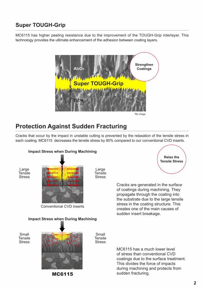
Al2O3
TiCN
MC6115
Super TOUGH-Grip
*By Image
Super TOUGH-Grip
Strengthen Coatings
Relax the Tensile Stress
Cracks that occur by the impact in unstable cutting is prevented by the relaxation of the tensile stress in each coating. MC6115 decreases the tensile stress by 80% compared to our conventional CVD inserts.
Protection Against Sudden Fracturing
Large Tensile Stress
Large Tensile Stress
Small Tensile Stress
Small Tensile Stress
Impact Stress when During Machining
Impact Stress when During Machining
Conventional CVD inserts
Cracks are generated in the surface of coatings during machining. They propagate through the coating into the substrate due to the large tensile stress in the coating structure. This creates one of the main causes of sudden insert breakage.
MC6115 has a much lower level of stress than conventional CVD coatings due to the surface treatment. This divides the force of impacts during machining and protects from sudden fracturing.
MC6115 has higher peeling resistance due to the improvement of the TOUGH-Grip interlayer. This technology provides the ultimate enhancement of the adhesion between coating layers.
3
ISO CVD
P
10
20
30
40
MC
6035
MC
6025M
C61
15
MC
6015
UE
6110
PMC6115
MC6025
MC6035
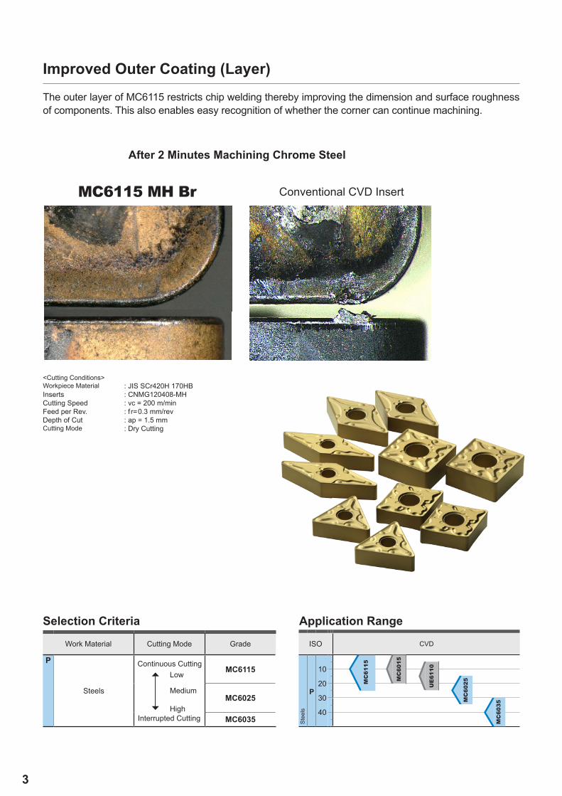
MC6115 MH Br
Selection Criteria Application Range
Work Material Cutting Mode Grade
Steels
Stee
ls
After 2 Minutes Machining Chrome Steel
Conventional CVD Insert
<Cutting Conditions> Workpiece Material : JIS SCr420H 170HB Inserts : CNMG120408-MHCutting Speed : vc = 200 m/minFeed per Rev. : f r=0.3 mm/revDepth of Cut : ap = 1.5 mmCutting Mode : Dry Cutting
Continuous Cutting
Interrupted Cutting
Low
Medium
High
Improved Outer Coating (Layer)The outer layer of MC6115 restricts chip welding thereby improving the dimension and surface roughness of components. This also enables easy recognition of whether the corner can continue machining.
4
M
LP 43210 0.1 0.3 0.5
11°0.2 mm
15°0.1 mm
SH 43210 0.1 0.3 0.5
15°
15° 0.2 mm
SA 43210 0.1 0.3 0.5
25°
25°8°
10°0.3 mm
0.34 mm
SW 43210 0.1 0.3 0.5
18°
18°7°
7°0.15 mm
0.15 mm
M
MP 543210 0.1 0.3 0.5
15°
11°
0.15 mm
0.2 mm
MA 543210 0.1 0.3 0.5
6°
6°
22°
22°
0.2 mm
0.2 mm
MH 543210 0.1 0.3 0.5
16°
16°
0.25 mm
0.35 mm
543210 0.1 0.3 0.5
15°
15°
0.25 mm
0.25 mm
MW 543210 0.1 0.3 0.5
19°
19°
0.25 mm
0.3 mm
CNMG120408-LP
CNMG120408-SH
CNMG120408-MP
CNMG120408-SA
CNMG120408-SW
CNMG120408-MH
CNMG120408
CNMG120408-MW
CNMG120408-MA
Appli
catio
n
Tole
ranc
e
Chip Breaker Name and
PictureFeatures Cross Section
Geometry
Ligh
t Cut
ting
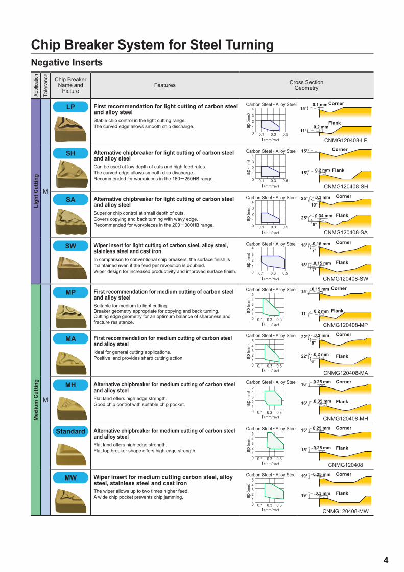
First recommendation for light cutting of carbon steel and alloy steelStable chip control in the light cutting range.The curved edge allows smooth chip discharge.
Alternative chipbreaker for light cutting of carbon steel and alloy steelCan be used at low depth of cuts and high feed rates.The curved edge allows smooth chip discharge.Recommended for workpieces in the 160─250HB range.
Alternative chipbreaker for light cutting of carbon steel and alloy steelSuperior chip control at small depth of cuts.Covers copying and back turning with wavy edge.Recommended for workpieces in the 200─300HB range.
Wiper insert for light cutting of carbon steel, alloy steel, stainless steel and cast ironIn comparison to conventional chip breakers, the surface finish is maintained even if the feed per revolution is doubled.Wiper design for increased productivity and improved surface finish.
Med
ium
Cut
ting
First recommendation for medium cutting of carbon steel and alloy steelSuitable for medium to light cutting.Breaker geometry appropriate for copying and back turning.Cutting edge geometry for an optimum balance of sharpness and fracture resistance.
First recommendation for medium cutting of carbon steel and alloy steelIdeal for general cutting applications.Positive land provides sharp cutting action.
Alternative chipbreaker for medium cutting of carbon steel and alloy steelFlat land offers high edge strength.Good chip control with suitable chip pocket.
Standard Alternative chipbreaker for medium cutting of carbon steel and alloy steelFlat land offers high edge strength.Flat top breaker shape offers high edge strength.
Wiper insert for medium cutting carbon steel, alloy steel, stainless steel and cast ironThe wiper allows up to two times higher feed.A wide chip pocket prevents chip jamming.
Carbon Steel • Alloy Steel
ap ( m
m)
f (mm/rev)
Corner
Flank
Carbon Steel • Alloy Steel
ap ( m
m)
f (mm/rev)
Corner
Flank
Carbon Steel • Alloy Steel
ap ( m
m)
f (mm/rev)
Corner
Flank
Carbon Steel • Alloy Steelap
( mm
)
f (mm/rev)
Corner
Flank
Carbon Steel • Alloy Steel
ap ( m
m)
f (mm/rev)
Corner
Flank
Carbon Steel • Alloy Steel
ap ( m
m)
f (mm/rev)
Corner
Flank
Carbon Steel • Alloy Steel
ap ( m
m)
f (mm/rev)
Corner
Flank
Carbon Steel • Alloy Steel
ap ( m
m)
f (mm/rev)
Corner
Flank
Carbon Steel • Alloy Steel
ap ( m
m)
f (mm/rev)
Corner
Flank
Chip Breaker System for Steel TurningNegative Inserts
5
M
RP 7
5
3
10 0.1 0.3 0.5 0.7
0.33 mm
3°0.33 mm
GH 7
5
3
10 0.1 0.3 0.5 0.7
18° 0.32 mm
0.32 mm18°
CNMG120408-GH
CNMG120408-RP
P
180─280HB
L MC6115 LP 250─480 0.10─0.40 0.30─2.00
L MC6115 SH 250─480 0.10─0.40 0.30─2.00
L MC6115 SA 250─480 0.10─0.40 0.30─2.00
L MC6115 SW 250─480 0.10─0.50 0.30─2.50
M MC6115 MP 230─440 0.16─0.50 0.30─4.00
M MC6115 MA 230─440 0.20─0.50 0.30─4.00
M MC6115 Std 230─440 0.25─0.60 1.50─5.00
M MC6115 MW 230─440 0.20─0.60 0.90─4.00
R MC6115 RP 215─415 0.25─0.60 1.50─6.00
R MC6115 GH 215─415 0.25─0.60 1.50─6.00
L MC6115 LP 250─480 0.10─0.40 0.30─2.00
L MC6115 SH 250─480 0.10─0.40 0.30─2.00
L MC6115 SA 250─480 0.10─0.40 0.30─2.00
L MC6115 SW 250─480 0.10─0.50 0.30─2.50
M MC6115 MP 230─440 0.16─0.50 0.30─4.00
M MC6115 MA 230─440 0.20─0.50 0.30─4.00
M MC6115 MH 230─440 0.20─0.55 1.00─4.00
M MC6115 Std 230─440 0.25─0.60 1.50─5.00
M MC6115 MW 230─440 0.20─0.60 0.90─4.00
R MC6115 RP 215─415 0.25─0.60 1.50─6.00
R MC6115 GH 215─415 0.25─0.60 1.50─6.00
(mm)
CVD Coated Grade for Steel Turning
Appli
catio
n
Tole
ranc
e
Chip Breaker Name and
PictureFeatures Cross Section
Geometry
Rou
gh C
uttin
g
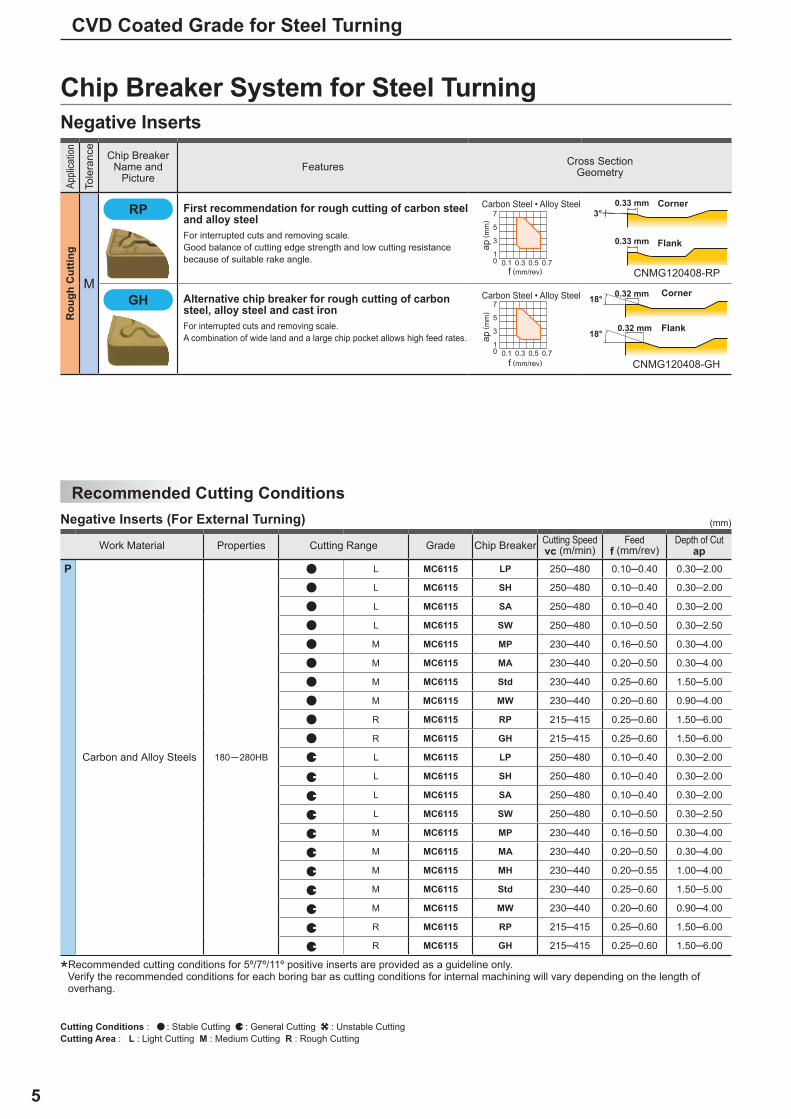
First recommendation for rough cutting of carbon steel and alloy steelFor interrupted cuts and removing scale.Good balance of cutting edge strength and low cutting resistance because of suitable rake angle.
Alternative chip breaker for rough cutting of carbon steel, alloy steel and cast ironFor interrupted cuts and removing scale.A combination of wide land and a large chip pocket allows high feed rates.
Carbon Steel • Alloy Steel
ap ( m
m)
f (mm/rev)
Corner
Flank
Carbon Steel • Alloy Steel
ap ( m
m)
f (mm/rev)
Corner
Flank
Chip Breaker System for Steel TurningNegative Inserts
Recommended Cutting ConditionsNegative Inserts (For External Turning)
*Recommended cutting conditions for 5º/7º/11º positive inserts are provided as a guideline only.Verify the recommended conditions for each boring bar as cutting conditions for internal machining will vary depending on the length ofoverhang.
Work Material Properties Cutting Range Grade Chip Breaker Cutting Speedvc (m/min)
Feedf (mm/rev)
Depth of Cutap
Carbon and Alloy Steels
Cutting Conditions : : Stable Cutting : General Cutting : Unstable CuttingCutting Area : L : Light Cutting M : Medium Cutting R : Rough Cutting
6
MC6115
SEPSR80º
IC
RED1
CNMG
LP SH SA SW MP MA
MH MW RP GH
MC6115 IC S RE D1
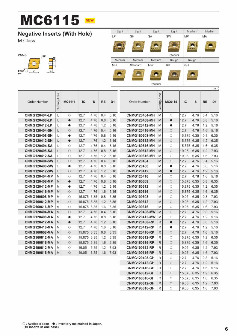
CNMG120404-LP L u 12.7 4.76 0.4 5.16CNMG120408-LP L a 12.7 4.76 0.8 5.16CNMG120412-LP L a 12.7 4.76 1.2 5.16CNMG120404-SH L u 12.7 4.76 0.4 5.16CNMG120408-SH L a 12.7 4.76 0.8 5.16CNMG120412-SH L a 12.7 4.76 1.2 5.16CNMG120404-SA L u 12.7 4.76 0.4 5.16CNMG120408-SA L u 12.7 4.76 0.8 5.16CNMG120412-SA L u 12.7 4.76 1.2 5.16CNMG120404-SW L u 12.7 4.76 0.4 5.16CNMG120408-SW L a 12.7 4.76 0.8 5.16CNMG120412-SW L u 12.7 4.76 1.2 5.16CNMG120404-MP M u 12.7 4.76 0.4 5.16CNMG120408-MP M a 12.7 4.76 0.8 5.16CNMG120412-MP M a 12.7 4.76 1.2 5.16CNMG120416-MP M u 12.7 4.76 1.6 5.16CNMG160608-MP M u 15.875 6.35 0.8 6.35CNMG160612-MP M u 15.875 6.35 1.2 6.35CNMG160616-MP M u 15.875 6.35 1.6 6.35CNMG120404-MA M u 12.7 4.76 0.4 5.16CNMG120408-MA M a 12.7 4.76 0.8 5.16CNMG120412-MA M a 12.7 4.76 1.2 5.16CNMG120416-MA M u 12.7 4.76 1.6 5.16CNMG160608-MA M u 15.875 6.35 0.8 6.35CNMG160612-MA M u 15.875 6.35 1.2 6.35CNMG160616-MA M u 15.875 6.35 1.6 6.35CNMG190612-MA M u 19.05 6.35 1.2 7.93CNMG190616-MA M u 19.05 6.35 1.6 7.93
MC6115 IC S RE D1
CNMG120404-MH M u 12.7 4.76 0.4 5.16CNMG120408-MH M a 12.7 4.76 0.8 5.16CNMG120412-MH M a 12.7 4.76 1.2 5.16CNMG120416-MH M u 12.7 4.76 1.6 5.16CNMG160608-MH M u 15.875 6.35 0.8 6.35CNMG160612-MH M u 15.875 6.35 1.2 6.35CNMG160616-MH M u 15.875 6.35 1.6 6.35CNMG190612-MH M u 19.05 6.35 1.2 7.93CNMG190616-MH M u 19.05 6.35 1.6 7.93CNMG120404 M u 12.7 4.76 0.4 5.16CNMG120408 M a 12.7 4.76 0.8 5.16CNMG120412 M a 12.7 4.76 1.2 5.16CNMG120416 M u 12.7 4.76 1.6 5.16CNMG160608 M u 15.875 6.35 0.8 6.35CNMG160612 M u 15.875 6.35 1.2 6.35CNMG160616 M u 15.875 6.35 1.6 6.35CNMG190608 M u 19.05 6.35 0.8 7.93CNMG190612 M u 19.05 6.35 1.2 7.93CNMG190616 M u 19.05 6.35 1.6 7.93CNMG120408-MW M u 12.7 4.76 0.8 5.16CNMG120412-MW M u 12.7 4.76 1.2 5.16CNMG120408-RP R a 12.7 4.76 0.8 5.16CNMG120412-RP R a 12.7 4.76 1.2 5.16CNMG120416-RP R u 12.7 4.76 1.6 5.16CNMG160612-RP R u 15.875 6.35 1.2 6.35CNMG160616-RP R u 15.875 6.35 1.6 6.35CNMG190612-RP R u 19.05 6.35 1.2 7.93CNMG190616-RP R u 19.05 6.35 1.6 7.93CNMG120408-GH R u 12.7 4.76 0.8 5.16CNMG120412-GH R u 12.7 4.76 1.2 5.16CNMG120416-GH R u 12.7 4.76 1.6 5.16CNMG160612-GH R u 15.875 6.35 1.2 6.35CNMG160616-GH R u 15.875 6.35 1.6 6.35CNMG190612-GH R u 19.05 6.35 1.2 7.93CNMG190616-GH R u 19.05 6.35 1.6 7.93
(mm)
Light Light Light Light Medium Medium
(Wiper)
Medium Medium Medium Rough Rough
Standard
(Wiper)
M Class Negative Inserts (With Hole)
Order Number
Cut
ting
Area
Order Number
Cut
ting
Area
u : Available soon a : Inventory maintained in Japan. (10 inserts in one case)
7
MC6115
SEPSR55º IC
RED1DNMG
LP SH SA
MP MA MH RP GH
MC6115 IC S RE D1
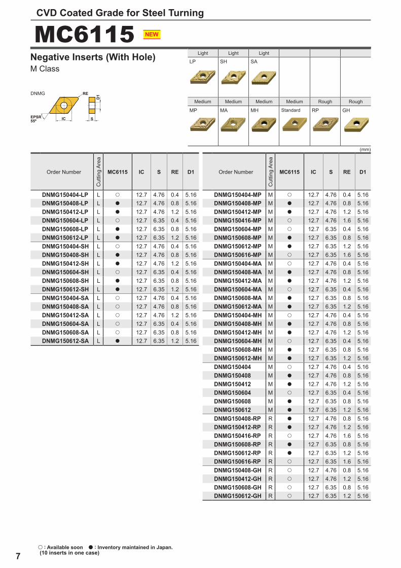
DNMG150404-LP L u 12.7 4.76 0.4 5.16DNMG150408-LP L a 12.7 4.76 0.8 5.16DNMG150412-LP L a 12.7 4.76 1.2 5.16DNMG150604-LP L u 12.7 6.35 0.4 5.16DNMG150608-LP L a 12.7 6.35 0.8 5.16DNMG150612-LP L a 12.7 6.35 1.2 5.16DNMG150404-SH L u 12.7 4.76 0.4 5.16DNMG150408-SH L a 12.7 4.76 0.8 5.16DNMG150412-SH L a 12.7 4.76 1.2 5.16DNMG150604-SH L u 12.7 6.35 0.4 5.16DNMG150608-SH L a 12.7 6.35 0.8 5.16DNMG150612-SH L a 12.7 6.35 1.2 5.16DNMG150404-SA L u 12.7 4.76 0.4 5.16DNMG150408-SA L u 12.7 4.76 0.8 5.16DNMG150412-SA L u 12.7 4.76 1.2 5.16DNMG150604-SA L u 12.7 6.35 0.4 5.16DNMG150608-SA L u 12.7 6.35 0.8 5.16DNMG150612-SA L a 12.7 6.35 1.2 5.16
MC6115 IC S RE D1
DNMG150404-MP M u 12.7 4.76 0.4 5.16DNMG150408-MP M a 12.7 4.76 0.8 5.16DNMG150412-MP M a 12.7 4.76 1.2 5.16DNMG150416-MP M u 12.7 4.76 1.6 5.16DNMG150604-MP M u 12.7 6.35 0.4 5.16DNMG150608-MP M a 12.7 6.35 0.8 5.16DNMG150612-MP M a 12.7 6.35 1.2 5.16DNMG150616-MP M u 12.7 6.35 1.6 5.16DNMG150404-MA M u 12.7 4.76 0.4 5.16DNMG150408-MA M a 12.7 4.76 0.8 5.16DNMG150412-MA M a 12.7 4.76 1.2 5.16DNMG150604-MA M u 12.7 6.35 0.4 5.16DNMG150608-MA M a 12.7 6.35 0.8 5.16DNMG150612-MA M a 12.7 6.35 1.2 5.16DNMG150404-MH M u 12.7 4.76 0.4 5.16DNMG150408-MH M a 12.7 4.76 0.8 5.16DNMG150412-MH M a 12.7 4.76 1.2 5.16DNMG150604-MH M u 12.7 6.35 0.4 5.16DNMG150608-MH M a 12.7 6.35 0.8 5.16DNMG150612-MH M a 12.7 6.35 1.2 5.16DNMG150404 M u 12.7 4.76 0.4 5.16DNMG150408 M a 12.7 4.76 0.8 5.16DNMG150412 M a 12.7 4.76 1.2 5.16DNMG150604 M u 12.7 6.35 0.4 5.16DNMG150608 M a 12.7 6.35 0.8 5.16DNMG150612 M a 12.7 6.35 1.2 5.16DNMG150408-RP R a 12.7 4.76 0.8 5.16DNMG150412-RP R a 12.7 4.76 1.2 5.16DNMG150416-RP R u 12.7 4.76 1.6 5.16DNMG150608-RP R a 12.7 6.35 0.8 5.16DNMG150612-RP R a 12.7 6.35 1.2 5.16DNMG150616-RP R u 12.7 6.35 1.6 5.16DNMG150408-GH R u 12.7 4.76 0.8 5.16DNMG150412-GH R u 12.7 4.76 1.2 5.16DNMG150608-GH R u 12.7 6.35 0.8 5.16DNMG150612-GH R u 12.7 6.35 1.2 5.16
(mm)
CVD Coated Grade for Steel Turning
u : Available soon a : Inventory maintained in Japan. (10 inserts in one case)
Light Light Light
Medium Medium Medium Medium Rough Rough
Standard
M Class Negative Inserts (With Hole)
Order Number
Cut
ting
Area
Order Number
Cut
ting
Area
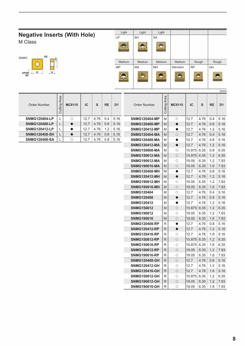
8
SIC
RED1
EPSR90º
SNMG
(mm)
MC6115 IC S RE D1
SNMG120404-LP L u 12.7 4.76 0.4 5.16SNMG120408-LP L a 12.7 4.76 0.8 5.16SNMG120412-LP L a 12.7 4.76 1.2 5.16SNMG120408-SH L a 12.7 4.76 0.8 5.16SNMG120408-SA L u 12.7 4.76 0.8 5.16
MC6115 IC S RE D1
SNMG120404-MP M u 12.7 4.76 0.4 5.16SNMG120408-MP M a 12.7 4.76 0.8 5.16SNMG120412-MP M a 12.7 4.76 1.2 5.16SNMG120404-MA M u 12.7 4.76 0.4 5.16SNMG120408-MA M a 12.7 4.76 0.8 5.16SNMG120412-MA M a 12.7 4.76 1.2 5.16SNMG150608-MA M u 15.875 6.35 0.8 6.35SNMG150612-MA M u 15.875 6.35 1.2 6.35SNMG190612-MA M u 19.05 6.35 1.2 7.93SNMG190616-MA M u 19.05 6.35 1.6 7.93SNMG120408-MH M a 12.7 4.76 0.8 5.16SNMG120412-MH M a 12.7 4.76 1.2 5.16SNMG190612-MH M u 19.05 6.35 1.2 7.93SNMG190616-MH M u 19.05 6.35 1.6 7.93SNMG120404 M u 12.7 4.76 0.4 5.16SNMG120408 M a 12.7 4.76 0.8 5.16SNMG120412 M a 12.7 4.76 1.2 5.16SNMG150612 M u 15.875 6.35 1.2 6.35SNMG190612 M u 19.05 6.35 1.2 7.93SNMG190616 M u 19.05 6.35 1.6 7.93SNMG120408-RP R a 12.7 4.76 0.8 5.16SNMG120412-RP R a 12.7 4.76 1.2 5.16SNMG120416-RP R u 12.7 4.76 1.6 5.16SNMG150612-RP R u 15.875 6.35 1.2 6.35SNMG150616-RP R u 15.875 6.35 1.6 6.35SNMG190612-RP R u 19.05 6.35 1.2 7.93SNMG190616-RP R u 19.05 6.35 1.6 7.93SNMG120408-GH R u 12.7 4.76 0.8 5.16SNMG120412-GH R u 12.7 4.76 1.2 5.16SNMG120416-GH R u 12.7 4.76 1.6 5.16SNMG150612-GH R u 15.875 6.35 1.2 6.35SNMG190612-GH R u 19.05 6.35 1.2 7.93SNMG190616-GH R u 19.05 6.35 1.6 7.93
LP SH SA
MP MA MH RP GH
M Class Negative Inserts (With Hole)
Order Number
Cut
ting
Area
Order Number
Cut
ting
Area
Light Light Light
Medium Medium Medium Medium Rough Rough
Standard
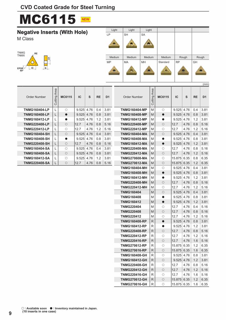
9
MC6115
EPSR60º
S
D1
RE
IC
TNMGTNMX
(mm)
LP SH SA
MP MA MH RP GH
MC6115 IC S RE D1
TNMG160404-LP L u 9.525 4.76 0.4 3.81TNMG160408-LP L a 9.525 4.76 0.8 3.81TNMG160412-LP L a 9.525 4.76 1.2 3.81TNMG220408-LP L u 12.7 4.76 0.8 5.16TNMG220412-LP L u 12.7 4.76 1.2 5.16TNMG160404-SH L u 9.525 4.76 0.4 3.81TNMG160408-SH L a 9.525 4.76 0.8 3.81TNMG220408-SH L u 12.7 4.76 0.8 5.16TNMG160404-SA L u 9.525 4.76 0.4 3.81TNMG160408-SA L u 9.525 4.76 0.8 3.81TNMG160412-SA L u 9.525 4.76 1.2 3.81TNMG220408-SA L u 12.7 4.76 0.8 5.16
MC6115 IC S RE D1
TNMG160404-MP M u 9.525 4.76 0.4 3.81TNMG160408-MP M a 9.525 4.76 0.8 3.81TNMG160412-MP M a 9.525 4.76 1.2 3.81TNMG220408-MP M u 12.7 4.76 0.8 5.16TNMG220412-MP M u 12.7 4.76 1.2 5.16TNMG160404-MA M u 9.525 4.76 0.4 3.81TNMG160408-MA M a 9.525 4.76 0.8 3.81TNMG160412-MA M a 9.525 4.76 1.2 3.81TNMG220408-MA M u 12.7 4.76 0.8 5.16TNMG220412-MA M u 12.7 4.76 1.2 5.16TNMG270608-MA M u 15.875 6.35 0.8 6.35TNMG270612-MA M u 15.875 6.35 1.2 6.35TNMG160404-MH M u 9.525 4.76 0.4 3.81TNMG160408-MH M a 9.525 4.76 0.8 3.81TNMG160412-MH M a 9.525 4.76 1.2 3.81TNMG220408-MH M u 12.7 4.76 0.8 5.16TNMG220412-MH M u 12.7 4.76 1.2 5.16TNMG160404 M u 9.525 4.76 0.4 3.81TNMG160408 M a 9.525 4.76 0.8 3.81TNMG160412 M a 9.525 4.76 1.2 3.81TNMG220404 M u 12.7 4.76 0.4 5.16TNMG220408 M u 12.7 4.76 0.8 5.16TNMG220412 M u 12.7 4.76 1.2 5.16TNMG160408-RP R a 9.525 4.76 0.8 3.81TNMG160412-RP R a 9.525 4.76 1.2 3.81TNMG220408-RP R u 12.7 4.76 0.8 5.16TNMG220412-RP R u 12.7 4.76 1.2 5.16TNMG220416-RP R u 12.7 4.76 1.6 5.16TNMG270612-RP R u 15.875 6.35 1.2 6.35TNMG270616-RP R u 15.875 6.35 1.6 6.35TNMG160408-GH R u 9.525 4.76 0.8 3.81TNMG160412-GH R u 9.525 4.76 1.2 3.81TNMG220408-GH R u 12.7 4.76 0.8 5.16TNMG220412-GH R u 12.7 4.76 1.2 5.16TNMG220416-GH R u 12.7 4.76 1.6 5.16TNMG270612-GH R u 15.875 6.35 1.2 6.35TNMG270616-GH R u 15.875 6.35 1.6 6.35
CVD Coated Grade for Steel Turning
u : Available soon a : Inventory maintained in Japan. (10 inserts in one case)
M Class Negative Inserts (With Hole)Negative Inserts (With Hole) Light Light Light
Medium Medium Medium Medium Rough Rough
Standard
Order Number
Cut
ting
Area
Order Number
Cut
ting
Area
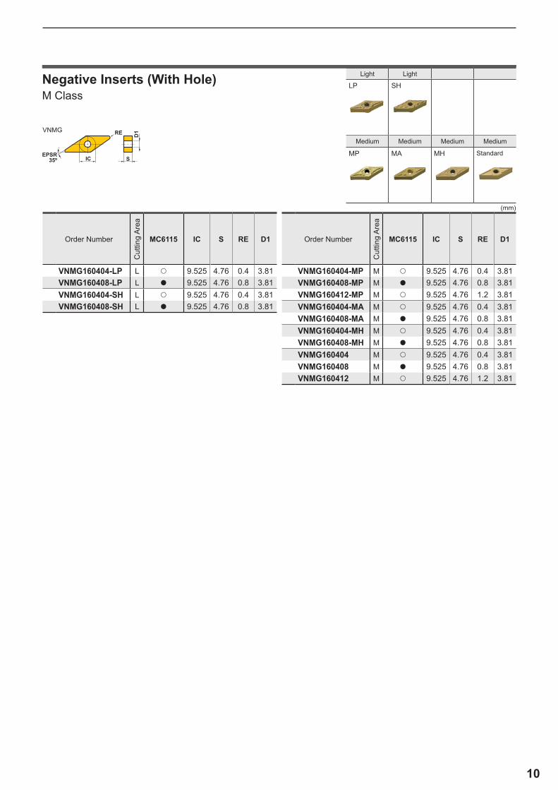
10
SIC
D1
EPSR35º
REVNMG
LP SH
MP MA MH
(mm)
MC6115 IC S RE D1
VNMG160404-LP L u 9.525 4.76 0.4 3.81VNMG160408-LP L a 9.525 4.76 0.8 3.81VNMG160404-SH L u 9.525 4.76 0.4 3.81VNMG160408-SH L a 9.525 4.76 0.8 3.81
MC6115 IC S RE D1
VNMG160404-MP M u 9.525 4.76 0.4 3.81VNMG160408-MP M a 9.525 4.76 0.8 3.81VNMG160412-MP M u 9.525 4.76 1.2 3.81VNMG160404-MA M u 9.525 4.76 0.4 3.81VNMG160408-MA M a 9.525 4.76 0.8 3.81VNMG160404-MH M u 9.525 4.76 0.4 3.81VNMG160408-MH M a 9.525 4.76 0.8 3.81VNMG160404 M u 9.525 4.76 0.4 3.81VNMG160408 M a 9.525 4.76 0.8 3.81VNMG160412 M u 9.525 4.76 1.2 3.81
Light Light
Medium Medium Medium Medium
Standard
M Class Negative Inserts (With Hole)
Order Number
Cut
ting
Area
Order Number
Cut
ting
Area
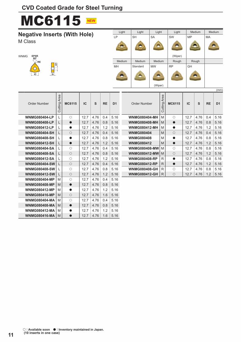
11
MC6115
RE
EPSR80º
SIC
D1
WNMG
LP SH SA SW MP MA
MH MW RP GH
(mm)
MC6115 IC S RE D1
WNMG080404-LP L u 12.7 4.76 0.4 5.16WNMG080408-LP L a 12.7 4.76 0.8 5.16WNMG080412-LP L a 12.7 4.76 1.2 5.16WNMG080404-SH L u 12.7 4.76 0.4 5.16WNMG080408-SH L a 12.7 4.76 0.8 5.16WNMG080412-SH L a 12.7 4.76 1.2 5.16WNMG080404-SA L u 12.7 4.76 0.4 5.16WNMG080408-SA L u 12.7 4.76 0.8 5.16WNMG080412-SA L u 12.7 4.76 1.2 5.16WNMG080404-SW L u 12.7 4.76 0.4 5.16WNMG080408-SW L u 12.7 4.76 0.8 5.16WNMG080412-SW L u 12.7 4.76 1.2 5.16WNMG080404-MP M u 12.7 4.76 0.4 5.16WNMG080408-MP M a 12.7 4.76 0.8 5.16WNMG080412-MP M a 12.7 4.76 1.2 5.16WNMG080416-MP M u 12.7 4.76 1.6 5.16WNMG080404-MA M u 12.7 4.76 0.4 5.16WNMG080408-MA M a 12.7 4.76 0.8 5.16WNMG080412-MA M a 12.7 4.76 1.2 5.16WNMG080416-MA M a 12.7 4.76 1.6 5.16
MC6115 IC S RE D1
WNMG080404-MH M u 12.7 4.76 0.4 5.16WNMG080408-MH M a 12.7 4.76 0.8 5.16WNMG080412-MH M a 12.7 4.76 1.2 5.16WNMG080404 M u 12.7 4.76 0.4 5.16WNMG080408 M a 12.7 4.76 0.8 5.16WNMG080412 M a 12.7 4.76 1.2 5.16WNMG080408-MW M u 12.7 4.76 0.8 5.16WNMG080412-MW M u 12.7 4.76 1.2 5.16WNMG080408-RP R a 12.7 4.76 0.8 5.16WNMG080412-RP R a 12.7 4.76 1.2 5.16WNMG080408-GH R u 12.7 4.76 0.8 5.16WNMG080412-GH R u 12.7 4.76 1.2 5.16
CVD Coated Grade for Steel Turning
u : Available soon a : Inventory maintained in Japan. (10 inserts in one case)
Light Light Light Light Medium Medium
(Wiper)
Medium Medium Medium Rough Rough
Standard
(Wiper)
M Class Negative Inserts (With Hole)
Order Number
Cut
ting
Area
Order Number
Cut
ting
Area
12
0
0.05
0.1
0.15
0.2
0.25
0.3
0.35
2 4 6 8 10 12 14 16
MC6115MA Br
MC6115MA Br
MC6115
Cutting Performance
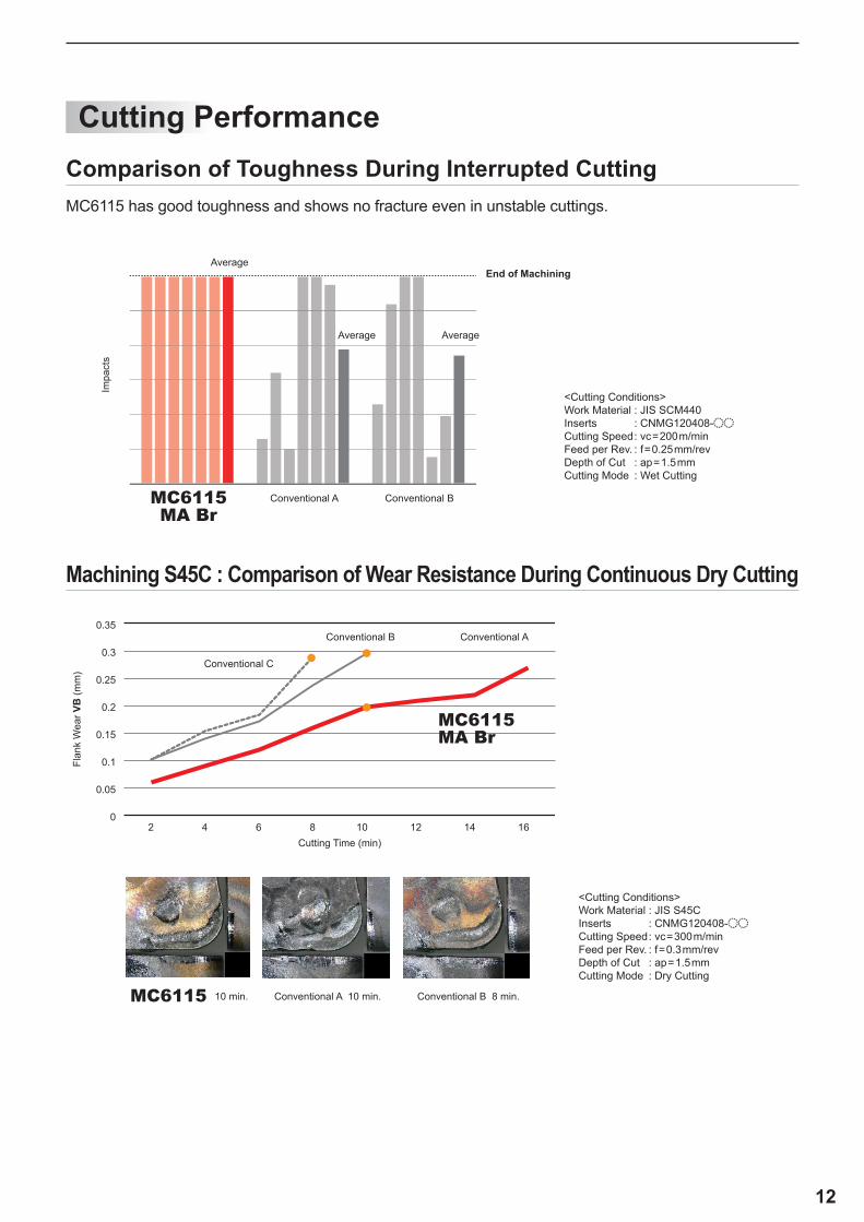
<Cutting Conditions> Work Material : JIS SCM440 Inserts : CNMG120408-oo Cutting Speed : vc=200m/min Feed per Rev. : f=0.25mm/rev Depth of Cut : ap=1.5mm Cutting Mode : Wet Cutting
Impa
cts
Conventional A Conventional B
AverageAverage
AverageEnd of Machining
<Cutting Conditions> Work Material : JIS S45C Inserts : CNMG120408-oo Cutting Speed : vc=300m/min Feed per Rev. : f=0.3mm/rev Depth of Cut : ap=1.5mm Cutting Mode : Dry Cutting
Cutting Time (min)
Flan
k W
ear V
B (m
m)
Conventional A
Conventional C
Conventional B
Conventional A 10 min. Conventional B 8 min.10 min.
MC6115 has good toughness and shows no fracture even in unstable cuttings.
Comparison of Toughness During Interrupted Cutting
Machining S45C : Comparison of Wear Resistance During Continuous Dry Cutting
13
0
0.1
0.2
0.3
0.4
0.5
2 4 6 7 8 10 12 14
0
0.05
0.1
0.15
0.2
0.25
0.3
0.35
2 4 6 8 10 12 14 16 18 20 22 24 26 28 30 32
MC6115
MC6115
MC6115MA Br
MC6115MH Br
CVD Coated Grade for Steel Turning
Cutting Performance
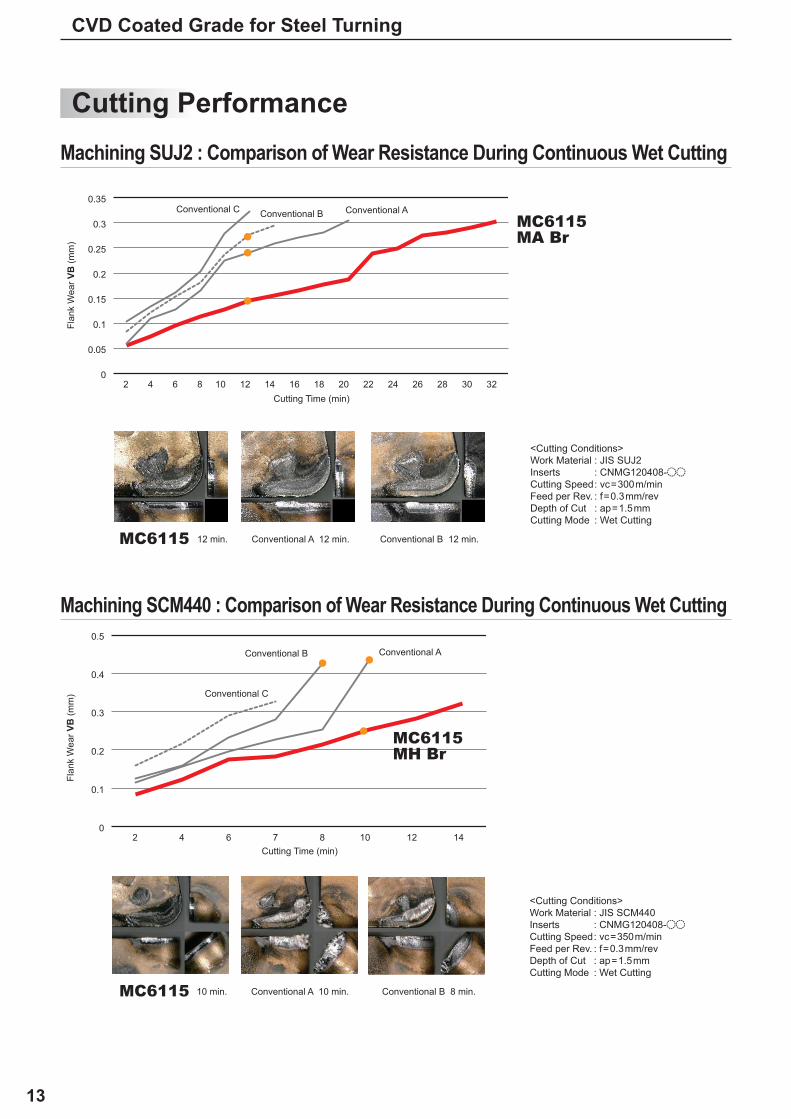
<Cutting Conditions> Work Material : JIS SUJ2 Inserts : CNMG120408-oo Cutting Speed : vc=300m/min Feed per Rev. : f=0.3mm/rev Depth of Cut : ap=1.5mm Cutting Mode : Wet Cutting
<Cutting Conditions> Work Material : JIS SCM440 Inserts : CNMG120408-oo Cutting Speed : vc=350m/min Feed per Rev. : f=0.3mm/rev Depth of Cut : ap=1.5mm Cutting Mode : Wet Cutting
Cutting Time (min)
Cutting Time (min)
Flan
k W
ear V
B (m
m)
Flan
k W
ear V
B (m
m)
Conventional A
Conventional A
Conventional C
Conventional C
Conventional B
Conventional B
Conventional A 12 min.
Conventional A 10 min.
Conventional B 12 min.
Conventional B 8 min.
12 min.
10 min.
Machining SUJ2 : Comparison of Wear Resistance During Continuous Wet Cutting
Machining SCM440 : Comparison of Wear Resistance During Continuous Wet Cutting
14
CNMG120408-MA WNMG080408-MA
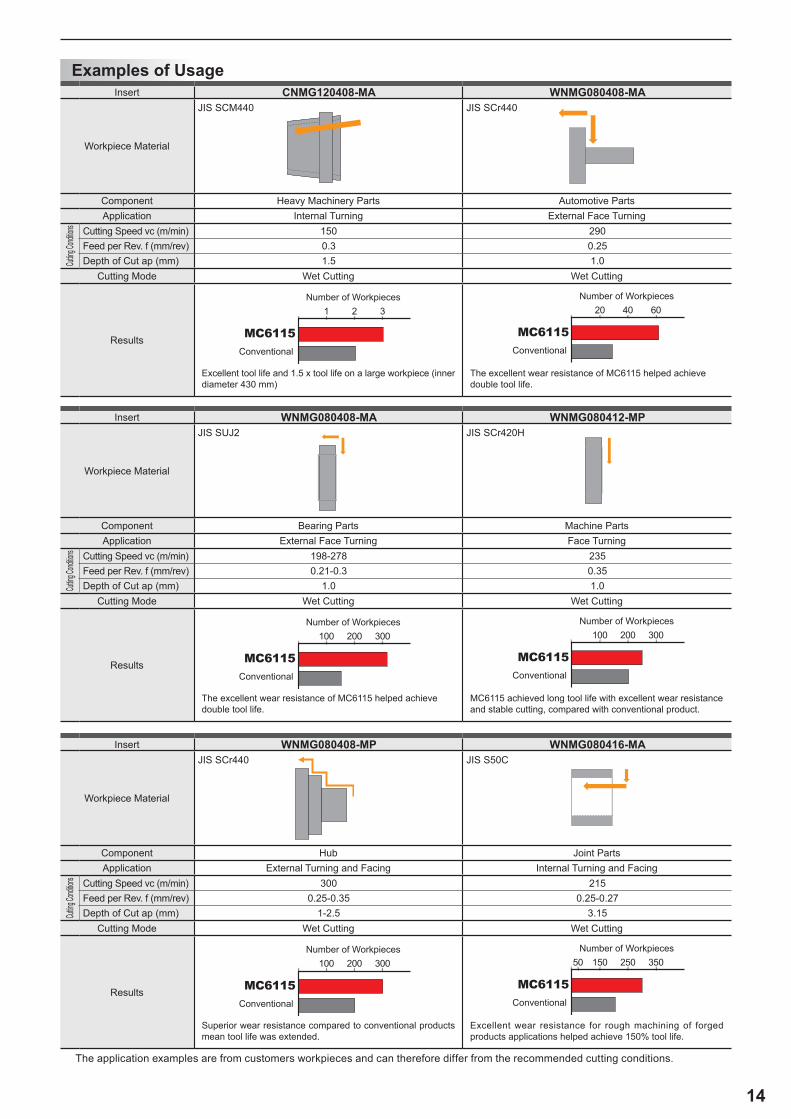
150 2900.3 0.251.5 1.0
WNMG080408-MA WNMG080412-MP
198-278 2350.21-0.3 0.35
1.0 1.0
WNMG080408-MP WNMG080416-MA
300 2150.25-0.35 0.25-0.27
1-2.5 3.15
MC6115
MC6115
MC6115
MC6115
MC6115
MC6115
1 2 3
100 200 300
100 200 300
20 40 60
100 200 300
15050 250 350
The application examples are from customers workpieces and can therefore differ from the recommended cutting conditions.
Examples of UsageInsert
Workpiece Material
JIS SCM440 JIS SCr440
Component Heavy Machinery Parts Automotive PartsApplication Internal Turning External Face Turning
Cutting
Condit
ions Cutting Speed vc (m/min)Feed per Rev. f (mm/rev)Depth of Cut ap (mm)
Cutting Mode Wet Cutting Wet Cutting
Results
Excellent tool life and 1.5 x tool life on a large workpiece (inner diameter 430 mm)
The excellent wear resistance of MC6115 helped achieve double tool life.
Insert
Workpiece Material
JIS SUJ2 JIS SCr420H
Component Bearing Parts Machine PartsApplication External Face Turning Face Turning
Cutting
Condit
ions Cutting Speed vc (m/min)Feed per Rev. f (mm/rev)Depth of Cut ap (mm)
Cutting Mode Wet Cutting Wet Cutting
Results
The excellent wear resistance of MC6115 helped achieve double tool life.
MC6115 achieved long tool life with excellent wear resistance and stable cutting, compared with conventional product.
Insert
Workpiece Material
JIS SCr440 JIS S50C
Component Hub Joint PartsApplication External Turning and Facing Internal Turning and Facing
Cutting
Condit
ions Cutting Speed vc (m/min)Feed per Rev. f (mm/rev)Depth of Cut ap (mm)
Cutting Mode Wet Cutting Wet Cutting
Results
Superior wear resistance compared to conventional products mean tool life was extended.
Excellent wear resistance for rough machining of forged products applications helped achieve 150% tool life.
Conventional
Conventional
Conventional
Conventional
Conventional
Conventional
Number of Workpieces
Number of Workpieces
Number of Workpieces
Number of Workpieces
Number of Workpieces
Number of Workpieces
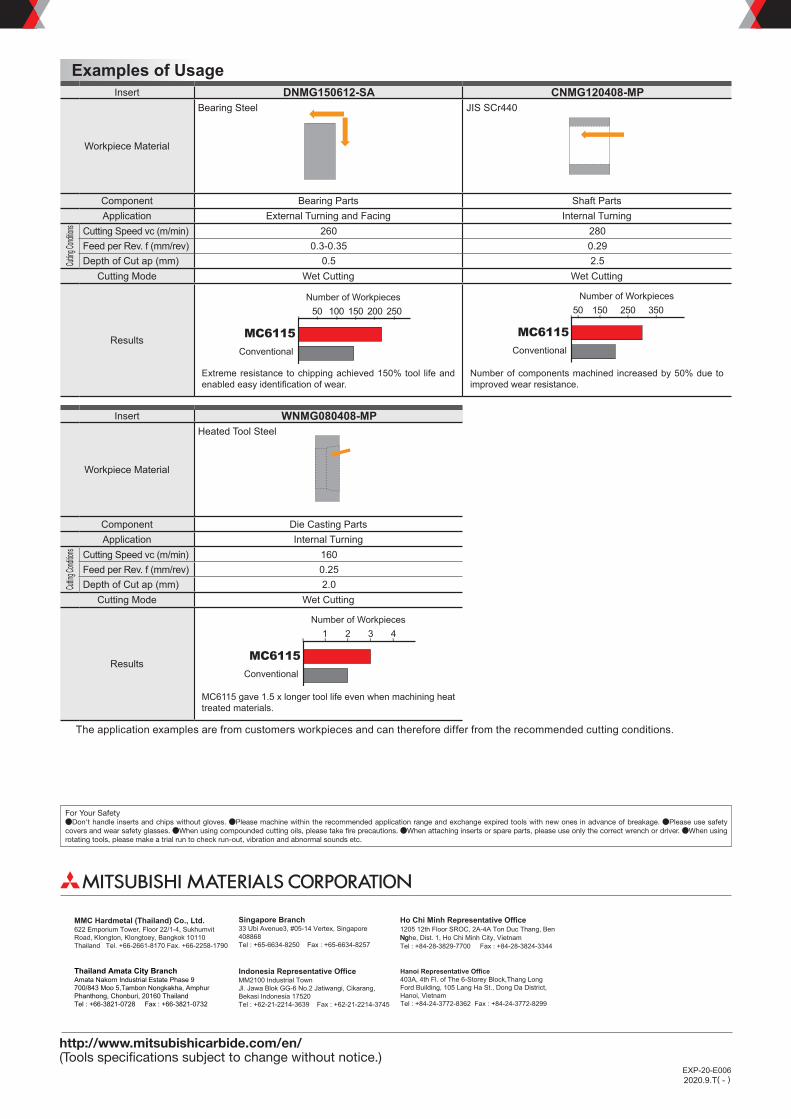
DNMG150612-SA CNMG120408-MP
260 2800.3-0.35 0.29
0.5 2.5
WNMG080408-MP
1600.252.0
MC6115 MC6115
MC6115
50 100 150 200 250 15050 250 350
1 2 3 4
For Your SafetyaDon't handle inserts and chips without gloves. aPlease machine within the recommended application range and exchange expired tools with new ones in advance of breakage. aPlease use safety covers and wear safety glasses. aWhen using compounded cutting oils, please take fire precautions. aWhen attaching inserts or spare parts, please use only the correct wrench or driver. aWhen using rotating tools, please make a trial run to check run-out, vibration and abnormal sounds etc.
http://www.mitsubishicarbide.com/en/(Tools specifications subject to change without notice.)
2020.9.T( - )EXP-20-E006
Examples of UsageInsert
Workpiece Material
Bearing Steel JIS SCr440
Component Bearing Parts Shaft PartsApplication External Turning and Facing Internal Turning
Cutting
Condit
ions Cutting Speed vc (m/min)Feed per Rev. f (mm/rev)Depth of Cut ap (mm)
Cutting Mode Wet Cutting Wet Cutting
Results
Extreme resistance to chipping achieved 150% tool life and enabled easy identification of wear.
Number of components machined increased by 50% due to improved wear resistance.
Insert
Workpiece Material
Heated Tool Steel
Component Die Casting PartsApplication Internal Turning
Cutting
Condit
ions Cutting Speed vc (m/min)Feed per Rev. f (mm/rev)Depth of Cut ap (mm)
Cutting Mode Wet Cutting
Results
MC6115 gave 1.5 x longer tool life even when machining heat treated materials.
Conventional Conventional
Conventional
Number of Workpieces Number of Workpieces
Number of Workpieces
The application examples are from customers workpieces and can therefore differ from the recommended cutting conditions.
MMC Hardmetal (Thailand) Co., Ltd. 622 Emporium Tower, Floor 22/1-4, Sukhumvit Road, Klongton, Klongtoey, Bangkok 10110 Thailand Tel. +66-2661-8170 Fax. +66-2258-1790
Thailand Amata City BranchAmata Nakorn Industrial Estate Phase 9 700/843 Moo 5,Tambon Nongkakha, Amphur Phanthong, Chonburi, 20160 Thailand Tel : +66-3821-0728 Fax : +66-3821-0732
Singapore Branch33 Ubi Avenue3, #05-14 Vertex, Singapore 408868Tel : +65-6634-8250 Fax : +65-6634-8257
Indonesia Representative Office MM2100 Industrial TownJl. Jawa Blok GG-6 No.2 Jatiwangi, Cikarang, Bekasi Indonesia 17520Tel : +62-21-2214-3639 Fax : +62-21-2214-3745
Ho Chi Minh Representative Office 1205 12th Floor SROC, 2A-4A Ton Duc Thang, Ben NgNghe, Dist. 1, Ho Chi Minh City, VietnamTel : +84-28-3829-7700 Fax : +84-28-3824-3344
Hanoi Representative Office403A, 4th Fl. of The 6-Storey Block,Thang Long Ford Building, 105 Lang Ha St., Dong Da District, Hanoi, VietnamTel : +84-24-3772-8362 Fax : +84-24-3772-8299