may 27, 2021 advanced mechanical elements
TRANSCRIPT
0
May 27, 2021
Advanced Mechanical Elements(Lecture 7)
Kinetostatic analysis and motion control of underactuated wire-driven mechanisms - Motion control of wire-driven underactuated
mechanisms under gravitational force -
Tokyo Institute of TechnologyDept. of Mechanical EngineeringSchool of Engineering
Prof. Nobuyuki Iwatsuki
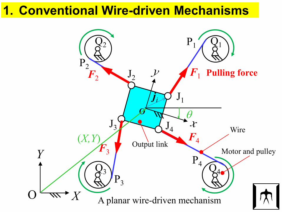
1. Conventional Wire-driven Mechanisms
A planar wire-driven mechanismO
Y
X
Output linkMotor and pulley
Wire
J1
J2
J3 J4
F1 Pulling forceF2
F3
F4
θ
(X,Y)
Q1Q2
Q3 Q4
ji
P1
P2
P3
P4
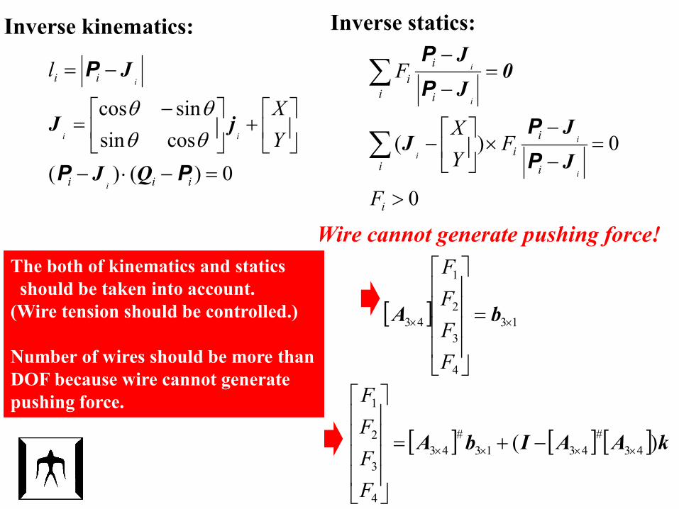
Inverse kinematics:
0)()(cossinsincos
=−⋅−
+
−=
−=
iii
ii
i
ii
i
YX
l
PP
P
QJ
jJ
J
θθθθ
Inverse statics:
0
0)(
>
=−
−×
−
=−
−
∑
∑
i
i i
ii
i
i
ii
F
FYX
F
i
i
i
i
i
JJ
J
0JJ
PP
PP
Wire cannot generate pushing force!
[ ] 13
4
3
2
1
43 ×× =
bA
FFFF
[ ] [ ] [ ] kAAIbA )( 43#
4313#
43
4
3
2
1
×××× −+=
FFFF
The both of kinematics and statics should be taken into account.
(Wire tension should be controlled.)
Number of wires should be more thanDOF because wire cannot generate pushing force.
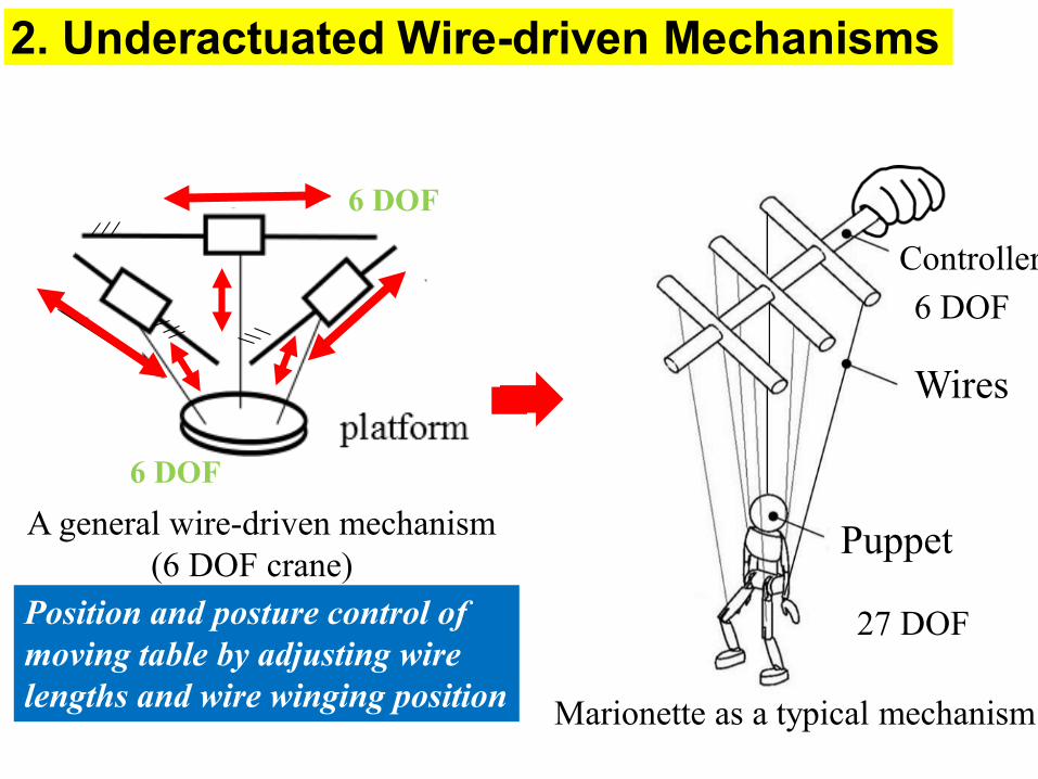
2. Underactuated Wire-driven Mechanisms
A general wire-driven mechanism(6 DOF crane)
Position and posture control of moving table by adjusting wire lengths and wire winging position
An example of underactuatedwire-driven mechanism
Control link chain (4 DOF)
Output link chain (5 DOF)
Output link chain can be driven with wires with constant length“Underactuated mechanism”
27 DOF
6 DOFController
Wires
Puppet
Marionette as a typical mechanism
6 DOF
6 DOF
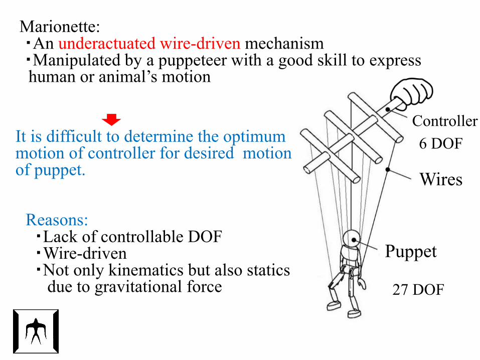
Marionette:・An underactuated wire-driven mechanism・Manipulated by a puppeteer with a good skill to expresshuman or animal’s motion
27 DOF
6 DOFController
Wires
Puppet
Reasons:・Lack of controllable DOF・Wire-driven ・Not only kinematics but also statics
due to gravitational force
It is difficult to determine the optimum motion of controller for desired motionof puppet.
27 DOF
6 DOFController
Wires
Puppet
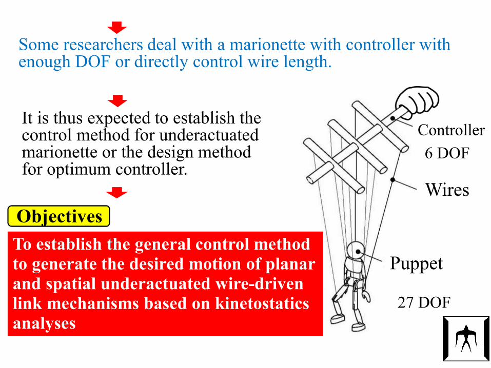
Some researchers deal with a marionette with controller with enough DOF or directly control wire length.
It is thus expected to establish the control method for underactuatedmarionette or the design method for optimum controller.
Objectives To establish the general control method to generate the desired motion of planar and spatial underactuated wire-driven link mechanisms based on kinetostaticsanalyses
3. Kinetostatics Analysis of UnderactuatedWire-driven Mechanisms
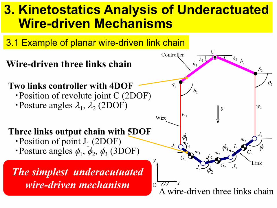
3.1 Example of planar wire-driven link chain
Wire-driven three links chain
The simplest underacutuatedwire-driven mechanism
φ
A wire-driven three links chain
φ1
φ2
φ3
Two links controller with 4DOF・Position of revolute joint C (2DOF)・Posture angles λ1, λ2 (2DOF)
Three links output chain with 5DOF・Position of point J1 (2DOF)・Posture angles φ1, φ2, φ3 (3DOF)
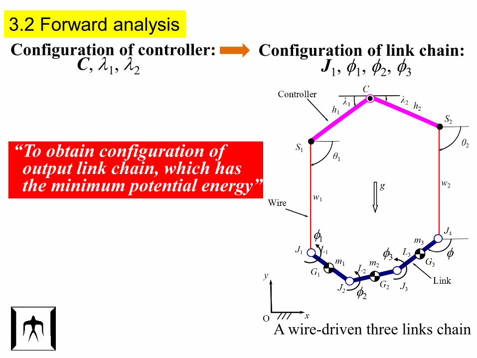
3.2 Forward analysis Configuration of controller: Configuration of link chain:
J1, φ1, φ2, φ3C, λ1, λ2
“To obtain configuration of output link chain, which has the minimum potential energy”
φ
A wire-driven three links chain
φ1
φ2
φ3
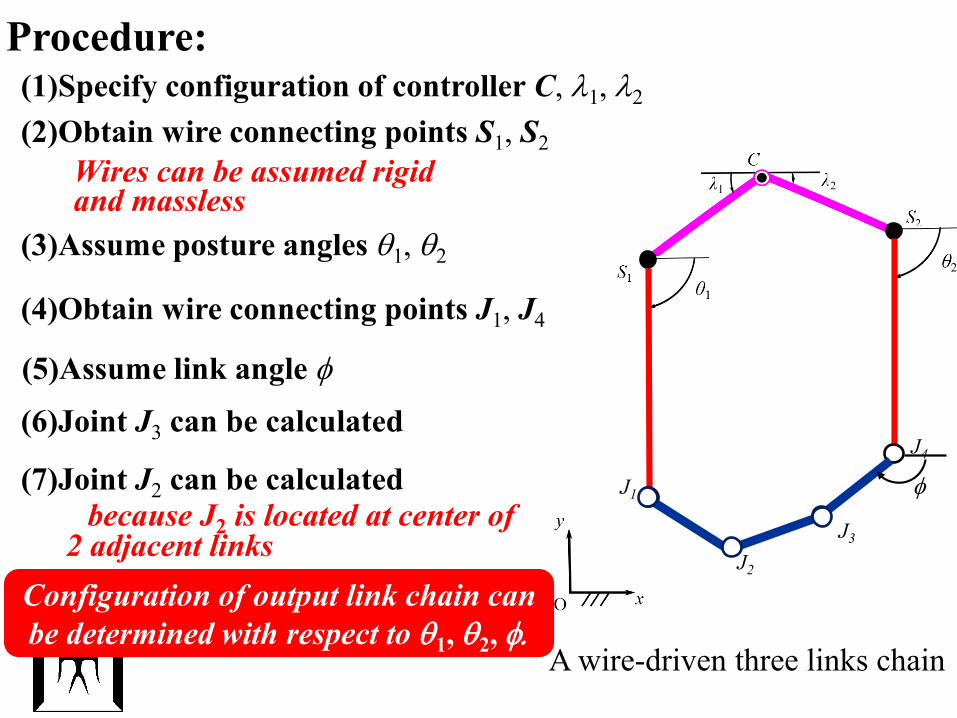
(2)Obtain wire connecting points S1, S2
(3)Assume posture angles θ1, θ2
Procedure:(1)Specify configuration of controller C, λ1, λ2
(4)Obtain wire connecting points J1, J4
J4
J1
(5)Assume link angle φ
φ(7)Joint J2 can be calculated
J2
because J2 is located at center of2 adjacent links
(6)Joint J3 can be calculated
J3
Wires can be assumed rigid and massless
Configuration of output link chain can be determined with respect to θ1, θ2, φ.
A wire-driven three links chain
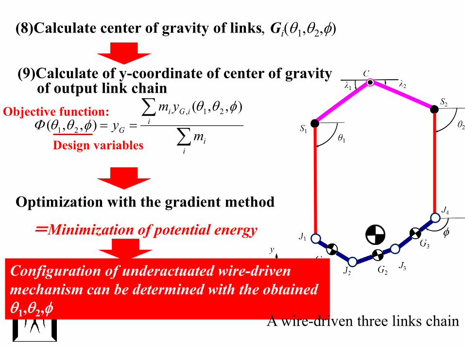
(8)Calculate center of gravity of links, Gi(θ1,θ2,φ)
Optimization with the gradient method
=Minimization of potential energy
Design variables
Objective function:
Configuration of underactuated wire-driven mechanism can be determined with the obtainedθ1,θ2,φ
φ
A wire-driven three links chain
(9)Calculate of y-coordinate of center of gravity of output link chain
∑∑
==
ii
iiGi
G m
ymy
),,(),,(
21,
21
φθθφθθΦ
10
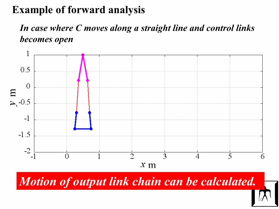
In case where C moves along a straight line and control links becomes open
Motion of output link chain can be calculated.
Example of forward analysis
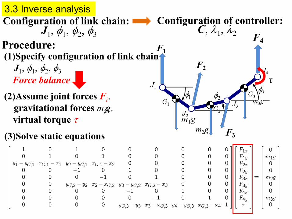
3.3 Inverse analysis Configuration of controller:Configuration of link chain:
J1, φ1, φ2, φ3 C, λ1, λ2
Force balance
(3)Solve static equations
=×−+×−−=++−=×−+×−−=++−
=×−+×−=++
,
τ434333343
323222232
212111121
)()(0)()( ,
0)()(,
FGJFGJgFFFGJFGJgFF
FGJFGJgFF
00
0
mmm
Procedure:(1)Specify configuration of link chain
J1, φ1, φ2, φ3
φ1 φ2φ3(2)Assume joint forces Fi,
gravitational forces mig,virtual torque τ
12
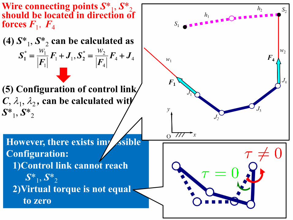
Wire connecting points S*1, S*2should be located in direction of forces F1,F4
(5) Configuration of control link, C, λ1, λ2 , can be calculated with S*1, S*2
However, there exists impossibleConfiguration:
1)Control link cannot reachS*1, S*2
2)Virtual torque is not equal to zero
(4) S*1, S*2 can be calculated as
444
211
1
1 , JFF
SJFF
S +=+=ww *
2*1
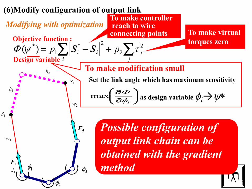
(6)Modify configuration of output link
∑∑ +−=j
ji
i pp 22
2*1
*)( τψΦ iSS
Modifying with optimization
Design variable
Objective function :
To make controllerreach to wire
connecting points To make virtual torques zero
Possible configuration of output link chain can be obtained with the gradient methodφ3
φ2
φ1
∂∂
iφΦmax as design variable φi→ψ∗
Set the link angle which has maximum sensitivityTo make modification small
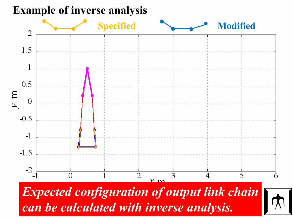
Example of inverse analysis
Expected configuration of output link chain can be calculated with inverse analysis.
Specified Modified
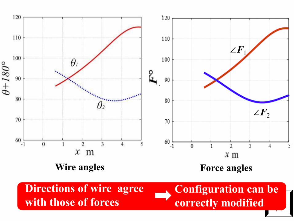
Configuration can be correctly modified
Directions of wire agree with those of forces
Wire angles Virtual torque before andafter modificationForce angles
∠F1
∠F2

16
Let’s have a 10 minutes break here!
If possible, would you please answer to 2021 1QCourse Survey of Study Effectiveness for this course‘Advanced Mechanical Elements’ now?
The web-site to answer the survey is as follows:
https://www.ks-fdcenter.net/fmane_titech/Ans?ms=t&id=titech&cd=tNCE234B
The deadline to answer is June 10, Thursday.
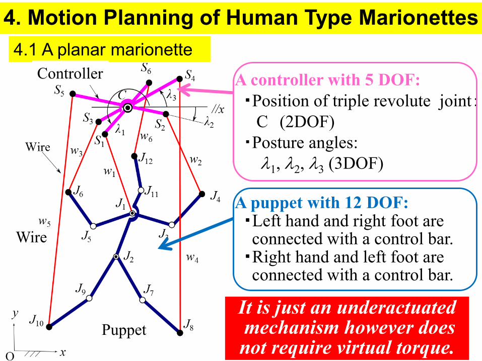
4. Motion Planning of Human Type Marionettes4.1 A planar marionette
A controller with 5 DOF:・Position of triple revolute joint:
C (2DOF)・Posture angles:
λ1, λ2, λ3 (3DOF)
A puppet with 12 DOF:・Left hand and right foot are connected with a control bar.・Right hand and left foot are connected with a control bar.
Wire
Controller
PuppetIt is just an underactuatedmechanism however does not require virtual torque.
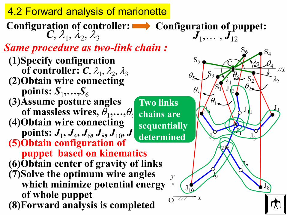
4.2 Forward analysis of marionette Configuration of controller: Configuration of puppet:
J1,… , J12C, λ1, λ2, λ3Same procedure as two-link chain : (1)Specify configuration
of controller: C, λ1, λ2, λ3(2)Obtain wire connecting
points: S1,…,S6(3)Assume posture angles
of massless wires, θ1,…,θ6(4)Obtain wire connecting
points: J1, J4, J6, J8, J10, J12(5)Obtain configuration of
puppet based on kinematics(6)Obtain center of gravity of links(7)Solve the optimum wire angles
which minimize potential energyof whole puppet
(8)Forward analysis is completed
θ1
θ5θ2
θ4
θ3
θ6
Two links chains are sequentially determined
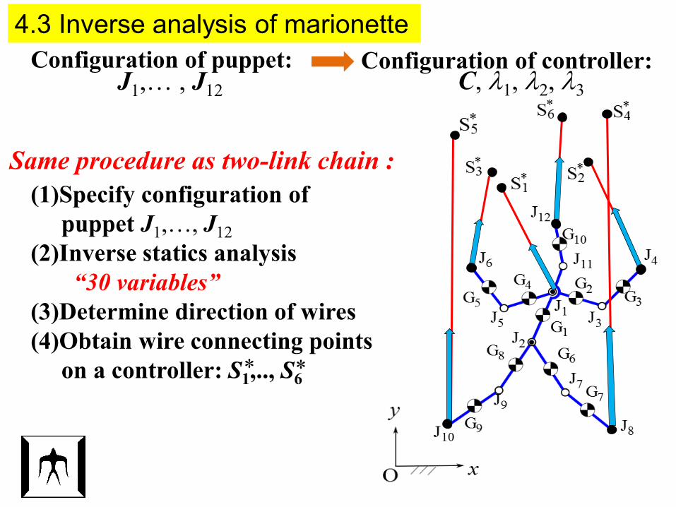
4.3 Inverse analysis of marionette Configuration of controller:Configuration of puppet:
J1,… , J12 C, λ1, λ2, λ3
Same procedure as two-link chain : (1)Specify configuration of
puppet J1,…, J12(2)Inverse statics analysis
“30 variables”(3)Determine direction of wires(4)Obtain wire connecting points
on a controller: S1,.., S6* *
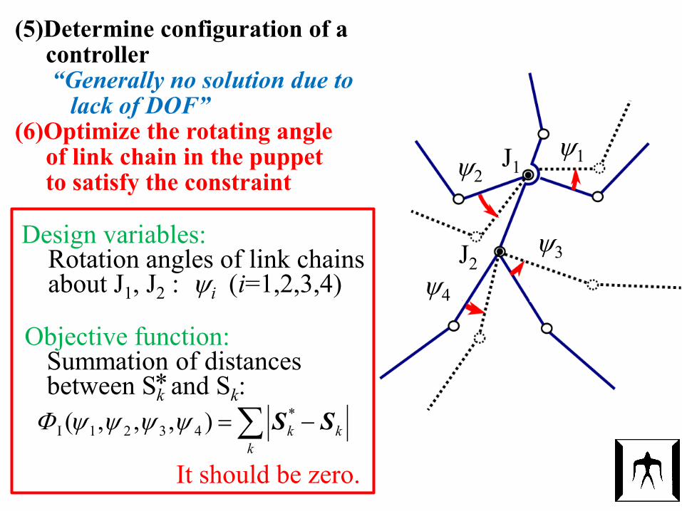
(5)Determine configuration of a controller “Generally no solution due to
lack of DOF”(6)Optimize the rotating angle
of link chain in the puppetto satisfy the constraint
Design variables:Rotation angles of link chainsabout J1, J2 : ψi (i=1,2,3,4)
∑ −=k
kk SS*4321I ),,,( ψψψψΦ
*
Objective function:Summation of distances between Sk and Sk:
It should be zero.
ψ2 ψ1
ψ4
ψ3
J1
J2
21
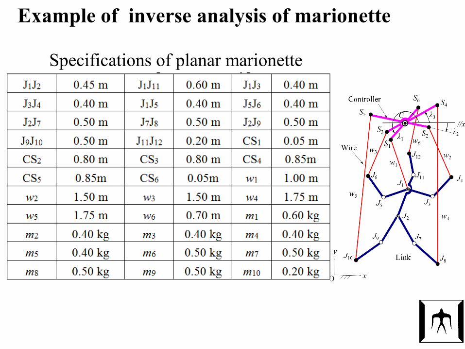
Example of inverse analysis of marionette
Specifications of planar marionette
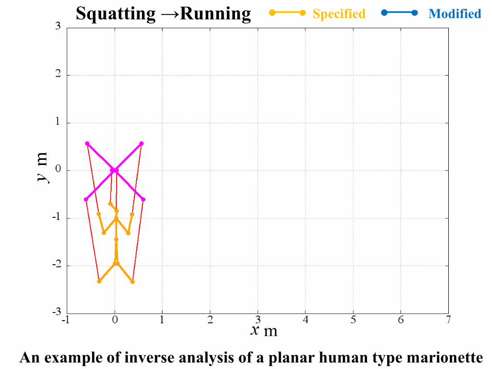
An example of inverse analysis of a planar human type marionette
Specified Modified Squatting →Running
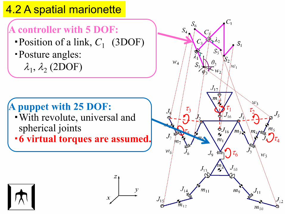
4.2 A spatial marionette
A controller with 5 DOF:・Position of a link, C1 (3DOF)・Posture angles:
λ1, λ2 (2DOF)
τ1 τ2τ3
τ4
τ5
τ6
A puppet with 25 DOF:・With revolute, universal andspherical joints・6 virtual torques are assumed.
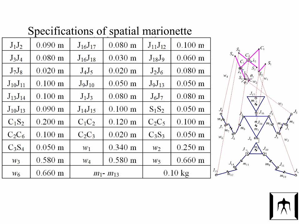
Specifications of spatial marionette
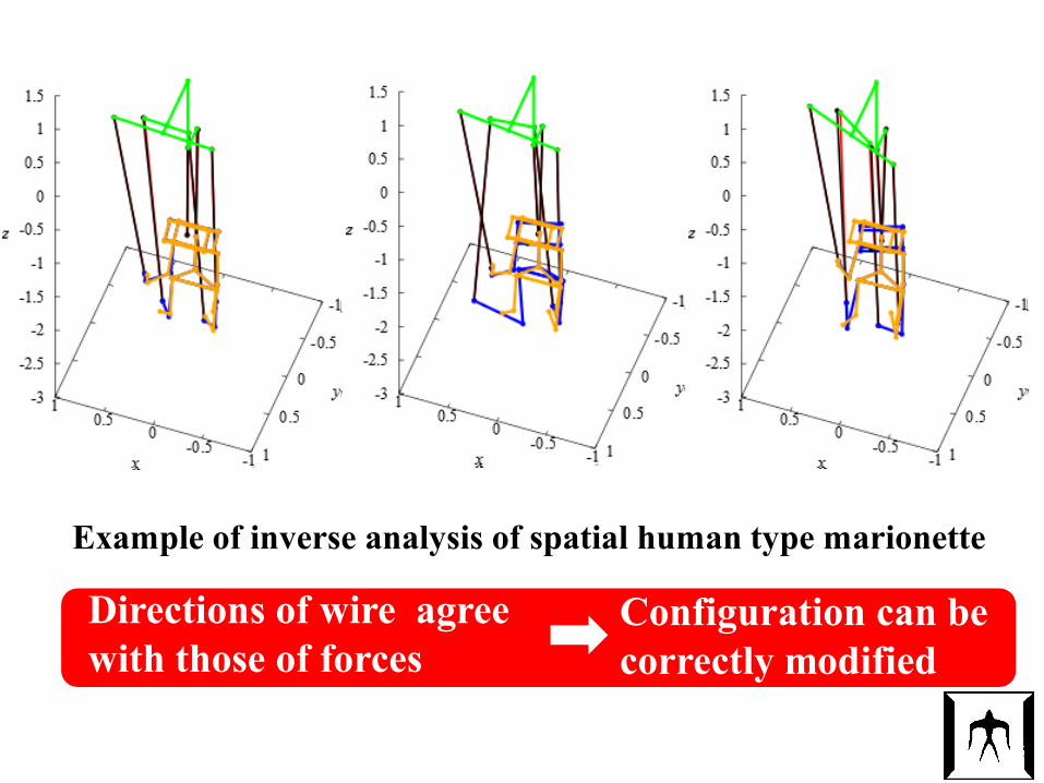
Example of inverse analysis of spatial human type marionette
Configuration can be correctly modified
Directions of wire agree with those of forces
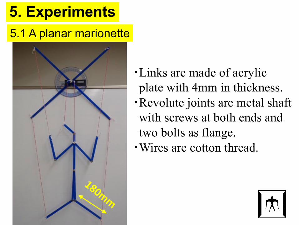
5. Experiments5.1 A planar marionette
・Links are made of acrylic plate with 4mm in thickness.・Revolute joints are metal shaftwith screws at both ends andtwo bolts as flange.・Wires are cotton thread.
27
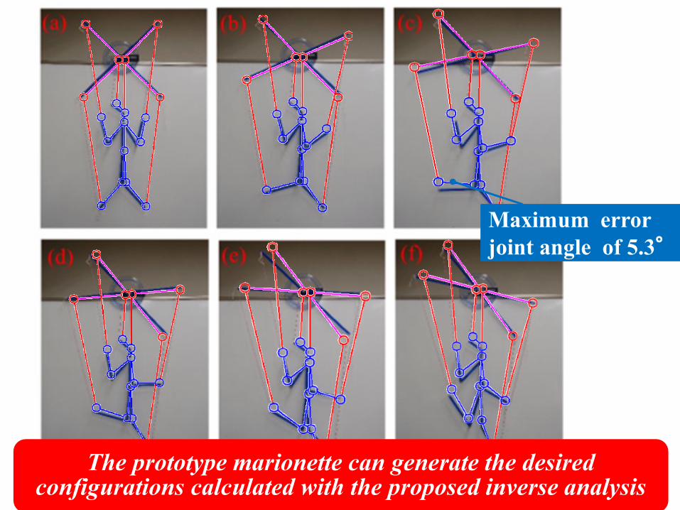
Maximum errorjoint angle of 5.3°
The prototype marionette can generate the desired configurations calculated with the proposed inverse analysis
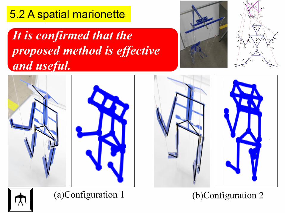
(a)Configuration 1 (b)Configuration 2
It is confirmed that the proposed method is effective and useful.
5.2 A spatial marionette
6. Concluding remarks
Aiming to establish the general method to controlunderactuated wire-driven mechanisms, kinetostaicsanalyses are proposed and examined.(1)The configuration of link chain hung with several wires
can be calculated with the optimization to minimize thevertical position of center of gravity of the chain.
(2)The configuration of controller can be calculated withwire directions based on the inverse analysis and theoptimization of the modifying angles of link chains.
(3)Motion planning of planar and spatial human typemarionettes can be achieved with the proposed inversekinetostatics.
(4)The proposed method was experimentally validatedwith prototypes of the human type marionettescomposed of links of acrylic bars and cotton threads.
Concluding remarks for whole lectureThrough this lecture, you are expected to be able to:(1) Explain mobility of mechanism and relation between
input/output motion of mechanism(2) Analyze displacement, velocity and acceleration of
planar/spatial closed-loop link mechanism with the systematic kinematic analysis method
(3) Analyze the dynamics of planar/spatial closed-loop link mechanism utilizing the systematic kinematic analysis method
(4) Explain the optimum motion control of redundant link mechanisms
(5) Explain motion control of underactuatedmechanism with elastic elements
Important issues explained in this lecture are as follows:
(1)Kinematic analyses of planar/spatial link mechanism with the systematic kinematic analysis method
“Displacement, velocity and acceleration analyses of planar/spatial closed-loop link mechanism can be easilyachieved.”
(2)Dynamic analyses of planar/spatial link mechanism “Driving forces and joint forces can be analyzed using the systematic kinematic analysis.”
(3)Optimum motion control of redundant link mechanisms“Dexterity can be maximized by utilizing redundancy.”
(4)Motion control of underactuated link mechanisms“Underactuated mechanisms constrained with elastic
elements can be controlled by taking account of kinematics and statics.”
(5)Motion control of wire-driven underactuated link mechanisims
“Marionette can be theoretically controlled.”
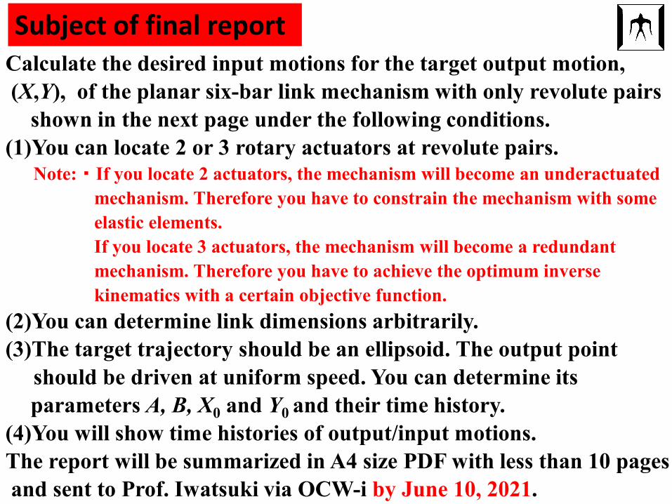
Subject of final report Calculate the desired input motions for the target output motion, (X,Y), of the planar six-bar link mechanism with only revolute pairs
shown in the next page under the following conditions.(1)You can locate 2 or 3 rotary actuators at revolute pairs.
Note: ・ If you locate 2 actuators, the mechanism will become an underactuatedmechanism. Therefore you have to constrain the mechanism with some elastic elements.If you locate 3 actuators, the mechanism will become a redundant mechanism. Therefore you have to achieve the optimum inverse kinematics with a certain objective function.
(2)You can determine link dimensions arbitrarily.(3)The target trajectory should be an ellipsoid. The output point
should be driven at uniform speed. You can determine its parameters A, B, X0 and Y0 and their time history.
(4)You will show time histories of output/input motions.The report will be summarized in A4 size PDF with less than 10 pagesand sent to Prof. Iwatsuki via OCW-i by June 10, 2021.
O
Y
X
R
R
R
RR
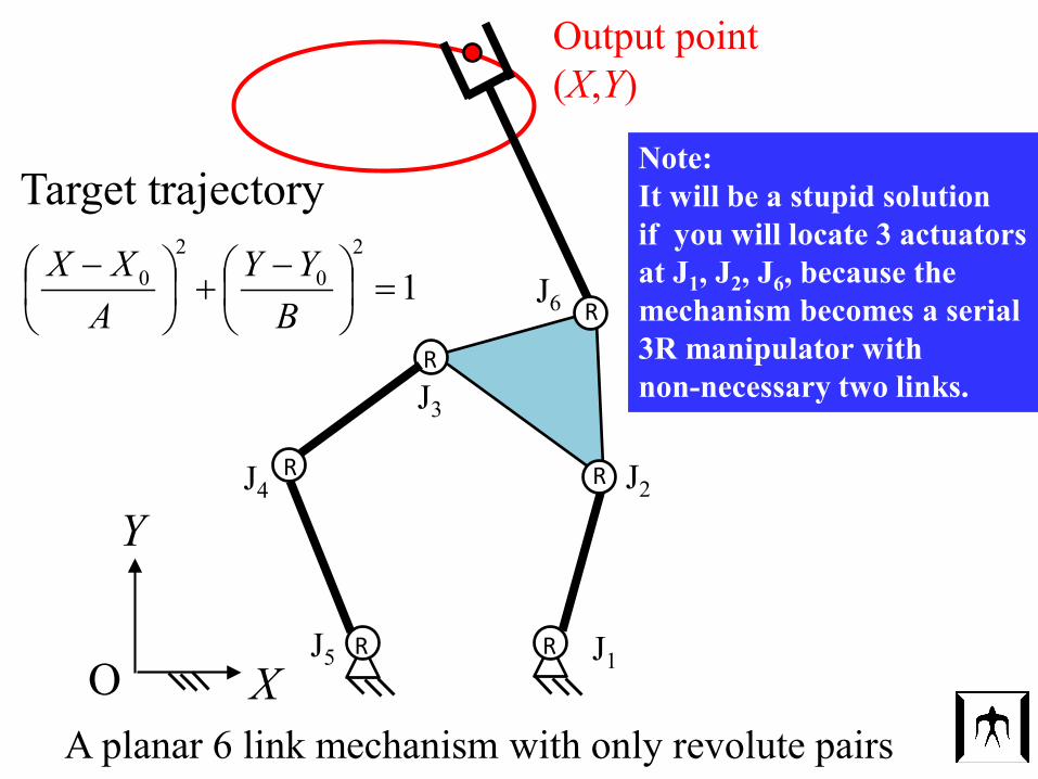
A planar 6 link mechanism with only revolute pairs
Target trajectory
Output point(X,Y)
12
02
0 =
−
+
−
BYY
AXX
RJ6
J1
J2
J3
J4
J5
Note:It will be a stupid solutionif you will locate 3 actuatorsat J1, J2, J6, because the mechanism becomes a serial 3R manipulator with non-necessary two links.