may – june 2007 - the mmt · pdf filedusty clark began writing the firmware for the...
TRANSCRIPT
MMT Observatory • The University of Arizona • Tucson, Arizona 85721 • PHONE: 520. 621. 1558 • FAX: 520. 670. 5740
S m i t h s o n i a n A s t r o p h y s i c a l O b s e r v a t o r y & S t e w a r d O b s e r v a t o r y , T h e U n i v e r s i t y o f A r i z o n a
BIMONTHLY SUMMARY
May – June 2007
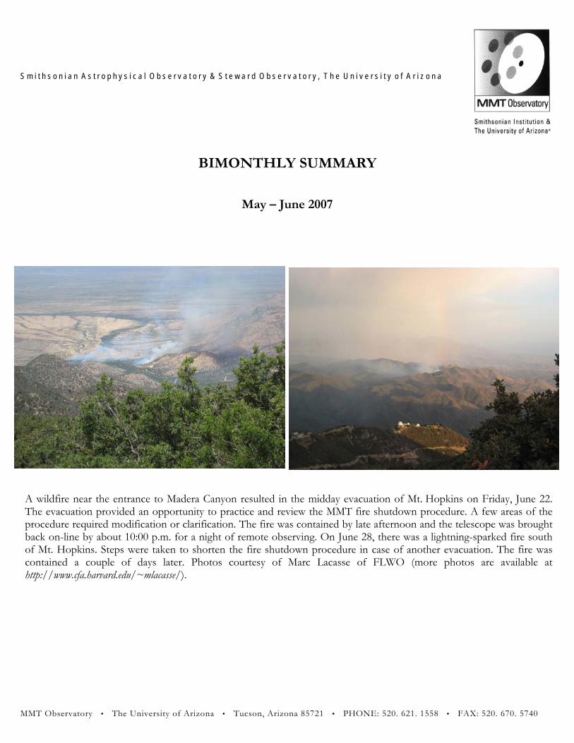
A wildfire near the entrance to Madera Canyon resulted in the midday evacuation of Mt. Hopkins on Friday, June 22. The evacuation provided an opportunity to practice and review the MMT fire shutdown procedure. A few areas of the procedure required modification or clarification. The fire was contained by late afternoon and the telescope was brought back on-line by about 10:00 p.m. for a night of remote observing. On June 28, there was a lightning-sparked fire south of Mt. Hopkins. Steps were taken to shorten the fire shutdown procedure in case of another evacuation. The fire was contained a couple of days later. Photos courtesy of Marc Lacasse of FLWO (more photos are available athttp://www.cfa.harvard.edu/~mlacasse/).

Personnel On May 17, Faith Vilas gave a talk, entitled “The Japanese Hayabusa Mission to Asteroid 25143 Itokawa,” to the Sun City Vistoso Astronomy Club. In late May Skip Schaller moved back to Chile; however, he is still employed by MMTO and telecommutes. Grant Williams attended the “Hot Wiring the Transient Universe” conference at the College of Optical Sciences, the University of Arizona, the week of June 4-8. Summer intern student Mia Romano was hired in early June to assist Dan Brocious (FLWO) with light pollution issues. On June 7, Tom Gerl and Ricardo Ortiz attended safety training at the Steward Mirror Lab (SOML) for working in confined spaces. John Glaspey left the MMTO June 30. Dennis Smith assumed the position of Mountain Operations Manager (Acting) upon John’s departure. Grant Williams was appointed to the AAS Committee on Light Pollution, Radio Interference and Space Debris.
Primary Mirror Systems Primary Mirror Support Due to the continued unavailability of the SOML portable vacuum curing chamber, which is needed for degassing the RTV mixture used for puck bonding, MMTO is constructing its own with considerable help from J. T. Williams, Jill Cooper, and others. When this equipment is completed, we expect to begin doing the long-deferred puck bond degradation testing of primary mirror supports based on the accelerometer response we have reported on previously. Problems occurred with actuator #49, which is a unique actuator because it is in a location that requires removal of the entire actuator in order to test its electronics card. The card was changed out but the problems, which only showed up during operation, remained. The unit was rebuilt with different Bellofram control valves. That solved the problem. Optics Several years of MMTO mirror (and reference standards) coating reflectivity and scattering measurements from the Minolta CM-2002 Spectrophotometer were compiled into a single new MySQL database. Data, documentation, and software have been consolidated on the MMTO “Vault” Windows computer. Data have been re-analyzed, using more consistent standards and analysis techniques. Graphs have been prepared to illustrate aluminum coating degradation with time and systematic variation in instrument measurements. Much effort was made in verifying the quality of data and of correction factors.
2

In addition, step-by-step checklists and procedures have been started on the MMTO DokuWiki. A series of photographs was taken to illustrate various aspects of instrument calibration, reflectivity and scattering measurement, and data reduction using the SpectraQC software. Work continues on data acquisition and analysis as well as documentation. The primary mirror was CO2 cleaned, and reflectance and scattering measurements taken, on May 2, May 23, and June 21. Thermal System The heretofore shelved work on the T-series thermocouple electronics was dusted off, and more progress was made in getting this system built. Layout of both the differential and absolute temperature measurement boards was completed, and we moved on to construction of the “motherboard” for the two that will handle the data flow from the conversion electronics and make them available on the network. We solved the primary difficulty of how to package the boards into the system by adopting brackets from the PC motherboard industry, and designing the system to accept the boards with this mechanical attachment. Brian Comisso located some Euro style connectors that considerably improved mechanical and electrical performance. The board layouts were modified accordingly. Dusty Clark began writing the firmware for the system, using the UCOS-II real-time kernel to provide the different data collection, calculation, and networking tasks to service the thermocouple readouts. We expect to send the boards out for fabrication this summer. M1 Thermal System Performance and Control We found that while the “carrier_auto” service that we developed worked well under stable conditions, it didn’t cope well with rapid changes in ambient temperature. We experimented with different algorithms for determining the appropriate Carrier chiller setpoint, but they also proved to be insufficient. Although part of the problem was the large heat load from the f/5 wavefront sensor (WFS) system and instruments, we decided to disable this service until we could do a more thorough, quantitative analysis of M1 thermal system performance. This analysis was done by comparing the past year of Carrier setpoint values with other parameters, such as ambient temperature and M1 isothermality. Analysis of the E-series thermocouple data measuring M1 glass and lower plenum air temperatures produced some interesting results. We found a strong correlation between the root mean square (RMS) variation in air temperatures in the lower plenum and RMS variation of M1 glass temperatures (see Figure 1). The minimum RMS values are obtained when the Carrier setpoint is offset about -7 C from the chamber ambient temperature. This is very close to the -6.5 C we had previously determined from looking qualitatively at a few nights’ worth of data. While there is a lot of scatter, the lower bound of the RMS values clearly trends upward as the setpoint offset is either increased or decreased from -7. There is also a correlation between radial temperature gradients in the mirror cell lower plenum and in M1. The implication is that the air in the lower plenum warmer center is not being well mixed before it is injected into the mirror. The primary mirror cannot be cooled completely isotropically.
3

This impacts our ability to adjust to variations in ambient temperature, or to target a temperature very different than the current mean glass temperature. Analysis of these results is ongoing, and methods of improving overall thermal system performance, and how to mitigate the effects operationally, are being investigated.
Figure 1: Logged thermal system data showing the correlation between temperature variations within the lower plenum and temperature variations within the M1 glass. The data have been clipped at an M1 RMS value of 0.35C.
Secondary Mirror Systems f/9 Secondary Brian Comisso solved issues with the tape limit switch on the secondaries. We added a de-bounce circuit and some power-up reset functions to try to eliminate some of the false triggering. f/5 Secondary Support Jill Cooper gathered all information on the “iron maiden” trunnion test fixture, and is in the process of modeling the structure to determine its load capability. (All data on the structure were apparently lost in a hard drive crash long ago.) The current plan is to use the existing structure as a fixture to test and align the f/5 secondary support system operation at all elevation angles. The current “iron maiden” has an inadequate rotational control system. Marc Lacasse (FLWO) has a hand gear drive
4
assembly that is under consideration as a possible alternative. If used, additional design and modeling will be needed to ensure the system can rotate the f/5 mirror assembly safely. J. T. Williams is providing mechanical/technical support.
Telescope Tracking and Pointing Mount Servos Work continues on the servos. The new VxWorks elevation servo now capably slews the telescope. Tracking performance, however, is poor and does not match what is expected from simulation, nor what is obtained running the servo via the xPC Target machine. Recent work focused on pinpointing the difference between the same controller running under VxWorks and xPC Target. A number of experiments were performed to validate the code generation process and the VxWorks runtime environment. Since the controller is in fact a digital filter, it can be run open loop with a known input stimulus. This was done using the MATLAB native simulation and with the model running on a VxWorks x86 machine serving as a mount simulator. The results obtained were identical, and led us to look at other differences between the xPC Target system used for prototyping and the final runtime system. A crucial difference, which we have not thoroughly considered until now, is that the two systems use different IO hardware. The xPC Target system used an IP-Quadrature board for encoder input, and an Acromag IP-230 DAC for motor command output. The VxWorks system uses an LM628 as an encoder input counter and a PCI DAC card from Measurement Computing for motor command output. The VxWorks system was modified to use the IP-Quadrature for encoder input. We were especially suspicious of the LM628, as we had benchmarked over 100 microsecond latencies in accomplishing an encoder read (whereas the IP-Quadrature can deliver a counter value in less that 20 microseconds). However, when we made this change we found that there was no change in performance. The latencies of the LM628, while disturbing, are adequate to run our servo loop at 1000 Hz. (A simulation by Dusty Clark is available at:
http://www.mmto.org/~dclark/Reports/Delays%20in%20the%20MMT%20Elevation%20Controller%20in%20Simulation.pdf and shows that delays of up to several milliseconds in the servo feedback path can be tolerated.) Present work is focusing on the DAC subsystem. We will next concentrate on discovering what other subtle difference in software/hardware led to such different tracking performance between the xPC Target test system and the VxWorks deployment version. New tests will use the PCI DAC6703 from Measurement Computing in both the xPC Target and the VxWorks system. We intend to run the two models on the same computer with exactly the same IO hardware and signal paths and see what can be learned from that. MMT Pointing Performance The results of the pointing testing we conducted in March 2007 didn’t appreciably improve our pointing performance. Implementing a higher order pointing model would have helped, but would
5

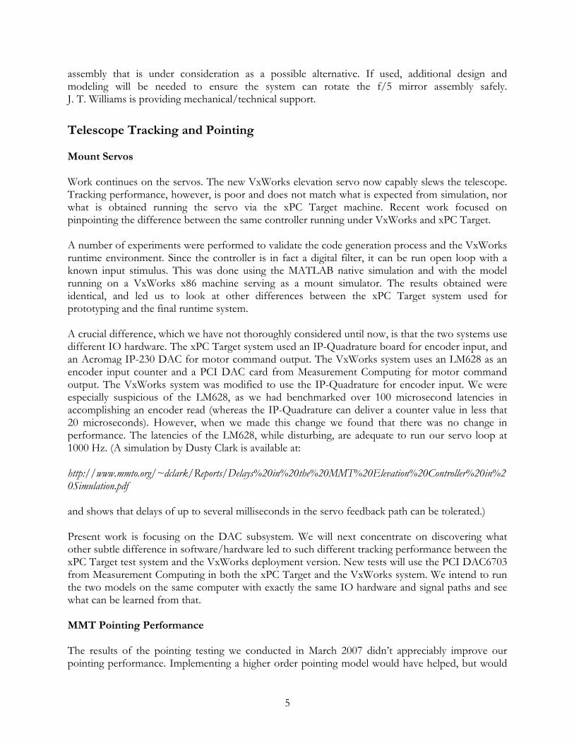
have required a significant amount of mount software work. Before embarking on such an endeavor, we wanted to check our results using a larger pointing run with better azimuth coverage. We did this on the night of May 30, where we compiled pointing data from 156 stars. The best-fit results using a standard TPOINT alt-az model are: IA = 1191.16 1.29 IE = -1.81 0.30 NPAE = -4.23 1.53 CA = 16.71 1.88 AN = -1.32 0.10 AW = -13.25 0.10 TF = 7.65 0.89 TX = -2.80 0.29 Sky RMS = 1.15 Popn SD = 1.18 This is a significantly better fit than we obtained with the same model fit to the March data. However, adding the harmonic terms that improved the fit to the March data does not make an appreciable improvement when applied to the new data. Figure 2 shows the coverage of this run, and the residual errors of predicted position versus measured as a function of elevation and azimuth. Figure 3 shows the radial alt-az residuals. Figure 4 shows six different residual plots, and Figure 5 shows a plot of the hysteresis in the pointing data. TPOINT calculates the hysteresis to be 0.63 arcsec at an orientation of -36 degrees. This explains the elongation in the residual distribution shown in Figure 3 and is a significant component of the overall RMS pointing error. It is likely due to hysteresis in positioning M2 since we are applying our standard open loop corrections to M2 after every slew. The TF term in the fit is the residual tube flexure not corrected by our M2 open loop model. It corresponds to 7.65 arcsec of elevation pointing error between zenith and horizon, which is about an order of magnitude smaller than the corrections our model is making. This residual misalignment can affect off-axis performance with the wide-field corrector. However, the image quality modeling presented in the MMT Conversion documents suggests that the effects should be fairly slight for this level of misalignment. In the future, we will experiment with setting the TF and TX terms to zero before taking data to calibrate the M2 open loop models. This will help ensure that all of our tube and front-end flexure effects are corrected by repositioning M2 rather than the mount. Since we have implemented these results into the mount, our pointing has improved noticeably. The systematic azimuth-dependent errors we were seeing before are no longer noticeable. The pointing residuals, as measured by the WFS when it recenters, have decreased by almost a factor of three with the new pointing model.
6

Figure 2: This shows the distribution of stars observed in the May 30, 2007, pointing run as a function of elevation and azimuth. The arrows denote the residual error between the predicted model and actual reported positions. The magnitude of a 1" error is shown by the labeled arrow in the upper right corner of the plot.
7
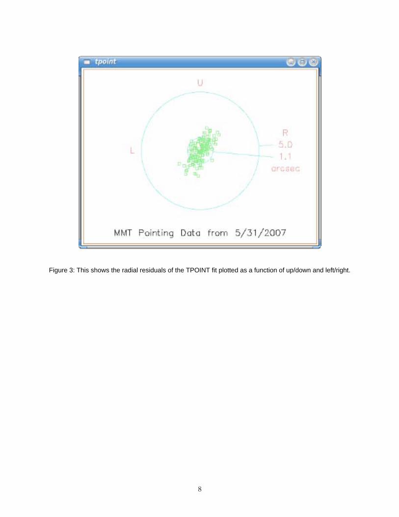
Figure 3: This shows the radial residuals of the TPOINT fit plotted as a function of up/down and left/right.
8

Figure 4: Plots of different projections of TPOINT fit residuals. • Upper Left: Azimuth residuals vs. Azimuth • Upper Middle: Elevation residuals vs. Azimuth • Upper Right: Az/El nonperpendicularity residuals vs. Azimuth • Lower Left: Azimuth residuals vs. Elevation • Middle Left :Elevation residuals vs. Elevation • Lower Right: Pointing residuals interpreted as a misalignment of the azimuth axis. The
histogram consists of the orientations calculated for each observation. The points show the component of the pointing residual for each observation in the direction of the mean orientation.
9
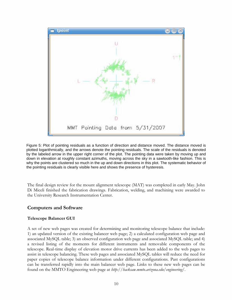
Figure 5: Plot of pointing residuals as a function of direction and distance moved. The distance moved is plotted logarithmically, and the arrows denote the pointing residuals. The scale of the residuals is denoted by the labeled arrow in the upper right corner of the plot. The pointing data were taken by moving up and down in elevation at roughly constant azimuths, moving across the sky in a sawtooth-like fashion. This is why the points are clustered so much in the up and down directions in this plot. The systematic behavior of the pointing residuals is clearly visible here and shows the presence of hysteresis.
The final design review for the mount alignment telescope (MAT) was completed in early May. John Di Miceli finished the fabrication drawings. Fabrication, welding, and machining were awarded to the University Research Instrumentation Center.
Computers and Software Telescope Balancer GUI A set of new web pages was created for determining and monitoring telescope balance that include: 1) an updated version of the existing balancer web page; 2) a calculated configuration web page and associated MySQL table; 3) an observed configuration web page and associated MySQL table; and 4) a revised listing of the moments for different instruments and removable components of the telescope. Real-time display of elevation motor drive currents has been added to the web pages to assist in telescope balancing. These web pages and associated MySQL tables will reduce the need for paper copies of telescope balance information under different configurations. Past configurations can be transferred rapidly into the main balancer web page. Links to these new web pages can be found on the MMTO Engineering web page at http://hacksaw.mmto.arizona.edu/engineering/.
10
Linux OS Updates Our last two Fedora Core 5 machines, yggdrasil and hoseclamp, were updated to Fedora Core 6. This went smoothly except for a long-known, but as yet unfixed, bug in certain Tk implementations (including perl-Tk) where text input widgets refuse to work when using the default input manager. This severely affected the scope and alt-az GUIs, specifically. The workaround is to configure the systems to use the legacy X windows input manager. This appears to have no other noticeable ill effects, so will be part of our default system configuration. We have started to look into Fedora Core 7. So far, no glaring incompatibilities have been found, at least not in addition to those already found in previous releases. Care will have to be taken when performing upgrades since Fedora Core 7 has completely revamped handling of IDE devices, which causes their device names to change.
Instruments f/15 Instrumentation Under the supervision of Thomas Stalcup, we recabled and adjusted the AO rack on the third floor to dress the cabling and provide better access. All of the equipment that had been on the floor is now in the rack. The rack electronics were documented, and most of the cables were labeled. The CCD controller and power supply were mounted inside an electronics enclosure on the AO topbox. This eliminated the temporary installation that used cargo straps. The cables still need to be terminated at the proper length. Design for a strain relief bracket for the WFS camera is in progress. Natural Guide Star (NGS) The f/15 run in late June got off to a rocky start, with gap contamination at the beginning of the first night. Thomas Stalcup and Phil Hinz (Steward) were able to work it down to a level that allowed the run to continue, but after the run the shell needs to be removed and cleaned. This work will be done primarily by CAAO staff, but a few interested parties from MMTO may be present as well. This run was the first that had AO operators from the MMT staff present for the entire time. Creighton Chute started out the run, and Morag Hastie took the second half. By the end of their respective times, Creighton and Morag were operating with minimal assistance. Another milestone reached was the successful mating of the f/15 secondary with the test stand, and obtaining interferometer images of the surface shape. Some problems were found with the adjustments used to align the mirror to the test stand, and improvements are planned for the future. The alignment needs to be improved before the measurement quality is high enough to start actuator calibrations, but this should only take a few days. Laser Guide Star (LGS) The test stand was modified by adding an optical breadboard area to allow directing some of the return light from the mirror to the LGS wavefront sensor. The breadboard was designed by
11

Creighton Chute and installed by Creighton and Bill Stangret. The optical design was produced and implemented by Thomas Stalcup. Using the LGS wavefront sensor on the test stand, the laser AO correction loop was successfully closed up to Zernike order 8. This was a big step forward in preparation for the next attempt at closing the LGS loop on the sky. MIRAC/BLINC Some time was spent supporting the operation of the He compressor for MIRAC, which had problems with high ambient air temperature. Apparently it will be replaced with a liquid-cooled unit in the future. f/9 Instrumentation Blue Channel and Red Channel Spectrographs On the engineering nights of June 23-24, additional throughput data were obtained for the Red and Blue Channel spectrographs. We now have throughput data for the new Red Channel detector using all the available grating configurations with the exception of the echellette mode. Reduction of the data is not yet complete, but we anticipate that an online exposure time calculator will (finally) be available for use in the first trimester 2008 proposals. The procedure for swapping from the Blue Channel to the Red Channel spectrograph has been added to the MMT dokuwiki. The Steward machine shop continued to work on the new short slit plates for the Red Channel echellette mode. A new diamond tip was acquired to cut the flat reflective surface of the plates; the previous tip had sustained damage from the steel plugs in the slit plates. Efforts to produce a smooth surface with the damaged tip resulted in a poor surface that was unusable. The new tip provided much better results. All plates have now been machined and inspected under a microscope, and will be ready for use following a cleaning. SCCS/ICE Updates The new SCCS server and GUIs were deployed and used during Red Channel engineering on June 23-24. There were a few quirks, but overall things worked well. We will continue to use them as-is for the July 2007 Blue/Red channel time, which will largely be used by MMTO staff (Faith Vilas, Grant Williams). During summer shutdown, we will refine and finalize the interfaces and update the appropriate documentation. Some changes and enhancements were made to ICE to prepare for supporting the CCD camera in MAESTRO. An IRAF script was written and integrated into our ccdacq environment that will automate the acquisition of a set of spectrograph focus exposures. The observer is still required to analyze the images using, e.g., specfocus, but we hope to integrate that step into our script. This will require some engineering data to assess various failure modes and tune specfocus parameters. It will also require some effort to support echellette mode as well as long-slit.
12

f/9 Top Box Switches on the f/9 topbox paddle began malfunctioning. Investigation of the problem confirmed that the switches had a high resistance when closed. These were swapped with some of the unused switches in other circuits. It was apparent that this had been done in the past, and probably will not be feasible again. The next repair of this nature will be much more difficult, but it could be accomplished with the conversion to operation via GUI.
f/5 Instrumentation Hectospec The atmospheric dispersion compensator (ADC) had some new troubles during this reporting period. On May 9, Perry Berlind (FLWO) noticed that the east prism of the ADC was not tracking properly at low elevations. A couple of nights later the prism stuck a few degrees from the target position. Maureen Conroy (SAO) found that there were problems with the east prism’s tracking prior to May 9. The ADC worked acceptably through the end of the run. Suspicions for the cause of the problem included cables, connectors, drive circuitry, bearing problems, and gear problems. The electrical path to the motor was ohmed out by Ken Van Horn on May 14 and found to be good (2.8 or 2.9 ohms through cables and windings). Marc Lacasse inspected the system next and found no visible problems, though there was a mechanical binding sensed when turning the spur gear and later, after the spur gear was removed, in turning the prism’s ring gear. Bob Fata, Joe Zajac and Kevin Bennett (SAO) arrived on June 8 to work on the ADC. The force to turn the gear was variable 9-20 pounds when the prism was horizontal, and got as high as 30 pounds when the ADC unit was tipped. The motor was also tested and found to deliver 50 pounds of force at the edge of its gear. Bob Fata remembered a lower force to turn the gear, but the safety factor was insufficient with the current conditions. On June 9 the ADC was carefully disassembled with the fixtures shipped from Cambridge, Massachusetts. The two bearings were lightly greased and the six optical surfaces cleaned. The ADC was reassembled, and we found that the force required to turn the prism went down a factor of three to about 8 pounds and was very uniform. A couple of wires damaged during disassembly were repaired, and the unit was successfully tested that evening. Pictures of the process are available at http://www.cfa.harvard.edu/~mlacasse/Photos/. MAESTRO The last two months has seen MAESTRO take giant leaps towards being ready for the first commissioning period at the end of July just before summer shutdown. The instrument team has successfully installed and aligned the camera barrel, input optics, and calibration lamps. The prism, grating, and CCD dewar will be installed in early July. The main focus translation stage attached to the first lens in the camera barrel, and the translation stage for the slit viewing camera, were exercised on the bench before being installed and having rough limits determined.
13
The mountain staff has done an extensive job in preparing for the arrival of MAESTRO; the pit has been comprehensively cleared out and services have been organized. There is now room for the instrument to be stored in the pit, and Ethernet and clean AC power are available on the loading dock. They will soon be available in the pit. A second Ethernet connection will be added in each location. Todd Jackson, under the supervision of Shawn Callahan, has been assisting with the design of the instrument covers. Thomas Stalcup has advised on techniques for internal optical alignment of MAESTRO, and was able to supply equipment that made the procedure much more robust. Many MMT staff have been involved in devising the most appropriate way of transporting MAESTRO from Tucson to the summit, and mounting the instrument on the telescope. Morag Hastie, Tim Pickering, Grant Williams, and Betty Stobie met with the MAESTRO team to discuss computer support and software needs during the July commissioning run. f/5 Wavefront Sensor The f/5 WFS system was rather problematic during most of the time it was on the telescope from late April through early June. All of the various problems boiled down to two root causes: 1) The power and USB cables feeding the WFS’s SBIG CCD camera were loose, and the power cable eventually disconnected completely; 2) The cooling fan for the CPU in the WFS’s on-board computer failed completely. This caused the CPU to overheat and probably not work reliably. Once these problems were discovered and fixed, the f/5 WFS worked without any issues for the remainder of the f/5 run. In the course of investigating these problems, we determined that the servo amplifiers within the WFS generate significant heat. Servo power should thus be kept off except when motion is required. We will implement automation of this over the summer. We also discovered that shutting down the WFS computer from the windows “Start” menu ironically results in a corrupted network disk image. Simply killing power to the WFS computer appears to have no ill effects after many repeated attempts, which greatly simplifies the process. A warm air scavenger was reconnected to extract excess heat from the central cone.
Documentation With assistance from Dallan Porter, Cory Knop converted five training VHS videotapes to DVD and loaded them into the computer based training server. Cory contacted Sylvia Kendra at the Smithsonian Institution, and they have agreed to copy our drawings to digital .pdf format and provide us with a DVD of the drawings. They will keep the drawings and archive them for us, but we will have access to the physical copies if ever required. We are responsible for providing the proper shipping containers and for shipping costs to Smithsonian. They will pay the shipping costs of the DVDs. Cory is currently working with Steve Criswell (FLWO) to determine how shipping costs will be handled.
14

The following documents were scanned and added to SiteScape: 1) all H-Files; 2) miscellaneous schematics; 3) TIW 6.5-m Conversion documents; and 4) Simpson Gumpertz & Heger Inc. 6.5-m Conversion documents. In addition, Cory provided Dallan with a list of all photos that must be unzipped and thumbnailed, is inventorying the schematics to be sent to Smithsonian for archiving, and removed all ORCAD drawings from SiteScape and placed them in the electronics drive on the vault under completed project (the .pdf drawing files were left on SiteScape). Cory produced an informative MMTO brochure, copies of which are available in the department office on campus as well as at the telescope. Observers are encouraged to peruse them prior to an observing run at the MMT.
LOTIS Aluminizing Project Activity during the reporting period focused on staging all the welders and related electronic equipment for coating. A new set of 3/0 cables were constructed for connection of the welders to the vacuum chamber feedthroughs. Each of the new cables was tested under load to detect any bad connections or other I-R drop issues — all passed. While unpacking the welder control electronics, we also verified that all the spares and documentation were up to the current revision. It turned out that there was a minor component change on the spare, and this was corrected. Each welder was individually powered and tested, and then all the units were tested together on the still-loaded filament set that was in the vacuum chamber during the last coating. The short-time arcing experienced between the copper feedthrough and the chamber wall, due to water contamination, appears to have been solved thanks to careful disassembly, cleaning, and re-painting the vacuum chamber feedthrough section. Three full-power test firings and witness plates were completed in May by MMTO. Based on test data, changes to the vacuum backing lines and electrical controls were implemented in June. The type, size, and number of witness slides and test plates were decided by the project in late May. LOTIS purchased additional plate glass for a variety of adhesion, contamination, suction-cup lift-test on aluminum coat, and ultimate adhesion/peel coat testing. Materials and representative glass plates were delivered in June, and are now being final cleaned for mounting in the vacuum chamber. This work is taking place while the chamber is open for replacement of filaments. Much of the chamber preparation work with glass slides, plates, new filaments, and thickness monitors will be performed during pre-dawn work shifts. Pump-down and leak checking of the “loaded” chamber will be underway during the last week of July.
General Facility Light Pollution On June 19 several of the FLWO staff, along with Mia Romano and Grant Williams from the MMTO, met with representatives from the Tucson Sector of the Border Patrol to discuss our
15

concerns about light and radio emissions from the planned permanent Border Patrol checkpoints. The meeting went well; the Border Patrol agents were receptive to the concerns of the astronomy community, and presented us with a letter from the Chief Agent for the Tucson Sector expressing the wish to learn what the potential impacts might be and how they could be mitigated. The lighting design for the new checkpoints was discussed, and we suggested that the Pima County Outdoor Lighting Code be used as a guideline. In addition, we established a means to prevent over-flights from Border Patrol helicopters equipped with bright search lights. The Border Patrol requested that we follow-up with a letter that includes questions they were unable to answer at the time of the meeting. The Border Patrol plans outreach efforts in Sierra Vista and Ajo regarding check points and new enforcement technologies. Facility Repair Projects The Smithsonian Office of Facilities Engineering and Operations (OFEO), MMT engineering, and M3 Engineering are currently working together on three projects: 1) chamber floor replacement; 2) MMT roof repair; 3) and instrument repair facility. Chamber Floor Replacement The chamber floor replacement was given highest priority, with the goal to demolish the existing floor during summer shutdown. The floor package was designed by M3 Engineering, with design input from the MMT staff and Smithsonian. All work on removal of the light lock was eliminated from the design package. The light lock will be removed by MMTO staff before the new floor is installed. The final design package was approved by Smithsonian in early June and then delivered to contractors for bids. The floor replacement documents are in SiteScape. MMT Roof Repair A thermoplastic roof was selected for the repair of the MMT roof. M3 Engineering prepared the design documents with input from MMT staff and Smithsonian. The owner of Rain-Tite Roofing and an engineer from Duro-Last, a thermoplastic roofing manufacturer, inspected the roof to determine how best to design the installation to survive the 148 mph measured wind speeds. New roof heaters will be installed, and all damaged elastomer seals will be replaced. The roofing package was approved by Smithsonian on June 15.
16

Instrument Repair Facility
Figure 6: This picture shows Ron Olsen (Rain-Tite Roofing) measuring the pull-strength of typical fasteners used to attach the new roofing material. The pull strength of each fastener was typically 500 lbs. This is more than adequate to meet our extreme wind loads. Photo by Shawn Callahan (MMTO).
Development of the new instrument repair facility, which was placed on hold during the development of the floor replacement and roof repair, was restarted in mid June. Using design input from MMT engineering, the facility was redesigned to bring the project within our budget. In an effort to reduce costs, M3 Engineering is investigating replacement of the retaining wall with a post and beam foundation. To advance this design, they first need to determine the make-up of the rock and soil, which requires site testing the rock by core drilling.
Figure 7: Future site of instrument repair facility. Photo by Shawn Callahan (MMTO).
17
Higher resolution images of the site can be downloaded at: http://www.mmto.org/~callahan/Smithsonian%20projects/Instrument%20repair%20facility/instrument%20repair%20images/. Building Drive The building drive system began exhibiting intermittent collisions and episodes of “washing-machine mode.” Dusty Clark and Dondi Gerber went to the site to troubleshoot. After checking the standard problem areas such as stuck LVDTs (Linear Variable Differential Transducer) and bad relays, the analog servo control card in the building drive was swapped with the spare. Tom Gerl subsequently inspected the suspect card and discovered a resistor with only one of two leads soldered onto the board. We suspect that the board worked for a long time by virtue of the copper and the component lead touching, and years of oxidation made the connection intermittently bad. Touching up the solder joint with actual solder appears to have solved the problem, and the building drive has had no more collisions as of this writing. Weather and Environmental Monitoring The Yankee MET-2010 thermohygrometer is still out for repair/calibration. The company discovered that the system does not operate to specifications in low humidity conditions. This problem appears to be systematic and is a possible design/software problem, not a problem unique to our unit. No estimate of when our unit would be ready was available. Work started on the installation of a Vaisala WXT-510 weather station on the west side of the MMT building. The current plan is to mount the station near the R. M. Young wind vane. The electronics will be mounted in the metal enclosures at the bottom of the weather pole. A wireless Lantronix will be used for communication to the network. If this has any problems, we will run fiber to the location via the underground pipes. Power is already available at the location. The old Vaisala has been reprogrammed completely and seems to be working again. Other Facility Improvements and Repairs Preventive maintenance, including a thorough battery test, was done on the MGE UPS by the factory representative. The unit appears to be in good condition, and we learned that its internal temperature upper limit is 33 degrees C. An internal register, which had been set at the factory to indicate the batteries might need replacement after four years, was reset for another four years. Dennis Smith replaced the cable sleeves and lubricated the guides on the JLG personnel lift. The lift, which was binding when lowering, now operates much more smoothly. He also replaced the pillow blocks bearings on the trench fan, which runs continuously and helps remove heat from the pit. Bill Stangret and Dennis Smith did a complete preventive maintenance and cleaned the condenser on the Gardner-Denver air compressor. The compressor now runs approximately 10 degrees cooler. While making storage room for MAESTRO in the pit, Bill Stangret and Dennis Smith have been housecleaning some items to surplus and some others to the dumpster. As part of the pit clean up,
18
Tom Gerl sorted and inventoried many of the electrical parts. The pit cleanup spawned significant cleanup of the fourth floor loft in order to accommodate moving some wire storage from the pit to the loft. Most of the excess wire has been surplused to the basecamp or thrown out. A vacuum cleaner was actually used on the carpeting. Bill Stangret fabricated two brackets to center the “pig” hitch attachments for the Megacam cart. The attach points were formerly off-center and C-clamped on. The new arrangement is bolted on and eliminates the need for C-clamps. Removal of a seldom used vacuum pump from the cart opened space for the new hitches. The blower control module was completed and bench tested, but won’t be installed until a minor software update is made. Once the update occurs, the control should function with either the old or new module. In order to gain access to troubleshoot a perceived problem with the elevation stow pin, major adjustments were made to the cable drape. The problem turned out to be an issue with the way the stow pin works with the elevation by-pass, which encouraged us to document stow pin operation. The elevator lights were modified to support the removal of the light lock on the second floor. There still are lamps to be replaced with red LEDs in the floor call buttons. These are on order by UA Facilities Management. The safety committee was unhappy with the access to the trench for draining the air lines therein. Tom Gerl procured and installed two electrically operated valves, negating the need for a human to go into the trench for that task. Tom also worked on the chamber monitor camera. He also again helped repair the toilet after someone put a paper towel in it. The cabling has been completed for the transverse counterweights. This system should be functional as soon as software is available.
Visitors June 13: Dan Brocious (FLWO) accompanied a crew from local TV station KOLD-TV 13 to tape a segment for a series of live broadcasts from various southern Arizona observatories. June 14: Dan Brocious accompanied photographer Graham Flint to take pictures for the Gigapxl (http://www.gigapxl.org/) and Google Earth projects (http://earth.google.com/).
Publications MMTO Internal Technical Memoranda None
19

MMTO Technical Memoranda None MMTO Technical Reports None Scientific Publications 07-8 The Ages and Masses of Lyα Galaxies at z ~ 4.5 S. L. Finkelstein, J. E. Rhoads, S. Malhotra, N. Pirzkal, J. Wang ApJ, 660, 1023 07-9 The Lowest Mass White Dwarf M. Kilic, C. A. Prieto, W. R. Brown, D. Koester ApJ, 660, 1451 07-10 25 Orionis: A Kinematically Distinct 10 Myr Old Group in Orion OB1a C. Briceño, L. Hartmann, J. Hernández, N. Calvet, A. K. Vivas, G. Furesz, A. Szentgyorgyi ApJ, 661, 1119 07-11 The Primordial Abundance of 4He: A Self-Consistent Empirical Analysis of Systematic
Effects in a Large Sample of Low-Metallicity in H II Regions Y. I. Izotov, T. X. Thuan, G. Stasińska
ApJ, 662, 15 07-12 Hδ in the Integrated Light of Galaxies: What are we Actually Measuring? L. C. Prochaska, J. A. Rose, N. Caldwell, B. V. Castilho, K. Concannon, P. Harding,
H. Morrison, R. P. Schiavon AJ, 134, 321 07-13 A SPITZER Census of the IC 348 Nebula A. A. Muench, C. J. Lada, K. L. Luhman, J. Muzerolle, E. Young AJ, 134, 411 Non MMT Scientific Publications by MMT Staff None Observing Reports Copies of these publications are available from the MMTO office. We remind MMT observers to submit observers’ reports, as well as preprints of publications based on MMT research, to the MMTO office. Such publications should have the standard MMTO credit line: “Observations reported here were obtained at the MMT Observatory, a facility operated jointly by the Smithsonian Institution and the University of Arizona.”
20
Submit publication preprints to [email protected] or to the following address: MMT Observatory P.O. Box 210065 University of Arizona Tucson, AZ 85721-0065 MMTO in the Media No activity to report. MMTO Home Page The MMTO maintains a web site (http://www.mmto.org) that includes a diverse set of information about the MMT and its use. Documents that are linked to include:
• General information about the MMT and Mt. Hopkins. • Telescope schedule. • User documentation, including instrument manuals, detector specifications, and observer’s
almanac. • Scientific and technical publications • A photo gallery of the Conversion Project as well as specifications related to the Conversion. • Information for visiting astronomers, including maps to the site. • The MMTO staff directory.
Observing Database The MMTO maintains a database containing relevant information pertaining to the operation of the telescope, facility instruments, and the weather. Details are given in the June 1985 monthly summary. The data attached to the back of this report are taken from that database. NOTE: Beginning January 2005, the formula for accounting lost time on the telescope has been changed. Previously, time lost to weather was deducted from the total observing time before calculating time lost to instrument, telescope, and facility from the remaining balance. From now on, the time lost to each source is computed as a fraction of the total scheduled time. And beginning June 2005, a new category, environment, was added to account for time lost to natural, uncontrollable, non-weather events such as flying insects melting in laser beams and forest fires.
21

Use of MMT Scientific Observing Time May 2007
Nights Hours Lost to Lost to * Lost to Lost to Lost toInstrument Scheduled Scheduled Weather Instrument Telescope Gen'l Facility Environment Total Lost
MMT SG 11.00 89.60 8.25 0.00 0.00 0.00 0.00 8.25PI Instr 19.00 158.60 19.00 0.00 2.75 0.00 0.00 21.75Engr 1.00 7.90 0.00 0.00 0.00 0.00 0.00 0.00Sec Change 0.00 0.00 0.00 0.00 0.00 0.00 0.00 0.00Total 31.00 256.10 27.25 0.00 2.75 0.00 0.00 30.00
Time Summary Exclusive of Summer Shutdown * Breakdown of hours lost to telescopecell crate software 1.25
Percentage of time scheduled for observing 96.9 f/5 wavefront sensor 1.5Percentage of time scheduled for engineering 3.1Percentage of time scheduled for sec/instr change 0.0Percentage of time lost to weather 10.6Percentage of time lost to instrument 0.0Percentage of time lost to telescope 1.1Percentage of time lost to general facility 0.0Percentage of time lost to environment (non-weather) 0.0Percentage of time lost 11.7
June 2007
Nights Hours Lost to Lost to * Lost to Lost to Lost toInstrument Scheduled Scheduled Weather Instrument Telescope Gen'l Facility Environment Total Lost
MMT SG 6.00 46.20 0.30 0.00 1.10 0.00 2.50 3.90PI Instr 24.00 186.30 18.30 11.90 2.30 0.00 2.00 34.50Engr 0.00 0.00 0.00 0.00 0.00 0.00 0.00 0.00Sec Change 0.00 0.00 0.00 0.00 0.00 0.00 0.00 0.00Total 30.00 232.50 18.60 11.90 3.40 0.00 4.50 38.40
Time Summary Exclusive of Summer Shutdown * Breakdown of hours lost to telescopeFedora 6, IDL 1.5
Percentage of time scheduled for observing 100.0 hexapod 0.3Percentage of time scheduled for engineering 0.0 primary panic 0.5Percentage of time scheduled for sec/instr change 0.0 primary panic, az failure 0.6Percentage of time lost to weather 8.0 wavefront sensor 0.5Percentage of time lost to instrument 5.1Percentage of time lost to telescope 1.5Percentage of time lost to general facility 0.0Percentage of time lost to environment (non-weather) 1.9Percentage of time lost 16.5
Year to Date June 2007
Nights Hours Lost to Lost to Lost to Lost to Lost toInstrument Scheduled Scheduled Weather Instrument Telescope Gen'l Facility Environment Total Lost
MMT SG 41.00 398.00 136.70 0.00 4.35 0.00 2.50 143.55PI Instr 132.00 1278.75 374.90 21.40 7.80 2.00 2.00 408.10Engr 8.00 84.15 25.45 0.00 0.00 0.00 0.00 25.45Sec Change 0.00 0.00 0.00 0.00 0.00 0.00 0.00 0.00Total 181.00 1760.90 537.05 21.40 12.15 2.00 4.50 577.10
Time Summary Exclusive of Summer Shutdown
Percentage of time scheduled for observing 95.2Percentage of time scheduled for engineering 4.8Percentage of time scheduled for sec/instr change 0.0Percentage of time lost to weather 30.5Percentage of time lost to instrument 1.2Percentage of time lost to telescope 0.7Percentage of time lost to general facility 0.1Percentage of time lost to environment (non-weather) 0.3Percentage of time lost 32.8