mcp9700 thermistor demo board user's...
TRANSCRIPT
© 2008 Microchip Technology Inc. DS51753A
MCP9700 Thermistor Demo Board User’s Guide

Note the following details of the code protection feature on Microchip devices:• Microchip products meet the specification contained in their particular Microchip Data Sheet.
• Microchip believes that its family of products is one of the most secure families of its kind on the market today, when used in the intended manner and under normal conditions.
• There are dishonest and possibly illegal methods used to breach the code protection feature. All of these methods, to our knowledge, require using the Microchip products in a manner outside the operating specifications contained in Microchip’s Data Sheets. Most likely, the person doing so is engaged in theft of intellectual property.
• Microchip is willing to work with the customer who is concerned about the integrity of their code.
• Neither Microchip nor any other semiconductor manufacturer can guarantee the security of their code. Code protection does not mean that we are guaranteeing the product as “unbreakable.”
Code protection is constantly evolving. We at Microchip are committed to continuously improving the code protection features of ourproducts. Attempts to break Microchip’s code protection feature may be a violation of the Digital Millennium Copyright Act. If such actsallow unauthorized access to your software or other copyrighted work, you may have a right to sue for relief under that Act.
Information contained in this publication regarding deviceapplications and the like is provided only for your convenienceand may be superseded by updates. It is your responsibility toensure that your application meets with your specifications.MICROCHIP MAKES NO REPRESENTATIONS ORWARRANTIES OF ANY KIND WHETHER EXPRESS ORIMPLIED, WRITTEN OR ORAL, STATUTORY OROTHERWISE, RELATED TO THE INFORMATION,INCLUDING BUT NOT LIMITED TO ITS CONDITION,QUALITY, PERFORMANCE, MERCHANTABILITY ORFITNESS FOR PURPOSE. Microchip disclaims all liabilityarising from this information and its use. Use of Microchipdevices in life support and/or safety applications is entirely atthe buyer’s risk, and the buyer agrees to defend, indemnify andhold harmless Microchip from any and all damages, claims,suits, or expenses resulting from such use. No licenses areconveyed, implicitly or otherwise, under any Microchipintellectual property rights.
DS51753A-page ii
Trademarks
The Microchip name and logo, the Microchip logo, Accuron, dsPIC, KEELOQ, KEELOQ logo, MPLAB, PIC, PICmicro, PICSTART, rfPIC and SmartShunt are registered trademarks of Microchip Technology Incorporated in the U.S.A. and other countries.
FilterLab, Linear Active Thermistor, MXDEV, MXLAB, SEEVAL, SmartSensor and The Embedded Control Solutions Company are registered trademarks of Microchip Technology Incorporated in the U.S.A.
Analog-for-the-Digital Age, Application Maestro, CodeGuard, dsPICDEM, dsPICDEM.net, dsPICworks, dsSPEAK, ECAN, ECONOMONITOR, FanSense, In-Circuit Serial Programming, ICSP, ICEPIC, Mindi, MiWi, MPASM, MPLAB Certified logo, MPLIB, MPLINK, mTouch, PICkit, PICDEM, PICDEM.net, PICtail, PIC32 logo, PowerCal, PowerInfo, PowerMate, PowerTool, REAL ICE, rfLAB, Select Mode, Total Endurance, UNI/O, WiperLock and ZENA are trademarks of Microchip Technology Incorporated in the U.S.A. and other countries.
SQTP is a service mark of Microchip Technology Incorporated in the U.S.A.
All other trademarks mentioned herein are property of their respective companies.
© 2008, Microchip Technology Incorporated, Printed in the U.S.A., All Rights Reserved.
Printed on recycled paper.
© 2008 Microchip Technology Inc.
Microchip received ISO/TS-16949:2002 certification for its worldwide headquarters, design and wafer fabrication facilities in Chandler and Tempe, Arizona; Gresham, Oregon and design centers in California and India. The Company’s quality system processes and procedures are for its PIC® MCUs and dsPIC® DSCs, KEELOQ® code hopping devices, Serial EEPROMs, microperipherals, nonvolatile memory and analog products. In addition, Microchip’s quality system for the design and manufacture of development systems is ISO 9001:2000 certified.
MCP9700 THERMISTOR
DEMO BOARD USER’S GUIDETable of Contents
Preface ........................................................................................................................... 1Introduction............................................................................................................ 1Document Layout .................................................................................................. 1Conventions Used in this Guide ............................................................................ 2Recommended Reading........................................................................................ 3The Microchip Web Site ........................................................................................ 3Customer Support ................................................................................................. 3Document Revision History ................................................................................... 4
Chapter 1. Product Overview1.1 Introduction ..................................................................................................... 51.2 What is the MCP9700 Thermistor Demo Board? ........................................... 51.3 What the MCP9700 Thermistor Demo Board Kit Includes ............................. 5
Chapter 2. Installation and Operation2.1 Introduction ..................................................................................................... 72.2 Getting Started ............................................................................................... 72.3 Configuring Board .......................................................................................... 9
Appendix A. Schematic and LayoutsA.1 Introduction .................................................................................................. 13A.2 Board Schematic - Page 1 .......................................................................... 14A.3 Board - Top Silk-screen Layer ..................................................................... 15A.4 Board - Top Layer ........................................................................................ 15A.5 Board - Bottom Silk ...................................................................................... 16A.6 Board - Bottom Layer ................................................................................... 16
Appendix B. Bill Of Materials (BOM)Worldwide Sales and Service .................................................................................... 20
© 2008 Microchip Technology Inc. DS51753A-page iii

MCP9700 Thermistor Demo Board User’s Guide
NOTES:
DS51753A-page iv © 2008 Microchip Technology Inc.

MCP9700 THERMISTOR DEMOBOARD USER’S GUIDE
Preface
INTRODUCTIONThis chapter contains general information that will be useful to know before using the MCP9700 Thermistor Demo Board. Items discussed in this chapter include:• Document Layout• Conventions Used in this Guide• Recommended Reading• The Microchip Web Site• Customer Support• Document Revision History
DOCUMENT LAYOUTThis document describes how to use the MCP9700 Thermistor Demo Board as a development tool. The manual layout is as follows:• Chapter 1. “Product Overview” – Important information about the MCP9700
Thermistor Demo Board.• Chapter 2. “Installation and Operation” – This chapter includes a detailed
description of each function of the demo board and instructions for how to begin using the board.
• Appendix A. “Schematic and Layouts” – Shows the schematic and layout diagrams for the MCP9700 Thermistor Demo Board.
• Appendix B. “Bill Of Materials (BOM)” – Lists the parts used to build the MCP9700 Thermistor Demo Board.
NOTICE TO CUSTOMERS
All documentation becomes dated, and this manual is no exception. Microchip tools and documentation are constantly evolving to meet customer needs, so some actual dialogs and/or tool descriptions may differ from those in this document. Please refer to our web site (www.microchip.com) to obtain the latest documentation available.
Documents are identified with a “DS” number. This number is located on the bottom of each page, in front of the page number. The numbering convention for the DS number is “DSXXXXXA”, where “XXXXX” is the document number and “A” is the revision level of the document.
For the most up-to-date information on development tools, see the MPLAB® IDE on-line help. Select the Help menu, and then Topics to open a list of available on-line help files.
© 2008 Microchip Technology Inc. DS51753A-page 1
MCP9700 Thermistor Demo Board User’s Guide
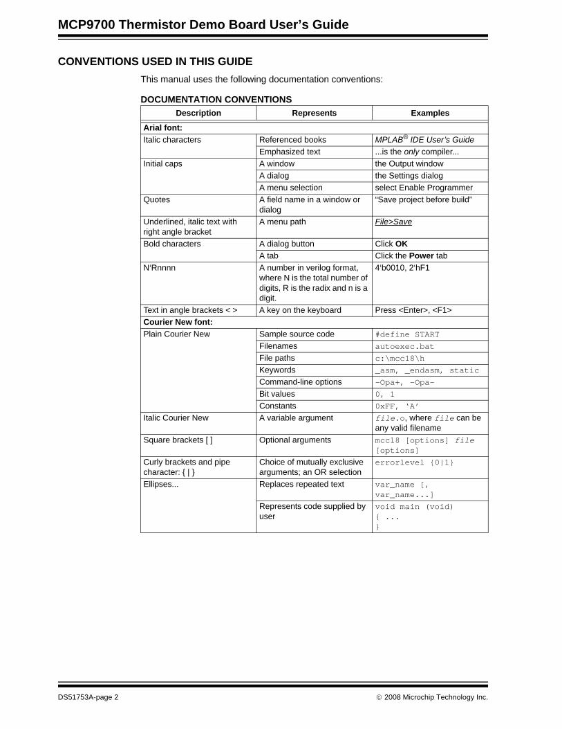
CONVENTIONS USED IN THIS GUIDEThis manual uses the following documentation conventions:
DOCUMENTATION CONVENTIONSDescription Represents Examples
Arial font:Italic characters Referenced books MPLAB® IDE User’s Guide
Emphasized text ...is the only compiler...Initial caps A window the Output window
A dialog the Settings dialogA menu selection select Enable Programmer
Quotes A field name in a window or dialog
“Save project before build”
Underlined, italic text with right angle bracket
A menu path File>Save
Bold characters A dialog button Click OKA tab Click the Power tab
N‘Rnnnn A number in verilog format, where N is the total number of digits, R is the radix and n is a digit.
4‘b0010, 2‘hF1
Text in angle brackets < > A key on the keyboard Press <Enter>, <F1>Courier New font:Plain Courier New Sample source code #define START
Filenames autoexec.batFile paths c:\mcc18\h
Keywords _asm, _endasm, static
Command-line options -Opa+, -Opa-Bit values 0, 1
Constants 0xFF, ‘A’
Italic Courier New A variable argument file.o, where file can be any valid filename
Square brackets [ ] Optional arguments mcc18 [options] file [options]
Curly brackets and pipe character: { | }
Choice of mutually exclusive arguments; an OR selection
errorlevel {0|1}
Ellipses... Replaces repeated text var_name [, var_name...]
Represents code supplied by user
void main (void){ ...}
DS51753A-page 2 © 2008 Microchip Technology Inc.
Preface
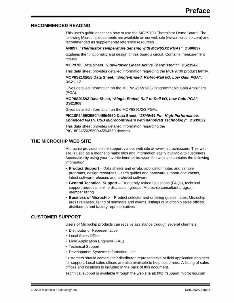
RECOMMENDED READINGThis user's guide describes how to use the MCP9700 Thermistor Demo Board. The following Microchip documents are available on our web site (www.microchip.com) and recommended as supplemental reference resources.AN897, “Thermistor Temperature Sensing with MCP6SX2 PGAs”, DS00897Explains the functionality and design of this board’s circuit. Contains measurement results.MCP9700 Data Sheet, “Low-Power Linear Active Thermistor™“, DS21942This data sheet provides detailed information regarding the MCP9700 product family.MCP6S21/2/6/8 Data Sheet, “Single-Ended, Rail-to-Rail I/O, Low Gain PGA“, DS21117Gives detailed information on the MCP6S21/2/3/6/8 Programmable Gain Amplifiers (PGA).MCP6S91/2/3 Data Sheet, “Single-Ended, Rail-to-Rail I/O, Low Gain PGA“, DS21908Gives detailed information on the MCP6S91/2/3 PGAs.PIC18F2455/2550/4455/4550 Data Sheet, “28/40/44-Pin, High-Performance, Enhanced Flash, USB Microcontrollers with nanoWatt Technology“, DS39632This data sheet provides detailed information regarding the PIC18F2455/2550/4455/4550 devices.
THE MICROCHIP WEB SITEMicrochip provides online support via our web site at www.microchip.com. This web site is used as a means to make files and information easily available to customers. Accessible by using your favorite internet browser, the web site contains the following information:• Product Support – Data sheets and errata, application notes and sample
programs, design resources, user’s guides and hardware support documents, latest software releases and archived software
• General Technical Support – Frequently Asked Questions (FAQs), technical support requests, online discussion groups, Microchip consultant program member listing
• Business of Microchip – Product selector and ordering guides, latest Microchip press releases, listing of seminars and events, listings of Microchip sales offices, distributors and factory representatives
CUSTOMER SUPPORTUsers of Microchip products can receive assistance through several channels:• Distributor or Representative• Local Sales Office• Field Application Engineer (FAE)• Technical Support• Development Systems Information LineCustomers should contact their distributor, representative or field application engineer for support. Local sales offices are also available to help customers. A listing of sales offices and locations is included in the back of this document.Technical support is available through the web site at: http://support.microchip.com
© 2008 Microchip Technology Inc. DS51753A-page 3
MCP9700 Thermistor Demo Board User’s Guide
DOCUMENT REVISION HISTORY
Revision A (August 2008)• Initial Release of this Document
DS51753A-page 4 © 2008 Microchip Technology Inc.
MCP9700 THERMISTOR
DEMO BOARD USER’S GUIDEChapter 1. Product Overview
1.1 INTRODUCTIONThe following name and assembly number are found on the MCP9700 Thermistor Demo Board’s Printed Circuit Board (PCB):• 102-00156This PCB goes by the following title:• MCP9700 Thermistor Demo BoardThis board is supported by AN897, “Thermistor Temperature-Sensing with MCP6SX2 PGAs”, (DS00897). It uses a BC Components® 2322 640 55103 NTC thermistor to detect temperature. The circuit also includes a voltage divider and a MCP6S22 Programmable Gain Amplifier (PGA) and the MCP9700 Linear Active Thermistor.• Kit Contents• MCP9700 Thermistor Demo Board• Associated Tools• Initial Set-up
1.2 WHAT IS THE MCP9700 THERMISTOR DEMO BOARD?The MCP9700 Thermistor Demo Board contains the analog circuitry to measure temperature. It uses BC Components’ 2322 640 55103 NTC thermistor to convert temperature to resistance. The thermistor is placed in a voltage divider which converts resistance to voltage. This voltage is filtered and placed at the MCP6S22 Programmable Gain Amplifier’s (PGA) CH0 input. The PGA gains and buffers the thermistor.In addition, the board includes the MCP9700 Linear Active Thermistor. The MCP9700 outputs voltage proportional to temperature. A PIC18F2550 is used to both measure the voltage output of the MCP9700 and the MCP6S22 using an integrated 10-bit Analog to Digital Converter and communicate to a PC via USB interface.Temperature can be datalogged using Microchip Thermal Management Software Graphical User Interface (GUI).
1.3 WHAT THE MCP9700 THERMISTOR DEMO BOARD KIT INCLUDES• MCP9700 Thermistor Demo Board – An assembled and tested PCB (102-00156)• Microchip Thermal Management Graphical User Interface• Analog and Interface Products Demonstration Boards CD-ROM (DS21912)
- MCP9700 Thermistor Demo Board User's Guide, (DS51753)
© 2008 Microchip Technology Inc. DS51753A-page 5
MCP9700 Thermistor Demo Board User’s Guide
NOTES:
DS51753A-page 6 © 2008 Microchip Technology Inc.
MCP9700 THERMISTORDEMO BOARD USER’S GUIDE
Chapter 2. Installation and Operation
2.1 INTRODUCTIONThe MCP9700 Thermistor Demo Board makes it easy to explore the operation of two thermistor applications using the MCP6S22 PGA and the MCP9700 Linear Active Thermistor. Items discussed in this chapter include:• Configuring the MCP9700 Thermistor Demo Board• Using the MCP9700 Thermistor Demo Board • Using the Microchip Thermal Management GUI
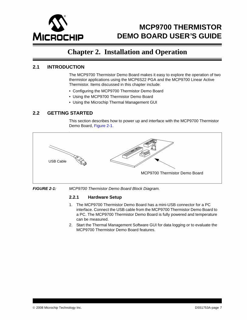
2.2 GETTING STARTEDThis section describes how to power up and interface with the MCP9700 Thermistor Demo Board, Figure 2-1..
FIGURE 2-1: MCP9700 Thermistor Demo Board Block Diagram.
2.2.1 Hardware Setup1. The MCP9700 Thermistor Demo Board has a mini-USB connector for a PC
interface. Connect the USB cable from the MCP9700 Thermistor Demo Board to a PC. The MCP9700 Thermistor Demo Board is fully powered and temperature can be measured.
2. Start the Thermal Management Software GUI for data logging or to evaluate the MCP9700 Thermistor Demo Board features.
USB Cable
MCP9700 Thermistor Demo Board
© 2008 Microchip Technology Inc. DS51753A-page 7
MCP9700 Thermistor Demo Board User’s Guide
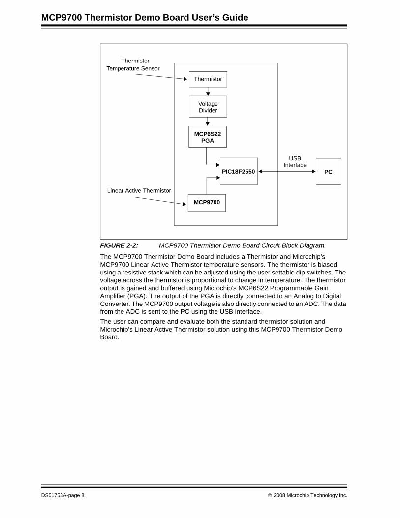
FIGURE 2-2: MCP9700 Thermistor Demo Board Circuit Block Diagram.
The MCP9700 Thermistor Demo Board includes a Thermistor and Microchip’s MCP9700 Linear Active Thermistor temperature sensors. The thermistor is biased using a resistive stack which can be adjusted using the user settable dip switches. The voltage across the thermistor is proportional to change in temperature. The thermistor output is gained and buffered using Microchip’s MCP6S22 Programmable Gain Amplifier (PGA). The output of the PGA is directly connected to an Analog to Digital Converter. The MCP9700 output voltage is also directly connected to an ADC. The data from the ADC is sent to the PC using the USB interface.The user can compare and evaluate both the standard thermistor solution and Microchip’s Linear Active Thermistor solution using this MCP9700 Thermistor Demo Board.
Thermistor
Thermistor
VoltageDivider
MCP6S22
Temperature Sensor
PGA
PIC18F2550
MCP9700
Linear Active Thermistor
PC
USBInterface
DS51753A-page 8 © 2008 Microchip Technology Inc.
Installation and Operation
2.3 CONFIGURING BOARD
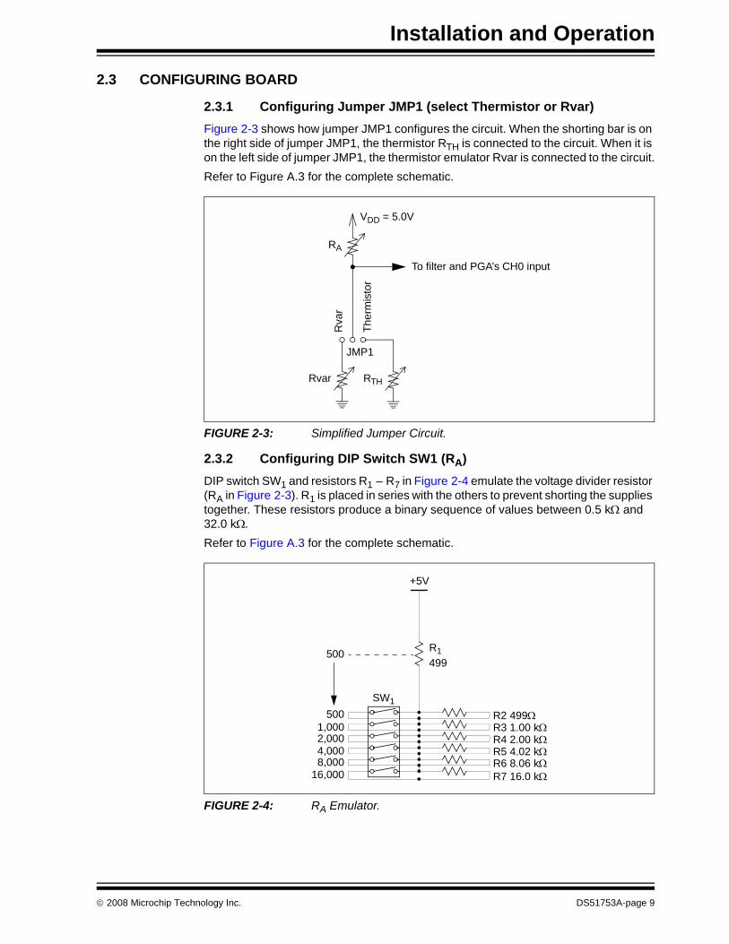
2.3.1 Configuring Jumper JMP1 (select Thermistor or Rvar)Figure 2-3 shows how jumper JMP1 configures the circuit. When the shorting bar is on the right side of jumper JMP1, the thermistor RTH is connected to the circuit. When it is on the left side of jumper JMP1, the thermistor emulator Rvar is connected to the circuit.Refer to Figure A.3 for the complete schematic.
FIGURE 2-3: Simplified Jumper Circuit.
2.3.2 Configuring DIP Switch SW1 (RA)DIP switch SW1 and resistors R1 – R7 in Figure 2-4 emulate the voltage divider resistor (RA in Figure 2-3). R1 is placed in series with the others to prevent shorting the supplies together. These resistors produce a binary sequence of values between 0.5 kΩ and 32.0 kΩ.Refer to Figure A.3 for the complete schematic.
FIGURE 2-4: RA Emulator.
Rva
r
Ther
mis
tor
Rvar RTH
JMP1
VDD = 5.0V
RA
To filter and PGA’s CH0 input
5001,0002,0004,0008,000
16,000
R1499
+5V
SW1
R2 499ΩR3 1.00 kΩR4 2.00 kΩR5 4.02 kΩR6 8.06 kΩR7 16.0 kΩ
500
© 2008 Microchip Technology Inc. DS51753A-page 9
MCP9700 Thermistor Demo Board User’s Guide
Each resistor with its switch (in SW1) pointing to the right, away from the silk screen resistor values, is not added into the total for RA (it shorts that resistor). Each resistor with its switch (in SW1) pointing to the left, towards the silk screen resistor values, is added into the total for RA. As an example, if the top four switches are to the right, and the bottom two are to the left, then RA is calculated as 500 + 0 + 0 + 0 + 0 + 8,000 + 16,000 = 24,500Ω.
2.3.3 Using the Thermistor (RTH)In Appendix A. “Schematic and Layouts”, R21 is the thermistor (RTH in Figure 2-3). The resistance changes depending on temperature; see AN897, “Thermistor Temperature Sensing with MCP6SX2 PGAs” (DS00897).
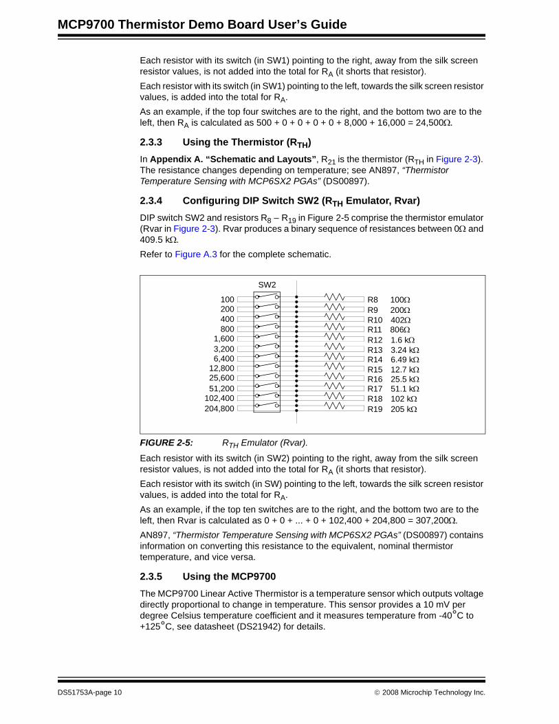
2.3.4 Configuring DIP Switch SW2 (RTH Emulator, Rvar)DIP switch SW2 and resistors R8 – R19 in Figure 2-5 comprise the thermistor emulator (Rvar in Figure 2-3). Rvar produces a binary sequence of resistances between 0Ω and 409.5 kΩ.Refer to Figure A.3 for the complete schematic.
FIGURE 2-5: RTH Emulator (Rvar).
Each resistor with its switch (in SW2) pointing to the right, away from the silk screen resistor values, is not added into the total for RA (it shorts that resistor). Each resistor with its switch (in SW) pointing to the left, towards the silk screen resistor values, is added into the total for RA. As an example, if the top ten switches are to the right, and the bottom two are to the left, then Rvar is calculated as 0 + 0 + ... + 0 + 102,400 + 204,800 = 307,200Ω.AN897, “Thermistor Temperature Sensing with MCP6SX2 PGAs” (DS00897) contains information on converting this resistance to the equivalent, nominal thermistor temperature, and vice versa.
2.3.5 Using the MCP9700The MCP9700 Linear Active Thermistor is a temperature sensor which outputs voltage directly proportional to change in temperature. This sensor provides a 10 mV per degree Celsius temperature coefficient and it measures temperature from -40°C to +125°C, see datasheet (DS21942) for details.
100200400800
1,6003,2006,400
12,80025,60051,200
102,400204,800
SW2
R8 100ΩR9 200ΩR10 402ΩR11 806ΩR12 1.6 kΩR13 3.24 kΩR14 6.49 kΩR15 12.7 kΩR16 25.5 kΩR17 51.1 kΩR18 102 kΩR19 205 kΩ
DS51753A-page 10 © 2008 Microchip Technology Inc.
Installation and Operation
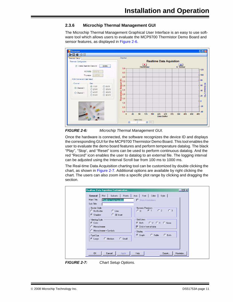
2.3.6 Microchip Thermal Management GUIThe Microchip Thermal Management Graphical User Interface is an easy to use soft-ware tool which allows users to evaluate the MCP9700 Thermistor Demo Board and sensor features, as displayed in Figure 2-6.
FIGURE 2-6: Microchip Thermal Management GUI.
Once the hardware is connected, the software recognizes the device ID and displays the corresponding GUI for the MCP9700 Thermistor Demo Board. This tool enables the user to evaluate the demo board features and perform temperature datalog. The black “Play”, “Stop’, and “Reset” icons can be used to perform continuous datalog. And the red “Record” icon enables the user to datalog to an external file. The logging interval can be adjusted using the Interval Scroll bar from 100 ms to 1000 ms. The Real-time Data Acquisition charting tool can be customized by double clicking the chart, as shown in Figure 2-7. Additional options are available by right clicking the chart. The users can also zoom into a specific plot range by clicking and dragging the section.
FIGURE 2-7: Chart Setup Options.
© 2008 Microchip Technology Inc. DS51753A-page 11

MCP9700 Thermistor Demo Board User’s Guide
NOTES:
DS51753A-page 12 © 2008 Microchip Technology Inc.
MCP9700 THERMISTORDEMO BOARD USER’S GUIDE
Appendix A. Schematic and Layouts
A.1 INTRODUCTIONThis appendix contains the following schematics and layouts for the MCP9700 Thermistor Demo Board:• Board Schematic• Board - Top Layer• Board - Silk-screen Layer• Board - Bottom Layer
© 2008 Microchip Technology Inc. DS51753A-page 13
MCP9700 Thermistor Demo Board User’s Guide
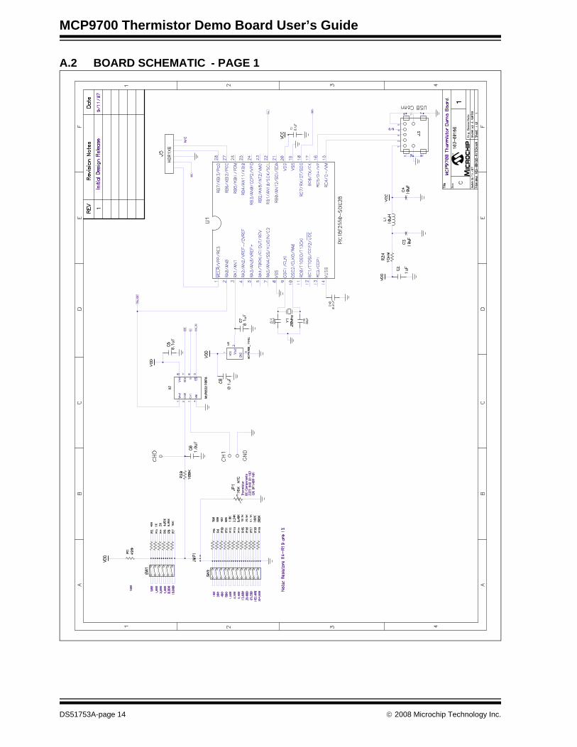
A.2 BOARD SCHEMATIC - PAGE 1
M
DS51753A-page 14 © 2008 Microchip Technology Inc.
Schematic and Layouts
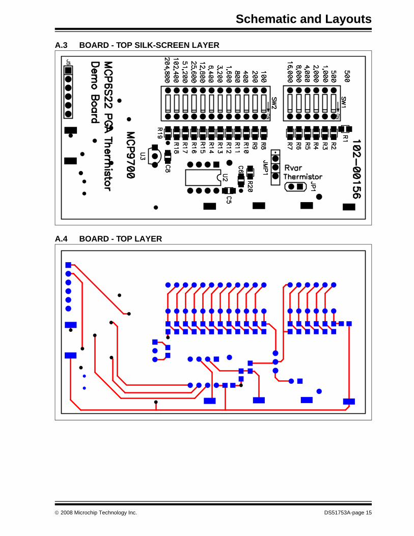
A.3 BOARD - TOP SILK-SCREEN LAYER
A.4 BOARD - TOP LAYER
© 2008 Microchip Technology Inc. DS51753A-page 15
MCP9700 Thermistor Demo Board User’s Guide
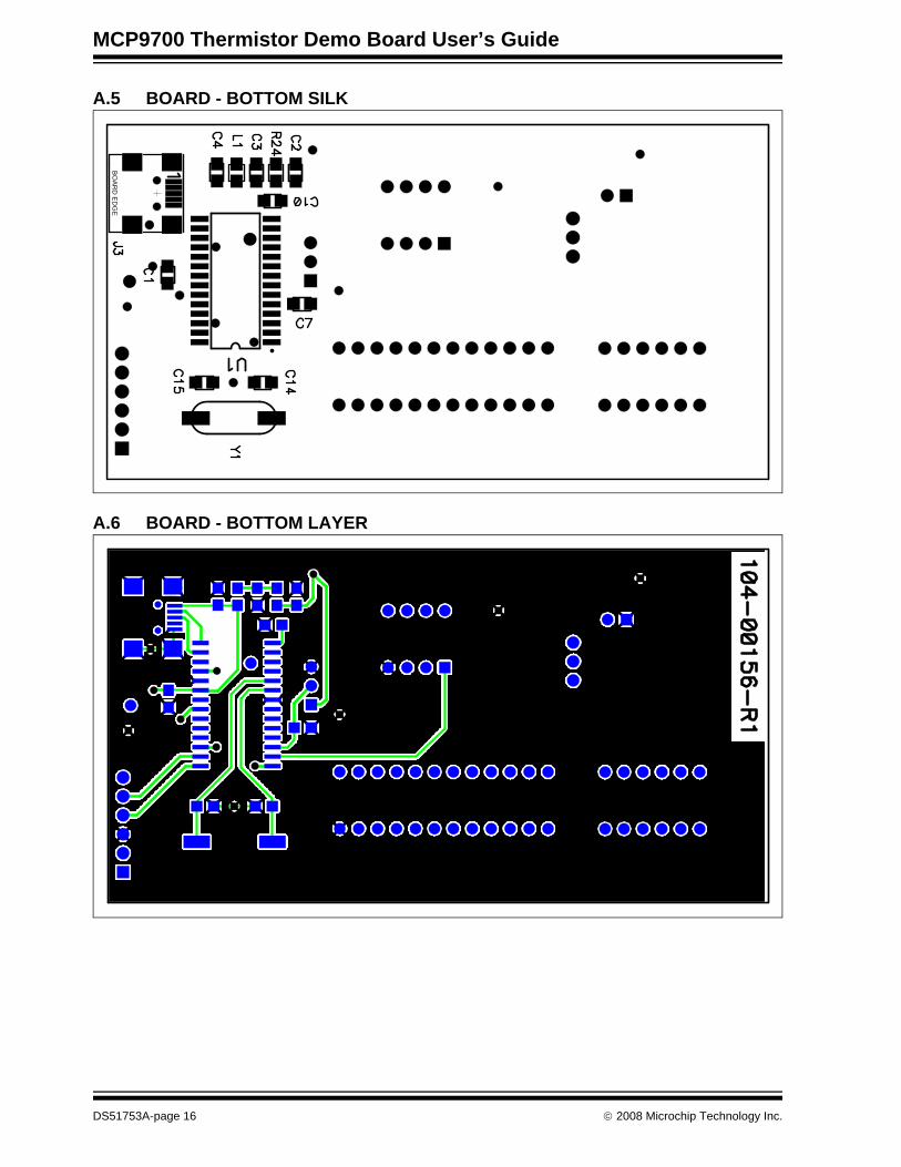
A.5 BOARD - BOTTOM SILK
A.6 BOARD - BOTTOM LAYER
BO
AR
D E
DG
E
DS51753A-page 16 © 2008 Microchip Technology Inc.
MCP9700 THERMISTORDEMO BOARD USER’S GUIDE
Appendix B. Bill Of Materials (BOM)
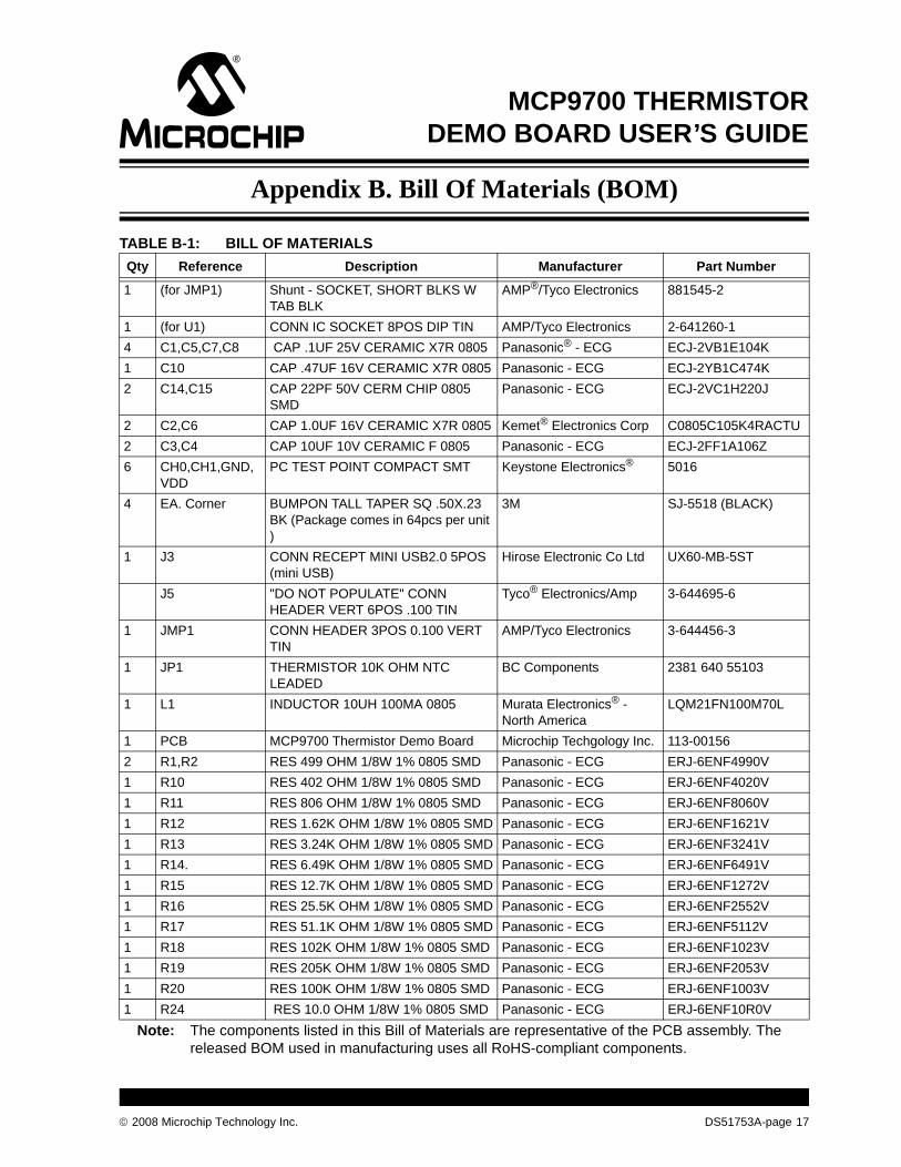
TABLE B-1: BILL OF MATERIALSQty Reference Description Manufacturer Part Number
1 (for JMP1) Shunt - SOCKET, SHORT BLKS W TAB BLK
AMP®/Tyco Electronics 881545-2
1 (for U1) CONN IC SOCKET 8POS DIP TIN AMP/Tyco Electronics 2-641260-14 C1,C5,C7,C8 CAP .1UF 25V CERAMIC X7R 0805 Panasonic® - ECG ECJ-2VB1E104K1 C10 CAP .47UF 16V CERAMIC X7R 0805 Panasonic - ECG ECJ-2YB1C474K2 C14,C15 CAP 22PF 50V CERM CHIP 0805
SMDPanasonic - ECG ECJ-2VC1H220J
2 C2,C6 CAP 1.0UF 16V CERAMIC X7R 0805 Kemet® Electronics Corp C0805C105K4RACTU2 C3,C4 CAP 10UF 10V CERAMIC F 0805 Panasonic - ECG ECJ-2FF1A106Z6 CH0,CH1,GND,
VDDPC TEST POINT COMPACT SMT Keystone Electronics® 5016
4 EA. Corner BUMPON TALL TAPER SQ .50X.23 BK (Package comes in 64pcs per unit )
3M SJ-5518 (BLACK)
1 J3 CONN RECEPT MINI USB2.0 5POS (mini USB)
Hirose Electronic Co Ltd UX60-MB-5ST
J5 "DO NOT POPULATE" CONN HEADER VERT 6POS .100 TIN
Tyco® Electronics/Amp 3-644695-6
1 JMP1 CONN HEADER 3POS 0.100 VERT TIN
AMP/Tyco Electronics 3-644456-3
1 JP1 THERMISTOR 10K OHM NTC LEADED
BC Components 2381 640 55103
1 L1 INDUCTOR 10UH 100MA 0805 Murata Electronics® - North America
LQM21FN100M70L
1 PCB MCP9700 Thermistor Demo Board Microchip Techgology Inc. 113-001562 R1,R2 RES 499 OHM 1/8W 1% 0805 SMD Panasonic - ECG ERJ-6ENF4990V1 R10 RES 402 OHM 1/8W 1% 0805 SMD Panasonic - ECG ERJ-6ENF4020V1 R11 RES 806 OHM 1/8W 1% 0805 SMD Panasonic - ECG ERJ-6ENF8060V1 R12 RES 1.62K OHM 1/8W 1% 0805 SMD Panasonic - ECG ERJ-6ENF1621V1 R13 RES 3.24K OHM 1/8W 1% 0805 SMD Panasonic - ECG ERJ-6ENF3241V1 R14. RES 6.49K OHM 1/8W 1% 0805 SMD Panasonic - ECG ERJ-6ENF6491V1 R15 RES 12.7K OHM 1/8W 1% 0805 SMD Panasonic - ECG ERJ-6ENF1272V1 R16 RES 25.5K OHM 1/8W 1% 0805 SMD Panasonic - ECG ERJ-6ENF2552V1 R17 RES 51.1K OHM 1/8W 1% 0805 SMD Panasonic - ECG ERJ-6ENF5112V1 R18 RES 102K OHM 1/8W 1% 0805 SMD Panasonic - ECG ERJ-6ENF1023V1 R19 RES 205K OHM 1/8W 1% 0805 SMD Panasonic - ECG ERJ-6ENF2053V1 R20 RES 100K OHM 1/8W 1% 0805 SMD Panasonic - ECG ERJ-6ENF1003V1 R24 RES 10.0 OHM 1/8W 1% 0805 SMD Panasonic - ECG ERJ-6ENF10R0V
Note: The components listed in this Bill of Materials are representative of the PCB assembly. The released BOM used in manufacturing uses all RoHS-compliant components.
© 2008 Microchip Technology Inc. DS51753A-page 17
MCP9700 Thermistor Demo Board User’s Guide
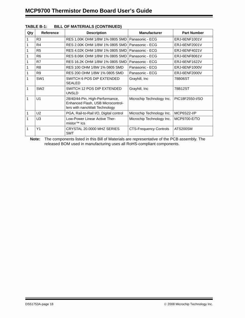
1 R3 RES 1.00K OHM 1/8W 1% 0805 SMD Panasonic - ECG ERJ-6ENF1001V1 R4 RES 2.00K OHM 1/8W 1% 0805 SMD Panasonic - ECG ERJ-6ENF2001V1 R5 RES 4.02K OHM 1/8W 1% 0805 SMD Panasonic - ECG ERJ-6ENF4021V1 R6 RES 8.06K OHM 1/8W 1% 0805 SMD Panasonic - ECG ERJ-6ENF8061V1 R7 RES 16.2K OHM 1/8W 1% 0805 SMD Panasonic - ECG ERJ-6ENF1622V1 R8 RES 100 OHM 1/8W 1% 0805 SMD Panasonic - ECG ERJ-6ENF1000V1 R9 RES 200 OHM 1/8W 1% 0805 SMD Panasonic - ECG ERJ-6ENF2000V1 SW1 SWITCH 6 POS DIP EXTENDED
SEALEDGrayhill, Inc 78B06ST
1 SW2 SWITCH 12 POS DIP EXTENDED UNSLD
Grayhill, Inc 78B12ST
1 U1 28/40/44-Pin, High-Performance, Enhanced Flash, USB Microcontrol-lers with nanoWatt Technology
Microchip Technology Inc. PIC18F2550-I/SO
1 U2 PGA, Rail-to-Rail I/O, Digital control Microchip Technology Inc. MCP6S22-I/P1 U3 Low-Power Linear Active Ther-
mistor™ IcsMicrochip Technology Inc. MCP9700-E/TO
1 Y1 CRYSTAL 20.0000 MHZ SERIES SMT
CTS-Frequency Controls ATS200SM
TABLE B-1: BILL OF MATERIALS (CONTINUED)Qty Reference Description Manufacturer Part Number
Note: The components listed in this Bill of Materials are representative of the PCB assembly. The released BOM used in manufacturing uses all RoHS-compliant components.
DS51753A-page 18 © 2008 Microchip Technology Inc.
Bill Of Materials (BOM)
NOTES:
© 2008 Microchip Technology Inc. DS51753A-page 19
DS51753A-page 20 © 2008 Microchip Technology Inc.
AMERICASCorporate Office2355 West Chandler Blvd.Chandler, AZ 85224-6199Tel: 480-792-7200 Fax: 480-792-7277Technical Support: http://support.microchip.comWeb Address: www.microchip.comAtlantaDuluth, GA Tel: 678-957-9614 Fax: 678-957-1455BostonWestborough, MA Tel: 774-760-0087 Fax: 774-760-0088ChicagoItasca, IL Tel: 630-285-0071 Fax: 630-285-0075DallasAddison, TX Tel: 972-818-7423 Fax: 972-818-2924DetroitFarmington Hills, MI Tel: 248-538-2250Fax: 248-538-2260KokomoKokomo, IN Tel: 765-864-8360Fax: 765-864-8387Los AngelesMission Viejo, CA Tel: 949-462-9523 Fax: 949-462-9608Santa ClaraSanta Clara, CA Tel: 408-961-6444Fax: 408-961-6445TorontoMississauga, Ontario, CanadaTel: 905-673-0699 Fax: 905-673-6509
ASIA/PACIFICAsia Pacific OfficeSuites 3707-14, 37th FloorTower 6, The GatewayHarbour City, KowloonHong KongTel: 852-2401-1200Fax: 852-2401-3431Australia - SydneyTel: 61-2-9868-6733Fax: 61-2-9868-6755China - BeijingTel: 86-10-8528-2100 Fax: 86-10-8528-2104China - ChengduTel: 86-28-8665-5511Fax: 86-28-8665-7889China - Hong Kong SARTel: 852-2401-1200 Fax: 852-2401-3431China - NanjingTel: 86-25-8473-2460Fax: 86-25-8473-2470China - QingdaoTel: 86-532-8502-7355Fax: 86-532-8502-7205China - ShanghaiTel: 86-21-5407-5533 Fax: 86-21-5407-5066China - ShenyangTel: 86-24-2334-2829Fax: 86-24-2334-2393China - ShenzhenTel: 86-755-8203-2660 Fax: 86-755-8203-1760China - WuhanTel: 86-27-5980-5300Fax: 86-27-5980-5118China - XiamenTel: 86-592-2388138 Fax: 86-592-2388130China - XianTel: 86-29-8833-7252Fax: 86-29-8833-7256China - ZhuhaiTel: 86-756-3210040 Fax: 86-756-3210049
ASIA/PACIFICIndia - BangaloreTel: 91-80-4182-8400 Fax: 91-80-4182-8422India - New DelhiTel: 91-11-4160-8631Fax: 91-11-4160-8632India - PuneTel: 91-20-2566-1512Fax: 91-20-2566-1513Japan - YokohamaTel: 81-45-471- 6166 Fax: 81-45-471-6122Korea - DaeguTel: 82-53-744-4301Fax: 82-53-744-4302Korea - SeoulTel: 82-2-554-7200Fax: 82-2-558-5932 or 82-2-558-5934Malaysia - Kuala LumpurTel: 60-3-6201-9857Fax: 60-3-6201-9859Malaysia - PenangTel: 60-4-227-8870Fax: 60-4-227-4068Philippines - ManilaTel: 63-2-634-9065Fax: 63-2-634-9069SingaporeTel: 65-6334-8870Fax: 65-6334-8850Taiwan - Hsin ChuTel: 886-3-572-9526Fax: 886-3-572-6459Taiwan - KaohsiungTel: 886-7-536-4818Fax: 886-7-536-4803Taiwan - TaipeiTel: 886-2-2500-6610 Fax: 886-2-2508-0102Thailand - BangkokTel: 66-2-694-1351Fax: 66-2-694-1350
EUROPEAustria - WelsTel: 43-7242-2244-39Fax: 43-7242-2244-393Denmark - CopenhagenTel: 45-4450-2828 Fax: 45-4485-2829France - ParisTel: 33-1-69-53-63-20 Fax: 33-1-69-30-90-79Germany - MunichTel: 49-89-627-144-0 Fax: 49-89-627-144-44Italy - Milan Tel: 39-0331-742611 Fax: 39-0331-466781Netherlands - DrunenTel: 31-416-690399 Fax: 31-416-690340Spain - MadridTel: 34-91-708-08-90Fax: 34-91-708-08-91UK - WokinghamTel: 44-118-921-5869Fax: 44-118-921-5820
WORLDWIDE SALES AND SERVICE
01/02/08