md3 installation manual 090216 no ac(12-24vdc only) … 4k...support ... megadome® 4k 6. prepare...
TRANSCRIPT
MegaDome® 4K Installation Manual
Models:
8 Megapixel
AV08ZMD-400
You created this PDF from an application that is not licensed to print to novaPDF printer (http://www.novapdf.com)
Installation Manual
Page | 2 [email protected]
+1.818.937.0700 877.CAMERA.8 www.arecontvision.com [email protected]
MegaDome® 4K
Contents
Package Contents ............................................................................................................................................ 3
Camera Overview ............................................................................................................................................. 6
Installation ......................................................................................................................................................... 7
Surface Mount ..............................................................................................................................................10
Wall Mount ....................................................................................................................................................13
Pendant Mount ............................................................................................................................................16
Pole Mount ...................................................................................................................................................19
Corner Mount ...............................................................................................................................................21
Electrical Box Adapter ................................................................................................................................23
Adjusting the Pan, Tilt and Focus...................................................................................................................24
Auxiliary I/O Functions ....................................................................................................................................26
Camera Power Up ...........................................................................................................................................30
Reset to Factory Default .................................................................................................................................32
SD Card Set-up ................................................................................................................................................33
SD Card Tab ....................................................................................................................................................36
Camera Discovery, Setup, and Configuration ...............................................................................................37
Network Protocols............................................................................................................................................37
General Remote Focus ...................................................................................................................................38
Refined Remote Focus ...................................................................................................................................39
AV IP Utility Focus Tab ...................................................................................................................................41
Mounting Templates ........................................................................................................................................42
Support .............................................................................................................................................................43
You created this PDF from an application that is not licensed to print to novaPDF printer (http://www.novapdf.com)
Installation Manual
Page | 3 [email protected]
+1.818.937.0700 877.CAMERA.8 www.arecontvision.com [email protected]
MegaDome® 4K
CAUTION! 1. Do not attempt to service a damaged unit yourself. Refer all servicing to qualified service
personnel. 2. Wiring methods shall be in accordance with the National Electrical Code/NFPA 70/ANSI, and
with all local codes and authorities having jurisdiction. Wiring should be UL Listed and/or
Recognized wire suitable for the application.
3. Always use hardware e.g. screws, anchors, bolts, locking nuts etc. which are compatible with
mounting surface and of sufficient length and construction to insure a secure mount.
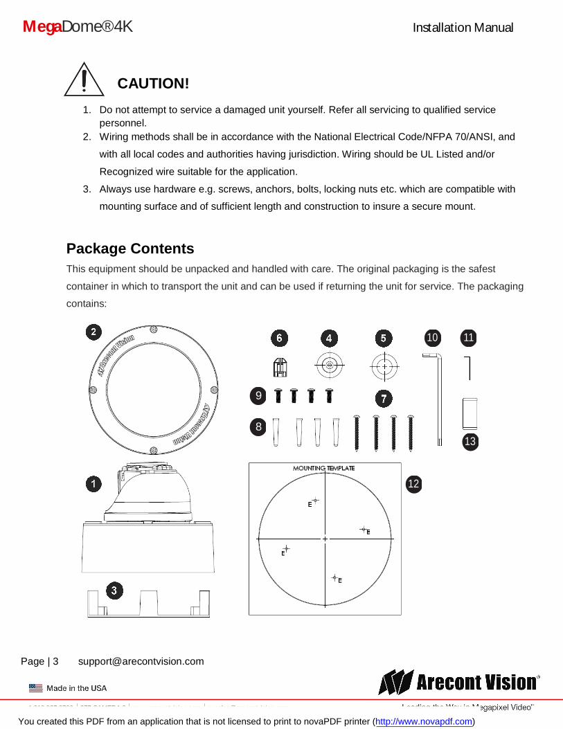
Package Contents
This equipment should be unpacked and handled with care. The original packaging is the safest
container in which to transport the unit and can be used if returning the unit for service. The packaging
contains:
10
8
9
11
12
13
You created this PDF from an application that is not licensed to print to novaPDF printer (http://www.novapdf.com)
Installation Manual
Page | 4 [email protected]
+1.818.937.0700 877.CAMERA.8 www.arecontvision.com [email protected]
MegaDome® 4K
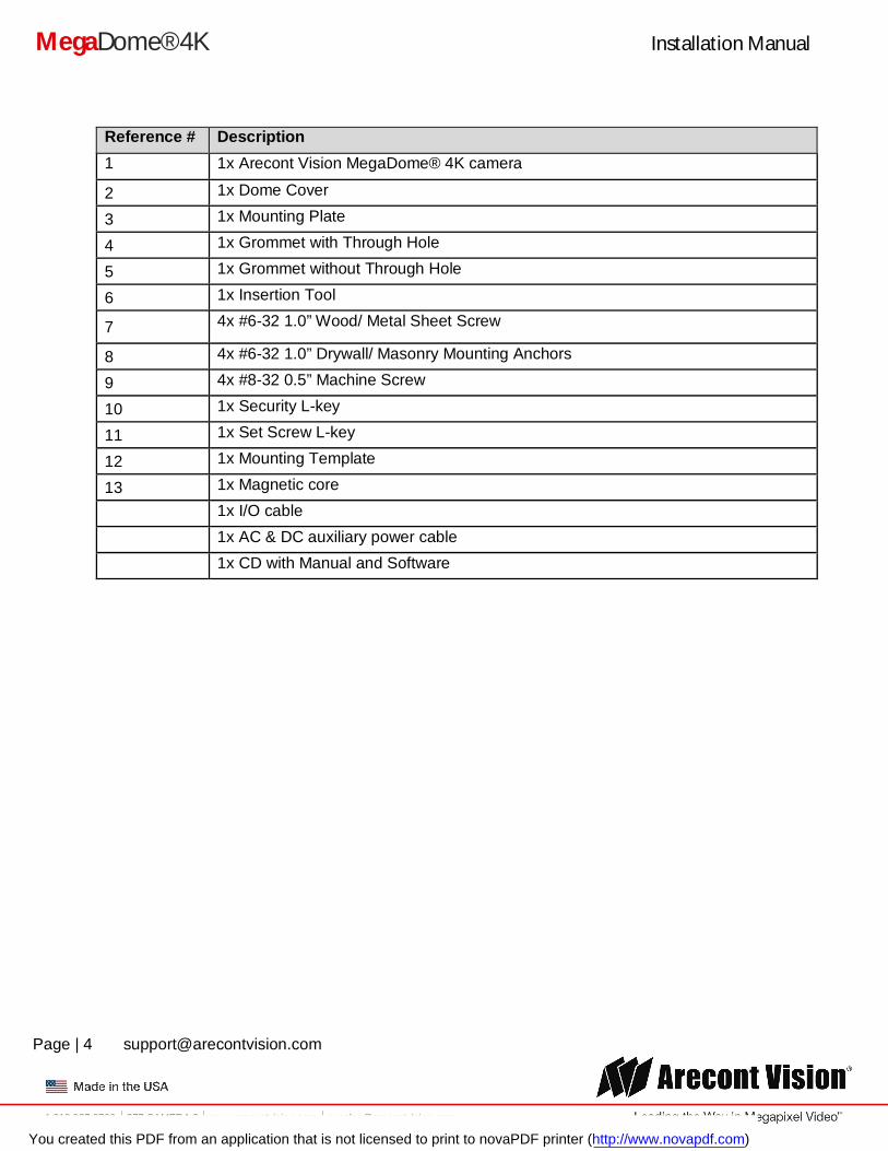
Reference # Description 1 1x Arecont Vision MegaDome® 4K camera
2 1x Dome Cover
3 1x Mounting Plate
4 1x Grommet with Through Hole
5 1x Grommet without Through Hole
6 1x Insertion Tool
7 4x #6-32 1.0” Wood/ Metal Sheet Screw
8 4x #6-32 1.0” Drywall/ Masonry Mounting Anchors
9 4x #8-32 0.5” Machine Screw
10 1x Security L-key
11 1x Set Screw L-key
12 1x Mounting Template
13 1x Magnetic core
1x I/O cable
1x AC & DC auxiliary power cable
1x CD with Manual and Software
You created this PDF from an application that is not licensed to print to novaPDF printer (http://www.novapdf.com)
Installation Manual
Page | 5 [email protected]
+1.818.937.0700 877.CAMERA.8 www.arecontvision.com [email protected]
MegaDome® 4K
Warranty Information Global (3 Year) Limited Warranty
ARECONT VISION warrants to Purchaser (and only Purchaser) (the “Limited Warranty”), that: (a) each Product shall be free from material defects in material and workmanship for a period of thirty-six (36) months from the date of shipment (the “Warranty Period”); (b) during the Warranty Period, the Products will materially conform with the specification in the applicable documentation; (c) all licensed programs accompanying the Product (the “Licensed Programs”) will materially conform with applicable specifications. Notwithstanding the preceding provisions, ARECONT VISION shall have no obligation or responsibility with respect to any Product that (i) has been modified or altered without ARECONT VISION’s written authorization; (ii) has not been used in accordance with applicable documentation; (iii) has been subjected to unusual stress, neglect, misuse, abuse, improper storage, testing or connection; or unauthorized repair; or (iv) is no longer covered under the Warranty Period. ARECONT VISION MAKE NO WARRANTIES OR CONDITIONS, EXPRESS, IMPLIED, STATUTORY OR OTHERWISE, OTHER THAN THE EXPRESS LIMITED WARRANTIES MADE BY ARECONT VISION ABOVE, AND ARECONT VISION HEREBY SPECIFICALLY DISCLAIMS ALL OTHER EXPRESS, STATUTORY AND IMPLIED WARRANTIES AND CONDITIONS, INCLUDING THE IMPLIED WARRANTIES OF MERCHANTABILITY, FITNESS FOR A PARTICULAR PURPOSE, NON-INFRINGEMENT AND THE IMPLIED CONDITION OF SATISFACTORY QUALITY. ALL LICENSED PROGRAMS ARE LICENSED ON AN “AS IS” BASIS WITHOUT WARRANTY. ARECONT VISION DOES NOT WARRANT THAT (I) THE OPERATION OF THE PRODUCTS OR PARTS WILL BE UNINTERRUPTED OR ERROR FREE; (II) THE PRODUCTS OR PARTS AND DOCUMENTATION WILL MEET THE END USERS’ REQUIREMENTS; (III) THE PRODUCTS OR PARTS WILL OPERATE IN COMBINATIONS AND CONFIGURATIONS SELECTED BY THE END USER; OTHER THAN COMBINATIONS AND CONFIGURATIONS WITH PARTS OR OTHER PRODUCTS AUTHORIZED BY ARECONT VISION OR (IV) THAT ALL LICENSED PROGRAM ERRORS WILL BE CORRECTED.
For RMA and Advance Replacement information visit http://www.arecontvision.com
You created this PDF from an application that is not licensed to print to novaPDF printer (http://www.novapdf.com)
Installation Manual
Page | 6 [email protected]
+1.818.937.0700 877.CAMERA.8 www.arecontvision.com [email protected]
MegaDome® 4K
Camera Overview
The AV08ZMD-400 4K 8-Megapixel/1080p MegaDome® 4K dual mode network camera is the new generation of Arecont Vision’s full line of H.264 MegaDome® cameras. This fully compliant implementation of H.264 (MPEG-4, Part 10) provides full 3840 x 2160 megapixel resolution at full video frame rates of 30 frames per second (fps) at 8-megapixel and 60fps in 1080p binned mode. The AV08ZMD-400 camera line provides an all-in-one solution with integrated 8-megapixel day/night camera, remote focus, remote zoom, P-Iris, 4.4-10mm lens, SDHC card.
With the features of SNAPstream™ to reduce bandwidth without impacting image quality, scaling, binned mode, privacy masking, extended motion detection and flexible cropping, the AV08ZMD-400 is a high sensitivity, Power over Ethernet (PoE - IEEE 802.3af) compliant camera. Built with Arecont Vision’s massively-parallel MegaVideo® processing technology, this camera offers more than 27-times the resolution of standard resolution IP cameras with the ability to output full real-time frame rates and deliver high-quality megapixel imaging for both indoor and outdoor applications.
You created this PDF from an application that is not licensed to print to novaPDF printer (http://www.novapdf.com)
Installation Manual
Page | 7 [email protected]
+1.818.937.0700 877.CAMERA.8 www.arecontvision.com [email protected]
MegaDome® 4K
Installation
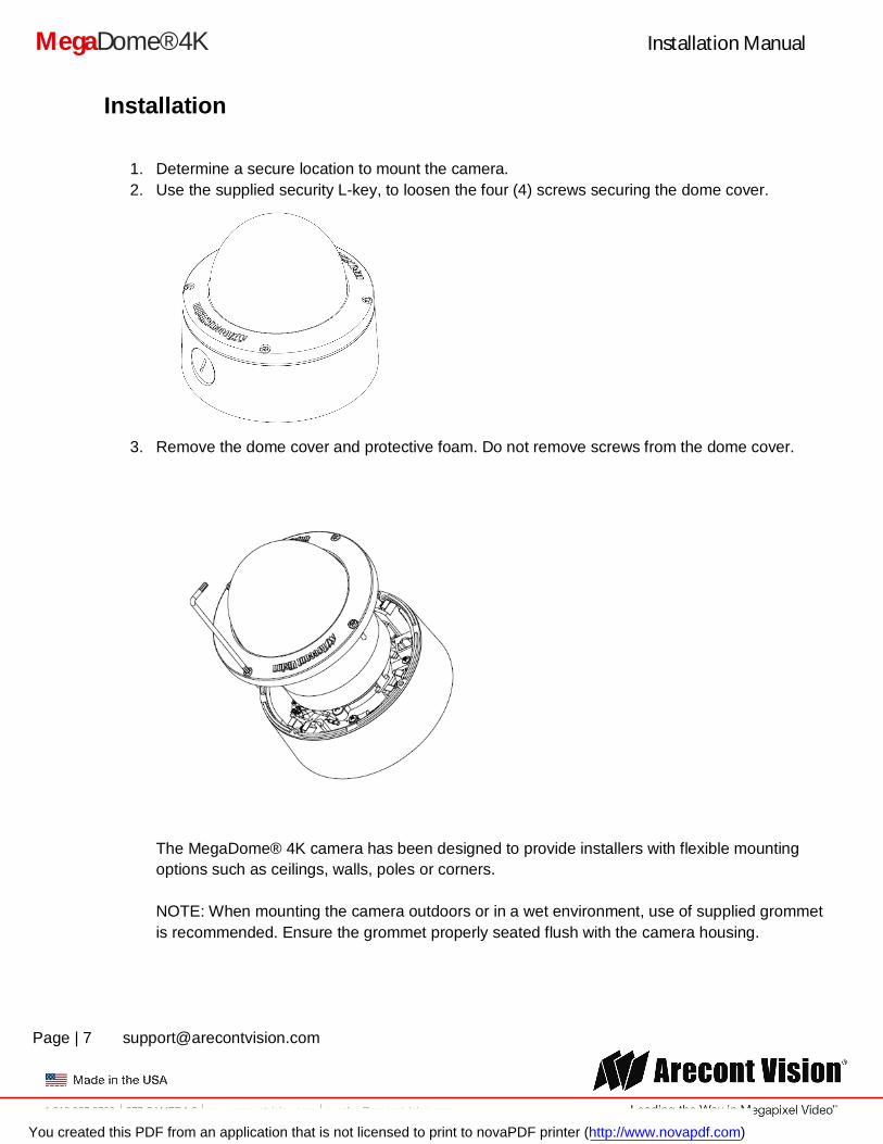
1. Determine a secure location to mount the camera. 2. Use the supplied security L-key, to loosen the four (4) screws securing the dome cover.
3. Remove the dome cover and protective foam. Do not remove screws from the dome cover.
The MegaDome® 4K camera has been designed to provide installers with flexible mounting options such as ceilings, walls, poles or corners. NOTE: When mounting the camera outdoors or in a wet environment, use of supplied grommet is recommended. Ensure the grommet properly seated flush with the camera housing.
You created this PDF from an application that is not licensed to print to novaPDF printer (http://www.novapdf.com)
Installation Manual
Page | 8 [email protected]
+1.818.937.0700 877.CAMERA.8 www.arecontvision.com [email protected]
MegaDome® 4K
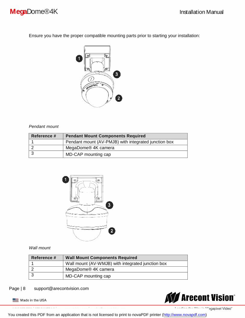
Ensure you have the proper compatible mounting parts prior to starting your installation:
Pendant mount
Reference # Pendant Mount Components Required 1 Pendant mount (AV-PMJB) with integrated junction box 2 MegaDome® 4K camera 3 MD-CAP mounting cap
Wall mount
Reference # Wall Mount Components Required 1 Wall mount (AV-WMJB) with integrated junction box 2 MegaDome® 4K camera 3 MD-CAP mounting cap
You created this PDF from an application that is not licensed to print to novaPDF printer (http://www.novapdf.com)
Installation Manual
Page | 9 [email protected]
+1.818.937.0700 877.CAMERA.8 www.arecontvision.com [email protected]
MegaDome® 4K
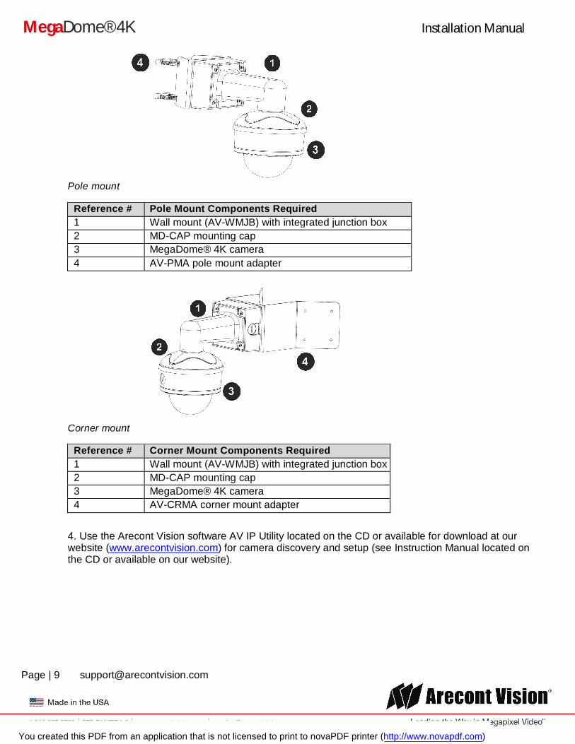
Pole mount
Reference # Pole Mount Components Required 1 Wall mount (AV-WMJB) with integrated junction box 2 MD-CAP mounting cap 3 MegaDome® 4K camera 4 AV-PMA pole mount adapter
Corner mount
Reference # Corner Mount Components Required 1 Wall mount (AV-WMJB) with integrated junction box 2 MD-CAP mounting cap 3 MegaDome® 4K camera 4 AV-CRMA corner mount adapter
4. Use the Arecont Vision software AV IP Utility located on the CD or available for download at our website (www.arecontvision.com) for camera discovery and setup (see Instruction Manual located on the CD or available on our website).
You created this PDF from an application that is not licensed to print to novaPDF printer (http://www.novapdf.com)
Installation Manual
Page | 10 [email protected]
+1.818.937.0700 877.CAMERA.8 www.arecontvision.com [email protected]
MegaDome® 4K
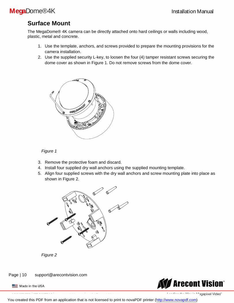
Surface Mount The MegaDome® 4K camera can be directly attached onto hard ceilings or walls including wood, plastic, metal and concrete.
1. Use the template, anchors, and screws provided to prepare the mounting provisions for the camera installation.
2. Use the supplied security L-key, to loosen the four (4) tamper resistant screws securing the dome cover as shown in Figure 1. Do not remove screws from the dome cover.
Figure 1
3. Remove the protective foam and discard. 4. Install four supplied dry wall anchors using the supplied mounting template. 5. Align four supplied screws with the dry wall anchors and screw mounting plate into place as
shown in Figure 2.
Figure 2
You created this PDF from an application that is not licensed to print to novaPDF printer (http://www.novapdf.com)
Installation Manual
Page | 11 [email protected]
+1.818.937.0700 877.CAMERA.8 www.arecontvision.com [email protected]
MegaDome® 4K
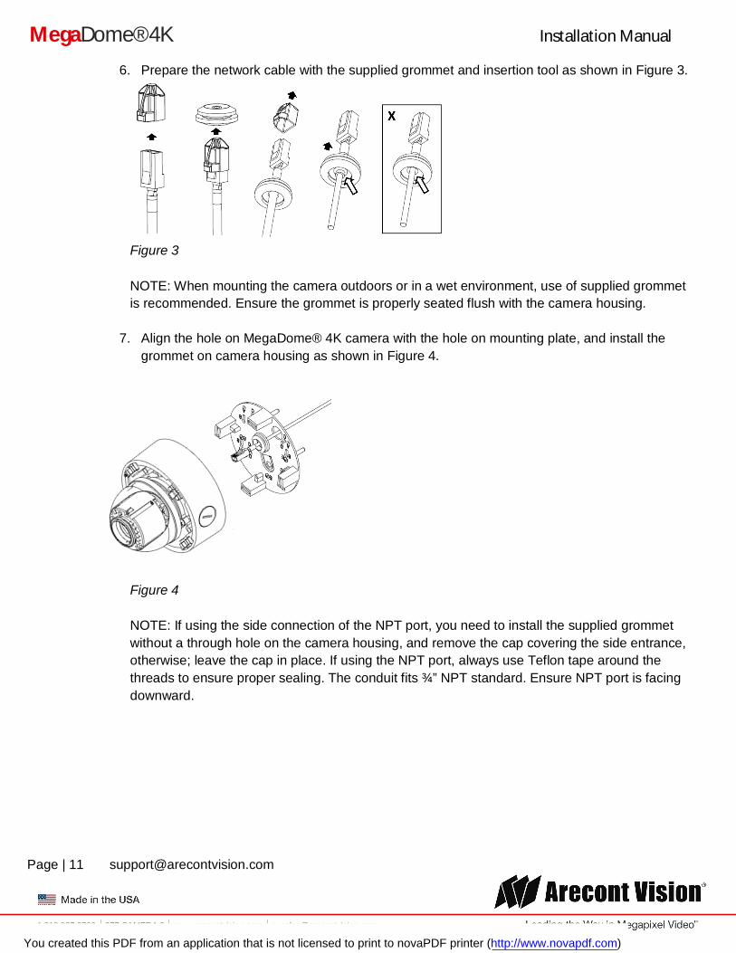
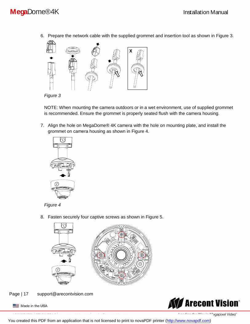
6. Prepare the network cable with the supplied grommet and insertion tool as shown in Figure 3.
Figure 3 NOTE: When mounting the camera outdoors or in a wet environment, use of supplied grommet is recommended. Ensure the grommet is properly seated flush with the camera housing.
7. Align the hole on MegaDome® 4K camera with the hole on mounting plate, and install the
grommet on camera housing as shown in Figure 4.
Figure 4 NOTE: If using the side connection of the NPT port, you need to install the supplied grommet without a through hole on the camera housing, and remove the cap covering the side entrance, otherwise; leave the cap in place. If using the NPT port, always use Teflon tape around the threads to ensure proper sealing. The conduit fits ¾” NPT standard. Ensure NPT port is facing downward.
You created this PDF from an application that is not licensed to print to novaPDF printer (http://www.novapdf.com)
Installation Manual
Page | 12 [email protected]
+1.818.937.0700 877.CAMERA.8 www.arecontvision.com [email protected]
MegaDome® 4K
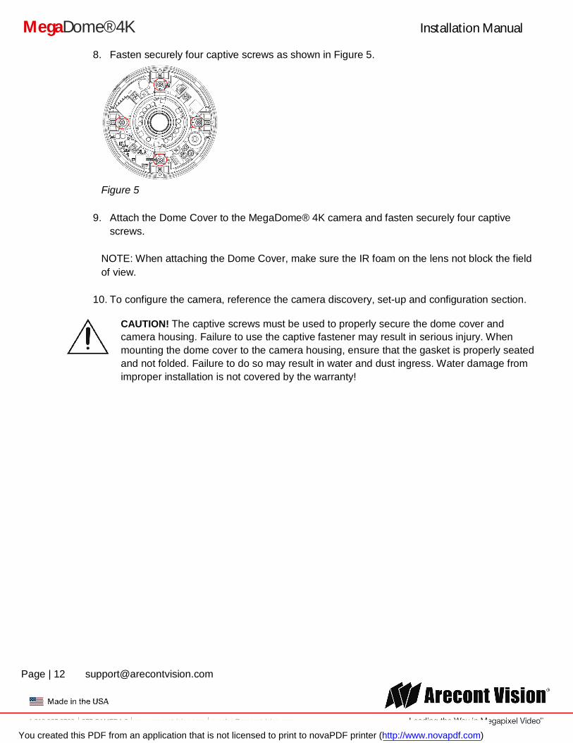
8. Fasten securely four captive screws as shown in Figure 5.
Figure 5
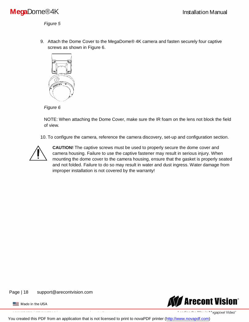
9. Attach the Dome Cover to the MegaDome® 4K camera and fasten securely four captive screws.
NOTE: When attaching the Dome Cover, make sure the IR foam on the lens not block the field of view.
10. To configure the camera, reference the camera discovery, set-up and configuration section.
CAUTION! The captive screws must be used to properly secure the dome cover and camera housing. Failure to use the captive fastener may result in serious injury. When mounting the dome cover to the camera housing, ensure that the gasket is properly seated and not folded. Failure to do so may result in water and dust ingress. Water damage from improper installation is not covered by the warranty!
You created this PDF from an application that is not licensed to print to novaPDF printer (http://www.novapdf.com)
Installation Manual
Page | 13 [email protected]
+1.818.937.0700 877.CAMERA.8 www.arecontvision.com [email protected]
MegaDome® 4K
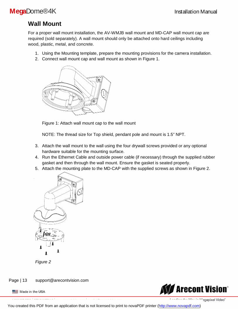
Wall Mount For a proper wall mount installation, the AV-WMJB wall mount and MD-CAP wall mount cap are required (sold separately). A wall mount should only be attached onto hard ceilings including wood, plastic, metal, and concrete.
1. Using the Mounting template, prepare the mounting provisions for the camera installation. 2. Connect wall mount cap and wall mount as shown in Figure 1.
Figure 1: Attach wall mount cap to the wall mount NOTE: The thread size for Top shield, pendant pole and mount is 1.5” NPT.
3. Attach the wall mount to the wall using the four drywall screws provided or any optional hardware suitable for the mounting surface.
4. Run the Ethernet Cable and outside power cable (if necessary) through the supplied rubber gasket and then through the wall mount. Ensure the gasket is seated properly.
5. Attach the mounting plate to the MD-CAP with the supplied screws as shown in Figure 2.
Figure 2
You created this PDF from an application that is not licensed to print to novaPDF printer (http://www.novapdf.com)
Installation Manual
Page | 14 [email protected]
+1.818.937.0700 877.CAMERA.8 www.arecontvision.com [email protected]
MegaDome® 4K
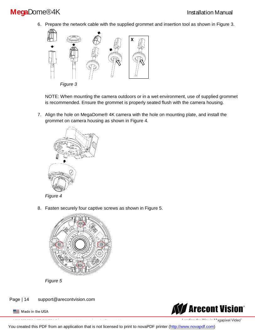
6. Prepare the network cable with the supplied grommet and insertion tool as shown in Figure 3.
Figure 3
NOTE: When mounting the camera outdoors or in a wet environment, use of supplied grommet is recommended. Ensure the grommet is properly seated flush with the camera housing.
7. Align the hole on MegaDome® 4K camera with the hole on mounting plate, and install the grommet on camera housing as shown in Figure 4.
Figure 4
8. Fasten securely four captive screws as shown in Figure 5.
Figure 5
You created this PDF from an application that is not licensed to print to novaPDF printer (http://www.novapdf.com)
Installation Manual
Page | 15 [email protected]
+1.818.937.0700 877.CAMERA.8 www.arecontvision.com [email protected]
MegaDome® 4K
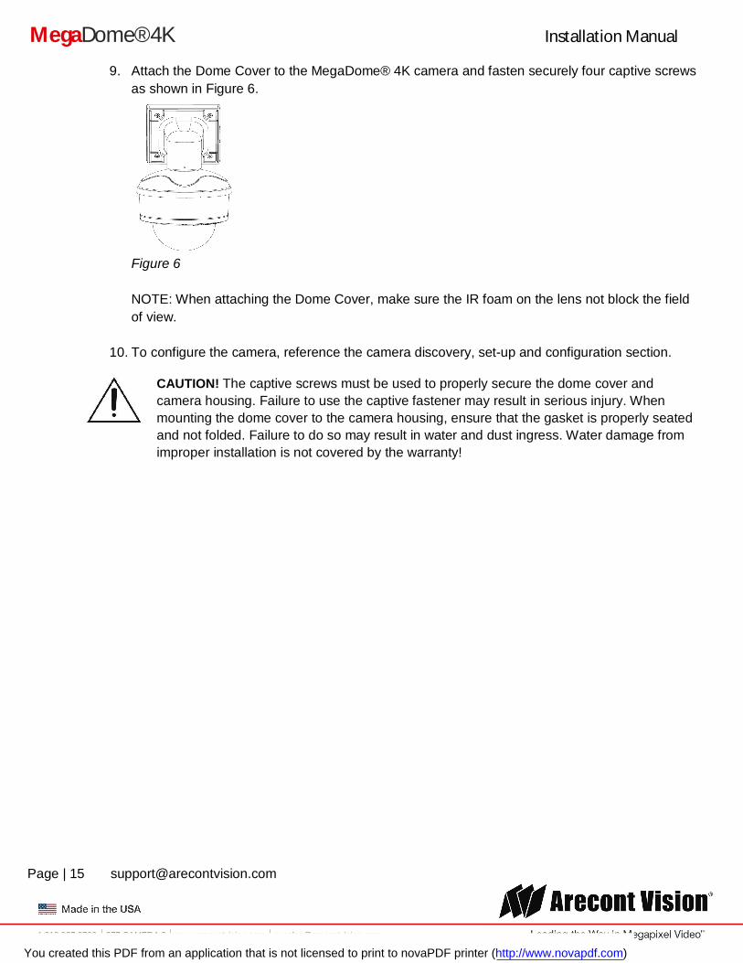
9. Attach the Dome Cover to the MegaDome® 4K camera and fasten securely four captive screws as shown in Figure 6.
Figure 6 NOTE: When attaching the Dome Cover, make sure the IR foam on the lens not block the field of view.
10. To configure the camera, reference the camera discovery, set-up and configuration section.
CAUTION! The captive screws must be used to properly secure the dome cover and camera housing. Failure to use the captive fastener may result in serious injury. When mounting the dome cover to the camera housing, ensure that the gasket is properly seated and not folded. Failure to do so may result in water and dust ingress. Water damage from improper installation is not covered by the warranty!
You created this PDF from an application that is not licensed to print to novaPDF printer (http://www.novapdf.com)
Installation Manual
Page | 16 [email protected]
+1.818.937.0700 877.CAMERA.8 www.arecontvision.com [email protected]
MegaDome® 4K
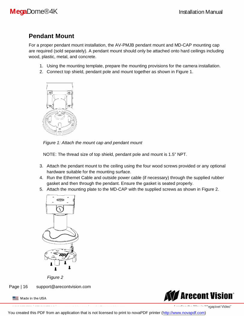
Pendant Mount For a proper pendant mount installation, the AV-PMJB pendant mount and MD-CAP mounting cap are required (sold separately). A pendant mount should only be attached onto hard ceilings including wood, plastic, metal, and concrete.
1. Using the mounting template, prepare the mounting provisions for the camera installation. 2. Connect top shield, pendant pole and mount together as shown in Figure 1.
Figure 1: Attach the mount cap and pendant mount NOTE: The thread size of top shield, pendant pole and mount is 1.5” NPT.
3. Attach the pendant mount to the ceiling using the four wood screws provided or any optional hardware suitable for the mounting surface.
4. Run the Ethernet Cable and outside power cable (if necessary) through the supplied rubber gasket and then through the pendant. Ensure the gasket is seated properly.
5. Attach the mounting plate to the MD-CAP with the supplied screws as shown in Figure 2.
Figure 2
You created this PDF from an application that is not licensed to print to novaPDF printer (http://www.novapdf.com)
Installation Manual
Page | 17 [email protected]
+1.818.937.0700 877.CAMERA.8 www.arecontvision.com [email protected]
MegaDome® 4K
6. Prepare the network cable with the supplied grommet and insertion tool as shown in Figure 3.
Figure 3 NOTE: When mounting the camera outdoors or in a wet environment, use of supplied grommet is recommended. Ensure the grommet is properly seated flush with the camera housing.
7. Align the hole on MegaDome® 4K camera with the hole on mounting plate, and install the grommet on camera housing as shown in Figure 4.
Figure 4
8. Fasten securely four captive screws as shown in Figure 5.
You created this PDF from an application that is not licensed to print to novaPDF printer (http://www.novapdf.com)
Installation Manual
Page | 18 [email protected]
+1.818.937.0700 877.CAMERA.8 www.arecontvision.com [email protected]
MegaDome® 4K
Figure 5
9. Attach the Dome Cover to the MegaDome® 4K camera and fasten securely four captive screws as shown in Figure 6.
Figure 6 NOTE: When attaching the Dome Cover, make sure the IR foam on the lens not block the field of view.
10. To configure the camera, reference the camera discovery, set-up and configuration section.
CAUTION! The captive screws must be used to properly secure the dome cover and camera housing. Failure to use the captive fastener may result in serious injury. When mounting the dome cover to the camera housing, ensure that the gasket is properly seated and not folded. Failure to do so may result in water and dust ingress. Water damage from improper installation is not covered by the warranty!
You created this PDF from an application that is not licensed to print to novaPDF printer (http://www.novapdf.com)
Installation Manual
Page | 19 [email protected]
+1.818.937.0700 877.CAMERA.8 www.arecontvision.com [email protected]
MegaDome® 4K
+1.818.937.0700 877.CAMERA.8 www.arecontvision.com [email protected]
Pole Mount For a pole mount installation, the AV-WMJB wall mount, AV-PMA pole mount, and MD-CAP mount cap are required (sold separately). A pole mount should only be attached onto hard ceilings including wood, plastic, metal, and concrete.
1. Using the mounting template, prepare the mounting provisions for the camera installation.
2. Connect the wall mount cap and wall mount.
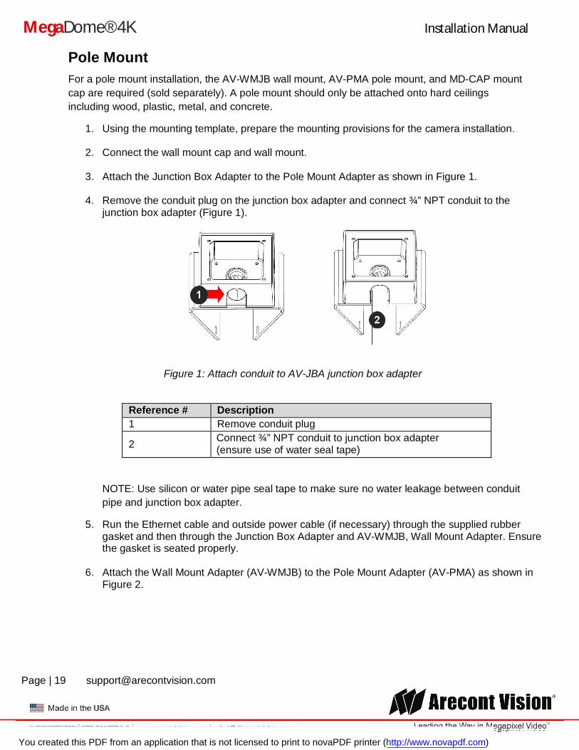
3. Attach the Junction Box Adapter to the Pole Mount Adapter as shown in Figure 1.
4. Remove the conduit plug on the junction box adapter and connect ¾” NPT conduit to the junction box adapter (Figure 1).
Figure 1: Attach conduit to AV-JBA junction box adapter
Reference # Description 1 Remove conduit plug
2 Connect ¾” NPT conduit to junction box adapter (ensure use of water seal tape)
NOTE: Use silicon or water pipe seal tape to make sure no water leakage between conduit pipe and junction box adapter.
5. Run the Ethernet cable and outside power cable (if necessary) through the supplied rubber gasket and then through the Junction Box Adapter and AV-WMJB, Wall Mount Adapter. Ensure the gasket is seated properly.
6. Attach the Wall Mount Adapter (AV-WMJB) to the Pole Mount Adapter (AV-PMA) as shown in Figure 2.
You created this PDF from an application that is not licensed to print to novaPDF printer (http://www.novapdf.com)
Installation Manual
Page | 20 [email protected]
+1.818.937.0700 877.CAMERA.8 www.arecontvision.com [email protected]
MegaDome® 4K
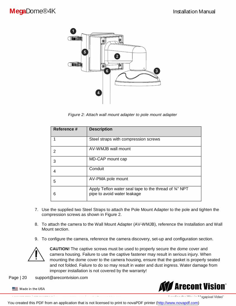
Figure 2: Attach wall mount adapter to pole mount adapter
Reference # Description
1 Steel straps with compression screws
2 AV-WMJB wall mount
3 MD-CAP mount cap
4 Conduit
5 AV-PMA pole mount
6 Apply Teflon water seal tape to the thread of ¾” NPT pipe to avoid water leakage
7. Use the supplied two Steel Straps to attach the Pole Mount Adapter to the pole and tighten the compression screws as shown in Figure 2.
8. To attach the camera to the Wall Mount Adapter (AV-WMJB), reference the Installation and Wall Mount section.
9. To configure the camera, reference the camera discovery, set-up and configuration section.
CAUTION! The captive screws must be used to properly secure the dome cover and camera housing. Failure to use the captive fastener may result in serious injury. When mounting the dome cover to the camera housing, ensure that the gasket is properly seated and not folded. Failure to do so may result in water and dust ingress. Water damage from improper installation is not covered by the warranty!
You created this PDF from an application that is not licensed to print to novaPDF printer (http://www.novapdf.com)
Installation Manual
Page | 21 [email protected]
+1.818.937.0700 877.CAMERA.8 www.arecontvision.com [email protected]
MegaDome® 4K
Corner Mount For a corner mount installation, the AV-WMJB wall mount, AV-CRMA corner mount, and MD-CAP mount cap are required (sold separately). A corner mount should only be attached onto hard corner surfaces including wood, plastic, metal, and concrete.
1. Using the Mounting template, prepare the mounting provisions for the camera installation.
2. Connect the wall mount cap and wall mount.
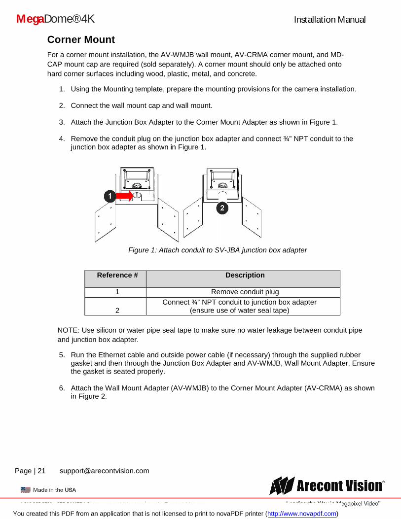
3. Attach the Junction Box Adapter to the Corner Mount Adapter as shown in Figure 1.
4. Remove the conduit plug on the junction box adapter and connect ¾” NPT conduit to the junction box adapter as shown in Figure 1.
Figure 1: Attach conduit to SV-JBA junction box adapter
Reference # Description
1 Remove conduit plug
2 Connect ¾” NPT conduit to junction box adapter
(ensure use of water seal tape)
NOTE: Use silicon or water pipe seal tape to make sure no water leakage between conduit pipe and junction box adapter.
5. Run the Ethernet cable and outside power cable (if necessary) through the supplied rubber gasket and then through the Junction Box Adapter and AV-WMJB, Wall Mount Adapter. Ensure the gasket is seated properly.
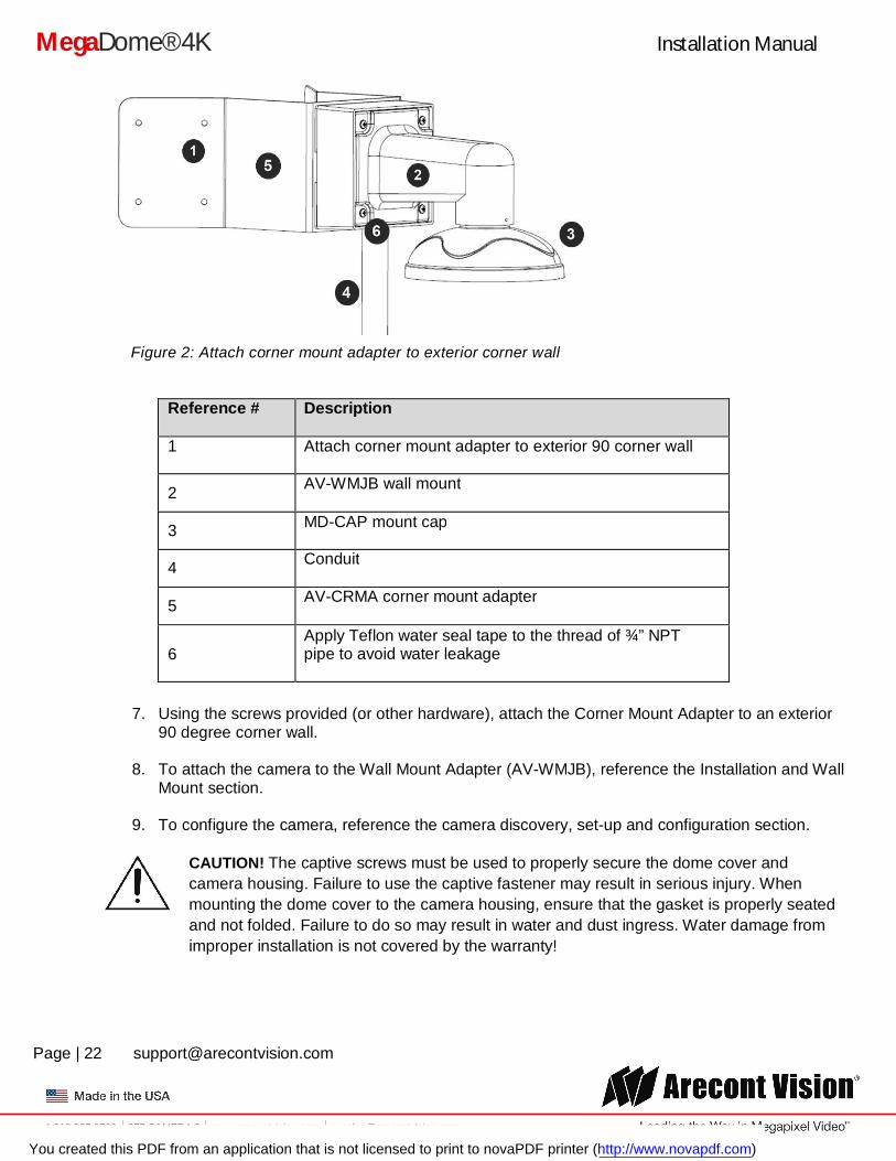
6. Attach the Wall Mount Adapter (AV-WMJB) to the Corner Mount Adapter (AV-CRMA) as shown in Figure 2.
You created this PDF from an application that is not licensed to print to novaPDF printer (http://www.novapdf.com)
Installation Manual
Page | 22 [email protected]
+1.818.937.0700 877.CAMERA.8 www.arecontvision.com [email protected]
MegaDome® 4K
Figure 2: Attach corner mount adapter to exterior corner wall
Reference # Description
1 Attach corner mount adapter to exterior 90 corner wall
2 AV-WMJB wall mount
3 MD-CAP mount cap
4 Conduit
5 AV-CRMA corner mount adapter
6 Apply Teflon water seal tape to the thread of ¾” NPT pipe to avoid water leakage
7. Using the screws provided (or other hardware), attach the Corner Mount Adapter to an exterior 90 degree corner wall.
8. To attach the camera to the Wall Mount Adapter (AV-WMJB), reference the Installation and Wall Mount section.
9. To configure the camera, reference the camera discovery, set-up and configuration section.
CAUTION! The captive screws must be used to properly secure the dome cover and camera housing. Failure to use the captive fastener may result in serious injury. When mounting the dome cover to the camera housing, ensure that the gasket is properly seated and not folded. Failure to do so may result in water and dust ingress. Water damage from improper installation is not covered by the warranty!
You created this PDF from an application that is not licensed to print to novaPDF printer (http://www.novapdf.com)
Installation Manual
Page | 23 [email protected]
+1.818.937.0700 877.CAMERA.8 www.arecontvision.com [email protected]
MegaDome® 4K
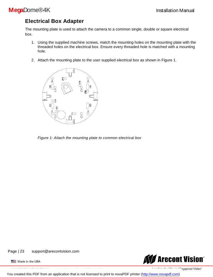
Electrical Box Adapter The mounting plate is used to attach the camera to a common single, double or square electrical box.
1. Using the supplied machine screws, match the mounting holes on the mounting plate with the threaded holes on the electrical box. Ensure every threaded hole is matched with a mounting hole.
2. Attach the mounting plate to the user supplied electrical box as shown in Figure 1.
Figure 1: Attach the mounting plate to common electrical box
You created this PDF from an application that is not licensed to print to novaPDF printer (http://www.novapdf.com)
Installation Manual
Page | 24 [email protected]
+1.818.937.0700 877.CAMERA.8 www.arecontvision.com [email protected]
MegaDome® 4K
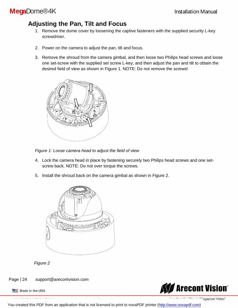
Adjusting the Pan, Tilt and Focus 1. Remove the dome cover by loosening the captive fasteners with the supplied security L-key
screwdriver.
2. Power on the camera to adjust the pan, tilt and focus.
3. Remove the shroud from the camera gimbal, and then loose two Philips head screws and loose one set-screw with the supplied set screw L-key, and then adjust the pan and tilt to obtain the desired field of view as shown in Figure 1. NOTE: Do not remove the screws!
Figure 1: Loose camera head to adjust the field of view
4. Lock the camera head in place by fastening securely two Philips head screws and one set-screw back. NOTE: Do not over torque the screws.
5. Install the shroud back on the camera gimbal as shown in Figure 2.
Figure 2
You created this PDF from an application that is not licensed to print to novaPDF printer (http://www.novapdf.com)
Installation Manual
Page | 25 [email protected]
+1.818.937.0700 877.CAMERA.8 www.arecontvision.com [email protected]
MegaDome® 4K
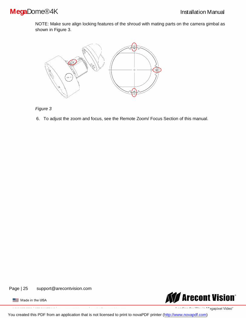
NOTE: Make sure align locking features of the shroud with mating parts on the camera gimbal as shown in Figure 3.
Figure 3
6. To adjust the zoom and focus, see the Remote Zoom/ Focus Section of this manual.
You created this PDF from an application that is not licensed to print to novaPDF printer (http://www.novapdf.com)
Installation Manual
Page | 26 [email protected]
+1.818.937.0700 877.CAMERA.8 www.arecontvision.com [email protected]
MegaDome® 4K
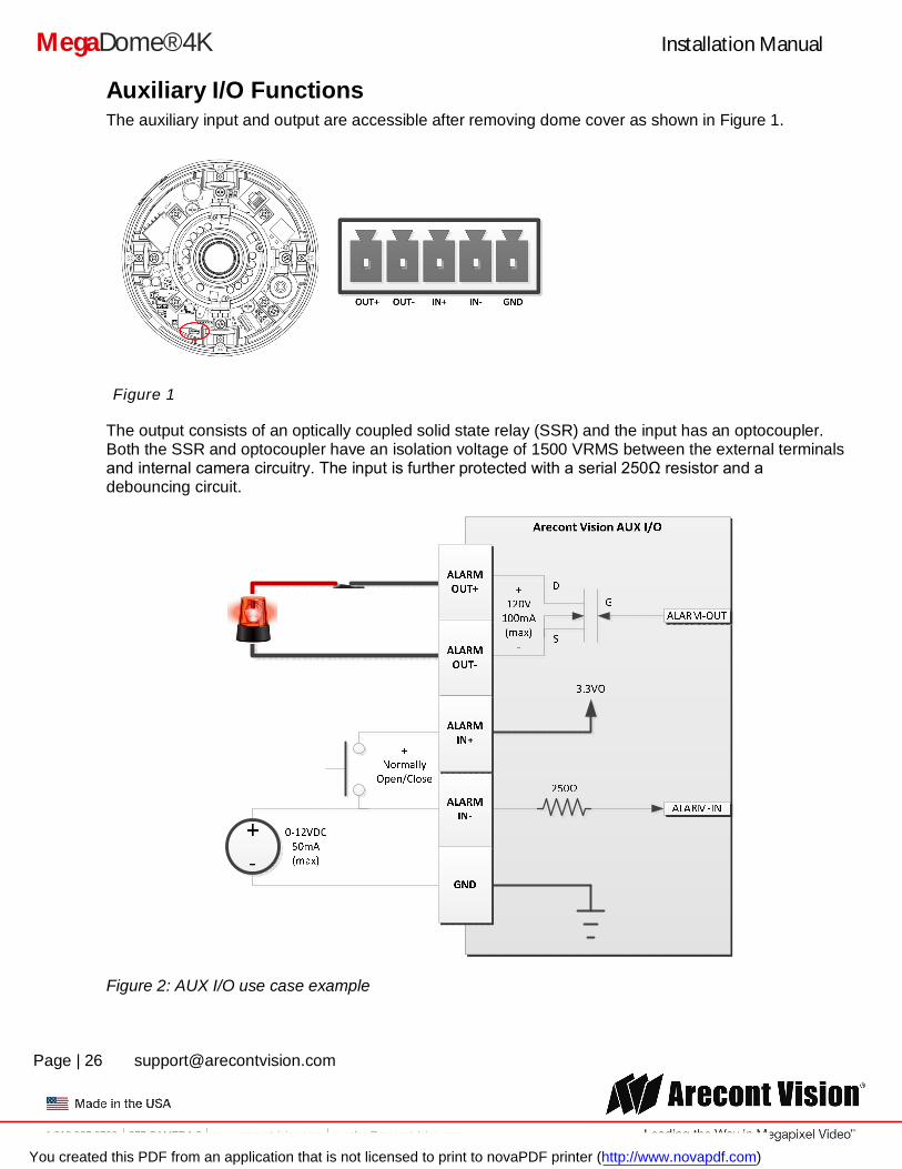
Auxiliary I/O Functions The auxiliary input and output are accessible after removing dome cover as shown in Figure 1.
Figure 1
The output consists of an optically coupled solid state relay (SSR) and the input has an optocoupler. Both the SSR and optocoupler have an isolation voltage of 1500 VRMS between the external terminals and internal camera circuitry. The input is further protected with a serial 250Ω resistor and a debouncing circuit.
Figure 2: AUX I/O use case example
You created this PDF from an application that is not licensed to print to novaPDF printer (http://www.novapdf.com)
Installation Manual
Page | 27 [email protected]
+1.818.937.0700 877.CAMERA.8 www.arecontvision.com [email protected]
MegaDome® 4K
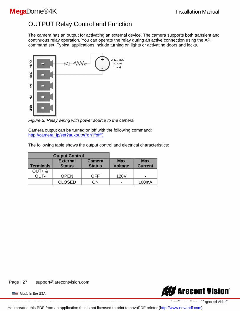
OUTPUT Relay Control and Function The camera has an output for activating an external device. The camera supports both transient and continuous relay operation. You can operate the relay during an active connection using the API command set. Typical applications include turning on lights or activating doors and locks.
IN+
IN-
GN
DO
UT+
OU
T-
Figure 3: Relay wiring with power source to the camera
Camera output can be turned on|off with the following command: http://camera_ip/set?auxout=(“on”|“off”) The following table shows the output control and electrical characteristics:
Output Control
Terminals External Status
Camera Status
Max Voltage
Max Current
OUT+ & OUT- OPEN OFF 120V -
CLOSED ON - 100mA
You created this PDF from an application that is not licensed to print to novaPDF printer (http://www.novapdf.com)
Installation Manual
Page | 28 [email protected]
+1.818.937.0700 877.CAMERA.8 www.arecontvision.com [email protected]
MegaDome® 4K
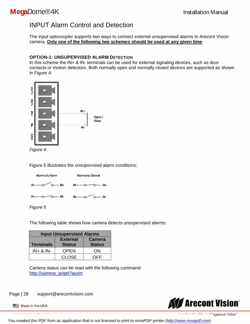
INPUT Alarm Control and Detection
The input optocoupler supports two ways to connect external unsupervised alarms to Arecont Vision camera. Only one of the following two schemes should be used at any given time. OPTION-1: UNSUPERVISED ALARM DETECTION In this scheme the IN+ & IN- terminals can be used for external signaling devices, such as door contacts or motion detectors. Both normally open and normally closed devices are supported as shown in Figure 4:
Figure 4
Figure 5 illustrates the unsupervised alarm conditions:
Figure 5 The following table shows how camera detects unsupervised alarms:
Input Unsupervised Alarms
Terminals External Status
Camera Status
IN+ & IN- OPEN ON CLOSE OFF
Camera status can be read with the following command: http://camera_ip/get?auxin
You created this PDF from an application that is not licensed to print to novaPDF printer (http://www.novapdf.com)
Installation Manual
Page | 29 [email protected]
+1.818.937.0700 877.CAMERA.8 www.arecontvision.com [email protected]
MegaDome® 4K
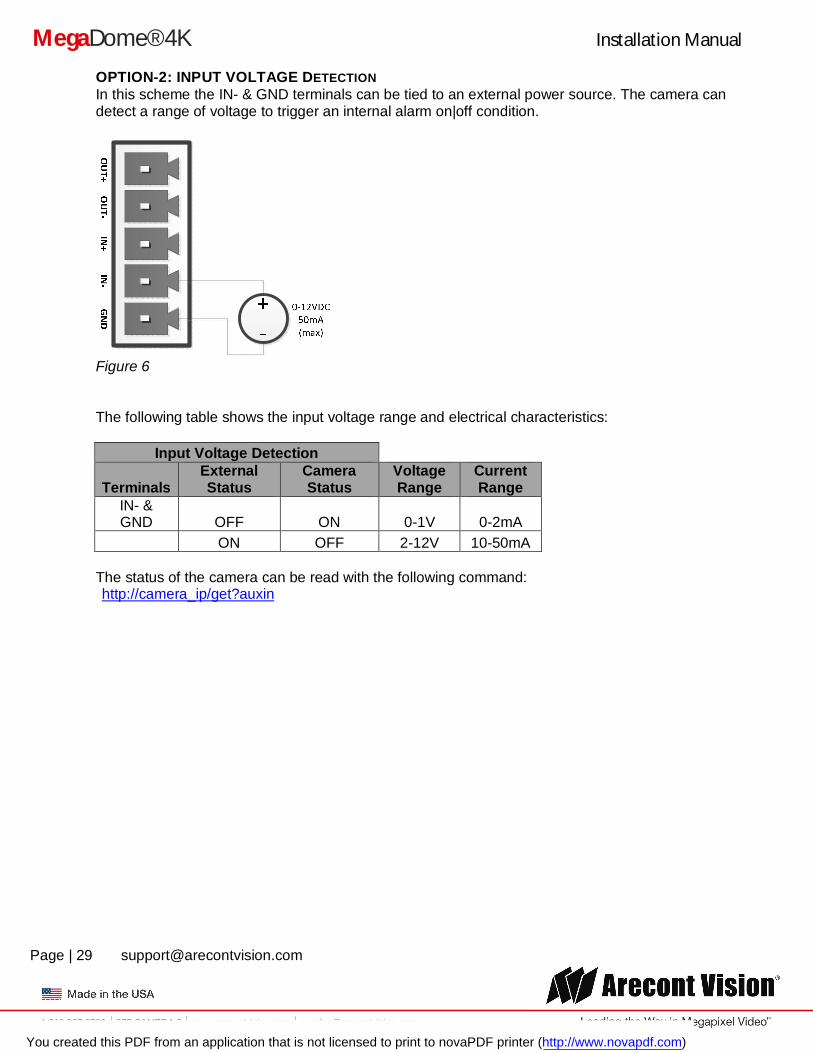
OPTION-2: INPUT VOLTAGE DETECTION In this scheme the IN- & GND terminals can be tied to an external power source. The camera can detect a range of voltage to trigger an internal alarm on|off condition.
Figure 6
The following table shows the input voltage range and electrical characteristics:
Input Voltage Detection
Terminals External Status
Camera Status
Voltage Range
Current Range
IN- & GND OFF ON 0-1V 0-2mA
ON OFF 2-12V 10-50mA The status of the camera can be read with the following command: http://camera_ip/get?auxin
You created this PDF from an application that is not licensed to print to novaPDF printer (http://www.novapdf.com)
Installation Manual
Page | 30 [email protected]
+1.818.937.0700 877.CAMERA.8 www.arecontvision.com [email protected]
MegaDome® 4K
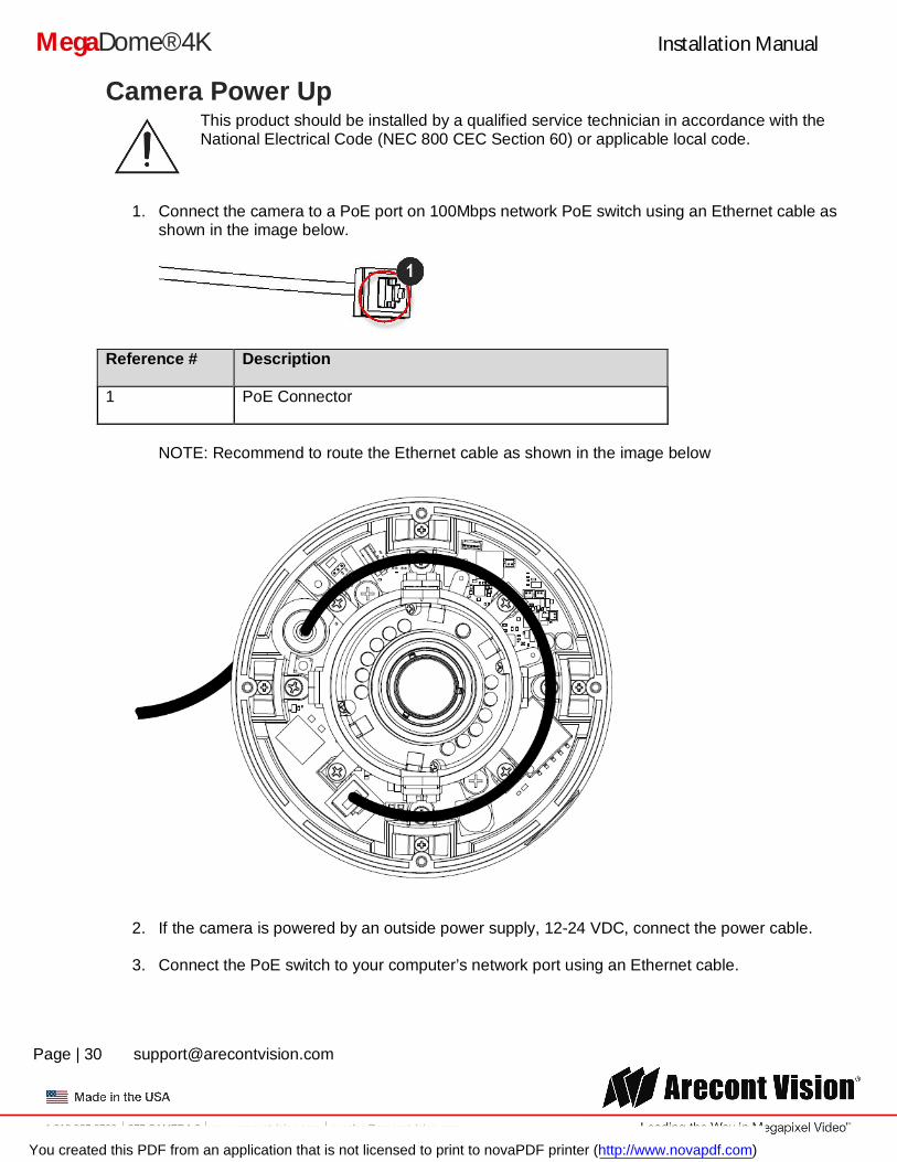
Camera Power Up This product should be installed by a qualified service technician in accordance with the National Electrical Code (NEC 800 CEC Section 60) or applicable local code.
1. Connect the camera to a PoE port on 100Mbps network PoE switch using an Ethernet cable as shown in the image below.
Reference # Description
1 PoE Connector
NOTE: Recommend to route the Ethernet cable as shown in the image below
2. If the camera is powered by an outside power supply, 12-24 VDC, connect the power cable.
3. Connect the PoE switch to your computer’s network port using an Ethernet cable.
You created this PDF from an application that is not licensed to print to novaPDF printer (http://www.novapdf.com)
Installation Manual
Page | 31 [email protected]
+1.818.937.0700 877.CAMERA.8 www.arecontvision.com [email protected]
MegaDome® 4K
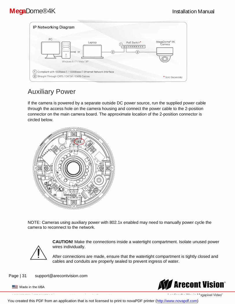
Auxiliary Power
If the camera is powered by a separate outside DC power source, run the supplied power cable through the access hole on the camera housing and connect the power cable to the 2-position connector on the main camera board. The approximate location of the 2-position connector is circled below.
NOTE: Cameras using auxiliary power with 802.1x enabled may need to manually power cycle the camera to reconnect to the network.
CAUTION! Make the connections inside a watertight compartment. Isolate unused power wires individually. After connections are made, ensure that the watertight compartment is tightly closed and cables and conduits are properly sealed to prevent ingress of water.
You created this PDF from an application that is not licensed to print to novaPDF printer (http://www.novapdf.com)
Installation Manual
Page | 32 [email protected]
+1.818.937.0700 877.CAMERA.8 www.arecontvision.com [email protected]
MegaDome® 4K
NOTE: A yellow LED on the rear of the camera illuminates after a few seconds. The flashing yellow LED indicates that a link to your computer has been established. A green LED will blink when the camera has been accessed.
LED Status Description
Yellow Flashing Link has been established.
Solid Normal Operation.
Green Flashing Camera has been accessed. Normal operation.
Solid N/A
None None No Connection.
NOTE: Wiring methods shall be in accordance with the National Electrical Code/NFPA 70/ANSI, and with all local codes and authorities having jurisdiction. Wiring should be UL Listed and/or Recognized wire suitable for the application.
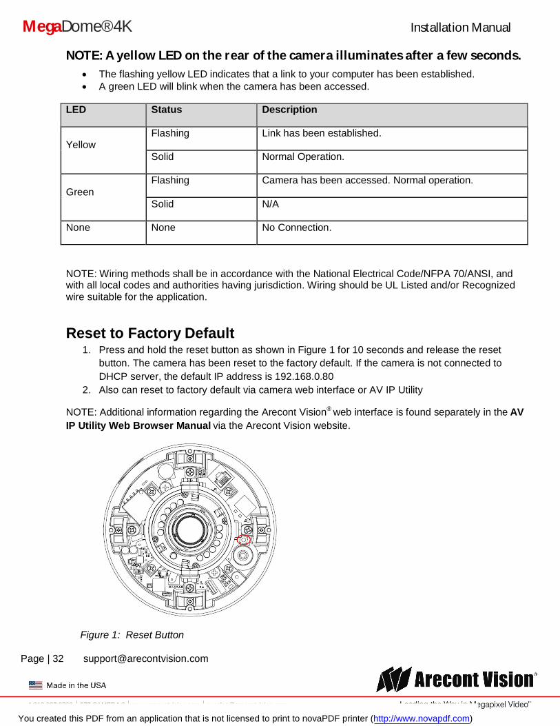
Reset to Factory Default 1. Press and hold the reset button as shown in Figure 1 for 10 seconds and release the reset
button. The camera has been reset to the factory default. If the camera is not connected to DHCP server, the default IP address is 192.168.0.80
2. Also can reset to factory default via camera web interface or AV IP Utility
NOTE: Additional information regarding the Arecont Vision® web interface is found separately in the AV IP Utility Web Browser Manual via the Arecont Vision website.
Figure 1: Reset Button
You created this PDF from an application that is not licensed to print to novaPDF printer (http://www.novapdf.com)
Installation Manual
Page | 33 [email protected]
+1.818.937.0700 877.CAMERA.8 www.arecontvision.com [email protected]
MegaDome® 4K
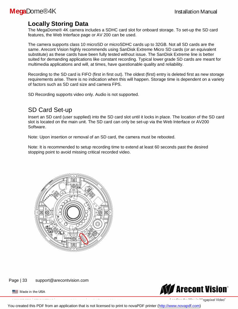
Locally Storing Data The MegaDome® 4K camera includes a SDHC card slot for onboard storage. To set-up the SD card features, the Web Interface page or AV 200 can be used.
The camera supports class 10 microSD or microSDHC cards up to 32GB. Not all SD cards are the same. Arecont Vision highly recommends using SanDisk Extreme Micro SD cards (or an equivalent substitute) as these cards have been fully tested without issue. The SanDisk Extreme line is better suited for demanding applications like constant recording. Typical lower grade SD cards are meant for multimedia applications and will, at times, have questionable quality and reliability.
Recording to the SD card is FIFO (first in first out). The oldest (first) entry is deleted first as new storage requirements arise. There is no indication when this will happen. Storage time is dependent on a variety of factors such as SD card size and camera FPS.
SD Recording supports video only. Audio is not supported.
SD Card Set-up Insert an SD card (user supplied) into the SD card slot until it locks in place. The location of the SD card slot is located on the main unit. The SD card can only be set-up via the Web Interface or AV200 Software.
Note: Upon insertion or removal of an SD card, the camera must be rebooted.
Note: It is recommended to setup recording time to extend at least 60 seconds past the desired stopping point to avoid missing critical recorded video.
You created this PDF from an application that is not licensed to print to novaPDF printer (http://www.novapdf.com)
Installation Manual
Page | 34 [email protected]
+1.818.937.0700 877.CAMERA.8 www.arecontvision.com [email protected]
MegaDome® 4K
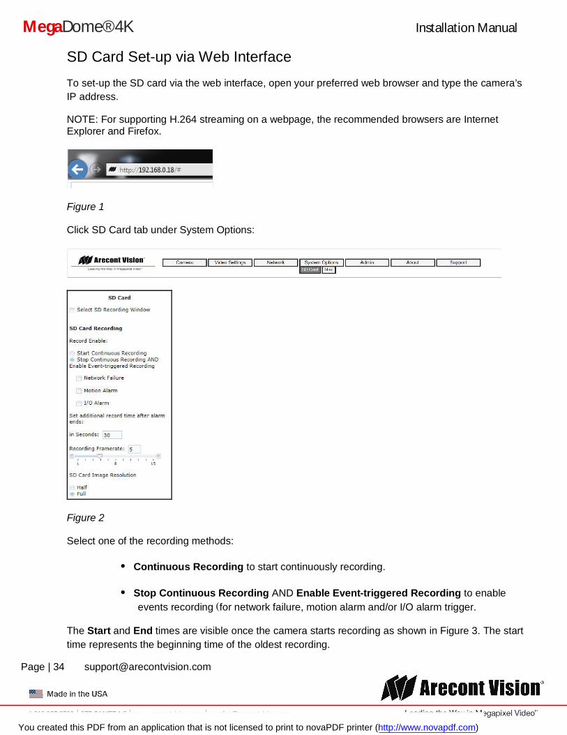
SD Card Set-up via Web Interface
To set-up the SD card via the web interface, open your preferred web browser and type the camera’s IP address.
NOTE: For supporting H.264 streaming on a webpage, the recommended browsers are Internet Explorer and Firefox.
Figure 1
Click SD Card tab under System Options:
Figure 2
Select one of the recording methods:
Continuous Recording to start continuously recording.
Stop Continuous Recording AND Enable Event-triggered Recording to enable events recording for network failure, motion alarm and/or I/O alarm trigger.
The Start and End times are visible once the camera starts recording as shown in Figure 3. The start time represents the beginning time of the oldest recording.
You created this PDF from an application that is not licensed to print to novaPDF printer (http://www.novapdf.com)
Installation Manual
Page | 35 [email protected]
+1.818.937.0700 877.CAMERA.8 www.arecontvision.com [email protected]
MegaDome® 4K
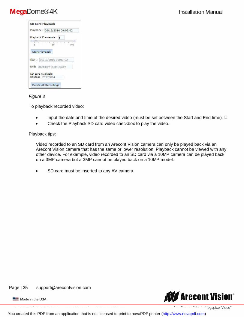
Figure 3
To playback recorded video:
Input the date and time of the desired video (must be set between the Start and End time). Check the Playback SD card video checkbox to play the video.
Playback tips:
Video recorded to an SD card from an Arecont Vision camera can only be played back via an Arecont Vision camera that has the same or lower resolution. Playback cannot be viewed with any other device. For example, video recorded to an SD card via a 10MP camera can be played back on a 3MP camera but a 3MP cannot be played back on a 10MP model.
SD card must be inserted to any AV camera.
You created this PDF from an application that is not licensed to print to novaPDF printer (http://www.novapdf.com)
Installation Manual
Page | 36 [email protected]
+1.818.937.0700 877.CAMERA.8 www.arecontvision.com [email protected]
MegaDome® 4K
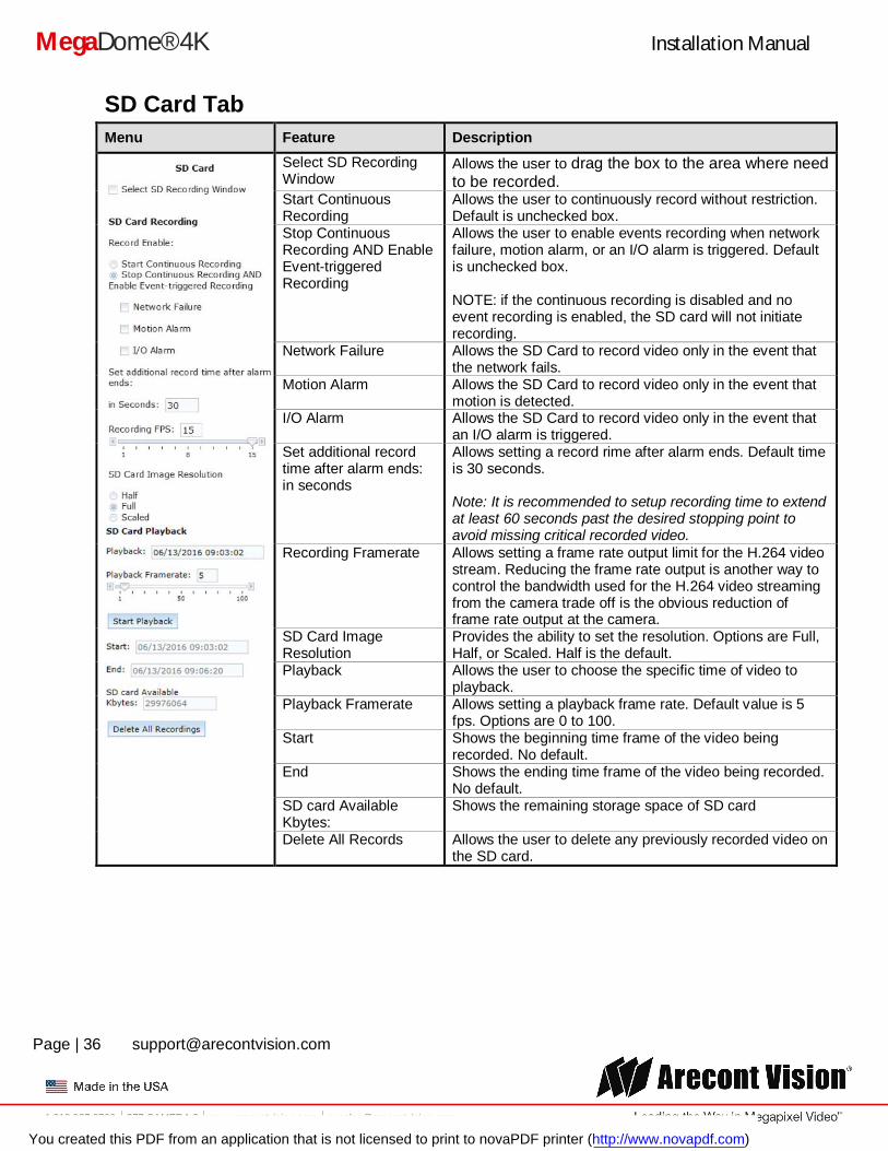
SD Card Tab Menu Feature Description
Select SD Recording Window
Allows the user to drag the box to the area where need to be recorded.
Start Continuous Recording
Allows the user to continuously record without restriction. Default is unchecked box.
Stop Continuous Recording AND Enable Event-triggered Recording
Allows the user to enable events recording when network failure, motion alarm, or an I/O alarm is triggered. Default is unchecked box. NOTE: if the continuous recording is disabled and no event recording is enabled, the SD card will not initiate recording.
Network Failure Allows the SD Card to record video only in the event that the network fails.
Motion Alarm Allows the SD Card to record video only in the event that motion is detected.
I/O Alarm Allows the SD Card to record video only in the event that an I/O alarm is triggered.
Set additional record time after alarm ends: in seconds
Allows setting a record rime after alarm ends. Default time is 30 seconds. Note: It is recommended to setup recording time to extend at least 60 seconds past the desired stopping point to avoid missing critical recorded video.
Recording Framerate Allows setting a frame rate output limit for the H.264 video stream. Reducing the frame rate output is another way to control the bandwidth used for the H.264 video streaming from the camera trade off is the obvious reduction of frame rate output at the camera.
SD Card Image Resolution
Provides the ability to set the resolution. Options are Full, Half, or Scaled. Half is the default.
Playback Allows the user to choose the specific time of video to playback.
Playback Framerate Allows setting a playback frame rate. Default value is 5 fps. Options are 0 to 100.
Start Shows the beginning time frame of the video being recorded. No default.
End Shows the ending time frame of the video being recorded. No default.
SD card Available Kbytes:
Shows the remaining storage space of SD card
Delete All Records Allows the user to delete any previously recorded video on the SD card.
You created this PDF from an application that is not licensed to print to novaPDF printer (http://www.novapdf.com)
Installation Manual
Page | 37 [email protected]
+1.818.937.0700 877.CAMERA.8 www.arecontvision.com [email protected]
MegaDome® 4K
System Requirements
Computer with Windows XP/Vista/7 operating system, network access, and Microsoft Internet Explorer web browser version 9.0 or later (32-bit).
Camera Discovery, Setup, and Configuration For camera discovery and setup, the AV IP Utility is recommended. The software can be found on the CD included with your camera or at: http://www.arecontvision.com/softwares.php.
The AV IP Utility has the ability to provide multiple discovery options, including broadcast and multicast, check the status of a camera, change camera settings, import and export camera settings via a .csv file, and update firmware and/or hardware from virtually anywhere with a network connection.
Whether used for large installations that require an update to multiple settings, or smaller installations where only one camera needs changed, the AV IP Utility tool is efficient and convenient for mass or single camera uploads.
The AV IP Utility tool is compatible with all Arecont Vision® megapixel cameras. The user manual for the software is included on the CD that came with your camera or available on our website.
Network Protocols The Arecont Vision MegaDome® 4K cameras support RTSP, RTP/TCP, RTP/UDP, HTTP, HTTPs, DHCP, TFTP, QoS, IP version 4 (IPv4), IP version 6 (IPv6), and 802.1x.
RTSP – Cameras communicate with video management systems over Real Time Streaming Protocol. Do not change the RTSP port unless you are sure your VMS does not use the default setting.
RTP/TCP – The Real-time Protocol/Transmission Control Protocol is best suited for applications that require high reliability, and transmission time is relatively less critical.
RTP/UDP – The Real-time Protocol/User Datagram Protocol is used for live unicast video, especially when it is important to always have an up-to-date video stream, even if some images are dropped.
HTTP – The Hypertext Transfer Protocol is an application protocol for distributed, collaborative, hypermedia information systems.
HTTPs – Hypertext Transfer Protocol Secure: encrypts and authenticates communication between Web server and browser.
DHCP – The Dynamic Host Configuration Protocol allows network administrators to centrally manage and automate the assignment of IP addresses. DHCP should only be enabled if using dynamic IP address notification, or if the DHCP can update a DNS server.
TFTP – The Trivial File Transfer Protocol is a simple, lock-step, File Transfer Protocol which allows a client to get from or put a file onto a remote host. TFTP lacks security and most of the advanced features offered by more robust file transfer protocols such as File Transfer Protocol.
You created this PDF from an application that is not licensed to print to novaPDF printer (http://www.novapdf.com)
Installation Manual
Page | 38 [email protected]
+1.818.937.0700 877.CAMERA.8 www.arecontvision.com [email protected]
MegaDome® 4K
QoS – Quality of Service guarantees a certain level of a specified resource to selected traffic on a network. A QoS-aware network prioritizes network traffic and provides a greater network reliability by controlling the amount of bandwidth an application may use.
IPv4 – The MicroDome G2 supports the IPv4 internet-layer protocol for packet-switched internetworking across multiple IP networks. IPv4 uses 32-bit addressing which allows for devices and users on the internet for routing traffic.
IPv6 – This camera supports the IPv6 internet-layer protocol for packet-switched internetworking across multiple IP networks. IPv6 uses 128-bit addresses, which allows for many more devices and users on the internet as well as extra flexibility in allocating addresses and efficiency for routing traffic.
802.1x – The IEEE 802.1x standard provides a general method for authentication and authorization in IEEE-802 networks. Authentication is carried out via the authenticator, which checks the transmitted authentication information using an authentication server and approves or denies access to the offered services (LAN, VLAN or WLAN) accordingly.
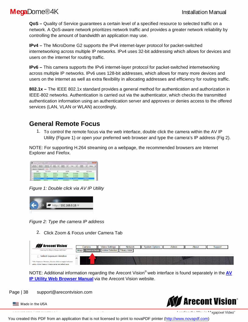
General Remote Focus 1. To control the remote focus via the web interface, double click the camera within the AV IP
Utility (Figure 1) or open your preferred web browser and type the camera’s IP address (Fig 2).
NOTE: For supporting H.264 streaming on a webpage, the recommended browsers are Internet Explorer and Firefox.
Figure 1: Double click via AV IP Utility
Figure 2: Type the camera IP address
2. Click Zoom & Focus under Camera Tab
NOTE: Additional information regarding the Arecont Vision® web interface is found separately in the AV IP Utility Web Browser Manual via the Arecont Vision website.
You created this PDF from an application that is not licensed to print to novaPDF printer (http://www.novapdf.com)
Installation Manual
Page | 39 [email protected]
+1.818.937.0700 877.CAMERA.8 www.arecontvision.com [email protected]
MegaDome® 4K
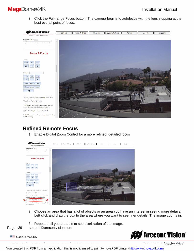
3. Click the Full-range Focus button. The camera begins to autofocus with the lens stopping at the best overall point of focus.
Refined Remote Focus 1. Enable Digital Zoom Control for a more refined, detailed focus
2. Choose an area that has a lot of objects or an area you have an interest in seeing more details. Left click and drag the box to the area where you want to see finer details. The image zooms in.
3. Repeat until you are able to see pixelization of the image.
You created this PDF from an application that is not licensed to print to novaPDF printer (http://www.novapdf.com)
Installation Manual
Page | 40 [email protected]
+1.818.937.0700 877.CAMERA.8 www.arecontvision.com [email protected]
MegaDome® 4K
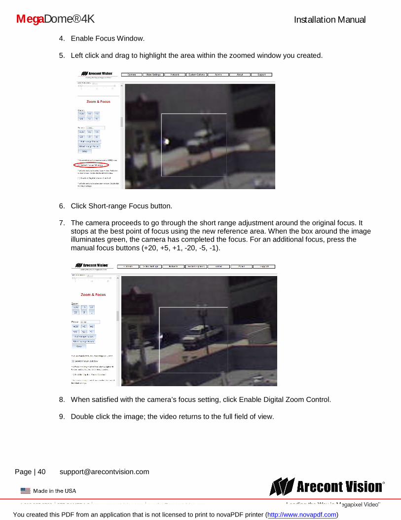
4. Enable Focus Window.
5. Left click and drag to highlight the area within the zoomed window you created.
6. Click Short-range Focus button.
7. The camera proceeds to go through the short range adjustment around the original focus. It stops at the best point of focus using the new reference area. When the box around the image illuminates green, the camera has completed the focus. For an additional focus, press the manual focus buttons (+20, +5, +1, -20, -5, -1).
8. When satisfied with the camera’s focus setting, click Enable Digital Zoom Control.
9. Double click the image; the video returns to the full field of view.
You created this PDF from an application that is not licensed to print to novaPDF printer (http://www.novapdf.com)
Installation Manual
Page | 41 [email protected]
+1.818.937.0700 877.CAMERA.8 www.arecontvision.com [email protected]
MegaDome® 4K
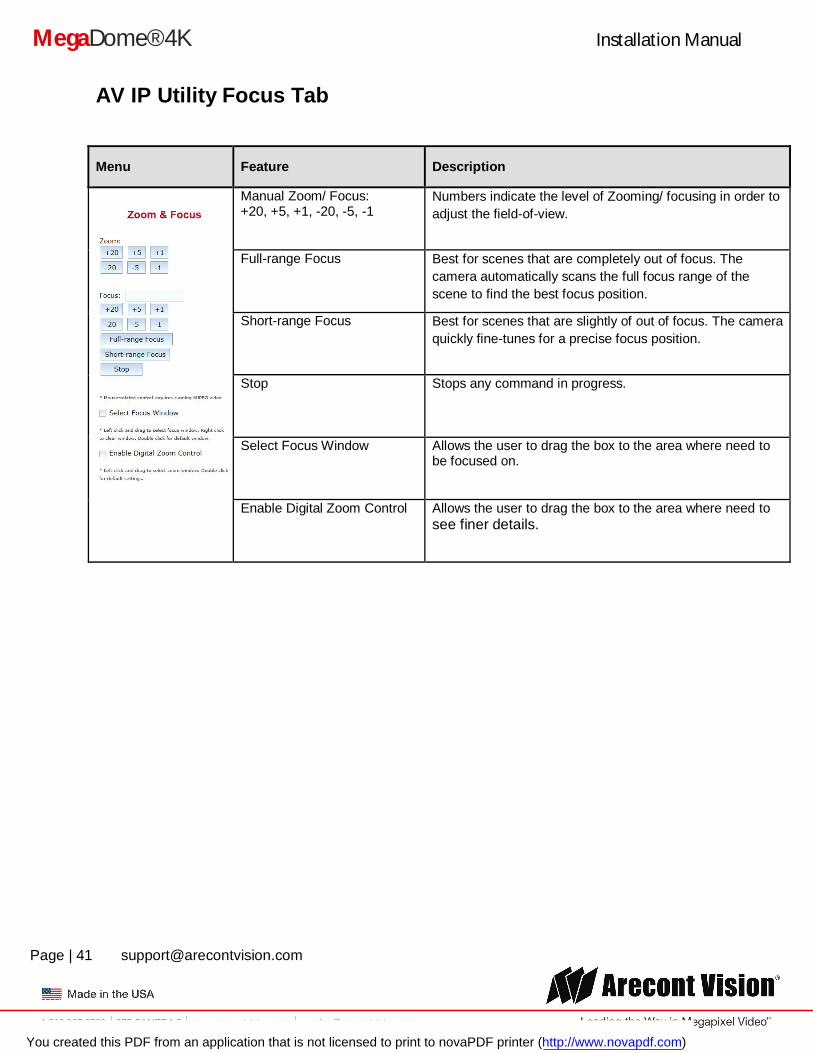
AV IP Utility Focus Tab
Menu Feature Description
Manual Zoom/ Focus: +20, +5, +1, -20, -5, -1
Numbers indicate the level of Zooming/ focusing in order to adjust the field-of-view.
Full-range Focus Best for scenes that are completely out of focus. The camera automatically scans the full focus range of the scene to find the best focus position.
Short-range Focus Best for scenes that are slightly of out of focus. The camera quickly fine-tunes for a precise focus position.
Stop Stops any command in progress.
Select Focus Window Allows the user to drag the box to the area where need to be focused on.
Enable Digital Zoom Control Allows the user to drag the box to the area where need to see finer details.
You created this PDF from an application that is not licensed to print to novaPDF printer (http://www.novapdf.com)
Installation Manual
Page | 42 [email protected]
+1.818.937.0700 877.CAMERA.8 www.arecontvision.com [email protected]
MegaDome® 4K
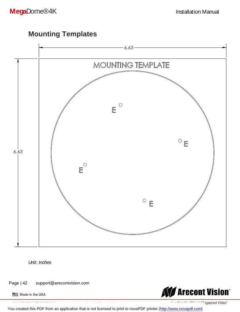
Mounting Templates
Unit: Inches
You created this PDF from an application that is not licensed to print to novaPDF printer (http://www.novapdf.com)
Installation Manual
Page | 43 [email protected]
+1.818.937.0700 877.CAMERA.8 www.arecontvision.com [email protected]
MegaDome® 4K
Support 1. Arecont Vision FAQ Page Located at ArecontVision.com 2. Check the following before you call:
Restore camera to factory default with AV200 or the camera webpage. Upgrade to the latest firmware by visiting ArecontVision.com. Isolate the camera on a dedicated network and test with AV200. Swap the “troubled” camera with a known good camera to see if the problem follows the
camera or stays at the location. 3. Contact Arecont Vision Technical Support one of three ways:
1. Online Portal: Support.ArecontVision.com 2. Phone: 1.818.937.0700 (option #1) 3. Email: [email protected]
4. Use the Arecont Vision software AV IP Utility located on the CD or available for download at our website (www.arecontvision.com) for camera discovery and setup (see Instruction Manual located on the CD or available on our website).
You created this PDF from an application that is not licensed to print to novaPDF printer (http://www.novapdf.com)