md32x0i with windiws faliover clusters hardware installation guide
TRANSCRIPT

5/14/2018 MD32x0i With Windiws Faliover Clusters Hardware Installation Guide - slidepdf.com
http://slidepdf.com/reader/full/md32x0i-with-windiws-faliover-clusters-hardware-installation-guide 1/78
Dell PowerVault MD3200i and
MD3220i Storage Arrays With
Microsoft Windows Server
Failover Clusters
Hardware Installation
andTroubleshooting Guide

5/14/2018 MD32x0i With Windiws Faliover Clusters Hardware Installation Guide - slidepdf.com
http://slidepdf.com/reader/full/md32x0i-with-windiws-faliover-clusters-hardware-installation-guide 2/78
Notes and Cautions
NOTE: A NOTE indicates important information that helps you make better use of
your computer.
CAUTION: A CAUTION indicates potential damage to hardware or loss of data ifinstructions are not followed.
__________________
Information in this document is subject to change without notice.
© 2008–2010 Dell Inc. All rights reserved.
Reproduction of these materials in any manner whatsoever without the written permission of Dell Inc. is strictly forbidden.
Trademarks used in this text: Dell™, the DELL logo, PowerEdge™, and PowerVault™ are trademarksof Dell Inc. Microsoft®, Active Directory®, Windows®, and Windows Server ® are either trademarksor registered trademarks of Microsoft Corporation in the United States and/or other countries.
Other trademarks and trade names may be used in this document to refer to either the entities claimingthe marks and names or their products. Dell Inc. disclaims any proprietary interest in trademarks andtrade names other than its own.
June 2010 Rev. A00

5/14/2018 MD32x0i With Windiws Faliover Clusters Hardware Installation Guide - slidepdf.com
http://slidepdf.com/reader/full/md32x0i-with-windiws-faliover-clusters-hardware-installation-guide 3/78
Contents 3
Contents
1 Introduction . . . . . . . . . . . . . . . . . . . . . . . . 5
Overview . . . . . . . . . . . . . . . . . . . . . . . . . . 5
Cluster Solution . . . . . . . . . . . . . . . . . . . . . . 6
Cluster Requirements . . . . . . . . . . . . . . . . . . . 6
Cluster Nodes . . . . . . . . . . . . . . . . . . . . . 7
Cluster Storage . . . . . . . . . . . . . . . . . . . . 8
Cluster Storage Management Software . . . . . . . 9
Supported Cluster Configurations . . . . . . . . . . . . 11
Other Documents You May Need . . . . . . . . . . . . 13
2 Cabling Your Cluster Hardware . . . . . . . . 15
Cabling the Mouse, Keyboard, and Monitor . . . . . . 15
Cabling the Power Supplies . . . . . . . . . . . . . . . 15
Cabling Your Public and Private Networks . . . . . . . 18Cabling Your Public Network . . . . . . . . . . . . 19
Cabling Your Private Network . . . . . . . . . . . 19
Using Dual-Port Network Adapters
for Your Private Network . . . . . . . . . . . . . . 20
NIC Teaming . . . . . . . . . . . . . . . . . . . . 20
Cabling the Storage Systems . . . . . . . . . . . . . . 21
Cabling the Cluster in Direct-AttachedConfiguration . . . . . . . . . . . . . . . . . . . . 21

5/14/2018 MD32x0i With Windiws Faliover Clusters Hardware Installation Guide - slidepdf.com
http://slidepdf.com/reader/full/md32x0i-with-windiws-faliover-clusters-hardware-installation-guide 4/78
4 Contents
Cabling the Cluster in Network-Attached
Configuration . . . . . . . . . . . . . . . . . . . . 24
Connecting a PowerEdge Cluster toMultiple PowerVault MD3200i or
MD3220i Storage Systems . . . . . . . . . . . . . 27
3 Preparing Your Systems forClustering . . . . . . . . . . . . . . . . . . . . . . . . 31
Cluster Configuration Overview . . . . . . . . . . . . . 31
Installation Overview . . . . . . . . . . . . . . . . . . 33
Installing the iSCSI NICs . . . . . . . . . . . . . . 34
Installing the Microsoft iSCSI
Software Initiator . . . . . . . . . . . . . . . . . . 35
Installing and Configuring the Storage
Management Software . . . . . . . . . . . . . . . 35
Installing the Storage Management Software . . . 35
Configuring the Shared Storage System . . . . . . 37Troubleshooting Tools . . . . . . . . . . . . . . . . 54
Configuring a Failover Cluster . . . . . . . . . . . 63
A Troubleshooting . . . . . . . . . . . . . . . . . . . 65
B Cluster Data Form . . . . . . . . . . . . . . . . . 71
C iSCSI Configuration Worksheet . . . . . . . 73
Index . . . . . . . . . . . . . . . . . . . . . . . . . . . . . . . 77
5/14/2018 MD32x0i With Windiws Faliover Clusters Hardware Installation Guide - slidepdf.com
http://slidepdf.com/reader/full/md32x0i-with-windiws-faliover-clusters-hardware-installation-guide 5/78
Introduction 5
1IntroductionThis document provides information for installing and managing yourCluster solution using Dell PowerVault MD3200i and MD3220i storagesystems. It is intended for experienced IT professionals who need to configurethe cluster solution, and for trained service technicians who perform upgradeand maintenance procedures. This document also addresses readers who arenew to clustering.
Overview A Microsoft Windows Server Failover Clustering combines specific hardwareand software components to provide enhanced availability for applicationsand services that are run on the cluster. A failover cluster is designed to reducethe possibility of any single point of failure within the system that can causethe clustered applications or services to become unavailable. It isrecommended that you use redundant components like system and storage
power supplies, connections between the nodes and the storage array(s),connections to client systems, or other systems in the multi-tier enterpriseapplication architecture in your cluster.
This guide addresses the configuration of your Dell MD3200i and MD3220iiSCSI storage arrays for use with one or more Windows Server failoverclusters. It provides information and specific configuration tasks that enableyou to deploy the shared storage for your cluster.
For more information on deploying your cluster, see the Dell Failover Clusters
with Microsoft Windows Server Installation and Troubleshooting Guide atsupport.dell.com/manuals.
NOTE: Throughout this document, Windows Server 2008 refers to Windows Server
2008 x64 Enterprise Edition or Windows Server 2008 R2 x64 Enterprise Edition.
For a list of recommended operating systems, hardware components, anddriver or firmware versions for your Dell Windows Server Failover Cluster, seethe Dell Cluster Configuration Support Matrices at dell.com/ha.
5/14/2018 MD32x0i With Windiws Faliover Clusters Hardware Installation Guide - slidepdf.com
http://slidepdf.com/reader/full/md32x0i-with-windiws-faliover-clusters-hardware-installation-guide 6/78
6 Introduction
Cluster Solution Your iSCSI cluster implements a minimum of two-node clustering and amaximum of sixteen-node clustering and provides the following features:
• Internet Small Computer System Interface (iSCSI) technology
• High availability of system services and resources to network clients
• Redundant paths to the shared storage
• Failure recovery for applications and services
• Flexible maintenance capabilities, allowing you to repair, maintain, orupgrade a cluster node without taking the entire cluster offline
Implementing iSCSI technology in a cluster provides the followingadvantages:
• Flexibility—as iSCSI is based on TCP/IP, it allows cluster nodes andstorage systems to be located at different sites.
• Availability—iSCSI components use redundant connections, providingmultiple data paths and greater availability for clients.
• Connectivity—iSCSI allows more device connections than SCSI. Because
iSCSI devices are hot-swappable, you can add or remove devices from thenodes without bringing down the cluster.
Cluster Requirements Your cluster requires the following components:
• Servers (cluster nodes)
• Storage and storage management software
5/14/2018 MD32x0i With Windiws Faliover Clusters Hardware Installation Guide - slidepdf.com
http://slidepdf.com/reader/full/md32x0i-with-windiws-faliover-clusters-hardware-installation-guide 7/78
Introduction 7
Cluster Nodes
Table 1-1 lists hardware requirements for the cluster nodes.
Table 1-1. Cluster Node Requirements
Component Minimum Requirement
Processor At least one processor for each cluster node.
Cluster Nodes A minimum of two identical PowerEdge systems.
RAM At least 1 GB RAM on each cluster node.
iSCSI Initiator Complete installation of the iSCSI port driver, Initiator Service,
and Software Initiator on each node.
NOTE: Microsoft Multipath I/O (MPIO) Multipathing Support for
iSCSI is not installed.
NetworkInterface Cards(NICs) for iSCSIaccess
Two iSCSI NICs or NIC ports per node. Place the NICs onseparate PCI buses to improve availability and performance.TCP/IP Offload Engine (TOE) NICs are also supported for iSCSItraffic. For a list of recommended operating systems, hardwarecomponents, and driver or firmware versions for your DellWindows Server Failover Cluster, see the Dell ClusterConfiguration Support Matrices at dell.com/ha.
5/14/2018 MD32x0i With Windiws Faliover Clusters Hardware Installation Guide - slidepdf.com
http://slidepdf.com/reader/full/md32x0i-with-windiws-faliover-clusters-hardware-installation-guide 8/78
8 Introduction
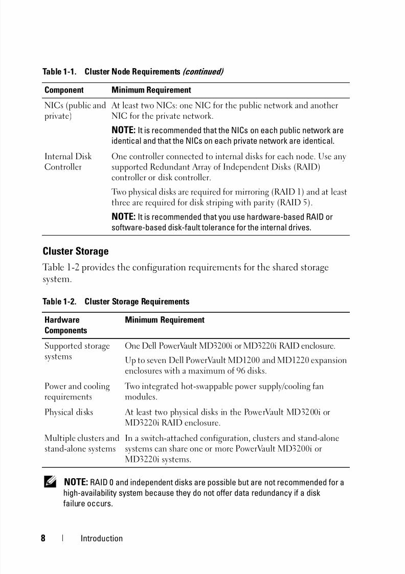
Cluster Storage
Table 1-2 provides the configuration requirements for the shared storagesystem.
NOTE: RAID 0 and independent disks are possible but are not recommended for a
high-availability system because they do not offer data redundancy if a disk
failure occurs.
NICs (public andprivate)
At least two NICs: one NIC for the public network and anotherNIC for the private network.
NOTE: It is recommended that the NICs on each public network are
identical and that the NICs on each private network are identical.
Internal DiskController
One controller connected to internal disks for each node. Use anysupported Redundant Array of Independent Disks (RAID)controller or disk controller.
Two physical disks are required for mirroring (RAID 1) and at least
three are required for disk striping with parity (RAID 5).
NOTE: It is recommended that you use hardware-based RAID or
software-based disk-fault tolerance for the internal drives.
Table 1-2. Cluster Storage Requirements
HardwareComponents
Minimum Requirement
Supported storagesystems
One Dell PowerVault MD3200i or MD3220i RAID enclosure.
Up to seven Dell PowerVault MD1200 and MD1220 expansionenclosures with a maximum of 96 disks.
Power and cooling
requirements
Two integrated hot-swappable power supply/cooling fan
modules.Physical disks At least two physical disks in the PowerVault MD3200i or
MD3220i RAID enclosure.
Multiple clusters andstand-alone systems
In a switch-attached configuration, clusters and stand-alonesystems can share one or more PowerVault MD3200i orMD3220i systems.
Table 1-1. Cluster Node Requirements (continued)
Component Minimum Requirement
5/14/2018 MD32x0i With Windiws Faliover Clusters Hardware Installation Guide - slidepdf.com
http://slidepdf.com/reader/full/md32x0i-with-windiws-faliover-clusters-hardware-installation-guide 9/78
Introduction 9
Cluster Storage Management Software
Dell PowerVault Modular Disk Storage ManagerThe software runs on the management station or any host attached to thearray to centrally manage the PowerVault MD3200i and MD3220i RAIDenclosures. You can use Dell PowerVault Modular Disk Storage Manager(MDSM) to perform tasks such as creating or managing RAID arrays, bindingvirtual disks, and downloading firmware.
MDSM is a graphical user interface (GUI) with wizard-guided tools and atask-based structure. MDSM is designed to:
• Reduce the complexity of installation, configuration, management, andperforming diagnostic tasks for the storage arrays.
• Contain an event monitoring service that is used to send alerts when acritical problem with the storage array occurs.
• Provide a command line interface (CLI) to run commands from anoperating system prompt.
Modular Disk Storage Manager Agent
This software resides on each cluster node to collect system-based topologydata that can be managed by the MDSM.
Multipath Software
Multipath I/O software (also referred to as the failover driver) is a softwareresiding on each cluster node that provides management of the redundantdata path between the system and the RAID enclosure. For the multipathsoftware to correctly manage a redundant path, the configuration must
provide for redundant NICs and cabling.The multipath software identifies the existence of multiple paths to a virtualdisk and establishes a preferred path to that disk. If any component in thepreferred path fails, the multipath software automatically re-routes I/Orequests to the alternate path so that the storage array continues to operatewithout interruption.

5/14/2018 MD32x0i With Windiws Faliover Clusters Hardware Installation Guide - slidepdf.com
http://slidepdf.com/reader/full/md32x0i-with-windiws-faliover-clusters-hardware-installation-guide 10/78
10 Introduction
Advanced Features
Advanced features for the PowerVault MD3200i and MD3220i RAID storage
systems include:• Snapshot Virtual Disk—Captures point-in-time images of a virtual disk
for backup, testing, or data processing without affecting the contents ofthe source virtual disk.
• Virtual Disk Copy—generates a full copy of data from the source virtualdisk to the target virtual disk in a storage array. You can use Virtual DiskCopy to back up data, copy data from disk groups that use smaller-capacityphysical disks to disk groups using greater capacity physical disks, or restore
snapshot virtual disk data to the source virtual disk.NOTE: For instructions on deploying the correct options in the cluster
environment, see "Using Advanced (Premium) PowerVault Modular Disk
Storage Manager Features" on page 61.

5/14/2018 MD32x0i With Windiws Faliover Clusters Hardware Installation Guide - slidepdf.com
http://slidepdf.com/reader/full/md32x0i-with-windiws-faliover-clusters-hardware-installation-guide 11/78
Introduction 11
Supported Cluster Configurations
Figure 1-1. Direct-Attached Cluster Configuration
NOTE: The configuration can have up to four nodes (N is either 2, 3, or 4). The
nodes can be:
• one cluster
• two different clusters• one cluster and stand-alone server(s)
Node NNode 1 ....................
corporate, public, or
private network
MD32xx i RAIDcontroller module 0
MD32xx i RAIDcontroller module 1
storage array

5/14/2018 MD32x0i With Windiws Faliover Clusters Hardware Installation Guide - slidepdf.com
http://slidepdf.com/reader/full/md32x0i-with-windiws-faliover-clusters-hardware-installation-guide 12/78
12 Introduction
Figure 1-2. Redundant Network-Attached Cluster Configuration
NOTE: The configuration can have up to 32 nodes. The nodes can be:
• one cluster (up to 16 nodes)
• multiple clusters
• multiple cluster(s) and stand-alone server(s)
corporate, public,or private network
storage array
Gigabit E thernet
swi tch 1
MD32xx i RAID
controller module 0
MD32xx i RAID
controller module 1
Gigabit Ethernet
switch 2
up to 32 hosts

5/14/2018 MD32x0i With Windiws Faliover Clusters Hardware Installation Guide - slidepdf.com
http://slidepdf.com/reader/full/md32x0i-with-windiws-faliover-clusters-hardware-installation-guide 13/78
Introduction 13
Other Documents You May Need
CAUTION: The safety information that shipped with your computer providesimportant safety and regulatory information. Warranty information may be
included within this document or as a separate document.
NOTE: To configure Dell blade system modules in a Dell PowerEdge Cluster,
see the Using Dell Blade Servers in a Dell PowerEdge High Availability Cluster
document at support.dell.com/manuals.
• The Rack Installation Guide included with your rack solution describeshow to install your system into a rack.
• The Getting Started Guide provides an overview to initially set upyour system.
• The Dell Failover Clusters with Microsoft Windows Server 2008 Installationand Troubleshooting Guide provides more information about deployingyour cluster.
• The Dell Cluster Configuration Support Matrices provides a list ofrecommended operating systems, hardware components, and driver orfirmware versions for your Dell Windows Server Failover Cluster.
• The operating system documentation describes how to install (ifnecessary), configure, and use the operating system software.
• The Dell PowerVault MD3200i and MD3220i RAID Enclosures Owner’sManual provides instructions for using the array management software toconfigure RAID systems.
• Documentation for any components you purchased separately providesinformation to configure and install those options.
• The Dell PowerVault tape library documentation provides information for
installing, troubleshooting, and upgrading the tape library.
• Updates are sometimes included with the system to describe changes tothe system, software, and/or documentation.
• The User's Guide for your PowerEdge system describes system featuresand technical specifications, the System Setup program (if applicable),software support, and the system configuration utility.
• The Dell PowerVault MD3200i and MD3220i Owner's Manual providesinformation about the hardware enclosure.
5/14/2018 MD32x0i With Windiws Faliover Clusters Hardware Installation Guide - slidepdf.com
http://slidepdf.com/reader/full/md32x0i-with-windiws-faliover-clusters-hardware-installation-guide 14/78
14 Introduction
• The PowerVault Modular Disk Storage Manager CLI Guide providesinformation about using the CLI.
• The Dell PowerVault MD3200i and MD3220i Resource DVD providesdocumentation for configuration and management tools, as well as the fulldocumentation set included here.
• The Dell PowerVault MD Getting Started Guide provides an overview ofsetting up and cabling your storage array.
• The Dell PowerVault MD3200i and MD3220i Storage Arrays DeploymentGuide provides installation and configuration instructions to configure thestorage system for initial use.
• The Dell PowerVault MD Systems Support Matrix provides information onsupported software and hardware for PowerVault MD systems.
NOTE: Always read the updates first because they often supersede
information in other documents.
• Release notes or readme files may be included to provide last-minuteupdates to the system documentation or advance technical referencematerial intended for experienced users or technicians.

5/14/2018 MD32x0i With Windiws Faliover Clusters Hardware Installation Guide - slidepdf.com
http://slidepdf.com/reader/full/md32x0i-with-windiws-faliover-clusters-hardware-installation-guide 15/78
Cabling Your Cluster Hardware 15
2Cabling Your Cluster HardwareThe following sections provide information on how to cable variouscomponents of your cluster.
Cabling the Mouse, Keyboard, and MonitorWhen installing a cluster configuration in a rack, you must include a switchbox to connect the mouse, keyboard, and monitor to the nodes. See thedocumentation included with your rack for instructions on cabling eachnode's connections to the switch box.
Cabling the Power SuppliesTo ensure that the specific power requirements are satisfied, see thedocumentation for each component in your cluster solution.
It is recommended that you adhere to the following guidelines to protect your
cluster solution from power-related failures:• For nodes with multiple power supplies, plug each power supply into a
separate AC circuit.
• Use uninterruptible power supplies (UPS).
• For some environments, consider having backup generators and powerfrom separate electrical substations.
Figure 2-1 and Figure 2-2 illustrate recommended methods for power cabling
of a cluster solution consisting of two Dell PowerEdge systems and onestorage system. To ensure redundancy, the primary power supplies of all thecomponents are grouped onto one or two circuits and the redundant powersupplies are grouped onto a different circuit.

5/14/2018 MD32x0i With Windiws Faliover Clusters Hardware Installation Guide - slidepdf.com
http://slidepdf.com/reader/full/md32x0i-with-windiws-faliover-clusters-hardware-installation-guide 16/78
16 Cabling Your Cluster Hardware
Figure 2-1. Power Cabling Examples With One Power Supply in the PowerEdgeSystems
NOTE: This illustration is intended only to demonstrate the power distribution of the
components.
primary power supplies on one
AC power strip (or one AC PDU
[not shown])
redundant power supplies on one
AC power strip (or one AC PDU
[not shown])
MD32xx i
RAID
controller
module 1
MD32xx i
RAID
controller
module 0
MD32xx i
RAID
controller
module 1

5/14/2018 MD32x0i With Windiws Faliover Clusters Hardware Installation Guide - slidepdf.com
http://slidepdf.com/reader/full/md32x0i-with-windiws-faliover-clusters-hardware-installation-guide 17/78
Cabling Your Cluster Hardware 17
Figure 2-2. Power Cabling Example With Two Power Supplies in the PowerEdgeSystems
NOTE: This illustration is intended only to demonstrate the power distribution of the
components.
primary power supplies on one
AC power strip (or one AC PDU
[not shown])
redundant power supplies on one
AC power strip (or one AC PDU
[not shown])
MD32xx i
RAID
controller
module 0
MD32xx i
RAID
controller
module 1
5/14/2018 MD32x0i With Windiws Faliover Clusters Hardware Installation Guide - slidepdf.com
http://slidepdf.com/reader/full/md32x0i-with-windiws-faliover-clusters-hardware-installation-guide 18/78
18 Cabling Your Cluster Hardware
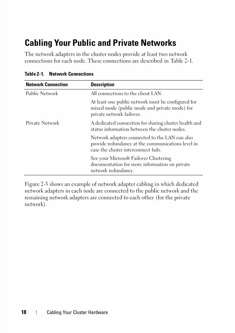
Cabling Your Public and Private NetworksThe network adapters in the cluster nodes provide at least two networkconnections for each node. These connections are described in Table 2-1.
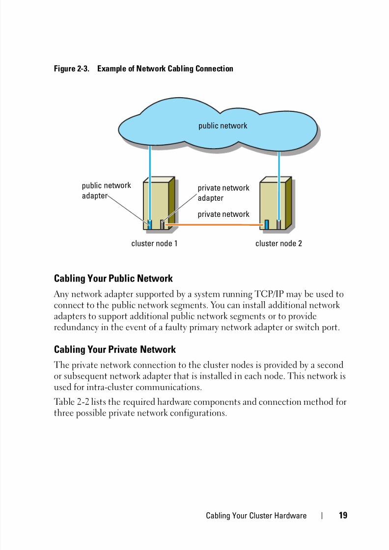
Figure 2-3 shows an example of network adapter cabling in which dedicatednetwork adapters in each node are connected to the public network and theremaining network adapters are connected to each other (for the privatenetwork).
Table 2-1. Network Connections
Network Connection Description
Public Network All connections to the client LAN.
At least one public network must be configured formixed mode (public mode and private mode) for
private network failover.Private Network A dedicated connection for sharing cluster health and
status information between the cluster nodes.
Network adapters connected to the LAN can alsoprovide redundancy at the communications level incase the cluster interconnect fails.
See your Microsoft Failover Clusteringdocumentation for more information on privatenetwork redundancy.
5/14/2018 MD32x0i With Windiws Faliover Clusters Hardware Installation Guide - slidepdf.com
http://slidepdf.com/reader/full/md32x0i-with-windiws-faliover-clusters-hardware-installation-guide 19/78
Cabling Your Cluster Hardware 19
Figure 2-3. Example of Network Cabling Connection
Cabling Your Public Network
Any network adapter supported by a system running TCP/IP may be used toconnect to the public network segments. You can install additional networkadapters to support additional public network segments or to provideredundancy in the event of a faulty primary network adapter or switch port.
Cabling Your Private Network
The private network connection to the cluster nodes is provided by a secondor subsequent network adapter that is installed in each node. This network is
used for intra-cluster communications.
Table 2-2 lists the required hardware components and connection method forthree possible private network configurations.
public network
public ne twork
adap ter private networkadapter
cluster node 1 cluster node 2
private network

5/14/2018 MD32x0i With Windiws Faliover Clusters Hardware Installation Guide - slidepdf.com
http://slidepdf.com/reader/full/md32x0i-with-windiws-faliover-clusters-hardware-installation-guide 20/78
20 Cabling Your Cluster Hardware
NOTE: Throughout this document, Ethernet refers to either Gigabit Ethernet or
10 Gigabit Ethernet.
Using Dual-Port Network Adapters for Your Private Network
You can configure your cluster to use the public network as a failover for
private network communications. However, if dual-port network adapters areused, do not use two ports simultaneously to support both the public andprivate networks.
NIC Teaming
Network Interface Card (NIC) teaming combines two or more NICs toprovide load balancing and/or fault tolerance. Your cluster supports NICteaming, but only in a public network; NIC teaming is not supported in a
private network.
Table 2-2. Private Network Hardware Components and Connections
Method Hardware Components ConnectionNetwork switch Gigabit or 10 Gigabit
Ethernet networkadapters and switches.
Depending on the hardware,connect the CAT5e or CAT6cables, the multimode opticalcables with Local Connectors(LCs), or the twinax cablesfrom the network adapters inthe nodes to a switch.
Point-to-Point (two node
cluster only)
Copper Gigabit or 10
Gigabit Ethernet networkadapters with RJ-45connectors.
Connect a standard CAT5e or
CAT6 Ethernet cable betweenthe network adapters in bothnodes.
Copper 10 GigabitEthernet networkadapters with SFP+connectors
Connect a twinax cablebetween the network adaptersin both nodes.
Optical Gigabit or 10
Gigabit Ethernet networkadapters with LCconnectors
Connect a multi-mode optical
cable between the networkadapters in both nodes.
5/14/2018 MD32x0i With Windiws Faliover Clusters Hardware Installation Guide - slidepdf.com
http://slidepdf.com/reader/full/md32x0i-with-windiws-faliover-clusters-hardware-installation-guide 21/78
Cabling Your Cluster Hardware 21
You must use the same brand of NICs in a team, and you cannot mix brandsof teaming drivers.
Cabling the Storage SystemsThis section provides information for connecting your cluster to a storagesystem.
NOTE: To configure Dell blade system modules in a Dell PowerEdge Cluster, see
Using Dell Blade Servers in a Dell PowerEdge High Availability Cluster at
support.dell.com/manuals.
NOTE:For more details on storage hardware settings and descriptions, see
Dell PowerVault MD3200i and MD3220i RAID Enclosure Owner's Manual at
support.dell.com/manuals.
Storage management can be either in-band through the host-to-controllerinterface or out-of-band using an Ethernet connection. For out-of-bandstorage management, cable the Ethernet ports on the storage array to thepublic network.
NOTE: It is recommended that you configure your Dell PowerVault MD3200i and
MD3220i to use out-of-band management.
Cabling the Cluster in Direct-Attached Configuration
In the direct-attached configuration, each cluster node is directly attached tothe PowerVault MD3200i or MD3220i RAID controller modules using twonetwork cables, and either one dual-port NIC or two single-port NICs.
If a component fails in the storage path such as the port, the cable, or thestorage controller, the multipath software automatically re-routes the I/Orequests to the alternate path so that the storage array continues to operatewithout interruption. The configuration with two single-port NICs provideshigher availability; a NIC failure does not cause failover cluster to movecluster resources to the other cluster node.
To cable the cluster:
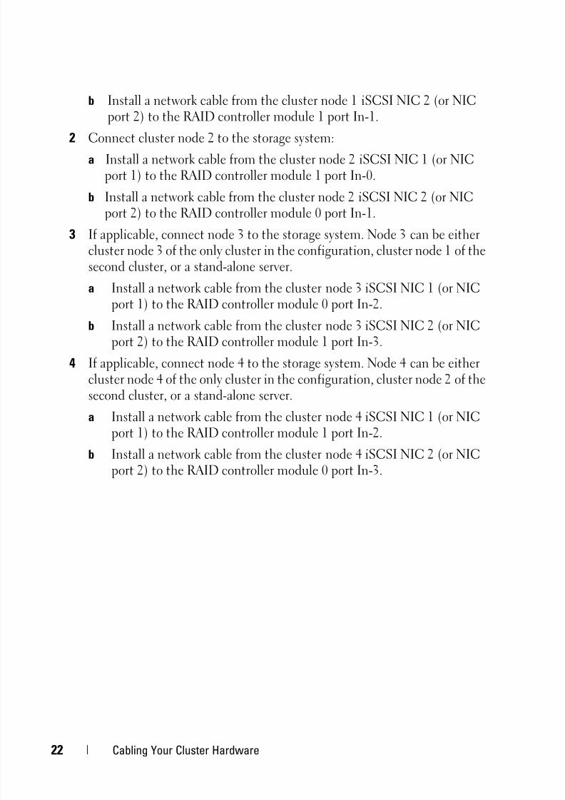
1 Connect cluster node 1 to the storage system:
a Install a network cable from the cluster node 1 iSCSI NIC 1 (or NICport 1) to the RAID controller module 0 port In-0.
5/14/2018 MD32x0i With Windiws Faliover Clusters Hardware Installation Guide - slidepdf.com
http://slidepdf.com/reader/full/md32x0i-with-windiws-faliover-clusters-hardware-installation-guide 22/78
22 Cabling Your Cluster Hardware
b Install a network cable from the cluster node 1 iSCSI NIC 2 (or NICport 2) to the RAID controller module 1 port In-1.
2 Connect cluster node 2 to the storage system:a Install a network cable from the cluster node 2 iSCSI NIC 1 (or NIC
port 1) to the RAID controller module 1 port In-0.
b Install a network cable from the cluster node 2 iSCSI NIC 2 (or NICport 2) to the RAID controller module 0 port In-1.
3 If applicable, connect node 3 to the storage system. Node 3 can be eithercluster node 3 of the only cluster in the configuration, cluster node 1 of thesecond cluster, or a stand-alone server.
a Install a network cable from the cluster node 3 iSCSI NIC 1 (or NICport 1) to the RAID controller module 0 port In-2.
b Install a network cable from the cluster node 3 iSCSI NIC 2 (or NICport 2) to the RAID controller module 1 port In-3.
4 If applicable, connect node 4 to the storage system. Node 4 can be eithercluster node 4 of the only cluster in the configuration, cluster node 2 of thesecond cluster, or a stand-alone server.
a Install a network cable from the cluster node 4 iSCSI NIC 1 (or NICport 1) to the RAID controller module 1 port In-2.
b Install a network cable from the cluster node 4 iSCSI NIC 2 (or NICport 2) to the RAID controller module 0 port In-3.
5/14/2018 MD32x0i With Windiws Faliover Clusters Hardware Installation Guide - slidepdf.com
http://slidepdf.com/reader/full/md32x0i-with-windiws-faliover-clusters-hardware-installation-guide 23/78
Cabling Your Cluster Hardware 23
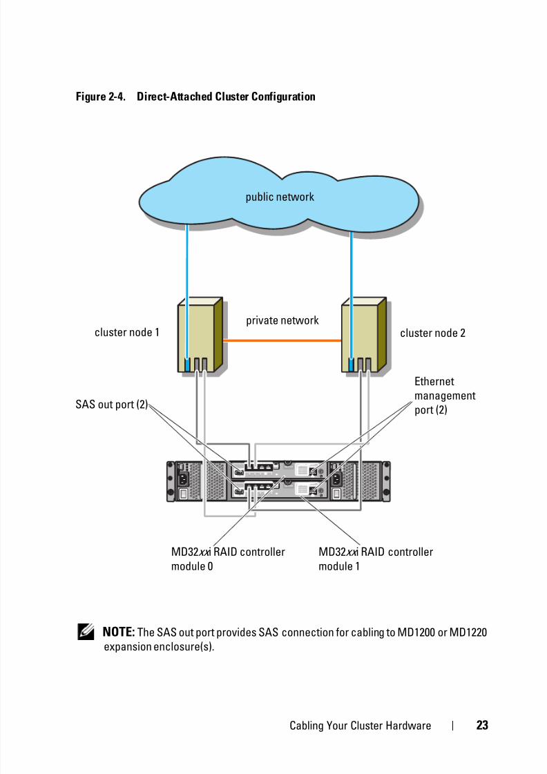
Figure 2-4. Direct-Attached Cluster Configuration
NOTE: The SAS out port provides SAS connection for cabling to MD1200 or MD1220
expansion enclosure(s).
MD32xx i RAID controller
module 0
cluster node 2cluster node 1private network
public network
Ethernet
management
port (2)SAS out port (2)
MD32xx i RAID controller
module 1

5/14/2018 MD32x0i With Windiws Faliover Clusters Hardware Installation Guide - slidepdf.com
http://slidepdf.com/reader/full/md32x0i-with-windiws-faliover-clusters-hardware-installation-guide 24/78
24 Cabling Your Cluster Hardware
Cabling the Cluster in Network-Attached Configuration
In the network-attached configuration, each cluster node attaches to the
storage system using redundant IP storage area network (SAN) industry-standard 1 Gb Ethernet switches, and either with one dual-port iSCSI NIC ortwo single-port iSCSI NICs. If a component fails in the storage path such asthe iSCSI NIC, the cable, the switch, or the storage controller, the multipathsoftware automatically re-routes the I/O requests to the alternate path so thatthe storage array continues to operate without interruption. Theconfiguration with two single-port NICs provides higher availability; a NICfailure does not cause Microsoft Failover Cluster to move cluster resources tothe other cluster node.
This configuration can support up to 32 hosts simultaneously. Examples ofthis configuration are:
• One cluster.
• Two clusters.
• One eight-node cluster, two two-node clusters, and one stand-alonesystem.
To cable the cluster:
1 Connect the storage system to the iSCSI network:
a Install a network cable from switch 1 to controller 0 port In-0.
b Install a network cable from switch 1 to controller 1 port In-0.
c Install a network cable from switch 2 to controller 0 port In-1.
d Install a network cable from switch 2 to controller 1 port In-1.
e Install a network cable from switch 1 to controller 0 port In-2.
f Install a network cable from switch 1 to controller 1 port In-2.g Install a network cable from switch 2 to controller 0 port In-3.
h Install a network cable from switch 2 to controller 1 port In-3.
2 Connect the cluster to the iSCSI network:
a Install a network cable from the cluster node 1 iSCSI NIC 1 (or NICport 1) to the network switch 1.
b Install a network cable from the cluster node 1 iSCSI NIC 2 (or NIC
port 2) to the network switch 2.

5/14/2018 MD32x0i With Windiws Faliover Clusters Hardware Installation Guide - slidepdf.com
http://slidepdf.com/reader/full/md32x0i-with-windiws-faliover-clusters-hardware-installation-guide 25/78
Cabling Your Cluster Hardware 25
c Repeat step a and step b for each additional cluster node.
3 Repeat step 2 to connect additional clusters or stand-alone systems to the
iSCSI network.

5/14/2018 MD32x0i With Windiws Faliover Clusters Hardware Installation Guide - slidepdf.com
http://slidepdf.com/reader/full/md32x0i-with-windiws-faliover-clusters-hardware-installation-guide 26/78
26 Cabling Your Cluster Hardware
Figure 2-5. Network-Attached Cluster Configuration
2 to n cluster
nodes
MD32xx i RAID
controller module 0
SAS out
port (2)
IP SAN
(dual
GigabitEthernet
switch) (2)
private network
public network
MD32xx i RAID
controller module 1
Ethernet
management
port (2)

5/14/2018 MD32x0i With Windiws Faliover Clusters Hardware Installation Guide - slidepdf.com
http://slidepdf.com/reader/full/md32x0i-with-windiws-faliover-clusters-hardware-installation-guide 27/78
Cabling Your Cluster Hardware 27
Connecting a PowerEdge Cluster to Multiple PowerVault MD3200i orMD3220i Storage Systems
You can increase your cluster storage capacity by attaching multiple storagesystems to your cluster using redundant network switches. The PowerEdgecluster systems support configurations with multiple PowerVault MD3200i orMD3220i storage systems attached to clustered systems. In this scenario, theFailover Cluster software can fail over disk drives in any cluster-attachedshared storage system between the cluster nodes.

5/14/2018 MD32x0i With Windiws Faliover Clusters Hardware Installation Guide - slidepdf.com
http://slidepdf.com/reader/full/md32x0i-with-windiws-faliover-clusters-hardware-installation-guide 28/78
28 Cabling Your Cluster Hardware
Figure 2-6. Network-Attached Cluster Configuration With Multiple Storage Arrays
public network
private network
2 to n cluster
nodes
IP SAN (dual
Gigabit Ethernet
switch (2)
MD32xx i RAID
controller module 0
MD32xx i RAID
controller module 1
storage array 1
storage array 2

5/14/2018 MD32x0i With Windiws Faliover Clusters Hardware Installation Guide - slidepdf.com
http://slidepdf.com/reader/full/md32x0i-with-windiws-faliover-clusters-hardware-installation-guide 29/78
Cabling Your Cluster Hardware 29
When attaching multiple PowerVault MD3200i and MD3220i storagesystems with your cluster, the following rules apply:
• A maximum of four Power Vault MD3200i and MD3220i storage systemsper cluster.
• The shared storage systems and firmware must be identical. Usingdissimilar storage systems and firmware for your shared storage is notsupported.
• Windows limits access to drives using limited drive letters which is 22.Because drive letters A through D are reserved for local disks, a maximumof 22 drive letters (E to Z) can be used for your storage system disks.
• Windows Server 2008 Enterprise Edition supports mount points, allowinggreater than 22 drives per cluster.

5/14/2018 MD32x0i With Windiws Faliover Clusters Hardware Installation Guide - slidepdf.com
http://slidepdf.com/reader/full/md32x0i-with-windiws-faliover-clusters-hardware-installation-guide 30/78
30 Cabling Your Cluster Hardware

5/14/2018 MD32x0i With Windiws Faliover Clusters Hardware Installation Guide - slidepdf.com
http://slidepdf.com/reader/full/md32x0i-with-windiws-faliover-clusters-hardware-installation-guide 31/78
Preparing Your Systems for Clustering 31
3Preparing Your Systems forClustering
CAUTION: Only trained service technicians are authorized to remove and accessany of the components inside the system. See the safety information that shippedwith your computer for complete information about safety precautions, working
inside the computer, and protecting against electrostatic discharge.
Cluster Configuration Overview1 Ensure that your site can handle the cluster’s power requirements.
Contact your sales representative for information about your region'spower requirements.
2 Install the servers, the shared storage array(s), and the interconnectswitches (example: in an equipment rack), and ensure that all these
components are turned on. NOTE: For more information on step 3 through step 7 and step 10 through
step 12, see the "Preparing your systems for clustering" section of the
Dell Failover Clusters with Microsoft Windows Server 2008 Installation and
Troubleshooting Guide at support.dell.com/manuals.
3 Deploy the operating system (including any relevant service pack andhotfixes), network adapter drivers, and storage adapter drivers (includingMultipath I/O drivers (MPIO)) on each of the servers that must becomecluster nodes. Depending on the deployment method that is used, it maybe necessary to provide a network connection to successfully completethis step.
NOTE: You can record the Cluster configuration to the Cluster Data Form to
help in planning and deployment of your cluster. For more information, see the
"Cluster Data Form" on page 71 and the iSCSI configuration information in the
worksheet located at "iSCSI Configuration Worksheet" on page 73.
4 Establish the physical network topology and the TCP/IP settings fornetwork adapters on each server node to provide access to the cluster
public and private networks.

5/14/2018 MD32x0i With Windiws Faliover Clusters Hardware Installation Guide - slidepdf.com
http://slidepdf.com/reader/full/md32x0i-with-windiws-faliover-clusters-hardware-installation-guide 32/78
32 Preparing Your Systems for Clustering
5 Configure each server node as a member server in the same Windows Active Directory Domain.
NOTE: You can configure the cluster nodes as Domain Controllers. For moreinformation, see the "Selecting a Domain Model" section of the Dell Failover
Clusters with Microsoft Windows Server 2008 Installation and
Troubleshooting Guide at support.dell.com/manuals.
6 Establish the physical storage topology and any required storage networksettings to provide connectivity between the storage array and the serversthat must be configured as cluster nodes. Configure the storage system(s)as described in your storage system documentation.
7 Use storage array management tools to create at least one logical unitnumber (LUN). The LUN is used as a witness disk for Microsoft WindowsServer 2008 Failover cluster. Ensure that this LUN is presented to theservers that must be configured as cluster nodes.
NOTE: It is recommended that you configure the LUN on a single node, for
security reasons, as mentioned in step 8 when you are setting up the cluster.
Later, you can configure the LUN as mentioned in step 9 so that other cluster
nodes can access it.
8Select one of the systems and form a new failover cluster by configuringthe cluster name, cluster management IP, and quorum resource. For moreinformation, see "Preparing Your Systems for Clustering" on page 31.
NOTE: For Windows Server 2008 Failover Clusters, run the Cluster Validation
Wizard to ensure that your system is ready to form the cluster.
9 Join the remaining node(s) to the failover cluster. For more information,see "Preparing Your Systems for Clustering" on page 31.
10 Configure roles for cluster networks. Take any network interfaces that are
used for iSCSI storage (or for other purposes outside of the cluster) out ofthe control of the cluster.

5/14/2018 MD32x0i With Windiws Faliover Clusters Hardware Installation Guide - slidepdf.com
http://slidepdf.com/reader/full/md32x0i-with-windiws-faliover-clusters-hardware-installation-guide 33/78
Preparing Your Systems for Clustering 33
11 Test the failover capabilities of your new cluster.
NOTE: You can also use the Cluster Validation Wizard.
12 Configure highly-available applications and services on your failovercluster. Depending on your configuration, this may also require providingadditional LUNs to the cluster or creating new cluster resource groups.Test the failover capabilities of the new resources.
13 Configure client systems to access the highly available applications andservices that are hosted on your failover cluster.
Installation OverviewEach node in your Dell Windows Server failover cluster must have the samerelease, edition, service pack, and processor architecture of the WindowsServer operating system installed. For example, all nodes in your cluster maybe configured with Windows Server 2008 R2, Enterprise x64 Edition. If theoperating system varies among nodes, it is not possible to configure a failovercluster successfully. It is recommended to establish system roles prior toconfiguring a failover cluster, depending on the operating system configuredon your cluster.
For a list of recommended operating systems, hardware components, anddriver or firmware versions for your Dell Windows Server Failover Cluster,see the Dell Cluster Configuration Support Matrices at dell.com/ha.
For more information on deploying your cluster with the Windows Server2008 operating systems, see the Dell Failover Clusters with Microsoft WindowsServer 2008 Installation and Troubleshooting Guide atsupport.dell.com/manuals.

5/14/2018 MD32x0i With Windiws Faliover Clusters Hardware Installation Guide - slidepdf.com
http://slidepdf.com/reader/full/md32x0i-with-windiws-faliover-clusters-hardware-installation-guide 34/78
34 Preparing Your Systems for Clustering
The following sub-sections describe steps that enable you to establishcommunication between the cluster nodes and your shared MD3200i or
MD3220i storage array(s), and to present disks from the storage array to thecluster:
1 Installing the iSCSI NICs.
2 Installing the Microsoft iSCSI Software Initiator.
3 Installing and Configuring the Storage Management Software.
4 Configuring the Shared Storage System.
5 Configuring a Failover Cluster.
Installing the iSCSI NICs
It is recommended that you install the latest supported version of the driver.If the NIC driver requires any service packs or hotfixes to be installed alongwith the operating system, install them at this time.
For a list of recommended operating systems, hardware components, anddriver or firmware versions for your Dell Windows Server Failover Cluster, seethe Dell Cluster Configuration Support Matrices at dell.com/ha.
Enabling TOE NIC
The purpose of TOE is to take the TCP/IP packets to be processed by thesystem processor(s) and offload them on the NIC. The TOE eliminates thebottlenecks with applications that generate significant network traffic, freeingup CPU cycles, and the amount of available main memory bandwidth. TOENICs provide increased performance for iSCSI traffic.
NOTE: All the nodes in a cluster solution must use similar NICs (TOE NICs or
regular NICs) for iSCSI traffic. Combining TOE NICs and regular NICs is not
supported in a cluster solution.
You must configure the public, private, and iSCSI networks in each nodebefore you install Microsoft Failover Clustering. The following sectionsexplain the principles and procedures related to the networking prerequisites.
NOTE: If the iSCSI networks are not configured to use DHCP, you must configure
static IPs. To fully utilize the iSCSI ports on the storage system, the IPs are
configured such that access to each iSCSI port is balanced among the cluster
nodes. For example, if the four subnets on the storage systems are .10, .11, .12, and
.13, the two iSCSI NICs on the first cluster nodes can be on .10 and .11 subnets, the

5/14/2018 MD32x0i With Windiws Faliover Clusters Hardware Installation Guide - slidepdf.com
http://slidepdf.com/reader/full/md32x0i-with-windiws-faliover-clusters-hardware-installation-guide 35/78
Preparing Your Systems for Clustering 35
two NICs on the second cluster node can be on .12 and .13 subnets, the two iSCSI
NICs on the third cluster node can be on .10 and .11 subnets, and the fourth cluster
node can be on .12 and .13 subnets.
Installing the Microsoft iSCSI Software Initiator
Microsoft iSCSI Initiator is installed natively on Windows Server 2008.
Installing and Configuring the Storage Management Software
The PowerVault MD3200i and MD3220i storage software installer providesfeatures that include the core software, providers, and optional utilities.
The core software feature includes the host-based storage agent, multipathdriver, and MDSM application used to configure, manage and monitor thestorage array solution.
The providers feature includes a provider for the Microsoft Virtual DiskService (VDS) and Microsoft Volume Shadow-Copy Service (VSS)frameworks as well as a provider for the SNIA Storage Management InitiativeSpecification (SMI-S) standard.
The Modular Disk Configuration Utility (MDCU) is an optional utility that
provides a consolidated approach for configuring the management ports,iSCSI host ports, and creating sessions for the iSCSI Modular Disk storagearrays. It is recommended that you use MDCU to configure iSCSI on eachhost connected to the PowerVault MD3200i or MD3220i.
NOTE: For more information about the Microsoft VDS, Microsoft VSS providers,
see the Owner's Manual. For more information about working with the SMI-S
provider, see the SMI-S Programmer's Guide .
Installing the Storage Management Software
1 Close all other programs before installing any new software.
2 Insert the resource media.
3 Select Install MD32 xxi Storage Software.
4 Install the MD Storage software.
5 Select one of the following installation options:
5/14/2018 MD32x0i With Windiws Faliover Clusters Hardware Installation Guide - slidepdf.com
http://slidepdf.com/reader/full/md32x0i-with-windiws-faliover-clusters-hardware-installation-guide 36/78
36 Preparing Your Systems for Clustering
– Full (recommended)—This package installs core software, providers,and utilities. It includes the necessary host-based storage agent,
multipath driver, MD Storage Manager, providers, and optionalutilities.
– Host Only—This package includes the host-based storage agent,multipath drivers, and optional utilities required to configure the host.
– Management Station—This package includes the MD StorageManager, providers, and optional utilities.
– Custom—This option allows you to select specific components.
6 Reboot each host server.
You can manage a storage array in two ways:
• Out-of-band management
• In-band management
NOTE: It is recommended that you use out-of-band management.
5/14/2018 MD32x0i With Windiws Faliover Clusters Hardware Installation Guide - slidepdf.com
http://slidepdf.com/reader/full/md32x0i-with-windiws-faliover-clusters-hardware-installation-guide 37/78
Preparing Your Systems for Clustering 37
Configuring the Shared Storage System
Before you begin configuring iSCSI, you must fill out the "iSCSI
Configuration Worksheet" on page 73. Gathering this type of informationabout your network prior to starting the configuration steps helps youcomplete the process faster.
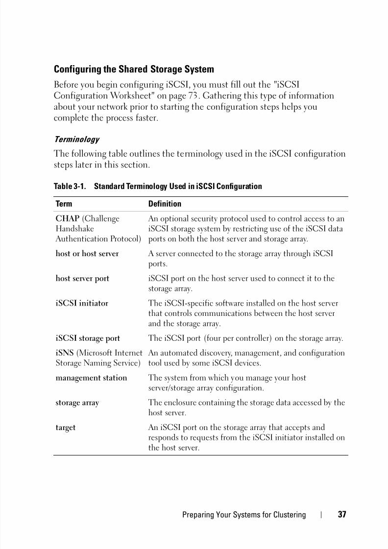
Terminology
The following table outlines the terminology used in the iSCSI configurationsteps later in this section.
Table 3-1. Standard Terminology Used in iSCSI Configuration
Term Definition
CHAP (ChallengeHandshake Authentication Protocol)
An optional security protocol used to control access to aniSCSI storage system by restricting use of the iSCSI dataports on both the host server and storage array.
host or host server A server connected to the storage array through iSCSIports.
host server port iSCSI port on the host server used to connect it to the
storage array.
iSCSI initiator The iSCSI-specific software installed on the host serverthat controls communications between the host serverand the storage array.
iSCSI storage port The iSCSI port (four per controller) on the storage array.
iSNS (Microsoft InternetStorage Naming Service)
An automated discovery, management, and configurationtool used by some iSCSI devices.
management station The system from which you manage your hostserver/storage array configuration.
storage array The enclosure containing the storage data accessed by thehost server.
target An iSCSI port on the storage array that accepts andresponds to requests from the iSCSI initiator installed onthe host server.

5/14/2018 MD32x0i With Windiws Faliover Clusters Hardware Installation Guide - slidepdf.com
http://slidepdf.com/reader/full/md32x0i-with-windiws-faliover-clusters-hardware-installation-guide 38/78
38 Preparing Your Systems for Clustering
Using Internet Storage Naming Service Server
Internet Storage Naming Service Server (iSNS) eliminates the need to
manually configure each individual storage array with a specific list ofinitiators and target IP addresses. Instead, iSNS automatically discovers,manages, and configures all iSCSI devices in your environment.
For more information on iSNS, including installation and configuration, go tomicrosoft.com.
Configuring iSCSI on Your Storage Array
The following sections contain step-by-step instructions for configuring
iSCSI on your storage array. However, before beginning, it is important tounderstand where each of these steps occur in relation to your hostserver/storage array environment.
Table 3-2 contains the sequence of steps for configuring each specific iSCSIconnections and where it occurs. The following sub-sections describe each ofthe steps in more detail.
Table 3-2. Host Server vs. Storage Array
This step is performed on the HOSTSERVER using the Microsoft iSCSIInitiator:
This step is performed on the STORAGEARRAY using MD Storage Manager:
1 Discover the storage array
2 Configure the iSCSI ports on the storagearray authentication on the storage array
3 Perform target discovery from theiSCSI initiator
4 Configure host access5 (Optional) Configure CHAP
6 (Optional) Configure CHAPauthentication on the host server
7 Connect to the storage array fromthe host server
8 (Optional) Set up in-band management
5/14/2018 MD32x0i With Windiws Faliover Clusters Hardware Installation Guide - slidepdf.com
http://slidepdf.com/reader/full/md32x0i-with-windiws-faliover-clusters-hardware-installation-guide 39/78
Preparing Your Systems for Clustering 39
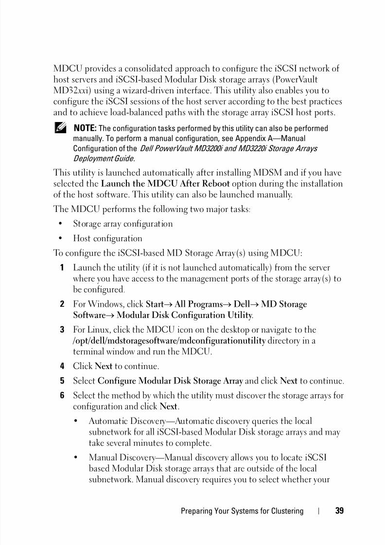
MDCU provides a consolidated approach to configure the iSCSI network ofhost servers and iSCSI-based Modular Disk storage arrays (PowerVault
MD32 xxi) using a wizard-driven interface. This utility also enables you toconfigure the iSCSI sessions of the host server according to the best practicesand to achieve load-balanced paths with the storage array iSCSI host ports.
NOTE: The configuration tasks performed by this utility can also be performed
manually. To perform a manual configuration, see Appendix A—Manual
Configuration of the Dell PowerVault MD3200i and MD3220i Storage Arrays
Deployment Guide .
This utility is launched automatically after installing MDSM and if you haveselected the Launch the MDCU After Reboot option during the installationof the host software. This utility can also be launched manually.
The MDCU performs the following two major tasks:
• Storage array configuration
• Host configuration
To configure the iSCSI-based MD Storage Array(s) using MDCU:
1 Launch the utility (if it is not launched automatically) from the serverwhere you have access to the management ports of the storage array(s) tobe configured.
2 For Windows, click StartAll Programs Dell MD StorageSoftwareModular Disk Configuration Utility.
3 For Linux, click the MDCU icon on the desktop or navigate to the /opt/dell/mdstoragesoftware/mdconfigurationutility directory in aterminal window and run the MDCU.
4 Click Next to continue.
5 Select Configure Modular Disk Storage Array and click Next to continue.6 Select the method by which the utility must discover the storage arrays for
configuration and click Next.
• Automatic Discovery—Automatic discovery queries the localsubnetwork for all iSCSI-based Modular Disk storage arrays and maytake several minutes to complete.
• Manual Discovery—Manual discovery allows you to locate iSCSIbased Modular Disk storage arrays that are outside of the localsubnetwork. Manual discovery requires you to select whether your

5/14/2018 MD32x0i With Windiws Faliover Clusters Hardware Installation Guide - slidepdf.com
http://slidepdf.com/reader/full/md32x0i-with-windiws-faliover-clusters-hardware-installation-guide 40/78
40 Preparing Your Systems for Clustering
storage array has a single controller (simplex) or dual controllers(duplex) and whether to use IPv4 or IPv6 protocol to communicate
with the management port of the storage array.The next screen displays a list of the iSCSI-based MD storage arrays that werediscovered based on the discovery process selected in step 3. If you selectAutomatic Discovery, the screen displays a list of iSCSI-based MD storagearrays that were discovered in the subnet. If you select Manual Discovery, thelist contains only the array whose IP address was entered. To add additionalarrays to the list, click on the Add button on this screen.
7 Select the array by clicking the radio button of the corresponding storage
array and then click Next.8 Enter the name of the storage array and the password.
9 Click the Set Password check-box if you want to set a new password for thearray and enter the new password in the New Password and Confirm NewPassword fields. Click Next to continue.
10 Select the IP protocol (IPv4/IPv6) that the management ports must use. Also for each protocol, select whether the configuration of themanagement port IP addresses requires to be done manually or
automatically. See the online help for more details.11 Click Next to continue. If you have not selected the Specify
Configuration Manually option for any of the two protocols, go to step 13.
12 If you have selected Specify Configuration Manually for any of the twoprotocols in the last step, a series of screens showing the backend viewimage of the storage array controllers are displayed. Each image containsIP addresses of management ports of the controllers. Also, each image hasa management port highlighted in red.
• For IPv4 address of the highlighted port, enter the IP address, subnetmask and gateway address in the fields below the image to modify it.
• For IPv6 address of the highlighted port, enter the local IP address,routable IP, and router IP address in the fields below the image tomodify it.
Click Next to continue through these images to complete theconfiguration of all the management ports for the selected protocols.

5/14/2018 MD32x0i With Windiws Faliover Clusters Hardware Installation Guide - slidepdf.com
http://slidepdf.com/reader/full/md32x0i-with-windiws-faliover-clusters-hardware-installation-guide 41/78
Preparing Your Systems for Clustering 41
13 In the CHAP Configuration screen, select the CHAP method and clickNext. For more information on CHAP see "Understanding CHAP
Authentication" on page 42.14 In the Summary screen, review the information that you entered for the
storage array.
15 Click Apply to save the changes to the storage array.
NOTE: Click Cancel Array to cancel the configuration for the storage array and go
back to select another storage array for configuration.
16 On the Configure Additional Arrays screen, select whether you want toconfigure an additional array. Click Next to continue.
17 If you selected Yes in step 16, then repeat step 6 through step 15 toconfigure an additional array.
If you selected No in step 16, perform the following on the ConfigureHost Connectivity screen:
a Select whether you want to configure the connectivity for the currenthost’s iSCSI initiator.
b Click Next to continue.
c Click No to complete the configuration task and go to step f.
d Click Yes to configure the connectivity for the current host’s iSCSIinitiator. The Select Storage Array screen is displayed.
e Select the storage array that you want to configure for connectivity tothe local host.
f Click Finish on the last screen to exit the utility.
NOTE: The storage arrays just configured by the utility are marked as Configuration
Complete against their names in the list. This helps you to identify the arrays thatare ready to be configured for host access.
18 In the Storage Array Login screen, perform the following:
a In the Controller# column, select the iSCSI host port of the storagearray that you want to configure and its IP address(es).
b In the Host Address column, from the drop-down menu, select thehost IP address that must login to the iSCSI host port of the storagearray.

5/14/2018 MD32x0i With Windiws Faliover Clusters Hardware Installation Guide - slidepdf.com
http://slidepdf.com/reader/full/md32x0i-with-windiws-faliover-clusters-hardware-installation-guide 42/78
42 Preparing Your Systems for Clustering
c Click Next if you want to enter the login information for anothercontroller or click Apply to commit the log in information.
19 In the Connect to Additional Arrays screen, select if you want to connectto another storage array. To connect to another storage array, repeat thesteps above starting from step d. If you do not want to connect toadditional arrays, click Finish on the final screen to exit the utility.
Understanding CHAP Authentication
Before proceeding to either "Configuring CHAP Authentication on theStorage Array (Optional)" on page 43 or "Configuring CHAP Authentication
on the Host Server (Optional)" on page 45,
it would be useful to gain anoverview of how CHAP authentication works.
What is CHAP?
Challenge Handshake Authentication Protocol (CHAP) is an optional iSCSIauthentication method where the storage array (target) authenticates iSCSIinitiators on the host server. Two types of CHAP are supported: target CHAPand mutual CHAP.
Target CHAP
In target CHAP, the storage array authenticates all requests for access issuedby the iSCSI initiator(s) on the host server through a CHAP secret. To set uptarget CHAP authentication, you enter a CHAP secret on the storage array,then configure each iSCSI initiator on the host server to send that secret eachtime it attempts to access the storage array.
Mutual CHAP
In addition to setting up target CHAP, you can set up mutual CHAP in whichboth the storage array and the iSCSI initiator authenticate each other. To setup mutual CHAP, configure the iSCSI initiator with a CHAP secret that thestorage array must send to the host server in order to establish a connection.In this two-way authentication process, both the host server and the storagearray send information that the other must validate before a connection isallowed.
CHAP is an optional feature and is not required to use iSCSI. However, if you
do not configure CHAP authentication, any host server connected to the sameIP network as the storage array can read from and write to the storage array.

5/14/2018 MD32x0i With Windiws Faliover Clusters Hardware Installation Guide - slidepdf.com
http://slidepdf.com/reader/full/md32x0i-with-windiws-faliover-clusters-hardware-installation-guide 43/78
Preparing Your Systems for Clustering 43
NOTE: If you elect to use CHAP authentication, you must configure it on both the
storage array (using MD Storage Manager) and the host server (using the iSCSI
initiator) before preparing virtual disks to receive data. If you prepare disks to
receive data before you configure CHAP authentication, you will lose visibility to the disks after CHAP is configured.
CHAP Definitions
To summarize the differences between target CHAP and mutual CHAPauthentication, see Table 3-3.
Setting up CHAPThe next two steps in your iSCSI configuration, "Configuring CHAP
Authentication on the Storage Array (Optional)" on page 43 and"Configuring CHAP Authentication on the Host Server (Optional)" onpage 45, offer step-by-step procedures for setting up CHAP on your storagearray and host server.
Configuring CHAP Authentication on the Storage Array (Optional)
If you are configuring target-only CHAP authentication, complete "ConfiguringCHAP Authentication on the Storage Array (Optional)" on page 43 and"Configuring CHAP Authentication on the Host Server (Optional)" onpage 45.
If you are configuring mutual CHAP authentication, complete "ConfiguringMutual CHAP Authentication on the Storage Array" on page 45 and"Configuring CHAP Authentication on the Host Server (Optional)" on page 45.
If you are not configuring any type of CHAP, skip to "Configuring a Failover
Cluster" on page 63.
Table 3-3. CHAP Types Defined
CHAP Type Description
Target CHAP Sets up accounts that iSCSI initiators use to connect to thetarget storage array. The target storage array then authenticatesthe iSCSI initiator.
Mutual CHAP Applied in addition to target CHAP. Mutual CHAP sets up anaccount that a target storage array uses to connect to an iSCSIinitiator. The iSCSI initiator then authenticates the target.
5/14/2018 MD32x0i With Windiws Faliover Clusters Hardware Installation Guide - slidepdf.com
http://slidepdf.com/reader/full/md32x0i-with-windiws-faliover-clusters-hardware-installation-guide 44/78
44 Preparing Your Systems for Clustering
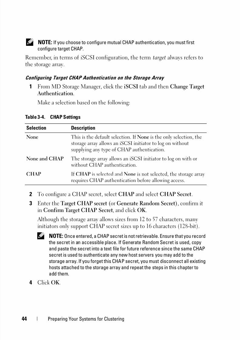
NOTE: If you choose to configure mutual CHAP authentication, you must first
configure target CHAP.
Remember, in terms of iSCSI configuration, the term target always refers tothe storage array.
Configuring Target CHAP Authentication on the Storage Array
1 From MD Storage Manager, click the iSCSI tab and then Change TargetAuthentication.
Make a selection based on the following:
2 To configure a CHAP secret, select CHAP and select CHAP Secret.
3 Enter the Target CHAP secret (or Generate Random Secret), confirm itin Confirm Target CHAP Secret, and click OK.
Although the storage array allows sizes from 12 to 57 characters, manyinitiators only support CHAP secret sizes up to 16 characters (128-bit).
NOTE: Once entered, a CHAP secret is not retrievable. Ensure that you record the secret in an accessible place. If Generate Random Secret is used, copy
and paste the secret into a text file for future reference since the same CHAP
secret is used to authenticate any new host servers you may add to the
storage array. If you forget this CHAP secret, you must disconnect all existing
hosts attached to the storage array and repeat the steps in this chapter to
add them.
4 Click OK.
Table 3-4. CHAP Settings
Selection Description
None This is the default selection. If None is the only selection, thestorage array allows an iSCSI initiator to log on withoutsupplying any type of CHAP authentication.
None and CHAP The storage array allows an iSCSI initiator to log on with orwithout CHAP authentication.
CHAP If CHAP is selected and None is not selected, the storage arrayrequires CHAP authentication before allowing access.

5/14/2018 MD32x0i With Windiws Faliover Clusters Hardware Installation Guide - slidepdf.com
http://slidepdf.com/reader/full/md32x0i-with-windiws-faliover-clusters-hardware-installation-guide 45/78
Preparing Your Systems for Clustering 45
Configuring Mutual CHAP Authentication on the Storage Array
The initiator secret must be unique for each host server that connects to the
storage array and must not be the same as the target CHAP secret.1 From MD Storage Manager, click on the iSCSI tab, then select Enter
Mutual Authentication Permissions.
2 Select an initiator on the host server and click the CHAP Secret.
3 Enter the Initiator CHAP secret, confirm it in Confirm initiator CHAPsecret, and click OK.
NOTE: In some cases, an initiator CHAP secret may already be defined in
your configuration. If so, use it here.
4 Click Close.
NOTE: To remove a CHAP secret, you must delete the host initiator and add it.
Configuring CHAP Authentication on the Host Server (Optional)
If you configured CHAP authentication in "Configuring CHAP Authentication on the Storage Array (Optional)" on page 43, complete thefollowing steps. If not, skip to "Configuring a Failover Cluster" on page 63.
To optionally configure CHAP authentication on the host server:
1 Click Start Programs Microsoft iSCSI Initiator.
2 If you are NOT using mutual CHAP authentication, skip to step 4.
3 If you are using mutual CHAP authentication:
a Click the General tab.
b Select Secret.
c At the Enter a secure secret window, enter the mutual CHAP secretyou entered for the storage array.
4 Click the Discovery tab.
5 Under Target Portals, select the IP address of the iSCSI port on the storagearray and click Remove.
The iSCSI port you configured on the storage array during target discoverymust disappear. You must reset this IP address under CHAPauthentication in the steps that immediately follow.
5/14/2018 MD32x0i With Windiws Faliover Clusters Hardware Installation Guide - slidepdf.com
http://slidepdf.com/reader/full/md32x0i-with-windiws-faliover-clusters-hardware-installation-guide 46/78
46 Preparing Your Systems for Clustering
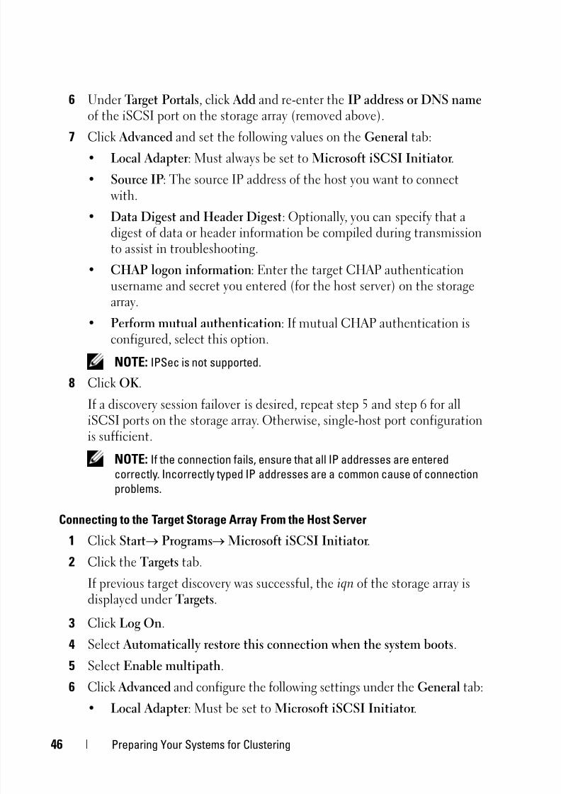
6 Under Target Portals, click Add and re-enter the IP address or DNS name of the iSCSI port on the storage array (removed above).
7 Click Advanced and set the following values on the General tab:• Local Adapter: Must always be set to Microsoft iSCSI Initiator.
• Source IP: The source IP address of the host you want to connectwith.
• Data Digest and Header Digest: Optionally, you can specify that adigest of data or header information be compiled during transmissionto assist in troubleshooting.
• CHAP logon information: Enter the target CHAP authenticationusername and secret you entered (for the host server) on the storagearray.
• Perform mutual authentication: If mutual CHAP authentication isconfigured, select this option.
NOTE: IPSec is not supported.
8 Click OK.
If a discovery session failover is desired, repeat step 5 and step 6 for all
iSCSI ports on the storage array. Otherwise, single-host port configurationis sufficient.
NOTE: If the connection fails, ensure that all IP addresses are entered
correctly. Incorrectly typed IP addresses are a common cause of connection
problems.
Connecting to the Target Storage Array From the Host Server
1 Click Start Programs Microsoft iSCSI Initiator.
2 Click the Targets tab.
If previous target discovery was successful, the iqn of the storage array isdisplayed under Targets.
3 Click Log On.
4 Select Automatically restore this connection when the system boots.
5 Select Enable multipath.
6 Click Advanced and configure the following settings under the General tab:• Local Adapter: Must be set to Microsoft iSCSI Initiator.
5/14/2018 MD32x0i With Windiws Faliover Clusters Hardware Installation Guide - slidepdf.com
http://slidepdf.com/reader/full/md32x0i-with-windiws-faliover-clusters-hardware-installation-guide 47/78
Preparing Your Systems for Clustering 47
• Source IP: The source IP address of the host server you want toconnect from.
• Target Portal: Select the iSCSI port on the storage array controllerthat you want to connect to.
• Data Digest and Header Digest: Optionally, you can specify that adigest of data or header information be compiled during transmissionto assist in troubleshooting.
• CHAP logon information: If CHAP authentication is required, selectthis option and enter the Target secret.
• Perform mutual authentication: If mutual CHAP authentication is
configured, select this option.
NOTE: IPSec is not supported.
7 Click OK.
To support storage array controller failover, the host server must beconnected to at least one iSCSI port on each controller. Repeat step 3 through step 8 for each iSCSI port on the storage array that you want toestablish as failover targets (the Target Portal address is different for each
port you connect to).The Status field on the Targets tab is displayed as Connected.
8 Click OK to close the Microsoft iSCSI initiator.
Viewing the Status of Your iSCSI Connections
In MD Storage Manager, click the iSCSI tab and then Configure iSCSI HostPorts to view the status of each iSCSI port you attempted to connect to andthe configuration state of all IP addresses. If either Disconnected or
Unconfigured is displayed, check the following and repeat the iSCSIconfiguration steps:
• Are all cables securely attached to each port on the host server andstorage array?
• Is TCP/IP correctly configured on all target host ports?
• Is CHAP set up correctly on both the host server and the storage array?

5/14/2018 MD32x0i With Windiws Faliover Clusters Hardware Installation Guide - slidepdf.com
http://slidepdf.com/reader/full/md32x0i-with-windiws-faliover-clusters-hardware-installation-guide 48/78
48 Preparing Your Systems for Clustering
Setting up In-Band Management (Optional)
Out-of-band management is the recommended method for managing the
storage array. However, to optionally set up in-band management, configurethe following:
Controller 0: IP: 192.168.128.101 Subnet Mask: 255.255.255.0
Controller 1: IP: 192.168.128.102 Subnet Mask: 255.255.255.0
NOTE: The management station you are using must be configured for network
communication to the same IP subnet as the PowerVault MD3200i or MD3220i iSCSI
host ports.
1 Establish an iSCSI session to the MD3200i or MD3220i RAID storagearray.
2 Restart the SMagent service.
3 Launch MD Storage Manager, and then click New.
NOTE: When you set up the first storage array management, the Add New
Storage Array window appears.
4 Select Manual and click OK.
5 Select In-band management and enter the host server name(s) orIP address(es) of the attached host that is running the MD StorageManager software.
6 Click Add.
In-band management is now successfully configured.
Configuring Host Access
If the host context agent is running on the host, the hosts and the host ports
connected to the storage array are automatically detected by MDSM andappear on the Mappings tab in the Array Management window.
If the host is not detected:
1 Launch MDSM.
2 Navigate to the Array Management window and click Manually DefineHosts.
3 In the Enter Host Name field, enter the host server for virtual diskmapping. This can be an informal name, not necessarily a name used toidentify the host server to the network.

5/14/2018 MD32x0i With Windiws Faliover Clusters Hardware Installation Guide - slidepdf.com
http://slidepdf.com/reader/full/md32x0i-with-windiws-faliover-clusters-hardware-installation-guide 49/78
Preparing Your Systems for Clustering 49
4 Select the relevant option in Do you plan to use the storage partitions inthe this storage array? field and click Next.
The Specify Host Port Identifiers window is displayed. NOTE: Select Yes if your cluster shares the array with other clustered or stand-
alone system(s), and No otherwise.
5 Select a method for adding the host port identifier.
6 Select the host type.
7 Select whether or not the host server must be part of a host server groupthat shares access to the same virtual disks as other host servers. Select Yes
only if the host is part of a Microsoft cluster.8 Click Next.
9 Specify if this host must be part of a host group.
10 Click Finish.
Creating a Host Group
A host group is a logical entity of two or more hosts that share access tospecific virtual disks on the storage array.
To create host groups:
1 In the Array Management window, select the Mappings tab.
2 In the Topology pane, select the storage array or the default group.
3 Perform one of the following actions:
– Select Mappings Define Host Group.
– Right-click the storage array or Default Group and select Define Host Group from the pop-up menu.
4 Type the name of the new host group in the Enter New Host Group Name field.
5 Select the appropriate hosts in the Select Hosts to Add Area field and clickAdd.
6 Click OK. The host group is added to the storage array.

5/14/2018 MD32x0i With Windiws Faliover Clusters Hardware Installation Guide - slidepdf.com
http://slidepdf.com/reader/full/md32x0i-with-windiws-faliover-clusters-hardware-installation-guide 50/78
50 Preparing Your Systems for Clustering
Creating Disk Groups and Virtual Disks
In some cases, the virtual disks may have been bound when the system was
shipped. However, it is important that you install the management softwareand verify that the desired virtual disk configuration exists.
You can manage your virtual disks remotely using PowerVault Modular DiskStorage Manager. A minimum of one virtual disk is required for anactive/passive cluster configuration and at least two virtual disks are requiredfor an active/active cluster configuration.
Disk groups are created in the non-configured capacity of a storage array andvirtual disks are created in the free capacity of a disk group. The hosts
attached to the storage array read and write data to the virtual disks. NOTE: Before you create virtual disks, you must first organize the physical disks
into disk groups and configure host access. You can then create virtual disks within
a disk group.
To create a virtual disk, use one of the following methods:
• Automatic Configuration
• Manual Configuration
Create disk groups using automatic configuration as follows:1 To start the Create Disk Group Wizard, perform one of these actions:
– To create a disk group from unconfigured capacity in the storagearray—On the Logical tab, select an Unconfigured Capacity node,and select Disk Group Create. Alternatively, you can right-click theUnconfigured Capacity node, and select Create Disk Group from thepop-up menu.
– To create a disk group from unassigned physical disks in the storage
array—On the Physical tab, select one or more unassigned physicaldisks of the same physical disk type, and select Disk Group Create. Alternatively, you can right-click the unassigned physical disks, andselect Create Disk Group from the pop-up menu.
– To create a secure disk group—On the Physical tab, select one or moreunassigned security capable physical disks of the same physical disktype, and select Disk Group Create. Alternatively, you can right-click the unassigned security capable physical disks, and select Create
Disk Group from the pop-up menu. The Create Disk Group windowis displayed.

5/14/2018 MD32x0i With Windiws Faliover Clusters Hardware Installation Guide - slidepdf.com
http://slidepdf.com/reader/full/md32x0i-with-windiws-faliover-clusters-hardware-installation-guide 51/78
Preparing Your Systems for Clustering 51
2 Click Next. The Disk Group Name and Physical Disk Selection window isdisplayed.
3 Type a name (up to 30 characters) for the disk group in Disk Group Name field.
4 Select the appropriate configuration method of Physical Disk selectionfrom the following:
– Automatic (see step 6)
– Manual (see step 7)
5 Click Next.
6 For automatic configuration, the RAID Level and Capacity window isdisplayed.
a Select the appropriate RAID level in the Select RAIDl Level field. Youcan select RAID levels 0, 1/10, 6, and 5. Depending on your RAID levelselection, the physical disks available for the selected RAID level isdisplayed in the Select Capacity table.
b In the Select Capacity table, select the relevant disk group capacityand click Finish.
7 For manual configuration, the Manual Physical Disk Selection window isdisplayed.
a Select the appropriate RAID level in Select RAID level. You can selectRAID levels 0, 1/10, 6, and 5. Depending on your RAID level selection,the physical disks available for the selected RAID level is displayed inUnselected Physical Disks table.
b In the Unselected Physical Disks table, select the appropriate physicaldisks and click Add.
NOTE: You can select multiple physical disks at the same time by holding <Ctrl> or
<Shift> and selecting additional physical disks.
8 Click Calculate Capacity to view the capacity of the new disk group.
9 Click Finish. A message is displayed confirming that the disk group issuccessfully created and that you must create at least one virtual diskbefore you can use the capacity of the new disk group.
To create virtual disks:
1 Choose one of these methods to start the Create Virtual Disk Wizard:

5/14/2018 MD32x0i With Windiws Faliover Clusters Hardware Installation Guide - slidepdf.com
http://slidepdf.com/reader/full/md32x0i-with-windiws-faliover-clusters-hardware-installation-guide 52/78
52 Preparing Your Systems for Clustering
– To create a virtual disk from unconfigured capacity in the storagearray—On the Logical tab, select an Unconfigured Capacity node
and select Virtual Disk
Create. Alternatively, you can right-click theUnconfigured Capacity node and select Create Virtual Disk from thepop-up menu.
– To create a virtual disk from free capacity on a disk group—On theLogical tab, select a Free Capacity node and select Virtual Disk Create. Alternatively, you can right-click the Free Capacity node andselect Create Virtual Disk from the pop-up menu.
– To create a virtual disk from unassigned physical disks in the storage
array—On the Physical tab, select one or more unassigned physicaldisks of the same physical disk type, and select Virtual Disk Create. Alternatively, right-click the unassigned physical disks, and selectCreate Virtual Disk from the pop-up menu.
– To create a secure virtual disk—On the Physical tab, select one ormore unassigned security capable physical disks of the same physicaldisk type, and select Virtual Disk Create. Alternatively, you canright-click the unassigned security capable physical disks and selectCreate Virtual Disk from the pop-up menu. If you chose an
Unconfigured Capacity node or unassigned physical disks to create avirtual disk, the Disk Group Required window is displayed. Click Yes and create a disk group by using the Create Disk Group Wizard. TheCreate Virtual Disk Wizard is displayed after you create the diskgroup. If you chose a Free Capacity node, the Create Virtual Diskwindow is displayed.
2 Click Next. The Specify Capacity /Name window is displayed.
3 Select the appropriate unit for memory from the Units drop-down list and
enter the capacity of the virtual disk in the New Virtual Disk Capacity field.
4 Enter a character name (up to 30 characters) for the virtual disk in theVirtual Disk Name field.
5 In the Advanced Virtual Disk Parameters field, you can select:
– Use recommended settings.
– Customize settings.
6 Click Next.

5/14/2018 MD32x0i With Windiws Faliover Clusters Hardware Installation Guide - slidepdf.com
http://slidepdf.com/reader/full/md32x0i-with-windiws-faliover-clusters-hardware-installation-guide 53/78
Preparing Your Systems for Clustering 53
7 In the Customize Advanced Virtual Disk Parameters window, select theappropriate Virtual Disk I/O Characteristics type from the following
options:– File system (typical)
– Database
– Multimedia
– Custom
NOTE: If you select Custom, you must select an appropriate segment size.
8 Select the appropriate Preferred RAID controller module.
For more information on how to create disk groups and virtual disks, see theDell PowerVault Modular Disk Storage Manager User’s Guide at support.dell.com/manuals.
It is recommended that you create at least one virtual disk for eachapplication. If multiple NTFS volumes are created on a single virtual diskusing Windows Disk Management, the volumes failover together, rather thanindividually from node-to-node.
NOTE: It is recommended that you use a RAID level other than RAID 0 (which is
commonly called striping). RAID 0 configurations provide very high performance,
but do not provide the level of availability required for the quorum resource. See the
documentation for your storage system for more information about setting up RAID
levels for the system.
Creating Host-to-Virtual Disk Mappings
Create host-to-virtual disk mappings to assign virtual disks to the host groupscontaining cluster nodes as follows:
1 In the Array Management window, select the Mappings tab.2 In the Topology pane, select:
– Default Group
– Undefined Mappings Node
– Individual Defined Mapping
– Host Group
– Host

5/14/2018 MD32x0i With Windiws Faliover Clusters Hardware Installation Guide - slidepdf.com
http://slidepdf.com/reader/full/md32x0i-with-windiws-faliover-clusters-hardware-installation-guide 54/78
54 Preparing Your Systems for Clustering
3 In the toolbar, select Mappings Define Additional Mapping. TheDefine Additional Mapping window is displayed.
4 Select the appropriate host group from the Host Group or Host field.5 In Logical Unit Number field, select a LUN. The supported LUNs are 0
through 255.
6 Select the virtual disk to be mapped in the Virtual Disk section. TheVirtual Disk section lists the names and capacity of the virtual disks thatare available for mapping based on the selected host group or selectedhost.
7 Click Add.
NOTE: The Add button is inactive until a host group or host, LUN, and virtual disk
are selected.
8 To define additional mappings, repeat step 4 through step 7.
NOTE: After a virtual disk has been mapped once, it is no longer available in the
Virtual Disk area.
9 Click Close. The mappings are saved. The Topology pane and the DefinedMappings pane in the Mappings tab are updated to display the mappings.
Troubleshooting Tools
The Dell PowerVault MDSM establishes communication with each managedarray and determines the current array status. When a problem occurs on astorage array, the MDSM provides several ways to troubleshoot the problem.
Event Log
You can use the Event Log Viewer to view a detailed list of events that occur
in a storage array. The event log is stored on reserved areas on the storage arraydisks. It records configuration events and storage array component failures.
CAUTION: Use this option only under the guidance of your Technical Supportrepresentative.
The event log stores approximately 8000 events before it replaces an eventwith a new event. If you want to keep a record of the events, you may savethem or else clear them from the event log.
The event log window shows the following types of event views:
• Summary view—Shows an event summary in a table form.

5/14/2018 MD32x0i With Windiws Faliover Clusters Hardware Installation Guide - slidepdf.com
http://slidepdf.com/reader/full/md32x0i-with-windiws-faliover-clusters-hardware-installation-guide 55/78
Preparing Your Systems for Clustering 55
• Detail view—Shows details about a selected event.
To view the event log:
1 In the Array Management window, select Advanced Troubleshooting View Event Log. The Event Log is displayed. By default, the summaryview is displayed.
2 Select View Details to view the details of each selected log entry. A Detail pane is added to the event log that contains information about the logitem. You can view the details of a single log entry at a time.
3 To save the event log:
aClick Save As. The Save Events dialog box is displayed.
b Navigate to the relevant folder and enter the relevant file name.
c Click Save.
4 Click Clear All to erase all log entries from the event log.
5 Click Close to exit the event log.
For more information, see the PowerVault Modular Disk Storage Manageronline help topics.
Recovery Guru
The Recovery Guru is a component of MDSM that diagnoses critical eventson the storage array and recommends step-by-step recovery procedures toresolve problems.
To display the Recovery Guru window in the Array Management window,perform one of the following actions:
• Click Recovery Guru.
• In the Support tab, click Recover from Failure.
• From the Status pane on the Summary tab, click Storage Array NeedsAttention.
You can detect a problem using the following indicators:
• Non-Optimal status icons
• Alert notification messages that are sent to the appropriate destinations
• Hardware indicator lights
The status icons return to Optimal status when problems are resolved.

5/14/2018 MD32x0i With Windiws Faliover Clusters Hardware Installation Guide - slidepdf.com
http://slidepdf.com/reader/full/md32x0i-with-windiws-faliover-clusters-hardware-installation-guide 56/78
56 Preparing Your Systems for Clustering
Storage Profile
The storage array profile provides a description of all components and
properties of the storage array. The storage array profile also provides theoption to save the storage array profile information in a text file. You can alsouse the storage array profile as an aid during recovery or as an overview of thecurrent configuration of the storage array. Create a new copy of the storagearray profile if your configuration changes.
1 To open the storage array profile in the Array Management window,perform one of the following actions:
– Select Storage Array View Profile.
– Select the Summary tab and click Storage Array Profile in the Status area.
– Select the Support tab and click View Storage Array Profile.
The Storage Array Profile screen is displayed. The Storage Array Profile screen contains several tabs, and the title of each tab corresponds to thesubject of the information contained.
2 Perform one of these actions in the Storage Array Profile screen:
– View detailed information – Go to step 3.– Search the storage array profile – Go to step 4.
– Save the storage array profile – Go to step 5.
– Close the storage array profile – Go to step 6.
3 Select one of the tabs, and use the horizontal scroll bar and the verticalscroll bar to view the storage array profile information. You can use othersteps in this procedure to search the storage array profile, to save the
storage array profile, or to close the storage array profile.4 To search the storage array profile, perform these steps:
a Click Find.
b In the Find text box, type the term that you want to search. If theterm is located on the current tab, it is highlighted in the storage arrayprofile information.
NOTE: The search is limited to the current tab. If you want to search for the term in
other tabs, select the tab and click the Find button again.

5/14/2018 MD32x0i With Windiws Faliover Clusters Hardware Installation Guide - slidepdf.com
http://slidepdf.com/reader/full/md32x0i-with-windiws-faliover-clusters-hardware-installation-guide 57/78
Preparing Your Systems for Clustering 57
c Click the Find button again to search for additional occurrences of theterm.
5 To save the storage array profile, perform these steps:a Click Save As.
b To save all sections of the storage array profile, select All Sections.
c To save information from particular sections of the storage arrayprofile, select the Select Sections option and click on the check boxescorresponding to the sections that you want to save.
d Select an appropriate directory.
e In File Name field, type a file name of your choice. To associate thefile with a particular software application that opens it, specify a fileextension, for example .txt.
NOTE: The file is saved as ASCII text.
f Click Save.
6 To exit the storage array profile, click Close.
Status Icons
Status icons identify the six possible health status conditions of the storagearray. For every non-optimal status icon, use the Recovery Guru to detect andtroubleshoot the problem. The six possible health status conditions aredescribed below:
• Optimal—Every component in the managed array is in the desiredworking condition.
• Needs Attention—A problem exists with the managed array that requires
intervention to correct it.• Fixing—A Needs Attention condition has been corrected and the managed
array is currently changing to an Optimal status.
• Unresponsive—The storage management station cannot communicatewith the array, one controller, or both controllers in the storage array. Waitat least five minutes for the storage array to return to an Optimal statusfollowing a recovery procedure.
• Unsupported—The node is not supported by this version of MDSM.

5/14/2018 MD32x0i With Windiws Faliover Clusters Hardware Installation Guide - slidepdf.com
http://slidepdf.com/reader/full/md32x0i-with-windiws-faliover-clusters-hardware-installation-guide 58/78
58 Preparing Your Systems for Clustering
• Software Unsupported—The storage array is running a level of softwarethat is no longer supported by MDSM.
Configuring the RAID Level for the Shared Storage Subsystem
The virtual disks in your shared storage subsystem must be configured intodisk groups or virtual disks using the Dell PowerVault MDSM software. Allvirtual disks, especially if they are used for the quorum resource, must bebound and must incorporate the appropriate RAID level to ensure highavailability.
NOTE: It is recommended that you use a RAID level other than RAID 0 (which is
commonly called striping). RAID 0 configurations provide very high performance,
but do not provide the level of availability required for the quorum resource. See the
documentation for your storage system for more information about setting up RAID
levels for your system.
Windows Operating System and Dynamic Volumes
The Windows operating system does not support dynamic disks (upgradeddisks) or volumes as shared cluster storage. If the shared cluster storage isconfigured as a dynamic disk, the Cluster Configuration wizard is not able to
discover the disks, preventing the cluster and network clients from accessingthe disks.
Assigning Drive Letters and Mount Points
A mount point is a drive attached to an empty folder on an NTFS volume. Amount point functions the same as a normal drive but is assigned a label orname instead of a drive letter. Using mount points, a cluster can support moreshared disks than the number of available drive letters.
The cluster installation procedure does not automatically add the mountpoint into the disks managed by the cluster. To add the mount point to thecluster, create a physical disk resource in the cluster resource group for eachmount point. Ensure that the new physical disk resource is in the same clusterresource group and is dependent on the root disk (that is, the disk from whichthe mount point is attached).
NOTE: When mounting a drive to an NTFS volume, do not create mount points from
the quorum resource or between the clustered disks and the local disks. Mount
points must be in the same cluster resource group and must be dependent on the
root disk.

5/14/2018 MD32x0i With Windiws Faliover Clusters Hardware Installation Guide - slidepdf.com
http://slidepdf.com/reader/full/md32x0i-with-windiws-faliover-clusters-hardware-installation-guide 59/78
Preparing Your Systems for Clustering 59
Naming and Formatting Drives on the Shared Storage System
Each virtual disk being created in the PowerVault Modular Disk Storage
Manager becomes a physical disk in Windows Disk Management. For eachphysical disk, perform the following:
• Write the disk signature
• Create the partition
• Assign the drive letter
• Format the partition with NTFS
CAUTION: The drive letters are manually assigned from the second node, the
shared disks are simultaneously accessible from both nodes. To ensure file systemintegrity and prevent possible data loss before you install the Microsoft Failover
Clustering software, prevent any I/O activity to the shared drives by performing thefollowing procedure on one node at a time and ensuring that the other node is shut
down.
The number of drive letters required by individual servers in a cluster mayvary. It is recommended that the shared drives be named in reversealphabetical order beginning with the letter z. To assign drive letters andformat drives on the shared storage system, perform the following steps:
1 Turn off node 2 and open Disk Management on node 1.
2 Allow Windows to enter a signature on all new physical or logical drives.
NOTE: Do not upgrade or convert your disks to dynamic disks.
3 Locate the icon for the first unnamed, unformatted drive on the sharedstorage system.
4 Right-click the icon and select Create from the submenu. If theunformatted drives are not visible, verify the following:
• The iSCSI Initiator target connections are active.
• The LUNs have been assigned to the hosts.
• The storage system is properly cabled to the servers.

5/14/2018 MD32x0i With Windiws Faliover Clusters Hardware Installation Guide - slidepdf.com
http://slidepdf.com/reader/full/md32x0i-with-windiws-faliover-clusters-hardware-installation-guide 60/78
60 Preparing Your Systems for Clustering
5 In the dialog box, create a partition with the size of the entire drive (thedefault) and then click OK.
NOTE: A virtual disk that is mapped or assigned from the storage system to acluster node(s) is represented as a physical disk within the Windows
operating system on each node. Microsoft Cluster allows only one node to
access a given physical disk resource at a time. Therefore, if a disk is
partitioned and contains multiple NTFS volumes, concurrent access to
different volumes is only possible from the cluster node controlling the
physical disk resource. If two NTFS volumes need to be controlled by different
nodes, these volumes must reside on separate disks.
6 Click Yes to confirm the partition.
7 With the mouse pointer on the same icon, right-click and select ChangeDrive Letter and Path from the submenu.
8 Assign a drive letter to an NTFS volume or create a mount point.
To assign a drive letter to an NTFS volume:
a Click Edit and select the letter you want to assign to the drive (forexample, z).
b Click OK.
c Go to step 9.
To create a mount point:
a Click Add.
b Click Mount in the following empty NTFS folder.
c Type the path to an empty folder on an NTFS volume, or click Browse to locate it.
d Click OK.e Go to step 9.
9 Click Yes to confirm the changes.
10 Right-click the drive icon again and select Format from the submenu.
11 Under Volume Label, enter a descriptive name for the new volume; forexample, Disk_Z or Email_Data.
5/14/2018 MD32x0i With Windiws Faliover Clusters Hardware Installation Guide - slidepdf.com
http://slidepdf.com/reader/full/md32x0i-with-windiws-faliover-clusters-hardware-installation-guide 61/78
Preparing Your Systems for Clustering 61
12 In the dialog box, change the file system to NTFS, select Quick Format,and click the Start button.
NOTE: The NTFS file system format is required for shared-disk resourcesunder Microsoft Cluster.
13 Click OK at the warning.
14 Click OK to acknowledge that the format is complete.
15 Click Close to close the dialog box.
16 Repeat step 3 through step 15 for each remaining drive.
17 Close Disk Management.
18 Turn off node 1.
19 Turn on node 2.
20 On node 2, open Disk Management.
21 Ensure that the drive letters for node 2 are correct and re-assign thedrive letters, if necessary. To re-assign the drive letters, repeat step 7 through step 9.
Using Advanced (Premium) PowerVault Modular Disk Storage Manager Features
PowerVault Modular Disk Storage Manager includes the following advancedfeatures:
• Snapshot Virtual Disk
• Virtual Disk Copy
To install and enable these premium features, you must purchase a featurekey file for each feature and then specify the storage array that must hostthem. For instructions about this process, see the Premium Feature Activation
card that shipped along with your Dell PowerVault MD3200i or MD3220istorage system.
These premium features increase the high availability for your clustersolution. It is essential that you follow the instructions below to ensure propercluster operations.
5/14/2018 MD32x0i With Windiws Faliover Clusters Hardware Installation Guide - slidepdf.com
http://slidepdf.com/reader/full/md32x0i-with-windiws-faliover-clusters-hardware-installation-guide 62/78
62 Preparing Your Systems for Clustering
Snapshot Virtual Disk
Snapshot Virtual Disk captures point-in-time images of a virtual disk for
backup, testing, or data processing without affecting the contents of thesource virtual disk. You can use either Simple Path or Advanced Path tocreate a snapshot for your cluster disk. The Snapshot Virtual Disk can bemapped to the primary node (the node owning the source disk) or thesecondary node (the node not owning the source disk) for backup, testing, ordata processing.
CAUTION: Avoid mapping the Snapshot Virtual Disk to more than one node in the
cluster at any point of time. The Snapshot Virtual Disk is not managed by FailoverCluster Manager, so mapping the Snapshot Virtual Disk to the host group or bothnodes in the cluster may allow both nodes to access data concurrently and thus
cause data corruption.
You can use a Microsoft Volume Shadow-copy Service (VSS) application tocreate and map snapshots. If you are using MDSM instead, you must followthe procedures described below.
To map the Snapshot Virtual Disk to the primary node:
1 Use Host-to-Virtual Disk Mapping in the Modular Disk Storage Manager.
This ensures that a different disk signature is assigned properly to theSnapshot Virtual Disk.
2 Use Windows Disk Management to re-scan for the Snapshot Virtual Disk,assign the drive letter, and start accessing the drive.
NOTE: The disks may be re-scanned several times for the Snapshot Virtual
Disk to be detected by Windows Disk Management. If the Snapshot Virtual
Disk is not detected, wait for a few minutes and re-scan the disks. Repeat the
process until the Snapshot Virtual Disk is detected; do not reboot the server.
If you need to map the Snapshot Virtual Disk to the secondary node (thenode not owning the source disk), you must map the Snapshot Virtual Disk tothe primary node first, to ensure that the snapshot is assigned a new disksignature. Then, use Modular Disk Storage Manager to unmap the SnapshotVirtual Disk from the primary node, map it to the secondary node, and startaccessing it.
CAUTION: Attempts to map the Snapshot Virtual Disk to the secondary node, prior to obtaining the signature from the primary node, may cause the operating system to misidentify the Snapshot Virtual Disk as an existing system volume and that may
result in data loss or an inaccessible Snapshot Virtual Disk.

5/14/2018 MD32x0i With Windiws Faliover Clusters Hardware Installation Guide - slidepdf.com
http://slidepdf.com/reader/full/md32x0i-with-windiws-faliover-clusters-hardware-installation-guide 63/78
Preparing Your Systems for Clustering 63
NOTE: For a cluster configuration with multiple Snapshot Virtual Disks, each virtual
disk must be mapped to the node owning the associated source disk first. The
primary node for a Snapshot Virtual Disk may not be the primary node for another
Snapshot Virtual Disk.
Virtual Disk Copy
Virtual Disk Copy generates a full copy of data from the source virtual disk tothe target virtual disk in a storage array. You can use Virtual Disk Copy to backup data, copy data from disk groups that use smaller-capacity physical disks todisk groups using greater-capacity physical disks, or restore Snapshot VirtualDisk data to the source virtual disk.
To create a Virtual Disk Copy of a Microsoft Cluster shared disk:
1 Create a Snapshot Virtual Disk using the cluster shared disk as a sourcedisk.
2 Do not map that Snapshot Virtual Disk to any cluster node. Then, usethe newly created Snapshot Virtual Disk as the source disk for theVirtual Disk Copy.
NOTE: When you attempt to create a Virtual Disk Copy of a Microsoft Cluster
shared disk directly, the operation fails and displays the following error:
The operation cannot complete because the selected
virtual disk is not a source virtual disk candidate.
If the cluster shared disk fails and you need to restore it from the target virtualdisk, use Failover Cluster Manager to change the status of the cluster groupcontaining the failed disk to offline, and then use one of the followingmethods:
1 Use Virtual Disk Copy to transfer the data from the target virtual disk tothe cluster shared disk.
2 Unassign the cluster shared disk from the host group and then map thetarget virtual disk to the host group.
Configuring a Failover Cluster
You can configure the operating system services on your Windows Serverfailover cluster, after you have established the private and public networksand have assigned the shared disks from the storage array to the cluster nodes.The procedures for configuring the failover cluster are different depending onthe Windows Server operating system you use.

5/14/2018 MD32x0i With Windiws Faliover Clusters Hardware Installation Guide - slidepdf.com
http://slidepdf.com/reader/full/md32x0i-with-windiws-faliover-clusters-hardware-installation-guide 64/78
64 Preparing Your Systems for Clustering
For more information on deploying your cluster, see the Dell Failover Clusterswith Microsoft Windows Server 2008 Installation and Troubleshooting Guide at
support.dell.com/manuals.

5/14/2018 MD32x0i With Windiws Faliover Clusters Hardware Installation Guide - slidepdf.com
http://slidepdf.com/reader/full/md32x0i-with-windiws-faliover-clusters-hardware-installation-guide 65/78
Troubleshooting Tools 65
ATroubleshootingThis appendix provides troubleshooting information for your clusterconfigurations.
Table A-1 describes general cluster problems you may encounter and theprobable causes and solutions for each problem.
Table A-1. General Cluster Troubleshooting
Problem Probable Cause Corrective Action
The nodes cannotaccess the storagesystem, or the clustersoftware is notfunctioning with thestorage system.
The storage system is notcabled properly to thenodes or the cablingbetween the storagecomponents is incorrect.
Ensure that the cables areconnected properly from thenode to the storage system. See"Cabling Your Cluster Hardware"on page 15 for more information.
One of the cables is faulty. Replace the faulty cable.
Host Group or Host-to-
Virtual Disk Mappings isnot created correctly.
Verify the following:
• Host Group is created and thecluster nodes are added to theHost Group.
• Host-to-Virtual Disk Mappingis created and the virtual disksare assigned to the Host Groupcontaining the cluster nodes.
The CHAP password
entered is wrong.
If CHAP is used, enter correct
user name and password.
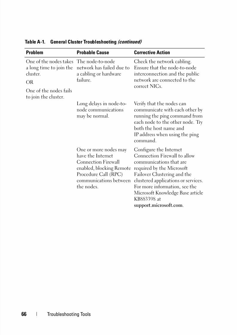
5/14/2018 MD32x0i With Windiws Faliover Clusters Hardware Installation Guide - slidepdf.com
http://slidepdf.com/reader/full/md32x0i-with-windiws-faliover-clusters-hardware-installation-guide 66/78
66 Troubleshooting Tools
One of the nodes takesa long time to join thecluster.
OR
One of the nodes failsto join the cluster.
The node-to-nodenetwork has failed due toa cabling or hardwarefailure.
Check the network cabling.Ensure that the node-to-nodeinterconnection and the publicnetwork are connected to thecorrect NICs.
Long delays in node-to-node communications
may be normal.
Verify that the nodes cancommunicate with each other by
running the ping command fromeach node to the other node. Tryboth the host name andIP address when using the pingcommand.
One or more nodes mayhave the InternetConnection Firewallenabled, blocking Remote
Procedure Call (RPC)communications betweenthe nodes.
Configure the InternetConnection Firewall to allowcommunications that arerequired by the Microsoft
Failover Clustering and theclustered applications or services.For more information, see theMicrosoft Knowledge Base articleKB883398 atsupport.microsoft.com.
Table A-1. General Cluster Troubleshooting (continued)
Problem Probable Cause Corrective Action
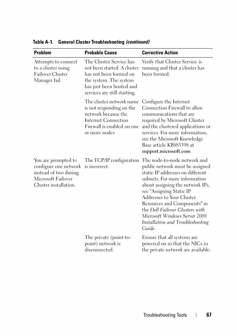
5/14/2018 MD32x0i With Windiws Faliover Clusters Hardware Installation Guide - slidepdf.com
http://slidepdf.com/reader/full/md32x0i-with-windiws-faliover-clusters-hardware-installation-guide 67/78
Troubleshooting Tools 67
Attempts to connectto a cluster usingFailover ClusterManager fail.
The Cluster Service hasnot been started. A clusterhas not been formed onthe system. The systemhas just been booted andservices are still starting.
Verify that Cluster Service isrunning and that a cluster hasbeen formed.
The cluster network nameis not responding on thenetwork because theInternet ConnectionFirewall is enabled on oneor more nodes
Configure the InternetConnection Firewall to allowcommunications that arerequired by Microsoft Clusterand the clustered applications orservices. For more information,see the Microsoft KnowledgeBase article KB883398 atsupport.microsoft.com
You are prompted toconfigure one networkinstead of two duringMicrosoft FailoverCluster installation.
The TCP/IP configurationis incorrect.
The node-to-node network andpublic network must be assignedstatic IP addresses on differentsubnets. For more informationabout assigning the network IPs,see "Assigning Static IP Addresses to Your ClusterResources and Components" inthe Dell Failover Clusters withMicrosoft Windows Server 2008Installation and TroubleshootingGuide.
The private (point-to-point) network isdisconnected.
Ensure that all systems arepowered on so that the NICs inthe private network are available.
Table A-1. General Cluster Troubleshooting (continued)
Problem Probable Cause Corrective Action

5/14/2018 MD32x0i With Windiws Faliover Clusters Hardware Installation Guide - slidepdf.com
http://slidepdf.com/reader/full/md32x0i-with-windiws-faliover-clusters-hardware-installation-guide 68/78
68 Troubleshooting Tools
Unable to add a nodeto the cluster.
The new node cannotaccess the shared disks.
Ensure that the new cluster nodecan enumerate the cluster disksusing Windows Disk Administration. If the disks donot appear in Disk Administration, check thefollowing:
• Check all cable connections
• Check the Access Controlsettings on the attachedstorage systems
One or more nodes mayhave the InternetConnection Firewallenabled, blocking RPCcommunications betweenthe nodes.
Configure the InternetConnection Firewall to allowcommunications that arerequired by the MicrosoftCluster and the clusteredapplications or services. For more
information, see the MicrosoftKnowledge Base articleKB883398 atsupport.microsoft.com.
Public network clientscannot access theapplications or servicesthat are provided bythe cluster.
One or more nodes mayhave the InternetConnection Firewallenabled, blocking RPCcommunications between
the nodes.
Configure the InternetConnection Firewall to allowcommunications that arerequired by the MicrosoftCluster and the clustered
applications or services.For more information, see theMicrosoft Knowledge Base articleKB883398 atsupport.microsoft.com.
Table A-1. General Cluster Troubleshooting (continued)
Problem Probable Cause Corrective Action

5/14/2018 MD32x0i With Windiws Faliover Clusters Hardware Installation Guide - slidepdf.com
http://slidepdf.com/reader/full/md32x0i-with-windiws-faliover-clusters-hardware-installation-guide 69/78
Troubleshooting Tools 69
Virtual Disk Copyoperation fails.
The Virtual Disk Copyoperation uses the clusterdisk as the source disk.
To perform a Virtual Disk Copyoperation on the cluster sharedisk, create a snapshot of thedisk, and then perform a VirtualDisk Copy of the snapshotvirtual disk.
Unable to assign thedrive letter to thesnapshot virtual disk.
Unable to access thesnapshot virtual disk.
System Error Logdisplays a warning withevent 59 from partmgr stating that thesnapshot virtual disk isa redundant path of a
cluster disk.
The snapshot virtual diskhas been erroneouslymapped to the node thatdoes not own the sourcedisk.
Unmap the snapshot virtual diskfrom the node not owning thesource disk, then assign it to thenode that owns the source disk.See Using Advanced (Premium)PowerVault Modular DiskStorage Manager Features formore information.
Table A-1. General Cluster Troubleshooting (continued)
Problem Probable Cause Corrective Action

5/14/2018 MD32x0i With Windiws Faliover Clusters Hardware Installation Guide - slidepdf.com
http://slidepdf.com/reader/full/md32x0i-with-windiws-faliover-clusters-hardware-installation-guide 70/78
70 Troubleshooting Tools
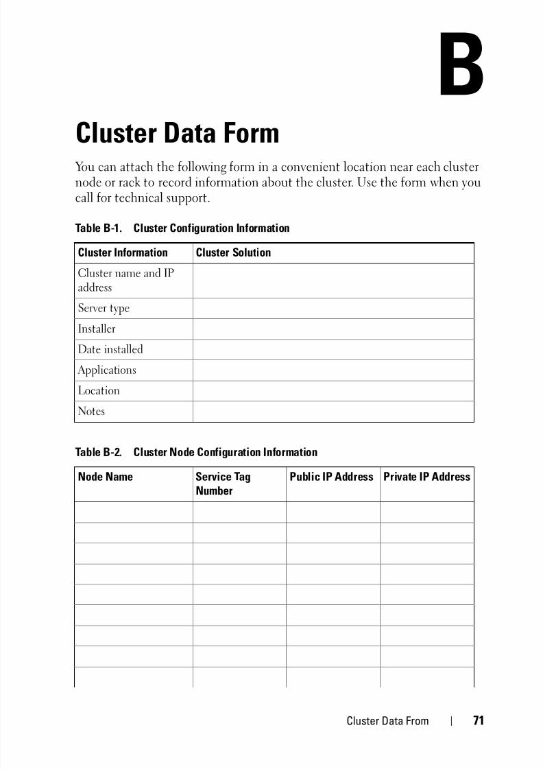
5/14/2018 MD32x0i With Windiws Faliover Clusters Hardware Installation Guide - slidepdf.com
http://slidepdf.com/reader/full/md32x0i-with-windiws-faliover-clusters-hardware-installation-guide 71/78
Cluster Data From 71
BCluster Data Form
You can attach the following form in a convenient location near each clusternode or rack to record information about the cluster. Use the form when youcall for technical support.
Table B-1. Cluster Configuration Information
Cluster Information Cluster Solution
Cluster name and IPaddress
Server type
Installer
Date installed
Applications
Location
Notes
Table B-2. Cluster Node Configuration Information
Node Name Service TagNumber
Public IP Address Private IP Address

5/14/2018 MD32x0i With Windiws Faliover Clusters Hardware Installation Guide - slidepdf.com
http://slidepdf.com/reader/full/md32x0i-with-windiws-faliover-clusters-hardware-installation-guide 72/78
72 Cluster Data From
Table B-3. Additional Network Information
Additional Networks
Table B-4. Storage Array Configuration Information
Array Array Service Tag IP Address Number of Attached DAEs Virtual Disks
1
2
3
4
Table B-2. Cluster Node Configuration Information
Node Name Service Tag
Number
Public IP Address Private IP Address

5/14/2018 MD32x0i With Windiws Faliover Clusters Hardware Installation Guide - slidepdf.com
http://slidepdf.com/reader/full/md32x0i-with-windiws-faliover-clusters-hardware-installation-guide 73/78
iSCSI Configuration Worksheet 73
CiSCSI Configuration WorksheetIPv4 Settings
Mutual CHAP
Secret
Target CHAPSecret
A
B
host server
PowerVault
MD32xx i
192.168.130.101 (In 0 default)
192.168.131.101 (In 1 default)
192.168.132.101 (In 2 default)
192.168.133.101 (In 3 default) 192.168.128.101 (management network port)
192.168.130.102 (In 0 default)
192.168.131.102 (In 1 default)
192.168.132.102 (In 2 default)
192.168.133.102 (In 3 default) 192.168.128.102 (management network port)
If you need additional space for more than one host server, use an additional sheet.
iSCSI port 1
iSCSI port 2
iSCSI port 3
iSCSI port 4
Management port
Management port
Static IP address (host server)Subnet
Default gateway(should be different for each NIC)
___ . ___ . ___ . ___
___ . ___ . ___ . ___
___ . ___ . ___ . ___
___ . ___ . ___ . ___
___ . ___ . ___ . ___
___ . ___ . ___ . ___
Static IP address (host server) Subnet Default gateway
iSCSI controller 0, In 0
iSCSI controller 0, In 1
iSCSI controller 0, In 2
iSCSI controller 0, In 3
Management port cntrl 0
iSCSI controller 1, In 0
iSCSI controller 1, In 1
iSCSI controller 1, In 2
iSCSI controller 1, In 3
Management port cntrl 1
___ . ___ . ___ . ___
___ . ___ . ___ . ___
___ . ___ . ___ . ___
___ . ___ . ___ . ___
___ . ___ . ___ . ___
___ . ___ . ___ . ___
___ . ___ . ___ . ___
___ . ___ . ___ . ___
___ . ___ . ___ . ___
___ . ___ . ___ . ___
___ . ___ . ___ . ___
___ . ___ . ___ . ___
___ . ___ . ___ . ___
___ . ___ . ___ . ___
___ . ___ . ___ . ___
___ . ___ . ___ . ___
___ . ___ . ___ . ___
___ . ___ . ___ . ___
___ . ___ . ___ . ___
___ . ___ . ___ . ___
___ . ___ . ___ . ___
___ . ___ . ___ . ___
___ . ___ . ___ . ___
___ . ___ . ___ . ___
___ . ___ . ___ . ___
___ . ___ . ___ . ___
___ . ___ . ___ . ___
___ . ___ . ___ . ___
___ . ___ . ___ . ___
___ . ___ . ___ . ___
___ . ___ . ___ . ___
___ . ___ . ___ . ___
___ . ___ . ___ . ___
___ . ___ . ___ . ___
___ . ___ . ___ . ___
___ . ___ . ___ . ___
___ . ___ . ___ . ___
___ . ___ . ___ . ___
___ . ___ . ___ . ___
___ . ___ . ___ . ___
___ . ___ . ___ . ___
___ . ___ . ___ . ___
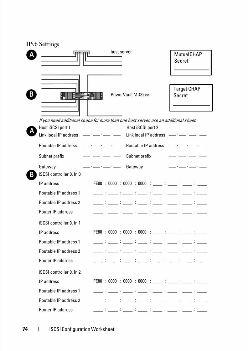
5/14/2018 MD32x0i With Windiws Faliover Clusters Hardware Installation Guide - slidepdf.com
http://slidepdf.com/reader/full/md32x0i-with-windiws-faliover-clusters-hardware-installation-guide 74/78
74 iSCSI Configuration Worksheet
IPv6 Settings
Mutual CHAP
Secret
Target CHAP
Secret
A
B
If you need additional space for more than one host server, use an additional sheet.
Link local IP address
Routable IP address
Subnet prefix
Gateway
A
host server
Host iSCSI port 1
___ . ___ . ___ . ___
___ . ___ . ___ . ___
___ . ___ . ___ . ___
___ . ___ . ___ . ___
Link local IP address
Routable IP address
Subnet prefix
Gateway
Host iSCSI port 2
___ . ___ . ___ . ___
___ . ___ . ___ . ___
___ . ___ . ___ . ___
___ . ___ . ___ . ___
iSCSI controller 0, In 0
IP address
Routable IP address 1
Routable IP address 2
Router IP address
B
iSCSI controller 0, In 1
IP address
Routable IP address 1
Routable IP address 2
Router IP address
iSCSI controller 0, In 2
IP address
Routable IP address 1
Routable IP address 2
Router IP address
FE80 : 0000 : 0000 : 0000 : ____ : ____ : ____ : ____
____ : ____ : ____ : ____ : ____ : ____ : ____ : ____
____ : ____ : ____ : ____ : ____ : ____ : ____ : ____
____ : ____ : ____ : ____ : ____ : ____ : ____ : ____
FE80 : 0000 : 0000 : 0000 : ____ : ____ : ____ : ____
____ : ____ : ____ : ____ : ____ : ____ : ____ : ____
____ : ____ : ____ : ____ : ____ : ____ : ____ : ____
____ : ____ : ____ : ____ : ____ : ____ : ____ : ____
FE80 : 0000 : 0000 : 0000 : ____ : ____ : ____ : ____
____ : ____ : ____ : ____ : ____ : ____ : ____ : ____
____ : ____ : ____ : ____ : ____ : ____ : ____ : ____
____ : ____ : ____ : ____ : ____ : ____ : ____ : ____
PowerVault MD32xx i

5/14/2018 MD32x0i With Windiws Faliover Clusters Hardware Installation Guide - slidepdf.com
http://slidepdf.com/reader/full/md32x0i-with-windiws-faliover-clusters-hardware-installation-guide 75/78
iSCSI Configuration Worksheet 75
iSCSI controller 0, In 3
IP address
Routable IP address 1
Routable IP address 2
Router IP address
FE80 : 0000 : 0000 : 0000 : ____ : ____ : ____ : ____
____ : ____ : ____ : ____ : ____ : ____ : ____ : ____
____ : ____ : ____ : ____ : ____ : ____ : ____ : ____
____ : ____ : ____ : ____ : ____ : ____ : ____ : ____
iSCSI controller 1, In 0
IP address
Routable IP address 1
Routable IP address 2
Router IP address
FE80 : 0000 : 0000 : 0000 : ____ : ____ : ____ : ____
____ : ____ : ____ : ____ : ____ : ____ : ____ : ____
____ : ____ : ____ : ____ : ____ : ____ : ____ : ____
____ : ____ : ____ : ____ : ____ : ____ : ____ : ____
iSCSI controller 1, In 1
IP address
Routable IP address 1
Routable IP address 2
Router IP address
FE80 : 0000 : 0000 : 0000 : ____ : ____ : ____ : ____
____ : ____ : ____ : ____ : ____ : ____ : ____ : ____
____ : ____ : ____ : ____ : ____ : ____ : ____ : ________ : ____ : ____ : ____ : ____ : ____ : ____ : ____
iSCSI controller 1, In 2
IP address
Routable IP address 1
Routable IP address 2
Router IP address
FE80 : 0000 : 0000 : 0000 : ____ : ____ : ____ : ____
____ : ____ : ____ : ____ : ____ : ____ : ____ : ____
____ : ____ : ____ : ____ : ____ : ____ : ____ : ____
____ : ____ : ____ : ____ : ____ : ____ : ____ : ____
iSCSI controller 1, In 3
IP address
Routable IP address 1
Routable IP address 2
Router IP address
FE80 : 0000 : 0000 : 0000 : ____ : ____ : ____ : ____
____ : ____ : ____ : ____ : ____ : ____ : ____ : ____
____ : ____ : ____ : ____ : ____ : ____ : ____ : ____
____ : ____ : ____ : ____ : ____ : ____ : ____ : ____

5/14/2018 MD32x0i With Windiws Faliover Clusters Hardware Installation Guide - slidepdf.com
http://slidepdf.com/reader/full/md32x0i-with-windiws-faliover-clusters-hardware-installation-guide 76/78
76 iSCSI Configuration Worksheet

5/14/2018 MD32x0i With Windiws Faliover Clusters Hardware Installation Guide - slidepdf.com
http://slidepdf.com/reader/full/md32x0i-with-windiws-faliover-clusters-hardware-installation-guide 77/78
Index 77
Index
A
advanced features
snapshot virtual disk, 10
virtual disk copy, 10
assigning
drive letters and mount points, 58
C
cabling
cluster in direct-attachedconfiguration, 21
cluster in network-attached
configuration, 24mouse, keyboard, and monitor, 15
power supplies, 15
storage systems, 21
CHAP, 42
mutual, 42
target, 42
cluster data form, 71cluster storage requirements, 8
configuring
failover cluster, 63
shared storage system, 37
configuring iSCSI
on the storage array, 38
E
event log, 54
I
initial storage array setup, 38installing
iSCSI NICs, 34
Microsoft iSCSI softwareinitiator, 35
installing and configuring
storage management software, 35
iSCSI, 37terminology, 37
iSCSI configuration
connect from host server, 46
in-band management, 48
set CHAP on host server, 45
iSCSI configuration worksheet
iPv4 settings, 73
iPv6 settings, 74
M
MSCS
installing and configuring, 48
multipath software, 9

5/14/2018 MD32x0i With Windiws Faliover Clusters Hardware Installation Guide - slidepdf.com
http://slidepdf.com/reader/full/md32x0i-with-windiws-faliover-clusters-hardware-installation-guide 78/78
78 Index
N
NIC teaming, 20
O
operating system
installing, 33
PPowerVault 22 xS storage system
clustering, 59
R
recovery guru, 55
S
snapshot virtual disk, 62
status icons, 57
storage profile, 56
supported cluster
configurations, 11
T
troubleshooting
general cluster, 65
V
virtual disk copy, 63
W
Windows Server 2003,Enterprise Edition
installing, 33