meadow burke technical manual reinforcing
TRANSCRIPT

ReinforcingMEADOW BURKE TECHNICAL MANUAL
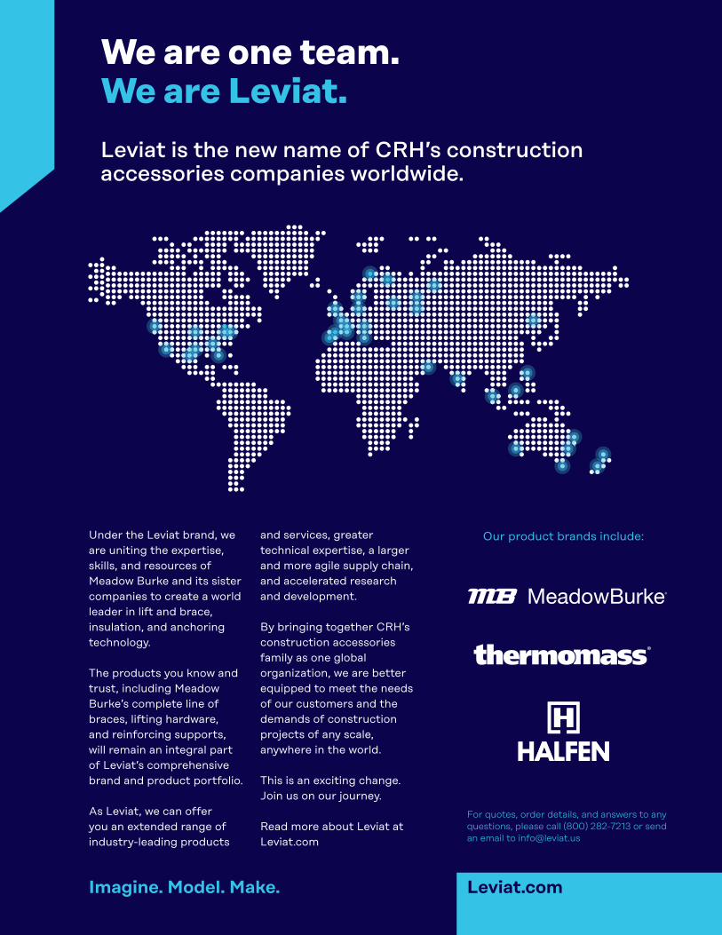
Under the Leviat brand, we are uniting the expertise, skills, and resources of Meadow Burke and its sister companies to create a world leader in lift and brace, insulation, and anchoring technology.
The products you know and trust, including Meadow Burke’s complete line of braces, lifting hardware, and reinforcing supports, will remain an integral part of Leviat’s comprehensive brand and product portfolio. As Leviat, we can offer you an extended range of industry-leading products
and services, greater technical expertise, a larger and more agile supply chain, and accelerated research and development.
By bringing together CRH’s construction accessories family as one global organization, we are better equipped to meet the needs of our customers and the demands of construction projects of any scale, anywhere in the world.
This is an exciting change. Join us on our journey. Read more about Leviat at Leviat.com
Leviat is the new name of CRH’s construction accessories companies worldwide.
We are one team. We are Leviat.
Imagine. Model. Make. Leviat.com
Our product brands include:
For quotes, order details, and answers to any questions, please call (800) 282-7213 or send an email to [email protected]

Rein
forc
ing
Bar
Supp
ort
Reba
r Sp
licin
g Pr
oduc
ts
3
MeadowBurke®Reinforcing Technical Manual
www.MeadowBurke.com
Metal Bar Supports .................................................................................................5-8 Slab Bolster ..................................................................................................................6 Slab Bolster - Upper .....................................................................................................6 Beam Bolster................................................................................................................6 Beam Bolster - Upper ...................................................................................................6 Continuous High Chair ..................................................................................................7 Continuous High Chair - Upper .....................................................................................7 Continuous High Chair - Metal Deck .............................................................................7 High Chair - Metal Deck ...............................................................................................7 High Chair ....................................................................................................................7 Bar Chair ......................................................................................................................8 Joist Chair ....................................................................................................................8 Joist Chair - Upper .......................................................................................................8 Continuous Support - Zig Zag .......................................................................................8 Wire Girder - Double.....................................................................................................8 Plastic Bar Supports .............................................................................................9-10 Tuff Plus SB - Slab Bolster ...........................................................................................9 Tuff Plus SBR - Slab Bolster with Runner .....................................................................9 Tuff Chair .....................................................................................................................9 Intersectional Chair.......................................................................................................9 Mesh Chair with Base...................................................................................................9 PC-2 Snap-On Mesh Chair..........................................................................................10 PC-3 Snap-On Mesh Chair with Base .........................................................................10 PC-4 Snap-On Paving Chair with Base .......................................................................10 PC-5 Snap-On Bar Chair.............................................................................................10 PW-11 Plaswheel .......................................................................................................10 PW-14 Unispacer........................................................................................................10 BC-2, BC-4 Bar Cap ...................................................................................................10
Threaded Splice System .....................................................................................11-16 Threaded Rebar Coupler - Smooth..............................................................................12 Threaded Rebar Coupler - Smooth / Flange................................................................12 Setting Bar Assemblies...............................................................................................13 Splice Bars .................................................................................................................14 Tension Splice Lap Length Data .................................................................................15 ZAP Screwlock®..........................................................................................................16
Reinforcing Bar Supports (Metal & Plastic)
Rebar Splicing Products
Table of Contents

MeadowBurke®Precast Technical Manual
www.MeadowBurke.com
4

Rein
forc
ing
Bar
Supp
ort
5
MeadowBurke®Reinforcing Bar Supports
www.MeadowBurke.com

6
MeadowBurke®Metal Reinforcing Bar Supports
www.MeadowBurke.com
METAL REINFORCING BAR SUPPORTS (SB) SLAB BOLSTER
(SBR) SLAB BOLSTER – UPPER
(BB) BEAM BOLSTER
5'-0"
SLAB BOLSTER DATA
Available Height
Leg Spacing (c/c)
3/4" to 3"SB 5"
LengthType
Meadow Burke metal reinforcing bar supports can be manufactured in compliance with American Concrete Institute (ACI) ACI-SP-66, ACI-315 and ACI-315R. Quality rebar metal supports are available in the following CRSI Classification for finishes: Class 1A – Epoxy coated. Class 2 (A or B) – Manufactured with Stainless steel legs. Class 3 – Plain wire, no protection. Also available: Epoxy coated meeting AASHTO specifications. Epoxy coated with plastic dipped feet. Complete plastic coating (100% encapsulate) up to 3” heights. (not available for the Slab Bolster) Notes: Stainless steel utilized by Meadow Burke in the manufacture of rebar supports conforms to ASTM A-493 and AISI Type 430 and may display some magnetic qualities which shall not be cause for rejection. Heights available in 1/4” increments.
SLAB BOLSTER - UPPER DATA
BEAM BOLSTER DATA
To Order, Specify: quantity, type, height and finish classification.
To Order, Specify: quantity, type, height and finish classification.
To Order, Specify: quantity, type, height and finish classification.
5'-0"
Available Height
Leg Spacing (c/c)
3/4" to 3"SBR 5"
LengthType
5'-0"
Available Height
Leg Spacing (c/c)
1" to 5"BB 2-1/2"
LengthType
(BBU) BEAM BOLSTER – UPPER
BEAM BOLSTER - UPPER DATA
To Order, Specify: quantity, type, height and finish classification.
5'-0"
Available Height
Leg Spacing (c/c)
BBU 2-1/2"
LengthType
1" to 5"

Rein
forc
ing
Bar
Supp
ort
7
MeadowBurke®Metal Reinforcing Bar Supports
www.MeadowBurke.com
(CHC) CONTINUOUS HIGH CHAIR
(CHCU) CONTINUOUS HIGH CHAIR – UPPER
(CHCM) CONTINUOUS HIGH CHAIR – METAL DECK
CONTINUOUS HIGH CHAIR DATA
CONTINUOUS HIGH CHAIR - UPPER DATA
CONTINUOUS HIGH CHAIR - METAL DECK DATA
To Order, Specify: quantity, type, height and finish classification.
To Order, Specify: quantity, type, height and finish classification.
To Order, Specify: quantity, name, type A or B, leg spread, height.
5'-0"
Available Height
Leg Spacing (c/c)
CHC 7-1/2"
LengthType
5'-0"
Available Height
Leg Spacing (c/c)
CHCU 2" to 20" 7-1/2"
LengthType
5'-0"
Available Height
Leg Spacing (c/c)
Type A 1" to 5"
2" to 20"
7-1/2"
5'-0"Type B 1" to 5" Varies
LengthCHCM
(HCMD) HIGH CHAIR – METAL DECK
HIGH CHAIR - METAL DECK DATA
To Order, Specify: quantity, name, type, A, B and C dimension. To insure accuracy of order please include metal deck profile.
1/4"
Available Height
Type A or B
Height IncrementsHCMD
2" to 15"
Type A
Type B
Type A
Type B
AB
C
AB
C(HC) HIGH CHAIR
Available HeightType Height
Increments
2" to 40"HC 1/4"
To Order, Specify: quantity, type, height and finish classification.
HIGH CHAIR DATA
(Available with metal or plastic sand plate)

8
MeadowBurke®Metal Reinforcing Bar Supports
www.MeadowBurke.com
(BC) BAR CHAIR (JC) JOIST CHAIR
To Order, Specify: quantity, type, height and finish classification.
To Order, Specify: quantity, type, height and finish classification.
Available HeightType Height
Increments
3/4" to 2"BC 1/4"
BAR CHAIR DATA
Available HeightType Height
Increments
3/4" to 2"JC 1/4"
JOIST CHAIR DATA
(UJC) JOIST CHAIR – UPPER
To Order, Specify: quantity, type, height and finish classification.
Span
HeightAvailable HeightType SPAN
-1" to +3-1/2"UJC 14"
JOIST CHAIR - UPPER DATA
8'-0"
CONTINUOUS SUPPORT (ZIG-ZAG) DATA
Type Available Height
Height Increments
2" to 12"CS 1/4"
Length
To Order, Specify: quantity, type, height and finish classification.
(CS) CONTINUOUS SUPPORT (ZIG-ZAG) CS Continuous Support (Zig-Zag) is a steel support for horizontal wire mesh, structural fabric or reinforcing bars and an excellent spacer for vertical steel in concrete walls. The support is very stable, it will not slide or tip and has excellent load carrying capacity. It is easy to install and can be bent around voids and/or partitions.
WIRE GIRDER – DOUBLE The Wire Girder – Double is designed to quickly and accurately position wire mesh in large slab-on-grade applications. The girder is available in heights from 3" to 9" in 1" increments and in lengths up to 40'. Optional snap-on sand plates are available for use on sandy soils to prevent the girder from turning during concrete placement. When using on a firm casting bed, the snap-on plates are not a necessity but will give better support on slabs exceeding 6" in thickness. The optional snap-on plates are field installed by simply squeezing the bottom runners of the girder inward until they slip inside the plate tabs. Release of the runners will let them slide under the tabs and be held firmly in place by the tabs. To Order Specify: quantity, type, height & length. To Order Optional Snap-On Plate, Specify: quantity and type.

Rein
forc
ing
Bar
Supp
ort
9
MeadowBurke®Plastic Reinforcing Bar Supports
www.MeadowBurke.com
TUFF PLUS SB – SLAB BOLSTER The Tuff Plus SB is a composite slab bolster that is used to provide accurate cover for lower mats of steel reinforcement in concrete elements. Suitable for a wide range of uses, the Tuff Plus SB-slab bolster can be used in Tilt-Up Concrete Construction, Precast Concrete Construction, Post Tensioned Concrete and other Cast in place applications. The Tuff Plus SB, all plastic slab bolster, may also be used as side form spacers in vertical formwork. The Tuff Plus SB slab bolster is fabricated from fiber filled gray composite material designed to blend with the concrete surface, if exposed. Top bar corrugations are placed on 1” centers to visually aid rebar placement. The Tuff Plus SB plastic slab bolster is manufactured in true 60” lengths, eliminating assembly and expedites field placement. TUFF PLUS SBR – SLAB BOLSTER with RUNNER The Tuff Plus SBR Slab Bolster with Runner, is typically used to provide accurate and efficient place-ment of upper mats of steel reinforcement in concrete elements. The Tuff Plus SBR is a composite slab bolster upper that can be used in Bridge, Tilt-up, Precast, Post Tension and other segments of concrete construction. The Tuff Plus SBR Slab Bolster Upper, is fabricated from fiber filled composite material. Top bar cor-rugations are located at 1” centers to aid in rebar placement. The Tuff Plus SBR with Runner is a direct replacement for metal slab bolster upper. X-TUFF SLAB BOLSTER X Tuff Slab Bolster is a new rebar support manufactured in the U.S. using high-performance PC/ABS plastic for best-in-class strength and durability. MB TUFF CHAIR MB Tuff Chair is engineered for strength, durability, recoverability and consistent ruggedness, and are available in a range of heights from 3/4" to 10”. (IC) INTERSECTIONAL CHAIR The IC Intersectional Chair or is designed for use at the intersection of two crossing lengths of post tensioning cable rebar to correctly position and firmly hold the two bars in place. The large support base gives added benefit when used on vapor barriers or soft fill. The chair fits 1/2" PT cable or up to #5 rebar, and is available in most heights from 1-1/2" to 7" in 1/2" increments. (MBCB) MESH BAR CHAIR WITH BASE The Mesh Bar Chair with Base (MBCB) is a light duty, composite chair with sand plate for use on soft surfaces and/or slab on grade to correctly position and hold the wire mesh securely in place. Each size chair is designed to service two mesh positioning heights. It is available in heights from 5/8" to 6". It can be used to support up to a #5 rebar. To order any of these products, specify: quantity, type and height.
10
MeadowBurke®Plastic Reinforcing Bar Supports
www.MeadowBurke.com
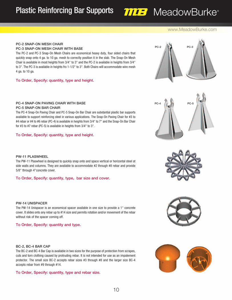
PC-2 SNAP-ON MESH CHAIR PC-3 SNAP-ON MESH CHAIR WITH BASE The PC-2 and PC-3 Snap-On Mesh Chairs are economical heavy duty, four sided chairs that quickly snap onto 4 ga. to 10 ga. mesh to correctly position it in the slab. The Snap-On Mesh Chair is available in most heights from 3/4" to 3" and the PC-2 is available in heights from 3/4" to 3". The PC-3 is available in heights fro 1-1/2" to 3". Both Chairs will accommodate wire mesh 4 ga. to 10 ga. To Order, Specify: quantity, type and height. PC-4 SNAP-ON PAVING CHAIR WITH BASE PC-5 SNAP-ON BAR CHAIR The PC-4 Snap-On Paving Chair and PC-5 Snap-On Bar Chair are substantial plastic bar supports available to support reinforcing steel in various applications. The Snap-On Paving Chair for #3 to #4 rebar or #4 to #6 rebar (PC-4) is available in heights from 3/4" to 7" and the Snap-On Bar Chair for #3 to #7 rebar (PC-5) is available in heights from 3/4" to 3". To Order, Specify: quantity, type and height. PW-11 PLASWHEEL The PW-11 Plaswheel is designed to quickly snap onto and space vertical or horizontal steel at side walls and columns. They are available to accommodate #2 through #8 rebar and provide 5/8" through 4"concrete cover. To Order, Specify: quantity, type, bar size and cover. PW-14 UNISPACER The PW-14 Unispacer is an economical spacer available in one size to provide a 1" concrete cover. It slides onto any rebar up to #14 size and permits rotation and/or movement of the rebar without risk of the spacer coming off. To Order, Specify: quantity and type. BC-2, BC-4 BAR CAP The BC-2 and BC-4 Bar Cap is available in two sizes for the purpose of protection from scrapes, cuts and torn clothing caused by protruding rebar. It is not intended for use as an impalement protector. The small size BC-2 accepts rebar sizes #3 through #8 and the larger size BC-4 accepts rebar from #9 through #14. To Order, Specify: quantity, type and rebar size.
PC-2 PC-3
PC-4 PC-5

Reba
r Sp
licin
g Pr
oduc
ts
11
MeadowBurke®Rebar Splicing Products
www.MeadowBurke.com
12
MeadowBurke®Rebar Splicing Products
www.MeadowBurke.com
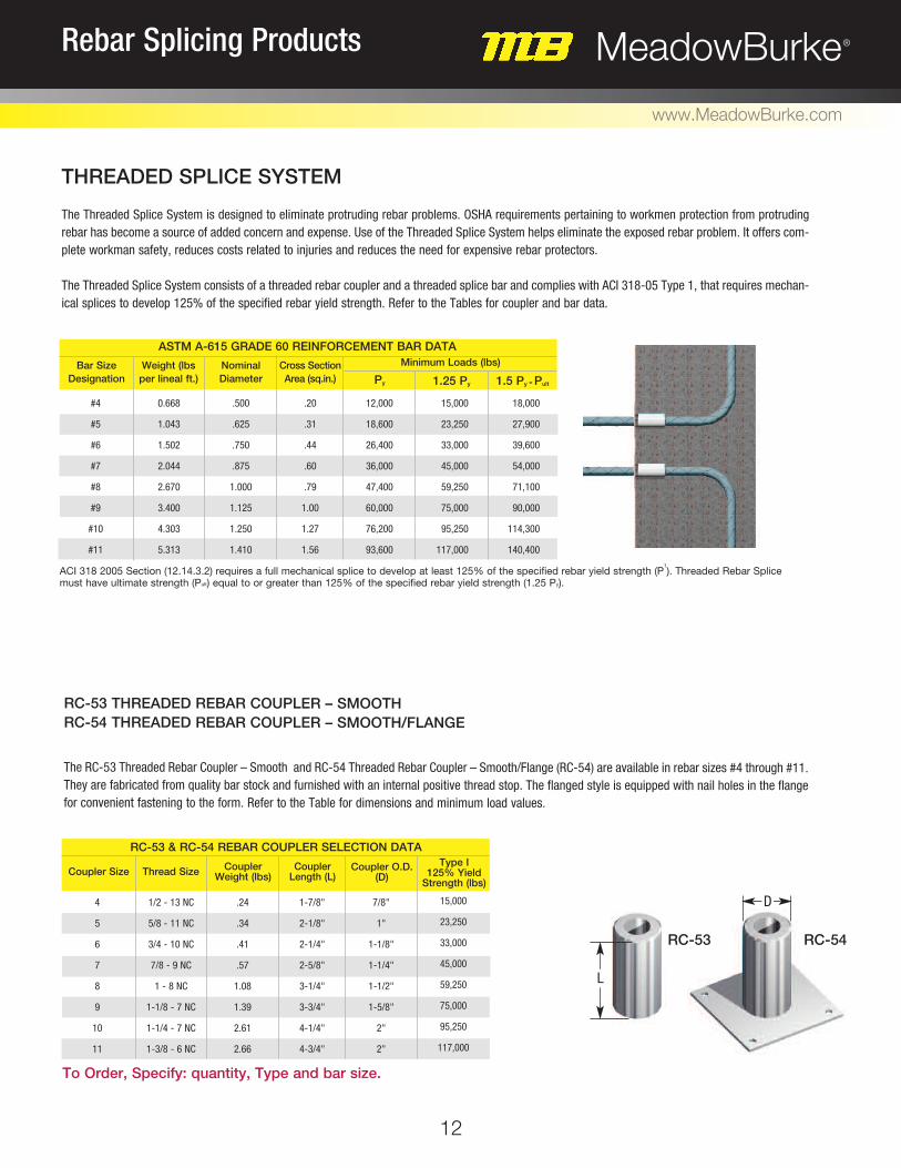
THREADED SPLICE SYSTEM The Threaded Splice System is designed to eliminate protruding rebar problems. OSHA requirements pertaining to workmen protection from protruding rebar has become a source of added concern and expense. Use of the Threaded Splice System helps eliminate the exposed rebar problem. It offers com-plete workman safety, reduces costs related to injuries and reduces the need for expensive rebar protectors. The Threaded Splice System consists of a threaded rebar coupler and a threaded splice bar and complies with ACI 318-05 Type 1, that requires mechan-ical splices to develop 125% of the specified rebar yield strength. Refer to the Tables for coupler and bar data.
RC-53 THREADED REBAR COUPLER – SMOOTH RC-54 THREADED REBAR COUPLER – SMOOTH/FLANGE
The RC-53 Threaded Rebar Coupler – Smooth and RC-54 Threaded Rebar Coupler – Smooth/Flange (RC-54) are available in rebar sizes #4 through #11. They are fabricated from quality bar stock and furnished with an internal positive thread stop. The flanged style is equipped with nail holes in the flange for convenient fastening to the form. Refer to the Table for dimensions and minimum load values.
RC-53
#4
#5
#6
#7
#8
#9
#10
#11
0.668
1.043
1.502
2.044
2.670
3.400
4.303
5.313
.500
.625
.750
.875
1.000
1.125
1.250
1.410
.20
.31
.44
.60
.79
1.00
1.27
1.56
12,000
18,600
26,400
36,000
47,400
60,000
76,200
93,600
15,000
23,250
33,000
45,000
59,250
75,000
95,250
117,000
18,000
27,900
39,600
54,000
71,100
90,000
114,300
140,400
Bar Size Designation
Weight (lbs per lineal ft.)
Nominal Diameter
Cross Section Area (sq.in.) Py 1.25 Py 1.5 Py = Pult
Minimum Loads (lbs)
ASTM A-615 GRADE 60 REINFORCEMENT BAR DATA
RC-54
ACI 318 2005 Section (12.14.3.2) requires a full mechanical splice to develop at least 125% of the specified rebar yield strength (P1). Threaded Rebar Splice
must have ultimate strength (Pult) equal to or greater than 125% of the specified rebar yield strength (1.25 Py).
L
D
Coupler Size Thread Size Coupler Weight (lbs)
Coupler Length (L)
Coupler O.D. (D)
RC-53 & RC-54 REBAR COUPLER SELECTION DATAType I
125% Yield Strength (lbs)
To Order, Specify: quantity, Type and bar size.
4
5
6
7
8
9
10
11
1/2 - 13 NC
5/8 - 11 NC
3/4 - 10 NC
7/8 - 9 NC
1 - 8 NC
1-1/8 - 7 NC
1-1/4 - 7 NC
1-3/8 - 6 NC
.24
.34
.41
.57
1.08
1.39
2.61
2.66
1-7/8"
2-1/8"
2-1/4"
2-5/8"
3-1/4"
3-3/4"
4-1/4"
4-3/4"
7/8"
1"
1-1/8"
1-1/4"
1-1/2"
1-5/8"
2"
2"
15,000
23,250
33,000
45,000
59,250
75,000
95,250
117,000

Reba
r Sp
licin
g Pr
oduc
ts
13
MeadowBurke®Rebar Splicing Products
www.MeadowBurke.com
RC-61, RC-63 SETTING BAR ASSEMBLIES Setting Bars are assemblies comprised of threaded rebar coupler and a length of Grade 60 deformed reinforcing steel threaded on one end. Setting Bars are available in all rebar sizes #4 through #11 and in any required length. The Setting Bar (RC-61) model is furnished straight for standard lap splice applications and the Setting Bar (RC-63) is furnished with a 90° bend. All setting bars are manufactured to furnished job specifications.
RC-61
RC-63
A
L
L
A
B
To Order, Specify: For Setting Bar (RC-61) – quantity, type, rebar size and overall length. (“A” + “L”) For Setting Bar (RC-63) – quantity, type, rebar size, “A” and “B” dimensions.

14
MeadowBurke®Rebar Splicing Products
www.MeadowBurke.com
RC-61, RC-62, RC-63, RC-64 SPLICE BARS
RC-61
RC-62
RC-64
The RC-61, RC-62, RC-63 and RC-64 Splice Bars are manufactured from Grade 60 deformed rebar material and are available in all of the corresponding sizes to the Threaded Rebar Coupler. After the Setting Bar has been placed and the concrete has set the Splice Bar is threaded into the Setting Bar to complete the splice. Splice Bars are available in the following configurations: RC-61 straight, RC-63 90° bend, RC-62 threaded at both ends and with a RC-64 return bend. For Hook Bar development lengths actual dimensions C, B, D and R are functions of f’c (concrete strength), PSI and minimums based on ACI-318-05 section 12.5 both code and commentary.
C
C
Overall Length
Overall Length
D
C
Overall Length
B
B
C
Overall Length
To Order, Specify: For Splice Bars (RC-61) and (RC-62) – quantity, type, rebar size and “C” dimension. For Splice Bar (RC-63) – quantity, type, rebar size, “C” and “B” dimensions. For Splice Bar (RC-64) – quantity, type, rebar size, “C”, “B” and “D” dimensions.
RC-63

Reba
r Sp
licin
g Pr
oduc
ts
15
MeadowBurke®Rebar Splicing Products
www.MeadowBurke.com
TENSION SPLICE LAP LENGTH DATA
LAP SPLICE LENGTH OF DEFORMED BARS IN TENSION
f'c (psi)No. 6 and Smaller Bars
No. 7 and Larger BarsCASE
Other Cases (ACI 318-05 section 12.2.2)
Lap Splice Length
Setting Bar RC-61RC-54
3000
4000
5000
6000
8000
10000
3000
4000
5000
6000
8000
10000
44 db
38 db
34 db
31 db
27 db
24 db
66 db
57 db
51 db
47 db
41 db
36 db
55 db
48 db
43 db
39 db
34 db
30 db
83 db
72 db
64 db
59 db
51 db
45 db
Table is based on the following criteria: 1. Grade 60 reinforcing steel bars. 2. Normal weight concrete factor �=1.0. 3. Uncoated reinforcement factor, �=1.0. 4. Reinforcement location factor, �=1.0.
Clear spacing of bars or wires being developed or spliced not less than db clear cover not less than db and stirrups or ties throughout Id not less than the code minimum or clear spacing of bars or wires being developed or spliced not less than 2db and clear cover not less than db (ACI 318-05 section 12.2.2)

16
MeadowBurke®Rebar Splicing Products
www.MeadowBurke.com
ZAP SCREWLOCK®
DOUBLE ZAP SCREWLOCK® The ZAP Screwlock® is a high strength mechanical rebar connection device available for splicing #4 through #11 rebar. No rebar end preparation is required. Simply insert the ends of the two bars into the connector body. A positive center stop ensures proper installation.
Tightening the lock-bolts generates a positive mechanical interlock as the rebar deformations are pressed into the ductile steel wedge-shaped body of the connector. Visual inspection is easily accomplished; just verify that the heads of the lock-bolts have sheared off during the tighten-ing sequence. The ZAP SCREWLOCK exceeds 125% of the specified yield strength of the rebar and is approved by or meets the following: ACI-318, ICBO and AASHTO.
Dimensions are basic for detailing purposes only. Screwlock projection heights vary with location on the rebar. Concrete cover is critical, orientate coupler to obtain dimension “B” shown above. Note: Dimensions are subject to change without notice. An alternate design may be recommended for the above to suit the application or specification required. To Order, Specify: quantity, type coating and rebar size.
#4
#5
#6
#7
#8
#9
#10
#11
1.9
3.7
5.2
7.6
10.3
16.9
21.7
24.7
7"
9"
11"
13"
15-1/4"
16-3/4"
19-1/8"
21-1/2"
1-1/16"
1-1/8"
1-3/16"
1-1/4"
1-5/16"
1-5/8"
1-11/16"
1-13/16"
11/16"
3/4"
15/16"
1-1/16"
1-1/16"
1-1/4"
1-7/16"
1-1/2"
3
4
5
5
6
6
7
8
50
50
50
100
100
200
200
200
Bar SizeNominal Coupler
Wt. (lbs)Coupler Lgth.
“L” (in.)Ave. Dim. “A” (in.)
Dimension “B” (in.)
Number of Screws / Bar
1/2"
1/2"
1/2"
5/8"
5/8"
3/4"
3/4"
3/4"
Hex Head Ø
Torque (Ave.) (ft.-lbs.)
ZAP SCREWLOCK DATA
#4
#5
#6
1.3
2.3
3.2
2-1/8"
3"
3-7/8"
1-1/16"
1-1/8"
1-3/16"
1/2"
5/8"
3/4"
2
3
4
50
50
50
Bar Size
Nominal Coupler Wt. (lbs)
Coupler Lgth. “L” (in.)
Ave. Dim. “A” (in.)
Dimension “B” (in.)
15/16"
15/16"
15/16"
Dimension “S” (in.)
Number of Screws / Bar
1/2"
1/2"
1/2"
Hex Head Ø
Torque (Ave.) (ft.-lbs.)
DOUBLE ZAP SCREWLOCK DATA
A
B
S
L
L

Reba
r Sp
licin
g Pr
oduc
ts
17
MeadowBurke®Rebar Splicing Products
www.MeadowBurke.com

MB
011
0-M
20
62
1-A
00
4
Imagine. Model. Make. Leviat.com
California3611 E La Palma AveAnaheim CA 92806
Tel: (800) 804-6565
Florida6467 S Falkenburg RoadRiverview FL 33578
Tel: (800) 282-7213
Georgia3080 N Lanier ParkwayDecatur GA 30034
Tel: (800) 241-5662
Iowa1000 Technology DriveBoone IA 50036
T: (800) 232-1748
New Jersey526 US Route 46Teterboro NJ 07608
T: (800) 207-7778
Oregon155 SE Hazel Dell WayCanby OR 97013
T: (888) 232-9991
Customer Service: (800) 518-7665
Engineering: (813) 280-8900
Email: [email protected]
Web: www.leviat.com
Leviat locations in North America:
Contact Information
Pennsylvania565 Oak Ridge Road Hazle Township PA 18202
T: (800) 550-0060
Texas8521 FM 1976Converse TX 78109
T: (800) 323-6896
Texas7000 Will Rogers BlvdFort Worth TX 76140
T: (800) 993-9641