measurements of azimuthal angular distribution of …...contents 1 introduction 6 2 angular...
TRANSCRIPT

Measurements of Azimuthal Angular Distribution
of Drell–Yan Process at SeaQuest
Suguru Tamamushi
February 3, 2017

Abstract
The SeaQuest experiment is a fixed target Drell-Yan experiment currently running
at Fermilab in U.S. It uses a high intensity 120-GeV proton beam and nucleon targets.
The purpose of SeaQuest is to understand the internal structure of the nucleon.
The internal structure of the nucleon in the parton-quark model is expressed using
parton distribution functions (PDFs). Parton Distribution Functions show the momen-
tum distribution of partons inside the nucleon and is a function of Bjorken scaling vari-
able x. Bjorken scaling variable x is the fraction of the parton momentum in the nucleon
momentum. Originally, parton distribution functions only considered the longitudinal
parton momentum. However, recent experimental results have shown the importance of
understanding the effects of transverse-momentum-dependent parton distribution func-
tions (TMD PDFs) in the nucleon. A TMD PDF is a function of Bjorken scaling variable
x and transverse momentum pT .
One effect of a TMD PDF is a modulation of the azimuthal angular distribution of
dimuons produced in the Drell-Yan process. The angular distribution of the Drell-Yan
process is expressed as follows:
dσ
dθdϕ∝ 1 + λ cos2θ + µ sin 2θ cosϕ+
ν
2sin2θ cos2ϕ (1)
The zenith angle θ and azimuth angle ϕ are defined in a particular dilepton rest frame
called the Collins-Soper Frame. If transverse momentum is zero, λ = 1, µ = 0, ν = 0.
In this case, the angular distribution is 1 + cos2θ. This is the angular distribution of
the collision of two spin 1/2 fermions. A non-zero value of ν indicates the effect of a
TMD PDF known as the Boer-Mulders function. The Boer–Mulders function is known
to be proportional to the cos2ϕ azimuthal angular distribution. A measurement of the
azimuthal angular distribution of the Drell-Yan process enables the extraction of the
Boer–Mulders function.
In this thesis, the angular distribution of Drell–Yan process is extracted using the
latest SeaQuest data taken during 2015.
The SeaQuest spectrometer acceptance effects are calculated. The SeaQuest experi-
ment utilizes a forward spectrometer designed to detect Drell–Yan dimuons. The angular
distribution of Drell–Yan dimuons is sensitive to the geometry of the SeaQuest spectrom-
eter. To correctly measure the angular distribution of Drell-Yan dimuons, it is necessary
to evaluate the acceptance effects of the spectrometer and apply a correction for these
effects.
The Monte Carlo simulation data is used to evaluate the acceptance effects. First,
the simulation data is used to evaluate the effects of the detector geometry and tracking.
Then, the simulation data is compared with the real data and the effects of beam intensity
and beam angle were found. The tracked simulation data was then used to evaluate the
acceptance effects of the SeaQuest spectrometer. After correcting for acceptance effects,
the zenith and azimuthal angular distributions from the real data are extracted. The
extracted values of the angular distribution parameters are as follows: λ = 1.0 ± 0.74,

µ = −0.068 ± 0.16, ν = −0.017 ± 0.090 for proton–proton Drell–Yan process and λ =
0.32 ± 0.67, µ = −0.14 ± 0.15, ν = −0.073 ± 0.084 for proton–deuterium Drell–Yan
process.
In this thesis, the analysis of the azimuthal angular distribution is presented. With
reduced statistical and systematic errors in the future, it is expected that we can study
the Boer-Mulders function.
2

要旨
SeaQuest実験は現在アメリカのフェルミ国立加速器研究所で行われている、120 GeV
陽子ビームを用いた固定標的型ドレル・ヤン実験である。標的としては、陽子と重陽子
を用いる。SeaQuest 実験の目的は、核子の内部構造の理解である。
パートン・クオーク模型において、核子の内部構造はパートン分布関数 (PDF) を用
いて記述される。パートン分布関数は核子内のパートンの運動量分布を表し、ビョルケ
ン x の関数である。ビョルケン x とは核子が持つ運動量のうちパートンが持つ運動量の
割合である。元々パートン分布関数はパートンの持つ縦方向(ビーム軸)方向運動量の
みを考慮していた。しかし近年では、核子の内部構造においてパートンの横方向運動量
に依存する分布関数 (TMD PDF) の理解が重要になりつつある。TMD PDF はビョル
ケン x および横方向運動量 pT に依存する。
TMD PDF は、ドレル・ヤン反応においてミューオン対の生成方位角分布に影響を
与える。ドレル・ヤン反応の角度分布は次のように表される:
dσ
dΩ∝ 1 + λ cos2θ + µ sin 2θ cosϕ+
ν
2sin2θ cos2ϕ
ここで天頂角 θ および方位角 ϕ は、Collins–Soper 系という特別なレプトン対静止系に
おける角度である。もし横方向運動量が 0 ならば、λ = 1, µ = 0, ν = 0となる。す
なわち 1 + cos2θ となり、スピン 1/2のフェルミ粒子同士の一般的な角度分布になる。
ν = 0 ならば、Boer–Mulders 関数という TMD PDF の一種による効果によるものであ
る。Boer–Mulders 関数は方位角分布 cos2ϕ に比例することが知られている。ドレル・ヤ
ン反応の方位角分布を測定することによって、Boer–Mulders 関数を導出することがで
きる。
本研究では、2015年に SeaQuest 実験で取得したデータを用いて、ドレル・ヤン反応
の角度分布を測定した。
SeaQuest 実験スペクトロメータのドレル・ヤン反応角度分布に対する影響を調べた。
SeaQuest 実験ではドレル・ヤンミューオン対の検出に特化した前方スペクトロメータを
用いている。ドレル・ヤン反応の角度分布はスペクトロメータのアクセプタンスに影響
されるため、このアクセプタンスの効果を補正する必要がある。
アクセプタンスの計算にはモンテカルロシミュレーションを用いた。まずシミュレー
ションデータを用いて検出器の幾何学的なアクセプタンス効果とトラッキングによるア
クセプタンス効果を調べた。次にシミュレーションのデータを実データと比較すること
によりビーム強度による影響を評価した。最後に、トラッキングしたシミュレーション
データを用いてアクセプタンスを計算した。
アクセプタンスの効果を補正し、天頂角および方位角分布を実データから導出した。導
出したドレル・ヤン反応の角度分布のパラメータの値は次の通りである:陽子–陽子衝突に
よるドレル・ヤン反応の場合は λ = 1.0±0.74, µ = −0.068±0.16, ν = −0.017±0.09であ
り、陽子–重陽子衝突によるドレル・ヤン反応の場合は λ = 0.32±0.67, µ = −0.14±0.15,
ν = −0.073± 0.084 である。本論文では方位角分布の解析を示す。将来、統計および系
統誤差を減少させることにより Boer–Mulders 関数を調べられるようになることが期待
される。
3

Contents
1 Introduction 6
2 Angular Distribution of Drell–Yan Process and Transverse-Momentum-
Dependent Parton Distribution Functions (TMD PDF) 8
2.1 Internal Structure of the Nucleon . . . . . . . . . . . . . . . . . . . . . . 8
2.1.1 Deep Inelastic Scattering (DIS) . . . . . . . . . . . . . . . . . . . 8
2.1.2 Drell-Yan Process . . . . . . . . . . . . . . . . . . . . . . . . . . . 9
2.2 Transverse-Momentum-Dependent Parton Distribution Functions (TMD
PDF) . . . . . . . . . . . . . . . . . . . . . . . . . . . . . . . . . . . . . . 10
2.2.1 Parton Distribution Functions . . . . . . . . . . . . . . . . . . . . 10
2.2.2 Transverse-Momentum-Dependent Parton Distribution Functions 12
2.3 Angular Distribution of Drell–Yan Process . . . . . . . . . . . . . . . . . 14
2.3.1 Collins-Soper Frame . . . . . . . . . . . . . . . . . . . . . . . . . 14
2.3.2 Angular Distribution of Drell-Yan Process . . . . . . . . . . . . . 17
2.3.3 Lam-Tung Relation . . . . . . . . . . . . . . . . . . . . . . . . . . 19
2.3.4 Boer-Mulders Function . . . . . . . . . . . . . . . . . . . . . . . . 19
3 The SeaQuest Experiment 21
3.1 Accelerator . . . . . . . . . . . . . . . . . . . . . . . . . . . . . . . . . . 21
3.2 Target . . . . . . . . . . . . . . . . . . . . . . . . . . . . . . . . . . . . . 22
3.3 Spectrometer . . . . . . . . . . . . . . . . . . . . . . . . . . . . . . . . . 24
3.3.1 Magnet . . . . . . . . . . . . . . . . . . . . . . . . . . . . . . . . 24
3.3.2 Tracking Stations . . . . . . . . . . . . . . . . . . . . . . . . . . . 25
3.3.3 Station 3+ Noise . . . . . . . . . . . . . . . . . . . . . . . . . . . 27
3.4 Data . . . . . . . . . . . . . . . . . . . . . . . . . . . . . . . . . . . . . . 31
3.4.1 Dimuon Selection . . . . . . . . . . . . . . . . . . . . . . . . . . . 31
4 Analysis of Angular Distribution of Drell-Yan Process 33
4.1 Geant Monte Carlo Angular Distribution . . . . . . . . . . . . . . . . . . 33
4.1.1 4-π Angular Distribution . . . . . . . . . . . . . . . . . . . . . . . 33
4.1.2 In-Acceptance Angular Distribution . . . . . . . . . . . . . . . . . 38
4.1.3 Comparison of 4-π and In-Acceptance Data . . . . . . . . . . . . 43
4.2 Real Data Angular Distributions . . . . . . . . . . . . . . . . . . . . . . 50
4.2.1 Raw Angular Distribution . . . . . . . . . . . . . . . . . . . . . . 50
4.2.2 Beam Angle Correction . . . . . . . . . . . . . . . . . . . . . . . . 52
4

5 Acceptance Correction and Extraction of Angular Distribution Param-
eters 57
5.1 Acceptance Correction . . . . . . . . . . . . . . . . . . . . . . . . . . . . 57
5.1.1 Acceptance Correction Using Monte Carlo Data . . . . . . . . . . 57
5.1.2 Comparison of Simulation and Real Data . . . . . . . . . . . . . . 64
5.1.3 Acceptance Correction . . . . . . . . . . . . . . . . . . . . . . . . 72
5.1.4 Corrected Angular Distributions . . . . . . . . . . . . . . . . . . . 73
5.2 Extraction of Angular Distribution . . . . . . . . . . . . . . . . . . . . . 75
5.2.1 Angular Distribution Fit . . . . . . . . . . . . . . . . . . . . . . . 75
5.2.2 Parameter Values . . . . . . . . . . . . . . . . . . . . . . . . . . . 78
6 Conclusions and Discussions 79
6.1 Angular Distribution Parameters . . . . . . . . . . . . . . . . . . . . . . 79
6.2 Future Improvements . . . . . . . . . . . . . . . . . . . . . . . . . . . . . 81
7 Summary 83
5

Chapter 1
Introduction
The nucleon consists of three valence quarks and gluons. The gluons constantly split into
a quark and anti-quark pair called sea quarks. The study of the internal structure of the
nucleon began in the 1960’s using scattering experiments. Fig. 1.1 shows the schematics
of the nucleon with three valence quarks and sea quarks.
Figure 1.1: The internal structure of the nucleon. The nucleon consists of three valencequarks and gluons. The gluons constantly split into a quark and anti-quark pair calledsea quarks.
The present research aims to study the internal structure of the nucleon by studying
the angular distribution of Drell–Yan process. In hadron–hadron reactions at high energy,
transverse momenta of interacting quarks or anti-quarks in the hadrons can be studied by
measuring the momenta of the particles in the final states. Fig. 1.2 shows the Feynman
diagram of a quark and anti-quark reaction.
The structure of this thesis is as follows. In chapter 1, a brief introduction to the
present thesis and an overview of the chapters are presented. In chapter 2, the theoretical
background to the present research is presented. In chapter 3, the SeaQuest experiment
is explained. In chapter 4, the angular distributions of the Monte Carlo simulations
6

q
hadron
q(q)
hadron
Figure 1.2: The Feynman diagram of a quark and anti-quark reaction. In hadron–hadronreactions at high energy, transverse momenta of interacting quarks or anti-quarks in thehadrons can be studied by measuring the momenta of the particles in the final states.
and real data are presented. A correction for beam angle in the real data is applied.
In chapter 5, the acceptance is calculated, the data is corrected for acceptance, and
the angular distribution parameters are extracted. In chapter 6, the conclusions and
discussions are presented. In chapter 7, this thesis is summarized.
7

Chapter 2
Angular Distribution of Drell–Yan
Process and
Transverse-Momentum-Dependent
Parton Distribution Functions
(TMD PDF)
The measurement of the angular distribution of the Drell–Yan process aims to study the
three-dimensional structure of the nucleon.
2.1 Internal Structure of the Nucleon
Historically, two scattering processes have contributed greatly to the understanding of
the internal structure:
1. Deep Inelastic Scattering (DIS)
2. Drell–Yan Process
2.1.1 Deep Inelastic Scattering (DIS)
The study of the internal structure of the nucleon began with Deep Inelastic Scattering
(DIS). A high-energy electron beam and a nucleon target is used. The electron and a
parton of the nucleon interact through a single virtual photon exchange. The Feynman
diagram of DIS is shown in Fig. 2.1.
DIS allows the extraction of the structure functions F1(x) and F2(x) by measuring
the differential cross section [1]. The cross section at high Q is expressed as follows:
dσ
dE ′dΩ=
α2
4E2sin4 θ2
(1
νF2(x)cos
2 θ
2+
1
MF1(x)sin
2 θ
2
)(2.1)
The definition of the variables are as follows:
8

P
q(x) q(x)
e
e
Figure 2.1: The Feynman diagram for deep inelastic scattering. The quark in the protonand the electron are scattered through the electromagnetic interaction.
• E: Energy of incident electron
• E′: Energy of scattered electron
• θ: Scattering angle of the electron
• ν: E − E ′
• M: Rest mass of the nucleon
• x: Q2
2M(E−E′)
• q: momentum transfer of the electron
• Q2 = −q2
It is important to note the relation between F1(x) and F2(x) known as the Callan-
Gross relation which comes from the fact that the quark is a spin 1/2 Fermi particle:
2xF1(x) = F2(x) (2.2)
2.1.2 Drell-Yan Process
The Drell–Yan process is another important process used to study the internal structure
of the nucleon. A quark anti-quark pair annihilate to a massive, time-like virtual photon
which then decays into a lepton pair [2].
q + q → γ∗ → l+ + l− (2.3)
The Feynman diagram of the Drell–Yan process is shown in Fig. 2.2. It is achieved
experimentally in a high energy hadron-hadron collision.
9

P
P
q
q
+
Figure 2.2: The Feynman diagram for the Drell–Yan process. The quark and anti-quarkannihilate to create a virtual photon which decays into a lepton and anti-lepton pair.
The kinematics of the Drell–Yan process can be derived fairly straightforward. By
measuring the momentum of the muon pair, it is possible to fully describe the process
[3]. For the Drell-Yan process, it is convenient to define the Bjorken scaling variables x1and x2. Bjorken scaling variable is the fraction of the parton momentum in the nucleon
momentum.
The Bjorken scaling variables xi where i = 1, 2, are derived from the following equa-
tion:
xi =
(τ +
p2Ts
)(2.4)
where
τ =Mγ∗
s(2.5)
Mγ∗ = x1x2s (2.6)
Mγ∗ is the mass of the virtual photon and s is the square of center-of-mass energy, and
pT is the transverse momentum of the virtual photon.
2.2 Transverse-Momentum-Dependent Parton Dis-
tribution Functions (TMD PDF)
2.2.1 Parton Distribution Functions
In the quark parton model, the structure functions of the nucleon can be interpreted as
the sum of parton distribution functions. Partons are point-like particles constituting the
nucleon. Charged partons are interpreted as quarks, and uncharged partons are known
10

as gluons. The parton distribution function for quarks are quark distribution functions.
These are related to the structure functions F1(x) and F2(x) in Eq. 2.1:
2xF1(x) = F2(x) =∑i
e2ixqi(x) (2.7)
where i is the flavor and e is the charge of the quark [4]. This is defined in the Bjorken
scaling limit where nucleon longitudinal momentum p∥ >> pT , rest mass is negligible,
and Q2 → ∞, q → ∞. At the Bjorken limit, x is interpreted as the fraction of the
parton momentum over the nucleon momentum. These parton distribution functions are
a function of x and describe only the longitudinal distribution. The parton distribution
functions have been extracted using data from various experiments. Fig. 2.3 shows the
results on the parton distribution functions.
Figure 2.3: The parton distribution functions measured by MSTW 2008 NLO PDF. Q2
= 10 GeV2 for the left figure and Q2 = 104 GeV2 for the right figure. [7]
11

2.2.2 Transverse-Momentum-Dependent Parton Distribution Func-
tions
Recently, understanding the three-dimensional internal structure of the nucleon has been
recognized to be important. It is expected that understanding the three-dimensional
structure will help solve crucial problems in QCD such as explaining the origins of nucleon
spin and understanding precise hadronic processes [8].
Ultimately, understanding the three-dimensional structure is understanding theWigner
distribution of the parton in the six-dimensional phase space. The Wigner distribution
function (WDF) W1(x, pT , r) of the nucleon is defined in Bjorken x, momentum of the
parton q = (pparton, pT ), and spacial coordinate r, using the parton field ψ, as:
W1(x, pT , r) =
∫d3q
(2π)3⟨q/2|wγ(r, pparton, pT )| − q/2⟩ (2.8)
where
wγ(r, pparton, pT ) =1
4π
∫dξ−d2ξT e
i(ξ−pparton−ξT ·pT )ψ(r− ξ/2)Γψ(r+ ξ/2)|ξ+=0 . (2.9)
W1(x, pT , r) shows the distribution of the parton in a six-dimensional phase space. The
parton distribution function can be obtained by integrating WDF over pT and r.
Integrating the WDF over only r yields a parton distribution function that is a func-
tion of both longitudinal momentum x and transverse momentum pT . This is known as a
transverse-momentum-dependent parton distribution function (TMD PDF) Φ(x, pT ). A
TMD PDF shows the three-dimensional momentum distribution of the parton inside the
nucleon. Integrating the WDF over r yields the following distribution function Φ(x, pT )
[9], [10]:
Φ(x, pT ) =
∫dξ−d2ξT(2π)3
eip·ξ⟨P, S|ψ(0)ψ(ξ)|P, S⟩|ϵ+=0 (2.10)
where P is the hadron momentum and S is hadron spin. In leading order of 1/Q, the
TMD PDF can be expressed as the sum of several distribution functions as [11]:
Φ(x, pT ) =1
2(f1 n+ f⊥
1T
ϵµνρσγµnν + pρTS
σT
M+ g1sγ5 n
+ h1T iσµνγ5nν+S
νT + h⊥1s
iσµνγ5nµ+p
νT
M+ h⊥1
σµνpµTn
ν+
M)
(2.11)
g1s(x, pT ) = λg1L(x, pT2) +
pT · ST
Mg1T (x, pT
2) (2.12)
h1s(x, pT ) = λh1L(x, pT2) +
pT · ST
Mh1T (x, pT
2) (2.13)
Here, the distribution functions f1, f⊥1T , g1L, g1T , h1T , h
⊥1L, h
⊥1T , h
⊥1 are functions of x
and pT . These functions individually may also be called TMD PDFs. These eight TMD
PDFs are characterized by the polarization of the incident nucleon and parton. Fig. 2.4
shows the polarizations of each TMD PDF. The white arrows show the polarization of
12

the nucleon, while the black arrows show the polarization of the quarks. The nucleons
in the table are moving from left to right.
Figure 2.4: A table of the seven TMD PDFs and their polarization characteristics. Thewhite arrows show the polarization of the nucleon, while the black arrows show thepolarization of the quarks. The nucleons in the table are moving from left to right.
The seven TMD PDFs are as follows:
1. Unpolarized TMD Parton Distribution Function f1
The transverse-momentum-depedent distribution of an unpolarized parton in an
unpolarized nucleon
2. Helicity TMD Distribution Function g1L
The longitudinal spin asymmetry of the parton in a longitudinally polarized nucleon
3. Transversity TMD Distribution Function h1T
The transverse spin asymmetry of the parton in a transversely polarized nucleon.
The parton spin and nucleon spin are parallel or anti-parallel.
4. Pretzelosity TMD Distribution Function h⊥1T
The transverse spin asymmetry of the parton in a transversely polarized nucelon.
The parton spin and nucleon spin are perpendicular to each other.
5. Worm-Gear TMD Distribution Function g1T and h⊥1L
The transverse or longitudinal spin asymmetry of the parton in a longitudinally or
transversely polarized nucleon, respectively. The parton spin and nucleon spin are
perpendicular.
13

6. Boer-Mulders Function h⊥1
The transverse spin asymmetry of the parton in an unpolarized nucleon.
7. Sivers Function f⊥1T
The difference in quark momentum distribution in a transversely polarized nucleon.
2.3 Angular Distribution of Drell–Yan Process
The measurement of angular distribution enables the extraction of the Boer-Mulders
function.
2.3.1 Collins-Soper Frame
To define the angular distribution of the Drell–Yan process, it is convenient to use a
particular frame proposed by Collins and Soper in 1977 [12]. This frame is called the
Collins–Soper frame (CS frame). Fig. 2.5 shows the definitions of zenith angle θ and
azimuth angle ϕ in the CS frame. The CS frame is derived from the kinematic variables
of the Drell–Yan process.
Figure 2.5: The definitions of θ and ϕ of the Collins–Soper frame. l′ is the anti-leptonmomentum and l is the lepton momentum. P1 is the beam hadron momentum and P2 isthe target hadron momentum. The z axis is the bisector of the two hadron momenta inthe direction away from P2 ∥. The x axis is defined so that it is parallel to the transversemomentum qT .
Here, the following definitions are used for the kinematic variables in the hadron
center of mass frame of a fixed target experiment:
• P1: beam hadron momentum
• P2: target hadron momentum
14

• l: lepton four-momentum
• l: anti-lepton four-momentum
• Q = l + l : dilepton momentum
The CS frame is a dilepton rest frame with a particular choice of axes. The three axes
x, y and z are defined as follows:
1. z axis: z is the bisector of P1 and −P2 in the direction away from P2 ∥
2. x axis: x is parallel to the transverse unit vector qT of the sum of the two hadron
momenta. Fig. 2.6 shows the definition of the x axis of the Collins–Soper frame.
The positive direction of the x axis is the direction away from (P1+P2)T . Therefore,
the x axis is always in the hadron plane.
3. y axis: y is defined so that the x, y and z axes form a left-handed system.
Figure 2.6: The definition of the x axis of the Collins–Soper frame.The x axis is parallelto the transverse momentum unit vector qT of the sum of the two hadron momenta. Thex axis is always in the hadron plane.
Using these axes, it is possible to define the Collins–Soper θ and ϕ. The CS θ is
defined as the angle between the z axis and the anti-lepton momentum. The CS ϕ is
defined as the angle between the plane created by the two hadron momenta and the
plane created by the dilepton momenta and the x axis, in the direction of the y axis.
The CS variables θ and ϕ uniquely define the kinematics of each Drell–Yan process.
Experimentally, it is possible to calculate the values of θ in 0 < θ < π and ϕ in
0 < ϕ < 2π by measuring the momenta of the two leptons in the lab frame. The θ and
ϕ can be obtained as follows [13].
1. Lorentz boost from lab frame to the hadron center of mass frame using the Lorentz
boost factor β = |p|cE
where p is the beam hadron momentum and E is the beam
hadron energy.
2. Lorentz boost to an intermediate ”*” frame where the momentum of the virtual
photon is perpendicular to the beam direction.
3. Lorentz boost in QT (transverse momentum of dilepton) direction to a dilepton
rest frame.
15

Figure 2.7: The conversion process from lab frame to Collins–Soper frame. (c) is thehadron center of mass frame. (d) is the intermediate ”*” frame where the momentum ofthe virtual photon is perpendicular to the beam direction. (a) is the CS frame showingthe dimuon momenta. (b) is the CS frame showing the two hadron momenta.
Fig. 2.7 shows the frame conversion process from lab frame to hadron center of mass
frame to Collins–Soper frame.
The θ and ϕ are calculated using the hadron center of mass variables as follows:
cos θ =2
Q
1√Q2 + QT
2
(l+l− + l−l+
)(2.14)
tanϕ =
√Q2 + QT
2
Q
∆T · RT
∆T · QT
(2.15)
R =P1 × Q
|P1 × Q|(2.16)
∆ = l − l (2.17)
l± =l0 ± lz√
2(2.18)
where the subscript T denotes the transverse component of the vector, and → above
the variable denotes a two or three-vector. Eq. 2.14 and 2.15 are Lorentz invariant.
Therefore, both Eq. 2.14 and 2.15 are valid with lepton momenta in lab frame.
In addition to Eq. 2.15, another condition for ϕ is needed to uniquely determine ϕ in
the range 0 < ϕ < 2π. To complement equation 2.15, another Lorentz invariant equation
∆T · RT = Q sin θ sinϕ (2.19)
16

is needed. Using Eq. 2.15 and Eq. 2.19, it is possible to determine the azimuth ϕ in the
range 0 < ϕ < 2π.
In this thesis, the θ and ϕ are Collins–Soper frame variables unless otherwise noted.
2.3.2 Angular Distribution of Drell-Yan Process
The hard cross section for the Drell-Yan process is derived from an analogy of e−+e+ →γ∗ → µ+µ− by replacing the electron positron pair with a quark anti-quark pair. The
cross section of a e− + e+ → µ+ + µ− is:
σ =4πα2
3M2(2.20)
For a q+ q → µ++µ− reaction, the r, g, b color charge and the fractional electric charges
of the quarks must be considered. Only colorless quark anti-quark pairs can annihilate.
Out of the 9 color pairings, there are 3 colorless pairs. Therefore, the color factor is 1/3.
These factors modify Eq. 2.20 to
σ =1
3
(4πα2
3M2
)∑i
e2i (2.21)
where i runs over the quark flavors.
Next, the parent hadrons of the quark anti-quark pair are considered. In the impulse
approximation, the interactions between the quarks are ignored and quark dynamics are
independent of each other. This enables the cross sections to be simply expressed using
the products of quark and anti-quark distribution functions:
dσ
dx1dx2=
1
3
(4πα2
3M2
)∑i
e2i [qi(x1)qi(x2) + qi(x1)qi(x2)] (2.22)
where 1 denotes the beam hadron and 2 denotes from the target hadron and i runs over
the quark flavors [14].
Similarly, the angular distribution of the q + q → µ+ + µ− process is derived from
an analogy of the electron positron production. The angular distribution of the quark
anti-quark annihilation is:
1
σ
dσ
dcosθ=
3
2(λ+ 3)
(1 + λcos2θ
)(2.23)
where θ is the angle between the quark momentum and muon momentum. Here, it is
assumed the transverse momenta of the quarks are negligible. In this case, λ = 1.
The general form of the angular distribution of the Drell–Yan process with transverse
momentum considered is expressed as:
1
σ
dσ
dΩ=
3
16π
[1 + cos2θ +
A0
2(1− 3cos2θ) + A1sin2θ cosϕ+
A2
2sin2θ cos2ϕ
](2.24)
in the CS frame. This expression was proposed by Collins and Soper and is useful for
17

theoretical calculations. By defining the following three parameters λ, µ, and ν:
λ =2− 3A0
2 + A0
(2.25)
µ =2A1
2 + A0
(2.26)
ν =2A2
2 + A0
(2.27)
Eq. 2.24 can be modified to the following expression:
1
σ
dσ
dΩ=
[3
4π
1
λ+ 3
](1 + λcos2θ + µ sin 2θ cosϕ+
ν
2sin2θ cos2ϕ
)(2.28)
This expression is useful for experimental measurement and analysis. If transverse mo-
mentum pT is zero, the angular distribution parameters A0 = A1 = A2 = 0, thus λ = 1,
µ = 0, and ν = 0. The values of the parameters provide useful information about the
nucleon internal structure.
Fig. 2.8 shows the experimental results of the Drell–Yan angular distribution pa-
rameters λ, µ and ν in proton-proton collisions and proton-deuterium collisions at the
Fermilab experiment E866/NuSea [15]. The parameters are close to expected values.
Figure 2.8: Values of angular distribution parameters λ, µ and ν extracted at FermilabDrell–Yan experiment E866. The solid black points show the proton–proton inducedDrell–Yan results and the open points show the proton–deuteron induced Drell–Yanresults.
The value of the ν parameter seems to be in the order of +0.01 to 0.1.
18

2.3.3 Lam-Tung Relation
The Lam–Tung relation is a correlation between the angular distribution parameters λ
and ν [16]:
λ = 1− 2ν . (2.29)
The Lam–Tung relation is the Drell–Yan equivalent of the Callan–Gross relation in DIS.
It is independent of the values of parton distribution functions. It has been a powerful
tool for investigating the nucleon structure. Violations of the Lam–Tung relation has
been observed in experiments. This has prompted the investigations into higher order
effects in the nucleon PDF such as TMD PDF and higher order QCD effects.
2.3.4 Boer-Mulders Function
The Boer-Mulders Function, as explained in section 2.2.2, shows the transverse spin
asymmetry of the parton in an unpolarized nucleon. The Boer-Mulders Function is a
time reversal odd and chiral-odd distribution function. It was proposed by Boer and
Mulders as an explanation for observed large values of ν parameter at high pT , and as an
explanation for the Lam–Tung violation [18]. Fig. 2.9 shows the values of ν extracted by
the NM10 experiment using pion induced Drell–Yan process [19] and the fit to explain
the data proposed by Boer. The fit is as follows:
κ = 8κ1Q2
TM2C
(Q2T + 4M2
C)2, (2.30)
where κ1 is a constant, QT is the transverse momentum of the incident parton and MC
is the incident parton mass.
Figure 2.9: The values of ν vs transverse momentum and the fit proposed by Boer. Boerproposed that the high values at high pT are a result of the Boer–Mulders Function. Thedata is fit with Eq. 2.30.
19

The ν angular distribution parameter and the fit function κ has the following relation:
ν = 2κ (2.31)
Therefore, the Boer-Mulders Function effect is proportional to the cos2ϕ azimuthal distri-
bution. A measurement of the ν parameters enables the extraction of the Boer-Mulders
Function.
Fig. 2.10 shows the results of the E866 data and the fit Eq. 2.30.
Figure 2.10: Summary of the extracted values of angular distribution parameter ν in theprevious experiment Fermilab experiment E866 and the fit with Eq. 2.30. [20]
20

Chapter 3
The SeaQuest Experiment
The SeaQuest experiment is a fixed target Drell–Yan experiment currently running at
the Fermi National Accelerator Laboratory (Fermilab) in Illionois, USA. It is designed
primarily to measure the sea quark flavor asymmetry. It uses a 120-GeV proton beam and
proton or deuteron targets. The forward spectrometer is designed to detect Drell–Yan
dimuons.
3.1 Accelerator
For the SeaQuest experiment, the proton beam is extracted from the Fermilab Main
Injector. The Fermilab Main Injector is a 53-MHz radio frequency synchrotron. The
Fermilab Main Injector is capable of supplying 3× 10¹³ protons per minute at 120 GeV
to all physics experiments. This is two or three times more than the capability of the
Fermilab Tevatron Accelerator. The beam is delivered to the SeaQuest experiment beam
line 5 seconds per minute. The 5 second beam delivery is called a ”spill.” The subsequent
55 seconds is used to deliver protons to other Fermilab experiments and to accelerate
the protons. This high-intensity, 5 second long extraction of 120 GeV protons is called
the ”slow extraction” operation mode of the Fermilab Main Injector [21].
The proton originates at an ion source at the Radio-Frequency Quardrupole (RFQ)
[22]. The RFQ accelerates the protons up to 750 keV and organizes the proton clusters.
The RFQ injects the protons to the Linear Accelerator (LINAC). The LINAC accelerates
the protons up to about 400 MeV. The final step before the Main Injector is the Booster
and Recycler. The protons are accelerated to 8 GeV and clustered together further
to form a high-intensity beam. Recycler injects the protons into the Main Injector.
The Main Injector finally accelerates the protons up to 120 GeV. Fig. 3.1 shows the
acceleration complex at Fermilab.
The protons are accelerated in clusters because the Fermilab accelerator complex is a
synchrotron. The slow extraction beam structure for the SeaQuest experiment is shown
in Fig. 3.2. The protons are typically accelerated in six clusters called ”trains.” Each
train contains 83 Radio Frequency ”buckets” (RF bucket) of protons. The RF bucket is
a 1 to 2 ns pulse of protons in 18.9 ns intervals. The 18.9 ns cycle structure is due to the
53 MHz radio frequency.
The total expected protons is 5.2× 10¹⁸ over five physics runs of SeaQuest.
21

Figure 3.1: The schematics of the Fermilab Main Injector. The beam is created at theIon Source and is gradually accelerated in stages until the Main Injector. The MainInjector delivers a 120-GeV high intensity proton beam to the SeaQuest experiment.
The beam intensity is measured using the beam monitor. Two definitions of beam
intensity are used in the data analysis: trigger intensity and chamber intensity.
1. Trigger Intensity
The trigger intensity is simply the number of protons in the triggered RF bucket.
2. Chamber Intensity
The chamber intensity is an intensity considering the drift chamber time window.
The drift time for the drift chambers is typically about 250 nanoseconds. Due to
this time window, signals coming from protons in ±13 RF buckets in proximity to
the triggered RF bucket can affect the drift chambers. The chamber intensity is
a weighted average of the protons in the ±13 buckets. The weights are calculated
using the drift distance–drift time relation from drift chamber simulations and
measurement.
3.2 Target
The SeaQuest experiment uses seven main target sources: liquid hydrogen (LH2), liquid
deuterium (LD2), solid iron, solid carbon, solid tungsten, an empty target flask, and no
target. The targets are placed on a movable platform and the targets are interchanged
in a determined order. The targets are interchanged between spills
SeaQuest uses the LH2 and LD2 targets to calculate the sea quark flavor asymmetry
d/u. The nuclear targets are used to measure the nuclear effects. The empty and no
22

Figure 3.2: The SeaQuest beam structure. Each 5-second beam spill has six trains. Eachtrain contains 83 RF buckets of protons. The RF bucket is a 1 to 2 ns pulse of protonsin 18.9 ns intervals.
23

target settings are used to determine background effects. For the angular distribution
purposes, the LH2 and LD2 target data are used for data analysis. Previous Drell–
Yan angular distribution experiments have suggested evidence of difference in azimuthal
distribution between p + p and p + d reactions.
3.3 Spectrometer
The SeaQuest spectrometer consists of two electromagnets and four tracking stations.
An overview of the SeaQuest spectrometer is shown in Fig. 3.3. The spectrometer is
Figure 3.3: Overview of the SeaQuest spectrometer. The SeaQuest spectrometer consistsof two magnets and four tracking stations. The spectrometer is approximately 25 metersin length.
approximately 25 meters in length.
3.3.1 Magnet
The SeaQuest spectrometer uses two magnets: FMAG and KMAG.
1. FMAG (Focusing Magnet):
The primary purpose of the FMAG is to focus the dimuons into the tracking
station acceptance. The FMAG also acts as a hadron absorber and reduces hadron
background.
2. KMAG (Tracking Magnet):
The KMAG is used to bend the dimuons using a fixed magnetic field to determine
the dimuon mass and momenta.
24

Figure 3.4: The magnets of the SeaQuest spectrometer seen from above. The SeaQuestspectrometer uses two magnets. Both magnetic fields generated in the magnets are inthe negative-y direction.
The magnetic fields are applied in the y direction. A typical dimuon track is shown
in Fig. 3.4. The dimuons are bent in the x direction. The dimuon tracks have been
measured with magnetic fields in both positive-y and negative-y directions to check
systematic errors. The data in the present thesis uses the data with magnetic fields in
the negative-y direction.
3.3.2 Tracking Stations
The SeaQuest spectrometer has four tracking stations to identify and track dimuons. The
tracking stations consist of hodoscopes, drift chambers or proportional counter tubes.
• Hodoscopes
The hodoscopes are arrays of plastic scintillators. They are used to identify the
dimuon tracks and measure the time of muon detection. The measured muon
detection times are used to trigger the data acquisition system. There are two
types of hodoscopes: X hodoscopes and Y hodoscopes. The X hodoscopes are
aligned the in the x direction and identify the x position (horizontal position)
of the tracks. The Y hodoscopes are aligned in the y direction and identify the
y position (vertical position) of the tracks. The list of hodoscopes used in the
SeaQuest spectrometer is shown in Table 3.1. Stations 1, 2, and 4 have both X
and Y hodoscopes. Station 3 has only X hodoscopes.
• Drift Chambers
The drift chambers in the SeaQuest spectrometer are used to determine the dimuon
tracks. There are four drift chambers in total. There is one drift chamber each
at station 1 and station 2. Station 3 has two drift chambers set vertically. The
top chamber is called D3+ and the bottom chamber is called D3-. The list of drift
chambers used in the spectrometer and their specifications is shown in table 3.2.
25

Hodoscope x width (cm) y height (cm) z (cm)
H1L 78.74 140.12 654.03H1R 78.74 140.12 654.03H1T 162.00 69.85 667.12H1B 162.00 69.85 667.12H2L 132.00 69.85 1402.86H2R 132.00 69.85 1402.86H2T 203.24 152.00 1421.06H2B 203.24 152.00 1421.06H3T 227.52 167.64 1958.51H3B 227.52 167.64 1958.51H4T 304.52 182.88 2234.50H4B 304.52 182.88 2250.68H4Y1L 152.40 365.80 2130.27H4Y1R 152.40 365.80 2146.45H4Y2L 152.40 365.80 2200.44H4Y2R 152.40 365.80 2216.62
Table 3.1: The dimensions of the hodoscopes used in the SeaQuest spectrometer.
Each drift chamber consists of six planes of wires. The six planes are named V,
V’, X, X’, U and U’. The six planes are divided into three sets of two planes each.
Each set of planes are tilted in a different angle. The tilt enables the drift chambers
to measure the two-dimensional position of the dimuon tracks. X and X’ have 0
tilt and are parallel to the y axis. V and V’ have 0.245 radian tilt while U and U’
have -0.245 radian tilt. The angles are measured from the y axis, and x axis to y
axis direction is the positive.
Drift Chamber x width (cm) y height (cm) z-position of first plane (cm)
D1 101.60 121.92 594.49D2 233.27 264.16 1314.94D3+ 320.00 166.00 1923.33D3- 320.00 166.00 1886.77
Table 3.2: The dimensions of the drift chambers used in the SeaQuest spectrometer andthe z-positions of the first planes of each chamber.
• Proportional Tubes
The proportional tubes are located in station 4. The proportional tubes are used
for muon identification. The proportional tubes are located behind a solid iron
wall. The solid iron wall acts as a hadron absorber. The hadron absorber wall
stops any remaining hadrons or electrons. Signals from the proportional tubes
assure the tracks are muons.
26

3.3.3 Station 3+ Noise
As a part of the present study of SeaQuest data, the performance of the station 3 drift
chamber (D3+) was studied before the data analysis described in the next chapter was
started. Here, a study on the background noise of D3+ is presented.
Between physics Run 2 (Nov. 2013 to Sept. 2014) and Run 3 (Nov. 2014 to Aug.
2015), D3+ was covered with an aluminummylar. The purpose was to reduce background
noise from external sources such as cosmic rays, external electromagnetic waves and
external air or moisture penetration. A check on background noise was performed during
Run 2 and no detailed check on the D3+ noise was performed after the aluminum mylar
was introduced.
A method to check for background noise signals in drift chambers is to check for hit
clusters. Hit clusters are consecutive hits to neighboring wires in the same plane. The
size of hit clusters are the number of wires with consecutive hits. Fig. 3.5 shows an
example of a size 4 hit cluster. The dots represent the cross section of the wires. Red
dots represent wires with hits while the black dots represent wires with no hits.
Figure 3.5: The definition of size of clusters in drift chamber D3+. The dots representwires stretched in the direction perpendicular to this paper. The red dots represent wireswith hits and the black dots represent wires with no hits.
Typical drift chamber background noises are hit clusters where all the hits are de-
tected near-simulataneously (within approximately 10 ns). The reasons for these simul-
taneous hit clusters may be wire cross-talk or other electronics. The following definitions
are used for these background noises:
1. for size = 2 hit clusters:
The detection time difference between the two hits < 8 ns
2. for size > 2 hit clusters:
The average detection time difference between each neighboring hit < 10 ns
Fig. 3.6 shows the number of total hit clusters and hit clusters identified as noise using
the definition above. A sample of 10000 typical dimuon events was used. The black line
shows the total hit clusters and the red line shows the hit clusters identified as noise.
In 10000 dimuon events, the total number of clusters at D3+ is 1726. Number of hit
clusters identified as noise is 114. 6.6% of hit clusters are noise. There are 103 size 2
clusters and 11 size > 2 clusters.
For size 2 hits, it is important to consider events where a muon passes the edge of two
drift chamber cells. These edge hits are a source of real size 2 hits. A way to determine
edge hits in size 2 hit clusters is to analyze the drift distances of each muon hit. Fig. 3.7
27

Figure 3.6: The size distribution of hit clusters found in 10000 dimoun events duringRun 3. The black line shows the total number of hit clusters and the red line shows thenumber of hit clusters identified as noise.
shows the schematics of an edge hit. The muon passes through the edge of two adjacent
cells and creates a size 2 hit cluster.
Edge hits can be defined using the two drift distances d1 and d2 of the two muon hits
where d1 < d2. In an edge hit, d1 and d2 are expected to be close to half of cell width.
A definition for an edge hit is a size 2 hit cluster with both following conditions 1. and
2. :
1. d1 > 0.4× half of cell width
2. d2 > 0.9× half of cell width
Fig. 3.8 shows the number of edge hits defined above compared with the total number of
hit clusters. The green line shows the number of edge hits. In 1726 hit clusters, 403 edge
hits were found. Excluding the edge hits, about 4.9 % of all hit clusters are identified as
noise. On the other hand, during Run 2, about 17% of hit clusters were noise.
Another indicator of reduction in noise is the d1 vs. d2 distribution of size 2 hit
clusters. Fig. 3.9 shows the d1 vs. d2 distribution of size 2 hit clusters at D3+ in 10000
dimuon events during Run 3. Fig. 3.10 shows the d1 vs. d2 plot at Run 2. There is
more yield in the middle of the plot during Run 2. During Run 2, there were more size 2
hit clusters with similar detection times. This indicates that the noise was reduced after
Run 2. In conclusion, by adding an aluminum mylar to D3+, the noise was reduced after
Run 2.
28

Figure 3.7: The schematics of an edge hit. The muon passes through the edge of twoadjacent cells and creates a size 2 hit cluster. It is important to omit these events fromhit clusters identified as noise.
Figure 3.8: The size distribution of hit clusters found in 10000 dimoun events duringRun 3. The blue line shows the total number of hit clusters, the red line shows thenumber of hit clusters identified as noise, and the green line shows the number of size 2hits identified as edge hits.
29

Figure 3.9: The drift distance of one hit vs. the drift distance of the other hit in a size2 hit cluster during Run 3. There is no significant rise in the areas where d1 ∼ d2. Thisindicates a reduction in noise.
Figure 3.10: The drift distance of one hit vs. the drift distance of the other hit in a size2 hit cluster during Run 2. There is a significant rise in the areas where d1 ∼ d2. Thisindicates the existence of size 2 hit clusters identified as noise.
30

3.4 Data
The data taking at SeaQuest began in 2012. The data used in the present research was
obtained from January 25, 2015 to June 19, 2015. This dataset includes 182568 proton
beam spills. Certain spills are cut from the analysis data due to technical reasons. After
this cut, the analyzable data of 144205 proton beam spills are left. The dimuon events
from these spills are analyzed.
3.4.1 Dimuon Selection
An important selection for the data is the dimuon selection. This selection process is
embedded into the SeaQuest tracking algorithm known as ”ktracker.” The dimuons are
selected with values of the kinematic variables. Table shows 3.3 the acceptable ranges of
the dimuon selection.
Kinematic Variable Variable Range
Vertex x position (cm) −2.0 < dx < 2.0Vertex y position (cm) −2.0 < dy < 2.0Vertex z position (cm) −300.0 < dz < 200.0Reduced χ2 of track reconstruction 0.0 < reducedχ2 < 5.0x-momentum at vertex (GeV/c) −3.0 < dpx < 3.0y-momentum at vertex (GeV/c) −3.0 < dpy < 3.0z-momentum at vertex (GeV/c) −300.0 < dpz < 200.0Bjorken x of beam parton 0.0 < x1 < 1.0Bjorken x of target parton 0.0 < x2 < 1.0Feynman x −1.0 < xF < 1.0z − vertex difference of µ+ and µ− tracks (cm) −250.0 < ∆z < 250.0χ2 of vertex reconstruction 0.0 < χ2 < 15.0x-momentum of µ+ (GeV/c) p+x > 0.0x-momentum of µ− (GeV/c) p−x < 0.0Dimuon mass (GeV/c2) M > 4.2
Table 3.3: The dimuon selection at SeaQuest for analyzable data. Dimuon events withkinematic variable values outside the range shown in the table are excluded from analysis.
The mass cut of 4.2 GeV is to cut the dimuon events other than Drell–Yan events. Fig.
3.11 shows the invariant mass distribution of dimuon events at SeaQuest. The mass
distributions of various sources of dimuons are shown.
The black dots show the mass distribution derived from real data. The purple and
orange lines show the Monte Carlo simulated mass distribution of J/ψ and ψ’ events.
The green line shows the mass distribution of muon track combinatorial background.
The combinatorial background is a pair of two independent muon tracks accidentally
identified as a dimuon. The mass distribution of combinatorial background is obtained
by randomly pairing two single muon tracks from real data. The blue line shows the
sum of each dimuon component. It is fitted to the real data. For analysis of Drell–Yan
31

Figure 3.11: The invariant mass distribution of dimuons at SeaQuest. The black dotsshow the mass distribution derived from the real data. The mass distributions of eachcomponent is shown in the solid lines.
dimuons, dimuon events with mass > 4.2 GeV is used to cut the J/ψ and ψ’ events and
some parts of the combinatorial background.
32

Chapter 4
Analysis of Angular Distribution of
Drell-Yan Process
The analysis of angular distributions of SeaQuest data are presented in this chapter.
The angles θ and ϕ are Collins–Soper angles. First, the distributions generated by
Monte Carlo simulations of Drell–Yan process are presented. This provides a theoretical
distribution of the Drell–Yan process without considering the transverse momentum of
the partons. Second, the distributions measured by the SeaQuest experiment is pre-
sented. A correction of y-direction beam angle dependency is applied to create the
angular distributions.
4.1 Geant Monte Carlo Angular Distribution
The angular distributions of Monte Carlo Drell–Yan dimuon process are presented. The
angular distributions from Monte Carlo simulation data is used to calculate the accep-
tance effects of the SeaQuest spectrometer. In the Monte Carlo simulation, the angular
distribution is calculated with no transverse momentum effects.
4.1.1 4-π Angular Distribution
The Drell–Yan angular distribution is ideally measured in all directions. The SeaQuest
spectrometer does not measure the Drell–Yan dimuons in all 4π solid angle since it
is a forward spectrometer for a fixed target experiment. To understand the angular
distributions of the real data, it is important to first understand the angular distributions
in 4π solid angle.
Using the Monte Carlo SeaQuest data, the angular distribution of the Drell–Yan
process is analyzed. Fig. 4.1 shows the angular distributions of the Monte Carlo dimuons
in the 4π solid angle.
The left figures show the θ distribution and the right figures show the ϕ distribution.
In the θ distribution, the ϕ is integrated, and in the ϕ distribution, the θ is integrated.
The θ distribution is in the range 0 < θ < π while the ϕ distribution is in the range
0 < ϕ < 2π.
The two-dimensional distribution ϕ vs θ is shown in Fig. 4.2. The θ distribution is
33
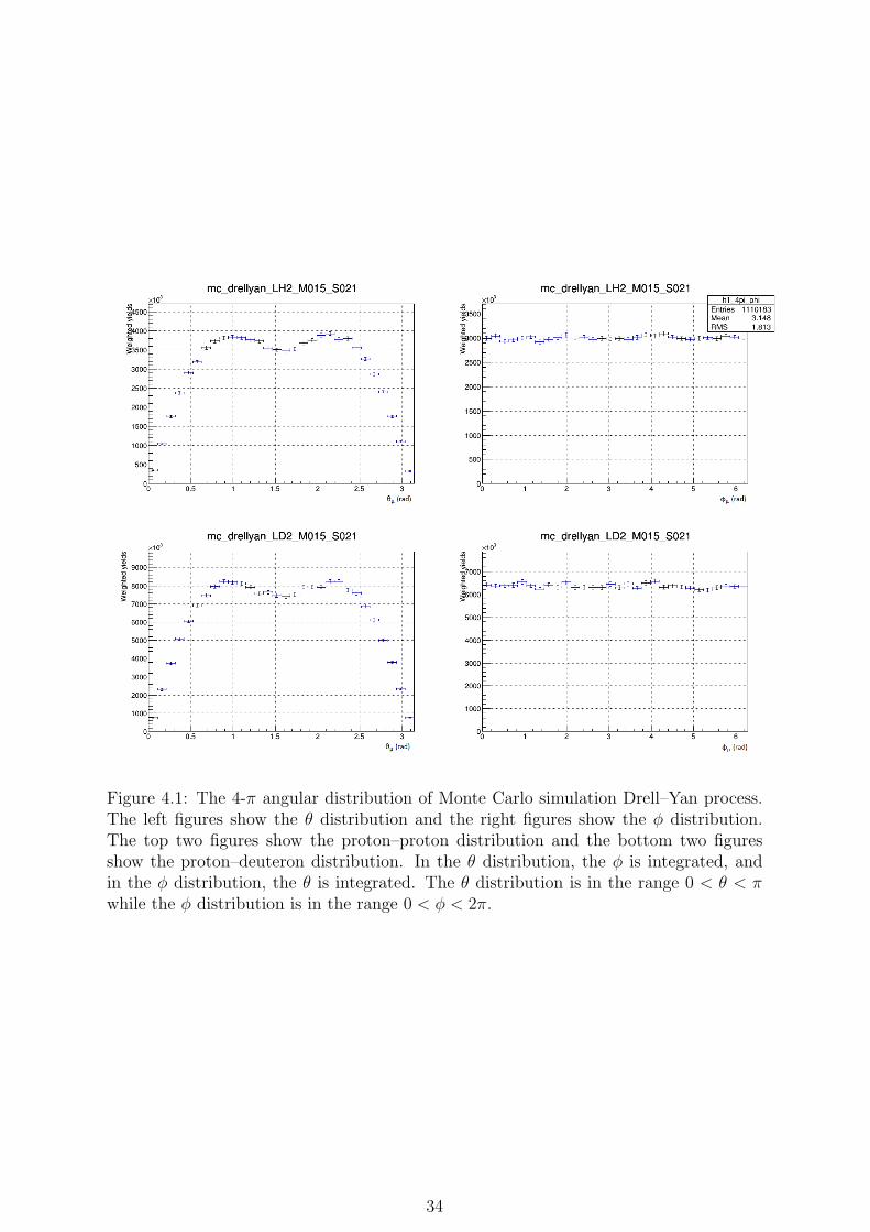
Figure 4.1: The 4-π angular distribution of Monte Carlo simulation Drell–Yan process.The left figures show the θ distribution and the right figures show the ϕ distribution.The top two figures show the proton–proton distribution and the bottom two figuresshow the proton–deuteron distribution. In the θ distribution, the ϕ is integrated, andin the ϕ distribution, the θ is integrated. The θ distribution is in the range 0 < θ < πwhile the ϕ distribution is in the range 0 < ϕ < 2π.
34

Figure 4.2: The two dimensional distribution of ϕ vs θ of Monte Carlo Drell–Yan processin 4π solid angle. The red color shows areas with higher yield.
higher closer to π/2 and is lower at θ = 0 and θ = π. There is a slight decrease near
θ ∼ π/2. The θ vs ϕ two dimensional plot shows the ϕ distribution is flat. The shapes
of the distributions are as expected, as explained next.
To check the validity of the Monte Carlo generated Drell–Yan angular distributions,
the distributions can be fitted with the angular distribution equation.
1
σ
dσ
dΩ=
[3
4π
1
λ+ 3
](1 + λcos2θ + µ sin 2θ cosϕ+
ν
2sin2θ cos2ϕ
)(4.1)
The generated Monte Carlo Drell–Yan angular distributions are calculated with zero
transverse momentum. In a Drell–Yan process with zero transverse momentum, the
values of the parameters are λ = 1, µ = 0, and ν = 0. In this case, the equation becomes
1
σ
dσ
dΩ=
3
16π
(1 + cos2θ
). (4.2)
It is important to note this differential cross section is expressed in the solid angle dΩ.
In Eq. 4.2, the distributions are expressed in only cosθ. Therefore it is convenient to
express Eq. 4.2 in dcosθ.
dΩ = sinθ dϕ dθ (4.3)
= d (cosθ) dϕ (4.4)
35

Substituting the dΩ and integrating over ϕ, Eq. 4.2 can be expressed as follows:
dσ
dcosθ=
3σ
8
(1 + cos2θ
)(4.5)
= A(1 + cos2θ
)(4.6)
The cosθ distribution is shown in Fig. 4.3. To check the validity of the angular dis-
Figure 4.3: The cos θ distribution of Monte Carlo Drell–Yan process. Dimuons in the 4πsolid angle are accepted.
tribution of the Monte Carlo Drell–Yan process, the cosθ distribution is fitted with the
following equation:dσ
dcosθ= A
(1 +B cos2θ
)(4.7)
where A and B are fitting paramters. The result of the fit is shown in Fig. 4.4.
The values of the fit are shown in table 4.1. Within errors, the parameter B = 1 as
Parameter Value
A 2.9× 10⁸ ± 1.6× 10⁶
B 0.99± 0.02
Table 4.1: The values of the fit A(1 + Bx2) for the Monte Carlo Drell–Yan cosθ distri-bution.
expected.
A method to check the validity of the both zenith and azimuthal distribution λ = 1,
µ = 0, ν = 0 is to fit the two-dimensional ϕ vs. θ distribution. Using equations 4.1 and
4.4, the ϕ and θ angular distribution of Drell–Yan process is expressed as follows:
dσ
dθ dϕ=
3
2
1
λ+ 3sinθ
(1 + λcos2θ + µ sin 2θ cosϕ+
ν
2sin2θ cos2ϕ
)(4.8)
36

Figure 4.4: The cosθ distribution of Monte Carlo Drell–Yan process fitted with thefunction A(1 + B cos2θ). The red line shows the fit function. Dimuons in the 4π solidangle are accepted.
Thus, the ϕ and θ angular distribution of Drell–Yan process is fitted with the following
function:dσ
dθ dϕ= A sinθ
(1 + λcos2θ + µ sin 2θ cosϕ+
ν
2sin2θ cos2ϕ
)(4.9)
Figure 4.5: The fit for the Monte Carlo Drell–Yan ϕ, θ angular distributions. The leftfigure shows the fit for the proton–proton Drell–Yan process angular distribution. Theright figure shows the fit for the proton–deuteron Drell–Yan process angular distribution.
The values of λ are close to 1 within errors, while the values of µ and ν are close to
zero within errors. These results are as expected and show the validity of the Drell–Yan
process angular distribution simulations for SeaQuest.
37

Parameter LH2 Target LD2 Target
A 6.4× 10⁶ ± 3.4× 10⁴ 1.9× 10⁷ ± 6.9× 10⁴
λ 0.96± 0.02 0.96± 0.02µ 9.4× 10⁻⁴ ± 7.8× 10⁻³ 1.6× 10⁻³ ± 7.9× 10⁻³
ν 0.013± 0.014 −0.023± 0.014χ2/ndf 983.4/896 1022/896
Table 4.2: The values of the fit for the Monte Carlo Drell–Yan ϕ, θ distribution.
4.1.2 In-Acceptance Angular Distribution
The SeaQuest Monte Carlo simulations simulate acceptance effects of the spectrometer
on dimuons angular distributions. Here, the angular distributions of Monte Carlo Drell–
Yan process measured by the SeaQuest spectrometer are presented.
There are two levels of acceptance effects applied by the SeaQuest spectrometer:
in-detector acceptance effects and tracking acceptance effects.
The in-detector acceptance effects are the effects of the geometry of the hodoscopes
and drift chambers on dimuon detection. A muon is in-detector when it passes through
all the hodoscopes and is detected by all drift chambers. Fig. 4.6 shows the definition
of in-detector. The black boxes represent the tracking station hodoscopes and drift
chambers.
Another acceptance effect is the tracking acceptace effects. Due to the tracking
algorithm and various tracking efficiencies, not all detected dimuons are tracked. This
results in acceptance effects in the tracking stage. The final in-acceptance dimuons used
for acceptance calculations are the tracked dimuons.
Figure 4.6: The definition of in-detector muon track. A muon is in-detector when themuon passes through all the drift chambers and all the hodoscopes. The black boxesrepresent tracking stations. The red line shows the out of acceptance muon track andthe blue line shows the in-detector muon track.
In-Detector Monte Carlo Angular Distribution
The in-detector angular distribution of the Drell–Yan process at SeaQuest is affected
by the geometry of the spectrometer. It is necessary to understand the effects of the
spectrometer acceptance on the angular distribution of Drell–Yan process. To understand
38

these effects, the Monte Carlo simulation data is used. Here, the in-detector Drell–Yan
angular distribution are presented. For these in-detector events, the dimuons pass all
hodoscopes and all drift chambers.
Another important condition for the study of angular distribution at SeaQuest is the
mass cut. As shown in section 3.3, dimuon events with mass > 4.2 GeV is studied at
SeaQuest. This mass cut is used to reduce the effects of background signals such as J/ψ
and ψ’ events, and the combinatorial background. Here, all the dimuon events are mass
> 4.2 GeV/c2.
Therefore, the Monte Carlo Drell–Yan events accepted at this stage follow these
conditions:
• Is detected by all hodoscopes
• Is detected by all drift chambers
• Mass > 4.2 GeV/c2
The in-detector angular distribution of the Drell–Yan events with the above con-
ditions are shown in Fig. 4.7. The left figures show the Monte Carlo Drell–Yan θ
distribution and the right figures show the ϕ distribution. The top two figures show
the proton–proton distribution and the bottom two figures show the proton–deuteron
distribution. In the θ distribution, the ϕ is integrated, and in the ϕ distribution, the θ is
integrated. The vertical axes (Weighted Yield) are shown in a log scale. The θ distribu-
tion is in the range 0 < θ < π while the ϕ distribution is in the range 0 < ϕ < 2π. The
dimuons considered here all passed through all the drift chambers and all the hodoscopes.
The characteristics of the θ and ϕ distributions are qualitatively as expected. The θ
distribution, which is µ+ angular distribution in the CS frame, is a single peak distribu-
tion. A larger θ angle indicates a larger opening angle of the dimuons. A dimuon with
a large opening angle will pass the outside of the spectrometer. Therefore, less dimuons
are accepted into the spectrometer. The ϕ distribution shows a modulation unlike the
4-π distribution which is flat. An explanation for this modulation is the geometry of the
SeaQuest spectrometer. The SeaQuest spectrometer is a square spectrometer. Therefore,
dimuons in the diagonal direction of the spectrometer would have a higher acceptance.
This is indicated in the ϕ distribution with two peaks.
Fig. 4.8 shows the two-dimensional angular distribution of the in-detector Monte Carlo
simulation Drell–Yan process. The shape of the distribution is a band.
39

Figure 4.7: The angular distributions of the in-detector Monte Carlo simulation Drell–Yan process. These distributions only include dimuons which passed through all ho-doscopes and all drift chambers. The left figures show the θ distribution and the rightfigures show the ϕ distribution. The top two figures show the proton–proton distributionand the bottom two figures show the proton–deuteron distribution. In the θ distribution,the ϕ is integrated, and in the ϕ distribution, the θ is integrated. The θ distribution isin the range 0 < θ < π while the ϕ distribution is in the range 0 < ϕ < 2π.
.
40

Figure 4.8: The ϕ vs θ distribution of in-detector Monte Carlo simulation Drell–Yan pro-cess. These distributions include only the in-detector dimuons. The left figure shows theproton–proton distribution and the right figure shows the proton–deuteron distribution.
Tracked Monte Carlo Angular Distribution
The second stage of the acceptance effects is the tracking acceptance effects. The detected
dimuons must always be tracked for analysis. Because only the tracked dimuons can be
analyzed in the real data, the effects of the tracking algorithm is always present in the
real data angular distributions. The SeaQuest tracking algorithm cannot reconstruct
every Monte Carlo Drell–Yan event. Therefore, the efficiency of the tracking algorithm
at SeaQuest creates a second acceptance effect. Thus, it is important to simulate and
understand the tracking effects before correcting the real data.
Here, the angular distribution of tracked Monte Carlo simulation Drell–Yan events are
presented. Fig. 4.9 shows the θ and ϕ distributions of tracked Monte Carlo simulation
Drell–Yan events. These distributions only include tracked dimuons. The left figures
show the θ distribution and the right figures show the ϕ distribution. The top two
figures show the proton–proton distribution and the bottom two figures show the proton–
deuteron distribution. In the θ distribution, the ϕ is integrated, and in the ϕ distribution,
the θ is integrated. The θ distribution is in the range π2−0.7 < θ < π
2+0.7. The basis of
this θ range is explained in section 5.1.2. This is to exclude bins with zero counts. The
ϕ distribution is in the range 0 < ϕ < 2π.
Fig. 4.10 shows the two-dimensional θ, ϕ distribution of the tracked Monte Carlo
Drell–Yan process. The left figure shows the proton–proton distribution while the right
figure shows the proton–deuteron distribution. The band shape is clearly visible. Com-
pared to the in-detector distribution in Fig. 4.8, the band shows a larger drop off at
wider θ ranges. A comparison of 4-π, in-detector, and tracked angular distributions is
presented in the next section.
41

Figure 4.9: The angular distributions of the tracked Monte Carlo simulation Drell–Yanprocess. These distributions only include tracked dimuons. The left figures show theθ distribution and the right figures show the ϕ distribution. The top two figures showthe proton–proton distribution and the bottom two figures show the proton–deuterondistribution. In the θ distribution, the ϕ is integrated, and in the ϕ distribution, theθ is integrated. The θ distribution is in the range π
2− 0.7 < θ < π
2+ 0.7 while the ϕ
distribution is in the range 0 < ϕ < 2π..
42

Figure 4.10: The ϕ vs θ distribution of tracked Monte Carlo simulation Drell–Yan process.These distributions are the tracked Drell–Yan dimuons. The right figure shows theproton–proton distribution and the left figure shows the proton–deuteron distribution.The θ distribution is in the range π
2− 0.7 < θ < π
2+ 0.7 while the ϕ distribution is in
the range 0 < ϕ < 2π
4.1.3 Comparison of 4-π and In-Acceptance Data
Here, the angular distribution of 4-π, and the two in-acceptance Monte Carlo are com-
pared. Fig. 4.11 shows the comparison between the three Monte Carlo distributions.
The black points show the 4-π distribution, the red points show the in-detector dis-
tribution, and the blue points show the tracked distribution. The data is compared in
the θ range π2−0.7 < θ < π
2+0.7 and ϕ range 0 < ϕ < 2π. The distribution for deuteron
target is about twice that of the distribution for proton target. This is due to the cross
section ratio. The Drell–Yan cross section for the proton–deuteron Drell–Yan process is
about twice that of the proton–proton Drell–Yan process. The acceptance effects of the
in-detector effects and tracking effects are visible.
43

Figure 4.11: The comparison of the three Monte Carlo distributions: 4-π, in-detector,and tracked distributions. The black points show the 4-π distribution, the red pointsshow the in-detector distribution, and the blue points show the tracked distribution. Theθ distribution is in the range π
2− 0.7 < θ < π
2+ 0.7 while the ϕ distribution is in the
range 0 < ϕ < 2π
44

The total yield of simulated Drell–Yan events for analysis is shown in Table 4.3.
4-π In-detector Tracked
LH2 8.70457 ×10⁸ 2.76918 ×10⁷ 1.20218 ×10⁷
LD2 1.83991 ×10⁸ 7.07614 ×10⁷ 3.07497 ×10⁷
Table 4.3: The number of Drell–Yan dimuon events in each distribution.
It is important to note that the number of thrown events is different for the 4-π and in-
acceptance distributions. The thrown events is the total number of generated simulation
events. This is regardless of the reaction type and detection. The 4-π simulation has less
events thrown. The number of events thrown for each simulation data is shown in table
4.4. Therefore, there are 35000000/2000000 = 17.5 times less events thrown for the 4-π
4-π In-detector Tracked
2000000 35000000 35000000
Table 4.4: The number of thrown events in each distribution.
distribution.
Corrected for the ratio of thrown events, it is possible to estimate the total acceptance
effects of the in-detector effect and tracking effect by calculcating
acceptance =in-acceptance
4-π(4.10)
for both in-detector and tracked distributions. The results are shown in table 4.5.
In-detector Tracked
LH2 0.0318 0.0138LD2 0.0385 0.0167
Table 4.5: The acceptance effect of in-detector and tracked distributions.
The total acceptance effect of the spectrometer geometry is around 3% to 4% of all
Drell–Yan dimuon events. The total acceptance effect of the tracking at SeaQuest is
around 1.5% of all Drell–Yan dimuon events.
Fig. 4.12 shows the comparison between in-detector distributions and tracked distri-
butions.
The effect of the tracking not only has an effect on the absolute number of events,
but also on the shape of the distribution. A comparison of the shapes of the distributions
for proton–proton Drell–Yan process are shown in Fig. 4.14. The two distributions are
normalized with integrated yields.
Dividing the tracked distribution with the in-detector distribution yields the ratio of
the two distributions.
45

Figure 4.12: The comparison of the two in-acceptance distributions of Monte Carlo sim-ulation Drell–Yan process. The red points show the in-detector distribution, while theblue points show the tracked distribution. The top figures show the proton–proton distri-bution and the bottom figures show the proton–deuteron distribution. The θ distributionis in the range π
2− 0.7 < θ < π
2+0.7 while the ϕ distribution is in the range 0 < ϕ < 2π
46

Figure 4.13: Comparison of the two in-acceptance Monte Carlo simulation distributionsnormalized with integrated yield. The red points show the in-detector distribution whilethe blue points show the tracked distribution. The left figure shows the θ distributionwhile the right figure shows the ϕ distribution. The top two figures show the proton–proton Drell–Yan distributions and the bottom two figures show the proton–deuteronDrell–Yan distributions.
47

Figure 4.14: The distribution of Monte Carlo tracked distribution / in-detector distri-bution. The left figure shows the quotient distribution of θ while the right figure showsthe quotient distribution of ϕ. The top two figures show the proton–proton Drell–Yandistributions and the bottom two figures show the proton–deuteron Drell–Yan distribu-tions.
48

The left figure shows the quotient distribution of θ while the right figure shows the
quotient distribution of ϕ. Compared to the in-detector distribution, the tracked distri-
bution has a narrower θ distribution. The divided distribution drops to near 0.25 at the
edges of the θ range for proton–proton distribution and near 0.17 for proton–deuteron
distribution. The tracking algorithm has a narrower θacceptance than the detectors.
The difference in the ϕ distribution is less prominent than the difference in θ distri-
bution. This indicates that the in-detector ϕ distribution and the tracked ϕ distribution
are similar.
The tracked ϕ distributions are near flat after all acceptance effects are considered. As
a result, the azimuthal angular distribution at SeaQuest requires only a slight acceptance
correction.
49

4.2 Real Data Angular Distributions
Here, the angular distributions of the real data are presented. All real data dimuons are
mass > 4.2 GeV.
4.2.1 Raw Angular Distribution
First the angular distributions of the raw data obtained at SeaQuest is presented. The
θ distribution uses the fiducal θ cut and is in the range π2− 0.7 < θ < π
2+ 0.7 while
the ϕ distribution is in the range 0 < ϕ < 2π. The two dimensional θ vs ϕ distribution
Figure 4.15: The real data angular distribution of dimuon events. The left figures showthe θ distribution and the right figures show the ϕ distribution. The top two figures showthe proton–proton distribution and the bottom two figures show the proton–deuterondistribution. In the θ distribution, the ϕ is integrated, and in the ϕ distribution, theθ is integrated. The θ distribution is in the range π
2− 0.7 < θ < π
2+ 0.7 while the ϕ
distribution is in the range 0 < ϕ < 2π.
is shown in Fig. 4.16. The left figure shows the angular distribution for proton–proton
events while the right figure shows the angular distribution for proton–deuteron events.
The θ distribution is similar to the tracked simulation distribution. The θ distribution
does not drop off at the edges compared to the simulation data, and this is likely the
result of background signals. The ϕ distribution shows a significant modulation. The
50

Figure 4.16: The two dimensional angular distribution of real data dimuon events. Theleft figure shows the angular distribution for proton–proton events while the right figureshows the angular distribution for proton–deuteron events. There is a significant ϕmodulation.
simulation data indicated a near-flat ϕ distribution. This azimuthal ϕ distribution needs
attention.
51

4.2.2 Beam Angle Correction
A reason for the significant azimuthal modulation in the real data can be a beam angle
bias. If the beam has a particular angle relative to the z axis, the momenta of the muons
will have a bias in a particular direction. Here, a study and a correction on the beam
angle bias is presented.
To study the existence of bias effects of the beam angle, the slopes of the dimuon
momenta are studied. The slopes of the dimuon momenta can be expressed as
αx =dpx
dpz
(4.11)
αy =dpy
dpz
(4.12)
where αx and αy are the beam slopes and dpx, dpy, and dpz are the dimuon momenta
in lab frame x, y, z direction respectively. The schematics of the dimuon slope is shown
in Fig. 4.17.
Figure 4.17: The definition of dimuon momenta slope α.
If the beam is statistically parallel to the y axis, the distribution of the slopes should
be centered around 0. If the beam has a significant slope relative to the z axis, the dis-
tributions should be centered around a non-zero value. Fig. 4.18 shows the distribution
of the slopes of the dimuon momenta.
The top two figures show the dimuon momenta slope distributions for proton–proton
events and the bottom two figures show the dimuon momenta slope distributions for
proton–deuteron events. The left two figures show the dpx/dpz distribution and the
right two figures show the dpy/dpz distribution.
The dpx/dpz distribution seems to be centered around zero. This indicates no signif-
icant slopes in the x direction. The dpy/dpz distribution shows a shift to the postive y
direction. This indicates a positive y direction beam angle bias.
To estimate the beam angle, the dpy/dpz distribution is fitted with a simple Gaussian
distribution,
f(x) = A exp
(−(x−B)2
2C
)(4.13)
for the top half of the distribution. Only the top half of the function is fitted to reduce
52

Figure 4.18: The dimuon momenta slopes. The top two figures show the dimuon mo-menta slope distributions for proton–proton events and the bottom two figures show thedimuon momenta slope distributions for proton–deuteron events. The left two figuresshow the dpx/dpz distribution and the right two figures show the dpy/dpz distribution.
53

the effects of background events. The value of the parameter B shows the center of the
distribution and indicates the value of the beam slope.
The results of the fit are shown in Fig. 4.19. The left figure shows the fit results
Figure 4.19: The results of the Gaussian fit for y direction dimuon momenta slopedistribution. The left figure shows the fit results for the proton–proton dimuon events,and the right figure shows the fit results for the proton–deuteron dimuon events. Theblack solid line is the Gaussian function fitted for the top half of the distribution.
for the proton–proton dimuon events, and the right figure shows the fit results for the
proton–deuteron dimuon events. The results of the fit are shown in Table 4.6.
Proton Target Deuteron Target
A 250.1 ± 8.2 275.3 ± 8.9B 0.0042 ± 0.0003 0.0038 ± 0.0003C 0.0083 ± 0.0004 0.0083 ± 0.0004
Table 4.6: The fit results of Gaussian fit for y direction dimuon momenta slope distribu-tion.
The results show a significant positive y-direction slope for the beam angle. Using
the values obtained from the fit, it is possible to correct the data for the beam angle.
The data is corrected with the functions shown in Table 4.7.
The real data angular distributions can now be corrected using the equations in Table
4.7. The results of the beam angle corrected angular distributions are shown in Fig. 4.20.
The left figures show the θ distribution and the right figures show the ϕ distribution.
The top two figures show the proton–proton distribution and the bottom two figures
show the proton–deuteron distribution. In the θ distribution, the ϕ is integrated, and
in the ϕ distribution, the θ is integrated. The θ distribution is in the range 0 < θ < π
while the ϕ distribution is in the range 0 < ϕ < 2π.
The significant azimuthal ϕ modulation disappears and the ϕ distribution becomes
flatter. There is less change for the shape of the θ distribution.
54

Target Equation
Proton dp′y = dpy − 0.0042× dpzDeuteron dp′y = dpy − 0.0038× dpz
Table 4.7: The beam angle correction equations for each target. dp′y is the correcteddimuon y-momentum, dpy is the raw dimuon y-momentum, and dpz is the dimuon z-momentum.
Figure 4.20: The real data angular distributions corrected for the beam angle bias. Theleft figures show the θ distribution and the right figures show the ϕ distribution. Thetop two figures show the proton–proton distribution and the bottom two figures showthe proton–deuteron distribution. In the θ distribution, the ϕ is integrated, and in theϕ distribution, the θ is integrated. The θ distribution is in the range 0 < θ < π whilethe ϕ distribution is in the range 0 < ϕ < 2π.
55

Fig. 4.21 shows the corrected two-dimensional angular distribution of the real data
at SeaQuest.
Figure 4.21: The beam angle corrected, real data ϕ vs θ two-dimensional angular distri-bution. The θ distribution is in the range π
2− 0.7 < θ < π
2+0.7 while the ϕ distribution
is in the range 0 < ϕ < 2π
The final distribution includes a total of about 30000 dimuons, including a signifi-
cant amount of background events. A simple cut for background events using chamber
intensity will be shown in section 5.1.2.
56

Chapter 5
Acceptance Correction and
Extraction of Angular Distribution
Parameters
5.1 Acceptance Correction
The correction for acceptance effects will be applied by dividing the real data angular
distribution with the acceptance distribution.
The process for acceptance correction is as follows:
1. Test a simple acceptance correction using Monte Carlo simulation data
2. Compare the simulation data and real data
3. Calculate the acceptance distribution using Monte Carlo data
4. Divide the real data θ, ϕ two dimensional angular distribution with the two-
dimensional θ, ϕ acceptance distribution.
The acceptance is calculated as follows:
Acceptance =Tracked Monte Carlo Distribution
4π Monte Carlo Distribution(5.1)
After the acceptance is calculated, the real data angular distribution will be divided by
the acceptance bin-by-bin to obtain the final acceptance-corrected angular distribution.
5.1.1 Acceptance Correction Using Monte Carlo Data
Before an attempt at an acceptance correction of the real data, a simple test of the
acceptance correction is performed by correcting the Monte Carlo simulation data. By
checking the Monte Carlo simulation data, a need for a fiducial θ cut was found.
The acceptance correction in the present thesis is a bin-by-bin division by acceptance.
The acceptance must have non-zero value or the real data in the bin will be lost. As
shown in Fig. 4.8, some bins in the θ, ϕ two dimensional distribution of in-acceptance
57

have no data. Bins with θ value further away from π2are zero. It is necessary to omit
these bins for acceptance corrections. To find a suitable range for such a θ cut, an
acceptance correction on the Monte Carlo data is performed.
Dividing the in-acceptance data by the acceptance should yield a 4-π distribution
back. Monte Carlo simulation data is used to test this. An acceptance using in-
acceptance Monte Carlo simulation data is calculated as:
Acceptance =In-Detector Monte Carlo Distribution (not tracked)
4π Monte Carlo Distribution(5.2)
The acceptance distributions calculated using Eq. 5.2 is shown in Fig. 5.1. The left figure
Figure 5.1: The acceptance calculated by in-detector / 4-π Monte Carlo data. The leftfigure shows the proton–proton distribution while the right figure shows the proton–deuteron distribution. The θ distribution is in the range 0 < θ < π while the ϕ distribu-tion is in the range 0 < ϕ < 2π.
shows the proton–proton distribution while the right figure shows the proton–deuteron
distribution. The θ distribution is in the range 0 < θ < π while the ϕ distribution is in
the range 0 < ϕ < 2π. There are some bins in the acceptance distribution with value
0 because some bins in the in-detector data have value 0. The θ and ϕ projections are
shown in Fig. 5.2. The left figures show the θ distribution and the right figures show
the ϕ distribution. The ϕ is integrated for the θ distribution and vice versa.
The in-detector distribution (Fig. 4.8) is divided by the acceptance calculated in Fig.
5.1. This is the acceptance correction.
4π Distribution =In-Detector Monte Carlo Distribution (not tracked)
Acceptance(5.3)
=In-Detector Monte Carlo Distribution
In-Detector Monte Carlo Distribution× 4π Distribution (5.4)
Dividing the in-detector distribution with the acceptance should recreate the 4-π
distributions. Fig. 5.3 shows the results of the acceptance corrected in-detector distri-
butions and the 4-π distributions. The red data points show the corrected in-detector
distributions while the blue points show the 4-π distributions. The top two figures show
58

Figure 5.2: The θ and ϕ projections of the acceptance distribution in Fig. 5.1. Theleft figures show the θ distribution and the right figures show the ϕ distribution. The θdistribution is in the range 0 < θ < π while the ϕ distribution is in the range 0 < ϕ < 2π.
59

Figure 5.3: Comparison of the acceptance corrected in-detector Monte Carlo distributionand 4-π Monte Carlo distribution. The red data points show the corrected in-detectordistributions while the blue points show the 4-π distributions. The left figures show theθ distribution and the right figures show the ϕ distribution. he θ distribution is in therange 0 < θ < π while the ϕ distribution is in the range 0 < ϕ < 2π.
60

the proton–proton distributions and the bottom two figures show the proton–deuteron
distributions. The left figures show the θ distribution and the right figures show the ϕ
distribution. The θ distribution is in the range 0 < θ < π while the ϕ distribution is in
the range 0 < ϕ < 2π. The ϕ is integrated for the θ distribution and vice versa.
The corrected in-detector distributions do not recreate the 4-π distributions. The
values of ϕ for the corrected in-detector distributions are constantly lower than the values
for the 4-π distributions as shown in Fig. 5.3. The values of the θ for the corrected in-
detector distribution is lower outside of the range π2− 0.7 < θ < π
2+ 0.7, as shown in
Fig. 5.3.
Figure 5.4: Comparison of the corrected in-detector θ distribution and the 4-π θ distri-bution. The range inside the red lines matches well, but the corrected distribution islower than the 4π distribution in the range outside the red lines.
The data points inside the red lines in Fig. 5.4 match well. However, there is a
significant difference outside of the red lines.
This is due to the data bins with value 0 in the in-detector angular distributions.
These bins cannot be corrected to recreate the 4-π distribution with a bin-by-bin accep-
tance division. Therefore, these bins will be ommited from the correction. These value
0 bins are cut from the data by using only the data inside the red lines in Fig. 5.4. The
θ range π2− 0.7 < θ < π
2+ 0.7. This is the fiducial θ cut.
The acceptance distribution defined in Eq. 5.2 with the fiducial cut is shown in Fig.
5.5.
There are no bins with value 0 in Fig. 5.5. This should fix the correction problem.
Fig. 5.6 shows the comparison between the acceptance corrected in-detector distri-
butions and the 4-π distributions with the fiducial θ cut.
The red points show the corrected in-detector distribution and the blue points show
the 4-π distribution. The top figures show the proton–proton distributions and the
bottom figures show the proton–deuteron distributions. The left figures show the θ
distribution and the right figures show the ϕ distribution.
The corrected in-detector distribution and the 4-π distribution matches well.
61

Figure 5.5: The Monte Carlo in-detector / 4-π acceptance distribution with the fiducialθ cut. The θ distribution is in the range π
2− 0.7 < θ < π
2+ 0.7 while the ϕ distribution
is in the range 0 < ϕ < 2π. The left figure is the proton–proton acceptance distributionand the right figure is the proton–deuteron acceptance distribution.
62

Figure 5.6: Comparison between the corrected Monte Carlo in-detector distributionand the 4-π Monte Carlo distribution with the fiducial θ cut. The red points show thecorrected in-detector distribution and the blue points show the 4-π distribution. The topfigures show the proton–proton distributions and the bottom figures show the proton–deuteron distributions. The left figures show the θ distribution and the right figures showthe ϕ distribution. he θ distribution is in the range 0 < θ < π while the ϕ distributionis in the range 0 < ϕ < 2π.
63

5.1.2 Comparison of Simulation and Real Data
Another step in ensuring the effectiveness of the acceptance correction is comparing
the tracked Monte Carlo data and the real data. A large discrepancy between the
tracke Monte Carlo data and the real data could indicate that the simulation does not
sufficiently reproduce the real data. To check for any discrepancies, the comparison
between simulation data and real data is performed. By comparing the tracked Monte
Carlo data and the real data, a need to consider the beam intensity was found.
Here, the real data is divided into four bins of beam intensity. The beam intensity is
the chamber intensity defined in section 3.1. This definition of the beam intensity consid-
ers the drift chamber drift times. This chamber intensity is calculated as the weighted av-
erage of the ±13 RF buckets in proximity to the incident RF bucket. The beam intensity
typically is proportional to the number of hits detected in the drift chambers and is pro-
portional to the number of fake muon tracks. Thus, studying the beam intensity gives im-
portant information on the properties of the accidental dimuon background signals. The
beam intensity is studied in the intensity range 0 < intensity < 60, 000. In the present
thesis, this intensity is divided into four equal intensity ranges of 0 < intensity < 15000,
15000 < intensity < 30000, 30000 < intensity < 45000, and 45000 < intensity < 60000.
The Monte Carlo data does not have any simulated background signals. Therefore,
a large discrepancy between the tracked Monte Carlo data and real data can be due to
the accidental dimuon background.
Fig. 5.7 shows the comparison between the tracked Monte Carlo distributions and
the real data in four beam intensity bins. Here, the real data has already been corrected
for beam angle. To emphasize the difference in the shapes of the distributions, the
Monte Carlo data is normalized by the integral of the real data. The comparison of the
θ distributions show a increasing discrepancy at the edges of the θ range.
To evaluate the discrepancies at each beam intensity bin, the real data distribution
is divided by the tracked Monte Carlo distribution. Because the tracked Monte Carlo
distributions are normalized with the integral of the real data, the ratio should equal 1
if the distributions match in shape. Fig. 5.8 shows the ratio distribution of real data
divided by the tracked Monte Carlo data.
The edges of the θ distributions rise with higher beam intensity. At the lowest
intensity, most points are around 1. At the edges of the distribution, there is around 1
to 2 times more real data at 0.9 rad, and 2 to 3 times more at 2.2 rad. At the highest
beam intensity, the real data and tracked Monte Carlo distributions match in the range
1.2 rad < θ < 2.1 rad. There is around 3 to 5 times more real data than the tracked
Monte Carlo distribution at 0.9 rad and around 2 to 4 times more at 2.2 rad.
A previous study on the simulated SeaQuest mix dimuon background [4] showed that
the mix dimuon background θ distribution has two peaks around 1 and 2.2 rad. Fig. 5.9
shows the mix dimuon background simulation θ distribution.
The increasing discrepancy at 1 rad and 2.2 rad at higher intensities agrees with
the mix dimuon background distribution shape. Therefore, the discrepancy between
the real data and the tracked Monte Carlo data is likely due to the accidental dimuon
background.
64

Figure 5.7: The comparison of θ between tracked Monte Carlo data and the real data.The real data distributions are divided into four bins of beam intensity. The black pointsshow the Monte Carlo distribution while the red points show the real data distribution.The yields are normalized with integral. The simulation and real data match well at lowbeam intensities.
65

Figure 5.8: The ratio of real data / Monte Carlo data for θ. The real data distributionsare divided into four bins of beam intensity. The simulation and real data match well atlow beam intensities.
66

Figure 5.9: The θ distribution of the mix dimuon background at SeaQuest [4]. Theθ peak is around 1 and 2.2. The left figure shows the proton–proton mix backgrounddistribution and the right figure shows the proton–deuteron mix background distribution.
The comparison of ϕ distributions is presented next. Fig. 5.10 shows the ϕ com-
parison between the tracked Monte Carlo distributions and the real data in four beam
intensity bins. The same beam intensity bins are used. To emphasize the difference in
the shapes of the distributions, the Monte Carlo data is normalized by the integral of
the real data.
The black points show the tracked Monte Carlo distribution while the red points
show the real data distribution. There is a larger modulation in the ϕ distributions at
higher intensities.
To evaluate the discrepancy, the real data is divided by the tracked Monte Carlo
distribution. The ratio distribution of the real data to tracked Monte Carlo distribution
is shown in Fig. 5.11. Similar to the θ distributions, the real data and tracked Monte
Carlo distributions match well at lower intensities. Almost all points are around 1 at
the lowest intensity range. However, a modulation appears with higher intensities. The
ratio modulates around 0.5 to 1.5 at the highest intensity range.
A previous study found the ϕ mix dimuon background distribution. The ϕ mix
dimuon background distribution is shown in Fig. 5.12. The shape agrees well with
the shape of the real data / tracked Monte Carlo ratio distribution at high intensity.
Therefore, the discrepancy between the real data and tracked Monte Carlo data ϕ is
again likely to be due to the accidental dimuon background signals.
In the present thesis, only the real data with beam intensity in the lowest intensity
range will be used to extract the angular distribution parameters. This will reduce the
effects of fake dimuon signals. Fig. 5.13 shows the results of a previous study [7] on the
ratio of mix background signals to Drell–Yan events.
In the intensity range 0 < intensity < 15000, the mix background ratio is around
67

Figure 5.10: The comparison of ϕ between tracked Monte Carlo data and the real data.The real data distributions are divided into four bins of beam intensity. The black pointsshow the Monte Carlo distribution while the red points show the real data distribution.The simulation and real data match well at low beam intensities.
68

Figure 5.11: The comparison of ϕ between tracked Monte Carlo data and the real data.The real data distributions are divided into four bins of beam intensity. The simulationand real data match well at low beam intensities.
69

Figure 5.12: The ϕ distribution of the mix dimuon background at SeaQuest [4]. The leftfigure shows the proton–proton mix background distribution and the right figure showsthe proton–deuteron mix background distribution.
Figure 5.13: The ratio of mix background to Drell–Yan events vs chamber intensity.The left figure shows the background ratio for LH2 target and the right figure showsthe background ratio for LD2 target. The background ratio is around 5 to 10% for theintensity range 0 < intensity < 15000 [7].
70

5%. By cutting the chamber intensity at 15000, only about 5 to 10% of the data is
background.
71

5.1.3 Acceptance Correction
The conditions for the acceptance correction are summarized.
To summarize the conditions for the real data, only the real data dimuon events with
the following conditions are used for the angular distribution extraction:
• mass > 4.2 GeV/c2
• beam angle corrected using Table 4.6
• π2− 0.7 < θ < π
2+ 0.7
• 0 < beam intensity < 15000
The number of dimuon events left with these conditions is shown in Table 5.1.
Target Proton Target Deuteron Target
Number of dimuons 2037 2295
Table 5.1: The number of final dimuon events used for acceptance correction.
Fig. 5.14 shows the real data angular distributions used for the acceptance correction.
Figure 5.14: The real data angular distribution after the various cuts used for acceptancecorrection. The θ distribution is in the range π
2−0.7 < θ < π
2+0.7 while the ϕ distribution
is in the range 0 < ϕ < 2π.
On the other hand, the acceptance is calculated using the tracked Monte Carlo dis-
tribution dimuons with the following conditions:
• Mass > 4.2 GeV/c2
• π2− 0.7 < θ < π
2+ 0.7
• Passes all hodoscopes and all drift chambers
72

• Successfully tracked
The acceptance is calculated by dividing the tracked Monte Carlo distribution with
conditions above with the 4-π Monte Carlo distribution. Fig. 5.15 shows the calculated
acceptance.
Figure 5.15: The acceptance calculated by dividing the tracked Monte Carlo data withthe 4-π Monte Carlo data. The θ distribution is in the range π
2− 0.7 < θ < π
2+0.7 while
the ϕ distribution is in the range 0 < ϕ < 2π.
5.1.4 Corrected Angular Distributions
The corrected angular distributions of the real data are obtained by dividing the real
data with the acceptance. The results are shown in Fig. 5.16.
Figure 5.16: The acceptance corrected real data angular distributions. The θ distributionis in the range π
2− 0.7 < θ < π
2+0.7 while the ϕ distribution is in the range 0 < ϕ < 2π.
The z (color) axis is shown in log scale. There are several bins with large values due
to the low acceptance values. The θ and ϕ projections are shown in Fig. 5.17. There are
several bins with extremely high value. These bins have large errors and will not affect
the fit as much as bins with small errors.
73

Figure 5.17: The θ and ϕ projections of the acceptance corrected real data angulardistributions. The vertical axis (corrected yield) is log scale. The left figures show theθ distribution and the right figures show the ϕ distribution. The top two figures showthe proton–proton distribution and the bottom two figures show the proton–deuterondistribution. In the θ distribution, the ϕ is integrated, and in the ϕ distribution, theθ is integrated. The θ distribution is in the range π
2− 0.7 < θ < π
2+ 0.7 while the ϕ
distribution is in the range 0 < ϕ < 2π.
74

5.2 Extraction of Angular Distribution
5.2.1 Angular Distribution Fit
The real data distribution is fitted with the angular distribution function,
dσ
dϕdθ= A sinθ
(1 + λ cos2θ + µ sin 2θ cosϕ+
ν
2sin2θ cos2ϕ
)(5.5)
The result of the fit is shown in Fig. 5.18.
Figure 5.18: The fitted angular distributions of real data. The left figure shows the fitresult for the proton–proton distribution and the right figure shows the result for theproton–deuteron distribution. The θ distribution is in the range π
2− 0.7 < θ < π
2+ 0.7
while the ϕ distribution is in the range 0 < ϕ < 2π.
The left figure shows the fit result for the proton–proton distribution and the right
figure shows the result for the proton–deuteron distribution. The extracted values are
shown in the next section.
To check the fit using one-dimensional θ and ϕ distributions, Eq. 5.5 must be inte-
grated for each variable.
Integrating Eq. 5.5 over ϕ yields the θ distribution,
dσ
dθ= A′ sinθ
(1 + λ cos2θ
). (5.6)
The one-dimensional θ distribution is fitted with Eq. 5.6. Fig. 5.19 shows the results
of the fit for the θ distribution. The extracted values of the fit are shown in Table 5.2.
The negative values of λ indicate the lower yield in the θ distribution near the edges of
the θ range, θ = π2− 0.7 and θ = π
2− 0.7. A (1 + cos2 θ) distribution is highest at θ = 0
and θ = π, while lowest at θ = π2
Next, the one-dimensional ϕ distribution is presented. Integrating Eq. 5.5 over θ
75

Figure 5.19: The fitted θ distributions of real data. The ϕ is integrated. The left figureshows the fit result for the proton–proton distribution and the right figure shows theresult for the proton–deuteron distribution. The θ distribution is in the range π
2− 0.7 <
θ < π2+ 0.7.
Parameter LH2 Target LD2 Target
A′ 5012± 144 4705± 129λ −2.0± 0.2 −2.0± 0.2χ2/ndf 39.84/28 42.36/28
Table 5.2: The values of the fit for the acceptance corrected real data θ distribution.
76

yields the ϕ distribution,
dσ
dϕ= A′′ (3 + λ+ ν cos22ϕ
). (5.7)
The ϕ distribution is fitted with Eq. 5.7. Fig. 5.20 shows the results of the fit for
the ϕ distribution.
Figure 5.20: The fitted ϕ distributions of real data. The ϕ is integrated. The left figureshows the fit result for the proton–proton distribution and the right figure shows theresult for the proton–deuteron distribution. The ϕ distribution is in the range 0 < ϕ <2π.
The extracted values of the parameters are shown in Table 5.3. The bins with large
Parameter LH2 Target LD2 Target
A′′ 1.4× 10³ ± 720 1.3× 10³ ± 660λ −0.48± 1.3 −0.52± 1.2ν 0.42± 0.28 0.48± 0.28χ2/ndf 46.54/27 31.66/27
Table 5.3: The values of the fit for the acceptance corrected real data ϕ distribution.
values do not seem to largely affect the fit result in the fit. This is likely due to the large
errors for the bins with large value.
77

5.2.2 Parameter Values
The final parameter values are extracted from the ϕ vs. θ two-dimensional fit. The
parameter values of the fit in Fig. 5.18 are shown in Table 5.4.
Parameter LH2 Target LD2 Target
A 122.3± 4.448 117.7± 4.008λ 1.012± 0.7385 0.3174± 0.6694µ −0.06792± 0.1638 −0.1417± 0.1492ν −0.01703± 0.09037 −0.0734± 0.08368χ2/ndf 485.1/543 497.7/560
Table 5.4: The values of the fit for the acceptance corrected real data Drell–Yan ϕ, θdistribution.
These values are close to the parameter set of λ = 1, µ = 0, and ν = 0 within errors.
However, non-zero parameter values are not excluded at the present statistical errors.
The order of the azimuthal distribution parameter ν agrees with the results of previous
experiments within errors. In previous proton–proton and proton–deuteron experiments
studying the azimuthal parameter ν, the value was extracted to be in the order of 0.01
to 0.1. The results in the present thesis agree with these results.
78

Chapter 6
Conclusions and Discussions
6.1 Angular Distribution Parameters
In the present thesis, angular distribution parameters of the Drell–Yan process was ex-
tracted using real data at SeaQuest. The values are compared with the values extracted
by the previous Fermilab experiment E866. In the present thesis, the parameters were
extracted over all values of transverse momentum pT . Therefore, the data points are
plotted on the average value of pT for each target. The average value of pT for each
target is shown in Table 6.1.
Target Proton Target Deuteron Target
Average pT (GeV/c) 0.90 0.85
Table 6.1: The average value of transverse momentum pT for each target
For Fig. 6.1, 6.2, and 6.3, the solid black points show the parameter values for proton–
proton reactions in E866, the open points show the parameter values for proton–deuteron
reactions in E866, the red points show the parameter values for proton–proton reactions
in the present thesis, and the blue points show the parameter values for proton–deuteron
reactions in the present thesis.
Within statistical errors, the values extracted in the present thesis agree with the
values extracted by E866.
79

Figure 6.1: The value of λ extracted in the present thesis compared to the values ex-tracted by the previous Fermilab experiment E866. The red point shows the proton–proton parameter and the blue point shows the proton–deuteron parameter extracted inthe present thesis.
Figure 6.2: The value of µ extracted in the present thesis compared to the values ex-tracted by the previous Fermilab experiment E866. The red point shows the proton–proton parameter and the blue point shows the proton–deuteron parameter extracted inthe present thesis.
80

Figure 6.3: The value of ν extracted in the present thesis compared to the values ex-tracted by the previous Fermilab experiment E866. The red point shows the proton–proton parameter and the blue point shows the proton–deuteron parameter extracted inthe present thesis.
6.2 Future Improvements
1. Statistical Error
The statistical error is a major source of error in the present thesis. The data used
in the present thesis consisted of only one data set taken at SeaQuest during Run
3. The data set used in the present thesis is data set 67-1. Table 6.2 shows the
protons on target (POT) measured at SeaQuest for each data set taken during Run
3. The data used in the present thesis consists of around 45% of the data available
for LH2 target and around 50% of the data available for LD2 target taken during
Run 3.
Run 3 Data Set POT for LH2 Target % of total POT for LD2 Target % of total
67-1 5.0714× 10¹⁶ 44.7% 2.9722× 10¹⁶ 50.5%67-2 5.6573× 10¹⁶ 49.9% 2.6096× 10¹⁶ 44.3 %70 6.0457× 10¹⁵ 5.3 % 3.0211× 10¹⁵ 5.1%Total 1.133327× 10¹⁷ - 5.8852× 10¹⁶ -
Table 6.2: The protons on target measured at SeaQuest for each data set.
Data taking at SeaQuest is ongoing and more data will be available in the future.
2. Background Subtraction
In the present thesis, the background signals were removed from the real data
by choosing a low beam intensity range. The beam intensity used in the present
81

thesis is the chamber intensity defined in section 3.1. In the present thesis, the
beam intensity was cut at 15000 to reduce background signals.
This results in a reduction of statistics. Fig. 6.4 shows the beam intensity (chamber
intensity) distribution in the data set 67-1.
Figure 6.4: The chamber intensity distribution for data set 67-1. The events with beamintensity from 0 to 15000 were used in the analysis in the present thesis. Around 26%of all events are in the range 0 < intensity < 15000
About 26% of all events are in the beam intensity range 0 < intensity < 15000.
To maintain more dimuon events, an efficient subtraction of background events
can be useful. This will require an analysis on the angular distributions of mix
background events and an analysis on the ratio of background events to real Drell–
Yan dimuon events.
82

Chapter 7
Summary
In Summary,
• The present research measured the azimuthal angular distribution of Drell–Yan
process at SeaQuest.
• The purpose of SeaQuest is to study the internal structure of the nucleon.
• Transverse-momentum-dependent parton distribution functions (TMD PDF) show
the three-dimensional structure of the nucleon.
• The angular distribution of Drell–Yan process is expressed as:
dσ
dΩ∝ 1 + λ cos2θ + µ sin 2θ cosϕ+
ν
2sin2θ cos2ϕ (7.1)
• A TMD PDF known as the Boer–Mulders function causes an azimuthal modula-
tion.
• Data taken in 2015 was used to measure the angular distribution of the Drell–Yan
process.
• The validity of the 4-π angular distribution of the Monte Carlo simulation data at
SeaQuest was confirmed.
• The angular distribution of tracked Monte Carlo simulation data was measured.
Around 1% of all dimuons generated in the simulation are successfully tracked.
• A positive y-direction beam angle was found and was corrected for the real data.
• By comparing the Monte Carlo data and the real data, the beam intensity depen-
dence of the real data was found.
• The acceptance at SeaQuest was calculated by dividing the tracked Monte Carlo
data with the 4-π Monte Carlo data.
83

• After the real data is corrected by acceptance, the angular distribution parameters
were found: λ = 1.0 ± 0.74, µ = −0.068 ± 0.16, ν = −0.017 ± 0.090 for proton–
proton Drell–Yan process and λ = 0.32±0.67, µ = −0.14±0.15, ν = −0.073±0.084
for proton–deuterium Drell–Yan process.
This thesis showed the analysis of angular distribution of Drell–Yan process. With
reduced statistical and systematic errors in future, we can investigate the Boer-
Mulders Function in detail.
84

Acknowledgements
I would like to express my deepest gratitude to my supervisor, Prof. Toshi-Aki Shibata.
He has instructed me in the physics of the internal structure of the nucleon, and has
given me the opportunity to participate in the SeaQuest experiment. I would also like to
express my gratitude to Assistant Professor Kenichi Nakano for his guidance and advice
throughout this present research.
I would like to acknowledge P. Reimer and D. Geesaman and everyone at SeaQuest
for allowing me to participate in the experiment. They have given me a great opportunity
to study the physics of the internal structure of the nucleon.
I would like to acknowledge the support of the Japan SeaQuest group, Professor
Yoshiyuki Miyachi, Dr. Yuji Goto, and Professor Shinya Sawada. I would especially
like to acknowledge Kei Nagai, Shou Miyasaka, Yasufumi Kunisada for their valuable
discussions and advice regarding the present thesis. I would also like to thank Rui
Sanada, Takuto Miyazaki, Wataru Saito, Koji Igarashi and all the other members of
Shibata-Lab of Tokyo Tech, for their support throughout this research. I could not do
this work without the support of all the people mentioned above.
I would once again like to express my deep gratitude to all.
85

Bibliography
[1] B. Pohv他著、柴田利明訳 「素粒子・原子核物理入門」 丸善出版 (2012).
[2] T.M. Yan, Drell-Yan Mechanism, THE UNIVERSE, Volume 3, Number 3, p. 45-50
(2015).
[3] 長島順清著、「素粒子物理学の基礎 I」、朝倉物理学体系、朝倉書店、(1998).
[4] McClellan, Ph.D. Thesis Angular Distributions of High-Mass Dilepton Production
in Hadron Collisions, University of Illinois at Urbana-Champaign (2016).
[5] J.C. Peng, W.C. Chang, McClellan, O. Teryaev, Interpretation of angular distribu-
tions of Z-boson production at colliders, Physics Letters B 758, p.384-388, (2016).
[6] 渡邊靖志著、「素粒子物理学入門」、培風館、(2002).
[7] Miyasaka, Ph. D. Thesis Probing Flavor Asymmetry of Anti-quarks in the Proton
by Drell–Yan Experiment SeaQuest, Tokyo Institute of Technology (2016).
[8] 熊野俊三著、「KEK物理学シリーズ 原子核物理学」、共立出版 (2015).
[9] D. Boer, R. Jakob, P. J. Mulders Angular dependences in electroweak semi-inclusive
leptoproduction, Nuclear Physics B, Volume 564, p.471-485 (2000).
[10] D. Boer and P. J. Mulders Time-reversal odd distribution functions in leptoproduc-
tion, Physical Review D, Volume 57, Number 9, p.5780 - 5786, (1998).
[11] P. J. Mulders and R. D. Tangerman, The complete tree-level result up to order 1/Q
for polarized deep-inelastic leptoproduction, Nuclear Physics B, Volume 461, p.197-
237 (1996).
[12] C. Collins and E. Soper, Angular distribution of dileptons in high-energy hadron
collisions, Physical Review D Volume 16, Number 7, p. 2219-2225 (1977).
[13] Y. Nagashima, Elementary Particle Physics: Foundations of the Standard Model,
Vol. 2, Wiley-VCH Verlag GmbH & Co. KGaA, (2013).
[14] J. Arrington, et al., Drell–Yan Measurements of Nucleon and Nuclear Structure with
the Fermilab Main Injector: E906, Report for Fermi National Accelerator Labora-
tory (2006).
[15] L.Y. Zhu, et al., Measurement of Angular Distributions of Drell–Yan Dimuons in p
+ p Interactions at 800 GeV/c, Physical Review Letters, PRL 102, 182001 (2009).
86

[16] C.S. Lam andW.K. Tung, Systematic approach to inclusive lepton pair production in
hadronic collisions , Physical Review D Volume 18, Number 7, p.2447-2463 (1978).
[17] C.S. Lam and W.K. Tung, Parton-model relation without quantum-chromodynamic
modifications in lepton pair production, Phys. Rev. D, Vol. 21, Number 9, p.2712-
2715, (1980).
[18] D. Boer, Investigating the origins of transverse spin asymmetries at BNL RHIC,
Physical Review D, Volume 60, 014012, (2008)
[19] S. Falciano et al., Angular Distributions of muon pairs produced by 194 GeV/c
negative pions, Zeitschrift fr Physik C Particles and Fields, Volume 31, Issue 4,
p.513-526 (1986).
[20] K. Nakano, Expected Accuracy on Angular Distributions with E906/SeaQuest Data
SeaQuest experiment Internal Report (2013).
[21] Fermi National Accelerator Laboratory, Technical Design Handbook (1995).
[22] Fermi National Accelerator Laboratory, Fermilab’s Accelerator Complex,
http://www.fnal.gov/pub/science/particle-accelerators/accelerator-complex.html
(2017).
[23] F. Sanftl, Ph.D. Thesis Developments of Tracking Methods of Muon Pairs with
SeaQuest Spectrometer, Tokyo Institute of Technology (2014).
87