measuring and installation tips€¦ · bfm® fittings are available in the following diameters:...
TRANSCRIPT
| GUIDELINE
TUYAUX HITECH (HTP) LTÉE | EMAIL: [email protected] | PH: 514 426 1234 | WEB: www.hitechpiping.ca
BFMfitting.com+
Tuyaux HiTech (HTP) Ltée
Choosing the correct diameter
PAGE 1 OF 2GUIDELINES - MEASURING & INSTALLATION TIPS
The BFM® fitting consists of a flexible connector and two spigots. You can choose from a range of materials to suit your application - our most popular material is the Seeflex 040E (transparent 0.9mm polyurethane). Please visit www.bfmfitting.com for the full range of materials available.
V3 JUN 2018
We recommend you use a connector with a slightly larger diameter compared to the pipe diameter above and below it. This will minimise contact between the product flowing through and the connector wall reducing abrasion and soiling of the BFM® connector.
BFM® fitting connector lengths start at 80mm (3”), then go from 100mm (4”) through to 6m (19ft 8”) in 50mm (2”) increments.*
The length of connector you choose will largely depend on the total space (TS) you have available to install your connector.
As a general rule, for in-line connectors that have little (vibratory) or no movement, you can position the spigots at a distance of approx. 10 mm (25/64”) less than the connector length.
If the installation gap is too big, the connector will be stretched and difficult to install and remove from the spigot. The seal may also not be 100% dust tight anymore and service life will be compromised. If it is too small, the connector may have excessive creases, creating more product contact.
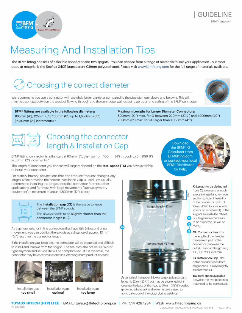
X: Length to be deducted from CL to ensure enough space to install and remove, and for sufficient flexibility of the connector (min. of 10 mm (25/64”) for in-line with little or no movement). If the spigots are installed off-set, or if large movements are to be expected, ‘X’ will be more).
CL: Connector Length - the length of the flexible, transparent part of the connector (between the cuffs). Standard lengths e.g. 100, 150, 200, 250 mm.
IG: Installation Gap - the distance in between both spigot ends - always slightly smaller than CL.
TS: Total space available between the two pipe ends that need to be connected.
A: Length of the upper & lower spigot tails; standard length is 52 mm (2 3/64”) but may be shortened right down to the base of the head to 37mm (1 1/2”) if needed (provided a heat sink and extreme care is used to avoid distortion of the spigot during welding).
The installation gap (IG) is the space to leave between the BFM® spigots.
This always needs to be slightly shorter than the connector length (CL).
Choosing the connector length & Installation Gap
Maximum Lengths for Larger Diameter Connectors: 500mm (20”) max. for Ø Between 700mm (271/2”) and 1,000mm (40”) 200mm (8”) max. for Ø Larger than 1,050mm (41”)
BFM® fittings are available in the following diameters: 100mm (4”), 125mm (5”), 150mm (6”) up to 1,650mm (65”) (in 50mm (2”) increments) *
Measuring And Installation Tips
Download the BFM® IG
Calculator from BFMfitting.com
or contact your local BFM® Distributor
for help.
Installation gap too small
Installation gap optimal
Installation gap too large
For static/vibratory applications that don’t require frequent changes, any length is fine provided the correct Installation Gap is used. We usually recommend installing the longest possible connector for most other applications, and for those with large movements (such as gyratory equipment), a minimum of around 300mm (12”) is best.
Spigot head = 37mm
Spigot head = 37mm
A
A
TS
XIG
CL
=-
Hea
d
| GUIDELINE
TUYAUX HITECH (HTP) LTÉE | EMAIL: [email protected] | PH: 514 426 1234 | WEB: www.hitechpiping.ca
BFMfitting.com+
Tuyaux HiTech (HTP) Ltée
V3 JUN 2018 PAGE 2 OF 2GUIDELINES - MEASURING & INSTALLATION TIPS
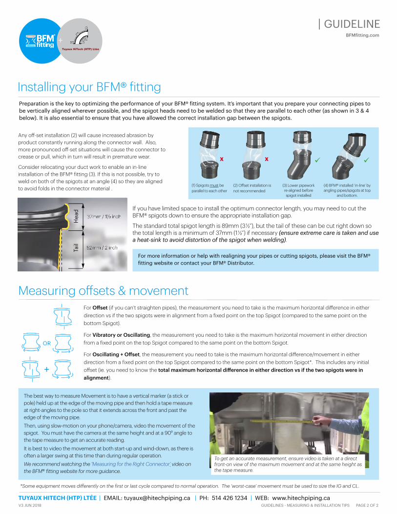
Installing your BFM® fittingPreparation is the key to optimizing the performance of your BFM® fitting system. It’s important that you prepare your connecting pipes to be vertically aligned wherever possible, and the spigot heads need to be welded so that they are parallel to each other (as shown in 3 & 4 below). It is also essential to ensure that you have allowed the correct installation gap between the spigots.
Any off-set installation (2) will cause increased abrasion by product constantly running along the connector wall. Also, more pronounced off-set situations will cause the connector to crease or pull, which in turn will result in premature wear.
Consider relocating your duct work to enable an in-line installation of the BFM® fitting (3). If this is not possible, try to weld on both of the spigots at an angle (4) so they are aligned to avoid folds in the connector material .
If you have limited space to install the optimum connector length, you may need to cut the BFM® spigots down to ensure the appropriate installation gap.
The standard total spigot length is 89mm (3 1/2”), but the tail of these can be cut right down so the total length is a minimum of 37mm (1 1/2”) if necessary (ensure extreme care is taken and use a heat-sink to avoid distortion of the spigot when welding).
For more information or help with realigning your pipes or cutting spigots, please visit the BFM® fitting website or contact your BFM® Distributor.
Measuring offsets & movementFor Offset (if you can’t straighten pipes), the measurement you need to take is the maximum horizontal difference in either direction vs if the two spigots were in alignment from a fixed point on the top Spigot (compared to the same point on the bottom Spigot).
For Vibratory or Oscillating, the measurement you need to take is the maximum horizontal movement in either direction from a fixed point on the top Spigot compared to the same point on the bottom Spigot.
For Oscillating + Offset, the measurement you need to take is the maximum horizontal difference/movement in either direction from a fixed point on the top Spigot compared to the same point on the bottom Spigot*. This includes any initial offset (ie. you need to know the total maximum horizontal difference in either direction vs if the two spigots were in alignment).
*Some equipment moves differently on the first or last cycle compared to normal operation. The ‘worst-case’ movement must be used to size the IG and CL.
The best way to measure Movement is to have a vertical marker (a stick or pole) held up at the edge of the moving pipe and then hold a tape measure at right-angles to the pole so that it extends across the front and past the edge of the moving pipe. Then, using slow-motion on your phone/camera, video the movement of the spigot. You must have the camera at the same height and at a 900 angle to the tape measure to get an accurate reading.It is best to video the movement at both start-up and wind-down, as there is often a larger swing at this time than during regular operation.We recommend watching the ‘Measuring for the Right Connector’ video on the BFM� fitting website for more guidance.
To get an accurate measurement, ensure video is taken at a direct front-on view of the maximum movement and at the same height as the tape measure.
OR
+
(2) Offset installation is not recommended
(3) Lower pipework re-aligned before spigot installed
(4) BFM® installed ‘in-line’ by angling pipes/spigots at top
and bottom.
(1) Spigots must be parallel to each other
X X