measuring flexural rigidity of mullite microfibers using magnetic
TRANSCRIPT

Measuring flexural rigidity of mullite microfibers using magnetic dropletsZhaoxi Chen, Yu Gu, Zhao Zhang, Konstantin G. Kornev, Igor Luzinov, and Fei Peng Citation: Journal of Applied Physics 117, 214304 (2015); doi: 10.1063/1.4921881 View online: http://dx.doi.org/10.1063/1.4921881 View Table of Contents: http://scitation.aip.org/content/aip/journal/jap/117/21?ver=pdfcov Published by the AIP Publishing Articles you may be interested in Direct measurement of shear properties of microfibers Rev. Sci. Instrum. 85, 095118 (2014); 10.1063/1.4895679 Droplet-induced deformation of a polymer microfiber J. Appl. Phys. 114, 044901 (2013); 10.1063/1.4816046 Noncontact quantitative spatial mapping of stress and flexural rigidity in thin membranes using a picosecondtransient grating photoacoustic technique J. Acoust. Soc. Am. 109, 547 (2001); 10.1121/1.1342005 Displacement of droplets and deformation of thin liquid layers using flexural vibrations of structures. Influence ofacoustic radiation pressure J. Acoust. Soc. Am. 107, 661 (2000); 10.1121/1.428566 Flexure Mounted Beam Balance for Long‐Term Magnetic Stability Measurements Rev. Sci. Instrum. 32, 1051 (1961); 10.1063/1.1717611
[This article is copyrighted as indicated in the article. Reuse of AIP content is subject to the terms at: http://scitation.aip.org/termsconditions. Downloaded to ] IP:
198.21.160.160 On: Mon, 01 Jun 2015 14:22:13
Measuring flexural rigidity of mullite microfibers using magnetic droplets
Zhaoxi Chen, Yu Gu, Zhao Zhang, Konstantin G. Kornev,a) Igor Luzinov, and Fei Penga)
Department of Materials Science and Engineering, Clemson University, Clemson, South Carolina 29634, USA
(Received 11 March 2015; accepted 18 May 2015; published online 1 June 2015)
Flexural rigidity of many microfibers is known to deviate from the Bernoulli-Euler predictions
that neglect shear deformations. We examine mullite microfibers formed by electrospinning of
sol-gel precursors. The formed fibers have diameters smaller than 10 lm. A magnetic drop was
placed on the free end of a dangling fiber, and the fiber was flexed by applying a non-uniform
magnetic field. By applying different magnetic fields, we generated a series of different fiber pro-
files and filmed the process of fiber bending. Mullite microfibers were found to follow the
Bernoulli-Euler predictions, and the shear deformations in the material were insignificant. This
was confirmed by employing the Euler elastica model to describe the fiber profiles. The bending
test provided a Young modulus of E¼ 100 GPa, which appeared to be very close to that found
from the tensile test. VC 2015 AIP Publishing LLC. [http://dx.doi.org/10.1063/1.4921881]
I. INTRODUCTION
Due to its brittleness, ceramic fiber readily suffers me-
chanical failure even at small deformations. This makes it
very difficult to handle the fibers without damaging them.1–6
To avoid this problem, the tensile test is typically conducted
on a thick ceramic fiber, with a diameter greater than tens of
micrometers.7–9 In addition, the load resolution of most com-
mercially available mechanical testing systems limits their
application to fiber diameters greater than 10 lm.1,3,10–14 Due
to these difficulties, microfibers are typically tested in strands
composed of many individual fibers,15–18 and then different
mathematical models have been employed to interpret the
data.19–21 Recently, some other approaches have been suc-
cessfully developed such as a modified tensile test, atomic
force microscopy, microcantilever vibration methods, beam
bending methods, and the nanoindentation method.22–29
Among these approaches, the fiber bending method assumes
the simplest experimental setup.1,26,27
Many microfibers experience significant shear deforma-
tions upon bending.30 Therefore, it is instructive to investi-
gate the flexural rigidity of microfibers by examining their
shape and comparing it with the Bernoulli-Euler or
Timoshenko predictions. Recently, we have developed a
novel, nondestructive method of testing micro and nanofibers
by applying a magnetic torque on the free end of a suspended
fiber.31 It has been shown that the fibers can be bowed with
small micro- and even nano-Newton forces.31 In this paper,
we apply this method to examine the flexural rigidity of ce-
ramic microfibers, using mullite microfibers as a proof-of-
concept example.
Mullite (3Al2O3�2SiO2) fibers have excellent mechani-
cal and chemical properties and have been widely used as
reinforcement in ceramic matrix composites.32–34 We syn-
thesized mullite fibers with diameters ranging from hundreds
of nanometers to micrometers by employing sol-gel/electro-
spinning followed by sintering.2 The microstructure and
mechanical properties of the e-spun mullite microfibers were
investigated. Then we studied the flexural rigidity of these
fibers by employing image analysis based on the Euler elas-
tica equations.
II. EXPERIMENTAL PROCEDURE
A. Fiber fabrication, phase identification, andmicrostructure characterization
Mullite (3Al2O3�2SiO2) microfibers were formed by elec-
trospinning a sol-gel derived precursor. As the alumina and
silica sources, we used aluminum isopropoxide (AIP,
Al(C3H7O)3, 98%, Alfa Aesar, MA, USA), aluminum nitrate
(AN, Al(NO3)3�9H2O, 98%, Alfa Aesar, MA, USA), and tet-
raethyl orthosilicate (TEOS, Si(OC2H5)4, 98%, Acros
Organics, NJ, USA). The molar ratio of the composition was
AIP:AN:TEOS¼ 11:4:5. AN was dissolved in deionized
water at room temperature by vigorous stirring for 30 min.
Then, AIP and TEOS were added into the solution and stirred
for 20 h. After AIP and TEOS were dissolved completely, a
clear solution was obtained. The solution was then refluxed at
80 �C for 5 h. Approximately 2/3 weight of the solvent was
evaporated using a rotary evaporator (IKA RV 10 digital,
IKA, China). The obtained solution was then held at 80 �C in
an oven until a viscous sol was formed. The time for concen-
trating the sol is typically 16–24 h, depending on the size and
shape of the container. A polyethylene oxide (PEO, MW
1 000 000, Aldrich, MO, USA) solution, 2 wt. % PEO in H2O,
was prepared separately as a spinning aid. The mullite sol (M)
was first diluted in ethanol (E) and then mixed with the spin-
ning aid (P) with a volume ratio of M:P:E¼ 4:1:2. This solu-
tion was used for electrospinning with a calculated mullite
yield of 28 grams per 100 ml. The fibers were electrospun
under an applied electric field, generated using a high voltage
power supply (Model PS/FC60P02.0-11, Glassman High
Voltage Inc, NJ, USA). A positive 10 kV voltage was applied
to the needle of a syringe containing e-dopes. The flow rate of
the syringe pump (Model NE-300, New Era Pump System
Inc, NY, USA) was set at 0.5 ml/h. The needle tip was placed
a)Authors to whom correspondence should be addressed. Electronic
addresses: [email protected] and [email protected].
0021-8979/2015/117(21)/214304/8/$30.00 VC 2015 AIP Publishing LLC117, 214304-1
JOURNAL OF APPLIED PHYSICS 117, 214304 (2015)
[This article is copyrighted as indicated in the article. Reuse of AIP content is subject to the terms at: http://scitation.aip.org/termsconditions. Downloaded to ] IP:
198.21.160.160 On: Mon, 01 Jun 2015 14:22:13

20 cm from the rotating dram collector, and fibers were pro-
duced at 25%–35% ambient relative humidity. The obtained
fibers were dried at 60 �C for 24 h before firing. The heating
rate was set at 1 �C/min to increase temperature from room
temperature to 500 �C, and then changed to 10 �C/min to
increase temperature above 500 �C. The fibers were kept at
1200 �C for 2 h.
The phase identification of the fiber material was per-
formed with an X-ray diffractometer (XRD, Rigaku Co.,
Ltd., Tokyo, Japan), and the microstructure was character-
ized using scanning electron microscopy (SEM, Hitachi
S4800, Hitachi, Ltd., Tokyo, Japan).
B. Tensile test
The single filament tensile tests were carried out using a
single filament tensile testing machine (Instron 5582, Instron
Ltd., High Wycombe, Buckinghamshire, UK). During each
test, a single mullite fiber was mounted and fixed using a
superglue onto a C-card. After fixing the frame with the fiber
on the test machine, the sides of the C-card were cut open
and the strain rate was set as 1 mm/min. A gauge length of
10 mm was used. The fiber diameters for each test were
measured using an optical microscope (Olympus BX51,
Olympus Optical Co. Ltd, Tokyo, Japan).
C. Bending test
A single 1 mm long fiber was glued to the glass substrate
at one end. The iron fillers (FerroTec, Santa Clara, CA) were
mixed with the superglue with a 1:1 weight ratio. The fiber
tip was immersed into the liquid and then the fiber was
pulled out. The residue droplet was dried in ambient atmos-
phere to form a magnetic tip. This magnetic glue was suffi-
ciently thick to solidify before slipping off of the fiber tip.
Figure 1 shows the procedure of attaching the drop to the
fiber tip. Magnetic moments of the deposited droplets were
measured by using an Alternating Gradient Magnetometer
(AGM 2900, Princeton Measurements Inc., NJ, USA). Once
the applied magnetic field is known, one can calculate the
applied force.
To control the magnetic force in the bending experi-
ment, a cone shaped magnet (SuperMagnetMan, 12.7 �12.7 mm, N50 grade) was placed on a movable stage as
shown in Figure 2. The central axis of the magnet was
aligned along the z axis. A detailed experimental protocol of
the fiber bending by this cone-shaped magnet can be found
elsewhere.31 Moving the magnet back and forth, one can
force the suspended fiber to bow. The process of the fiber
bowing was filmed with a camera, and then the images were
analyzed with the developed code.31
The available Tesla-meter probes are too large to
ensure the accuracy of the measured field distribution. We
therefore calculated the distribution of magnetic field in
the vicinity of the magnetic pole using COMSOLVR
4.2. The
simulated magnetic field was calibrated according to the
method of Ref. 31.
III. RESULTS
A. Fiber microstructure and phase identification
Figure 3 shows the SEM micrographs of electrospun
fibers before and after firing. The fibers obtained are straight
and uniform. No pores or defects were observed at the fiber
surface or its cross-sections. The XRD results on the mullite
sol after heat-treatment at 800 �C, 1000 �C, and 1200 �C are
shown in Figure 4. The labeled peaks indicate that the pure
mullite phase is the only phase formed during firing, as no
FIG. 1. Ferrofluid glue collected by
submersing the mullite fiber into the
iron filler loaded glue and then pulling
it out.
FIG. 2. Schematic of the experimental setup. The center of the Cartesian
system of coordinates is taken at the clamped end of the suspended fiber.
The coordinates of the fiber tip are (x0, z0), and of the magnetic pole tip are
(xm, zm). The angle h is formed by the tangential line to the fiber bow and
the z-axis.
214304-2 Chen et al. J. Appl. Phys. 117, 214304 (2015)
[This article is copyrighted as indicated in the article. Reuse of AIP content is subject to the terms at: http://scitation.aip.org/termsconditions. Downloaded to ] IP:
198.21.160.160 On: Mon, 01 Jun 2015 14:22:13
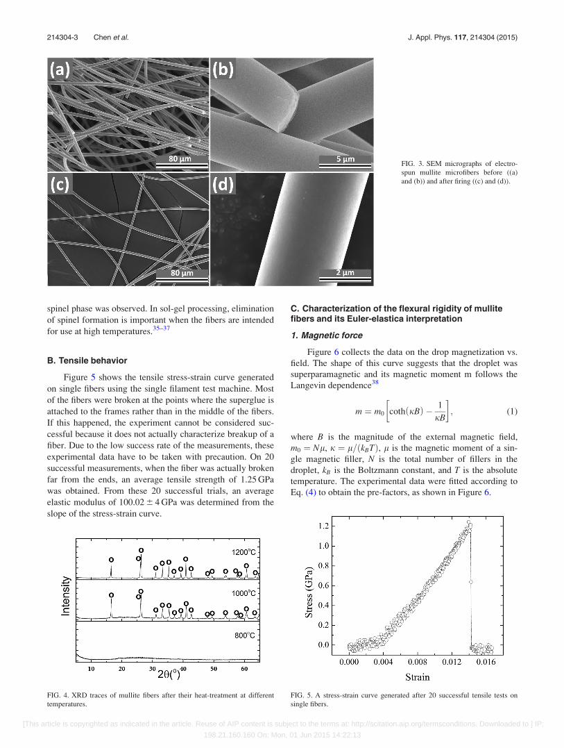
spinel phase was observed. In sol-gel processing, elimination
of spinel formation is important when the fibers are intended
for use at high temperatures.35–37
B. Tensile behavior
Figure 5 shows the tensile stress-strain curve generated
on single fibers using the single filament test machine. Most
of the fibers were broken at the points where the superglue is
attached to the frames rather than in the middle of the fibers.
If this happened, the experiment cannot be considered suc-
cessful because it does not actually characterize breakup of a
fiber. Due to the low success rate of the measurements, these
experimental data have to be taken with precaution. On 20
successful measurements, when the fiber was actually broken
far from the ends, an average tensile strength of 1.25 GPa
was obtained. From these 20 successful trials, an average
elastic modulus of 100.02 6 4 GPa was determined from the
slope of the stress-strain curve.
C. Characterization of the flexural rigidity of mullitefibers and its Euler-elastica interpretation
1. Magnetic force
Figure 6 collects the data on the drop magnetization vs.
field. The shape of this curve suggests that the droplet was
superparamagnetic and its magnetic moment m follows the
Langevin dependence38
m ¼ m0 coth jBð Þ � 1
jB
� �; (1)
where B is the magnitude of the external magnetic field,
m0 ¼ Nl, j ¼ l=ðkBTÞ, l is the magnetic moment of a sin-
gle magnetic filler, N is the total number of fillers in the
droplet, kB is the Boltzmann constant, and T is the absolute
temperature. The experimental data were fitted according to
Eq. (4) to obtain the pre-factors, as shown in Figure 6.
FIG. 3. SEM micrographs of electro-
spun mullite microfibers before ((a)
and (b)) and after firing ((c) and (d)).
FIG. 4. XRD traces of mullite fibers after their heat-treatment at different
temperatures.
FIG. 5. A stress-strain curve generated after 20 successful tensile tests on
single fibers.
214304-3 Chen et al. J. Appl. Phys. 117, 214304 (2015)
[This article is copyrighted as indicated in the article. Reuse of AIP content is subject to the terms at: http://scitation.aip.org/termsconditions. Downloaded to ] IP:
198.21.160.160 On: Mon, 01 Jun 2015 14:22:13

It is important to see that the drop magnetization follows
the Langevin dependence. This dependence suggests that the
magnetic moment of the droplet should be co-aligned with
the field and the drop should not exert any spontaneous tor-
que associated with the misalignment of the magnetic
moments of the fillers.39,40
This implies that the bending force exerted on the fiber
tip is induced only by the magnetic field gradient
F ¼ ðm � rÞB: (2)
As shown in Ref. 31, the axial z-component of magnetic
force is much stronger than its transverse x-component.
Figure 7 shows the magnitude of magnetic field and the
z-component of magnetic force acting on the fiber tip posi-
tioned at (x0, z0) as a function of the axial distance
z¼ zm� z0 measured from the pole of a cone-shaped magnet,
where the z-coordinate of the pole (zm) is defined in Figure
2. With the known distance z¼ zm� z0, we can calculate the
magnetic force according to Eqs. (1) and (2).
2. Bow profile
A series of snapshots taken during the bending test are
shown in Figure 8. The fiber had a length of 0.64 mm
(measured from the fixed-end to the free-end) and diameter
of 4.5 lm. The fiber started to flex to the left in frame 1 and
continued to bow with increasing deflection when the mag-
net was approaching the fiber. As shown above, the torque
on the tip was negligible and the fiber bent because of the
field gradient. The magnitudes of forces exerted onto the
fiber tip as well as the tip coordinates are summarized in
Table I. The change of the x coordinate is initially small, i.e.,
the tip moves almost along the z-axis. A noticeable displace-
ment of the fiber tip from the magnet axis can be seen in
frames 7�9. The angle of the force vector in Table I was
calculated from the magnetic field distribution as discussed
in Ref. 31.
After bending, the fibers took on their original configu-
ration, parallel to the vertical axis (as shown in the support-
ing video). This fact suggests that the stresses have been
completely relaxed and the fibers have not acquired any irre-
versible or plastic deformations.
3. Interpretation of the bending experimentswith the Euler elastica model
Taking into account the complete recovery of the fiber
shape after deformations, it is natural to assume that the ma-
terial is purely elastic. Moreover, we will use the Euler elas-
tica model that neglects any shear deformations in the
material41
IEd2hdl2� F sin h ¼ 0; (3)
where E is the elastic modulus; I is the second moment of
inertia; l is the arclength, 0< l<L, where L is the fiber
length; h is the angle formed by the tangential line at the
point with arclength l with the z-axis; and F is the applied
magnetic force. For a fiber with the circular cross-section,
the second moment of inertia is I¼pd4/64, where d is the
fiber diameter.41 Since the x-component of the magnetic
force is much smaller than the axial z-component, the prob-
lem is simplified by assuming that the force F acts only in
the z-direction. The weight of the droplet is also negligible.
From the dimension of the droplet shown in Figure 8, we
estimated the gravitational force on the order of 10�9 N. The
magnetic forces employed are in the micronewton range,
which is at least two orders of magnitude greater than the
weight of the droplet. We impose the following boundary
conditions to solve Eq. (3):
h ¼ p2
at l ¼ 0;
dhdl¼ 0 at l ¼ L:
8><>: (4)
With the known I and F parameters, one can reproduce the
fiber profiles and compare them with the experimental ones.
However, since the elastic modulus E was not known in
advance, we needed to run a series of experiments adjusting
E in order to fit the fiber bows.
In order to determine elastic modulus E, we numerically
solved the Euler elastica equation with the specified boundary
conditions. A comparison of the experimental and theoretical
FIG. 6. Magnetization of the fiber tips versus magnetic field. Langevin func-
tion describes experimental data points fairly well.
FIG. 7. The strength of magnetic field and the z- component of magnetic
force as the functions of the distance between the fiber tip and the tip of a
magnet pole.
214304-4 Chen et al. J. Appl. Phys. 117, 214304 (2015)
[This article is copyrighted as indicated in the article. Reuse of AIP content is subject to the terms at: http://scitation.aip.org/termsconditions. Downloaded to ] IP:
198.21.160.160 On: Mon, 01 Jun 2015 14:22:13

fiber profiles was done at a sequence of points (xi,zi)
(i¼ 1,2…N) shown in Figure 9. A Matlab program allows
one to determine elastic modulus, E, corresponding to the best
fit of the experimental and theoretical fiber profiles.
Figure 9 collects the results of numeric fit of the fiber
profiles given in frames 2–8 of Figure 8. The solid curves
correspond to the theoretical fiber profile according to the
numerical Euler elastica solution. The solid symbols corre-
spond to the experimental data points. It is evident that the
Euler elastica model describes the fiber profiles fairly well.
The extracted elastic modules are summarized in Table II.
An average value of E¼ 104.8 6 5.7 GPa was obtained from
frames 2–6 in Figure 8 when the fiber tip was not moving far
away from the magnet axis.
In order to verify the obtained results, we applied
another method developed in Ref. 31. This method takes
advantage of the analytical solution of the Euler-elastica
model41
L ¼ffiffiffiffiffiffiEI
2F
rA h0ð Þ; A h0ð Þ ¼
ðp=2
h0
dhffiffiffiffiffiffiffiffiffiffiffiffiffiffiffiffiffiffiffiffiffiffiffiffiffiffiffifficos h0 � cos hp ; (5)
FIG. 8. Fiber bending by magnetic
field. (Multimedia view) [URL: http://
dx.doi.org/10.1063/1.4921881.1]
TABLE I. Force-position data of the fiber tip (the force direction is defined as the angle formed by the force vector and x-axis shown in Figure 2).
Frame number Force magnitude (lN) Force direction (deg) Tip coordinate z0 (mm) Tip coordinate x0 (mm)
1 0.675 90.0 0.019 0.640
2 0.789 90.0 0.027 0.640
3 0.918 90.0 0.032 0.640
4 1.088 90.0 0.038 0.640
5 1.304 90.0 0.048 0.640
6 1.641 90.0 0.070 0.640
7 2.139 89.8 0.100 0.636
8 3.198 88.9 0.172 0.618
9 6.369 86.3 0.300 0.565
FIG. 9. Numerical solutions of the
Euler elastica model over imposed on
the experimental fiber profiles repre-
sented by the solid symbols.
214304-5 Chen et al. J. Appl. Phys. 117, 214304 (2015)
[This article is copyrighted as indicated in the article. Reuse of AIP content is subject to the terms at: http://scitation.aip.org/termsconditions. Downloaded to ] IP:
198.21.160.160 On: Mon, 01 Jun 2015 14:22:13
z0 ¼ffiffiffiffiffiffiEI
2F
rB h0ð Þ; B h0ð Þ ¼
ðp=2
h0
cos hffiffiffiffiffiffiffiffiffiffiffiffiffiffiffiffiffiffiffiffiffiffiffiffiffiffiffifficos h0 � cos hp dh;
x0 ¼ffiffiffiffiffiffiffiffi2EI
F
rcos h0;
8>>>><>>>>:
(6)
where h0 is the angle formed by the tangential line at the
fiber tip and the z-axis. For fiber configurations having
cos h0 < 0:5, the analytical solution (6) can be approximated
by polynomial functions to give useful relations between the
applied force and coordinates of the fiber tip31
F � 3:19EIz0=L3; (7)
x0 � L� 0:615z20=L: (8)
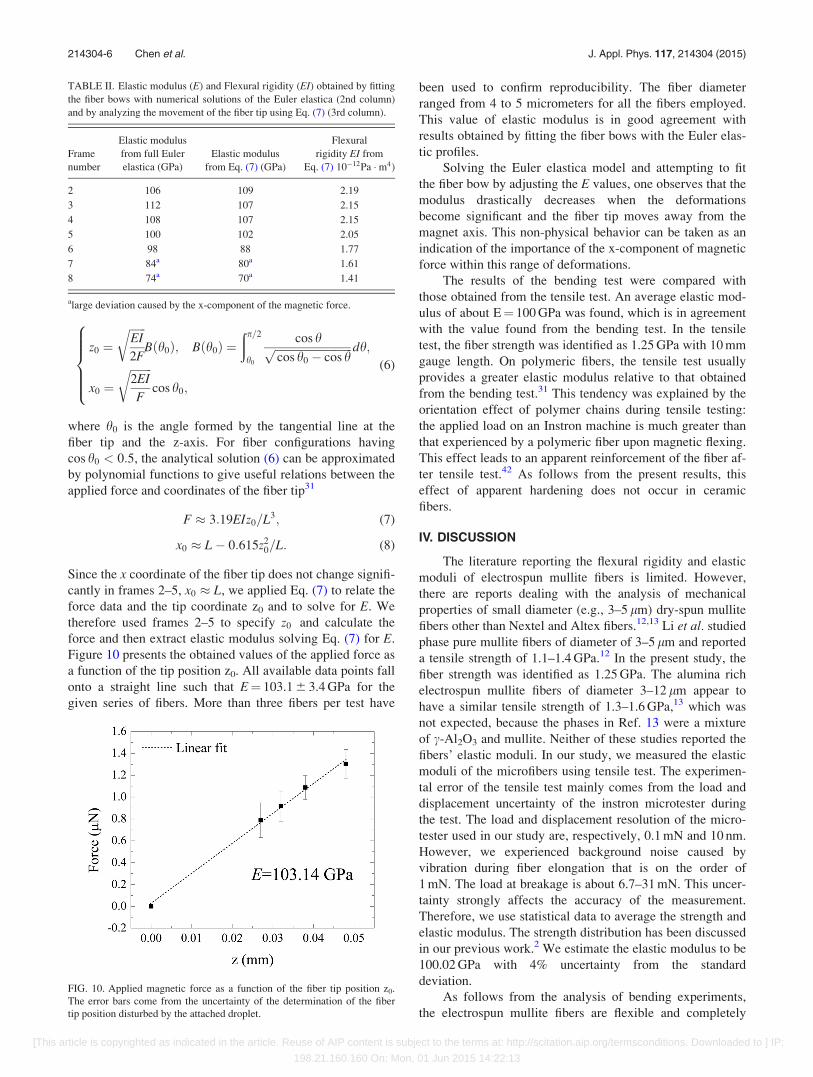
Since the x coordinate of the fiber tip does not change signifi-
cantly in frames 2–5, x0 � L, we applied Eq. (7) to relate the
force data and the tip coordinate z0 and to solve for E. We
therefore used frames 2–5 to specify z0 and calculate the
force and then extract elastic modulus solving Eq. (7) for E.
Figure 10 presents the obtained values of the applied force as
a function of the tip position z0. All available data points fall
onto a straight line such that E¼ 103.1 6 3.4 GPa for the
given series of fibers. More than three fibers per test have
been used to confirm reproducibility. The fiber diameter
ranged from 4 to 5 micrometers for all the fibers employed.
This value of elastic modulus is in good agreement with
results obtained by fitting the fiber bows with the Euler elas-
tic profiles.
Solving the Euler elastica model and attempting to fit
the fiber bow by adjusting the E values, one observes that the
modulus drastically decreases when the deformations
become significant and the fiber tip moves away from the
magnet axis. This non-physical behavior can be taken as an
indication of the importance of the x-component of magnetic
force within this range of deformations.
The results of the bending test were compared with
those obtained from the tensile test. An average elastic mod-
ulus of about E¼ 100 GPa was found, which is in agreement
with the value found from the bending test. In the tensile
test, the fiber strength was identified as 1.25 GPa with 10 mm
gauge length. On polymeric fibers, the tensile test usually
provides a greater elastic modulus relative to that obtained
from the bending test.31 This tendency was explained by the
orientation effect of polymer chains during tensile testing:
the applied load on an Instron machine is much greater than
that experienced by a polymeric fiber upon magnetic flexing.
This effect leads to an apparent reinforcement of the fiber af-
ter tensile test.42 As follows from the present results, this
effect of apparent hardening does not occur in ceramic
fibers.
IV. DISCUSSION
The literature reporting the flexural rigidity and elastic
moduli of electrospun mullite fibers is limited. However,
there are reports dealing with the analysis of mechanical
properties of small diameter (e.g., 3–5 lm) dry-spun mullite
fibers other than Nextel and Altex fibers.12,13 Li et al. studied
phase pure mullite fibers of diameter of 3–5 lm and reported
a tensile strength of 1.1–1.4 GPa.12 In the present study, the
fiber strength was identified as 1.25 GPa. The alumina rich
electrospun mullite fibers of diameter 3–12 lm appear to
have a similar tensile strength of 1.3–1.6 GPa,13 which was
not expected, because the phases in Ref. 13 were a mixture
of c-Al2O3 and mullite. Neither of these studies reported the
fibers’ elastic moduli. In our study, we measured the elastic
moduli of the microfibers using tensile test. The experimen-
tal error of the tensile test mainly comes from the load and
displacement uncertainty of the instron microtester during
the test. The load and displacement resolution of the micro-
tester used in our study are, respectively, 0.1 mN and 10 nm.
However, we experienced background noise caused by
vibration during fiber elongation that is on the order of
1 mN. The load at breakage is about 6.7–31 mN. This uncer-
tainty strongly affects the accuracy of the measurement.
Therefore, we use statistical data to average the strength and
elastic modulus. The strength distribution has been discussed
in our previous work.2 We estimate the elastic modulus to be
100.02 GPa with 4% uncertainty from the standard
deviation.
As follows from the analysis of bending experiments,
the electrospun mullite fibers are flexible and completely
TABLE II. Elastic modulus (E) and Flexural rigidity (EI) obtained by fitting
the fiber bows with numerical solutions of the Euler elastica (2nd column)
and by analyzing the movement of the fiber tip using Eq. (7) (3rd column).
Frame
number
Elastic modulus
from full Euler
elastica (GPa)
Elastic modulus
from Eq. (7) (GPa)
Flexural
rigidity EI from
Eq. (7) 10�12Pa �m4)
2 106 109 2.19
3 112 107 2.15
4 108 107 2.15
5 100 102 2.05
6 98 88 1.77
7 84a 80a 1.61
8 74a 70a 1.41
alarge deviation caused by the x-component of the magnetic force.
FIG. 10. Applied magnetic force as a function of the fiber tip position z0.
The error bars come from the uncertainty of the determination of the fiber
tip position disturbed by the attached droplet.
214304-6 Chen et al. J. Appl. Phys. 117, 214304 (2015)
[This article is copyrighted as indicated in the article. Reuse of AIP content is subject to the terms at: http://scitation.aip.org/termsconditions. Downloaded to ] IP:
198.21.160.160 On: Mon, 01 Jun 2015 14:22:13

recover their initial state after a vigorous bending. The fiber
bow is completely described by the Euler elastica model.
Thus, the shear deformations in the fiber are not significant.
This confirms that the polymers added in small quantities to
facilitate electrospinning of mullite fibers do not influence
the mechanical properties of the resulting ceramic. With a
greater concentration of the polymer spinning aid, one usu-
ally observes a porous microstructure left after burning off
the polymer.43 In the present study, the microfibers were syn-
thesized by carefully choosing the composition of inorganic
precursor to provide a high yield of mullite during hydroly-
sis. This enabled us to significantly reduce the polymer con-
tent and improve the structural and mechanical properties of
the mullite fibers.
Flexibility of a fiber is a very important engineering pa-
rameter that is worth discussing in some detail. Compared to
other micrometer thick fibers, mullite e-spun fibers demon-
strate a high degree of flexibility defined as f¼ 1/(EI), which
is very sensitive to the inverse function of fiber diameter d.
In Table III, we see that the flexibility of mullite microfibers
(obtained and averaged from frames 2–5 in Table II) reaches
470� 109 N�1 �m�2, which is at least one order of magni-
tude greater than the flexibility of other types of microfibers
with a diameter around 10 lm, such as PAN-based carbon
fibers (HM and HS) and commercial oxide fibers (NextelTM
720). This flexibility facilitates the weaving, braiding, wind-
ing, and twisting process that are used to produce yarns, fab-
rics, and other complex texture for use as reinforcement in a
matrix material. On the other hand, the obtained mullite
fibers demonstrate a moderate elastic modulus (103 GPa)
that is comparable to the value of E-glass (125 GPa) and
Kevlar 49 fibers (70 GPa), which are commonly used to rein-
force polymer materials.44,45 A great advantage of mullite
e-spun fibers over the most of the microfibers listed in Table
III rests in their excellent high temperature mechanical prop-
erties and inherent chemical stability in oxidizing environ-
ment. This will make them attractive candidates in
generating advanced ceramic composites materials for
extreme applications.
V. CONCLUSIONS
Mullite microfibers were electrospun, and their phase
composition was studied. In order to evaluate the flexural ri-
gidity and elastic modulus of these microfibers, we applied
recently developed methods of fiber bending where a mag-
netic drop was glued to the fiber tip and the fiber was flexed
by a permanent magnet.31 In parallel, we used a standard
tensile test. It was shown that the fibers completely recover
their initial configuration after removing the load. This result
suggests that the fibers deform in the purely elastic mode.
Using the Euler elastic model, we were able to describe the
fiber bows. Therefore, the shear deformations in ceramic
fibers are not significant. In the tensile test, the elastic modu-
lus of E¼ 100 GPa and the fiber strength 1.25 GPa were
obtained. In the bending test, the flexural rigidity of 2:06
�10�12 Pa �m4 and elastic modulus of E¼ 103 Ga were
obtained. These results indicate that mullite microfibers are
flexible and, due to their microstructural uniformity, do not
generate significant shear stresses during bending.
ACKNOWLEDGMENTS
This project was funded by the Air Force Office of
Scientific Research, Contract No. FA9550-12-1-0459. The
authors would like to express their appreciation for the
helpful suggestions and support of their contract monitor,
Dr. Ali Sayir.
1E. P. S. Tan and C. T. Lim, Rev. Sci. Instrum. 75, 2581 (2004).2Z. Chen, Z. Zhang, C. C. Tsai, K. Kornev, I. Luzinov, M. Fang, and F.
Peng, J. Sol-Gel Sci. Technol. 74, 208 (2015).3E. P. S. Tan and C. T. Lim, Compos. Sci. Technol. 66, 1102 (2006).4M. Yu, M. J. Dyer, G. D. Skidmore, H. W. Rohrs, X. Lu, K. D. Ausman,
J. R. V. Ehr, and R. S. Ruoff, Nanotechnology 10, 244 (1999).5X. Wang, Micro/nano Mechanical Characterization of One-dimensionalNanomaterials and Biomaterials (ProQuest, 2008).
6G. Motz and R. K. Bordia, Handbook of Textile Fibre Structure: Natural,Regenerated, Inorganic and Specialist Fibres (Woodhead Publishing,
2009), Vol. 2, p. 378.7P. E. Cantonwine, J. Mater. Sci. 38, 461 (2003).8D. M. Wilson and L. R. Visser, Compos. Part A: Appl. Sci. Manuf. 32,
1143 (2001).9S. Yajima, K. Okamura, J. Hayashi, and M. Omori, J. Am. Ceram. Soc.
59, 324 (1976).10F. Deleglise, M. H. Berger, D. Jeulin, and A. R. Bunsell, J. Eur. Ceram.
Soc. 21, 569 (2001).11X. Wang, C. Gong, and G. Fan, Mater. Res. Bull. 46, 2398 (2011).12C. S. Li, Y. J. Zhang, and J. D. Zhang, J. Inorg. Mater. 24(4), 848 (2009).13M. Chatterjee, M. K. Naskar, P. K. Chakrabarty, and D. Ganguli, J. Sol-
Gel Sci. Technol. 25, 169 (2002).14J. J. Petrovic and R. C. Hoover, J. Mater. Sci. 22, 517 (1987).15K. Charlet, J. P. Jernot, M. Gomina, L. Bizet, and J. Br�eard, J. Compos.
Mater. 44, 2887 (2010).16W. A. Curtin, A. N. Netravali, and J. M. Park, J. Mater. Sci. 29, 4718
(1994).17X. F. Wu and Y. A. Dzenis, J. Appl. Phys. 98, 093501 (2005).18Z. W. Pan, S. S. Xie, L. Lu, B. H. Chang, L. F. Sun, W. Y. Zhou, G.
Wang, and D. L. Zhang, Appl. Phys. Lett. 74, 3152 (1999).19Y. Wang and Y. Xia, Compos. Part A: Appl. Sci. Manuf. 29, 1411 (1998).20A. Mishra and N. K. Naik, J. Compos. Mater. 43, 1199 (2009).21C. T. Sun and J. L. Chen, Compos. Sci. Technol. 40, 115 (1991).22S. H. Lee, C. Tekmen, and W. M. Sigmund, Mater. Sci. Eng.: A 398, 77
(2005).23R. Inai, M. Kotaki, and S. Ramakrishna, Nanotechnology 16, 208 (2005).24E. P. S. Tan, C. N. Goh, C. H. Sow, and C. T. Lim, Appl. Phys. Lett. 86,
073115 (2005).25E. P. S. Tan and C. T. Lim, Appl. Phys. Lett. 87, 123106 (2005).26E. P. S. Tan and C. T. Lim, Appl. Phys. Lett. 84, 1603 (2004).27L. M. Bellan, J. Kameoka, and H. G. Craighead, Nanotechnology 16, 1095
(2005).28P. A. Yuya, Y. Wen, J. A. Turner, Y. A. Dzenis, and Z. Li, Appl. Phys.
Lett. 90, 111909 (2007).29X. Li, H. Gao, C. J. Murphy, and K. K. Caswell, Nano Lett. 3, 1495
(2003).30S. Timoshenko and J. M. Gere, Mechanics of Materials (Van Nostrand
Reinhold Co., New York, 1972).
TABLE III. Elastic properties of common microfibers.46,47
Materials
(fibers)
Diameter
(lm)
Elastic modulus
(GPa)
Flexibility
(109 N�1�m�2)
E-spun mullite 4.5 103 470
E-glass 14 70 7.5
PAN-based carbon, HM 10 390 5.2
PAN-based carbon, HS 8 250 19
Kevlar 49 12 125 7.8
NextelTM 720 10–12 260 3.8–7.8
214304-7 Chen et al. J. Appl. Phys. 117, 214304 (2015)
[This article is copyrighted as indicated in the article. Reuse of AIP content is subject to the terms at: http://scitation.aip.org/termsconditions. Downloaded to ] IP:
198.21.160.160 On: Mon, 01 Jun 2015 14:22:13

31Y. Gu and K. G. Kornev, Soft Matter 10, 2816 (2014).32K. K. Chawla, Z. R. Xu, and J. S. Ha, J. Eur. Ceram. Soc. 16, 293 (1996).33H. Schneider, J. Schreuer, and B. Hildmann, J. Eur. Ceram. Soc. 28, 329
(2008).34C. Kaya, E. G. Butler, A. Selcuk, A. R. Boccaccini, and M. H. Lewis,
J. Eur. Ceram. Soc. 22, 2333 (2002).35U. Selvaraj, S. Komarneni, and R. Roy, J. Solid State Chem. 106, 73
(1993).36D. J. Cassidy, J. L. Woolfrey, J. R. Bartlett, and B. Ben-Nissan, J. Sol-Gel
Sci. Technol. 10, 19 (1997).37T. Ban, S. Hayashi, A. Yasumori, and K. Okada, J. Eur. Ceram. Soc. 16,
127 (1996).38R. E. Rosensweig, Ferrohydrodynamics (Cambridge University Press,
1985).39J. J. Newman and R. B. Yarbrough, J. Appl. Phys. 39, 5566 (1968).
40E. Blums, A. Cebers, and M. M. Maiorov, Magnetic Fluids (Walter de
Gruyter, 1997).41L. D. Landau, E. M. Lifshitz, A. M. Kosevich, and L. P. Pitaevskii, Theory
of Elasticity (Pergamon Press, 1986).42D. R. Salem, Structure Formation in Polymeric Fibers (Hanser Verlag,
2001).43W. Sigmund, J. Yuh, H. Park, V. Maneeratana, G. Pyrgiotakis, A. Daga, J.
Taylor, and J. C. Nino, J. Am. Ceram. Soc. 89, 395 (2006).44B. Z. Jang, Compos. Sci. Technol. 44, 333 (1992).45L. Kumosa, D. Armentrout, and M. Kumosa, Compos. Sci. Technol. 61,
615 (2001).46K. K. Chawla, Composite Materials: Science and Engineering (Springer
Science & Business Media, 2012).473M company, 3M Nextel Ceramic Textiles Technical Notebook (3M
Ceramic Fibers and Textiles, St. Paul, MN, 2001).
214304-8 Chen et al. J. Appl. Phys. 117, 214304 (2015)
[This article is copyrighted as indicated in the article. Reuse of AIP content is subject to the terms at: http://scitation.aip.org/termsconditions. Downloaded to ] IP:
198.21.160.160 On: Mon, 01 Jun 2015 14:22:13