mecablitz 45 cl-4 - freeebgy.free.fr/photo/docs/45cl4_e.pdf · 41 point worth knowing the mecablitz...
TRANSCRIPT

MECABLITZ 45 CL-4Bedienungsanleitung Mode d’emploiGebruiksaanwijzing Operating instructionManuale istruzioni Manual de instrucciones

40
�
ContentsForeword . . . . . . . . . . . . . . . . . . . . . . . . . . . . . . . . . . . . . . . . . 40Points worth knowing . . . . . . . . . . . . . . . . . . . . . . . . . . . . . . . . . 41Special flash functions . . . . . . . . . . . . . . . . . . . . . . . . . . . . . . . . 41
1. Safety instructions . . . . . . . . . . . . . . . . . . . . . . . . . . . . . . . . . . . 432. Preparing the flashgun for use. . . . . . . . . . . . . . . . . . . . . . . . . . . 432.1 Attaching the flashgun to a camera . . . . . . . . . . . . . . . . . . . . . . . 432.2 Power supply . . . . . . . . . . . . . . . . . . . . . . . . . . . . . . . . . . . . . . . 432.3 Battery replacement . . . . . . . . . . . . . . . . . . . . . . . . . . . . . . . . . . 442.3.1 Exchanging the batteries. . . . . . . . . . . . . . . . . . . . . . . . . . . . . . . 442.3.2 Operation with the battery pack . . . . . . . . . . . . . . . . . . . . . . . . . 442.3.3 Operation with the mains unit . . . . . . . . . . . . . . . . . . . . . . . . . . . 442.4 Switching the flashgun on and off . . . . . . . . . . . . . . . . . . . . . . . . 443. TTL flash mode. . . . . . . . . . . . . . . . . . . . . . . . . . . . . . . . . . . . . . 444. Automatic flash mode. . . . . . . . . . . . . . . . . . . . . . . . . . . . . . . . . 455. Manual flash mode . . . . . . . . . . . . . . . . . . . . . . . . . . . . . . . . . . 466. Bounced flash . . . . . . . . . . . . . . . . . . . . . . . . . . . . . . . . . . . . . . 466.1 Bounced flash with activated secondary reflector . . . . . . . . . . . . . 466.2 Bounced flash in automatic and TTL flash modes. . . . . . . . . . . . . . 476.3 Bounced flash in manual flash mode . . . . . . . . . . . . . . . . . . . . . . 477. Winder mode . . . . . . . . . . . . . . . . . . . . . . . . . . . . . . . . . . . . . . 478. Fill-in flash in daylight . . . . . . . . . . . . . . . . . . . . . . . . . . . . . . . . 478.1 Fill-in flash in automatic mode. . . . . . . . . . . . . . . . . . . . . . . . . . . 478.2 Fill-in flash in manual mode . . . . . . . . . . . . . . . . . . . . . . . . . . . . 488.3 Fill-in flash in TTL mode . . . . . . . . . . . . . . . . . . . . . . . . . . . . . . . 489. Auto-check display. . . . . . . . . . . . . . . . . . . . . . . . . . . . . . . . . . . 4810. Illumination and wide-angle diffuser . . . . . . . . . . . . . . . . . . . . . . 4811. Exposure corrections . . . . . . . . . . . . . . . . . . . . . . . . . . . . . . . . . 4911.1 Exposure correction in automatic flash mode . . . . . . . . . . . . . . . . 4911.2 Exposure correction in TTL flash mode . . . . . . . . . . . . . . . . . . . . . 4912. Care and maintenance . . . . . . . . . . . . . . . . . . . . . . . . . . . . . . . . 4913. Technical data . . . . . . . . . . . . . . . . . . . . . . . . . . . . . . . . . . . . . . 4914. Optional accessories . . . . . . . . . . . . . . . . . . . . . . . . . . . . . . . . . 50
ForewordCongratulations on purchasing this METZ flashgun, and thank you for yourconfidence in METZ equipment.It is only natural that you should want to use your flashgun straight away.However, it will be well worth your while to study these OperatingInstructions carefully beforehand to ensure that you can operate the flashguneffectively and without any problems.
Please also oppen the back cover page with the illustrations.
This flashgun can be used with:• All cameras with a hot shoe in conjunction with the synch cable 45-54
(optional accessory).• All cameras with synch connection in conjunction with the supplied synch
cable.• System cameras
Optimal adaptation to your camera is achieved by using an SCA adapter.The enclosed SCA 300/3002 table will indicate the adapter you requirefor your particular camera model. This table also indicates the special flashfunctions that can then be completed by the given system.
Brief survey of the operating functions:Configuration and operating modes• 45 CL-4 with synch cable:
Automatic flash mode, Ch. 4, Page 45.Manual flash mode, Ch. 5, Page 46.
• 45 CL-4 with SCA 300/3002-adapter:Automatic flash mode, Ch. 4, Page 45.TTL-flash mode*, Ch. 3, Page 44.Manual flash mode, Ch. 5, Page 46.
*Provided that the camera performs this function.
�

41
�
Point worth knowingThe mecablitz 45 CL-4 is available in two versions:• mecablitz 45 CL-4-NC
(with NiCad battery and battery charger)The NC version can be expanded to alkaline manganese battery operationby way of the battery holder 45-39 (available as an optional extra).
• mecablitz 45 CL-4-BAT (for operation with alkaline manganese batteries,batteries are not included)The battery version can be upgraded to rechargeable NiCad battery opera-tion by adding the B 45 charger set (= NiCad battery and battery charger)
Outstanding features:• Universal, swivelling quadrolight reflector for bounced flash without having
to forgo the benefits of automatic exposure control.• Secondary reflector that can be activated for front fill-in light with bounced
flash exposures.• Wide-angle diffuser with automatic data display changeover.• Automatic exposure control with a selection of 6 working apertures to easi-
ly resolve the problems associated with depth-of-field and to offer greatercreative scope regarding camera settings.
• Power-saving thyristor light output control, particularly in the close-up ran-ge, for shorter recycle times and a higher number of flashes from just onebattery charge
• Correct exposure confirmation (auto check) with a long display duration.• Convenient calculator dial for all settings.• Manual mode at full, half and quarter light output.• Operation with winder cameras.• Operating mode indicated by luminous display.• SCA 300 dedicated system. Adapters (optional accessories) will match the
mecablitz with the special functions of different system cameras. Pleaserefer to the enclosed SCA 300/3002 table to establish which adapter is
required for the given camera. The table also lists the special flash func-tions which the system can then perform.
Special flash functionswhen using an SCA 300 adapter:• Flash-ready indication in the camera’s viewfinder.• Correct exposure indication (auto check) in the camera’s viewfinder
A signal in the viewfinder of many cameras indicates correct exposure orunder-exposure of the film when in automatic or TTL flash mode.
• Automatic flash synch speed controlWith most system cameras flash readiness causes the shutter speed to beautomatically changed from the adjusted mode to flash synch speed. Onsome cameras slower adjusted shutter speeds are retained. The originalshutter speed is automatically readjusted on the camera as soon as theflash-ready display has extinguished, or when the flashgun is switched off.
• TTL flash control• Triggering control
The flash is not fired if, as a result of the aperture set on the lens in keepingwith the prevailing ambient light level, a shutter speed is adjusted on thecamera that equals or is faster than the flash synch speed. The picture isthen shot with the ambient light, thereby avoiding overexposure.
• First- or second-blind synchronization optionThis mode offers two possibilities of flash synchronization:- Either when the first blind of the focal plane shutter opens, or - just before closure of the second blind.The required synchronization is selected on the SCA adapter.Synchronization with the secon shutter blind is valuable when a slow shut-ter speed has to be used to shoot a moving object that has its own sourceof light.
• Autofocus measuring beamThe autofocus measuring beam is activated by the camera’s electronic

42
�
system as soon as the ambient light level is no longer sufficient for automa-tic focusing. The autofocus ermitter emits a striped pattern. If an SCA 300autofocus adapter is used, only the autofocus measuring beam built intothe adapter is activated.
• Program auto flash modeSome cameras merge in the „Program“ mode the ambient light with thelight emitted by the flashgun. The camera automatically adjusts a shutterspeed/aperture combination, and controls the flash in TTL mode.Operation of the flash/camera combination thus becomes very simple.
when using an SCA 3002 adapter all SCA 300 functions can be perfor-med, plus:• TTL fill-in flash control
Some system cameras offer TTL fill-in flash control in addition to the stan-dard TTL flash control mode. This operating mode is used for daylightexposures to brighten up dense shadows and for shots against the light(contre-jour). The camera’s, in conjunction with internal sensor measure-ment within the camera, ensures that the correct amount of flash light isemitted to achieve a balanced exposure. The camera automatically per-forms the flash exposure correction that is necessary for fill-in flash shots.
• TTL flash exposure correctionThere are certain photographic situations where the camera’s internal sen-sor can be deceived. This can be particularly the case with a dark subjectin front of a bright background (the subject is overexposed). To overcomethis problem in such a photographic situation an still achieve a correct epo-sure in the TTL flash mode, some cameras can influence the flash power ofthe flashgun. All elements of an exposure are influenced by normal expo-sure corrections with the help of aperture or shutter-speed settings, changeof film speed or by the + correction on the camera. However, the overallexposure can be retained with the help of the special exposure correctionfunction so that only the darker sections are brightened up by the flash.Further details on this mode are given in the respective operating instruc-tions for the adapter and camera.
• A-TTL flash control
(only with Canon SCA 3101/3102 Adapter)A pre-flash is fired to supply the camera with additional distance data andmetered exposure values. As a result of these data the camera’s electronicsautomatically adjusts the required shutter-speed/aperture-setting combina-tion. The camera controls the amount of light emitted by the flashgun forthis purpose.
• Pre-flash to avoid red eyes(only with Sigma SCA 3601 Adapter)The red-eye effect is a physical phenomenon. It arises whenever a person,against a relatively dark background, is looking straight into the camerawhen the flash on the camera is fired. The light from the flash is reflectedby the blood vessels in the retina through the pupils an is recorded on thefilm as red spots in the eyes-hence red eyes. The red-eye reduction facilityoffers significant advantages in this respect. When this function ist adjustedon the mecablitz a successsion of three visible weak flashes is fired beforethe shutter is tripped, and prior to the measuring beam for the multi-sensor(it possible with flash unit resp. camera); the pre-flashes are immediatelyfollowed by the main flash. The light of these pre-flashes induces the pupilsto close, thereby substantially reducing the red-eye effect. This function isavailable with all exposure programs. For further details please refer to theoperating instructions of the camera.

43
�
1. Safety instructions• The flash unit is exclusively intended and approved for photographic use!• Never fire a flash in the vicinity of flammable gases or liquids (petrol,
solvents, etc.) - DANGER OF EXPLOSION!• Never take flash shots of car, bus or train drivers, or of motorcycle and
bicycle riders, whilst they are travelling. They could be blinded by thelight and cause an accident!
• Never fire a flash in the immediate vicinity of the eyes! Flash fired direct-ly in front of the eyes of a person or animal can damage the retina andlead to severe visual disorders - even blindness!
• Only use the approved power sources listed in the OperatingInstructions!
• Do not expose batteries to excessive heat, sunshine, fire and the like!• Never throw exhausted batteries on to a fire!• Exhausted batteries should be immediately removed from the flash unit!
Lye leaking out of spent batteries will damage the unit.• Never recharge dry-cell batteries!• Do not expose the flash unit or battery charger to dripping or splashing
water!• Protect the flash unit from excessive heat and humidity! Do not store the
flash unit in the glove compartment of a car!• Never place material that is impervious to light in front of, or directly on,
the reflector screen. The reflector screen must be perfectly clean when aflash is fired. The high energy of the flash light will burn the material ordamage the reflector screen if this is not observed.
• Do not touch the reflector screen after a series of flash shots. Danger ofburns!
• Never disassemble the flashgun! DANGER: HIGH VOLTAGE!• There are no components inside the flashgun that can be repaired by a
layperson.
2. Preparing the flashgun for use2.1 Attaching the flashgun to a cameraThe flashgun can only be operated with a synch cable a or the connectingcables SCA 300 A1) or SCA 3000 C1) and an SCA-300/3002 adapter1) onthe camera.
1)(Optional accessories)Be sure to switch off the mecablitz by its main switch prior to mountingor removing the standard foot or SCA adapter. Before mounting orremoving the flash unit, switch off both the camera and the flash unit!
Push adapter or 301 standard foot into the camera’s accessory shoe andlock in place with the knurled nut.An SCA-300 adapter or the 301 standard foot are connected to the flashgunwith the SCA 300 A 1) connecting cable.An SCA-3002 adapter is connected to the flashgun with the SCA 3000 C 1)
connecting cable.Mounting the flashgun:• Fasten the camera bracket with the bracket screw to the camera’s tripod
bush. For medium- and large-format cameras we recommend the use ofthe 70-35 bracket (optional accessory).
• Insert the camera bracket into the holder block � of the bracket holder �until it is audibly engaged.
• Secure the camera bracket with the locking screw.• Connect the synch or SCA cable to the flashgun and camera or adapter.
2.2 Power supplyThe flashgun can be operated with:• Alkaline manganese batteries, size IEC LR 6 (AA-type) (only with BAT-ver-
sion, otherwise optional extra)• Metz NiCad battery pack 45-40 (only if NiCad is featured; otherwise
available as an optional accessory). A charger (see table 2, page 76) is
�

44
�
included with the flashgun if NiCad is featured).• Power Pack P 50 (optional accessory)
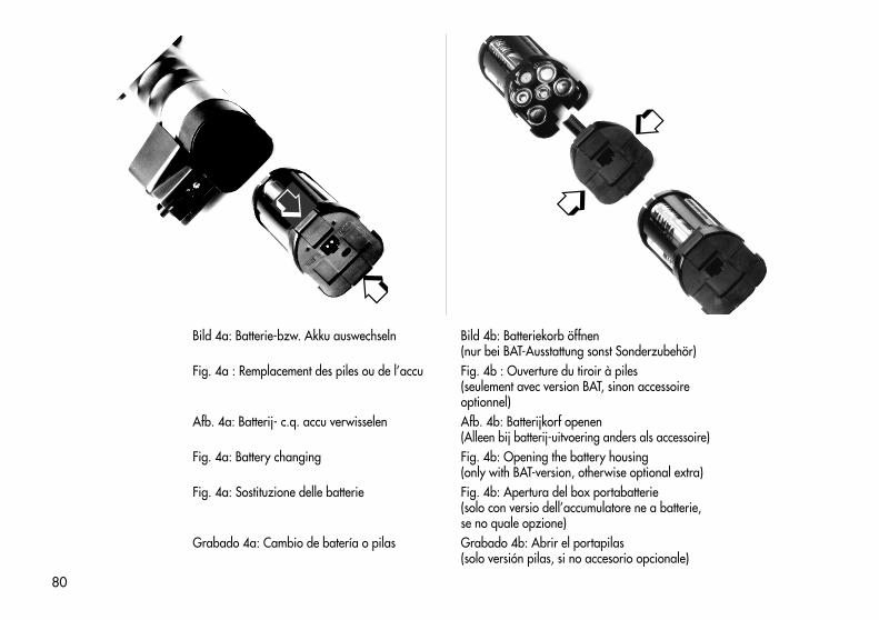
2.3 Battery replacementPress the two locking keys of the battery housing, and pull out of the flashgun(fig. 4a). To return the battery housing press the two locking keys togetherand press into the handle-mount grip of the flashgun until it audibly engages.
2.3.1 Exchanging the batteriesPress together the smooth locking keys of the dismantled battery housing(only with BAT-version, otherwise optional extra) and remove the lid (fig. 4b).Insert new batteries in conformity with the polarity symbols indicated in thebase of the housing. Return the lid and lock in again.
Spent batteries must not be thrown into the domestic waste! Help keepthe environment clean and discard spent batteries at correspondingcollecting points!
The battery housing must not be fitted with NiCad batteries! The contactsof the battery housing are only intended for alkaline manganese batte-ries. The lower resistance of NiCad batteries means that more current canflow, and this can damage the flashgun. The NiCad Battery Pack 45-40has special contacts which do not allow the flow of high currents.
2.3.2 Operation with the battery packThe NiCad battery should be charged for 5 hours before it is used for the firsttime. The NiCad battery can be charged within the flashgun or externally.
Warning: The flashgun must NOT be switched on while the battery isbeing charged within the flashgun!
The NiCad battery is discharged if the recycle time after a flash exceeds 60seconds.Adjust the correct mains voltage on the charger prior to charging. The volta-ge selector (fig. 5a) is located next to the plug and can be adjusted with asmall screwdriver.The connection for the charger (fig. 5b) is in the base of the NiCad battery.
�
�
�
The adjoining pilot lamp lights up while charging is in progress.The charging time for a completely exhausted NiCad battery is 5 hours. Apartly discharged NiCad battery requires a correspondingly diminishedcharging time.• To identify an exhausted battery: Push the knurled slide in the battery lid to
the black mark.• To identify a charged battery: Push the knurled slide in the battery lid to the
white mark.
2.4 Switching the flashgun on and offThe flashgun is switched on with the main switch �. The flashgun is perma-nently switched on when the switch is pushed to the top position, and theoperating light shines. Push the main switch to the bottom position to switchoff the flashgun.
3. TTL Flash Mode(only with SCA adapter)
Perfect flash exposures can be shot in a simple manner in TTL mode.The exposure readings in TTL mode are made by the sensor built into thecamera. This sensor measures the light reaching the film through the cameralens. As soon as the film has been exposed by the correct amount of light, anelectronic control circuit within the camera transmits a stop signal to theadapter (optional accessory), and the flash is instantly cut out.The advantage of this flash mode is that all factors influencing the exposureof the film (filters, change of aperture and focal length with zoom lenses,extensions for close-ups, etc.) are automatically taken into account.
The TTL flash mode is only possible with cameras that feature this func-tion. The flashgun must be fitted with a corresponding SCA adapter(see SCA 3002 System Instructions and SCA Survey Table) for this pur-pose. A film must be loaded in the camera to test the TTL functions.
Exposure corrections may be necessary with pronounced differencesin contrast, for instance dark objects in snow (see Ch. 11, page 49).
�
�

45
�
Adjusting procedure for TTL flash mode:• Adjust the camera according to the manufacturer’s operating instructions.• Turn the adjusting knob for film speed � until the white marker is positio-
ned opposite the ISO film speed so that the distance range can be read off.The film speed must also be set on the camera and, if necessary, on theSCA adapter.
• Fit the flashgun with the appropriate SCA adapter and mount on thecamera.
• Switch on the flashgun with the main switch �.• Turn the selector dial to TTL.
The distance ranges can be directly read off the aperture calculator, ortaken from Table 3, page 77 .
To check the range, the flash can only be fired by the camera and notby way of the manual firing botton on the flashgun (where possiblethe camera should be adjustet to multiple exposure.
4. Automatik Flash ModeIn the automatic flash mode the photosensor measures the light reflected fromthe subject. The flash is cut off as soon as sufficient light has been emitted forcorrect exposure.In this manner there is no need to calculate and set a new aperture when thedistance is changed, provided that the subject remains within the indicatedautomatic flash range.The photosensor of the flashgun must be directed at the subject, regardless ofthe direction at which the main reflector is pointing. The photosensor has ameasuring angle of approx. 25°, and it only measures the actual amount oflight emitted by the flashgun.Six working apertures are available in the automatic flash mode.
�
Adjusting procedure for the automatic flash mode:Example:Flash-to-subject distance: 5 mFilm speed: ISO 100/21°• Adjust the camera according to the manufacturer’s operating instructions.• Turn the adjusting knob for film speed � until the white marker is positio-
ned opposite the ISO film speed.Under due consideration of the maximum flash range, a distance of 5 mpermits selection of the auto apertures f/8, f/5.6, f/4 and f/2.8.
• Switch on the flashgun with the main switch �.• Set the selector dial to one of the green identified auto apertures. The set-
ting line assigns the adjusted f-stop with the corresponding maximum flashrange on the distance scale. The minimum flash-to-subject distance isapprox. 10% of the maximum flash range.
• Adjust the same aperture on the flashgun and the camera.To achieve the shortest possible depth-of-field (as required in portraiture)we recommend an aperture of f/2.8. For group shots where there can beseveral rows of people behind each other, we recommend an aperture off/8.
• Wait for flash readiness - the green LED lights up.The subject should be within the middle third of the distance range.This gives the electronic control sufficient scope for compensationshould this be necessary.
There is a certain measure of overlap between the individual automatic aper-tures. As a result of this overlap it is always possible to place the subject wit-hin the middle third of the range.
CAUTION with zoom lenses!Due to their design they can cause a loss of light in the order of up toone f-stop. Furthermore, the effective aperture can also vary, depen-ding upon the adjusted focal length. This must be compensated bymanually correcting the aperture setting on the flashgun!
�
�

46
�
5. Manual Flash ModeIn this mode the flashgun will emit its full power, provided that partial lightoutput (M1/2 - M1/4) has not been adjusted. The flashgun can be adaptedto the actual picture shooting situation by setting the corresponding apertureon the camera.If the displayed value does not coincide with the actual distance, then theaperture and/or partial light output level (M1/2 and M 1/4) have to bechanged accordingly.The decisive points for partial light output are:• The distance to the subject• The required aperture• The ISO film speedAdjusting procedure for the manual flash mode:Example:Flash-to-subject distance: 5 mFilm speed: ISO 100/21°• Adjust the camera according to the manufacturer’s operating instructions.• Turn the adjusting knob for film speed � until the white marker is positio-
ned opposite the ISO film speed.• Switch on the flashgun with the main switch �.• Set the selector dial to M.
The aperture to be adjusted is indicated on the scale above the given flash-to-subject distance.
At a flash-to-subject distance of 5 m (as in our example), an apertureof f/8 has to be set on the camera. The adjusted aperture must be cor-rected when the wide-angle diffuser is used. The settings calculatortakes the wide-angle diffuser into account.
�
6. Bounced FlashPhotos shot with full frontal flash are easily recognizable by their harsh, den-se shadows. This is often associated with a sharp drop of light from the fore-ground to the background.This phenomenon can be avoided with bounced flash because the diffusedlight will produce a soft and uniform rendition of both the subject and thebackground. For this purpose the main reflector is turned in such a mannerthat the flash is bounced back from a suitable reflective surface (e.g. ceilingor walls of a room).For this reason the main reflector can be turned vertically and horizontally.The following are the vertical lock-in positions for bounced flash:• 15°, 30°, 45°, 60°, 75° and 90° (simply tilt the reflector to the required
angle)The head can be swivelled horizontally to the left and right by 180°, andlocks into position at 90° and 180°.
When swivelling the reflector vertically, it is essential to ensure that itis turned by a sufficiently wide angle so that direct light can no longerfall on the subject. Therefore, always tilt the reflector to at least the 60°lock-in position.
The diffused light bounced back from the reflective surfaces results in a softillumination of the subject.The reflecting surface must be white or a neutral colour, and it must not bestructured (e.g. wooden beams in the ceiling) as this could cast shadows. Forcolour effects just select reflective surfaces in the required colour.Use of the secondary reflector is advantageous to avoid disturbing denseshadows with bounced flash, for instance under the eyes and nose of por-traits.
6.1 Bounced flash with activated secondary reflectorThe secondary reflector � produces frontal fill-in light when the flash isbounced.
�

47
�
The use of the secondary reflector is only expedient with bouncedflash.
Switch turns the secondary reflector � on and off.When the secondary reflector is activated, 85% of the light will be emitted bythe main reflector, and approx. 15% by the secondary reflector. The quotedpercentages may vary somewhat when flash with partial light output is adju-sted, and the secondary reflector switched on.Light output can be reduced with a light reducing filter by approx. 40%. Forthis purpose place the reducing filter over the secondary reflector and pressboth sides firmly until the filter audibly clicks into position.
6.2 Bounced flash in automatic and TTL flash modesIt is advisable to check prior to the actual exposure whether the light is suffi-cient for the selected aperture. Please refer to Ch. 9, page 48, for the corre-sponding procedure.
6.3 Bounced flash in manual flash modeThe required camera aperture in the manual flash mode is best establishedwith an exposure meter. Observe the following rule of thumb if an exposuremeter is not available
guide numberCamera aperture = —————————
light distance x 2
to establish the guide value for the aperture that can then be varied by +1 f-stop for the actual exposure.
� 7. Winder ModeDefinition:The winder mode involves shooting a sequence of pictures at a rate of severalframes per second. The winder mode uses partial light output levels (M 1/40).Up to 2 flashes per second can be fired in this mode.Adjusting procedure to work in winder flash mode• Adjust the camera according to the manufacturer’s operating instructions.• Turn the adjusting knob for film speed � until the white marker is positio-
ned opposite the ISO film speed.• Switch on the flashgun with the main switch �.• Set the selector dial to W.• Wait for flash readiness � - the green LED lights up.The aperture to be set on the camera can be read off the scale, opposite theflash-to-subject distance.
Winder mode is only possible with a NiCad battery or Power Pack.
8. Fill-in Flash in DaylightThe mecablitz can also be used for fill-in flash in daylight to soften harsh sha-dows and lower the contrast, thereby producing a more balanced exposurewhen shooting against the light. Various possibilities are open to the user forthis purpose.
8.1 Fill-in flash in automatic modeUse the camera, or a hand-held exposure meter, to establish the requiredaperture and shutter speed for a normal exposure. Ensure that the shutterspeed either equals, or is slower than, the fastest flash synch speed (varieswith the given camera model).Example:Established aperture = f/8; established shutter speed = 1/60 sec. Flashsynch speed of the camera, e.g. 1/100 sec. (see operating instructions for
�
48
�
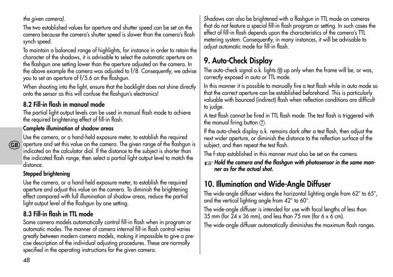
the given camera).The two established values for aperture and shutter speed can be set on thecamera because the camera’s shutter speed is slower than the camera’s flashsynch speed.To maintain a balanced range of highlights, for instance in order to retain thecharacter of the shadows, it is advisable to select the automatic aperture onthe flashgun one setting lower than the aperture adjusted on the camera. Inthe above example the camera was adjusted to f/8. Consequently, we adviseyou to set an aperture of f/5.6 on the flashgun.When shooting into the light, ensure that the backlight does not shine directlyonto the sensor as this will confuse the flashgun’s electronics!
8.2 Fill-in flash in manual modeThe partial light output levels can be used in manual flash mode to achievethe required brightening effect of fill-in flash.Complete illumination of shadow areasUse the camera, or a hand-held exposure meter, to establish the requiredaperture and set this value on the camera. The given range of the flashgun isindicated on the calculator dial. If the distance to the subject is shorter thanthe indicated flash range, then select a partial light output level to match thedistance.Stepped brighteningUse the camera, or a hand-held exposure meter, to establish the requiredaperture and adjust this value on the camera. To diminish the brighteningeffect compared with full illumination of shadow areas, reduce the partiallight output level of the flashgun by one setting.
8.3 Fill-in flash in TTL modeSome camera models automatically control fill-in flash when in program orautomatic modes. The manner of camera internal fill-in flash control variesgreatly between modern camera models, making it impossible to give a pre-cise description of the individual adjusting procedures. These are normallyspecified in the operating instructions for the given camera.
Shadows can also be brightened with a flashgun in TTL mode on camerasthat do not feature a special fill-in flash program or setting. In such cases theeffect of fill-in flash depends upon the characteristics of the camera’s TTLmetering system. Consequently, in many instances, it will be advisable toadjust automatic mode for fill-in flash.
9. Auto-Check DisplayThe auto-check signal o.k. lights up only when the frame will be, or was,correctly exposed in auto or TTL mode.In this manner it is possible to manually fire a test flash while in auto mode sothat the correct aperture can be established beforehand. This is particularlyvaluable with bounced (indirect) flash when reflection conditions are difficultto judge.A test flash cannot be fired in TTL flash mode. The test flash is triggered withthe manual firing button .If the auto-check display o.k. remains dark after a test flash, then adjust thenext wider aperture, or diminish the distance to the reflection surface of thesubject, and then repeat the test flash.The f-stop established in this manner must also be set on the camera.
Hold the camera and the flashgun with photosensor in the same man-ner as for the actual shot.
10. Illumination and Wide-Angle DiffuserThe wide-angle diffuser widens the horizontal lighting angle from 62° to 65°,and the vertical lighting angle from 42° to 60°.The wide-angle diffuser is intended for use with focal lengths of less than35 mm (for 24 x 36 mm), and less than 75 mm (for 6 x 6 cm).The wide-angle diffuser automatically diminishes the maximum flash ranges.
�

49
�
11. Exposure CorrectionsThe automatic exposure systems are based on a subject reflection factor of25%, this being the average reflection factor for subjects shot with flash.Dark backgrounds absorb a lot of light, while bright backgrounds reflect agreat deal of light (e.g. backlit scenes), thereby resulting in subject overexpo-sure or underexposure, respectively.
11.1 Exposure correction in automatic flash modeTo compensate the above mentioned effect, the exposure can be corrected byopening or stopping down the camera’s aperture. With a bright backgroundthe sensor of the flashgun cuts out the flash too soon with the result that theactual subject is too dark. With a dark background the flash is cut out toolate so that the actual subject is too bright.
Bright background:Open the camera aperture by 1/2 to 1 f-stop (e.g. from f/5.6 to f/4).
Dark background:Close the aperture by 1/2 to 1 f-stop (e.g. from f/8 to f/11).
11.2 Exposure correction in TTL flash modeMany cameras feature an adjusting element for exposure corrections thatcan also be used in TTL flash mode.Please observe the corresponding explanations in the Operating Instructionsfor the camera.Here, exposure correction by changing the aperture on the lens is not possi-ble. This is because the camera’s automatic exposure system will regard thechanged f–stop as a normal working aperture.
�
�
12. Care and MaintenanceRemove dust and grime with a soft dry cloth, or a silicon-treated cloth. Donot use detergents as these may damage the plastic parts.Forming the flash capacitorThe flash capacitor incorporated in the flashgun undergoes a physical chan-ge when the flashgun is not switched on for prolonged periods. For this rea-son it is necessary to switch on the flashgun for approx. 10 minutes every 3months. The battery must supply sufficient power to light up the flash-readylight within one minute after the flashgun was switched on.
13. Technical DataGuide numbers at ISO 100/21°:For meter systems: 45; for feet systems: 1486 auto working apertures at ISO 100/21°:f/2.8 - f/4 - f/5.6 - f/8 - f/11 - f/16Flash durations:• approx. 1/300...1/20000 second• In M mode approx. 1/300 second at full light output• At 1/2 light output approx. 1/1000 second• At 1/4 light output approx. 1/2500 second• In winder mode approx. 1/10000 secondPhotosensor measuring angle: approx. 25°Colour temperature: approx. 5600 KFilm speed: ISO 25 to ISO 1000Synchronization: Low-voltage thyristor ignitionNumber of flashes: 50*...2000 NiCad battery100*...2600 with alkaline-manganese batteries140*...3600 with high-capacity alkaline-manganese batteries
(*with full light output)

50
�
Recycling time:7 sec. (in M mode)...0.3 with NiCad battery13 sec. (in M mode)...0.3 sec. with alkaline-manganese batteries11 sec. (in M mode)...0.3 sec. with high-capacity alkaline-manganese batteriesSwivelling range and locking positions of zoom reflector:Upwards: 15° 30° 45° 60° 75° 90°Anti-clockwise 90° 180°Clockwise 90° 180°Dimensions (w x h x d), approx.Flashgun 92 x 247 x 102 mmWeight:Flashgun without power sources: approx. 680 gTable 1: Guide numbers at maximum light output (Pag. 76)Table 2: Chargers (Pag. 76)Table3: Distances in TTL flash mode (Pag. 77)
3. . . 16 Distance range without wide-angle diffuser2. . . 11 Distance range with wide-angle diffuser
These zable does not apply to bounced flash.Included:Flashgun, camera bracket, battery housing 45-39 (only with BAT-version,otherwise optional extra), synch cable 45-47, wide-angle diffuser 45-42,light reducing filter 45-44, Operating Instructions, SCA 300/3002 Table,(additionally with NiCad flashguns: NiCad battery pack 45-40 and batterycharger, see table 2, page 76).
14. Optional accessoriesMalfunctions and damage caused to the mecablitz due to the use ofaccessories from other manufacturers are not covered by our guaran-tee!
• Adapter of the System SCA 300.For flash with system cameras (see separate operating instructions). TheSCA 300 A connecting cable is additionally required.
• Adapter of the System SCA 3002For flash with system cameras with digital data transmission of the SCAfunction. Extended functional features compared with the SCA 300 System(see separate Operating Instructions). The SCA 3000 C connecting cable isadditionally required.
• Bag 45-29 (Order No: 0004529) for telephoto attachment 45-33.
• Battery holder 45-39For alkaline manganese batteries.
• Battery charger set B 45 (Order No: 0012045)NiCad battery and charger for subsequent conversion of the 45 CL-4Battery model to NiCad battery operation.
• Bounce diffuser 60-33 (Order No: 0006033)To soften heavy shadows with reflected light.
• Bracket adapter 45-35 (Order No: 004535)For parallax correction of reflector and camera with close-ups and wide-angle shots.
• Bracket adapter 60-28 (Order No: 0006028)Similar to 45-35, except adjustable in height.
• Camera bracket 70-35 (Order No: 0007035)To attach the flashgun to the side of the camera.
• Camera cable release 45-26 (Order No: 0004526)The camera shutter can be tripped with the same hand that is holding theflashgun. This frees the other hand for focusing.
�
51
�
• Electric shutter release 45-25 (Order No: 0004525)As 45-26, except with switch for electric actuation.
• Ever-ready case 45-34 (Order No: 0004534)for flashgun and accessories.
• Filter set 45-32 (Order No: 0004532)Consists of a set of 4 colour effects filters and 1 clear filter to hold anycoloured foil.
• Light reducing filter set 45-28 (Order No: 0004528Consists of three neutral density filters, and a transparent filter holder forcoloured foils.
• Mecalux 11 (Order No: 0000011)Slave triggering unit. For optical, delay-free remote triggering of slaveflashguns by a camera-triggered flash. Responds also to infrared lightbeam. Does not require batteries.
• Mecalux Holder 60-26 (Order No: 0006026)To mount the Mecalux 11.
• Mecamat 45-46 (Order No: 0004546)External sensor that significantly extends the application range of themecablitz. 11 auto apertures are available. „MANUAL“ provides 7 co-ordinated light output levels with 7 fixed flash durations. Built-in viewfinderwith parallax compensation for close-ups. Two measuring angles of 25°and 12° for optimal measurement.
• NiCad battery pack 45-40 (Order No: 0004540)• Power Pack P 50 (Order No: 0012950)
For a high number of flashes and short recycling times (approx. 300 full-power flashes)
• Shoulder strap 50-31 (Order No: 0005031)• Stabilizing set 30-28 (Order No: 0003028)
Ensures that the camera cannot be inadvertently turned on the bracket.• Standard foot 301 (Order No: 0093014)
Used in conjunction with SCA 300 A for connection to camera hot shoe.
• Synch lead SCA 300 A (Order No: 0009305)Cable to connect the flashgun to the adapter of the SCA 300 System.
• Synch lead SCA 3000 C (Order No: 0033003)Cable to connect the flashgun to the adapter of the SCA 3000 System.
• Synch leads:Coiled synch lead 45-49 (Order No: 0004549)Coiled synch lead 45-54 for hot shoe (Order No: 0004554)Synch lead 45-48, 1 m (Order No: 0004548)Synch extension lead 60-53 (1.25 m) (Order No: 0006053)Synch extension lead 60-54 (5 m) (Order No: 0006054)
• Telephoto attachment 45-33 (Order No: 0004533)For flash shots with telelenses. Nearly doubles the guide number. Infraredshots are also possible.

76
�
�
�
�
�
�
ISOLeitzahl, No-guide, Richtgetal
Guide number, Numero guida, N°-Guia
[m]
23252832364045505764718090101113127142
[ft]
748393105118132148166186209235263295331372417468
25/15°32/16°40/17°50/18°64/19°80/20°100/21°125/22°160/23°200/24°250/25°320/26°400/27°500/28°650/29°800/30°1000/31°
Tabelle 1: Leitzahlen bei maximaler LichtleistungTableau 1: Nombres-guides pour niveau de puissance maximalTabel 1: Richtgetallen bij vol vermogenTable 1: Guide numbers at maximum light outputTabella 1: Numeri guida a potenza pienaTabla 1: Número-guía con plena potencia de luz
Land, Pays, CountryPaese, País
Ladegerät, chargeur, Laadapparaten,charger, ricaricatore, cargador
729723728722730
402.12e725726
EuropeGreat Britain
USA / CanadaAustralia
JapanSouth AfricaNew Zealand
Korea
Tabelle 2: LadegeräteTableau 2: ChargeursTabel 2: LaadapparatenTable 2: ChargersTabella 2: apparecchi di ricaricaTable 2: Cargadores

77
�
�
�
�
�
�
1,4
2
2,8
4
5,6
8
11
16
22
32
3......162......112......111,5...81,5...81......61......60,7...40,7...40,5...30,5...30,4...2
------
4......233......163......162......112......111,5...81,5...81......61......60,7...40,7...40,5...30,5...30,4...20,4...20,3...1,5
----
5......324......234......233......163......162......112......111,5...81,5...81......61......60,7...40,7...40,5...30,5...30,4...20,4...20,3...1,5
--
--
5......324......234......233......163......162......112......111,5...81,5...81......61......60,7...40,7...40,5...30,5...30,4...20,4...20,3...1,5
----
5......324......234......233......163......162......112......111,5...81,5...81......61......60,7...40,7...40,5...30,5...30,4...2
------
5......324......234......233......163......162......112......111,5...81,5...81......61......60,7...40,7...40,5...3
25/15° 50/18° 100/21° 200/24° 400/27° 800/30°
Kam
era
-Ble
nde
/ O
uver
ture
de
l’app
arei
l / c
amer
a-di
afra
gma
Cam
era
aper
ture
/ D
iafra
mm
a de
lla fo
toca
mer
a /
Diaf
ragm
a de
la cá
mar
a
I S O
Entfernungsbereich / Portée / Flitsbereiken [m]Distance range / Campo di utilizzo / Gama de distancias [m]
0,4...20,3...1,5
Tabelle 3: EntfernungsbereichTableau 3: PortéeTabel 3: FlitsbereikenTable 3: Distance rangeTabella 3: Campo di utilizzoTable 3: Gama de distancias

78
�
�
�
�
�
Bild 1Fig. 1Afb. 1Grab. 1
Bild 2Fig. 2Afb. 2Grab. 2
�
�
�
�

79
� Reflektor / Réflecteur / Reflector / Riflettore
� Sensor / Sensore
� Schienenhalter / Support de barrette / Beugelhouder, Bracket holder / Supporto staffa / Porta-regleta
� Haltebock / Bloc d’attache / Vastzetblok / Holder block / Blocco reggi-staffa / Zapata de sujeción
Anschluß Power Pack / Prise pour Power Pack / Aansluiting Power Pack /Power Pack connection / Presa per Power Pack / Conexión Power Pack
� Synchronlkabelbuchse / Prise du cáble synchro / Aansluiting voorflitskabel / Sync cord socket / Presa per cavetto sincro / Conexiónpara cable sincro
� Schalter für Zweitreflektor / Interrupteur réflecteur secondaire /Schakelaar tweede reflector / Switch for secondary reflector /Interruttore parabola ausiliaria / Interruptor reflector adicional
Blitzbereitschaftsanzeige / Témoin de fonctionnament /Flitsparaataan-duiding / Flash range indicator / Indicazione pron-to lampo / Indicador de disposición
�
Belichtungskontrollanzeige / Témoin de contrôle d’exposition /Aanduiding van de belichtingscontrol / Exposure o.k. /Indicazione di controllo esposizione / Indicación de control de laexposición
�
Handauslösetaste / Bouton d’open-flash / Ontspanknop voor handbedie-ning / Manual firing button / Scatto sincro manuale / Disparador manual
Zweitreflektor / Réflecteur secondaire / Tweede reflector /Secondary reflector / Parabola ausiliaria / Reflector adicional
� Einstellknopf für Filmempfindlichkeit / Clef de réglage de la sensi-bilité / Instelknop voor filmvoeligheid / Film speed setting knob /Pomello d’impostazione della sensibilità / Botón de ajuste de lasensibilidad de película
� Einstellmarke für Blendenvorwahl / Repère de réglage carré pourla présélection du diaphragme / Instelmarkering voor diafragma-voorkeuze / Frame for preselection of aperture, Indice quadratoper preselezionare i diaframmi / Indice para la preselección dediafragma
�
Hauptschalter / Interrupteur général / Hoofdschakelaar / Mainswitch / Interruttore principale / Interruptor principal �
�
Bild 3Fig. 3Afb. 3Grab. 3
80
Bild 4a: Batterie-bzw. Akku auswechseln Bild 4b: Batteriekorb öffnen(nur bei BAT-Ausstattung sonst Sonderzubehör)
Fig. 4a : Remplacement des piles ou de l’accu Fig. 4b : Ouverture du tiroir à piles(seulement avec version BAT, sinon accessoire optionnel)
Afb. 4a: Batterij- c.q. accu verwisselen Afb. 4b: Batterijkorf openen(Alleen bij batterij-uitvoering anders als accessoire)
Fig. 4a: Battery changing Fig. 4b: Opening the battery housing(only with BAT-version, otherwise optional extra)
Fig. 4a: Sostituzione delle batterie Fig. 4b: Apertura del box portabatterie (solo con versio dell’accumulatore ne a batterie, se no quale opzione)
Grabado 4a: Cambio de batería o pilas Grabado 4b: Abrir el portapilas(solo versión pilas, si no accesorio opcionale)
➭
➭
➭
➭

81
Bild 5a: Spannungswähler Bild 5b: Akku ladenFig. 5a : Sélecteur de tension Fig. 5b : Charge de l’accuAfb. 5a: Spanningskiezer Afb. 5b: Accu opladenFig. 5a: Voltage selector Fig. 5b: Charging the batteryFig. 5a: Selettore di tensione Fig. 5b: Carica dell’accumulatoreGrabado 5a: Selector de tensión Grabado 5b: Carga de la batería

Atención:El símbolo CE significa una valoraci-ón dae exposición correcta con laprueba EMV (prueba de toleranciaelectromagnética).
No tocar los contactos SCA !
En algunos casos un contacto pue-de producir daños en el aparato.
Avvertenza:Nell’ambito delle prove EMV per ilsegno CE è stata valutata la correttaesposizione.
Non toccate mai i contatti SCA !
In casi eccezionali il toccare puòcausare danni all’apparecchio.
�
�Opmerking:In het kader de CE-markering werdbij de EMV-test de correcte be-lich-ting bepaald.
SCA Contacten niet aanraken !
In uitzonderlijke gevallen kan aanra-ken leiden.
�
Remarque:L’exposition correcte a été évaluéelors des essais de CEM dans lecadre de la certification CE.
Ne pas toucher les contacts duSCA !
Il paut arriver que le contact avecles doigts provoque la dégradationde l’appareil.
�
Hinweis:Im Rahmen des CE-Zeichens wurdebei der EMV-Prüfung die korrekteBelichtung ausgewertet.
SCA-Kontakte nicht berühren !
In Ausnahmefällen kann eine Berüh-rung zur Beschädigung des Gerätesführen.
� Note:Within the framework of the CE ap-proval symbol, correct exposure wasevaluated in the course of the electro-magnetic compatibility test.
Do not touch the SCA contacts !
In exceptional cases the unit can bedamaged if these contacts are touched.
�

703 47 0149.A2
� � � � � �
Metz - Werke GmbH & Co KG • Postfach 1267 • D-90506 Zirndorf • [email protected] • www.metz.de
Consumer electronics Photoelectronics Plastics technology Industrial electronics
Metz. Always first class.