mechanical effects of short-circuit currents analysis on ...pe.org.pl/articles/2011/7/62.pdf ·...
TRANSCRIPT
272 PRZEGLĄD ELEKTROTECHNICZNY (Electrical Review), ISSN 0033-2097, R. 87 NR 7/2011
1Miroslav GUTTEN, Jozef JURČIK, Martin BRANDT, Radek POLANSKY 1University of Žilina, Slovakia, 2ZČU Plzeň, Czech republic
Mechanical effects of short-circuit currents analysis on autotransformer windings
Abstract. This article deals with a description of methods of an experimental analysis (SFRA method, monitoring, thermovision) concerning the actual reliability of windings and magnetic circuit of the transformer, which is required in power transmission and power distribution companies all over the world. Streszczenie. Artykuł opisuje eksperymentalną analizę badania niezawodności uzwojeń i obwodu magnetycznego transformatora mocy. (Analiza efektów mechanicznych przy występowaniu zwarcia w uzwojeniu autotransformatora) Keywords: Transformer, diagnostics, SFRA method, monitoring, thermovision. Słowa kluczowe: diagnostyka transformatora, termowizja. Introduction
The short circuits in operation are commonly created by different line faults, etc. in mechanical damage of insulation, an electric insulation, an electric insulation breakdown on over voltage, wrong operation and in the next case row.
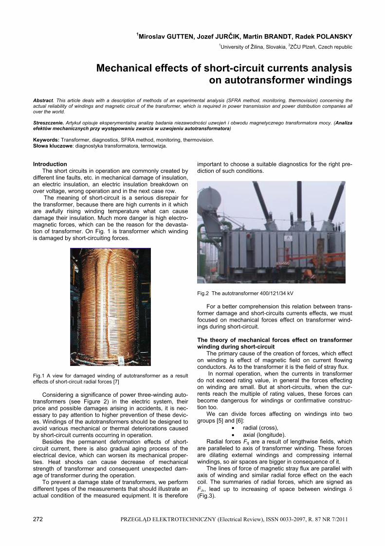
The meaning of short-circuit is a serious disrepair for the transformer, because there are high currents in it which are awfully rising winding temperature what can cause damage their insulation. Much more danger is high electro-magnetic forces, which can be the reason for the devasta-tion of transformer. On Fig. 1 is transformer which winding is damaged by short-circuiting forces.
Fig.1 A view for damaged winding of autotransformer as a result effects of short-circuit radial forces [7]
Considering a significance of power three-winding auto-
transformers (see Figure 2) in the electric system, their price and possible damages arising in accidents, it is nec-essary to pay attention to higher prevention of these devic-es. Windings of the autotransformers should be designed to avoid various mechanical or thermal deteriorations caused by short-circuit currents occurring in operation.
Besides the permanent deformation effects of short-circuit current, there is also gradual aging process of the electrical device, which can worsen its mechanical proper-ties. Heat shocks can cause decrease of mechanical strength of transformer and consequent unexpected dam-age of transformer during the operation.
To prevent a damage state of transformers, we perform different types of the measurements that should illustrate an actual condition of the measured equipment. It is therefore
important to choose a suitable diagnostics for the right pre-diction of such conditions.
Fig.2 The autotransformer 400/121/34 kV For a better comprehension this relation between trans-
former damage and short-circuits currents effects, we must focused on mechanical forces effect on transformer wind-ings during short-circuit.
The theory of mechanical forces effect on transformer winding during short-circuit
The primary cause of the creation of forces, which effect on winding is effect of magnetic field on current flowing conductors. As to the transformer it is the field of stray flux.
In normal operation, when the currents in transformer do not exceed rating value, in general the forces effecting on winding are small. But at short-circuits, when the cur-rents reach the multiple of rating values, these forces can become dangerous for windings or confirmative construc-tion too.
We can divide forces affecting on windings into two groups [5] and [6]:
radial (cross), axial (longitude).
Radial forces Fq are a result of lengthwise fields, which are paralleled to axis of transformer winding. These forces are dilating external windings and compressing internal windings, so air spaces are bigger in consequence of it.
The lines of force of magnetic stray flux are parallel with axis of winding and similar radial force effect on the each coil. The summaries of radial forces, which are signed as F,, lead up to increasing of space between windings (Fig.3).

PRZEGLĄD ELEKTROTECHNICZNY (Electrical Review), ISSN 0033-2097, R. 87 NR 7/2011 273
Infinite small change of magnetic field energy adequate infinite small rising space [5]
(1) Fw , from
w
F
Magnetic fields energy:
(2) zXfiw
2
1
2
1 2
where: i – current momentary value at windings, Xz – leak-age reactance in short of the windings, f – frequency,
so, force formula is:
(3)
w
F = 72 10)(2 u
str
L
lit
where: (it) – coil ampere-turn, lstr – average winding length in, Lu is height of winding.
Fig.3 Radial forces Fq effect on transformer windings
The axial forces rise from the center to border of wind-
ing, where the magnetic field has the biggest cross compo-nent. In short-circuits axial forces can reach dangerous, so they can deform outer coil too.
As to asymmetric windings axial forces are dangerous. The forces which are created by a small displacement of both coils, try to make this displacement bigger. This dis-placement can be created by coils which are not totally similar. The asymmetry can be also created by insulation of high voltage coil because there are more insulators than in the lower voltage coil winding. But there is a possibility of retract any side of insulation in the totally similar coils. This retract can by caused by drying-out.
According to [2] we need to pay more attention to catch-ing outer coil. In case of released coil, the axial forces Fd (Figure 4) can cause displacement of outer coils to the vertical sides (on Figure 4 is origination of empty spaces). The redundant pressure on spacers can press insulation and moved winding, what can cause seriously damages of transformer.
Fig.4. The pressurize the coil conductors by excessive effect of axial forces pressing (influence on the deformation of insulation)
On Figure 5 illustrates pitching of coil conductors by ac-tion of the excessive axial forces (effect to insulation com-pression).
Fig.5. Pitching of coil conductors by action of the excessive axial forces.
Theory of SFRA method and its importance in trans-former diagnostics
SFRA method belongs to current most effective anal-yses and allows to detect the influences of short-circuit currents, overcurrents and other effects damaging either winding or magnetic circuit of the transformer. This all can be performed without a necessity of decomposition of de-vice and subsequent winding damage determination, which is very time consuming.
The method of the high-frequency analysis (Sweep Fre-quency Response Analyzer – SFRA [3]) is also one of the methods of undisassembling diagnostics of transformers. No intervention to the construction of tested device is de-manded, the whole measurement is performed on detached device (not under the voltage). This method is applicable mainly for determination and measuring immediately after the manufacturing of device, i.e. for measuring of reference values. These parameters are consequently compared to the other measurements performed on the transformer, which is decommissioned, after the damages or revisions of transformer etc.
There is possible to detect by SFRA: a deformation of winding and its movements, a short-circuited turn or opened winding, a loose switching system, a damaged switching system, a core connection problem a partial breakdown of winding, a core movement or its wrong grounding.
Results measured on the new transformer can be used as the reference parameters for further comparison with values measured later after certain operation time of the transformer. They can be also compared with the test re-sults performed after the transformer breakdown (or after the n-short-circuits) or repair or it can be used as a diagnos-tic test, when vibration sensors indicate some potential problem in transformer.
SFRA as a one of the most predictable methods is based on functional high-frequency generator and spectral recording analyzer principle, which are set up and con-trolled by computer. This method is used also by M5100 measuring system (see Fig.6) constructed by American DOBLE company [3].
According to [1] SFRA method determines the trans-former responses in a time or frequency area. The time response measurement provides curve determination of the time response to the specific voltage impulse applied to winding input connection. The frequency response meas-urement consists in determination of amplitude eventually
274 PRZEGLĄD ELEKTROTECHNICZNY (Electrical Review), ISSN 0033-2097, R. 87 NR 7/2011
phase response to the harmonic voltage of variable fre-quency applied to winding input. While the time response is the record of time behaviour of voltage, frequency response is the amplitude response dependence on frequency.
Fig.6. DOBLE M5100 measuring system A relation between the response and the winding condi-
tion is definite, otherwise it is complicated. It is impossible to expect the assessment of concrete damage of winding from differences in response behaviours. The measurement results lead us only to a statement of the fact that some change of winding condition really occurred. Such test re-sults are very helpful to decide, whether it is unavoidable to open and revise the transformer or not.
Measuring principles SFRA and experimental analysis of autotransformer
The behaviour of transformer winding response reflects e.g. electromagnetic couplings between the winding and transformer tank, also between the primary and secondary (eventually tertiary) winding, between the windings of par-ticular phases or between turns themselves of particular windings.
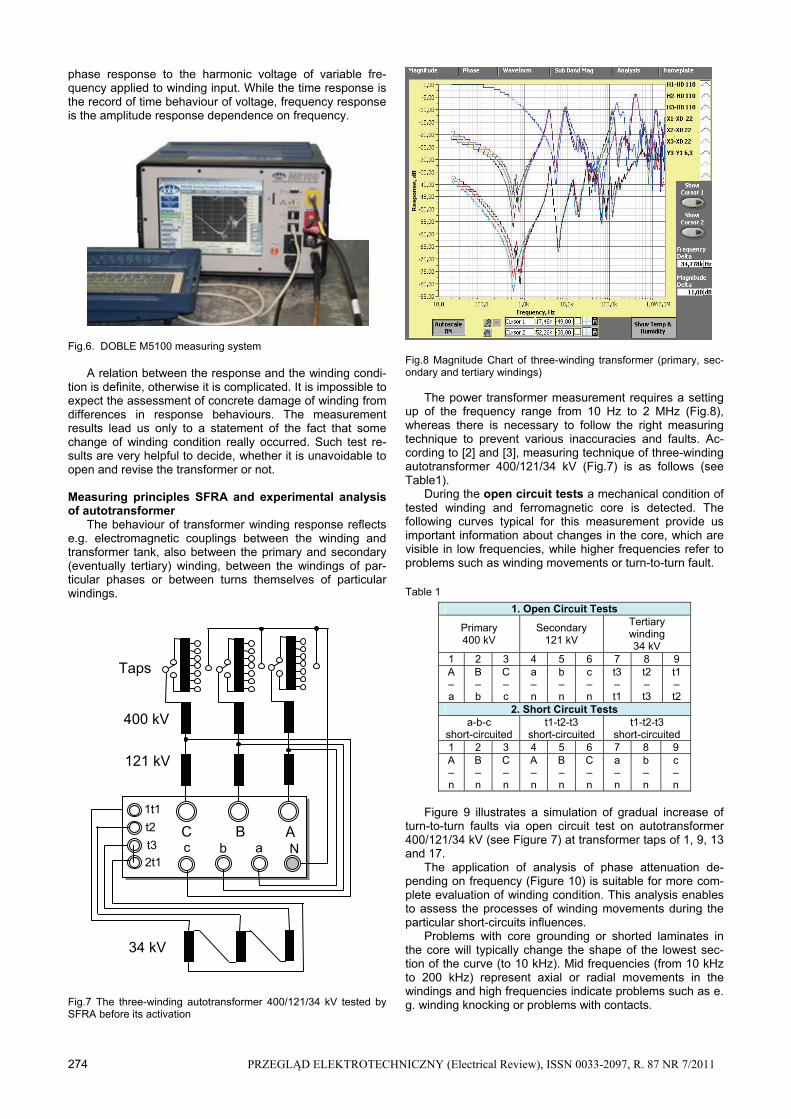
Fig.7 The three-winding autotransformer 400/121/34 kV tested by SFRA before its activation
Fig.8 Magnitude Chart of three-winding transformer (primary, sec-ondary and tertiary windings)
The power transformer measurement requires a setting up of the frequency range from 10 Hz to 2 MHz (Fig.8), whereas there is necessary to follow the right measuring technique to prevent various inaccuracies and faults. Ac-cording to [2] and [3], measuring technique of three-winding autotransformer 400/121/34 kV (Fig.7) is as follows (see Table1).
During the open circuit tests a mechanical condition of tested winding and ferromagnetic core is detected. The following curves typical for this measurement provide us important information about changes in the core, which are visible in low frequencies, while higher frequencies refer to problems such as winding movements or turn-to-turn fault.
Table 1
1. Open Circuit Tests
Primary 400 kV
Secondary 121 kV
Tertiary winding 34 kV
1 2 3 4 5 6 7 8 9 A –a
B – b
C – c
a – n
b – n
c – n
t3 – t1
t2 – t3
t1 – t2
2. Short Circuit Tests a-b-c
short-circuited t1-t2-t3
short-circuited t1-t2-t3
short-circuited 1 2 3 4 5 6 7 8 9 A – n
B – n
C – n
A – n
B – n
C – n
a – n
b – n
c – n
Figure 9 illustrates a simulation of gradual increase of
turn-to-turn faults via open circuit test on autotransformer 400/121/34 kV (see Figure 7) at transformer taps of 1, 9, 13 and 17.
The application of analysis of phase attenuation de-pending on frequency (Figure 10) is suitable for more com-plete evaluation of winding condition. This analysis enables to assess the processes of winding movements during the particular short-circuits influences.
Problems with core grounding or shorted laminates in the core will typically change the shape of the lowest sec-tion of the curve (to 10 kHz). Mid frequencies (from 10 kHz to 200 kHz) represent axial or radial movements in the windings and high frequencies indicate problems such as e. g. winding knocking or problems with contacts.
C B A c b a
1t1
2t1
t2
t3 N
Taps
400 kV
121 kV
34 kV
PRZEGLĄD ELEKTROTECHNICZNY (Electrical Review), ISSN 0033-2097, R. 87 NR 7/2011 275
Fig.9 Simulation of turn-to-turn fault increase by open circuit test on autotransformer at transformer taps of 1, 9, 13 and 17
Fig.10 Magnitude Chart of transformer secondary winding
During the short circuit tests only the winding condition in primary or secondary part of transformer is detected. This measurement notifies reliably of deformation of inner wind-ing and its movement as a result effects of short-circuit currents.
Conclusion
The state of the response depending up frequency is the image of geometrical winding movement and their construc-tion in transformer. The change of this state depends on thermal and mechanical effects of short circuit currents.
Problem of the frequency analysis of transformers by SFRA method is very comprehensive and its application becomes interesting for many transformer manufacturers and operators. From the long-term point of view the SFRA method is supposed to be very useful and it provides enough information on tested transformers. These trans-formers have their reference data obtained by the manufac-turers, suitable for the comparison with further data of par-ticular transformer.
SFRA testing method represents one of the most effec-tive alternative diagnostic methods compared to visual check. This method allows to detect the effects of the short-circuit currents, whereas we are able to evaluate the me-chanical strength action on the transformer winding during previous operation It is also possible to identify the specific winding phase, which has been mostly influenced by the short-circuit currents, without a necessity of transformer dividing, which would be very time consuming.
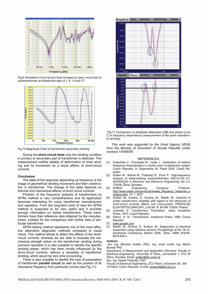
There is also possible to identify the size of parameters of transformer parallel circuit as well as the position of its resonance frequency from particular curves (see Fig.11).
Fig.11 Comparison of amplitude attenuation [dB] and phase curve [°] in frequency dependence (measurement of the same transform-er winding)
This work was supported by the Grant Agency VEGA from the Ministry of Education of Slovak Republic under contract 1/0548/09.
REFERENCES
[1] Kvasnička V., Procházka R., Velek J.: Verification of method frequency characteristics in control room of distribution system Czech Republic, In Diagnostika 05, Plzeň 2005, Czech Re-public
[2] Gutten M., Brandt M., Polanský R., Prosr P.: High-frequency analysis of three-winding autotransformers 400/121/34 kV, ADVANCES in Electrical and Electronic Engineering, No.1-2, 7/2008, Žilina, Slovakia
[3] DOBLE Engineering Company: Products: http://www.doble.com/products/sweep_frequency_response_analysis.html, 15. 1. 2007
[4] Gutten, M., Kučera, S., Kučera, M., Šebök, M.: Analysis of power transformers reliability with regard to the influences of short-circuit currents effects and overcurrents, PRZEGLĄD ELEKTROTECHNICZNY, p.62-64, R. 85 NR 7/2009, Poland
[5] Jezierski, E: Transformers. Theoretical basis, Academia Praha, 1973, Czech Republic
[6] Petrov, G. N.: Transformers, Academia Praha, 1980, Czech Republic
[7] www.google.com [8] Šebök, M., Kučera, S., Kučera, M.: Diagnostics of electrical
equipment using radiance sensors, Proceedings of the 7th In-ternational Conference Elektro 2008, Žilina, ISBN 978-80-8070-845-0
Authors: doc. Ing. Miroslav Gutten, PhD., Ing. Jozef Jurčík, Ing. Martin Brandt, PhD. Department of Measurement and Application Electrical, Faculty of Electrical Engineering, University of Žilina, Univerzitná 1, 010 26 Žilina, Slovakia, Email: [email protected] doc. Ing. Radek Polanský, PhD. Faculty of Electrical Engineering, ZČU Plzeň, Univerzitní 26, 306 14 Plzeň, Czech Republic, E-mail: [email protected]