mechanical engineering - paper ii - ies master€¦ · (3) logarithmic decrement n n 1 x log x = 2...
TRANSCRIPT


MECHANICAL ENGINEERING - Paper II
F-126, Katwaria Sarai, New Delhi - 110 016 011-41013406, Mobile: 8130909220, 9711853908Ph:
Web: www.iesmaster.org | E-mail: [email protected]
Mains Exam Solution
SECTION–A
Q.1: (a) (i) A 10 m boom AB weighs 1 kN. The distance of centre of gravity is 5 m from A. Forthe position shown in the figure given below, determine the tension T in the cable andreaction at A: [6 Marks]
C A30°
15°
B
3 kN
1 kN
G
(ii) A rope making 114
turns around a stationary horizontal drum is used to support a
weight as shown in the figure given below. If the coefficient of friction is 0.3, whatrange of weight can be supported by exerting an 800 N force at the end of the rope?
800 N
W
[6 Marks]Sol. (i) Let the tension in the cable is ‘T’
To find out T,
AM 0 +
T 15°
3kN
B
5m
HA30°
1 kN
VA
A
5m
15°T sin 15°
T cos 15°
3 × 10 cos30° + 1 × 5 cos30° + T sin15° × 10 cos30° – T cos15° × 10 sin30° = 0
T = 11.711 kN
Now, in order to determine the reactions at ‘A’, consider the equilibrium of forces as shown above
vF 0
VA – 1 – 3 – T sin 15° = 0
VA – 1 – 3 – 11.711 sin 15° = 0
VA = 7.031 kN
MECHANICAL ENGINEERING - Paper II
F-126, Katwaria Sarai, New Delhi - 110 016 011-41013406, Mobile: 8130909220, 9711853908Ph:
Web: www.iesmaster.org | E-mail: [email protected]
Mains Exam Solution
Also HF 0
HA – T cos 15° = 0
HA – 11.711 cos 15° = 0
HA = 11.312 kN
(ii) Angle of wrap, =11 360 4504
coefficient of friction, = 0.3
pullF = 800 N
Fweight = W N
pull
weight
FF = e
800W
= 4500.3 180e
W = 75.82 N
So, the range of weight supported by 800 N force is 0 to 75.82 N.Comment : If weight w exceeds 75.82 N then force 800 N will not be sufficient to support the weight.
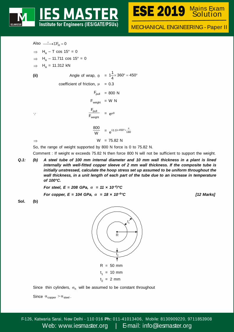
Q.1: (b) A steel tube of 100 mm internal diameter and 10 mm wall thickness in a plant is linedinternally with well-fitted copper sleeve of 2 mm wall thickness. If the composite tube isinitially unstressed, calculate the hoop stress set up assumed to be uniform throughout thewall thickness, in a unit length of each part of the tube due to an increase in temperatureof 100°C.
For steel, E = 208 GPa, = 11 × 10–6/°C
For copper, E = 104 GPa, = 18 × 10–6°C [12 Marks]Sol. (b)
t1
R
t2
R = 50 mm
t1 = 10 mm
t2 = 2 mm
Since thin cylinders, h will be assumed to be constant throughout
Since copper steel .

MECHANICAL ENGINEERING - Paper II
F-126, Katwaria Sarai, New Delhi - 110 016 011-41013406, Mobile: 8130909220, 9711853908Ph:
Web: www.iesmaster.org | E-mail: [email protected]
Mains Exam Solution
th,copper th,steel( R) ( R) , this will induce stresses in tube and sleeve.
h copper( ) will be compressible and h steel( ) will be tensile.
Assuming contact pressure P0,
h steel( ) =0
1
P D2t
; h copper = 0
2
P D2t
Radial displacement for steel due to pressure and temperature = h
ss
T RE
Radial displacement for copper = h
cC
T RE
(Radial displacement)copper =(Radial displacement)steel
hs
sT R
E
=h
cc
T RE
0 0
1 s c 2
P D P D1 12t E E 2t
= c s( ) T
0 0P 120 P 1201 12 10 208 1000 2 2 104 1000
= 7 × 10–6 × 100
P0 = 2.206 MPa
h steel =0
1
P D 2.206 120 13.236 MPa2t 2 10
h copper =0
2
P D 2.206 120 66.18 MPa2t 2 2
Q.1: (c) (i) What is kinematic pair? How are kinematic pairs classified? Explain. [6 Marks](ii) A four-bar mechanism has the following dimensions:
DA = 200 mm, CB = AB = 300 mm, DC = 500 mmThe link DC is fixed and the angle ADC is 60°. The driving link DA rotates uniformlyat a speed of 100 r.p.m. clockwise and constant driving torque has the magnitude of50 N-m. Determine the velocity of point B and angular velocity of the driven link CB.If the efficiency is 70%, calculate also the resisting torque: [6 Marks]
DC
B
A
60°
Sol. (i) Kinematic Pair: When two links of a machine is in contact, this contact is called a pair. If themotion between the links forming the pair is in a specific directions irrespective of the directionsof force, the pair is called kinematic pair and the motion of link is called as completely orsuccessfully constrained.


MECHANICAL ENGINEERING - Paper II
F-126, Katwaria Sarai, New Delhi - 110 016 011-41013406, Mobile: 8130909220, 9711853908Ph:
Web: www.iesmaster.org | E-mail: [email protected]
Mains Exam Solution
Classification of Kinematic Pair(1) Kinematic Pairs according to Relative Motion between links
(a) Turning Pair
(b) Sliding Pair
(c) Rolling Pair
(d) Screw Pair
(e) Spherical Pair
(2) Kinematic pair According to Nature of Contact
(a) Lower Pair
(b) Higher Pair
(3) Kinematic pair According to Mechanical construction
(a) Closed Pair
(b) Open (Forced-closed) Pair
(ii) 1 cm = 10cm
DA = 2cm
CB = AB = 3cm
DC = 5cm
I13 I14
I34C4
A2 B
I12
I23
60°
1
D
3
NAD = 100 rpm
VAD = A AB100V AD 0.2 2
60
= 0.2 × 10.472
VA = 2.094 m/s
By angular velocity ratio theorem
3
1
=
13 14
13 34
I II I
3 =5.8 10.472
11.4
3 = 5.328 rad/s (clockwise)
velocity of point B, VB = 3BC
= 0.3 × 5.328= 1.59 m/s
= output
input
P0.70
P

MECHANICAL ENGINEERING - Paper II
F-126, Katwaria Sarai, New Delhi - 110 016 011-41013406, Mobile: 8130909220, 9711853908Ph:
Web: www.iesmaster.org | E-mail: [email protected]
Mains Exam Solution
0.70 =3 3
1 1
TT
T3 =0.70 50 5.328
10.472
T3 = 17.81 N.mi.e. resisting torque = 17.81m
Q.1: (d) (i) The tension T in the spring as shown in the figure given below can be assumed to beconstant for small displacements. Determine the natural frequency of the verticalvibrations of the spring and also show that the period of vibration is greatest whena = b: [6 Marks]
TTx
b a
m1 2
(ii) A vibrating system has the following constants:W = 19.62 kg, K = 8 kg/cm, C = 0.08 kg-s/cmDetermine(1) damping factor;(2) natural frequency of damped oscillations;(3) logarithmic decrement.Here, W = Weight of massK = Spring stiffnessC = Damping coefficient [2 × 3 = 6 Marks]
Sol. (i)
T T
1T sin 2T sin
21
For small vibration, tan , sin , cos 1
1 = 2x x and b a
In equilibrium,
1 2T sin Tsin = mx
1 2Tx sin sinm
= 0

MECHANICAL ENGINEERING - Paper II
F-126, Katwaria Sarai, New Delhi - 110 016 011-41013406, Mobile: 8130909220, 9711853908Ph:
Web: www.iesmaster.org | E-mail: [email protected]
Mains Exam Solution
T 1 1x xm b a
= 0
Natural frequency,
n = T a b
m ab
Period of vibration
TP =
n
2 m 4abmab2T Ta b a b
Since AM GM
a b2
> ab
(a + b)2 4 abIf a = b, AM = GMHence TP will be greatest at a = b
(ii) mass (m) = 19.62 kg
K = 28 9.818kg/cm= N/m
10
= 7848 N/m
C = 20.08 9.81N s N s78.48
m m10
(1) Damping factor
C2m
= nC
2 km
=78.48 0.1
2 7848 19.62
(2) Natural damped frequency (d)
d = 2n1
where n =k 7848 20rad/secm 19.62
d = 21 20 19.899 rad/sec0.1
(3) Logarithmic decrement
n
n 1
xlog
x
= 2 2
2 2 0.1 0.631411 0.1
= 0.6314
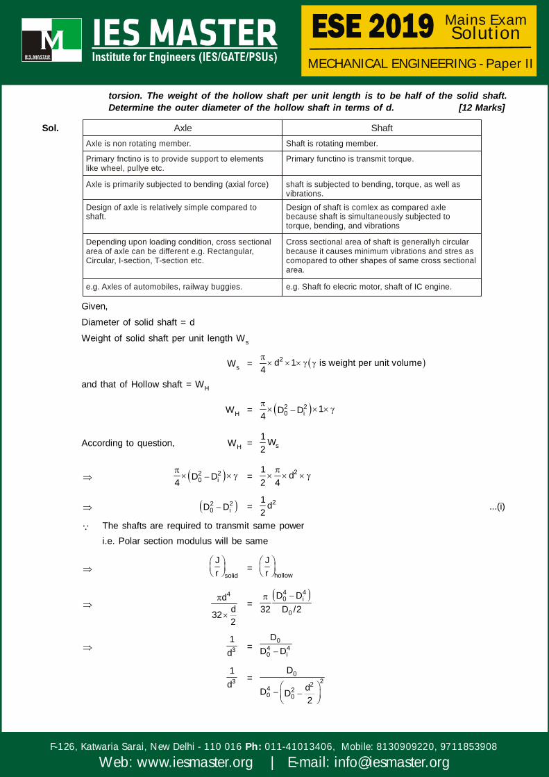
Q.1: (e) Differentiate between ‘shaft’ and ‘axle’. A solid shaft of diameter d is used in powertransmission. Due to the modification of existing transmission system, the solid shaft isrequired to be replaced by a hollow shaft of the same material and equally strong in

MECHANICAL ENGINEERING - Paper II
F-126, Katwaria Sarai, New Delhi - 110 016 011-41013406, Mobile: 8130909220, 9711853908Ph:
Web: www.iesmaster.org | E-mail: [email protected]
Mains Exam Solution
torsion. The weight of the hollow shaft per unit length is to be half of the solid shaft.Determine the outer diameter of the hollow shaft in terms of d. [12 Marks]
Sol. Axle ShaftAxle is non rotating member.
Primary fnctino is to provide support to elements like wheel, pullye etc.
Axle is primarily subjected to bending (axial force)
Design of axle is relatively simple compared to shaft.
Depending upon loading condition, cross sectional area of axle can be different e.g. Rectangular, Circular, I-section, T-section etc.
e.g. Axles of automobiles, railway buggies.
Shaft is rotating member.
Primary functino is transmit torque.
shaft is subjected to bending, torque, as well as vibrations.
Design of shaft is comlex as compared axle because shaft is simultaneously subjected to torque, bending, and vibrations
Cross sectional area of shaft is generallyh circular because it causes minimum vibrations and stres as comopared to other shapes of same cross sectional area.
e.g. Shaft fo elecric motor, shaft of IC engine.
Given,
Diameter of solid shaft = d
Weight of solid shaft per unit length Ws
Ws = 2d 1 is weight per unit volume4
and that of Hollow shaft = WH
WH = 2 20 i 1D D
4
According to question, WH = s1 W2
2 20 iD D
4 = 21 d
2 4
2 20 iD D = 21 d
2...(i)
The shafts are required to transmit same poweri.e. Polar section modulus will be same
solid
Jr
=
hollow
Jr
4dd322
=
4 40 i
0
D D32 D /2
31d
=0
4 40 i
DD D
31d
= 0224 2
0 0
D
dD D2

MECHANICAL ENGINEERING - Paper II
F-126, Katwaria Sarai, New Delhi - 110 016 011-41013406, Mobile: 8130909220, 9711853908Ph:
Web: www.iesmaster.org | E-mail: [email protected]
Mains Exam Solution
31d
= 044 4 2 2
0 0 0
DdD D D d4
1d
=0
2 20
4D4D d
2 204D d = 4dD0
2 20 04D 4dD d = 0
D0 =2 24d 16d 16d
8
D0 =d d 0.5d 0.707d2 2
D0 = 1.207d
Q.2: (a) The turbine rotor of a ship has a mass of 3000 kg. It has a radius of gyration of 0.45 mand a speed of 2000 r.p.m. clockwise when looking from stern. Determine the gyroscopiccouple and its effect on the ship—(i) when the ship is steering to the left on a curve of 100 m radius at a speed of 30 km/
hr;(ii) when the ship is pitching in a simple harmonic motion, the bow falling with its maximum
velocity. The period of pitching is 40 seconds and the total angular displacementbetween the two extreme positions of pitching is 12 degrees. [20 Marks]
Sol. Given
Mass of rotor (m) = 3000 kg
Mass of moment of inertia of rotor (I) = 2Gmr
where rG = 0.45m
I = 300 × (0.45)2 = 607.5 kg-m2
=2 N 2 2000 209.439 rad/sec60 60
(i) When ship steering to left
p = 530 m/secV 18 0.0833 rad/sec
R 100
Gyroscopic couple (C) = PI
= 607.5 × 209.439 × 0.0833
C = 10602.84 N-m
Effect
Activecouple
Reactivecouple
Bow will move upand stern will move
down
P

MECHANICAL ENGINEERING - Paper II
F-126, Katwaria Sarai, New Delhi - 110 016 011-41013406, Mobile: 8130909220, 9711853908Ph:
Web: www.iesmaster.org | E-mail: [email protected]
Mains Exam Solution
(ii) When Ship is Pitching:
12°
12 =6°2
n =2 2 0.157T 40
SHM = 6°
SHM velocity of pitching
P =ddt
where 0 tsin t
P = 0 n ncos t
For maximum pitching velocity t = 0
P = 0.157 6180
= 0.0164493 rad/sec
Gyroscopic couple (C) = PI
= 607.5 × 209.439 × 0.0164493
C = 2092.91 N-m
Effect
Activecouple
Reactivecouple
Ship will movetowards left direction
P
Q.2: (b) A steel cantilever of length 2 m of circular cross-section, 50 mm in diameter, carriesuniformly distributed load of intensity w. What is the maximum value of w so that deflectionat free end is not to exceed 1 mm? Find out the slope at free end. Take E = 200 GPa.
[20 Marks]
Sol.x
x
w N/m
x
length of beam = 2 mDiameter of beam, d = 50 mm
Intensity of UDL = wMaximum allowable deflection of free end = 1 mm
B = ?
E = 200 GPa = 5 22 10 N mm


MECHANICAL ENGINEERING - Paper II
F-126, Katwaria Sarai, New Delhi - 110 016 011-41013406, Mobile: 8130909220, 9711853908Ph:
Web: www.iesmaster.org | E-mail: [email protected]
Mains Exam Solution
Bending moment at section X-X (Mx) = 2x x x
2 2
using double integral theorem.2
2d yEIdx
=2
x xxM2
Integrating w.r.t.x
dyEIdx
=3
1x C6
EI y =4
1 2x C x C
24
Boundary condition(i) at x = L, y = 0
(ii) at x = L, dy 0dx
So, from boundary condition
C1 =3 4 4 4
2L L L L,C6 24 6 8
EI(y) =4 3 4x L Lx
24 6 8
We know that, Moment of inertia, I = 4d64
I = 4 3 450 306.796 10 mm64
At x = 0, y = ymax = 1mm
ymax =4L1
8EI
= 4
5 3w 2000
8 2 10 306.796 10
= 0.0307 N/mm = 30.7 N/mAlso, slope at free end of cantilever, at x = 0,
dy/dx = B =3 3
35 3
w 0.0307 2000 0.667 10 rad6EI 6 2 10 306.796 10
l
Q.2: (c) A thick cylinder is subjected to both internal and external pressure. The internal diameterof the cylinder is 200 mm and the external diameter is 250 mm. If the maximum permissiblestress is 30 N/mm2 and the external pressure is 8 N/mm2, determine the intensity of internalradial pressure. [20 Marks]
Sol. Given: Thick cylinder,
Internal pressure, P1 = ?External Pressure, P2 = 8 N/mm2
Internal radius, r1 = 100 mmExternal radius, r2 = 125 mm

MECHANICAL ENGINEERING - Paper II
F-126, Katwaria Sarai, New Delhi - 110 016 011-41013406, Mobile: 8130909220, 9711853908Ph:
Web: www.iesmaster.org | E-mail: [email protected]
Mains Exam Solution
Maximum Permissible stress, P = 230N mm
From Lame’s equation
radial stress, r = 2BAr
..(i)
and hoop stress, = 2BAr
...(ii)
B.C are : r = r1 r 1P and 2 r 2r r P
From equation (i), we get
–P1 = 22 21 2
B BA and P Ar r
1 2P P =2 22 1
2 2 2 21 2 1 2
1 1 r rB B
r r r r
B = 2 2
1 21 22 22 1
r r P Pr r
and A = 2
1 221 12 2 2
1 2 1
r P PBP Pr r r
=2 2 2 2
1 1 1 22 1 2 22 22 1
P r P r r P r Pr r
=2 2
1 21 22 22 1
P r P rr r
Now, eqn. (2), gives
= 2 22 2
1 21 21 21 22 2 2 2 22 1 2 1
r r P PP r P r 1r r r r r
Since hoop stress is maximum at r = r1, so
30 = 2 22 2
112 2 2 2 2
100 125 P 8P 100 8 125 1125 100 125 100 100
30 5625 = 1 110000P 125000 15625P 125000
125625P = 418750
P1 = 16.34 N/mm2
Q.3: (a) A horizontal gas engine running at 200 r.p.m. has a bore of 200 mm and a stroke of 400mm. The connecting rod is 900 mm long and the reciprocating parts weigh 20 kg. Whenthe crank has turned through an angle of 30° from the inner dead centre, the gas pressureson the cover and the crank sides are 500 kN/m2 and 60 kN/m2 respectively. The diameterof the piston rod is 40 mm. Determine—(i) Turning moment on the crankshaft;(ii) Thrust on the bearings;(iii) Acceleration of the flywheel which has a mass of 8 kg and radius of gyration of 600
mm while the power of the engine is 22 kW. [20 Marks]

MECHANICAL ENGINEERING - Paper II
F-126, Katwaria Sarai, New Delhi - 110 016 011-41013406, Mobile: 8130909220, 9711853908Ph:
Web: www.iesmaster.org | E-mail: [email protected]
Mains Exam Solution
Sol. 30°P2
P1
r = L 200mm L is stroke2
n =L 900 2 N4.5, 20.943 rad/secr 200 60
sin =sin sin30sin
n 4.5
= 6.379°
(i) Pressure force on piston (FP)FP = P1A1 – P2(A1 – AP)
= 2 2 2500 (0.2) 60 (0.2) (0.04)4 4
= 13.898 kN
(ii) Inertia force on piston (FI)
FI =2
recicos2m r cos
n
= 2 cos6020 0.2 cos 3020.9434.5
FI = 1.714 kN
(iii) Gravity force due to weight of cylinder (Fg)
Since gas engine is horizontal so Fg = 0
Total force on piston (F) = FP – FI
F = 13.898 – 1.714
F = 12.184 kN
(i) Turning moment on crank shaft (Tr)
Ft = F sin
cos
Tr =
F sin r 12.184 0.2 sin 30 6.37
cos cos 6.37
Tr = 1.454 kN-m
(ii) Thrust load on bearings (FTh)
FTh = Fcos
cos
=
12.184 cos 30 6.37
cos 6.37
FTh = 9.87 kN

MECHANICAL ENGINEERING - Paper II
F-126, Katwaria Sarai, New Delhi - 110 016 011-41013406, Mobile: 8130909220, 9711853908Ph:
Web: www.iesmaster.org | E-mail: [email protected]
Mains Exam Solution
(iii) Acceleration of fywheel ( )
Tmean =3Power 60 22 10 60 1050.42N m
2 N 2 200
T = I where meanT T T
1454 – 1050.42 = 2Gmr where, is angular acceleration of flywheel
403.58 = 28 0.6
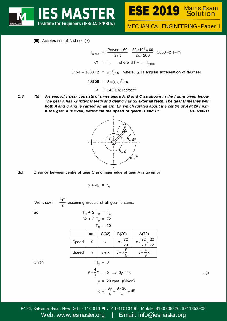
= 2140.132 rad/secQ.3: (b) An epicyclic gear consists of three gears A, B and C as shown in the figure given below.
The gear A has 72 internal teeth and gear C has 32 external teeth. The gear B meshes withboth A and C and is carried on an arm EF which rotates about the centre of A at 20 r.p.m.If the gear A is fixed, determine the speed of gears B and C: [20 Marks]
F
B
CA
E
Sol. Distance between centre of gear C and inner edge of gear A is given by
C Br 2r = rA
We know r = mT2
assuming module of all gear is same.
So TC + 2 TB = TA
32 + 2 TB = 72
TB = 20
arm C(32) B(20) A(72)32 32 20Speed 0 x x x20 20 728 4Speed y y x y x y x5 9
Given NA = 0
4y x9
= 0 9y= 4x ...(i)
y = 20 rpm (Given)
x =9y 9 20 454 4

MECHANICAL ENGINEERING - Paper II
F-126, Katwaria Sarai, New Delhi - 110 016 011-41013406, Mobile: 8130909220, 9711853908Ph:
Web: www.iesmaster.org | E-mail: [email protected]
Mains Exam Solution
Speed of gear B (NB)
NB =8 45 8y x 20 52rpm5 5
Negative sign show that B is rotating in opposite direction as that of arm rotation.
Speed of gear (NC)
NC = y + x
NC = 20 + 45 = 65 rpm
In same direction as rotation of arm
Q.3: (c) A single-cylinder reciprocating engine has a speed of 300 r.p.m., stroke 300 mm, mass ofreciprocating parts 50 kg, mass of revolving parts at 150 mm radius 37 kg. If two-thirds ofthe reciprocating parts and all the revolving parts are to be balanced, find—(i) the balance mass required at a radius of 300 mm;(ii) the residual unbalanced force when the crank has rotated 60° from top dead centre.
[10 Marks]
Sol. Rotating mass (mr) = 37 kg
Reciprocating mass (mreci) = 50 kg
r =300 150mm
2
Mass need to balanced (mun) = 2 50 37 70.33 kg3
(i) Balance mass required: (mbal)For dynamic balancing couple of both system should be same i.e.
mun × rcrank = mbal × rbalance
70.33 × 0.15 = mbal × 0.3
mbal = 35.165 kg
(ii) Residual unbalance force
Horizontal unbalance force (FH) = 2mr cos1 C
Where C =2, 603
FH =22 2 30050 0.15 cos601
3 60
FH = 1233.7 N
Vertical unbalance force (Fv) = 2cmr sin
=22 2 30050 0.15 sin60
3 60
Fv = 4273.667 N
Total unbalance force (Fun) = 2 2H VF F
Fun = 4448.17N

MECHANICAL ENGINEERING - Paper II
F-126, Katwaria Sarai, New Delhi - 110 016 011-41013406, Mobile: 8130909220, 9711853908Ph:
Web: www.iesmaster.org | E-mail: [email protected]
Mains Exam Solution
Q.3: (d) Draw the shear force and bending moment diagram for the cantilever beam as shown inthe figure below: [10 Marks]
20 kN 40 kN 20 kN
A B C2 m
3 m
Sol. Sign Convections
For shear
+ve –ve
20 kN 40 kN 20 kN
C
2 m1 m
A B
For BM
+ve –ve
Shear force at ‘A’
VA = – 20 kN
Shear force just before ‘B’ = – 20 – 20 ×1 = – 40 kN
Shear force just after ‘B’ = – 20 – 20 × 1 – 40 = – 80 kN
Shear force at ‘C’ = – 20 – 20 × 3 – 40 = – 120 kN
And
Bending moment at ‘A’ = 0 {Free end}
Bending moment at ‘B’ = 120 1 20 1 30 kN m2
Bending moment at ‘C’ =320 3 40 2 20 32
= – 230 kN-m
20 kN 40 kN 20 kN/m
C2 m1 mA B
20 kN
(–)40 kN
80 kN
120 kN
SFD
BMD30 kN-m
230 kN-mParabolic
Q.4: (a) (i) Describe angular contact bearings and taper roller bearings with the help of neatsketches. Also, cite at least two advantages and two disadvantages of each.
[8 Marks](ii) A pair of spur gears with 20° full-depth involute teeth consists of a 20 teeth pinion
meshing with a 41 teeth gear. The module is 3 mm while the face width is 40 mm. Thematerial for both the pinion and the gear is steel having an ultimate tensile strengthof 660 N/mm2. The gears are heat-treated to a surface hardness of 400 BHN. The


MECHANICAL ENGINEERING - Paper II
F-126, Katwaria Sarai, New Delhi - 110 016 011-41013406, Mobile: 8130909220, 9711853908Ph:
Web: www.iesmaster.org | E-mail: [email protected]
Mains Exam Solution
pinion rotates at 1500 r.p.m. and the service factor is 2.0. Assume that the velocityfactor accounts for the dynamic load and the factor of safety is 1.5. Determine therated power that the gears can transmit. Assume a Lewis form factor of 0.32.
[12 Marks]Sol. (i) Angular Contact Bearing: In angular contact bearing, the grooves in inner and outer races are
so shaped that the line of reaction at the contact between balls and races makes an anglewith the axis of the bearing. This reaction has two components angular contact bearing cantake radial and thrust loads.
Advantages:(a) Angular contact bearing can take both radial and thrust loads.
(b) In angular contact bearing, one side of the groove in the outer race is cut away to permit theinsertion of larger number of balls than that of deep groove ball bearing. This permits the bearing to carryrelatively large axial and radial loads. Therefore, the load carrying capacity of angular contact bearingis more than that of deep groove ball bearing.
Disadvantags:(a) Two bearings are required to take thrust load in both directions
(b) The angular contact bearing must be mounted without axial play.
Taper Roller Bearing: The taper roller bearing consists of rolling elements in the form of a frustum ofcone. They are arranged in such a way that the axes of individual rolling elements intersect in a commonapex point on the axis of the bearing. In kinematics analysis, this is the essential requirement for purerolling motion between conical surfaces. In taper roller bearing, the line of resultant reaction through therolling elements make an angle with the axis of the bearing. Therefore, taper roller bearing can carry bothradial and axial loads.
Outer race or cup
Roller
Iner race or cone
Advantages:(a) Taper roller bearing can take heavy radial and thrust loads.
(b) Taper roller bearing has more rigidity
Disadvantages:(a) It is necessary to use two taper roller bearings on the shaft to balance the axial force.
(b) It is necessary to adjust the axial position of the bearing with pre-load. This is essential to coincidethe apex of the cone with the common apex of the rolling elements.
MECHANICAL ENGINEERING - Paper II
F-126, Katwaria Sarai, New Delhi - 110 016 011-41013406, Mobile: 8130909220, 9711853908Ph:
Web: www.iesmaster.org | E-mail: [email protected]
Mains Exam Solution
(ii) Given: = 20° full depth involute teeth
TP = 20, TG = 41, m = 3mm, b = 40mm
ut = 660 N/mm2, BHN = 400, NP = 1500 rpm, Cs = 2, fos = 1.5
Lewis form factor, y = 0.32
dP = mTP = 3 × 20 = 60 mm
Since both pinion and gear are made of same material, so design is done on the basis of pinion gearas it is weaker.
Velocity of pinion, V = 1 1P P3
d N 4.71ms 10ms60 10
So Cv =3 3 0.389
3 V 3 4.7
Beam strength, Sb = b660mb y 3 40 0.32 8448N3
Wear strength, Sw = PbQd K
=2
gP
g P
2T BHNb d 0.16T T 100
=22 41 40040 60 0.16
41 20 100
= 8259.147 NSince beam strength is lower than wear strength, So design is done on basis of beam strength
Effective load on tooth, Peff = s s
tv v P
C C 2T 2 2TP 171T NewtonC C d 0.389 0.06
In order to avoid failure of tooth in bending,Sb = Peff × FOS
8259.147 = 171 T × 1.5 T = 32.199 Nm
P =32.199 2 1500T 5057.87 watt
60
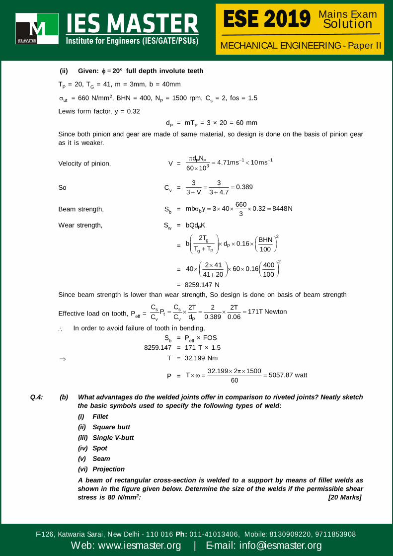
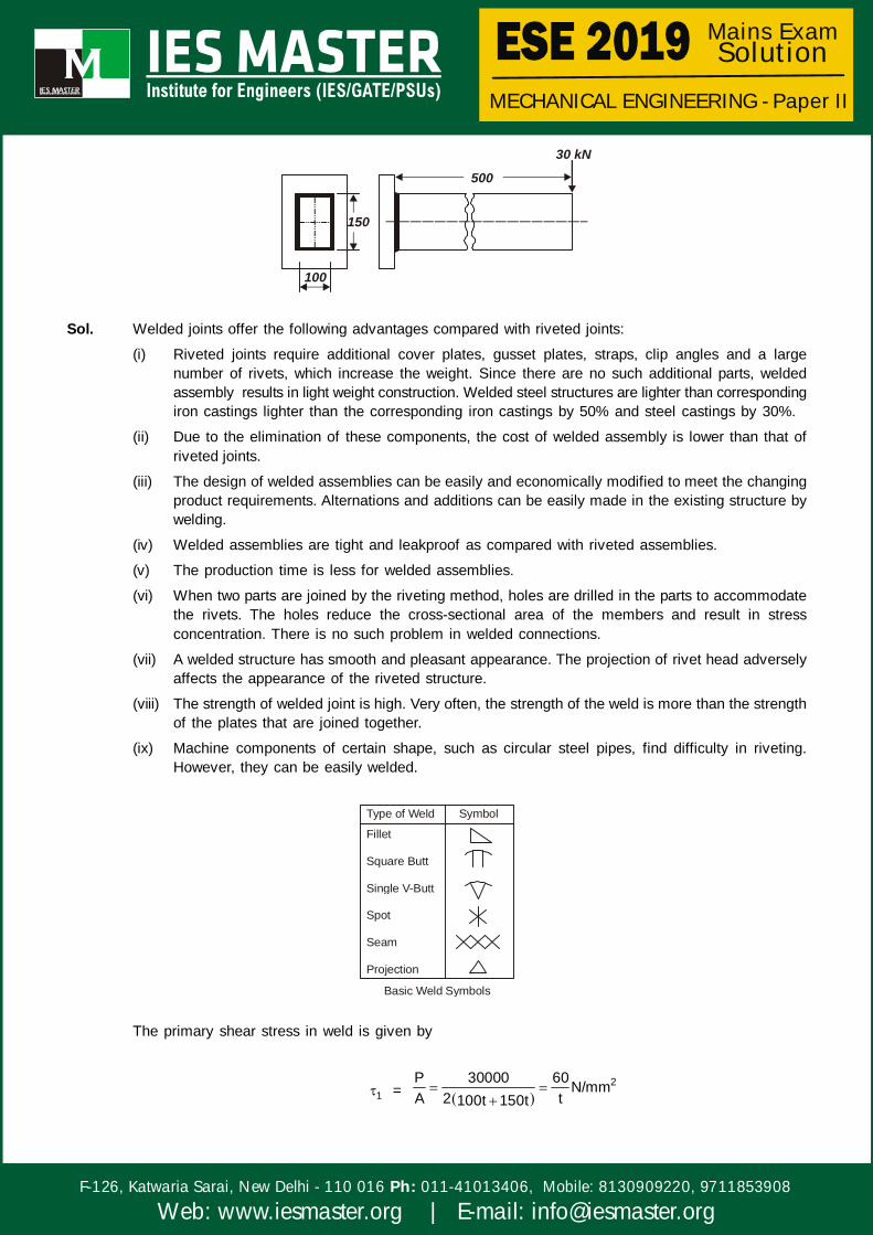
Q.4: (b) What advantages do the welded joints offer in comparison to riveted joints? Neatly sketchthe basic symbols used to specify the following types of weld:(i) Fillet(ii) Square butt(iii) Single V-butt(iv) Spot(v) Seam(vi) ProjectionA beam of rectangular cross-section is welded to a support by means of fillet welds asshown in the figure given below. Determine the size of the welds if the permissible shearstress is 80 N/mm2: [20 Marks]
MECHANICAL ENGINEERING - Paper II
F-126, Katwaria Sarai, New Delhi - 110 016 011-41013406, Mobile: 8130909220, 9711853908Ph:
Web: www.iesmaster.org | E-mail: [email protected]
Mains Exam Solution
150
100
500
30 kN
Sol. Welded joints offer the following advantages compared with riveted joints:
(i) Riveted joints require additional cover plates, gusset plates, straps, clip angles and a largenumber of rivets, which increase the weight. Since there are no such additional parts, weldedassembly results in light weight construction. Welded steel structures are lighter than correspondingiron castings lighter than the corresponding iron castings by 50% and steel castings by 30%.
(ii) Due to the elimination of these components, the cost of welded assembly is lower than that ofriveted joints.
(iii) The design of welded assemblies can be easily and economically modified to meet the changingproduct requirements. Alternations and additions can be easily made in the existing structure bywelding.
(iv) Welded assemblies are tight and leakproof as compared with riveted assemblies.
(v) The production time is less for welded assemblies.
(vi) When two parts are joined by the riveting method, holes are drilled in the parts to accommodatethe rivets. The holes reduce the cross-sectional area of the members and result in stressconcentration. There is no such problem in welded connections.
(vii) A welded structure has smooth and pleasant appearance. The projection of rivet head adverselyaffects the appearance of the riveted structure.
(viii) The strength of welded joint is high. Very often, the strength of the weld is more than the strengthof the plates that are joined together.
(ix) Machine components of certain shape, such as circular steel pipes, find difficulty in riveting.However, they can be easily welded.
Type of Weld Symbol
Fillet
Square Butt
Single V-Butt
Spot
Seam
Projection
Basic Weld Symbols
The primary shear stress in weld is given by
1 = 2P 30000 60N/mm
A 2 t100t 150t


MECHANICAL ENGINEERING - Paper II
F-126, Katwaria Sarai, New Delhi - 110 016 011-41013406, Mobile: 8130909220, 9711853908Ph:
Web: www.iesmaster.org | E-mail: [email protected]
Mains Exam Solution
The bending moment Mb is given by
Mb = Pe = 30000 × 500 = 15 × 106 Nmm
The polar moment of inertia of all welds about axis of bending i.e. x -axis
lxx =3 2 3150 t 100 t1502 100t12 122
Since t is less compared to length so
Ixx =23150 t 1502 100t
12 2
= 75 × 1502 t mm4
Therefore, the bending stress b is given by
b =6
b2
M r 15 10 75I 75 150 t
= 2666.66N/mmt
The minimum shear stress in the weld is given by
= 2 2 2
b 21
666.66 602 2t t
= 2338.69N / mmt
Since the permissible shear-stress in the weld is 80 N/mm2
80 = 2338.69 N/mmt
t =338.69 4.23mm
80
Leg length of the weld
h =t 5.98 6 mm
0.707
Q.4: (c) A shaft is subjected to a maximum torque of 10 kN-m and a maximum bending momentof 7.5 kN-m at a particular section. If the allowable equivalent stress in simple tension is160 MN/m2, find the diameter of the shaft according to (i) maximum shear stress theory,(ii) strain energy theory and (iii) shear strain energy theory. Take Poisson’s ratio as 0.24.
[20 Marks]Sol. Given
Torque, T = 10 kN-m
Bending moment, M = 7.5 kN-m
Allowable equivalent stress in simple tension = 160 MN/m2 = 160 N/mm2
Poisson’s ratio = 0.24
Let the diameter of shaft be ‘D’ mm.

MECHANICAL ENGINEERING - Paper II
F-126, Katwaria Sarai, New Delhi - 110 016 011-41013406, Mobile: 8130909220, 9711853908Ph:
Web: www.iesmaster.org | E-mail: [email protected]
Mains Exam Solution
(i) Maximum shear stress theoryAccording to this theory,
max yf 1
FOS2
max = y1 2 f2 2
2 2 2 2
316 160M M T M M T
2 2D
2 2 2 2
63
16 7.5 7.5 10 7.5 7.5 10 10 802D
D 116.75 mm(ii) Strain energy theory:According to this theory
2 21 2 1 22
2yf
FOS
2
2 22 2 2 2 2 2 2 23
162 0.24M M T M M T M M T M M TD
2yf
FOS
2
2 22 2 2 23
167.5 7.5 10 7.5 7.5 10D
122 2 2 2 102 0.24 7.5 7.5 10 7.5 7.5 10 2160
D 88.46 mm(iii) Shear strain energy theoryAccording to this theory,
2 21 2 1 2
2yf
FOS
22
2 2 y2 2 22 2 2 23f16
M M TM M T M M TD FOS
2
2 2 12 22 2 22 2 2 2316 10 1607.5 7.5 107.5 7.5 10 7.5 7.5 10D
D 90.01 mm

MECHANICAL ENGINEERING - Paper II
F-126, Katwaria Sarai, New Delhi - 110 016 011-41013406, Mobile: 8130909220, 9711853908Ph:
Web: www.iesmaster.org | E-mail: [email protected]
Mains Exam Solution
SECTION–B
Q.5: (a) Describe the following microconstituents of iron-carbon alloys in relation to the phasespresent, arrangement of phases and their relative mechanical properties: [12 Marks](i) Spheroidite(ii) Pearlite(iii) Bainite(iv) Martensite
Sol: (i) Spheroidite: If a steel alloy having either pearlitic or bainitic microstructures is heated to and leftat, a temperature below the eutectoid for a sufficiently long period of time –for example, at about700°C (1300°F) for between 18 and 24 h–yet another microstructure will form. It is called spheroidite.Instead of the alternating ferrite and cementite lamellae (pearlite), or the microstructure observedfor bainite, the Fe3C phase appears as sphere-like particles embedded in a continuous phasematrix.
There is less boundary area per unit volume in spheroidite, and consequently plastic deformationis not nearly as constrained, which gives rise to relatively soft and weak material. In fact, of allsteel alloys, those that are softest and weakest have a spheroiditie microstructure.
As would be expected, spheroidized steels are extremely ductile, much more than either fine orcoarse pearlite. In addition, they are notably tough because any crack can encounter only a verysmall fraction of the brittle cementite particles as it propagates through the ductile ferrite matrix.
(ii) Pearlite:
Cooling
Heating0.77%CAustenite Ferrite 0.02%C Cementite 6.67%C
In the reaction, the simultaneous formation of ferrite and cementite from austenite results at thetemperature of 723°C and composition of 0.80% carbon. There are nearly 12% of iron carbideand slightly more than 88% of ferrite in the resulting mixture. Since the ferrite and cementite areformed simultaneously, they are intimately mixed. Characteristically, the mixture is lamellar, i.e. itis composed of alternate layers of ferrite and cementite. This mocrostructure is called pearlite,which is very important in iron and steel technology, because it can be formed in almost all steelsby mean of suitable heat treatments.
(iii) Bainite: The microstructure of bainite consists of ferrite and cementite phases, and thus diffusionalprocesses are involved in its formation. Bainite forms as needles or plates, depending on thetemperature of the transformation. Because bainitic steels have a finer structure (i.e., smaller
ferrite and Fe3C particles), they are generally stronger and harder than pearlitic ones; yet theyexhibit a desirable combination of strength and ductility.
(iv) Martensite: Martensite has a body centered tetragonal (BCT) structure. As martensite has fewslip systems (along which dislocation moves) as compared to BCC structure, it is extremely hardand brittle. It lacks toughness and has negligible ductility. Martensite is formed when austenitezediron carbon alloys are rapidly cooled (or quenched) to a relatively low temperature (in the vicinityof the ambient). Martensite is a nonequilibrium single phase structure that results from a diffusionlesstransformation of austenite.
Q.5: (b) In an orthogonal cutting operation, the cutting speed is 2.5 m/s, rake angle is 6° and thewidth of cut is 10 mm. The undeformed chip thickness is 0.2 mm. 13.36 grams of steelchips with total length of 50 cm are obtained. The tool post dynamometer gives cutting andthrust forces as 1134 N and 453.6 N respectively. Find—


MECHANICAL ENGINEERING - Paper II
F-126, Katwaria Sarai, New Delhi - 110 016 011-41013406, Mobile: 8130909220, 9711853908Ph:
Web: www.iesmaster.org | E-mail: [email protected]
Mains Exam Solution
(i) shear plane angle;(ii) friction energy at tool-chip interface as percentage of total energy;(iii) specific cutting energy.Assume density of steel = 7.8 grams/cm3. [12 Marks]
Sol. Given that,Cutting speed, V = 2.5 m/s
Rake angle, = 6°
Width of Cut, b = 10 mm = 210 m
Underformed chip thickness, t = 0.2 mmMass of steel chips, m = 13.36 grams
Total length of chip, l = 50 cm = 0.5 m
Cutting force, FC = 1134 NThrust Force, Ft = 453.6 N
Density of steel, l = 7.8 gm/cm3
Let chip thickness = tC Mass = Density × Volume
m = Cb t l
13.36 = 1C7.8 50 10 10 t
tC = 0.0342cm 0.342mm
Chip thickness ratio, r =C
tt
=0.2 0.584
0.342
(i) Shear plane angle, ( )
tan =r cos
1 r sin
tan =0.584 cos6 0.618
1 0.584 sin6
= 1tan 31.7390.618
(ii) Friction Force (F)
F = C tF sin F cos
F = 1134 sin6 453.6 cos6 569.65N
Shear force (FS)
FS = C tF cos F sin
FS = 1134 cos31.739 453.6 sin31.739
= 725.79 N

MECHANICAL ENGINEERING - Paper II
F-126, Katwaria Sarai, New Delhi - 110 016 011-41013406, Mobile: 8130909220, 9711853908Ph:
Web: www.iesmaster.org | E-mail: [email protected]
Mains Exam Solution
Total Energy = Friction Energy + Shear Energy
FC × V = C S SF V F V ...(i)
Chip Velocity, VC = V sin
cos
VC = 2.5 sin31.739 1.459m scos 31.739 6
Friction energy as percentage of total energy,
=C
C
F V 100%F V
=569.65 1.459 100%
1134 2.5
= 29.33%
(iii) Specific cutting energy, E = C 3F 1134 0.567J mm1000bd 1000 10 0.2
Q.5: (c) Describe four tests of flexibility that an automated manufacturing system should satisfy toqualify as being flexible. Also list the application areas where FMS technology is successfullyemployed. [12 Marks]
Sol. Test of flexibility : To quality as being flexible, a manufacturing system should satisfy several criteria.The four following test of flexibility in an automated manufacturing system are :1. Part Variety Test: Can the system process different part styles in a nonbatch mode ?2. Schedule Change Test: Can the system reading accept changes in production schedule, and
changes in either part mix or production quantity.3. Error recovery Test: Can the system recover quickly from equipment break downs, so that the
production is not completely distrupted4. New part Test: Can new part designs introduced into the existing product mix with relative ease.
If the answer of all these question is “yes” for a given manufacturing system, the system can beconsidered flexible.
The most effective FMS applications are in medium quantity batch production. When a variety ofparts is to be produced, FMS is suitable for production quantities typically upto 15000 to 35000aggregate parts/year. Most of the experience in FMS has been gained in machining applications.
Q.5: (d) Describe at least five main functions carried out by coating on electrode in electric arcwelding process. Also, list the constituents of coating and their purpose. [12 Marks]
Sol: Electrode coating and its functions: Coating or cover on the electrode core wire is provided withvarious hydrocarbon compound and elements to perform specific roles as discussed later in the followingtext. But the important function of providing arc shielding is of prime interest.
The important functions are as under:(i) Improve the electric conductivity in the arc region to improve the arc ignition and stabilization of
the arc.
(ii) Slag formation influences size of molten metal droplet, protects the droplet during transfer andweld pool from atmospheric gases.

MECHANICAL ENGINEERING - Paper II
F-126, Katwaria Sarai, New Delhi - 110 016 011-41013406, Mobile: 8130909220, 9711853908Ph:
Web: www.iesmaster.org | E-mail: [email protected]
Mains Exam Solution
(iii) Provide deoxidizers like Si and Mn, alloying elements such as Cr, Ni, Mo to improve weld metalproperties.
(iv) Improve metal deposition rate with addition of iron powder in coating.
(v) Controlled alloying of the weld metal to achieve specific properties can be done by incorporatingrequired alloying elements in electrode coatings.
Coating Constituent Function
Cellulose
Calcium Fluoride (CaF )
Clay (Aluminum Silicate)
Talc (Magnesium Silicate)
Rutile (TiO )
Iron Oxides
Calcium Carbonate
Asbestos
Quartz (SiO )
Sodium Silicate/Potassium Silicate
FeMn / FeSi
Iron Powder
Powdered Alloys
2
2
2
Gas former
Slag basicity and metal fluidity, H removal
Slag former
Slag former
Arc stabilizer, Slag former, Fluidity
Fluidity, Slag former
Gas former, Arc stabilizer
Coating strength
Slag fluidity, Slag former
Binder, Arc stabilizer
Deoxidizer
Deposition Rate
Alloying
2
Q.5: (e) Explain the distinction between the following using block diagrams and examples:[6+6 Marks]
(i) Measurement systems and Control systems(ii) Open-loop systems and Closed-loop systems
Sol: (i) Measurement systems: A fundamental part of many mechatronics system is a measurementsystem used for making measurements.
Figure given below indicates the functional elements of an instrument by various blocks.
Physical variableto be measured
Input
SignalPrimary sensing
element
Variable conversion
element
Variable manipulation
element
Datatransmission
element
Dataprocessing
element
Datapresentation
elementObserver
As an example, consider a thermocouple-based digital temperature measurement system shown infigure below:
Thermocouple AmplifierA/D and display decoder LED display
Transducer Signal processor Recorder
Figure: Measurement system


MECHANICAL ENGINEERING - Paper II
F-126, Katwaria Sarai, New Delhi - 110 016 011-41013406, Mobile: 8130909220, 9711853908Ph:
Web: www.iesmaster.org | E-mail: [email protected]
Mains Exam Solution
Control systems:
Fig. Block diagram representing closed-loop control system
Controller Servo motorload
Errorsignal
Output
Sensor for tablemovement
Set point
Errordetector
As an example temperature control in a Metal-melting furnace
Pressuregauge
Furnace
BurnerOil
AirActuator
To c
him
ney
Furnace pressure control system
(ii) Open-loop systems and Closed-loop systemsOpen-loop control systems
A good example of an open-loop control system is shown in Figure. The input signal or command signalis given to the machine tool to perform the required machining operations. The tool moves with respectto a command signal given by the operator. There is no return signal to verify whether the tool hasmoved to the correct position or not (this is why it is called non-feedback or open-loop system). Thus,the error is not found and therefore, not corrected. E.g. Traffic Light Signal
ControllerStepping
motorSet pointor input
Output
Fig. Block diagram representing an open-loop system
Closed-loop control systemsThe input signal is given to the machine and the table moves. The feedback device (transducer) isconnected to the table, which senses the movement and positions the table. After sensing, the transducerconverts this mechanical movement into an electrical signal. This electrical signal is then fed to the errordetector device for comparison with set value or reference value called an error signal (error is thedifference between the measured output to the set value). Then, this error signal is sent to the controllerfor rectifying the error by operating the servo motor. E.g. Temperatgure control in refrigeration system

MECHANICAL ENGINEERING - Paper II
F-126, Katwaria Sarai, New Delhi - 110 016 011-41013406, Mobile: 8130909220, 9711853908Ph:
Web: www.iesmaster.org | E-mail: [email protected]
Mains Exam Solution
Fig. Block diagram representing closed-loop control system
Controller Servo motorload
Errorsignal
Output
Sensor for tablemovement
Set point
Errordetector
Q.6: (a) (i) In an open die forging, a strip 150 mm wide, 4 mm long and 10 mm thick is compressedin plane strain such that the dimension 400 remains same. The yield strength ofmaterial in uniaxial compression is equal to 200 N/mm2. Find the minimum, averageand maximum die pressures at the beginning of plastic deformation if the coefficientof friction on the interface between the die and the material is equal to 0.1.
[10 Marks](ii) For a product, the purchase prices are given below:
i
1
2
3
Sl. No. Order quantity (Q ) Unit prices ( )1 Q 500 10.002 500 Q 750 9.253 Q 750 8.75
`
Determine the optimum purchase quantity if the annual demand of the product is 2400units. The cost of ordering is ` 100 and the inventory carrying charge is 24% of thepurchase price per year. [10 Marks]
Sol. (i)
Length of outer edge from centre of strip (L) = b 1502 2 = 75 mm
Sticking zone length, (xs) =h 1L n2 2
xs =10 175 n
2 0.1 2 0.1
xs = –5.47 (so there is only sliding zone)
Sliding zone 0 x 75 mm .
Pressure variation in sliding zone is given by
P =2 (L x)h2ke
Maximum pressure at x = 0 i.e.,
Pmax =2 Lh2ke
where k =y
3
(From von mises theory)
k =200
3 = 115.47 N/mm2

MECHANICAL ENGINEERING - Paper II
F-126, Katwaria Sarai, New Delhi - 110 016 011-41013406, Mobile: 8130909220, 9711853908Ph:
Web: www.iesmaster.org | E-mail: [email protected]
Mains Exam Solution
Pmax =2 0.1 75
102 115.47 e
= 1035.00 N/mm2
2maxP 1035 N / mm
Minimum pressure is at x = L, i.e.
Pmin = 2ke = 2k = 230.94 N/mm2
2minP 230.94 N / mm
Mean pressure (Pmean):
Pmean × L =L
oPdx
Pmean × 75 =2 (L x)75 h
02ke
= 40203.06
2meanP 536.04 N / mm
(ii) Annual Demand D = 2400
Ordering cost per order C0 = ` 100
Carrying cost per unit per year, Cc = 0.24 Where p = purchasing price per unit
Case-I: When Q < 500, p = 10
EOQ =0
c
2DC 2 2400 100 447.2 447C 0.24 10
Total cost per year
TC1 = 0 cp D 2DC C
= 10 2400 2 2400 100 0.24 10
= ` 25073.3
Case-II When 500 Q 750, p 9.25
EOQ =0
c
2DC 2 2400 100 465C 0.24 9.25
This is not feasible
Case-III: When Q 750, p 8.75
EOQ =0
c
2DC 2 2400 100 478C 0.24 8.75
This is not feasibleTotal cost per year at Q = 500,
Tc2 = 0 cD Qp D C CQ 2
=2400 5009.25 2400 100 0.24 9.25500 2
= 22200 + 480 + 555 = ` 23235


MECHANICAL ENGINEERING - Paper II
F-126, Katwaria Sarai, New Delhi - 110 016 011-41013406, Mobile: 8130909220, 9711853908Ph:
Web: www.iesmaster.org | E-mail: [email protected]
Mains Exam Solution
Total cost per year at Q = 750
Tc3 = c 0Q Dp D C C2 Q
=750 24008.75 2400 0.24 8.75 100
2 750
= 21000 + 787.5 + 320 = ` 22107.5
Out of Tc1, Tc2 and Tc3, the minimum value is for Tc3. Hence the optimum order size = 750
Q.6: (b) What is a eutectoid reaction? Explain the development of microstructure in iron-carbonalloys of hypoeutectoid, eutectoid and hypereutectoid compositions when they are cooledfrom high temperature with the help of neatly labelled diagrams indicating the phasespresent. [20 Marks]
Sol. The iron-iron carbide eutectoid reaction is fundamental to the development of pearlite microstructure insteel alloys.
Cooling3Heating
Fe C0.76 wt%C 6.70 wt%C0.022wt%C ...(i)
Development of microstructure in iron-carbon alloys:Eutectoid: An alloy of eutectoid composition (0.76 wt% C) as it is cooled from a temperature within the phase region, say, 800°C–that is, beginning at point a in figure. and moving down the vertical line xx’.Initially, the alloy is composed entirely of the austenite phase having a composition of 0.76wt% C andcorresponding microstructure, also indicated in figure. As the alloy is cooled, there will occur no changesuntil the eutectoid temperature (727°C) is reached. Upon crossing this temperature to point b, theaustenite transforms according to equation (i).
1100
1000
900
800
700
600
500
4000 1.0
Composition (wt% C)2.0
x
3Fe C
b
Tem
pera
ture
(°C
)
727°C
3Fe C
Figure: Schematic representations of themicrostructures for an iron-carbonalloy of eutectoid composition (0.76 wt% C) above temperature.
a
x
Fe C3
Hypoeutectoid Alloys: Consider a composition C0 to the left of the eutectoid, between 0.022 and 0.76wt% C; this is termed a hypoeutectoid (less than eutectoid) alloy. Cooling an alloy of this compositionis represented by moving down the vertical line yy’ in figure. At about 875°C, point c, the microstructurewill consist entirely of grains of the phase, as shown schematically in the figure. In cooling to pointd, about 775°C, which is within the phase region, both these phases will coexist as in the
MECHANICAL ENGINEERING - Paper II
F-126, Katwaria Sarai, New Delhi - 110 016 011-41013406, Mobile: 8130909220, 9711853908Ph:
Web: www.iesmaster.org | E-mail: [email protected]
Mains Exam Solution
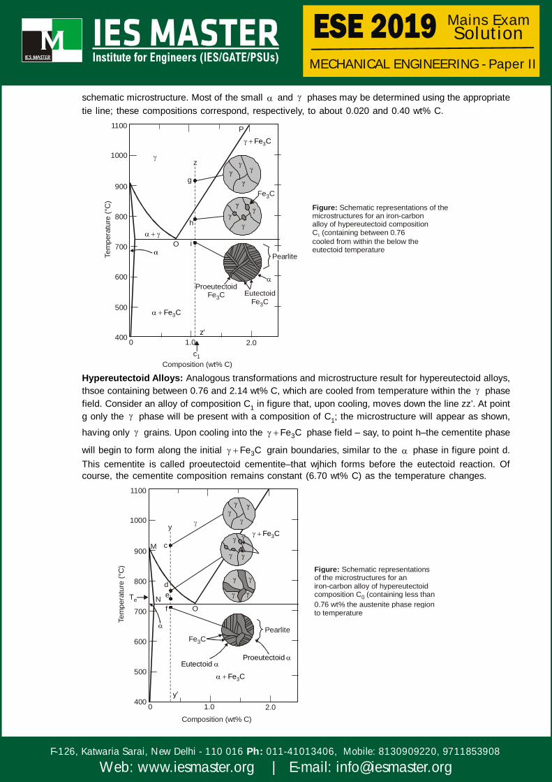
schematic microstructure. Most of the small and phases may be determined using the appropriatetie line; these compositions correspond, respectively, to about 0.020 and 0.40 wt% C.
P1100
1000
900
800
700
600
500
400 0 1.0c1
Composition (wt% C)
2.0z
3Fe C
Eutectoid Fe C3
Proeutectoid Fe C3
Pearlite
O i
Tem
pera
ture
(°C
)
z
g
h
3Fe C
Fe C3
Figure: Schematic representations of themicrostructures for an iron-carbonalloy of hypereutectoid compositionC (containing between 0.76 cooled from within the below theeutectoid temperature
1
Hypereutectoid Alloys: Analogous transformations and microstructure result for hypereutectoid alloys,thsoe containing between 0.76 and 2.14 wt% C, which are cooled from temperature within the phasefield. Consider an alloy of composition C1 in figure that, upon cooling, moves down the line zz’. At pointg only the phase will be present with a composition of C1; the microstructure will appear as shown,
having only grains. Upon cooling into the 3Fe C phase field – say, to point h–the cementite phase
will begin to form along the initial 3Fe C grain boundaries, similar to the phase in figure point d.This cementite is called proeutectoid cementite–that wjhich forms before the eutectoid reaction. Ofcourse, the cementite composition remains constant (6.70 wt% C) as the temperature changes.
1100
1000
900
800
700
600
500
4000 1.0
Composition (wt% C)2.0
3Fe C
O
Tem
pera
ture
(°C
)
Eutectoid
Fe C3
Pearlite
Proeutectoid
y
fN e
d
cM3Fe C
y
Te
Figure: Schematic representationsof the microstructures for aniron-carbon alloy of hypereutectoidcomposition C (containing less than0.76 wt% the austenite phase regionto temperature
0
MECHANICAL ENGINEERING - Paper II
F-126, Katwaria Sarai, New Delhi - 110 016 011-41013406, Mobile: 8130909220, 9711853908Ph:
Web: www.iesmaster.org | E-mail: [email protected]
Mains Exam Solution
Q.6: (c) (i) Describe, with neat sketches, the working principle of—(1) linear variable differential transformer (LVDT);(2) Hall effect sensor [5+5 Marks]
(ii) A measurement system consists of a cylindrical load cell of diameter 2.5 mm. Thematerial of the cell is steel with modulus of elasticity, E = 210 GPa and Poisson’s ratio, = 0.3. This carries four strain gauges each with gauge factor 2.1. Two of them aremounted longitudinal and other two are transverse. The resistances of the gauges are
120 . This load cell is required to yield a voltage through the bridge of strain gaugeswith bias 10V. If the maximum load sustained by the cell is –2500 N, what is thecorresponding voltage across the bridge? [10 Marks]
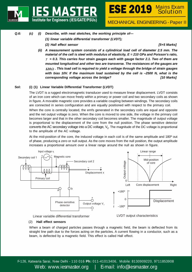
Sol: (i) (1) Linear Variable Differential Transformer (LVDT)The LVDT is a rugged electromagnetic transducer used to measure linear displacement. LVDT consistsof an iron core which can move freely within a primary or power coil and two secondary coils as shownin figure. A movable magnetic core provides a variable coupling between windings. The secondary coilsare connected in series configuration and are equally positioned with respect to the primary coil.When the core is centrally located, the emfs generated in the secondary coils are equal and oppositeand the net output voltage is zero. When the core is moved to one side, the voltage in the primary coilbecomes larger and that in the other secondary coil becomes smaller. The magnitude of output voltageis proportional to the displacement of the core from the null position. The phase sensitive detectorconverts the AC secondary voltage into a DC voltage, V0. The magnitude of the DC voltage is proportionalto the amplitude of the AC voltage.
At the mid-position of the core, the induced voltage in each coil is of the same amplitude and 180º outof phase, producing a zero or null output. As the core moves from the null position, the output amplitudeincreases a proportional amount over a linear range around the null as shown in figure.
Secondary coil 2
Displacement x
Output voltage VoPhase-sensitive
detector
Primary coil
+ –
+ –
+
–
a b
Linear variable differential transformer
Linear range
Mid-positionof core
0Left Core displacement Right
+180º
0
–180ºf
Out
put v
olta
ge
LVDT output characteristics
Displacement
(2) Hall effect sensorsWhen a beam of charged particles passes through a magnetic field, the beam is deflected from itsstraight line path due to the forces acting on the particles. A current flowing in a conductor, such as abeam, is deflected by a magnetic field. This effect is called Hall effect.


MECHANICAL ENGINEERING - Paper II
F-126, Katwaria Sarai, New Delhi - 110 016 011-41013406, Mobile: 8130909220, 9711853908Ph:
Web: www.iesmaster.org | E-mail: [email protected]
Mains Exam Solution
Vi R
t1
3
Hallstrip
Outputvoltage
ATransverse
magnetic field
Fig. Hall effect sensor
2
The working principle of a Hall effect sensor is that if a strip of conducting material carries a currentin the presence of a transverse magnetic field as shown in Fig., the difference of potential is producebetween the opposite edges of the conductor. The magnitude of the voltage depends upon the currentand the magnetic field. The current is passed through leads 1 and 2 of the strip and the output leads3 and 4 are connecred with a Hall strip. When a transverse magnetic field passes through the strip, thevoltage difference occurs in the output leads. The Hall effect sensor has the advantage of being ableto operate as a switch and it can operate upto 100 kHz.
(ii) Given, diameter of load cell, d = 2.5 mm
E = 210 GPa, Poisson’s ratio, 0.3
Gauge factor, Gf = 2.1
Resistance of each gauge, gR 120
Supply voltage, Vi = 10V
Load applied, F = 2500 N (Compressive)
stress =load
cross-sectional area
=
8 2
2
2500 5.093 10 N/m0.00254
strain =stress
modulus of elasticity
=8
39
5.093 10 2.425 10210 10
fractional change in resistance,
dRR
= 3fG 2.1 2.425 10
= 5.093 × 10⁻³
The output voltage of bridge using four strain gauges mounted at 90°
V0 = iif
VVdR2 2 G1 14R 4

MECHANICAL ENGINEERING - Paper II
F-126, Katwaria Sarai, New Delhi - 110 016 011-41013406, Mobile: 8130909220, 9711853908Ph:
Web: www.iesmaster.org | E-mail: [email protected]
Mains Exam Solution
= 32 1 0.3 5.093 10 10 / 4
= 0.033 volt
Q.7: (a) (i) On the basis of microstructure, briefly explain why gray iron is brittle and weak intension. Compare gray and malleable cast irons with respect to (1) composition andheat treatment, (2) microstructure and (3) mechanical properties. [10 Marks]
(ii) Cite three sources of internal residual stresses in metal components. What are twopossible adverse consequences of these stresses? Describe the following heattreatment procedures for steels and for each, the intended final microstructure:Full annealing, Normalizing, Tempering and Quenching
[10 Marks]
Sol. (i) Mechanically, gray iron is comparatively weak and brittle in tension as a consequence of itsmicrostructure; the tips of the graphite flakes are sharp and pointed, and may serve as points ofstress concentration when an external tensile stress is applied. Strength and ductility are muchhigher under compressive loads.
This question asks us to compare various aspects of gray and mellable cast irons.(a) With respect to composition and heat treatment :Gray iron - 2.5 to 4.0 wt% C and 1.0 to 3.0 wt%. For mass gray irons there is no heat treatment aftersolidification.Malleable iron - 2.5 to 4.0 wt% C and less than 1.0 wt% St. White iron is heated in a nonoxidizingatmosphere and a temperature between 800 and 900°C for an extended item period.(b) With respect to microstructure :
Gray iron-Graphite flakes are embedded in a ferrite or pearlite matrix.Malleable iron - Graphite clusters are embedded in a ferrite or pearlite matrix.
(c) With respect to mechanical characteristics :Gray iron - Relatively weak and brittle in tension; good capacity for damping vibrations,Melleable iron - Moderate strength and ductility.
(ii) Three sources of internal residual stresses in metal components are :1. Plastic deformation process such as machining and grinding2. Nonuniform cooling of a piece that was cold from an elevated temperature such as in casting or
welding.3. Phase transformation that is induced upon cooling in which parent and product phases have
different densities.Two adverse consequences of these stresses are distortion, crack formation and fracture.
Full annealing: Heat to about 50°C above the A3 line, figure 11.10 (fi the concentration ofcarbon is less than the eutectoid) or above A1 line (if the concentration of carbon is greaterthan the eutectoid) until the alloy comes to equilibriums, then furnace cool to roomtemperature. The final microstructure is coarse parlit.Normalizing: Heat to at least 55°C above the A3 line Figure 11.10 (if the concentration of carbonis less than the eutectoid) or above the Acm line (if the concentration pf carbon is greater than theeutectoid) until the alloy completely transform to austenite, then the cool in air. The finalmicrostructure is file perlite.Ouenching: Het to a temperature with the austentite phase region and alloy the specimen to fullyaustenitize, the quench to room temperature in over water. The final microstructure is martensite.

MECHANICAL ENGINEERING - Paper II
F-126, Katwaria Sarai, New Delhi - 110 016 011-41013406, Mobile: 8130909220, 9711853908Ph:
Web: www.iesmaster.org | E-mail: [email protected]
Mains Exam Solution
Tempering: Heat is quenched (martensite) specimen to a temperature between 450 and 650°C,the for time necessary to achieve the desired hardness. The final microstructure is temperedmartensite.
Q.7: (b) (i) Why is unilateral tolerance preferred over bilateral tolerance? Find the limits of toleranceand allowance for a 25 mm H8d9 shaft and hole pair. The 25 mm shaft lies in the18–30 diameter step. The fundamental tolerance can be computed usingi = 30.45 D 0.001D m . For H8 hole, the fundamental tolerance is 40i. The fundamentaldeviation for the shaft can be computed using –16D0.44 m . What type of fit is givenby H8d9?List the causes of getting primary texture and secondary texture in machinedcomponents. Further, list the three main methods of assessment of surface texture.
[10 Marks](ii) Five jobs are to be processed on three machines. The processing time (in hours) is
given in the following table. Find the optimal schedule so that the total elapsed timeis minimized. Also, find the idle time on each machine: [10 Marks]
M1
M2
M3
8 10 6 7 11
5 6 2 3 4
4 9 8 6 5
J1 J2 J3 J4 J5
Jobs
Machines
Sol: (i)Unilateral tolerance is preferred over bilateral tolerance because of the following reasons:
(a) It is easy and simpler to determine deviations in unilateral tolerance.
(b) Provides flexibility to operator as he has to maintain only lower limit of holes knowing fully thathe still has some margin left for machining before the part is rejected.
Given, 25 H8d9
Basic size = 25mm
Mean dia (D) = 18 30
= 23.24 mm
Tolerance factor (i) = 0.45 D1/3 + 0.001 D
= 0.45 (23.24)1/3 + 0.001 × 23.24
= 1.307 microns
For hole, H fundamental deviation is zero
Fundamental tolerance (1T8),
= 25i
= 25 × 1.307
= 32.675 microns
0.033 mm


MECHANICAL ENGINEERING - Paper II
F-126, Katwaria Sarai, New Delhi - 110 016 011-41013406, Mobile: 8130909220, 9711853908Ph:
Web: www.iesmaster.org | E-mail: [email protected]
Mains Exam Solution
For shaft f, fundamental deviation = – 16 D0.44
= –16(23.24)0.44
= – 63.85 microns
= – 0.064 mm
Fundamental tolerance for shaft (IT 9)
= 40i
= 40 × 1.307
= 52.28 microns
= 0.052 mm
For hole,
Upper or high limit = Basic size + Tolerance
= 25 + 0.033
= 25.033 mm
Lower or Low limit = Basic size + 0 = 25 mm
0.0330.00025 mm
For shaft, upper or high limit = Basic size - Fundamental deviation
= 25 – 0.064
= 24.936 mm
Lower or low limit = Basic size – fundamental deviation – tolerance
= 25 – 0.064 – 0.052
= 24.884
0.0640.01625
ShaftHol
e
25m
0.033mm0.064mm
24.884mm24.936mm
Datum Line
Zero Line
The figure clearly indicates that the given fit is clearance fit with.
Min (c) = LL of hole – UL of shaft
= 25 – 24.936 = 0.064 mm
Max (c) = UL of hole – LL of shaft
= 25.033 – 24.884 = 0.149 mm
A single-point tool turning a bar. The metal is cut from A to B and from C to D, but the element D toE is a torn surface created when the tool’s end cutting-edge passes through the wall left on the previousrevolution by its side cutting-edge. Further, in some machining processes the action of the nose fromB to C can be more akin to burnishing than cutting.

MECHANICAL ENGINEERING - Paper II
F-126, Katwaria Sarai, New Delhi - 110 016 011-41013406, Mobile: 8130909220, 9711853908Ph:
Web: www.iesmaster.org | E-mail: [email protected]
Mains Exam Solution
Thus the roughness on surfaces produced by single point cutting tends to be both uniformly spaced anddirectional.
Roughness(Primary texture)
Waviness(Secondary texture)
Roughnessspacing
Wavinessspacing
Profile
Elements of surface character ofa machined surface
Lay(Direction of dominantpattern)
Reasons for(i) Primary texture Roughness: Small wavelength scratches or tool marks produced by cutting
tools or during other production processes(ii) Secondary texture (Waviness): Spindle or cutter deflection, machine vibrations, chatter, hard
sports, impertect truing of a grinding wheel etc.Three main methods to assessment of surface texture:(i) Optical method using light interference microscopes(ii) Stylus method using electrical integration.(iii) Tactile (Finger nail) surface assessment method.(ii)
1 2 3
1
2
3
4
5
Jobs M M M
J 8 5 4
J 10 6 9
J 6 2 8
J 7 3 6
J 11 4 5
This sequencing problem involves three machines and minimum time on machine M1 maximumtime on machine M2 or minimum time on machine M3 Maximum time on machine M2
Hence, the above problem can be converted into an equivalent two machine problem by two fictionsmachines G and H, such thatG = M1 + M2 and H = M2 + M3
1
2
3
4
5
Jobs G H
J 13 9
J 16 15
J 8 10
J 10 9
J 15 9
MECHANICAL ENGINEERING - Paper II
F-126, Katwaria Sarai, New Delhi - 110 016 011-41013406, Mobile: 8130909220, 9711853908Ph:
Web: www.iesmaster.org | E-mail: [email protected]
Mains Exam Solution
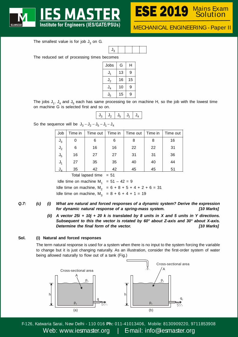
The smallest value is for job J3 on G.
3J
The reduced set of processing times becomes
1
2
4
5
Jobs G H
J 13 9
J 16 15
J 10 9
J 15 9
The jobs J1, J4 and J5 each has same processing tie on machine H, so the job with the lowest timeon machine G is selected first and so on.
3 2 5 1 4J J J J J
So the sequence will be 3 2 5 1 4J J J J J
3
2
5
1
4
Job Time in Time out Time in Time out Time in Time out
J 0 6 6 8 8 16
J 6 16 16 22 22 31
J 16 27 27 31 31 36
J 27 35 35 40 40 44
J 35 42 42 45 45 51Total lapsed time = 51
Idle time on machine M1 = 51 – 42 = 9Idle time on machine, M2 = 6 + 8 + 5 + 4 + 2 + 6 = 31Idle time on machine, M3 = 8 + 6 + 4 + 1 = 19
Q.7: (c) (i) What are natural and forced responses of a dynamic system? Derive the expressionfor dynamic natural response of a spring-mass system. [10 Marks]
(ii) A vector 25i + 10j + 20 k is translated by 8 units in X and 5 units in Y directions.Subsequent to this the vector is rotated by 60° about Z-axis and 30° about X-axis.Determine the final form of the vector. [10 Marks]
Sol. (i) Natural and forced responsesThe term natural response is used for a system when there is no input to the system forcing the variableto change but it is just changing naturally. As an illustration, consider the first-order system of waterbeing allowed naturally to flow out of a tank (Fig.)
h
Ap1
p2
Cross-sectional area
(a)
qh
A
p1
p2
Cross-sectional area
(b)
q2


MECHANICAL ENGINEERING - Paper II
F-126, Katwaria Sarai, New Delhi - 110 016 011-41013406, Mobile: 8130909220, 9711853908Ph:
Web: www.iesmaster.org | E-mail: [email protected]
Mains Exam Solution
For such a system we have
p1 – p2 = Rq
where R is the hydraulic resistance. But p1 – p2 = h g , where is the density of the water, and q is
the rate at which water leaves the tank and so is dVdt
, with V being the volume of water in the tank
and so being Ah. Thus q = d(Ah)dt
=
Adhdt
and so the above equation can be written as
h g =dhRAdt
This is the natural response in that there is no input to the system forcing the variable h to change; itis just naturally changing with time. We can draw attention to this by writing the differential equation withall the output terms, i.e. h, on the same side of the equals sign and the input term of zero on the right,i.e.
dhRA ( g)hdt
= 0
In the differential equation was derived for a water tank from which water was flowing but also into whichthere was a flow of water (Fig.) This equation has a forcing input function of q1 and can be written as
dhRA ( g)hdt
= q1
As another example, consider a thermometer being placed in a hot liquid at some temperature TL. Therate at which the reading of the thermometer T changes with time was derived in as being given by thedifferential equation
dTRC Tdt
= TL
Such a differential equation has a forcing input of TL.
Natural Response of a Spring Mass System (First Order System) :The input y(t) can take many forms. Consider first the situation when the input is zero. Because thereis no input to the system we have no signal forcing the system to respond in any way other than itsnatural response with no input. The differential equation is then.
1 0dxa a xdt
= 0
When can solve this equation by using the technique called separation of variables. The equation canbe written with all the x variables on one side and all the t variables on the other.
dxx
=0
1
adt
a
Integrating this between the initial value of x = 1 at t = 0, i.e. a unit steip input, and x at t gives
lnx =0
1
at
a
and so we have,
x = 0 1a t/ae

MECHANICAL ENGINEERING - Paper II
F-126, Katwaria Sarai, New Delhi - 110 016 011-41013406, Mobile: 8130909220, 9711853908Ph:
Web: www.iesmaster.org | E-mail: [email protected]
Mains Exam Solution
We could however, have recognised that the differential equation would have a solution of the forms x= Aest, where A and s are constants. We then have dx/dt = sAest and so when these values aresubstituted in the differential equation we obtain.
a1sAest + a0Aest = 0
and so a1s + a0 = 0 and s = –a0/a1. Thus the solution is
x = 0 1a t/aAe
This is termed the natural response since there is no forcing function. We can determine the value ofthe constant A given some initial (boundary) condition. Thus if x = 1 when t = 0 then A = 1. Shown infigure, the natural response, i.e. an exponential decay:
Systemy(t)
Zeroinput
x(t)
1
Time0
Out
put,
x
Fig. Natural response of a first order system
(ii) Homogeneous transformatix after successive translations and rotations :
[T] = rz rxtr 60 30T TT
[T] =
1 0 0 8 cos60 sin60 0 0 1 0 0 0
0 1 0 5 sin60 cos60 0 0 0 cos30 sin30 0
0 0 1 0 0 0 1 0 0 sin30 cos30 0
0 0 0 1 0 0 0 1 0 0 0 1
=
cos 60 sin 60 0 8 1 0 0 0sin 60 cos 60 0 5 0 cos30 sin30 0
0 0 1 0 0 sin30 cos30 00 0 0 1 0 0 0 1
=
cos60 sin60 cos30 sin60 sin30 8
sin60 cos60 cos30 cos60 sin30 5
0 sin30 cos30 0
0 0 0 1

MECHANICAL ENGINEERING - Paper II
F-126, Katwaria Sarai, New Delhi - 110 016 011-41013406, Mobile: 8130909220, 9711853908Ph:
Web: www.iesmaster.org | E-mail: [email protected]
Mains Exam Solution
=
1 3 3 3 1 82 2 2 2 2
3 1 3 1 1 52 2 2 2 2
1 30 02 2
0 0 0 1
T X =
1 3 3 82 4 4 253 3 1 105
2 4 420
1 30 0 12 20 0 0 1
=
25 30 3 20 82 4 4
25 3 203 10 52 4 4
10 30 20 02 20 0 0 1
=
21.66
25.98
22.32
1
Final form of vector = ˆ ˆ ˆ21.66i 25.98 j 22.32k
Q.8: (a) (i) Explain briefly the following: [10 Marks](1) Four configurations of Robot(2) Work volume(3) Spatial resolution(4) Accuracy(5) Repeatability
(ii) A 4 d-o-f manipulator of Maker Robot type is shown in the figure given below. Preparea D-H parameter table for this configuration. Define the position of end wrist P interms of joint lengths and angles: [10 Marks]

MECHANICAL ENGINEERING - Paper II
F-126, Katwaria Sarai, New Delhi - 110 016 011-41013406, Mobile: 8130909220, 9711853908Ph:
Web: www.iesmaster.org | E-mail: [email protected]
Mains Exam Solution
x
y
J1
z
J2
J4
J3
d3
1 (about z-axis)
2 (about x-axis) 4 (about x-axis)
P(x, y, z)
P4(x , y , z )4 4 4
Sol: (i)(1) Four configurations of RobotVarious types of robot configuration based on work space are
(a) Cartesian Configuration
(b) Spherical or polar Configuration
(c) Cylindrical Configuration
(d) Articulated Configuration
y
x
z(a) Cartesian Configuration
(c) Cylindrical Arm configuration
y
z
(b) Spherical Arm Configuration
z
y
(d) Articulated Arm Configuration
O

MECHANICAL ENGINEERING - Paper II
F-126, Katwaria Sarai, New Delhi - 110 016 011-41013406, Mobile: 8130909220, 9711853908Ph:
Web: www.iesmaster.org | E-mail: [email protected]
Mains Exam Solution
(2) Work volume: It is a spatial region within which the end of the robot’s wrist can be manipulated.Work volume is determined by,
Physical configuration. Size of joints and links. Number of axes. The robot mounted position (over head gantry, wall mounted, floor mounted) Limits of arm and joint configurations. The addition of an end - effector can move or offset the entire work volume.(3) Spatial resolution
Spatial Resolution: Smallest increment of motion / movement of the wrist or end effector (tool)end that can be controlled by the robot. Depends on the position control system, feedbackmeasurement, and mechanical accuracy.
(Target point)
Accuracy
Spatial Resolution
One possibleposition An Adjacent position A + 1n
Robot wrist end
Control Resolution 3
3
Normal distribution ofmechanical inaccuracies
Robot wrist end
(4) Accuracy:Accuracy: Capability to position the wrist at a target point in the work volume. It is halfof the distance between two adjacent resolution points. It is affected by mechanical inaccuracies.
Manufactures don’t provide the accuracy (hard to control).
Refer to figure shown the following definition can be established :
Accuracy =Control resolution 3
2
Where, = Standard deviation of mechanical error
Repeatability = 3 6
Spatial resolution = Control resolution + 6
Accuracy, in terms of spatial resolution = Spatial resolution
2(5) Repeatability: Ability to position back to a point that was previously taught. Repeatability errors
from random variable mechanical accuries in arm, wrist components. Larger robots have lessprecise repeatability values.
Repeatability
Actual pointachieved
Target point 'T'Repeatedpoint 'R'
R
A
Previous position

MECHANICAL ENGINEERING - Paper II
F-126, Katwaria Sarai, New Delhi - 110 016 011-41013406, Mobile: 8130909220, 9711853908Ph:
Web: www.iesmaster.org | E-mail: [email protected]
Mains Exam Solution
(ii)
Y1X1
Z1
Y2X2
Z2
Y3X3
Z3
YPXP
ZP
Z0Y0
x0
L1
[0]
[1]
1
2
L2
[2]
4
[3] [4]
d3 L4
Joint Variable (4 DOF)
1 2 3 4, , d ,
i i i i
1 1
2 2
3
4 4
D H Parameter TableFrame a d
0 1 0 90 L 90
1 2 0 L 0
2 3 0 0 d 0
3 4 0 L 0
i 1iT =
i i i i i i i
i i i i i i i
i i i
C S C S S a C
S C C C S a S
0 S C d
0 0 0 1
01T =
1 1
1 1
1
cos 0 sin 090 90
sin 0 cos 090 90
0 1 0 L
0 0 0 1
01T =
1 1
1 1
1
S 0 C 0
C 0 S 0
0 1 0 L
0 0 0 1
12T =
2 2
2 2 2
1 0 0 0
0 C S 0
0 S C L
0 0 0 0
23T = 3
1 0 0 0
0 1 0 0
0 0 1 d
0 0 0 1

MECHANICAL ENGINEERING - Paper II
F-126, Katwaria Sarai, New Delhi - 110 016 011-41013406, Mobile: 8130909220, 9711853908Ph:
Web: www.iesmaster.org | E-mail: [email protected]
Mains Exam Solution
34T =
4 4
4 4 4
1 0 0 0
0 C S 0
0 S C L
0 0 0 1
04T = 0 1 2 3
1 2 2 4T T T T
Q.8: (b) (i) Draw the “bathtub curve” and indicate various failure regions. List the major causesof failure in mechanical components/system. Draw the flowchart for failure modes andeffects analysis (FMEA). [10 Marks]
(ii) Explain the mechanism of metal removal in die-sinking EDM. State the three mainadvantages of electron-beam machining (EBM).
[10 Marks]
Sol. (i)
Constant failure rateor
useful life period
Wearoutperiod
Infantmortalityperiod
Haz
ard
rate
h(t)
Age or life (hours, cycles, km, etc.)0 t 1 t2
Fig. Idealized bathtub hazard rate curveIn general, the failure of mechanical parts can occur due to variety of reasons. Some of the mostcommon failure modes for a mechanical component are mentioned below.(a) Ductile and Brittle failure
(b) Fatigue that includes high-cycle and low-cycle fatigue, thermal fatigue, surface fatigue, impactfatigue, corrosion fatigue and fretting fatigue.
(c) Corrosion due to direct chemical attack, galvanic corrosion, crevice and pitting corrosion,intergranular corrosion, selective leaching, biological corrosion, stress corrosion, corrosion dueto erosion, hydrogen induced corrosion, etc.
(d) Wear [adhesive wear, abrasive wear, corrosive wear, wear due to deformation, imapct frettingand surface fatigue]
(e) Impact [deformation, wear and fracture due to impact, impact fretting and fatigue]
(f) Fretting [fatigue, wear and corrosion due to fatigue]
(g) Galling and seizure
(h) Creep related failure, combined creep and fatigue
(i) Thermal shock and thermal relaxation
(j) Buckling due to static or dynamic load or due to creep
(k) Localized oxidation
(l) Radiation damage
(m) Bonding failure and / or delamination
(n) Erosion

MECHANICAL ENGINEERING - Paper II
F-126, Katwaria Sarai, New Delhi - 110 016 011-41013406, Mobile: 8130909220, 9711853908Ph:
Web: www.iesmaster.org | E-mail: [email protected]
Mains Exam Solution
Initiate FMEA of an item
Select a component of the item to analyze
Identify failure modes of the selected component
Select the failure mode to analyze
Identify effect of the failure mode
Determine severity of the final effect
Identify potential causes of that failure mode
Estimate frequency or probability of occurence for the failure mode during the predetermined
time period
Are theremore failure modes
to analyze?
Are thereother components for
analysis?
Complete FMEA
No
Yes Yes
No
Flow chart for FMEA(ii) Die-Sinker EDM is known by different names such as Ram EDM, sinker EDM, vertical EDM andplunge EDM. The process is generally used for producing blind cavities. In die-sinker EDM, the electrodeand workpiece are submerged in an insulating liquid such as oil or other dielectric fluids. The electrodeand workpiece are connected to a suitable power supply. An electrical potential is generated betweenthe tool and the workpiece through the power supply. As the electrode approaches workpiece, thedielectric break down starts taking place in the fluid. Due to this activity, a plasma channel starts formingand sparks jump from the electrode to the workpiece leading to material removal from the workpiece.
Electrode
Workpiece
Advantages of EBM:EBM provides very high drilling rates when small holes with large aspect ratio are to be drilled.Moreover it can machine almost any material irrespective of their mechanical properties. As it appliesno mechanical cutting force, work holding and fixturing cost is very less. Further for the same reasonfragile and brittle materials can be processed. The heat affected zone in EBM is rather less due toshorter pulses. EBM can provide holes of any shape by combining beam deflection using electromagneticcoils and the CNC table with high accuracy.

MECHANICAL ENGINEERING - Paper II
F-126, Katwaria Sarai, New Delhi - 110 016 011-41013406, Mobile: 8130909220, 9711853908Ph:
Web: www.iesmaster.org | E-mail: [email protected]
Mains Exam Solution
Q.8: (c) A manufacturer of patient medicines is proposed to prepare a production plan for medicinesA and B. There are sufficient ingredients available to make 20000 bottles of medicine A and40000 bottles of medicine B. However, there are only 45000 bottles into which either of themedicines can be filled. Further, it takes three hours to prepare enough material to fill 1000bottles of medicine A and one hour to prepare enough material to fill 1000 bottles ofmedicine B, and there are 66 hours available for this operation. The profit is ` 8 per bottlefor medicine A and ` 7 per bottle for medicine B.
(i) Formulate this problem as linear programming problem.(ii) How does the manufacturer schedule his production in order to maximize profit? Use
graphical method. [20 Marks]
Sol. Let x, be the bottles for medicine A and x2 be the bottles for medicine B.
Than, 1 2x x 45000 or 1 2x x 145000 45000
...(i)
1 23x x1000 1000
66
1 2x x22000 66000
1 ...(ii)
1x 20000 and 2x 40000 ....(iii)
x1, x2 0Maximise Z = 8x1 + 7x2
(0,66000)
(0,45000)
(0,40000)C
A
D
(10500,34500)E
(20,000,0) (45000,0)
B
x2
(5000, 40000)(10500, 34500)
(20000, 6000)
(22000, 0)
At Point A
Z = 8 × 20000 = ` 160000At point C
Z = 7 × 40000 = ` 280000
At point B
Z = 8 × 10500 + 7 × 34500 = ` 325500
At point D
Z = 8 × 20000 + 7 × 6000 = ` 202000
At point E
Z = 8 × 5000 + 7 × 40000 = ` 320000
Hence, the value of Z will be maximum at B (10500, 34500)
Zmax = ` 325500