mechanical equipment and subsystems integrity program
TRANSCRIPT
MIL-HDBK-1798A24 September 2001SUPERSEDINGMIL-HDBK-1798 (USAF)19 December 1997
DEPARTMENT OF DEFENSEHANDBOOK
MECHANICAL EQUIPMENT ANDSUBSYSTEMS INTEGRITY PROGRAM
This handbook is for guidance only.
Do not cite this document as a requirement.
AMSC N/A AREA SESS
DISTRIBUTION STATEMENT A. Approved for public release; distribution is unlimited.
NOTMEASUREMENT
SENSITIVE
Downloaded from http://www.everyspec.com
MIL-HDBK-1798A
ii
FOREWORD
1. This handbook is approved for use by the Department of the Air Force and is available foruse by all Departments and Agencies of the Department of Defense.
2. This handbook is for guidance only. This handbook cannot be cited as a requirement. If itis, the contractor does not have to comply.
3. This handbook establishes programmatic tasks for the development, acquisition,modification, operation, and sustainment of the mechanical elements of airborne, support, andtraining systems. The Mechanical Equipment and Subsystems Integrity Program (MECSIP)consists of a series of disciplined, time-phased actions which, when applied in accordance withthis handbook, will help ensure the continued operational safety, suitability, and effectiveness ofthe mechanical systems throughout all phases of the weapon system life.
4. Beneficial comments (recommendations, additions, deletions) and any pertinent data whichmay be of use in improving this document should be addressed to: ASC/ENOI, 2530 LOOPROAD WEST, WRIGHT-PATTERSON AFB OH 45433-7101; by using the StandardizationDocument Improvement Proposal (DD Form 1426) appearing at the end of this document, or aletter.
Downloaded from http://www.everyspec.com
MIL-HDBK-1798A
iii
CONTENTSParagraph Page1. SCOPE.............................................................................................................. 11.1 Purpose ............................................................................................................. 11.2 Use .................................................................................................................... 11.2.1 Structure............................................................................................................ 11.3 Program approach............................................................................................. 11.4 Program overview.............................................................................................. 21.5 Applicability ....................................................................................................... 22. APPLICABLE DOCUMENTS ............................................................................ 32.1 General.............................................................................................................. 32.2 Government documents .................................................................................... 32.2.1 Specifications, standards, and handbooks........................................................ 32.2.2 Other Government documents, drawings, and publications.............................. 32.3 Order of precedence ......................................................................................... 33. DEFINITIONS.................................................................................................... 43.1 Analysis ............................................................................................................. 43.2 Damage tolerance ............................................................................................. 43.3 Demonstration ................................................................................................... 43.4 Durability ........................................................................................................... 43.5 Durability-critical component ............................................................................. 43.6 Durability-noncritical component ....................................................................... 43.7 Economic life ..................................................................................................... 43.8 Inspection .......................................................................................................... 43.9 Integrity.............................................................................................................. 43.10 Maintenance-free operating period ................................................................... 53.11 Mission-critical component ................................................................................ 53.12 Other/expendable components ......................................................................... 53.13 Required operational service life ....................................................................... 53.14 Required operational service period.................................................................. 53.15 Safety-critical component .................................................................................. 53.16 Test ................................................................................................................... 53.17 Usage ................................................................................................................ 54. REQUIREMENTS.............................................................................................. 54.1 Mechanical Equipment and Subsystems Integrity Program (MECSIP)............. 54.1.1 Tailoring approach............................................................................................. 64.1.2 Implementing Statement of Work ...................................................................... 74.2 (Task I) Preliminary planning............................................................................. 74.2.1 Program strategy............................................................................................... 74.2.2 Trade studies..................................................................................................... 74.2.3 Development of requirements ........................................................................... 74.2.4 Preliminary integrity analysis ............................................................................. 74.3 (Task II) Design information .............................................................................. 84.3.1 MECSIP master plan......................................................................................... 84.3.2 Design criteria ................................................................................................... 94.3.3 Design service life/design usage....................................................................... 94.3.4 Critical parts analysis and classification ............................................................ 94.3.5 Material and process selection and characterization ........................................ 104.3.6 Product integrity control plan............................................................................. 104.3.7 Corrosion prevention and control ...................................................................... 11
Downloaded from http://www.everyspec.com
MIL-HDBK-1798A
iv
Paragraph Page4.4 (Task III) Design analyses and development tests............................................ 114.4.1 Design analyses ................................................................................................ 114.4.1.1 Load definition ................................................................................................... 114.4.1.2 Design stress/environment spectra development.............................................. 114.4.1.3 Performance and function sizing analyses........................................................ 114.4.1.4 Thermal/environmental analyses....................................................................... 114.4.1.5 Stress/strength analyses ................................................................................... 124.4.1.6 Durability analyses ............................................................................................ 124.4.1.7 Damage tolerance analyses.............................................................................. 124.4.1.8 Vibration/dynamics/acoustic analyses............................................................... 124.4.2 Development tests............................................................................................. 134.4.2.1 Material characterization tests........................................................................... 134.4.2.2 Design development tests ................................................................................. 134.5 (Task IV) Component development and systems functional tests..................... 134.5.1 Functional tests ................................................................................................. 134.5.2 Strength testing ................................................................................................. 144.5.3 Durability testing................................................................................................ 144.5.4 Vibration/dynamics/acoustics tests ................................................................... 144.5.5 Damage tolerance tests .................................................................................... 144.5.6 Thermal and environment survey ...................................................................... 154.5.7 Maintainability/reparability demonstrations ....................................................... 154.5.8 Evaluation and interpretation of test results ...................................................... 154.5.9 Integrated test plan............................................................................................ 154.5.10 Final integrity analysis. ...................................................................................... 154.5.11 Maintenance planning and task development ................................................... 164.6 (Task V) Force management............................................................................. 164.6.1 Component tracking/monitoring program .......................................................... 164.6.1.1 Operational usage data ..................................................................................... 164.6.2 Preventative maintenance actions .................................................................... 164.6.2.1 Flight-hour time change..................................................................................... 174.6.2.2 Calendar time change ....................................................................................... 174.6.2.3 On-equipment repairs........................................................................................ 174.6.2.4 Lubrication/cleaning and adjustments ............................................................... 174.6.2.5 Overhaul of systems.......................................................................................... 174.6.2.6 Replacement of original equipment................................................................... 184.6.2.7 Replacement of obsolete equipment................................................................. 184.6.2.8 Environmental regulations................................................................................. 184.6.3 Monitoring of repairs/overhauls ......................................................................... 184.6.3.1 Field/base-level maintenance............................................................................ 194.6.3.2 Depot-level maintenance................................................................................... 194.6.4 Inspection criteria .............................................................................................. 194.6.4.1 Damage-tolerance-critical components............................................................. 195. NOTES .............................................................................................................. 205.1 Intended use...................................................................................................... 205.2 Data requirements............................................................................................. 205.3 Subject term (key word) listing .......................................................................... 205.4 Responsible engineering office ......................................................................... 215.5 Changes from previous issue............................................................................ 21
Downloaded from http://www.everyspec.com
MIL-HDBK-1798A
1
1. SCOPE
1.1 Purpose. The purpose of this handbook is to describe the general process to achieve andmaintain the physical and functional integrity of the mechanical elements of airborne, support,and training systems. The goal of the program is to ensure the operational safety, suitability,and effectiveness (OSS&E) of a weapon system, while reducing total operating cost. Theprocess described herein is in direct support of the OSS&E Air Force Policy Directive 63-12 andthe Air Force Instruction 63-1201 requirements to establish a disciplined engineering processthat will ensure the physical and functional integrity of the system being procured. Thishandbook allows the process to be tailored in a competitive environment to meet specificequipment, subsystem, and/or system requirements. The Mechanical Equipment andSubsystems Integrity Program (MECSIP) is implemented in the planning process and continueduntil retirement of the system. This handbook should be tailored for each program inaccordance with specific program strategy.
The process described herein is a “cradle-to-grave” process that is equally applicable to thedesign phase as it is to the sustainment phase. It applies to new development, modifications,upgrades, and sustainment. It applies equally to both development and non-developmentitems, including commercial off-the-shelf. For development items, the purpose of this process isto establish and sustain a design that meets the service life, mission, usage, and environmentalrequirements. For non-development items, the emphasis is on definition of the capabilities ofthe item when subjected to the intended service life, mission, usage and environments. Ifshortfalls are identified in the existing capabilities of a non-development item, the SystemProgram Office then has the necessary information to initiate the appropriate trades relative tothe cost of the design change versus required performance, maintenance actions, totaloperating cost, impact on mission, etc.
1.2 Use. This handbook cannot be used for contractual purposes until it is tailored withspecific supplemental information pertinent to the equipment or system being procured. Theinformation from this handbook is intended for inclusion in the Request for Proposal (RFP) andcontract Statement of Work (SOW). Once the system is fielded, the MECSIP manager shouldtailor an appropriate integrity program based on the information contained in this handbook andthe integrity program established during the development phase. This handbook is for guidanceonly. This handbook cannot be cited as a requirement. If it is, the contractor does not have tocomply.
1.2.1 Structure. The supplemental information required is identified within the text of thishandbook.
1.3 Program approach. The MECSIP is an organized and disciplined engineering andmanagement process to ensure the integrity (e.g.; durability, safety, reliability, andsupportability) of mechanical systems and equipment is achieved in development andmaintained throughout the system’s operational service life. The process consists of phasedtasks which focus on the following:
a. application of a disciplined system engineering approach to design and developmentwhich emphasizes the determination and understanding of failure modes and consequenceson operational performance;b. comprehension of total system operational and support needs and the development ofthe resulting mechanical system and equipment requirements;
Downloaded from http://www.everyspec.com
MIL-HDBK-1798A
2
c. emphasis on realistic integrity requirements such as operational service life, usage, andenvironments (including maintenance and support) as the basis for design and qualification;d. early trade studies to evaluate operation and support factors in concert with cost, weight,and performance; and to ensure compatibility between design solutions, support equipmentneeds, and maintenance concepts;e. a disciplined design and development process scheduled to ensure early evaluation ofmaterial characteristics, manufacturing processes, and equipment response to designusage;f. an integrated analysis and ground test program to evaluate design performance andintegrity characteristics;g. tests and demonstrations scheduled to ensure test findings are incorporated into thedesign in advance of major economic and/or production commitments;h. controls on manufacturing as required to ensure quality and integrity of hardwarethroughout production;i. development of force management requirements (including maintenance and inspection)based on the results of the development process;j. a program to measure actual usage and environment for the fielded equipment; andk. a tracking system for components and systems.
1.4 Program overview. The effectiveness of any military force depends on the missioneffectiveness and operational readiness of its weapon systems. A major factor which affectsreadiness and mission reliability is the integrity (including durability, safety, reliability, andsupportability) of the individual systems and equipment which comprise the total weaponsystem. The U.S. Air Force has adopted the "Weapon System Integrity Process" as the keyvehicle to develop, achieve, and maintain required performance economically for the variouselements of the weapon system to enhance equipment effectiveness and meet operationalneeds. The integrity process has been adopted from the highly successful Aircraft StructuralIntegrity Program (ASIP), first employed in the late 1950's. This process captures the genericfeatures of ASIP and builds upon the evolution and experiences gained over the last fivedecades.
The MECSIP description in this handbook is intended to illustrate the various tasks required toachieve specific performance and supportability requirements. Although the MECSIP isgenerally applied at the system level, it can and will be tailored for single hardware components.The process described herein must also be tailored and applied to evaluate the capability ofexisting systems and equipment, including off-the-shelf components.
The MECSIP process consists of a strategy described in the master plan that providesmechanical systems and associated equipment with the required integrity throughout theoperational service life.
1.5 Applicability. This handbook applies to all systems, equipment, and components whoseprimary function is mechanical in nature. Examples include these systems: arresting gear,auxiliary power, crew escape, electromechanical elements of electrical power, electrical wiring,environmental control, fire protection, flight control, fuel, ground support, hydraulic, landing gear,life support, pneumatic, training, and maintenance.
Downloaded from http://www.everyspec.com
MIL-HDBK-1798A
3
2. APPLICABLE DOCUMENTS
2.1 General. The documents listed below are not necessarily all the documents referencedherein, but are those necessary to understand fully the information provided by this handbook.
2.2 Government documents
2.2.1 Specifications, standards, and handbooks. The following specifications, standards,and handbooks form a part of this document to the extent specified herein. Unless otherwisespecified, the issues of these documents are those listed in the latest issue of the Department ofDefense Index of Specifications and Standards (DoDISS) and supplement thereto.
Department of Defense
Specifications
Standards
Handbooks
(Unless otherwise indicated, copies of the above specifications, standards, and handbooks areavailable from the Standardization Document Order Desk, 700 Robbins Avenue, Building 4D,Philadelphia, PA 19111-5094; [215] 697-2179; http://assist.daps.mil.)
2.2.2 Other Government documents, drawings, and publications. The following otherGovernment documents, drawings, and publications form a part of this document to the extentspecified herein.
Air Force Policy Directive 63-12 Assurance of Operational Safety, Suitability, &Effectiveness
Air Force Instruction 63-1201 Assurance of Operational Safety, Suitability, &Effectiveness
(U.S. Air Force Directives and Instructions are available from the U.S. Air Force PublicationsDistribution Center, 2800 Eastern Blvd., Baltimore MD 21220-2898; [410] 687-3330;http://afpubs.hq.af.mil.)
2.3 Order of precedence. In the event of a conflict between the text of this document andthe references cited herein, the text of this document takes precedence. Nothing in thisdocument, however, supersedes applicable laws and regulations unless a specific exemptionhas been obtained.
Downloaded from http://www.everyspec.com
MIL-HDBK-1798A
4
3. DEFINITIONS
Definitions applicable to this handbook are contained in the following subparagraphs.
3.1 Analysis. Analysis is the diagnostic effort that illustrates contractual requirements havebeen achieved. This effort may include solution of equations, performance of simulations,evaluation and interpretation of charts and reduced data, and comparisons of analyticalpredictions versus test data. The normal reduction of data generated during ground and flighttests is not included. This effort is usually performed by the contractor.
3.2 Damage tolerance. Damage tolerance is the ability of critical systems or equipment toresist failure or loss of function due to the presence of flaws, cracks, damage, etc., for aspecified period of unimpaired service usage.
3.3 Demonstration. Demonstration is an engineering effort performed to show contractualrequirements have been met. Compliance or noncompliance is determined by observation only.Fit and function checks may be accomplished as demonstrations. This effort is usuallyperformed by the contractor.
3.4 Durability. Durability is the ability of the system or component to resist deterioration,wear, cracking, corrosion, thermal degradation, etc., for a specified period of time.
3.5 Durability-critical component. A durability-critical component is a component whosefailure may entail costly maintenance and/or part repair and replacement which, if notperformed, would significantly degrade performance and operational readiness. Thesecomponents are not safety- or mission-critical, but may have a major economic impact on thesystem.
3.6 Durability-noncritical component. A durability-noncritical component is one whosefailure would result in a minor economic impact on the system but would require maintenanceand/or repair or replacement to ensure continued performance. These components do notusually require special attention during production and could be maintained on either acorrective- or preventative-maintenance basis.
3.7 Economic life. Economic life is the operational service period during which it is judged tobe more economically advantageous to repair than replace a component, based on anevaluation of data developed during system development. 3.8 Inspection. Inspection is the visual evaluation of physical items, documentation,drawings, etc., for conformance with contractual requirements. This effort is usually performedby the contractor but may be performed by cognizant U.S. Air Force personnel, contingent uponcontractual requirements.
3.9 Integrity. Integrity is comprised of the essential characteristics of systems and equipmentwhich allow specified performance, reliability, and supportability to be achieved under specifiedoperational conditions over a defined service lifetime.
Downloaded from http://www.everyspec.com
MIL-HDBK-1798A
5
3.10 Maintenance-free operating period. This phase is that segment of the requiredoperational service life during which no preventative maintenance is required to ensureperformance and operational readiness. The results of durability testing and analysis are usedto determine the maintenance-free operating period.
3.11 Mission-critical component. A mission-critical component is a component whose failurewould: (a) prohibit the execution of a critical mission, (b) significantly reduce the operationalmission capability, or (c) significantly increase the system vulnerability during a critical mission.
3.12 Other/expendable components. Other/expendable components includes allcomponents of a system not classified as safety critical, mission critical, durability critical, ordurability noncritical. The failure of these components could be handled during routinemaintenance and would not impact the mission, safety, or operational readiness.
3.13 Required operational service life. The required operational service life is thatoperational life specified for the specific system, subsystem, or component—usually in terms ofservice or operation time.
3.14 Required operational service period. The required operational service period is aportion of the service time, and a portion of the required operational service life.
3.15 Safety-critical component. A safety-critical component is a component whose failurewould cause loss of the air vehicle, injury to personnel, or extensive damage to criticalequipment/structures which could adversely affect safety of flight or personnel.
3.16 Test. Test is an empirical effort performed to show that contractual requirements havebeen met. Documented procedures, instrumentation, and known environmental conditions arenormally applicable. Compliance or noncompliance is determined by observation, wherepractical, and evaluation of collected data. Most ground and flight empirical efforts associatedwith this procurement and acquisition qualify as tests. This effort is usually performed by thecontractor.
3.17 Usage. Usage is defined as the operational parameters critical to function, performance,and service-life of the system and equipment (e.g.; missions, duty cycles, loading,environments, etc.).
4. REQUIREMENTS
4.1 Mechanical Equipment and Subsystems Integrity Program (MECSIP). The overallMECSIP includes a program strategy master plan that defines the basic elements, tasks,subtasks, analyses, tests, and force management actions required to achieve and maintainproduct integrity throughout the operational service life.
The MECSIP program established and maintained in accordance with this handbook must betailored to satisfy specific program strategies. Application of the MECSIP requires tailoring ofthe various tasks, subtasks, and elements contained herein. It is intended that a separate,tailored MECSIP will be developed for the various systems or equipment, and that it will beintegrated into the overarching system acquisition plan. The MECSIP is most effective when
Downloaded from http://www.everyspec.com
MIL-HDBK-1798A
6
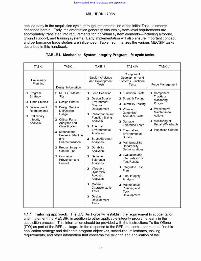
applied early in the acquisition cycle, through implementation of the initial Task I elementsdescribed herein. Early implementation generally ensures system-level requirements areappropriately translated into requirements for individual system elements—including airborne,ground support, and training systems. Early implementation will also ensure important conceptand performance trade studies are influenced. Table I summarizes the various MECSIP tasksdescribed in this handbook.
TABLE I. Mechanical System Integrity Program life-cycle tasks.
TASK I TASK II TASK III TASK IV TASK V
PreliminaryPlanning
Design Information
Design Analysesand Development
Tests
ComponentDevelopment and
Systems FunctionalTests
Force Management
ProgramStrategy
Trade Studies
Development ofRequirements
PreliminaryIntegrityAnalysis
MECSIP MasterPlan
Design Criteria
Design ServiceLife/DesignUsage
Critical PartsAnalyses andClassification
Material andProcess SelectionandCharacterization
Product IntegrityControl Plan
CorrosionPrevention andControl
Load Definition
Design Stress/EnvironmentSpectraDevelopment
Performance andFunction SizingAnalysis
Thermal/EnvironmentalAnalyses
Stress/StrengthAnalyses
DurabilityAnalyses
DamageToleranceAnalyses
Vibration/Dynamics/AcousticAnalyses
MaterialCharacterizationTests
DesignDevelopmentTests
Functional Tests
Strength Testing
Durability Testing
Vibration/Dynamics/Acoustics Tests
DamageTolerance Tests
Thermal andEnvironmentalSurvey
Maintainability/ReparabilityDemonstrations
Evaluation andInterpretation ofTest Results
Integrated TestPlan
Final IntegrityAnalysis
MaintenancePlanning andTaskDevelopment
ComponentTracking/MonitoringProgram
PreventativeMaintenanceActions
Monitoring ofRepairs/Overhauls
Inspection Criteria
4.1.1 Tailoring approach. The U.S. Air Force will establish the requirement to scope, tailor,and implement the MECSIP, in addition to other applicable integrity programs, early in theacquisition process. This information should be provided with the Instructions To the Offeror(ITO) as part of the RFP package. In the response to the RFP, the contractor must define hisapplication strategy and delineate program objectives, schedules, milestones, taskingrequirements, and other information that concerns the tailoring and application of the
Downloaded from http://www.everyspec.com
MIL-HDBK-1798A
7
requirements of this handbook. Tailoring and application will be one of the MECSIP Task Ielements, as described in 4.2. The purpose for developing a program strategy and tailoringapproach is to ensure appropriate program management and planning attention is given to theimplementation of the MECSIP. Especially important is the need to ensure system technicalrequirements and design criteria reflect overall operational needs, and that proper integration,plans, tasking, and scheduling are provided throughout the acquisition.
4.1.2 Implementing Statement of Work. The MECSIP procurement is normallyaccomplished through Statement of Work tasks. In accordance with procurement guidelines, aStatement of Work must be developed that covers the tailored tasks, subtasks, strategy, plans,and the effort to be accomplished.
4.2 (Task I) Preliminary planning. Task I is intended to be accomplished either in advanceof, or at the beginning of the System Development and Demonstration phase (formerly knownas the Engineering and Manufacturing Development phase). The purpose of Task I is to scopethe tailoring, planning, and development strategy for applying the MECSIP. The tasks expectedduring this period for major weapon system procurements include the methods detailed in thesubparagraphs which follow.
4.2.1 Program strategy. A MECSIP program strategy must be developed to establishdefinitive objectives early in the acquisition. The MECSIP strategy will support and be one ofthe elements of the overall acquisition strategy for the system. Areas such as materials,processes, manufacturing, testing, facilities, manpower, funds, and schedules are all involved indeveloping this strategy. Technology improvements and advancements necessary to achievespecific program objectives must be defined, quantified, scheduled, and evaluated for costbenefits. The strategy will become progressively definitive as the acquisition strategy matures,and as it becomes possible to develop and weigh alternative approaches to satisfy systemneeds. Simply stated, the strategy should address the "what", "how", "when", and "with what"aspects of applying the MECSIP to full acquisition and deployment of the systems andequipment.
4.2.2 Trade studies. As part of the early acquisition process, system engineering tradestudies should be conducted at both the system- and component-level, as appropriate. Thepurpose of these trade studies is to examine alternative approaches which satisfy the systemoperational safety, suitability, and effectiveness. Proper consideration must be given tosupportability, reliability, maintainability, and cost, in addition to technical performance, whenthese trade studies are performed. The use of new computer programs and technologies forcomponent tracking and monitoring should be included in the trade studies.
4.2.3 Development of requirements. Part of the early acquisition process should be devotedto the study and refinement of system-level requirements as they evolve from the considerationof operational needs, supportability goals, etc. As part of this refinement process, systemrequirements should be evaluated, particularly in conjunction with the early trade studies. Theobjective is to enter into system development with optimized and balanced design requirements.
4.2.4 Preliminary integrity analysis. The pre-development activity should define the risks ofthe candidate system concepts to achieve performance and integrity goals. This requires anunderstanding of the physical concepts and failure modes, and requires a limited database thatdefines the candidate materials, processes, and technologies. These analyses may be
Downloaded from http://www.everyspec.com
MIL-HDBK-1798A
8
particularly important, since they typically support the early engineering trade studies.Preliminary analyses should include, but not be limited to, equipment sizing, estimates ofcomponent and system service life potential, failure modes analysis, classification of criticalcomponents, and identification of hidden failures.
4.3 (Task II) Design information. This task encompasses the efforts required to apply theexisting technical database and operational criteria to the initial design, development, materials,processes, and production planning for each specific system or equipment application. Theobjective is to ensure the operational and support needs are met. Tasking is initiated as earlyas practical in the procurement. Several subtasks are iterated during the design developmentcycle and finalized later in the system development. Information in Task II is developed by thecontractor based on instructions provided by the procuring activity in the ITO and supported bythe results of Task I.
4.3.1 MECSIP master plan. A master plan will be developed to define and document thedetails for accomplishing all tasks and subtasks of the MECSIP. The plan will define overallstrategy and the time-phased scheduling of the various integrity tasks for design, development,qualification, and force management of the specific system hardware. The plan will includediscussions of unique features of the program, exceptions to this handbook, a completediscussion of each proposed task, rationale for each task and subtask, and an approach toaddress and resolve all problems anticipated in the execution of the plan. The development ofthe schedule must consider other program interfaces, impact of schedule delays (e.g., delaydue to test failures), mechanisms for recovery, programming, and other potential problemsareas.
The plan will include the time-phased scheduling and integration of system development taskswhich support performance and integrity requirements for the equipment being acquired. Theplan is intended to highlight programmatic issues, schedules, analyses, functional tests,development and verification tests, test data, evaluation criteria, contractor/vendor tasks,milestones, etc. The plan must identify approaches for the analyses and tests, includingdescriptions of proposed analytical and test methods, assumptions, data criteria, etc. The planmust include the design criteria to be used, the basis for criteria selection, and the relationshipof criteria to overall system requirements.
The MECSIP master plan is a living document, updated periodically throughout the life of thesystem. The master plan must be developed by the contractor during system development andsubmitted in accordance with specific program requirements. While the specific content of theplan will not be contractual, the document will be subject to U.S. Air Force approval. It mustorganize the approach to include all elements of each specific system application. It mustaddress contractor, subcontractor, and vendor equipment, as well as government-furnishedequipment (GFE) and off-the-shelf (OTS) equipment. It will be the responsibility of the contractorto address GFE and OTS equipment through an assessment approach consistent with thishandbook. The approach must ensure that system requirements are satisfied and thatmaintenance requirements can be defined and included in the overall force management plan.
It is the responsibility of the System Program Office to establish and maintain the master planduring the sustainment phase of the program. The plan should include the actions contained inTask V and should capture the knowledge and experience gained during the previous phases.
Downloaded from http://www.everyspec.com

MIL-HDBK-1798A
9
4.3.2 Design criteria. The contractor must translate the system requirements into specificdesign criteria to be used for material selection, equipment sizing, design, analysis, and test.The objective is to ensure criteria which reflect the planned usage of the systems are applied tothe development and verification process so that specific performance, operational, andmaintenance/support requirements can be met. The task of developing design criteria beginsas early as practical in the development cycle. Specific criteria must be developed to supportfunctional performance, durability, damage tolerance, strength, vibration/dynamic response,maintenance, integrity management, and other specified requirements.
4.3.3 Design service life/design usage. Design criteria will be derived to reflect requiredcomponent/system service life and usage as contained in the individual system-levelrequirement documents. These criteria may reflect findings of system trade studies conductedearly in the acquisition process (i.e., Task I). The operational service life requirements may besatisfied by a designed-in, maintenance-free operating period and scheduled preventativemaintenance. In early trade studies, the contractor must evaluate the impact of maintenance-free versus scheduled maintenance operating periods on cost, weight, and performance. Thestudies must also consider the logistics and support requirements, the overall maintenanceconcept, and the implementation approach for component/system maintenance tracking. Thetracking system must assist the MECSIP manager in performing the duties listed in Task V.The result of these trade studies will be used to define the design service life criteria for specificcomponents as well as in-service maintenance required to achieve the specified total requiredoperational service life. Establishment of designed-in scheduled preventative maintenance mustbe consistent with the operational, logistics, and support requirements. The approach todefinition and development of the design service life and design usage will be included in theMECSIP master plan.
4.3.4 Critical parts analysis and classification. As early as practical, the contractor mustestablish an approach to identify and classify critical hardware components for the specificsystem. Critical parts must be identified for application of specific criteria (e.g., durability anddamage tolerance) related to materials, processing, manufacturing, maintenance tracking, etc.As a minimum, the following five categories (defined in section 3) will be used:
a. Safety-critical componentsb. Mission-critical componentsc. Durability-critical componentsd. Durability-noncritical componentse. Other/expendable components.
This classification must consider the failure modes, effects, and criticality analysis for eachspecific system. Criteria and evaluation procedures should be developed which consideroverall safety, mission criticality, maintenance, supportability, cost, etc. The overall approach,analysis assumptions, and candidate component lists are documented in the MECSIP masterplan.
Downloaded from http://www.everyspec.com
MIL-HDBK-1798A
10
4.3.5 Material and process selection and characterization. The contractor will identify andprovide rationale for the materials and manufacturing processes to be used for each componentof the system. Materials selection must be accompanied by an adequate database andsupporting specifications to support design methodologies. Industry process specificationsshould be used wherever possible to offer maximum benefit to the users to replace parts inaged systems and to establish second sources. The contractor will document the completerationale, trade studies, and evaluation criteria used in the final selection. The rationale willconsider prior operational experiences and technical data.
A plan will be developed which describes the processes and procedures to be used tocharacterize and select materials and processes for all elements of the system. The planshould contain equipment requirements, available database(s) for proposed materials,additional test requirements, and the rationale to be used for final material and processselections. The plan should identify methods and criteria for vendor substantiation, testrequirements for material and process characterization, etc. The contractor will develop anapproach to ensure minimum properties and processes as required to support the productintegrity control plan (see 4.3.6). The material and process selection and characterization planwill be included as part of the MECSIP master plan.
4.3.6 Product integrity control plan. The contractor must implement special controls toensure the required integrity characteristics of critical parts throughout production andsustainment is achieved. Candidates for specialized controls are parts classified as safety-,mission-, and durability-critical, and items which have hidden failure modes. Specializedcontrols may be required for materials, processes, manufacturing, quality, nondestructiveinspection, corrosion prevention, etc. As a minimum, this approach and plan will include:
a. the critical parts list and selection rationale (see 4.3.4);b. basic material properties, allowables, and process data used in the analyses and tradestudies;c. procedures to identify critical parts and special provisions on the component drawings;d. nondestructive inspections to be performed on safety- and mission-critical componentsto support damage tolerance requirements;e. special nondestructive inspection capability demonstration programs to be conducted insupport of damage tolerance requirements (manufacturing and in-service capability);f. acceptance/proof tests for individual components, as required;g. material procurement specifications and process specifications to ensure critical partshave the required properties (e.g.; strength, fracture toughness, fatigue);h. requirements for material/part traceability for safety- and mission-critical componentswhich require special processing and fabrication operations; andi. all vendor and supplier controls for these items.
Economic trade studies will be conducted to ensure the effective development andimplementation of this plan. The product integrity control plan would be one of the primary dataitems submitted under the MECSIP and would be subject to U.S. Air Force approval.
Downloaded from http://www.everyspec.com
MIL-HDBK-1798A
11
4.3.7 Corrosion prevention and control. The contractor will define his approach to thedevelopment, evaluation, and incorporation of corrosion-resistant materials, protectivetreatments, finishes, etc. The selection of materials, finishes, and protection schemes mustconsider the service-life requirements, environmental impacts, and sustainment costs. Effectsof corrosion on the mechanical properties of the materials must be established, as well as thesuitability of dissimilar materials not to induce damage (galvanic effects). The plan toaccomplish these tasks will be incorporated in the MECSIP master plan. Implementation of thisplan will be in accordance with the product integrity control plan. (See 4.3.6.)
4.4 (Task III) Design analyses and development tests. Analyses and development tests willbe performed to support the design activity and to verify that the specific performance, function,and integrity requirements have been met. These tasks should be conducted using methodswhich have been verified on prior programs or which will be verified during system/componentdevelopment. All analytical approaches and development test plans will be described in theMECSIP master plan.
4.4.1 Design analyses. Design analyses include, but are not limited to, the elements detailedin the subparagraphs which follow.
4.4.1.1 Load definition. This analysis is used to define the magnitude and distribution ofsignificant static, dynamic, and repeated loads which the equipment encounters when operatedwithin the envelope established by the specific system requirements and detailed designcriteria. This analysis involves identifying the internal and external operating load sources aswell as inertial effects imposed by accelerations, decelerations, angular velocities, external airloads, and gyroscopic moments. Where applicable, the loads will include the effects oftemperature and system installation (e.g., dynamic response and deformation of the airframe orsupport structure). Repeated load sources imposed by the airframe will be included, asapplicable. The analysis must address flight and ground operation as well as maintenance,storage, and transportation.
4.4.1.2 Design stress/environment spectra development. This analysis will be used todevelop the design stress/environment spectra for individual system elements. The designstress/environment spectra must characterize the repeated operating loads, pressures, thermalcycles, and chemicals in a format which accounts for the primary functional duty cycle andusage of the equipment. The intent is to develop a spectrum that characterizes the significantusage events which may affect primary failure modes (e.g.; fatigue, cracking, stress, corrosion,cracking, wear, etc.). This spectra will be used to assist in material selection, component sizing,and performance/life verification.
4.4.1.3 Performance and function sizing analyses. Analyses will be conducted to supportsizing, configuration development, and to verify specific performance requirements.
4.4.1.4 Thermal/environmental analyses. These analyses will be conducted to determinethe steady-state and transient thermal and chemical environments for individual elements of thesystem. Thermal and chemical environments will be used in the design, analyses, and testing(e.g.; strength, durability, damage tolerance, vibration/dynamics, etc.) of the individualcomponents and/or systems.
Downloaded from http://www.everyspec.com
MIL-HDBK-1798A
12
4.4.1.5 Stress/strength analyses. These analyses will be conducted to determine thestresses, deformations, and margins of safety which result from the applications of designconditions, loads, and environments. These analyses are required for verification of strength.
4.4.1.6 Durability analyses. These analyses will be conducted to verify individual systemcomponents will meet the service life requirements when subjected to the operational usageand environments. Analyses will be conducted early in the acquisition phase to support designconcept development, material selection, and weight/cost/performance trade studies. Earlyanalyses will enable identification of failure modes and sensitive areas, particularly those withpotential for early fatigue, wear, environmental degradation, or thermal distress. Allowable limitsfor critical failure modes, cracking, wear, and environmental degradation must be defined aspart of these analyses. Early analysis should be emphasized to minimize occurrences ofdeficiencies during subsequent development and functional testing. Material and process datarequired to support analytical methods will be generated in accordance with 4.4.2.1.
Durability analyses will be used to predict the operational life with and without scheduledmaintenance. The analyses must consider material variability, initial manufacturing quality, andfunctional limits for each critical failure mode. Analyses must show that adverse cracking, wear,delamination, or other damage formation will not occur within the required operational serviceperiod when subjected to the required usage and environments. Components should bedesigned and analyzed to twice the required service life using nominal properties, tolerances,etc., to account for variations in material properties, processes, manufacturing, etc. Individualcomponent analytical results will be used to prove the available economic life of the total systemis at least equal to the required operational service life specified in the contractual documents.
4.4.1.7 Damage tolerance analyses. Damage tolerance analyses must be conducted early inthe acquisition phase to support design concept development, material selection, andweight/cost/ performance trade studies. Early analyses will enable identification and cost-effective correction of structurally-sensitive areas which do not meet specific flaw or cracktolerance, redundancy, leak before break, or other damage tolerance characteristics. Materialproperty data required to support analysis will be developed in accordance with 4.4.2.1.Analytical methods must be verified with test data. Damage tolerance analyses must predictflaw tolerance margin, fail-safe operational life (including leak before break) and other featuresincorporated to satisfy damage tolerance criteria. Components should be designed andanalyzed to twice the required service life using nominal properties, tolerances, etc., to accountfor variations in material properties, processes, manufacturing, etc. The damage toleranceanalyses apply to safety-critical and mission-critical components only.
4.4.1.8 Vibration/dynamics/acoustic analyses. Dynamics analyses must be conducted toestablish component vibration and acoustic mode shapes and frequencies. An analyticaldynamic model of the system and/or critical components must be developed to identify criticalsystem modes, potential forcing functions, and resonance conditions.
Downloaded from http://www.everyspec.com
MIL-HDBK-1798A
13
4.4.2 Development tests. The amount and type of tests required to support the design anddevelopment will vary. These will include, but not be limited to, the tests described in thefollowing subparagraphs.
4.4.2.1 Material characterization tests. Material characterization data such as strength,fatigue, fracture toughness, crack growth rate, corrosion resistance, wear, and thermal stabilityare required to support the design and to meet specific integrity-related requirements. Whenthe data is not available, material properties must be established by test. Test specimens mustbe fabricated to include critical manufacturing processes (e.g.; forming, joining, assemblytechniques). The test plan will identify the vendor material characterization test requirementsnecessary to ensure minimum required properties in finished parts throughout production.
Materials property data must be statistically significant. All materials must be procured toexisting materials and process specifications. Any changes to the materials and processspecifications may require retest. Section thickness, thermal treatments, and manufacturingmethods must be the same as the production hardware.
Existing data obtained from literature sources or previous program experiences may be used.However, for critical component application (see 4.3.4), these properties must be verified usingspecimens fabricated from actual parts, as required.
Materials for critical systems and components (see 4.3.4) should be characterized to include thefull range of design and operating conditions. Cyclic loading and time-dependent propertiesshould reflect the environmental and design usage defined in the contractual documents or asmodified in this handbook.
4.4.2.2 Design development tests. Development tests must be conducted to supportcomponent and system sizing, material selection, durability assessment, design concept trades,and analysis verification, and to obtain an early indication of compliance with specificperformance requirements. Examples of design development tests are tests of coupons, smallelements, joints, fittings and sealing concepts, controls, linkages, operating mechanisms, andmajor components—such as pumps, reservoirs, and actuators.
The scope of development tests will be established in the MECSIP master plan and will includerationale for the tests, description of the test articles, test duration, and criteria for interpretationof test results.
4.5 (Task IV) Component development and systems functional tests. These tests areintended to verify the system integrity performance. Tests may be conducted on systems orindividual components, in simulated system installation environments, or during flight andground testing. All testing will be planned, scheduled, and conducted in accordance with theoverall system test plan and specific requirements. Tests will include, but not be limited to,those described in the following subparagraphs.
4.5.1 Functional tests. Full-scale component, system ground (e.g.; iron bird, simulator),and/or flight tests will be required to verify specific functional performance requirements.Examples of functional testing include fluid flow performance, leakage, brake performance, andflight control performance. When practical, these tests should be used to evaluate and verifyequipment integrity.
Downloaded from http://www.everyspec.com
MIL-HDBK-1798A
14
4.5.2 Strength testing. Testing of components, assemblies, and/or systems must beperformed to verify strength requirements. Thermal and other environmental effects must besimulated along with load applications when these conditions impose significant effects on thecomponent strength. Test results will be used to evaluate design margins and growthcapability.
4.5.3 Durability testing. A test program will be conducted to substantiate the overall durabilityof system components. Durability testing consists of component, assembly, and/or full systemtests which simulate repeated loads and environmental conditions that represent design usageand design service life criteria.
Tests, particularly for expensive and long lead development items, should be scheduled early toallow for identification and correction of critical areas and failure modes (e.g.; cracking,deterioration, leakage). All durability verification testing should be successfully completed priorto delivery of the first production system. Testing milestones will be established as part of theoverall system test planning.
The results of durability testing will be the basis for any design modifications, specialinspections, and maintenance actions for critical components and installed systems.
Test duration requirements will vary depending on the specific application. Components shouldbe required to demonstrate two design service lives to impart confidence that the componentwill achieve one lifetime in service. Test articles must be selected which represent theproduction configurations. Test loadings and environments must represent the significantelements of the design service usage spectrum. Truncation and simplification of the repeatedloads and environments must be substantiated by analysis and/or test to verify equivalency tothe design usage spectrum.
All test results will be evaluated and compared against the original predictions for wear and life.When damage is worse than predicted, the affected parts will be analyzed and appropriatecorrective actions taken.
Safety- and mission-critical parts are replaced during service at one-half the demonstrated life.
4.5.4 Vibration/dynamics/acoustics tests. These tests are conducted to verify the vibration,dynamics, and acoustics response characteristics of the installed system and/or critical systemcomponents.
4.5.5 Damage tolerance tests. These tests are conducted to verify the damage tolerancecharacteristics of safety-critical and mission-critical components. These tests are used toestablish damage tolerance margins, crack growth rates, critical crack lengths, residualstrength, fail safety, leak before break, or other characteristics defined by the specific damagetolerance criteria. No testing will be necessary for relatively simple geometries and well-characterized materials, if there is adequate confidence in the accuracy of the analysis.Coupon, element, or component-level testing will be necessary for all other cases. Thecombination of analysis and test should demonstrate two design service lives to impartconfidence that the component will achieve one lifetime of service. An in-service inspectionperiod will be established at one-half the validated design service life. Components whichsatisfy damage tolerance through high durability margins must be tested to the appropriate
Downloaded from http://www.everyspec.com
MIL-HDBK-1798A
15
number of equivalent lives (typically four or more) necessary to gain high confidence that thecomponent will achieve one lifetime of service.
4.5.6 Thermal and environment survey. Temperatures, loads, and other environmentalfactors must be measured during the component development and system functional and flighttests. These values must be compared against predicted values to verify design criteria. Dataobtained from these surveys will be used to adjust operational limits and maintenance actionsas determined from analysis and tests. The information will also be retained as "lessonslearned" to assist in the development of criteria for future applications. The plan and approachfor conducting this survey will be included with the MECSIP master plan.
4.5.7 Maintainability/reparability demonstrations. The contractor will conduct a program todevelop and demonstrate maintenance procedures. The demonstrations may be conducted inconjunction with development and/or full system tests. Authorized repairs and repair limits mustbe in accordance with the documented maintenance and logistics requirements. Testing will beconducted as required to validate the integrity of authorized repairs.
4.5.8 Evaluation and interpretation of test results. The contractor will describe theprocedures to evaluate, interpret, and incorporate all test findings (e.g.; cause, correctiveactions, program implications, maintenance projections, and costs). This evaluation will definecorrective actions required to demonstrate design requirements are met. Each problem(cracking, yielding, wear, leakage, etc.) that occurs during testing must be evaluated.Inspections, disassembly, and destructive tear-down evaluations will be conducted.
4.5.9 Integrated test plan. All test requirements identified for the specific system equipmentmust be defined, scoped, and scheduled in an integrated test package. This includes testsassociated with development and full qualification, as well as any subsequently-scheduledgrowth or margin testing. Vendor and supplier tests will be included in this plan. The contractorwill seek the most economical balance of requirements, verification, and test articles whenintegrated tests are compiled. The integrated test plan will be incorporated into the overallsystem test plan.
4.5.10 Final integrity analysis. The design analyses (Task III) for safety-, mission-, anddurability-critical components must be updated to account for significant differences betweenanalyses, tests, and the thermal/environmental/load survey. These updated analyses willprovide data on operational limits to be used in maintenance, inspection, and repair times forcritical components. These analyses and evaluation of test results will be utilized to developmaintenance and inspection planning. Analyses to be updated will include, but not be limited to,the following:
a. durability;b. strength;c. damage tolerance;d. loads; ande. stress—environmental and thermal.
These final analyses will be developed following completion of the design/development test andanalysis phase and will be submitted in accordance with specific program requirements. Thisplan will require U.S. Air Force approval.
Downloaded from http://www.everyspec.com
MIL-HDBK-1798A
16
4.5.11 Maintenance planning and task development. Required maintenance actions (e.g.;inspection, repair, or replacement) will be developed to ensure the integrity and operability ofthe system for the required operational service life. Initial maintenance action requirements andtimes will be based on updated analyses and test data in accordance with 4.5.10. These actionsand times will be modified, as appropriate, according to information and experience from in-service operation.
The required maintenance action times must be based on duty cycles and usage in accordancewith the specific design criteria and system requirements. The initial maintenance plan will bedeveloped following completion of the design/development test and analysis phase and will besubmitted in accordance with specific program requirements. This plan will requireU.S. Air Force approval.
4.6 (Task V) Force management. Force management includes those actions necessary toensure that the safety, reliability, and durability requirements established in Tasks I through IVare met and maintained throughout the entire life of the weapon system. The MECSIP managerhas overall responsibility to manage the health of the systems, regardless of the overhaulingdepot. He will be part of any management process that impacts the safety, suitability,effectiveness, reliability, and durability of a system or its components. The MECSIP managerwill: 1) update and maintain the MECSIP master plan as necessary to reflect the needsassociated with sustainment, 2) establish and monitor a component tracking program,3) establish preventative maintenance actions, 4) establish repair/overhaul procedures, and5) establish inspection criteria.
4.6.1 Component tracking/monitoring program. In-service failure data must be constantlymonitored. Three years of data must typically be collected before premature failures can beeffectively identified. After three years, the MECSIP manager’s tracking program shouldautomatically notify him if the Mean-Time-Between-Failure (MTBF) rate changes more thantwenty-percent over an 18-month time period. The MECSIP manager should review thesituation and determine if further engineering analysis is required. If an analysis is required andit exceeds the facilities or skills of the assigned personnel, contractual assistance may be used.The MECSIP manager will fund all requests for analysis generated by his office. The intent ofthe analysis is to increase the Component Time to Failure (CTTF) (the point at which acomponent experiences an inherent failure that requires its removal from the air vehicle) to anacceptable level. The tracking program should provide a monthly failure listing for each systemto alert the MECSIP manager of potential failures. The MECSIP manager will establish a priorityschedule for each system based on 4.3.4 (critical parts analysis and classification) and oncurrent data. The MECSIP manager should rely on the Material Deficiency Report/QualityDeficiency Report system for alerts prior to the three years of collected data.
4.6.1.1 Operational usage data. Weapon systems must have adequate instrumentation tomonitor air vehicle usage, thus permitting continual updates to the CTTF predictions. Theinstrumentation should monitor parameters such as landing gear and weapon bay door cycles,flight control actuation, electrical power distribution, and temperature differentials. The trackingprogram must be able to accept and utilize this data.
4.6.2 Preventative maintenance actions. Preventative maintenance is designed to precludecomponent failure. Based upon the maintenance-free operating period established inTasks III–IV, as well as available field data, a time-change or other preventative maintenanceaction can be planned during scheduled downtimes to prevent loss of scheduled missions and
Downloaded from http://www.everyspec.com
MIL-HDBK-1798A
17
to ensure a high level of safety. A unit’s mission profile may have a significant effect on theCTTF. For example, bases which perform pilot training will generally have an increase inlanding gear and flight control malfunctions, thereby reducing their CTTF. The trade studiesperformed in Tasks I through III will help the MECSIP manager select a tracking program thatwill best establish the CTTF.
4.6.2.1 Flight-hour time change. A flight-hour time change should be considered forproblematic components which are durability critical or have a hidden failure mode, and have anestablished, reliable CTTF. Components should be replaced at or prior to the CTTF inconjunction with regularly-scheduled maintenance (Home Station Checks, Major IsochronalInspections, Phase or Periodic Depot Maintenance). Prime candidates for time change aremechanical assemblies such as actuators, jackscrews, valves, pumps, tension regulators, andlanding gear. Benefits derived from the time changes are numerous. However, most electroniccomponents typically do not benefit from the time-change actions. Safety- and mission-criticalcomponents have their own unique set of requirements, which are defined in 4.6.4.1.
4.6.2.2 Calendar time change. Calendar time change components are durability non-criticalcomponents whose failure would have a minor impact on the system but would still requiremaintenance for continued flight operations. These components, when identified, can berepaired or replaced during scheduled maintenance such as Isochronal Inspections, and Phaseor Periodic Depot Maintenance. Similar to time change, these components are repaired orreplaced on a calendar-inspection basis, not a flight-hour basis.
4.6.2.3 On-equipment repairs. It may be more advantageous during the operational servicelife of a component to make minor repairs or replace an attaching Line Replacement Unit (LRU)than to replace the component. Repairs may include replacement of the rubber seals, rod ends,bearings, etc. These repairs should be identified in Task IV, and technical data relative to therepairs should be made available for reference.
4.6.2.4 Lubrication/cleaning and adjustments. The system may require periodicmaintenance if it is to perform correctly. For example, the MECSIP manager must ensure thatproper wash and lube are scheduled to prevent corrosion, and that any necessary adjustments(e.g., to flight controls or landing gear) are made during the scheduled maintenance. Wartimeconditions do not preclude performance of these scheduled maintenance tasks.
4.6.2.5 Overhaul of systems. As systems age, wear in individual components may lead tounreliable and eventually failed systems. The tendency is to replace the link in the system thathas the most wear and to return the air vehicle to service. This provides an inexpensive andrapid fix; however, this type of “piece-meal” repair lasts only until the next link fails. Once a unitor system reaches this condition, the refurbishment of the entire unit or system to “like-new”condition becomes more economical than the continued removal of an air vehicle from serviceto accomplish what are essentially temporary repairs. While entire system replacement mayseem expensive, the cost must be compared to the time lost for air vehicle downtime. Itemssuch as torque tubes, rod end bearings, quadrants, and pulleys are prime candidates for thistype of maintenance. These items require little attention from the MECSIP manager in thebeginning but must be part of the matrix as the air vehicle ages.
As systems are initially received for overhaul (first scheduled depot maintenance), one or morelead-the-fleet (high time) units should be selected for a complete disassembly and inspection.The purpose is to compare the degradation against that predicted. If degradation is found in
Downloaded from http://www.everyspec.com
MIL-HDBK-1798A
18
areas not expected, or the degradation is more severe than predicted, appropriate actions mustbe taken to prevent in-service failure and/or unscheduled maintenance.
4.6.2.6 Replacement of original equipment. Many components are designed with a servicelife that exceeds that of the air vehicle. As a result, little or no preventative maintenance isrequired. Examples include actuating cylinders, electrical connectors, and bleed ducts. Wear-out mechanisms for other components become well defined as the system ages. Identificationand correction of these components are becoming increasingly important as more aircraftcontinue to remain in service past their original design lives. In some cases, upgrades to thesame equipment can easily be provided with advanced materials which will increase thecomponent’s life.
4.6.2.7 Replacement of obsolete equipment. Some older aircraft may use antiquatedequipment. Newer technology may enable replacement with improved reliability. An exampleof this would be the new fly-by-wire versus the mechanical linkage for flight controls. It may becheaper and more feasible to replace these systems with the newer technology. The MECSIPmanager must be ready to make this type of decision based on collected data and tradestudies.
4.6.2.8 Environmental regulations. Environmental regulations must be considered in theselection of materials. Changes in the environmental laws may also drive replacementprograms. Any replacement material must be analyzed and/or tested to ensure it meets theoriginal design and service life requirements. For uncharacterized materials, characterizationtesting must be conducted in accordance with 4.4.2.1. Asbestos seals and clamps areexamples of items which must be replaced. Depleted uranium flight control counter-weightsmust be refurbished to prevent hazardous materials contamination. Paint, plating, cleaning, andcorrosion control systems must be updated. The MECSIP manager must receive periodicbriefings on environmental changes to ensure safe maintenance and operational procedures.
4.6.3 Monitoring of repairs/overhauls. If a component fails, it can be either thrown away orreturned for overhaul, based upon the results of a life cycle cost analysis. To “overhaul” acomponent is to return it to a “like-new” condition. To “repair” a component is simply to make itserviceable. The MECSIP manager must ensure serviceable items returned to base supplyhave been “overhauled” or meet the intent of “overhaul.” Unfortunately, it is difficult orimpossible to restore a used part to a “like-new” condition. Parts which were not replacedduring overhaul have some percentage of their original life consumed. Plating landing gear tobuild-up areas where corrosion was removed can affect the overall properties of the unit. It isthe MECSIP engineer’s responsibility to ensure that any degradation in overall condition isacknowledged and accounted for in the overhaul process.
Downloaded from http://www.everyspec.com
MIL-HDBK-1798A
19
4.6.3.1 Field/base-level maintenance. The MECSIP manager must either ensure that eachbase has the proper “overhaul” capabilities (i.e.; test equipment, technical orders, platingequipment, etc.) for a specific component or restrict that base from performing the overhaul.This can be best accomplished by ensuring the Aircraft Scheduled Inspection and MaintenanceRequirement technical orders are current and enforced. If a component is repaired at the baselevel, then consideration should be given to a requirement that the component be periodicallyreturned to the depot (e.g., after the third base-level overhaul) to ensure the reliability of thecomponent continues to be met. The MECSIP manager can recommend no base-level repairsand establish regional repair facilities. The cost of training technicians and test equipment mayprohibit base-level repairs and may lead to regional or “Queen Bee” facilities. The MECSIPmanager must have a list of contacts for each base and be aware of their capabilities. If anoverhaul is performed, the master maintenance action log originated by the owning depot mustbe updated.
4.6.3.2 Depot-level maintenance. The depot strongly influences the continued reliability ofthe components and systems. One-of-a-kind test equipment, special tools, and chemical platingare combined with special training to ensure components are returned to a “like-new” condition.Each component that enters the depot should have a Master Maintenance Action Log attachedto the component or recorded against its serial number in a computer database. Allmaintenance actions which occur on the component should be annotated in the log to assist inmaintaining the reliability of the component. This log must be kept for the life of the component.Components which enter the depot will be overhauled and have the parts replaced, as indicatedby the maintainability/reparability demonstrations contained in 4.5.7. If a part shortage occursand a part listed for replacement during overhaul is not available, Air Logistics Center (ALC)-engineering may authorize the re-use of certain parts for one overhaul only. The maintenancelog will be annotated to reflect this, and the part must be replaced during the next overhaul. Ifthe reliability rate drops after numerous overhauls, the MECSIP manager may elect to restrictthe number of overhauls a component may undergo. The MECSIP manager, in concert withALC engineering, is responsible for ensuring component reliability.
4.6.4 Inspection criteria. The inspection criteria are established during Tasks III and IV. Thelist is constantly updated using data collected from operational units, personal contacts, base ordepot inspections, and maintenance deficiency reports. The inspection requirements shouldestablish the equipment to be inspected, its inspection schedule, and its inspection criteria. Theinspection process is a key to ensuring the MECSIP process is effective. Computer programsmust link all bases which perform inspections, compile and list common deficiencies, andidentify potential problem areas. Systems are generally modified based on inspection reportsand maintenance man-hours annotated in the reports. The MECSIP manager will meet yearlywith all major inspection chiefs to discuss improvements and new inspection criteria. TheMECSIP manager will establish an electronic bulletin board to assist in the daily communicationwith maintenance personnel and will establish a list of contacts for each base.
4.6.4.1 Damage-tolerance-critical components. Safety- and mission-critical componentsare categorized as damage-tolerance critical since failures cannot be tolerated. Thecomponents must be inspected and/or replaced at some portion of their demonstrated servicelife to ensure failure-free operation. This is to account for flaws that may exist as the result ofthe material, manufacturing, and maintenance operations. The components are typicallyinspected at one-half the demonstrated life to assess the size of any existing flaws and todetermine their impact on remaining component life. Inspections will not be required over onelifetime of service if the components are designed and validated to the appropriate number of
Downloaded from http://www.everyspec.com
MIL-HDBK-1798A
20
multiple service lives (e.g., two lifetimes). The MECSIP manager must ascertain thedemonstrated life for each damage-tolerance-critical component and establish any necessaryinspection period. A replacement interval must be established for components which cannot beinspected.
5. NOTES
5.1 Intended use. Mechanical equipment and subsystems which provide power, control, andother contributory functions are essential elements of weapon systems. This handbook isintended to be used to establish programmatic tasks for the development, acquisition,modification, operation, and sustainment of the mechanical elements of airborne, support, andtraining systems.
5.2 Data requirements. When this handbook is used in an acquisition which incorporates aDD Form 1423, Contract Data Requirement List (CDRL), the data requirements identified belowmay be developed as specified by an approved Data Item Description (DD Form 1664) anddelivered in accordance with the approved CDRL. When the DoD Federal AcquisitionRegulation Supplement exempts the requirement for a DD Form 1423, the data specified belowmay be deliverable by the contractor in accordance with the contract or purchase orderrequirements. The deliverable data may include:
Paragraph Data Requirements Title
4.3.1 MECSIP master plan4.3.6 Product integrity control plan4.5.10 Final integrity analysis4.5.11 Maintenance planning and task development.
The current issue of the DoD 5010.12-L, Acquisition Management Systems and DataRequirements Control List (AMSDL), must be researched to ensure only current and approvedDIDs are cited on the DD Form 1423.
5.3 Subject term (key word) listing.
Equipment, Air Vehicle
Equipment, Ground Vehicle
Maintainability
MECSIP
Reliability
Systems, Mechanical
Downloaded from http://www.everyspec.com
MIL-HDBK-1798A
21/22
5.4 Responsible engineering office. The office responsible for development and technicalmaintenance of this handbook is ASC/ENFA, 2530 LOOP ROAD WEST, WRIGHT-PATTERSON AFB OH 45433-7101; DSN 785-9552, Commercial (937) 255-9552. Anyrequests for information that relates to government contracts must be obtained throughContracting Offices.
5.5 Changes from previous issue. Marginal notations are not used in this revision toidentify changes with respect to the previous issue due to the extent of the changes.
Custodians: Preparing activity:Army – AV Air Force – 11Air Force – 11
(Project SESS-0003)
Downloaded from http://www.everyspec.com
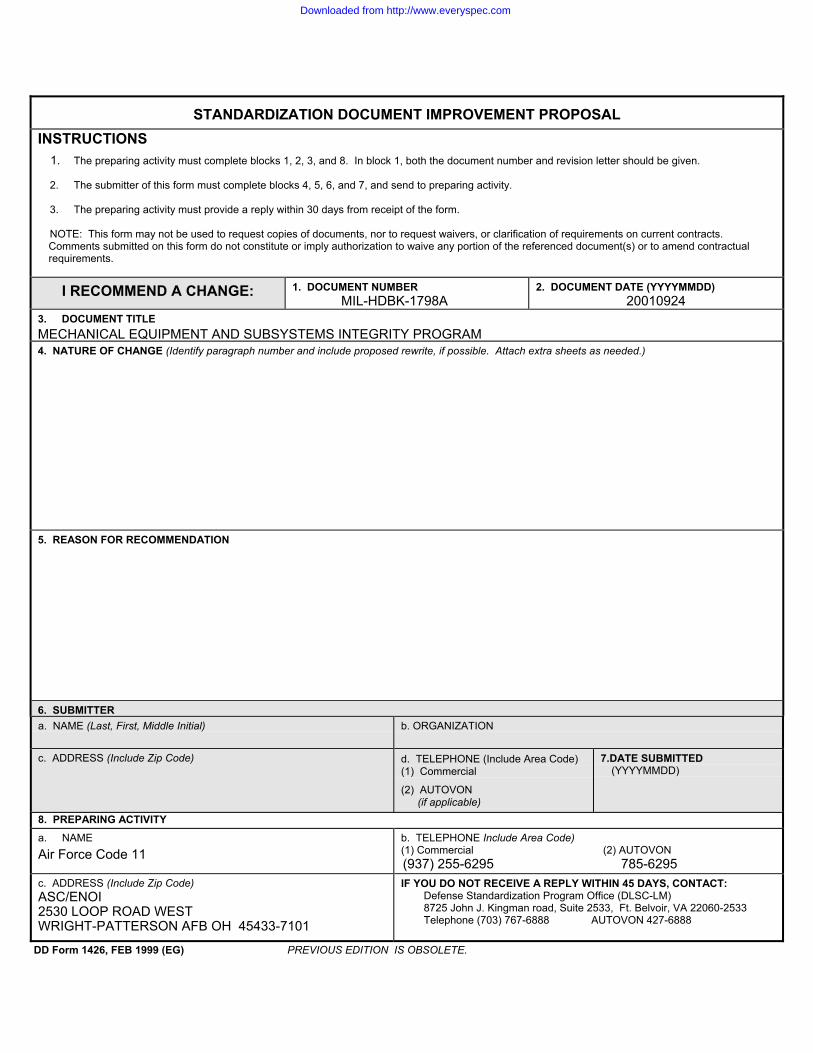
STANDARDIZATION DOCUMENT IMPROVEMENT PROPOSALINSTRUCTIONS
1. The preparing activity must complete blocks 1, 2, 3, and 8. In block 1, both the document number and revision letter should be given.
2. The submitter of this form must complete blocks 4, 5, 6, and 7, and send to preparing activity.
3. The preparing activity must provide a reply within 30 days from receipt of the form.
NOTE: This form may not be used to request copies of documents, nor to request waivers, or clarification of requirements on current contracts.Comments submitted on this form do not constitute or imply authorization to waive any portion of the referenced document(s) or to amend contractualrequirements.
I RECOMMEND A CHANGE: 1. DOCUMENT NUMBERMIL-HDBK-1798A
2. DOCUMENT DATE (YYYYMMDD)20010924
3. DOCUMENT TITLE MECHANICAL EQUIPMENT AND SUBSYSTEMS INTEGRITY PROGRAM4. NATURE OF CHANGE (Identify paragraph number and include proposed rewrite, if possible. Attach extra sheets as needed.)
5. REASON FOR RECOMMENDATION
6. SUBMITTERa. NAME (Last, First, Middle Initial) b. ORGANIZATION
c. ADDRESS (Include Zip Code) d. TELEPHONE (Include Area Code)(1) Commercial
(2) AUTOVON(if applicable)
7.DATE SUBMITTED(YYYYMMDD)
8. PREPARING ACTIVITYa. NAME Air Force Code 11
b. TELEPHONE Include Area Code)(1) Commercial (2) AUTOVON (937) 255-6295 785-6295
c. ADDRESS (Include Zip Code)ASC/ENOI2530 LOOP ROAD WESTWRIGHT-PATTERSON AFB OH 45433-7101
IF YOU DO NOT RECEIVE A REPLY WITHIN 45 DAYS, CONTACT:Defense Standardization Program Office (DLSC-LM)8725 John J. Kingman road, Suite 2533, Ft. Belvoir, VA 22060-2533Telephone (703) 767-6888 AUTOVON 427-6888
DD Form 1426, FEB 1999 (EG) PREVIOUS EDITION IS OBSOLETE.
Downloaded from http://www.everyspec.com