mechanical measurements and metrologynptel.ac.in/reviewed_pdfs/112106138/lec44.pdf · mechanical...
TRANSCRIPT
Mechanical Measurements and Metrology Prof. S. P. Venkateshan
Department of Mechanical Engineering Indian Institute of Technology, Madras
Module - 4 Lecture - 44
Measurement of Gas Composition and Smoke
This will be lecture 44 on our ongoing series on Mechanical Measurements. In the last lecture we mostly discussed about gas analysis. And to recapitulate; we had two types of gas analyzers, one in which the constituents are not separated, and they are measured in the form of mixture in which it exists. In the second case, we separated the constituents by a suitable technique, and then measured each one of them separately. So the separation was done by gas chromatograph. (Refer Slide Time: 1:16)
The other technique we talked about was, differential absorption which is specific to particular specie which absorbs at one wavelength and the neighboring wavelength does not absorb. The differential absorption is able to give us some idea about the concentration. The last one which I am going to describe here is the Orsat gas analyzer. In fact, it is one of the earliest gas analyzers which were used in power plants and so on. It is a very simple instrument, and again it separates the constituents by absorption in a reagent.
Subsequently, I am going to talk about smoke measurement which is also important, because the smoke or the particulate matter smoke in particular refers to the exhaust coming out from engines and so on but it could also mean particulates in general. So let us look at how to measure the particulates in the atmospheric air. The issues involved in that are collection and transmittance, and one of the instruments which we are going to discuss is the opacity meter. We will describe some ideas about how to collect and we will also discuss some details of iso-kinetic sampling. Flue gas analysis: flue gas means the gas is coming out of a boiler, and the gas will come out through the chimney, and we have to sample the gas at some suitable place and then subject it to analysis. One way of doing it is that is to use the Orsat analyzer. (Refer Slide Time: 3:14)
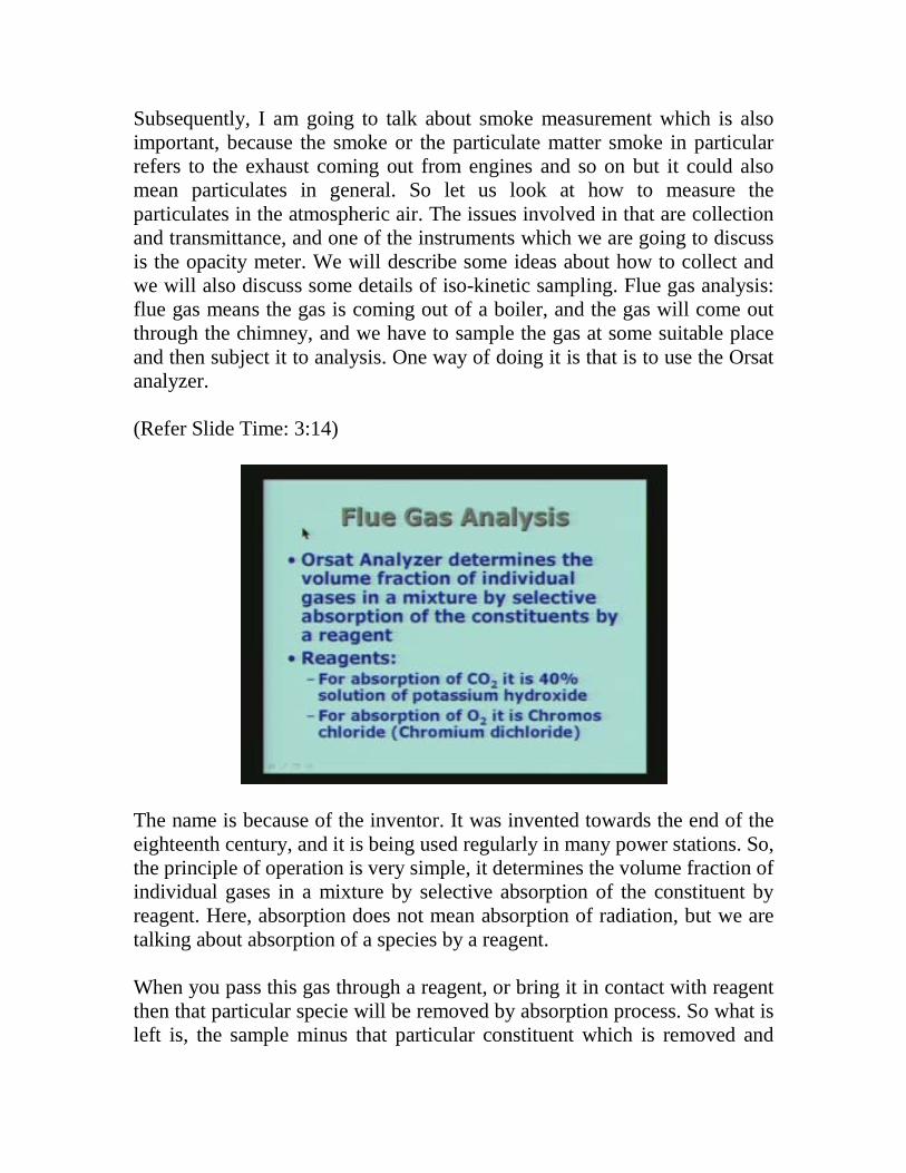
The name is because of the inventor. It was invented towards the end of the eighteenth century, and it is being used regularly in many power stations. So, the principle of operation is very simple, it determines the volume fraction of individual gases in a mixture by selective absorption of the constituent by reagent. Here, absorption does not mean absorption of radiation, but we are talking about absorption of a species by a reagent. When you pass this gas through a reagent, or bring it in contact with reagent then that particular specie will be removed by absorption process. So what is left is, the sample minus that particular constituent which is removed and
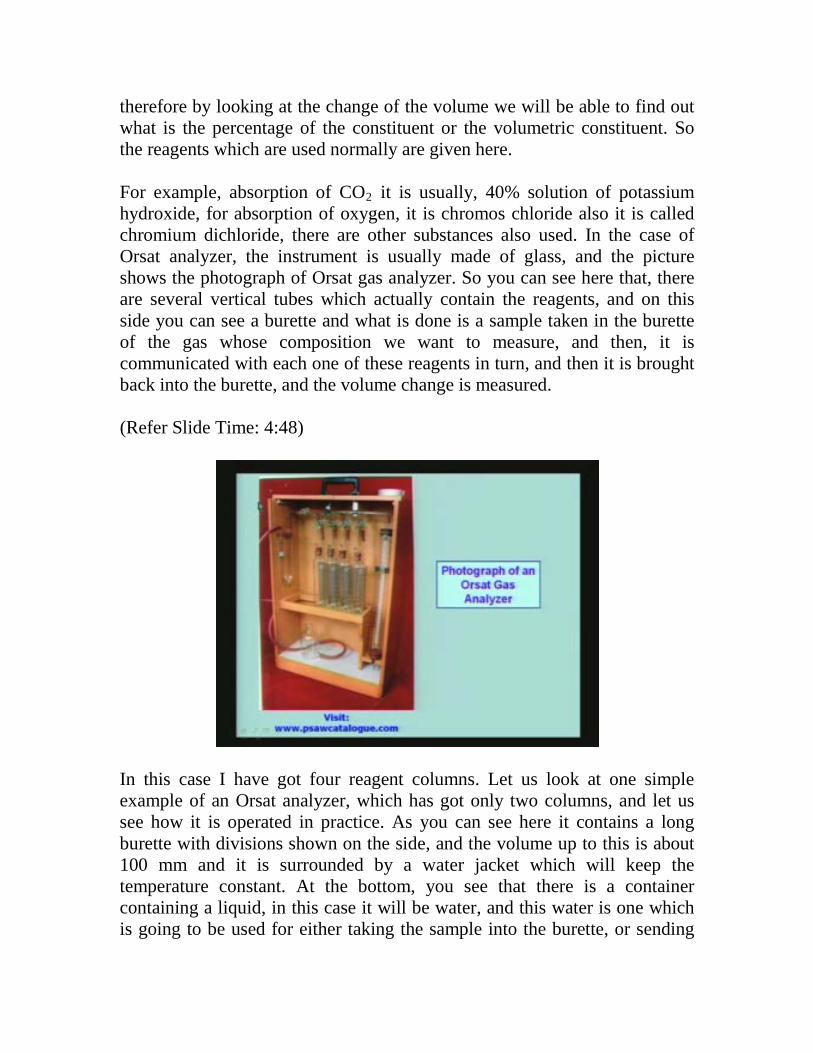
therefore by looking at the change of the volume we will be able to find out what is the percentage of the constituent or the volumetric constituent. So the reagents which are used normally are given here. For example, absorption of CO2 it is usually, 40% solution of potassium hydroxide, for absorption of oxygen, it is chromos chloride also it is called chromium dichloride, there are other substances also used. In the case of Orsat analyzer, the instrument is usually made of glass, and the picture shows the photograph of Orsat gas analyzer. So you can see here that, there are several vertical tubes which actually contain the reagents, and on this side you can see a burette and what is done is a sample taken in the burette of the gas whose composition we want to measure, and then, it is communicated with each one of these reagents in turn, and then it is brought back into the burette, and the volume change is measured. (Refer Slide Time: 4:48)
In this case I have got four reagent columns. Let us look at one simple example of an Orsat analyzer, which has got only two columns, and let us see how it is operated in practice. As you can see here it contains a long burette with divisions shown on the side, and the volume up to this is about 100 mm and it is surrounded by a water jacket which will keep the temperature constant. At the bottom, you see that there is a container containing a liquid, in this case it will be water, and this water is one which is going to be used for either taking the sample into the burette, or sending
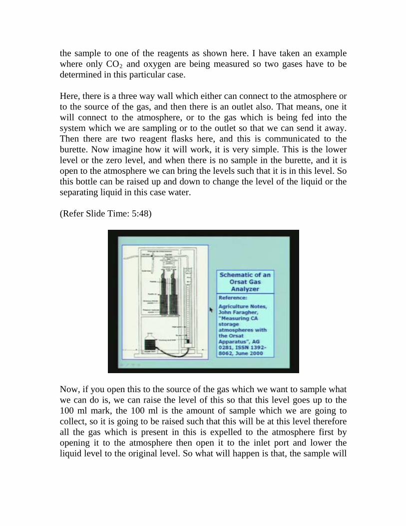
the sample to one of the reagents as shown here. I have taken an example where only CO2 and oxygen are being measured so two gases have to be determined in this particular case. Here, there is a three way wall which either can connect to the atmosphere or to the source of the gas, and then there is an outlet also. That means, one it will connect to the atmosphere, or to the gas which is being fed into the system which we are sampling or to the outlet so that we can send it away. Then there are two reagent flasks here, and this is communicated to the burette. Now imagine how it will work, it is very simple. This is the lower level or the zero level, and when there is no sample in the burette, and it is open to the atmosphere we can bring the levels such that it is in this level. So this bottle can be raised up and down to change the level of the liquid or the separating liquid in this case water. (Refer Slide Time: 5:48)
Now, if you open this to the source of the gas which we want to sample what we can do is, we can raise the level of this so that this level goes up to the 100 ml mark, the 100 ml is the amount of sample which we are going to collect, so it is going to be raised such that this will be at this level therefore all the gas which is present in this is expelled to the atmosphere first by opening it to the atmosphere then open it to the inlet port and lower the liquid level to the original level. So what will happen is that, the sample will
be drawn into this, because as you move the liquid down this vacant space which is created will take the sample and the sample will fill this. Usually the sample is taken one or two times or three times, and then it is sent out through the outlet hose so that we have flushed the entire burette plus the connecting tubes of the atmospheric air which should have been present to start with. So you first remove all the atmospheric air then finally you fill the entire thing with gas whose concentration or the species in that gas if you want to measure and this is closed. Of course, during the entire operation both these walls are closed. Suppose, we want to find out how much carbon dioxide by volume is present we will communicate it with this particular vessel here, and there is a mark here so the level of this fluid will be up to this mark. Now, what we do is, we transfer the gas by again raising this and by opening this wall the gas will be sent into this reagent container where the carbon dioxide will be absorbed by the potassium hydroxide solution. So allow enough time for it to come in contact with the potassium hydroxide by arranging such that this level is going to be at this level so that the entire 100 ml has gone into this reagent container. And then again, you bring it back and then the gas which has gone into this container will come back into this portion here. When it has gone into the reagent flask the carbon dioxide will be absorbed so whatever percentage of carbon dioxide is there in the sample it will be absorbed, therefore what comes out is only the rest of the gas. So what will happen is, when you bring it down this level will go to a higher level and of course, this will also be at a higher level because the volume of the gas will be lower by the amount of carbon dioxide which was present in the sample which has been absorbed by the reagent in this vessel. So you note down the reading here, and that will immediately give you this is 100, this is 0, and this will immediately give you the percentage by volume of the gas carbon dioxide in the mixture. Now we have to close this, and then open this and again transfer this gas to the other solution the chromos chloride solution which will absorb oxygen and then again do the same operation of bringing it back to this vessel or to the burette. Then you will see that there will be a further reduction in the volume and the difference between the previous reading and the subsequent reading will give you the percentage of oxygen by volume.
In this case, I have taken Orsat analyzer; one for carbon dioxide and one for oxygen so this will give you the idea about how much percentage of carbon dioxide is by volume, and how much is the percentage of oxygen by volume all at a constant temperature, because this entire thing is going to be surrounded by a water jacket at a constant temperature. So at constant temperature the percentage by volume will also be the molar percentage as we already know. This is a very simple instrument. Let us look at what the possibilities are. We are talking about very small percentage of carbon dioxide, if the combustion in the in the boiler furnace is more or less complete the amount of oxygen will be very small. In fact, this can be used for finding out how much excess oxygen is there because, whatever oxygen is not used in the combustion process is going to be present. Secondly, the carbon dioxide percentage will give us an idea about how much of carbon dioxide has formed in the reaction which has taken place in the combustion process. The third point is that, if the liquid contained here is water, then what will happen is the entire manifold here, and the burette and so on will be fully saturated with water vapor because, there is enough water available for that. Therefore the measurement is watched is called dry basis because we are not taking into account the moisture which is going to be present which is always there. So, even if moisture is present in the sample which we are going to measure, the water concentration is not going to be affecting the measurement therefore we call the measurement as dry basis. Let us now look at the other important problem which is important from many view points, one is of course, the atmospheric pollution point of view soot by smoke, and such particulate matter always give us problems because, they have implications for the health of the people, and also the visibility of the atmosphere is significantly affected by the presence of these particulates, and it will affect the operation of aircraft and things like that. There are different ways it can affect. It can also affect the weather because, the particles may create adverse conditions from the point of view of absorption of solar radiation, and things like that. Sometimes, the particles also come back to us as acid rain that is one of the major problems, and this acid rain is because of the gases which are present atmosphere. For example, sulfur dioxide and oxides of nitrogen and so on which are produced in large
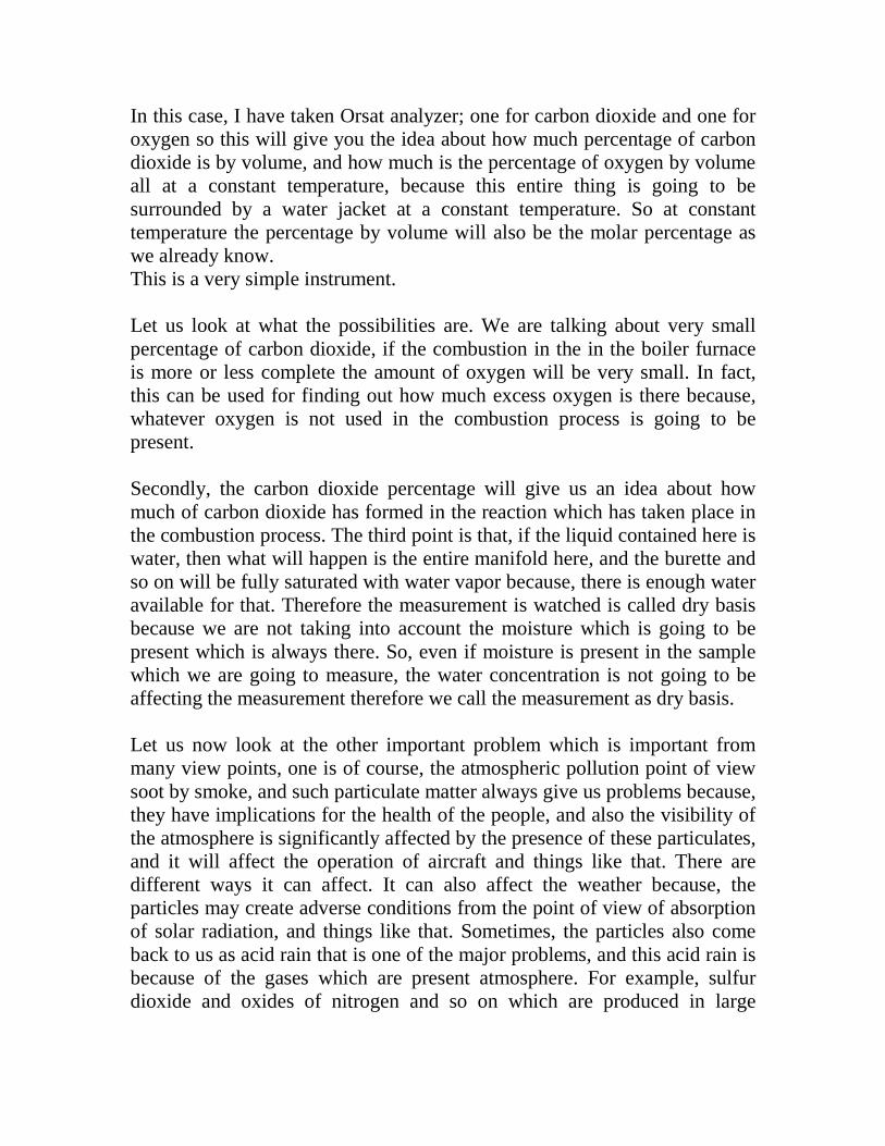
amount by power plants go out in atmosphere and they form particulate matter because of reactions with some suitable materials available in air. (Refer Slide Time: 14:03)
These particulates are also hazardous so we have to monitor the amount of particulates which are in the atmosphere. Therefore from this point of view, it is essential to know how to measure the particulates. There are several possibilities. The first thing to look at is the measurement of soot or smoke. Soot and smoke literally do not mean two different things but they are more or less the same thing. It is just the diameter of the particle which tells you whether it is a soot or smoke. In any combustion process, for example, if you take a diesel engine the exhaust contains lot of smoke, and you can you can very well see that because of the incomplete combustion of the hydrocarbon the unburnt carbon remains as particulate matter or particles and these come out of the tail pipe of the car if it is an automobile, or if it is a regular power plant it will come through the stack. So there are two things which are involved in this, two general ways of measuring the amount of soot or smoke. One is to measure by collecting the particles by a suitable method and then either by weighing the particles or measuring the transmittivity of a collector on which the particles are deposited.
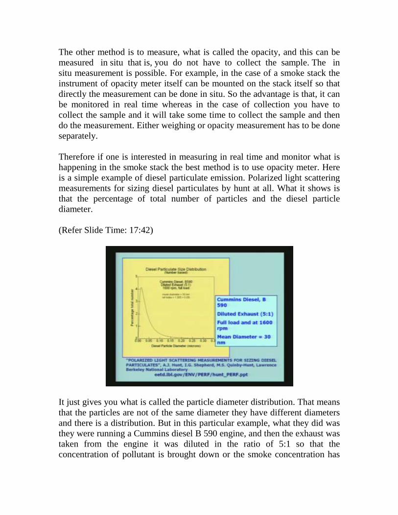
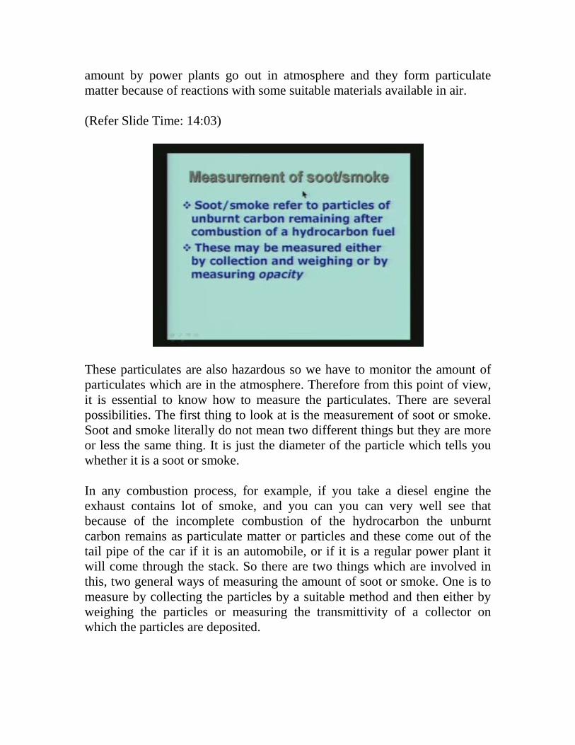
The other method is to measure, what is called the opacity, and this can be measured in situ that is, you do not have to collect the sample. The in situ measurement is possible. For example, in the case of a smoke stack the instrument of opacity meter itself can be mounted on the stack itself so that directly the measurement can be done in situ. So the advantage is that, it can be monitored in real time whereas in the case of collection you have to collect the sample and it will take some time to collect the sample and then do the measurement. Either weighing or opacity measurement has to be done separately. Therefore if one is interested in measuring in real time and monitor what is happening in the smoke stack the best method is to use opacity meter. Here is a simple example of diesel particulate emission. Polarized light scattering measurements for sizing diesel particulates by hunt at all. What it shows is that the percentage of total number of particles and the diesel particle diameter. (Refer Slide Time: 17:42)
It just gives you what is called the particle diameter distribution. That means that the particles are not of the same diameter they have different diameters and there is a distribution. But in this particular example, what they did was they were running a Cummins diesel B 590 engine, and then the exhaust was taken from the engine it was diluted in the ratio of 5:1 so that the concentration of pollutant is brought down or the smoke concentration has
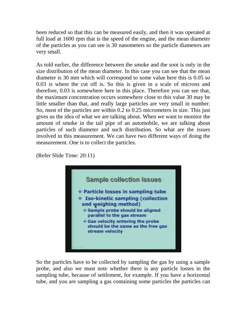
been reduced so that this can be measured easily, and then it was operated at full load at 1600 rpm that is the speed of the engine, and the mean diameter of the particles as you can see is 30 nanometers so the particle diameters are very small. As told earlier, the difference between the smoke and the soot is only in the size distribution of the mean diameter. In this case you can see that the mean diameter is 30 mm which will correspond to some value here this is 0.05 so 0.03 is where the cut off is. So this is given in a scale of microns and therefore, 0.03 is somewhere here in this place. Therefore you can see that, the maximum concentration occurs somewhere close to this value 30 may be little smaller than that, and really large particles are very small in number. So, most of the particles are within 0.2 to 0.25 micrometers in size. This just gives us the idea of what we are talking about. When we want to monitor the amount of smoke in the tail pipe of an automobile, we are talking about particles of such diameter and such distribution. So what are the issues involved in this measurement. We can have two different ways of doing the measurement. One is to collect the particles. (Refer Slide Time: 20:11)
So the particles have to be collected by sampling the gas by using a sample probe, and also we must note whether there is any particle losses in the sampling tube, because of settlement, for example. If you have a horizontal tube, and you are sampling a gas containing some particles the particles can
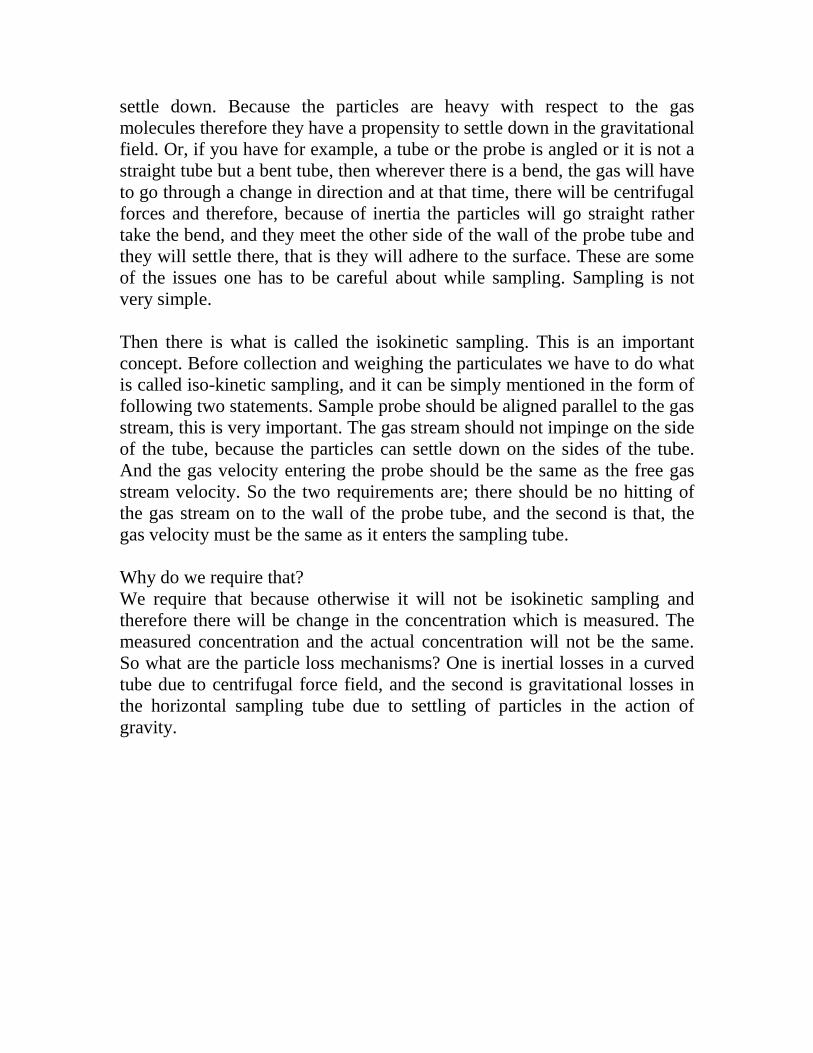
settle down. Because the particles are heavy with respect to the gas molecules therefore they have a propensity to settle down in the gravitational field. Or, if you have for example, a tube or the probe is angled or it is not a straight tube but a bent tube, then wherever there is a bend, the gas will have to go through a change in direction and at that time, there will be centrifugal forces and therefore, because of inertia the particles will go straight rather take the bend, and they meet the other side of the wall of the probe tube and they will settle there, that is they will adhere to the surface. These are some of the issues one has to be careful about while sampling. Sampling is not very simple. Then there is what is called the isokinetic sampling. This is an important concept. Before collection and weighing the particulates we have to do what is called iso-kinetic sampling, and it can be simply mentioned in the form of following two statements. Sample probe should be aligned parallel to the gas stream, this is very important. The gas stream should not impinge on the side of the tube, because the particles can settle down on the sides of the tube. And the gas velocity entering the probe should be the same as the free gas stream velocity. So the two requirements are; there should be no hitting of the gas stream on to the wall of the probe tube, and the second is that, the gas velocity must be the same as it enters the sampling tube. Why do we require that? We require that because otherwise it will not be isokinetic sampling and therefore there will be change in the concentration which is measured. The measured concentration and the actual concentration will not be the same. So what are the particle loss mechanisms? One is inertial losses in a curved tube due to centrifugal force field, and the second is gravitational losses in the horizontal sampling tube due to settling of particles in the action of gravity.
(Refer Slide Time: 22:48)
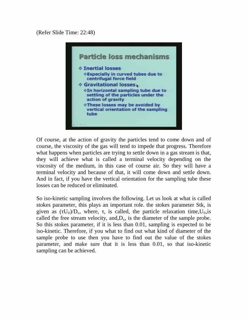
Of course, at the action of gravity the particles tend to come down and of course, the viscosity of the gas will tend to impede that progress. Therefore what happens when particles are trying to settle down in a gas stream is that, they will achieve what is called a terminal velocity depending on the viscosity of the medium, in this case of course air. So they will have a terminal velocity and because of that, it will come down and settle down. And in fact, if you have the vertical orientation for the sampling tube these losses can be reduced or eliminated. So iso-kinetic sampling involves the following. Let us look at what is called stokes parameter, this plays an important role. the stokes parameter Stk, is given as (τU0)/Ds, where, τ, is called, the particle relaxation time,U0,is called the free stream velocity, and,Ds, is the diameter of the sample probe. So this stokes parameter, if it is less than 0.01, sampling is expected to be iso-kinetic. Therefore, if you what to find out what kind of diameter of the sample probe to use then you have to find out the value of the stokes parameter, and make sure that it is less than 0.01, so that iso-kinetic sampling can be achieved.
(Refer Slide Time: 23:46)
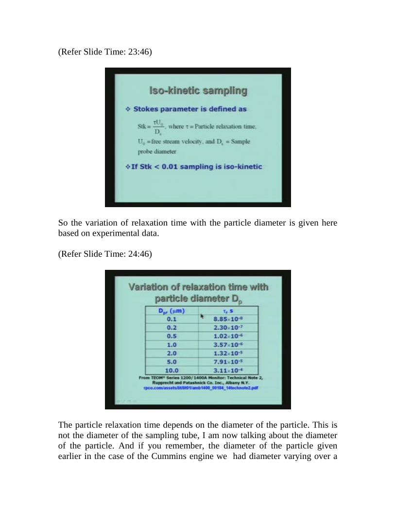
So the variation of relaxation time with the particle diameter is given here based on experimental data. (Refer Slide Time: 24:46)
The particle relaxation time depends on the diameter of the particle. This is not the diameter of the sampling tube, I am now talking about the diameter of the particle. And if you remember, the diameter of the particle given earlier in the case of the Cummins engine we had diameter varying over a
certain range. So here, we have taken the normal range of diameters which are useful in practice, and I have gone from 0.1 to 10 micrometers these are very large particles, and these are relatively smaller particles and this is the kind of particles we talked about when we were talking about the diesel engines. So you see that the relaxation time is very small about 10 nanoseconds here, and then progressively here it is about one tenth of millisecond. This relaxation time has something to do with the iso-kinetic sampling we require that stokes parameter to be less than 0.01, and this relaxation time goes into that formula. Let us look at typical type of situation which will prevail. (Refer Slide Time: 26:15)
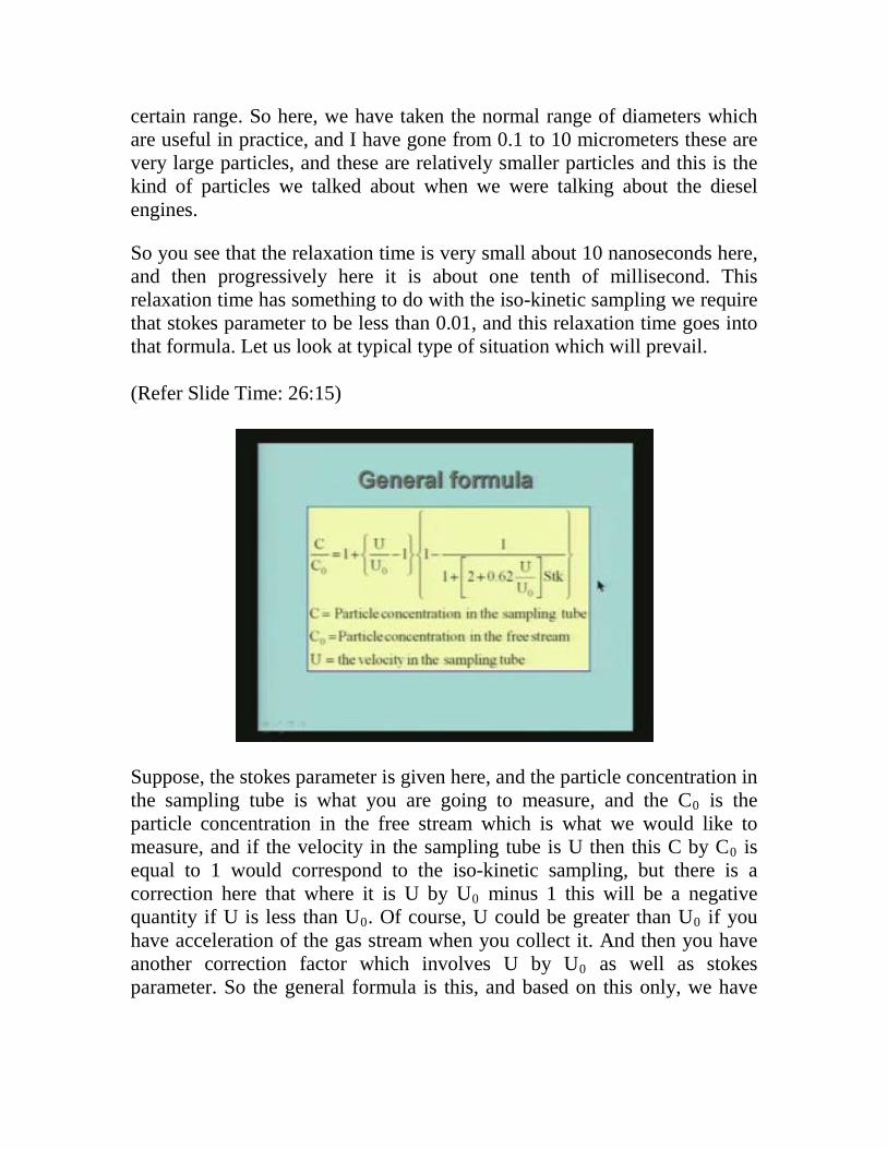
Suppose, the stokes parameter is given here, and the particle concentration in the sampling tube is what you are going to measure, and the C0 is the particle concentration in the free stream which is what we would like to measure, and if the velocity in the sampling tube is U then this C by C0 is equal to 1 would correspond to the iso-kinetic sampling, but there is a correction here that where it is U by U0 minus 1 this will be a negative quantity if U is less than U0. Of course, U could be greater than U0 if you have acceleration of the gas stream when you collect it. And then you have another correction factor which involves U by U0 as well as stokes parameter. So the general formula is this, and based on this only, we have
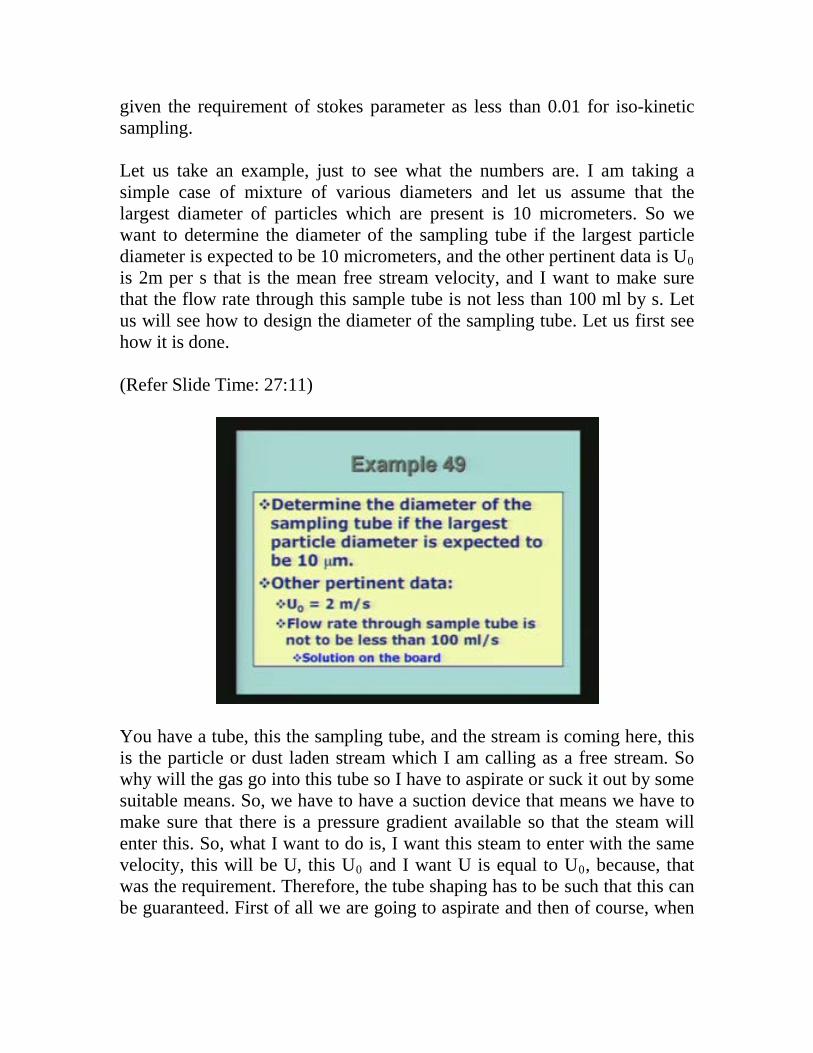
given the requirement of stokes parameter as less than 0.01 for iso-kinetic sampling. Let us take an example, just to see what the numbers are. I am taking a simple case of mixture of various diameters and let us assume that the largest diameter of particles which are present is 10 micrometers. So we want to determine the diameter of the sampling tube if the largest particle diameter is expected to be 10 micrometers, and the other pertinent data is U0 is 2m per s that is the mean free stream velocity, and I want to make sure that the flow rate through this sample tube is not less than 100 ml by s. Let us will see how to design the diameter of the sampling tube. Let us first see how it is done. (Refer Slide Time: 27:11)
You have a tube, this the sampling tube, and the stream is coming here, this is the particle or dust laden stream which I am calling as a free stream. So why will the gas go into this tube so I have to aspirate or suck it out by some suitable means. So, we have to have a suction device that means we have to make sure that there is a pressure gradient available so that the steam will enter this. So, what I want to do is, I want this steam to enter with the same velocity, this will be U, this U0 and I want U is equal to U0, because, that was the requirement. Therefore, the tube shaping has to be such that this can be guaranteed. First of all we are going to aspirate and then of course, when
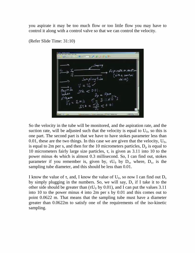
you aspirate it may be too much flow or too little flow you may have to control it along with a control valve so that we can control the velocity. (Refer Slide Time: 31:10)
So the velocity in the tube will be monitored, and the aspiration rate, and the suction rate, will be adjusted such that the velocity is equal to U0, so this is one part. The second part is that we have to have stokes parameter less than 0.01, these are the two things. In this case we are given that the velocity, U0, is equal to 2m per s, and then for the 10 micrometers particles, Dp is equal to 10 micrometers fairly large size particles, τ, is given as 3.11 into 10 to the power minus 4s which is almost 0.3 millisecond. So, I can find out, stokes parameter if you remember is, given by, τU0 by Ds, where, Ds, is the sampling tube diameter, and this should be less than 0.01. I know the value of τ, and, I know the value of U0, so now I can find out Ds by simply plugging in the numbers. So, we will say, Ds if I take it to the other side should be greater than (τU0 by 0.01), and I can put the values 3.11 into 10 to the power minus 4 into 2m per s by 0.01 and this comes out to point 0.0622 m. That means that the sampling tube must have a diameter greater than 0.0622m to satisfy one of the requirements of the iso-kinetic sampling.
(Refer Slide Time: 32:02)
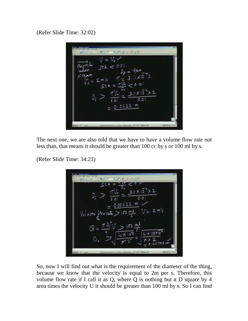
The next one, we are also told that we have to have a volume flow rate not less than, that means it should be greater than 100 cc by s or 100 ml by s. (Refer Slide Time: 34:21)
So, now I will find out what is the requirement of the diameter of the thing, because we know that the velocity is equal to 2m per s. Therefore, this volume flow rate if I call it as Q, where Q is nothing but π D square by 4 area times the velocity U it should be greater than 100 ml by s. So I can find
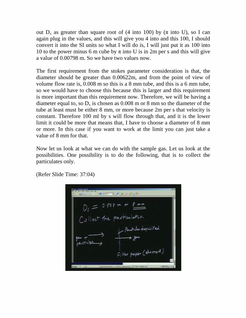
out Ds as greater than square root of (4 into 100) by (π into U), so I can again plug in the values, and this will give you 4 into and this 100, I should convert it into the SI units so what I will do is, I will just put it as 100 into 10 to the power minus 6 m cube by π into U is in 2m per s and this will give a value of 0.00798 m. So we have two values now. The first requirement from the stokes parameter consideration is that, the diameter should be greater than 0.00622m, and from the point of view of volume flow rate is, 0.008 m so this is a 8 mm tube, and this is a 6 mm tube, so we would have to choose this because this is larger and this requirement is more important than this requirement now. Therefore, we will be having a diameter equal to, so Ds is chosen as 0.008 m or 8 mm so the diameter of the tube at least must be either 8 mm, or more because 2m per s that velocity is constant. Therefore 100 ml by s will flow through that, and it is the lower limit it could be more that means that, I have to choose a diameter of 8 mm or more. In this case if you want to work at the limit you can just take a value of 8 mm for that. Now let us look at what we can do with the sample gas. Let us look at the possibilities. One possibility is to do the following, that is to collect the particulates only. (Refer Slide Time: 37:04)
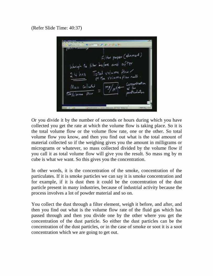
For example, if I have a filter paper, or some material and I am having the gas plus particles so the gas will pass through, and the particles will deposit. The particles get deposited on the filter paper. Of course, filter paper means it could be some filtering element, but if the diameters are very small, filter paper will not do that, then we will have to go for a suitable material and usually they are called as molecular sieves. That means that the gas only will pass through, and even very fine particles will deposit on the filter element. So we can say filter paper or filter element. These filter elements are usually made of material which will withstand the type of situation which we are having here. There are two ways of using this. One way is to weigh the filter before and after collection. Before collection we know the weight of the filter element, and then after collection we find out what is the weight of the filter element and then the difference must give the amount of material which has been collected. Now the point is, if you want significant amount of material to be collected so that you can do an accurate measurement of the mass, we require a large amount of time. For example, in typical cases it may be about 24 hrs. You collect the material for about 24 hrs, and then to start with you have weighed the filter element, and after enough material is collected over a period of 24 hours, we can weigh it and then we can find out how much of the gas has passed through that system. So, in 24 hours what is the total volume flow is easy to measure because we know the velocity of the fluid in the sampling tube, we know the area of cross section of the tube and we know the amount of time for which we have conducted this collection of particles, so we can actually find out the total volume flow.
(Refer Slide Time: 40:37)
Or you divide it by the number of seconds or hours during which you have collected you get the rate at which the volume flow is taking place. So it is the total volume flow or the volume flow rate, one or the other. So total volume flow you know, and then you find out what is the total amount of material collected so if the weighing gives you the amount in milligrams or micrograms or whatever, so mass collected divided by the volume flow if you call it as total volume flow will give you the result. So mass mg by m cube is what we want. So this gives you the concentration. In other words, it is the concentration of the smoke, concentration of the particulates. If it is smoke particles we can say it is smoke concentration and for example, if it is dust then it could be the concentration of the dust particle present in many industries, because of industrial activity because the process involves a lot of powder material and so on. You collect the dust through a filter element, weigh it before, and after, and then you find out what is the volume flow rate of the fluid gas which has passed through and then you divide one by the other where you get the concentration of the dust particle. So either the dust particles can be the concentration of the dust particles, or in the case of smoke or soot it is a soot concentration which we are going to get out.
Let us look at another way of doing it as the following. You have collected the sample on the filter element, and I can measure the optical transmittance. In fact, there are many other interesting ways of doing it. For example; the dust particles or the soot particles have been collected on the filter element. We can compare this visually with a sample way of known density of particles deposited on along the filter paper which can be taken as a reference. So, if you have several references with different amounts of dust particles being present, I can just compare and find out which is closest to that visually and immediately say that this is like this particular concentration, so that is one possibility that is by comparison with a standard concentration obtained by comparing with a standard. (Refer Slide Time: 45:31)
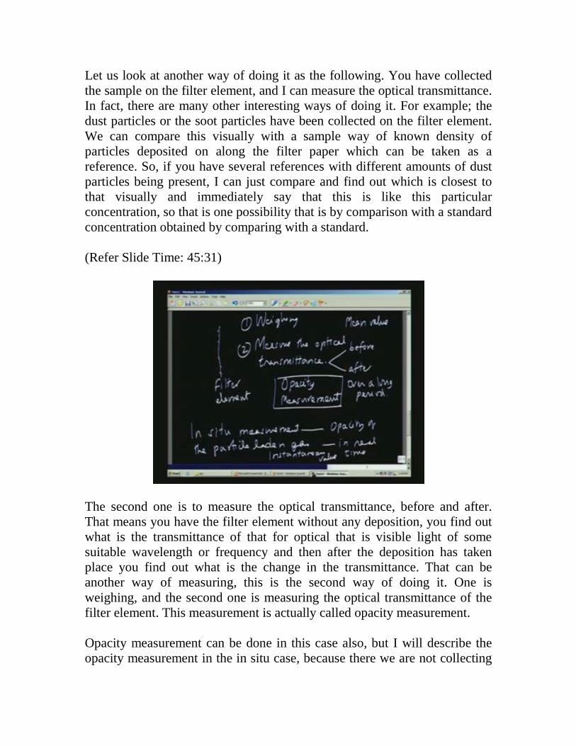
The second one is to measure the optical transmittance, before and after. That means you have the filter element without any deposition, you find out what is the transmittance of that for optical that is visible light of some suitable wavelength or frequency and then after the deposition has taken place you find out what is the change in the transmittance. That can be another way of measuring, this is the second way of doing it. One is weighing, and the second one is measuring the optical transmittance of the filter element. This measurement is actually called opacity measurement. Opacity measurement can be done in this case also, but I will describe the opacity measurement in the in situ case, because there we are not collecting
the material. Here we have a filter element, and what you do is you put the filter element in the path of a light beam, and find out what is the transmittance before and after you get the opacity. But this opacity is now related to the total amount of material which has been collected over a given amount of time. Therefore you have to relate it to the concentration of the dust or the gas particles or the particulates in the original gas sample by using a little bit of algebra. The other method is, in situ measurement which again uses opacity measurement but not opacity of the filter element but it uses the opacity of the particle laden gas itself. So this becomes in real time, this is not real time because this is going to be over a long period. In a way this also gives you the average or the mean value whereas this gives you the instantaneous value in real time or instantaneous. So what is the difference between these? Mean value means, over a period of 24 hours for example you are collecting the sample or collecting the sample on the filter element. Throughout that 24 hrs it may not be the same concentration as concentrations vary. Sometimes the concentration might have gone up, sometimes the concentration must have gone down so what we will get over a 24 hr period is the mean value from this but suppose I want to know what is the rate at which it is produced over a period of time and how it varies with time I can only do by the in situ measurement. So the in situ measurement is useful when you want to do it in real time. To look at it in more detail we are going to use a smoke opacity meter.
(Refer Slide Time: 45:36)
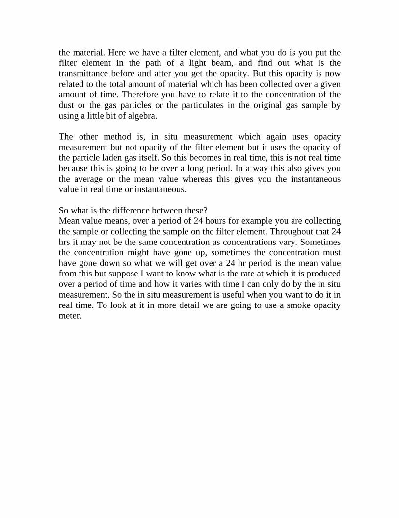
The smoke opacity meter consists of a transmitter of light then you have a receiver, and in between these two stations you must have the gas which is having particulates that will pass through. So the light which is leaving this source gets attenuated, because of its passage through the dusty atmosphere or the smoke and then it is measured by this receiver which is usually a photo detector, and measuring the amount of light leaving here, and what is received here, we can find out what is the opacity of the intervening medium and of course, we know what is the length of the travel of light through the particle laden or smoky gas. For example, this can be connected right at the exit of the chimney or the stack and you can measure the concentration in situ. In the new terminology, opacity is defined as something which is nothing but, this we will call it, O, so it will be 1 minus (light transmitted by light emitted) by the source. What I am thinking of is I have got a source of light here so let us assume that the intensity of light is I, and I have the receiver here or the detector this is the photo detector, and the path length is L, between the two stations, and what is reaching here is It, so this is your It, and this your I which is leaving.
(Refer Slide Time: 49:35)
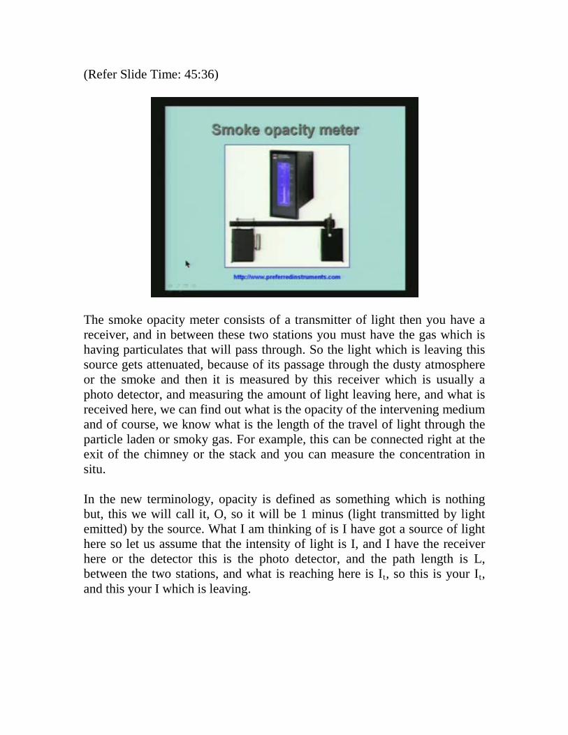
So opacity is nothing but, 1 minus (light transmitted by light emitted). In other words, this is what is available at the photo detector that means that much has reached this place so this is the transmitted amount. It is nothing but 1 minus the transmittance, so we can also define it as 1 minus tau,1 minus transmittance so we will say it is also equal to 1 minus transmittance. So what is measured is the ratio of these two, and then you find out what is the opacity and the opacity can be a measure of the amount or concentration of the particulate. How does it come about? Let us look at the relationship between the It and I. This is given by exponential according to the absorption and the scattering of particles because of the absorption and scattering the intensity will be reduced, and the ratio is given by exponential [minus beta times L] where beta we call it as extinction coefficient. This is known as Beer’s law which is already familiar to us.
(Refer Slide Time: 50:31)
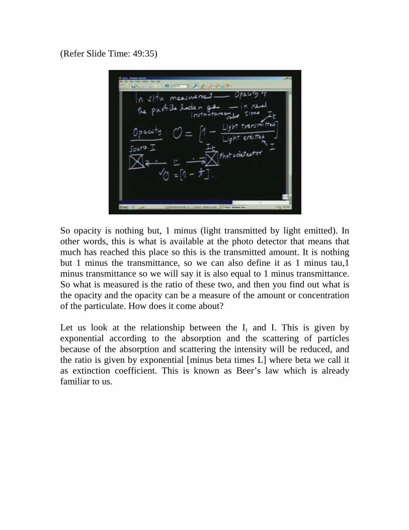
So this extinction coefficient beta is due to two reasons. One is absorption, and the second one is, due to scattering. Therefore, these two together is the reason for reduction in the amount of light reaching the detector. That means that, It is less than I, because of absorption by the medium and the scattering in the medium. (Refer Slide Time: 52:17)
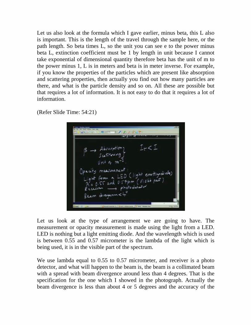
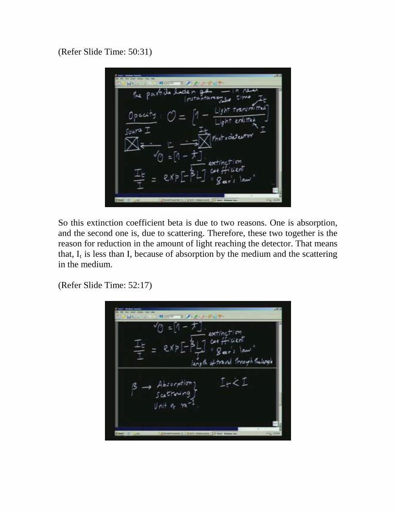
Let us also look at the formula which I gave earlier, minus beta, this L also is important. This is the length of the travel through the sample here, or the path length. So beta times L, so the unit you can see e to the power minus beta L, extinction coefficient must be 1 by length in unit because I cannot take exponential of dimensional quantity therefore beta has the unit of m to the power minus 1, L is in meters and beta is in meter inverse. For example, if you know the properties of the particles which are present like absorption and scattering properties, then actually you find out how many particles are there, and what is the particle density and so on. All these are possible but that requires a lot of information. It is not easy to do that it requires a lot of information. (Refer Slide Time: 54:21)
Let us look at the type of arrangement we are going to have. The measurement or opacity measurement is made using the light from a LED. LED is nothing but a light emitting diode. And the wavelength which is used is between 0.55 and 0.57 micrometer is the lambda of the light which is being used, it is in the visible part of the spectrum. We use lambda equal to 0.55 to 0.57 micrometer, and receiver is a photo detector, and what will happen to the beam is, the beam is a collimated beam with a spread with beam divergence around less than 4 degrees. That is the specification for the one which I showed in the photograph. Actually the beam divergence is less than about 4 or 5 degrees and the accuracy of the
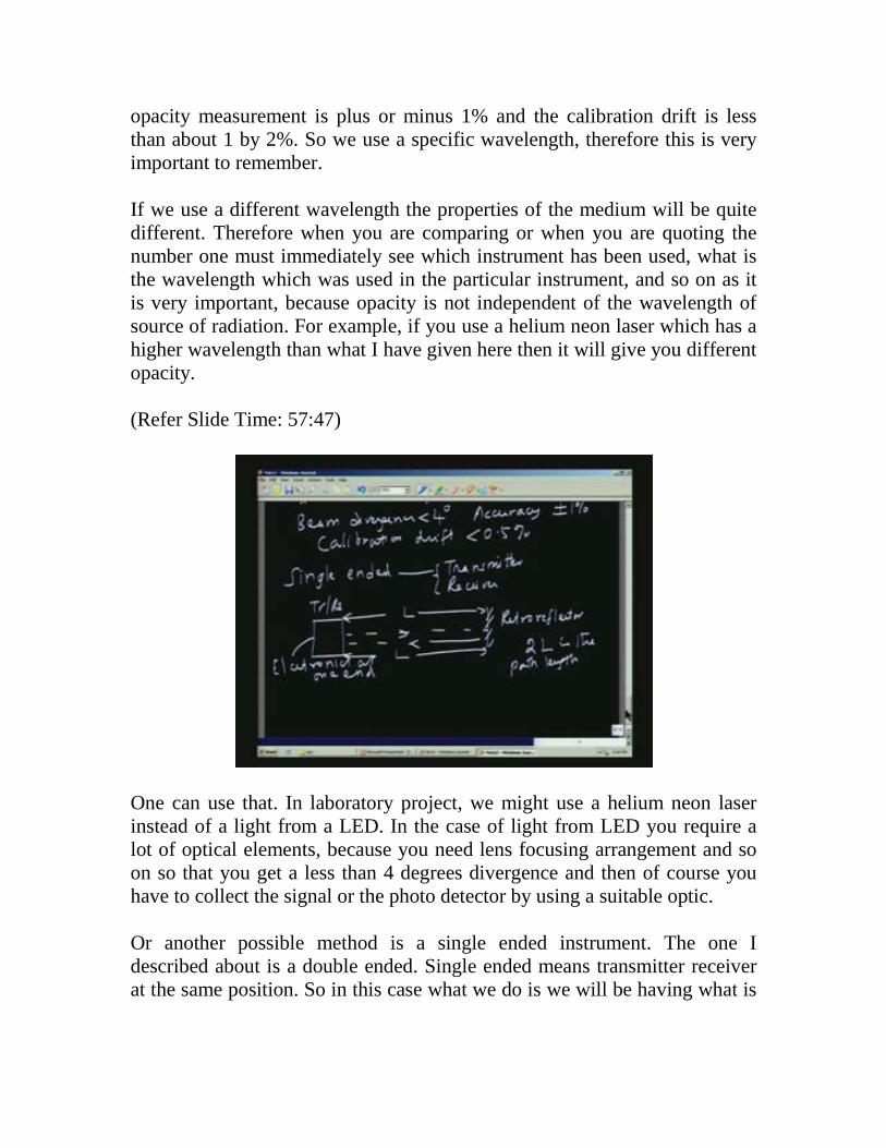
opacity measurement is plus or minus 1% and the calibration drift is less than about 1 by 2%. So we use a specific wavelength, therefore this is very important to remember. If we use a different wavelength the properties of the medium will be quite different. Therefore when you are comparing or when you are quoting the number one must immediately see which instrument has been used, what is the wavelength which was used in the particular instrument, and so on as it is very important, because opacity is not independent of the wavelength of source of radiation. For example, if you use a helium neon laser which has a higher wavelength than what I have given here then it will give you different opacity. (Refer Slide Time: 57:47)
One can use that. In laboratory project, we might use a helium neon laser instead of a light from a LED. In the case of light from LED you require a lot of optical elements, because you need lens focusing arrangement and so on so that you get a less than 4 degrees divergence and then of course you have to collect the signal or the photo detector by using a suitable optic. Or another possible method is a single ended instrument. The one I described about is a double ended. Single ended means transmitter receiver at the same position. So in this case what we do is we will be having what is
called a Retroreflector. You have the transmitter receiver and then it goes here and we have essentially a mirror so we call it as retroreflector. Retroreflector is one which will reflect it back in the same direction independent of the incident direction; independent of the orientation of the reflector itself it will go back. So it is the forward beam and the backward beam we are just retracing the path. There are two advantages; one is, this is L, this is also L so 2L is the path length. So we get an advantage in terms of the amount of path length available and therefore it passes through the gas sample twice and therefore the optical path length is increased. Of course, the transmission and receiver is done at the same place and therefore you can have all the measuring part and the electronics can be at one end everything can be at one end so that is the advantage of this instrument. Thank you.