2007/2008 international mechanical code … international mechanical code committee ... american...
TRANSCRIPT
2008 ICC PUBLIC HEARING RESULTS 401
2007/2008 INTERNATIONAL MECHANICAL CODE COMMITTEE
Edmund Velaski, Sr., CBO—Chair Chief Mechanical Inspector City of Mobile Mobile, AL Billy G. Hinton, Jr.—Vice Chair Code Official North Carolina Department of Insurance- Engineering Division Raleigh, NC John R. Addario, PE Senior Building Construction Engineer NYS Department of State Code Enforcement & Administration Albany, NY Wm. Scott Copp Director of Building Town of Perinton Fairport, NY William Ivey President. Ivey Engineering, Inc. San Diego, CA Dennis Martinelli Supervising Combination Inspector Fairfax County Fairfax, VA David McMillan, CBO Chief Building Official City of San Marcos San Marcos, TX Rep: City of San Marcos and Capital Building Officials Association Carl J. Opatrny Building Official City of Independence
Mark Riley Inspector Supervisor City of Troy Troy, MI John Sedine President Engineered Heating & Cooling Grand Rapids, MI Rep: Air Conditioning Contractors of America (ACCA) Walter J. Sperko President, Sperko Engineering Services, Inc. Greensboro, NC Rep: American Society of Mechanical Engineers (ASME) & Mechanical Contractors Association of America (MCAA) Charles Szollosy Principal CS Consulting Engineers Rockville, MD John K. Taecker, PE Senior Staff Engineer Underwriters Laboratories Inc. San Jose, CA Dwight Williams, CBO, MCP Plan Examiner Safebuilt Georgia Canton, GA Rep: City of Johns Creek, GA Staff Secretary: Larry Simpson, PE Sr. Staff Engineer International Code Council
Independence, OH
402 2008 ICC PUBLIC HEARING RESULTS
2008 ICC PUBLIC HEARING RESULTS 403
INTERNATIONAL MECHANICAL CODE COMMITTEE HEARING RESULTS
M1-07/08 Committee Action: Disapproved Committee Reason: The action was based on the proponent’s request for disapproval because of a possible duplication with other administrative requirements. Assembly Action: None M2-07/08 Committee Action: Approved as Submitted Committee Reason: The additional phrase makes the definition consistent with the IBC definition. Assembly Action: None
M3-07/08 Committee Action: Approved as Modified Modify proposal as follows: HOOD. An air intake device used to capture by entrapment, impingement, adhesion or similar means, grease, moisture, hot air heat and similar contaminants before they enter a duct system.
Type I. A kitchen hood for collecting and removing grease vapors and smoke. Such hoods are equipped with a fire suppression system.
Type II. A general kitchen hood for collecting and removing steam, vapor, heat, and odors and products of combustion.
Committee Reason: This proposal makes the definition consistent with the definition in ASHRAE 154 and further clarifies that Type II hoods must also remove products of combustion. The modification replaces “hot air” with the more correct term “heat” and also puts the terms “vapor” and “odor” back into the definition of Type II hoods because there was no justification offered for removing them from the original language. Assembly Action: None M4-07/08 Committee Action: Approved as Submitted Committee Reason: This is an undefined term in the code that needs to be defined. The user will have a better understanding of what the interlocking of two devices involves. Assembly Action: None M5-07/08 Committee Action: Approved as Submitted Committee Reason: The term “conveyor oven” appears in both this definition and that of Medium Duty Cooking Appliances and is more appropriate for Medium Duty. That term is deleted and the new term “countertop conveyorized baking/finishing ovens” is added to include cooking appliances that are prevalent in sandwich shops. Assembly Action: None
404 2008 ICC PUBLIC HEARING RESULTS
M6-07/08 PART I IMC Committee Action: Disapproved Committee Reason: Intake opening locations are already appropriately covered in Section 401.4. There is no reason to duplicate the requirements in this section. Assembly Action: None PART II IRC Committee Action: Disapproved Committee Reason: The proposed intake opening requirements are adequately covered in other sections of the code and the manufacturer’s installation instructions. Assembly Action: None
M7-07/08 PART I IMC Withdrawn by Proponent PART II IPC Withdrawn by Proponent PART III IFGC Withdrawn by Proponent
M8-07/08 Committee Action: Approved as Submitted Committee Reason: The language that was relocated to a new section is unrelated to the elevation of appliances which is the subject of the rest of the section. It should be in its own section. Assembly Action: None
M9-07/08 PART I IMC Committee Action: Approved as Submitted Committee Reason: A minimum height above grade is needed in the code and this change adds a 3 inch height which is consistent with the IRC requirement. Assembly Action: None PART II IRC Committee Action: Approved as Submitted Committee Reason: This code change combines two sections to put all of the ground clearance requirements in one place. Assembly Action: None PART III IFGC Committee Action: Disapproved Committee Reason: The parallel code text in the IMC and IRC contains a requirement for compliance with the manufacturer’s instructions which is not proposed for the IFGC text. There are pads being successfully used in the field that are less than 3 inches in height above grade. Assembly Action: None
2008 ICC PUBLIC HEARING RESULTS 405
M10-07/08 PART I IMC Committee Action: Disapproved Committee Reason: The committee preferred the language in M11-07/08, Part I. Assembly Action: None PART II IRC Committee Action: Approved as Submitted Committee Reason: Section M1305.1 already requires access for mechanical equipment and appliances. The stricken language is redundant. Assembly Action: None
M11-07/08 PART I IMC Committee Action: Approved as Modified Modify proposal as follows: 306.5 (Supp) Equipment and appliances on roofs or elevated structures. Where equipment requiring access and appliances are installed on roofs or elevated structures at a height exceeding 16 feet (4877 mm), such access shall be provided by a permanent approved means of access, the extent of which shall be from grade or floor level to the equipment and appliances’ level service space. Such access shall not require climbing over obstructions greater than 30 inches (762 mm) high or walking on roofs having a slope greater than four units vertical in 12 units horizontal (33-percent slope). Where access involves climbing over parapet walls, the height shall be measured to the top of the parapet wall. Permanent ladders installed to provide the required access shall comply with the following minimum design criteria:
1. The side railing shall extend above the parapet or roof edge not less than 30 inches (762 mm). 2. Ladders shall have rung spacing not to exceed 14 inches (356 mm) on center. 3. Ladders shall have a toe spacing not less than 6 inches (152 mm) deep. 4. There shall be a minimum of 18 inches (457 mm) between rails. 5. Rungs shall have a minimum 0.75-inch (19 mm) diameter and be capable of withstanding a 300-pound
(136.1 kg) load. 6. Ladders over 30 feet (9144 mm) in height shall be provided with offset sections and landings capable of
withstanding100 pounds (488.2 kg/m2) per square foot. Landing dimensions shall be not less than 18 inches and not less than the width of the ladder served. A guard rail shall be provided on all open sides of the landing.
7. Ladders shall be protected against corrosion by approved means. Catwalks installed to provide the required access shall be not less than 24 inches (610 mm) wide and shall
have railings as required for service platforms.
Exception: This section shall not apply to Group R-3 occupancies. (Portions of proposal not shown remain unchanged) Committee Reason: This proposal clarifies that all equipment and appliances need access. The modification adds “requiring access” after “equipment” because not all elevated equipment requires access. Assembly Action: None PART II IRC Committee Action: Approved as Submitted Committee Reason: This proposal is identical to M10, Part II and the action by the committee is consistent with its action on M10. Assembly Action: None
406 2008 ICC PUBLIC HEARING RESULTS
M12-07/08 Committee Action: Disapproved Committee Reason: There was concern that alternating tread devices will not provide an adequate level of safety for service technicians trying to access elevated equipment and appliances while carrying tools and repair parts. The code official can already approve these devices in accordance with the first sentence of this section. Assembly Action: None
M13-07/08 Committee Action: Disapproved Committee Reason: The new language would apply to dwellings in high-rise apartment buildings and equipment and appliances on the roofs of such buildings need to have access whether it was previously provided or not. Assembly Action: None M14-07/08 Committee Action: Disapproved Committee Reason: There was no evidence presented to indicate that there is a safety problem with the current ladder requirements. The handrail height in Item 1 creates confusion by citing both 30 inches above the roof and 36 inches in handrail height. Assembly Action: None
M15-07/08 Committee Action: Approved as Modified Modify proposal as follows: 307.2.3 Auxiliary and secondary drain systems. In addition to the requirements of Section 307.2.1, where damage to any building components will could occur as a result of overflow from the equipment primary condensate removal system, one of the following auxiliary protection methods shall be provided for each cooling coil or fuel-fired appliance that produces condensate:
1. An auxiliary drain pan with a separate drain shall be provided under the coils on which condensation will occur. The auxiliary pan drain shall discharge to a conspicuous point of disposal to alert occupants in the event of a stoppage of the primary drain. The pan shall have a minimum depth of 1.5 inches (38 mm), shall not be less than 3 inches (76 mm) larger than the unit or the coil dimensions in width and length and shall be constructed of corrosion-resistant material. Metallic pans shall have a minimum thickness of not less than 0.0276-inch (0.7 mm) galvanized sheet metal. Nonmetallic pans shall have a minimum thickness of not less than 0.0625 inch (1.6 mm).
2. A separate overflow drain line shall be connected to the drain pan provided with the equipment. Such overflow drain shall discharge to a conspicuous point of disposal to alert occupants in the event of a stoppage of the primary drain. The overflow drain line shall connect to the drain pan at a higher level than the primary drain connection.
3. An auxiliary drain pan without a separate drain line shall be provided under the coils on which condensate will occur. Such pan shall be equipped with a water-level detection device conforming to UL 508 that will shut off the equipment served prior to overflow of the pan. The auxiliary drain pan shall be constructed in accordance with Item 1 of this section.
4. A water level detection device conforming to UL 508 shall be provided that will shut off the equipment served in the event that the primary drain is blocked. The device shall be installed in the primary drain line, the overflow drain line, or in the equipment-supplied drain pan, located at a point higher than the primary drain line connection and below the overflow rim of such pan.
Exception: Fuel-fired appliances that automatically shut down operation in the event of a stoppage in the condensate drainage system.
2008 ICC PUBLIC HEARING RESULTS 407
Committee Reason: The original language in the charging section requires a pan to be included in the protection method, but Item 4 allows a method without a pan. This change deletes the pan requirement and corrects the language to include all four methods. The modification clarifies that the auxiliary protection methods are required where the primary system fails. Assembly Action: None
M16-07/08 PART I IMC Committee Action: Approved as Modified Modify proposal as follows: 307.2.3 Auxiliary and secondary drain systems. In addition to the requirements of Section 307.2.1, a secondary drain or auxiliary drain pan shall be required for each cooling or evaporator coil or fuel-fired appliance that produces condensate, where damage to any building components will occur as a result of overflow from the equipment drain pan or stoppage in the condensate drain piping. One of the following methods shall be used: 1. An auxiliary drain pan with a separate drain shall be provided under the coils on which condensation will occur. The auxiliary pan drain shall discharge to a conspicuous point of disposal to alert occupants in the event of a stoppage of the primary drain. The pan shall have a minimum depth of 1.5 inches (38 mm), shall not be less than 3 inches (76 mm) larger than the unit or the coil dimensions in width and length and shall be constructed of corrosion-resistant material. Galvanized sheet steel pans shall have a minimum thickness of not less than 0.0236-inch (0.6010 mm) (No. 24 gage) galvanized sheet metal. Nonmetallic pans shall have a minimum thickness of not less than 0.0625-inch (1.6 mm). 2. A separate overflow drain line shall be connected to the drain pan provided with the equipment. Such overflow drain shall discharge to a conspicuous point of disposal to alert occupants in the event of a stoppage of the primary drain. The overflow drain line shall connect to the drain pan at a higher level than the primary drain connection. 3. An auxiliary drain pan without a separate drain line shall be provided under the coils on which condensate will occur. Such pan shall be equipped with a water-level detection device conforming to UL 508 that will shut off the equipment served prior to overflow of the pan. The auxiliary drain pan shall be constructed in accordance with Item 1 of this section. 4. A water level detection device conforming to UL 508 shall be provided that will shut off the equipment served in the event that the primary drain is blocked. The device shall be installed in the primary drain line, the overflow drain line, or in the equipment-supplied drain pan, located at a point higher than the primary drain line connection and below the overflow rim of such pan.
Exception: Fuel-fired appliances that automatically shut down operation in the event of a stoppage in the condensate drainage system.
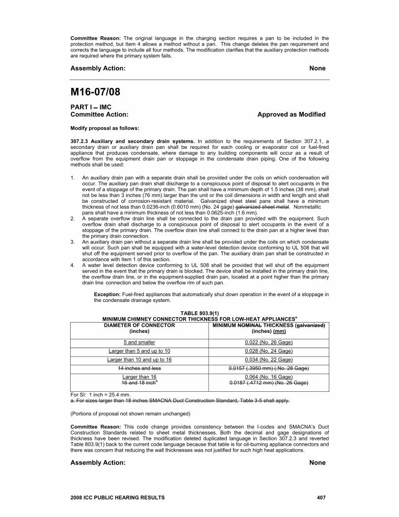
TABLE 803.9(1)
MINIMUM CHIMNEY CONNECTOR THICKNESS FOR LOW-HEAT APPLIANCESa DIAMETER OF CONNECTOR
(inches) MINIMUM NOMINAL THICKNESS (galvanized)
(inches) (mm)
5 and smaller 0.022 (No. 26 Gage) Larger than 5 and up to 10 0.028 (No. 24 Gage)
Larger than 10 and up to 16 0.034 (No. 22 Gage) 14 inches and less 0.0157 (.3950 mm) (.No. 28 Gage)
Larger than 16 16 and 18 incha
0.064 (No. 16 Gage) 0.0187 (.4712 mm) (No. 26 Gage)
For SI: 1 inch = 25.4 mm. a. For sizes larger than 18 inches SMACNA Duct Construction Standard, Table 3-5 shall apply. (Portions of proposal not shown remain unchanged) Committee Reason: This code change provides consistency between the I-codes and SMACNA’s Duct Construction Standards related to sheet metal thicknesses. Both the decimal and gage designations of thickness have been revised. The modification deleted duplicated language in Section 307.2.3 and reverted Table 803.9(1) back to the current code language because that table is for oil-burning appliance connectors and there was concern that reducing the wall thicknesses was not justified for such high heat applications. Assembly Action: None
408 2008 ICC PUBLIC HEARING RESULTS
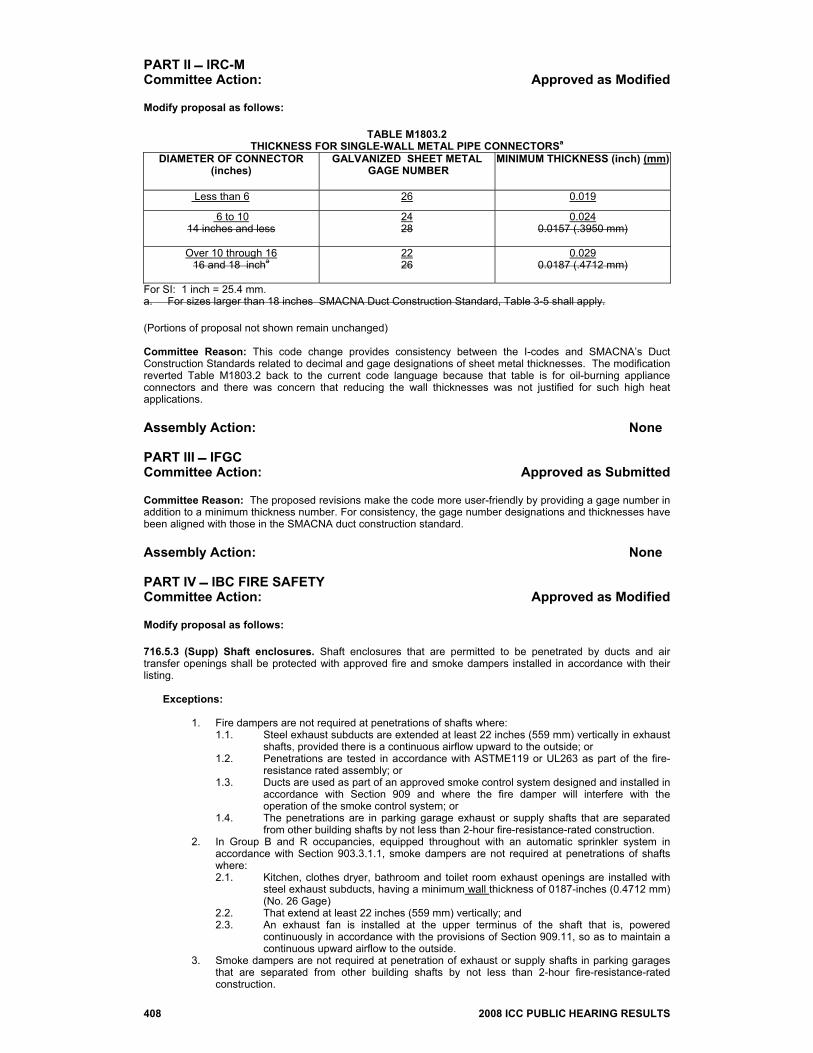
PART II IRC-M Committee Action: Approved as Modified Modify proposal as follows:
TABLE M1803.2 THICKNESS FOR SINGLE-WALL METAL PIPE CONNECTORSa
DIAMETER OF CONNECTOR (inches)
GALVANIZED SHEET METAL GAGE NUMBER
MINIMUM THICKNESS (inch) (mm)
Less than 6 26 0.019
6 to 10 14 inches and less
24 28
0.024 0.0157 (.3950 mm)
Over 10 through 16 16 and 18 incha
22 26
0.029 0.0187 (.4712 mm)
For SI: 1 inch = 25.4 mm. a. For sizes larger than 18 inches SMACNA Duct Construction Standard, Table 3-5 shall apply. (Portions of proposal not shown remain unchanged) Committee Reason: This code change provides consistency between the I-codes and SMACNA’s Duct Construction Standards related to decimal and gage designations of sheet metal thicknesses. The modification reverted Table M1803.2 back to the current code language because that table is for oil-burning appliance connectors and there was concern that reducing the wall thicknesses was not justified for such high heat applications. Assembly Action: None PART III IFGC Committee Action: Approved as Submitted Committee Reason: The proposed revisions make the code more user-friendly by providing a gage number in addition to a minimum thickness number. For consistency, the gage number designations and thicknesses have been aligned with those in the SMACNA duct construction standard. Assembly Action: None PART IV IBC FIRE SAFETY Committee Action: Approved as Modified Modify proposal as follows: 716.5.3 (Supp) Shaft enclosures. Shaft enclosures that are permitted to be penetrated by ducts and air transfer openings shall be protected with approved fire and smoke dampers installed in accordance with their listing.
Exceptions:
1. Fire dampers are not required at penetrations of shafts where: 1.1. Steel exhaust subducts are extended at least 22 inches (559 mm) vertically in exhaust
shafts, provided there is a continuous airflow upward to the outside; or 1.2. Penetrations are tested in accordance with ASTME119 or UL263 as part of the fire-
resistance rated assembly; or 1.3. Ducts are used as part of an approved smoke control system designed and installed in
accordance with Section 909 and where the fire damper will interfere with the operation of the smoke control system; or
1.4. The penetrations are in parking garage exhaust or supply shafts that are separated from other building shafts by not less than 2-hour fire-resistance-rated construction.
2. In Group B and R occupancies, equipped throughout with an automatic sprinkler system in accordance with Section 903.3.1.1, smoke dampers are not required at penetrations of shafts where: 2.1. Kitchen, clothes dryer, bathroom and toilet room exhaust openings are installed with
steel exhaust subducts, having a minimum wall thickness of 0187-inches (0.4712 mm) (No. 26 Gage)
2.2. That extend at least 22 inches (559 mm) vertically; and 2.3. An exhaust fan is installed at the upper terminus of the shaft that is, powered
continuously in accordance with the provisions of Section 909.11, so as to maintain a continuous upward airflow to the outside.
3. Smoke dampers are not required at penetration of exhaust or supply shafts in parking garages that are separated from other building shafts by not less than 2-hour fire-resistance-rated construction.
2008 ICC PUBLIC HEARING RESULTS 409
4. Smoke dampers are not required at penetrations of shafts where ducts are used as part of an approved mechanical smoke control system designed in accordance with Section 909 and where the smoke damper will interfere with the operation of the smoke control system.
5. Fire dampers and combination fire/smoke dampers are not required in kitchen and clothes dryer exhaust system when installed in accordance with the International Mechanical Code.
716.5.4 (Supp) Fire partitions. Ducts and air transfer openings that penetrate fire partitions shall be protected with listed fire dampers installed in accordance with their listing.
Exceptions: In occupancies other than Group H, fire dampers are not required where any of the following apply:
1. The partitions are tenant separation or corridor walls in buildings equipped throughout with an automatic sprinkler system in accordance with Section 903.3.1.1 or 903.3.1.2 and the duct is protected as a through penetration in accordance with Section 712.
2. Tenant partitions in covered mall buildings where the walls are not required by provisions elsewhere in the code to extend to the underside of the floor or roof sheathing, slab or deck above.
3. The duct system is constructed of approved materials in accordance with the International Mechanical Code and the duct penetrating the wall complies with all of the following requirements:
3.1. The duct shall not exceed 100 square inches (0.06 m2). 3.2. The duct shall be constructed of steel a minimum of 0.0217- inch (0.55 mm) in thickness
having a minimum thickness of 0.0157-inches (0.3950 mm) (No. 28 Gage). 3.3. The duct shall not have openings that communicate the corridor with adjacent spaces or
rooms. 3.4. The duct shall be installed above a ceiling. 3.5. The duct shall not terminate at a wall register in the fire-resistance-rated wall. 3.6. A minimum 12-inch-long (305 mm) by 0.060-inch thick (1.52 mm) steel sleeve having a
minimum thickness of 0.0575-inches (1.465 mm) (No. 16 Gage) shall be centered in each duct opening. The sleeve shall be secured to both sides of the wall and all four sides of the sleeve with minimum 11/2-inch by 11/2-inch by 0.060-inch (38 mm by 38 mm by 1.52 mm) steel retaining angles. The retaining angles shall be secured to the sleeve and the wall with No. 10 (M5) screws. The annular space between the steel sleeve and the wall opening shall be filled with mineral wool batting on all sides.
716.6.1(Supp) Through penetrations. In occupancies other than Groups I-2 and I-3, a duct constructed of approved materials in accordance with the International Mechanical Code that penetrates a fire-resistance-rated floor/ceiling assembly that connects not more than two stories is permitted without shaft enclosure protection, provided a listed fire damper is installed at the floor line or the duct is protected in accordance with Section 712.4. For air transfer openings, see Exception 7 to Section 707.2.
Exception: A duct is permitted to penetrate three floors or less without a fire damper at each floor, provided it meets all of the following requirements:
1. The duct shall be contained and located within the cavity of a wall and shall be constructed of
steel having a minimum wall thickness of 0.0187-inches ((0.4712 mm) (No. 26 Gage). 2. The duct shall open into only one dwelling or sleeping unit and the duct system shall be
continuous from the unit to the exterior of the building. 3. The duct shall not exceed 4-inch (102 mm) nominal diameter and the total area of such ducts
shall not exceed 100 square inches (0.065 m2) in any 100 square feet (9.3 m2) of floor area. 4. The annular space around the duct is protected with materials that prevent the passage of flame
and hot gases sufficient to ignite cotton waste where subjected to ASTM E 119 or UL 263 time-temperature conditions under a minimum positive pressure differential of 0.01-inch (2.49 Pa) of water at the location of the penetration for the time period equivalent to the fire-resistance rating of the construction penetrated.
5. Grille openings located in a ceiling of a fire-resistance- rated floor/ceiling or roof/ceiling assembly shall be protected with a listed ceiling radiation damper installed in accordance with Section 716.6.2.1.
Committee Reason: The committee agreed that this revised language was appropriate to bring consistency in language as it relates to decimals and gages stated within the code. Further, the committee agreed that the modification adding the term “wall” in two places to define thickness was an appropriate clarification. Lastly, the committee agreed with the modification to undo the proposed changes for items 3.2 and 3.6 of Section 716.5.4 based on the fact that these thicknesses were based on specific testing results. Assembly Action: None
M17-07/08 PART I IMC Committee Action: Disapproved Committee Reason: There are other items in Section 308, such as masonry chimneys and kitchen exhaust ducts, that have limitations on clearance reduction methods in Table 308.6. To only have a note for solid fuel-burning appliances might cause users to think they can use the table for those other items. Assembly Action: None
410 2008 ICC PUBLIC HEARING RESULTS
PART II IRC-M Committee Action: Approved as Submitted Committee Reason: The added footnote will point users to Section M1306.2.1 to clarify that 12 inches is the absolute minimum clearance to combustibles for solid fuel-burning appliances and that the reduced clearances in the table are not allowed. Assembly Action: None
M18-07/08 Note: The following analysis was not in the Code Change Proposal book but was posted on the ICC website. Analysis: Review of proposed new standard ANSI/ASHRAE/ACCA Standard 183-2007 indicated that, in the opinion of ICC Staff, the standard did comply with ICC standards criteria. Committee Action: Approved as Modified Modify proposal as follows: 312.1 Load calculations. Heating and cooling system design loads for the purpose of sizing systems, appliances and equipment shall be determined in accordance with the procedures described in the ASHRAE/ACCA Standard 183. Heating and cooling loads shall be adjusted to account for load reductions that are achieved when energy recovery systems are utilized in the HVAC system in accordance with the ASHRAE Handbook - HVAC Systems and Equipment. Alternatively, design loads shall be determined by an approved equivalent computation procedure, using the design parameters specified in Chapter 3 of the International Energy Conservation Code. (Portions of proposal not shown remain unchanged) Committee Reason: ASHRAE/ACCA 183 is the ANSI approved standard for commercial peak heating and cooling load calculations and contains all of the necessary information from the ASHRAE Handbook of Fundamentals. It is appropriate to replace the Handbook with this standard because the Handbook is not a standard that meets ICC criteria. The modification deletes the second sentence because the adjustments for load reductions are also included in the new standard. Assembly Action: None
M19-07/08 Committee Action: Disapproved Committee Reason: The proposed testing and balancing requirements are too simplified; there are other methods available. There has been no evidence presented that there are currently problems because of the lack of balancing. Maintenance of the reports by the code official could be a major paperwork problem. Assembly Action: None
M20-07/08 Note: The following analysis was not in the Code Change Proposal book but was posted on the ICC website. Analysis: Review of proposed new standard ANSI/ASHRAE/ACCA Standard 180-2007 indicated that, in the opinion of ICC Staff, the standard did comply with ICC standards criteria. Committee Action: Disapproved Committee Reason: Maintenance of mechanical equipment is the responsibility of the building owner. The code official should not be enforcing this. Section 603 of the International Property Maintenance Code has provisions for maintenance. Assembly Action: None
2008 ICC PUBLIC HEARING RESULTS 411
M21-07/08 Committee Action: Disapproved Committee Reason: There are no drainage provisions to prevent flood damage through the openings and there is no depth of openings prescribed. Assembly Action: None
M22-07/08 Committee Action: Disapproved Committee Reason: The code change needs further work to correct some issues such as the apparent conflict between the 10 foot and 25 foot distances in Section 401.4, Item 3. The term “hazardous locations” in Section 501.2.1.1 should probably be “flood hazard areas”. Assembly Action: None
M23-07/08 Committee Action: Approved as Submitted Committee Reason: This proposal is necessary to correct an inconsistency between Section 403.2.1 and note “g” to Table 403.3. Items # 2 and # 3 prohibit recirculation where the airstream consists of exactly 10% contaminated air, but, note “g” allows recirculation where the airstream consists of exactly 10% contaminated air. Exactly 10 % falls in both the allowed and disallowed categories. Assembly Action: None
M24-07/08 Committee Action: Disapproved Committee Reason: This requirement is probably appropriate for larger mechanical rooms, but this could be misapplied to smaller rooms that would not need ventilation air. Many manufacturers have this requirement in their installation instructions and the installer should follow those instructions. Assembly Action: None
M25-07/08 Committee Action: Disapproved Committee Reason: The current code, under Section 403.2, allows a design engineer to provide less outdoor air when an engineered system is installed. There is no valid reason to completely replace the current language with this proposal. It may not work in all sections of the country. ASHRAE 62.1 has had many years of peer review whereas this proposal has not. Assembly Action: None
M26-07/08 Errata: Add exception to proposal as follows: 404.1 General. Enclosed parking garages shall be provided with mechanical ventilation as prescribed in this chapter. Exception: Private garages classified as Group U occupancies.
412 2008 ICC PUBLIC HEARING RESULTS
Committee Action: Disapproved Committee Reason: Adding this section is unnecessary as the requirement for ventilation of enclosed garages is already included in Table 403.3. Assembly Action: None
M27-07/08 Committee Action: Approved as Submitted Committee Reason: None of the specific systems in Item 4 would cover refrigeration machinery rooms. This code change provides a pointer to the appropriate section for the exhaust discharge termination location. Assembly Action: None
M28-07/08 Committee Action: Disapproved Committee Reason: The proposal provides no details as to when the exhaust systems must run or how they are started or stopped. There are conflicts with other sections of the code such as the exhaust rate for parking garages is 0.75 cfm/ft2 instead of the 1.5 cfm/ft2 in Table 403.3. The term “kitchenettes” is undefined and could be misapplied in the field. Assembly Action: None
M29-07/08 This proposal was heard by the IFC Code Development Committee. Committee Action: Disapproved Committee Reason: The proposal would create conflicts between the ventilation requirements of IMC Chapter 4 and the exhaust requirements of IMC Chapter 5. The proposal also mentions nickel metal hydride batteries in Section 407.2, a type of battery that was rejected by disapproval of code change F97-07/08. The scope of IMC Chapter 4 is to occupied spaces, which does not include battery rooms or cabinets. Therefore, moving the provisions to that chapter would be inappropriate. Assembly Action: None
M30-07/08 PART I IMC Committee Action: Approved as Modified Modify proposal as follows: 504.6.4 Duct length. The maximum allowable exhaust duct length shall be determined by one of the methods specified in Sections 504.6.4.1 through 504.6.4.3 2. 504.6.4.3 Booster fan. The maximum length of the exhaust duct shall be determined by the booster fan manufacturer’s installation instructions. Booster fans shall be listed and labeled for use in dryer exhaust duct systems. The booster fan shall be installed in accordance with the manufacturer’s installation instructions. (Portions of proposal not shown remain unchanged) Committee Reason: This is a needed reorganization that breaks out specific requirements, such as transition ducts and maximum duct length, and adds a new table for duct fitting equivalent length. The modification deletes the booster fan section because the supporting standard is not yet approved.
2008 ICC PUBLIC HEARING RESULTS 413
Assembly Action: None PART II IRC-M Committee Action: Disapproved Committee Reason: The standard for dryer exhaust duct ventilators in proposed Section M1502.3.4.3 is not yet approved. There was no technical justification for reducing the maximum duct length from 35 feet to 25 feet. Assembly Action: None
M31-07/08 Committee Action: Disapproved Committee Reason: There are many clothes dryers still on the market that are not designed for more than 25 feet of exhaust duct length, including stackable washer/dryer combinations that are prevalent in condominiums. The existing exception already allows for the longer duct lengths when allowed by the manufacturer’s instructions. Assembly Action: None
M32-07/08 PART I IMC Withdrawn By Proponent PART II IRC-M Committee Action: Approved as Submitted Committee Reason: This proposal makes the determination of equivalent lengths of fittings easier for the user by replacing the text for standard elbows and the exception for large radius elbows with a new table. Assembly Action: None
M33-07/08 PART I IMC Committee Action: Disapproved Committee Reason: This proposal goes beyond the protection requirements already in the code in Section 305.5 and would require protection in areas that do not normally require it. The proposal could add to construction costs beyond the value added by the plates. Assembly Action: None PART II IRC-M Committee Action: Disapproved Committee Reason: Protection from fasteners penetrating walls is already covered in Section M1308.2. This proposal provided no prescriptive requirements to provide any guidance to the user such as maximum fastener lengths. Assembly Action: None
M34-07/08 Committee Action: Approved as Modified Modify proposal as follows: 504.8 (IFGC [M]614.8) Common exhaust systems for clothes dryers located in multi-story structures. Where a common multi-story duct system is designed and installed to convey exhaust from multiple clothes dryers, the construction of such system shall be in accordance with all of the following:
414 2008 ICC PUBLIC HEARING RESULTS
1. The shaft in which the duct is installed shall be constructed and fire resistant rated as required by the International Building Code.
2. Dampers shall be prohibited in the exhaust duct. Penetrations of the shaft and ductwork shall be protected in accordance with Section 607.5.5, Exception 2.
3. Rigid metal ductwork shall be installed within the shaft to convey the exhaust. The ductwork shall be constructed of not less than 24 gage sheet steel having a minimum thickness of (0.0187-inches) (0.471 mm) (No.26 gage) and in accordance with SMACNA Duct Construction Standards.
4. The ductwork within the shaft shall be designed and installed without offsets. 5. The exhaust fan motor design shall be in accordance with Section 503.2. 6. The exhaust fan motor shall be located outside of the airstream. 7. The exhaust fan shall run continuously, and shall be connected to a standby power source. 8. The exhaust fan operation shall be monitored in an approved location and shall initiate an audible or
visual signal when the fan is not in operation. 9. Makeup air shall be provided for the exhaust system.
10. A cleanout opening shall be located at the base of the shaft to provide access to the duct to allow for cleaning and inspection. The finished opening shall be not less than 12 inches by 12 inches. 11. Screens shall not be installed at the termination. Committee Reason: Common exhaust ducts for clothes dryers in multi-story buildings are frequently used and this code change adds some prescriptive requirements to allow the code official to ensure proper installation. The modification changes the gage of the duct material from 24 to 26 for consistency with the IBC fire safety requirements. Assembly Action: None
M35-07/08 Committee Action: Disapproved Committee Reason: The action was based on the proponent’s request for disapproval to allow possible revisions in a public comment and in favor of M39-07/08. Assembly Action: None
M36-07/08 Committee Action: Approved as Submitted Committee Reason: This code change adds another welding method for forming duct joints. This method is currently widely used in the industry and it is easier to fabricate and make liquid tight. Assembly Action: None
M37-07/08 Committee Action: Approved as Modified Modify proposal as follows: 506.3.2.5 (Supp) Grease duct test. Prior to the use or concealment of any portion of a grease duct system, a leakage test shall be performed in the presence of the code official. Ducts shall be considered to be concealed where installed in shafts or covered by coatings or wraps that prevent the duct work from being visually inspected on all sides. The permit holder shall be responsible to provide the necessary equipment and perform the grease duct leakage test. A light test shall be performed to determine that all welded and brazed joints are liquid tight. A light test shall be performed by passing a lamp having a power rating of not less than 100 watts through the entire section of duct work to be tested. The lamp shall be open so as to emit light equally in all directions perpendicular to the duct walls. A test shall be performed for the entire duct system, including the hood-to-duct connection. The duct work shall be permitted to be tested in sections, provided that every joint is tested. For listed factory-built grease ducts, this test shall be limited to duct joints assembled in the field and shall exclude factory welds. Exception: Subject to the approval of the code official, the leakage test need not be performed in the presence of the code official provided that an approved agency submits a report of the results of the test. Committee Reason: The deleted text was being used in the field to require various test methods other than the light test that the contractor was expecting. This change will provide uniform inspection practice. The modification allows factory-made welds to be exempted from the field tests. Assembly Action: None
2008 ICC PUBLIC HEARING RESULTS 415
M38-07/08 Committee Action: Approved as Submitted Committee Reason: The exception is unnecessary language that is adequately addressed in other sections of the code such as Sections 104.4 and 107.1.1. Assembly Action: None
M39-07/08 Committee Action: Approved as Modified Modify proposal as follows: 506.3.6.9 (Supp) Grease duct clearances. Grease duct systems and exhaust equipment serving a Type I hood shall have a clearance to combustible construction of not less than 18 inches (457 mm), and shall have a clearance to noncombustible construction and gypsum wallboard attached to noncombustible structures of not less than 3 inches (76 mm). Exception: Factory-built commercial kitchen grease ducts listed and labeled in accordance with UL 1978 and listed and labeled exhaust equipment installed in accordance with Section 304.1. 506.3.10 Grease Duct Enclosures. A grease duct serving a Type I hood that penetrates a ceiling, wall or floor shall be enclosed from the point of penetration to the outlet terminal. A duct shall penetrate exterior walls only at locations where unprotected openings are permitted by the International Building Code. The duct enclosure shall serve a single grease duct and shall not contain other ducts, piping or wiring systems. Duct enclosures shall be sealed around the duct at the point of penetration and vented to the outside of the building through the use of weather-protected openings. Duct enclosures shall be either field-applied or prefabricated. Duct enclosures shall be as prescribed by Sections 506.3.10.1, 506.3.10.2 or 506.3.10.3. Exception: A duct enclosure shall not be required for a grease duct that penetrates only a non fire- resistance-rated roof/ceiling assembly. 506.3.10.1 Shaft enclosure. Commercial kitchen grease ducts constructed in accordance with Section 506.3.1 shall be permitted to be enclosed in accordance with the International Building Code requirements for shaft construction. Such grease duct systems and exhaust equipment shall have a clearance to combustible construction of not less than 18 inches (457 mm), and shall have a clearance to noncombustible construction and gypsum wallboard attached to noncombustible structures of not less than 6 inches (76 mm). 506.3.10.2 Field applied grease duct enclosure. Field-applied grease duct enclosure assemblies shall consist of Commercial kitchen grease ducts constructed in accordance with Section 506.3.1 shall be enclosed by a field-applied grease duct enclosure that is a listed and labeled material, system, product, or method of construction specifically evaluated for such purpose in accordance with ASTM E2336. The surface of the duct shall be continuously covered on all sides from the point at which the duct originates to the outlet terminal. Duct penetrations shall be protected with a through-penetration firestop system classified in accordance with ASTM E 814 or UL 1479 and having an “F” and “T” rating equal to the fire-resistance rating of the assembly being penetrated. Such systems shall be installed in accordance with the listing and the manufacturer’s installation instructions. Exposed duct wrap systems shall be protected where subject to physical damage. 506.3.10.3 Prefabricated grease duct enclosure assemblies. Prefabricated grease duct enclosure assemblies shall consist of listed commercial kitchen grease ducts constructed in accordance with Section 506.3.1. Such grease ducts shall be enclosed within a prefabricated grease duct enclosure assembly that is listed and labeled and specifically evaluated for such purpose in accordance with UL 2221. Duct penetrations shall be protected with a through-penetration firestop system classified in accordance with ASTM E 814 or UL 1479 and having an “F” and “T” rating equal to the fire-resistance rating of the assembly being penetrated. Such systems shall be installed in accordance with the listing and the manufacturer’s installation instructions. 506.3.10.4 Duct enclosure not required. A duct enclosure shall not be required for a grease duct that penetrates only a non fire-resistance-rated roof/ceiling assembly. Committee Reason: This proposal appropriately reorganizes Section 506.3.10 to consolidate and clarify the various methods of enclosing grease ducts. Section 506.3.10 will now direct the user to one of three methods in the subsequent sections which each provide technical guidance for the particular method. The modification reverts Section 506.3.9 back to 506.3.6, adds back some language in Section 506.3.10 that was in the existing code language and inadvertently omitted, deletes the exception to Section 506.3.10 and moves it to a new Section 506.3.10.4, deletes redundant language in the first line of Section 506.3.10.2 and adds “shall be” for grammatical correctness and adds “or UL 1479” to follow ASTM E 814 which was in existing code language. Assembly Action: Disapproved
416 2008 ICC PUBLIC HEARING RESULTS
M40-07/08 Committee Action: Approved as Submitted Committee Reason: This proposal breaks the existing exception into two exceptions and adds a third exception to clarify that field-applied grease duct enclosure systems allowed by Section 506.3.10 can be installed with the clearances allowed by their listing. Assembly Action: None
M41-07/08 Committee Action: Approved as Submitted Committee Reason: The standard width for openings throughout the code is 22 inches which is based on average shoulder width. The opening width in this section should be the same. Assembly Action: None
M42-07/08 Committee Action: Approved as Submitted Committee Reason: This code change adds cleanout location requirements for in-line fans that are consistent with those in NFPA 96 and are necessary for the safety of maintenance personnel and inspectors. Assembly Action: None
M43-07/08 Committee Action: Approved as Submitted Committee Reason: Changing the location of the exhaust outlet to 3 feet will make the code consistent with NFPA 96 and other IMC, IFGC and IRC code sections. The last sentence was deleted because it is redundant with Section 506.5.2. Assembly Action: None
M44-07/08 Committee Action: Approved as Modified Modify proposal as follows: 506.4.2 (Supp) Type II terminations. Exhaust outlets serving Type II hoods shall terminate in accordance with the hood manufacturer’s installation instructions and shall comply with all of the following:
1. Exhaust outlets shall terminate not less than 3 feet (914 mm) in any direction from openings into the building.
2. Outlets shall terminate not less than 10 feet (3048 mm) from property lines or buildings on the same lot. 3. Outlets shall terminate not less than10 feet (3048 mm) above grade. 4. Outlets shall terminate not less than 30 inches (762 mm) above the roof surface. 5. Outlets shall terminate not less than 30 inches f(762 mm) from exterior vertical walls. 6. Outlets shall be protected against local weather conditions. 7. Outlets shall not be directed onto walkways. 8. Outlets shall not create a nuisance.
9 8. Outlets shall meet the provisions for exterior wall opening protectives in accordance with the International Building Code. Committee Reason: Section 506.4.1 was deleted and the termination requirements that it referenced in Section 401.4 are added to the list of exhaust outlet termination requirements in Section 506.4.3 in order to have all requirements in one location. The modification deleted the 8th item because the term “nuisance” is too subjective. Assembly Action: None
2008 ICC PUBLIC HEARING RESULTS 417
M45-07/08 Committee Action: Approved as Submitted Committee Reason: Sidewall exhaust outlets are commonly used in multi-story buildings. The language in current Item 4 could be interpreted to not allow such sidewall outlets. Assembly Action: None
M46-07/08 Committee Action: Approved as Submitted Committee Reason: Because recirculating systems do not exhaust heat and moisture from the kitchen, ventilation in accordance with Table 403.3 in needed to remove the heat and moisture. Assembly Action: None
M47-07/08 Committee Action: Approved as Submitted Committee Reason: This code change clarifies that it is acceptable to reduce fan speeds during no-load conditions, but, if cooking appliances are operating in standby mode, the fans cannot be completely shut off. Assembly Action: None
M48-07/08 Committee Action: Disapproved Committee Reason: The committee preferred the language in M47-07/08. Assembly Action: None
M49-07/08 Committee Action: Approved as Submitted Committee Reason: The term ”part-load” is more appropriate because “no-load” seems to indicate there is not any operation of the cooking equipment at all. Assembly Action: None
M50-07/08 Committee Action: Approved as Submitted Committee Reason: This code change clarifies which appliances require Type I or Type II hoods. Previously, the user could only infer from Section 507.13 that medium-duty, heavy-duty and extra-heavy-duty cooking appliances required Type I hoods and light-duty appliances required Type II hoods. Assembly Action: None
418 2008 ICC PUBLIC HEARING RESULTS
M51-07/08 Committee Action: Disapproved Committee Reason: This code change would incorrectly reverse the intent of this section by requiring deactivation of the cooking appliance rather than activation of the exhaust hood. The new definition of Interlock in M4-07/08 correctly addresses this issue. Assembly Action: None
M52-07/08 Committee Action: Approved as Submitted Committee Reason: Replacing the lists of appliances that do not require Type II hoods with this new language will allow more appliances to operate without hoods. Lists are never all-inclusive and this will allow new appliances that come on the market in the future to be operated without hoods. Assembly Action: None
M53-07/08 Committee Action: Disapproved Committee Reason: Disapproval was based on the action taken on M52-07/08. Assembly Action: None
M54-07/08 Committee Action: Disapproved Committee Reason: Disapproval was based on the action taken on M52-07/08. The committee did not want to start adding to a list of exceptions. The Energy Star specifications are based on water consumption and idle energy rather than the heat load addressed in this section. Assembly Action: None
M55-07/08 Withdrawn By Proponent
M56-07/08 Committee Action: Disapproved Committee Reason: The proposed language would cause confusion with the second exception to Section 507.1. The proponent’s reason seems to require testing to only EPA 202 which would ignore many of the requirements of UL 710B which is required in Section 507.1. Assembly Action: None
M57-07/08 Withdrawn By Proponent
2008 ICC PUBLIC HEARING RESULTS 419
M58-07/08 Committee Action: Approved as Submitted Committee Reason: The current language would not allow two solid fuel-burning appliances to be served by one Type I hood. The code change clarifies the intent is to prevent heavy-duty, medium-duty and light-duty cooking appliances from being under the same hood as an extra-heavy-duty cooking appliance. Assembly Action: None
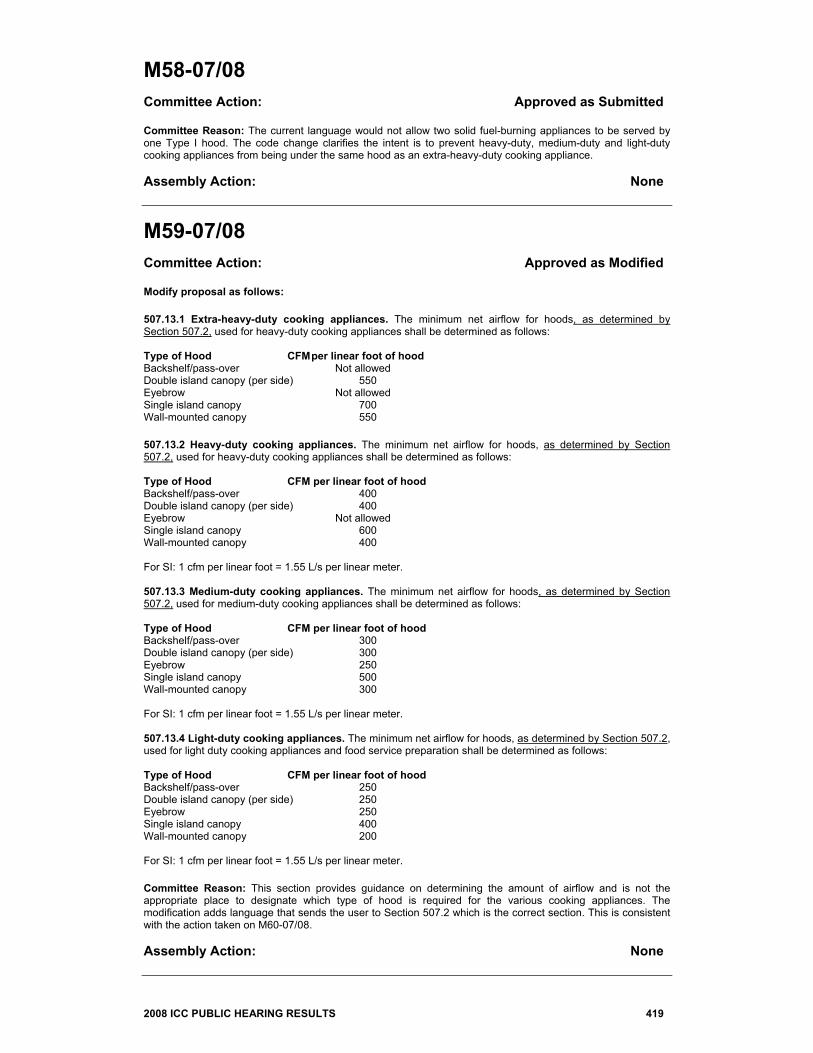
M59-07/08 Committee Action: Approved as Modified Modify proposal as follows: 507.13.1 Extra-heavy-duty cooking appliances. The minimum net airflow for hoods, as determined by Section 507.2, used for heavy-duty cooking appliances shall be determined as follows: Type of Hood CFM per linear foot of hood Backshelf/pass-over Not allowed Double island canopy (per side) 550 Eyebrow Not allowed Single island canopy 700 Wall-mounted canopy 550 507.13.2 Heavy-duty cooking appliances. The minimum net airflow for hoods, as determined by Section 507.2, used for heavy-duty cooking appliances shall be determined as follows: Type of Hood CFM per linear foot of hood Backshelf/pass-over 400 Double island canopy (per side) 400 Eyebrow Not allowed Single island canopy 600 Wall-mounted canopy 400 For SI: 1 cfm per linear foot = 1.55 L/s per linear meter. 507.13.3 Medium-duty cooking appliances. The minimum net airflow for hoods, as determined by Section 507.2, used for medium-duty cooking appliances shall be determined as follows: Type of Hood CFM per linear foot of hood Backshelf/pass-over 300 Double island canopy (per side) 300 Eyebrow 250 Single island canopy 500 Wall-mounted canopy 300 For SI: 1 cfm per linear foot = 1.55 L/s per linear meter. 507.13.4 Light-duty cooking appliances. The minimum net airflow for hoods, as determined by Section 507.2, used for light duty cooking appliances and food service preparation shall be determined as follows: Type of Hood CFM per linear foot of hood Backshelf/pass-over 250 Double island canopy (per side) 250 Eyebrow 250 Single island canopy 400 Wall-mounted canopy 200 For SI: 1 cfm per linear foot = 1.55 L/s per linear meter. Committee Reason: This section provides guidance on determining the amount of airflow and is not the appropriate place to designate which type of hood is required for the various cooking appliances. The modification adds language that sends the user to Section 507.2 which is the correct section. This is consistent with the action taken on M60-07/08. Assembly Action: None
420 2008 ICC PUBLIC HEARING RESULTS
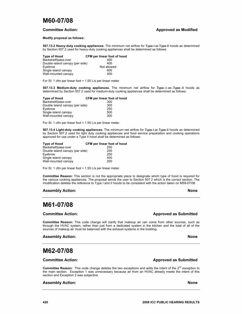
M60-07/08 Committee Action: Approved as Modified Modify proposal as follows: 507.13.2 Heavy-duty cooking appliances. The minimum net airflow for Type I or Type II hoods as determined by Section 507.2 used for heavy-duty cooking appliances shall be determined as follows: Type of Hood CFM per linear foot of hood Backshelf/pass-over 400 Double island canopy (per side) 400 Eyebrow Not allowed Single island canopy 600 Wall-mounted canopy 400 For SI: 1 cfm per linear foot = 1.55 L/s per linear meter. 507.13.3 Medium-duty cooking appliances. The minimum net airflow for Type I or Type II hoods as determined by Section 507.2 used for medium-duty cooking appliances shall be determined as follows: Type of Hood CFM per linear foot of hood Backshelf/pass-over 300 Double island canopy (per side) 300 Eyebrow 250 Single island canopy 500 Wall-mounted canopy 300 For SI: 1 cfm per linear foot = 1.55 L/s per linear meter. 507.13.4 Light-duty cooking appliances. The minimum net airflow for Type I or Type II hoods as determined by Section 507.2 used for light duty cooking appliances and food service preparation and cooking operations approved for use under a Type II hood shall be determined as follows: Type of Hood CFM per linear foot of hood Backshelf/pass-over 250 Double island canopy (per side) 250 Eyebrow 250 Single island canopy 400 Wall-mounted canopy 200 For SI: 1 cfm per linear foot = 1.55 L/s per linear meter. Committee Reason: This section is not the appropriate place to designate which type of hood is required for the various cooking appliances. The proposal sends the user to Section 507.2 which is the correct section. The modification deletes the reference to Type I and II hoods to be consistent with the action taken on M59-07/08. Assembly Action: None
M61-07/08 Committee Action: Approved as Submitted Committee Reason: This code change will clarify that makeup air can come from other sources, such as through the HVAC system, rather than just from a dedicated system in the kitchen and the total of all of the sources of makeup air must be balanced with the exhaust systems in the building. Assembly Action: None
M62-07/08 Committee Action: Approved as Submitted Committee Reason: This code change deletes the two exceptions and adds the intent of the 2nd exception to the main section. Exception 1 was unnecessary because air from an HVAC already meets the intent of this section and Exception 2 was subjective. Assembly Action: None
2008 ICC PUBLIC HEARING RESULTS 421
M63-07/08 Committee Action: Disapproved Committee Reason: Many times it is necessary to heat the dining area and cool the kitchen at the same time. If makeup air is transferred from the dining area to the kitchen, this could be misconstrued to mean that the makeup air is being heated and cooled simultaneously. This language should be limited to dedicated makeup air systems. Assembly Action: None
M64-07/08 Committee Action: Approved as Submitted Committee Reason: No dampers should be allowed in hazardous exhaust systems. Stopping the flow of such exhausts would pose safety risks for building occupants and emergency responders. Assembly Action: None
M65-07/08 Committee Action: Disapproved Committee Reason: The committee did not believe the standard, which is specific to grease ducts, was appropriate for hazardous exhausts. The proponent’s reason discussed tests conducted at 500° F for short durations, but this section is for systems with normal operating temperatures in excess of 600° F. Assembly Action: None
M66-07/08 Committee Action: Disapproved Committee Reason: There was no technical justification for removing clothes dryers from the list of prohibited appliances. There was no evidence presented to the committee that there are ERV systems that will work with grease duct exhaust systems. Assembly Action: None
M67-07/08 Committee Action: Approved as Submitted Committee Reason: Because Section 403.2.1 allows some air to be recirculated from spaces such as locker rooms, it makes no sense to prohibit the same exhaust system from being in return air plenums over such spaces. This proposal will allow the designer more flexibility in designing exhaust systems. Assembly Action: None
M68-07/08 Committee Action: Disapproved Committee Reason: This proposal would allow combustibles to be in plenums in R-2 occupancies, many of which are built of noncombustible construction. There was no compelling reason to reduce the requirements to allow combustibles in plenums in such construction. Assembly Action: None
422 2008 ICC PUBLIC HEARING RESULTS
M69-07/08 Committee Action: Disapproved Committee Reason: Disapproval was based on the action taken on M68-07/08. Assembly Action: None
M70-07/08 Committee Action: Disapproved Committee Reason: The proposed language is subjective and could lead to uneven enforcement by different jurisdictions. Assembly Action: None
M71-07/08 Committee Action: Approved as Submitted Committee Reason: The heat release and optical density requirements are contained in UL 2043 which is already specified in this section. This code change breaks the existing section into separate sections for clarity. Assembly Action: None
M72-07/08 Committee Action: Disapproved Committee Reason: The UL 2043 standard has been revised to cover not only electrical equipment but also discrete plumbing and mechanical equipment. However, the committee had not seen the revised standard and did not know what might be covered. The word “discrete” was considered to be subjective and could lead to uneven enforcement in the field. Assembly Action: None
M73-07/08 Committee Action: Approved as Modified Modify proposal as follows: 602.2.1.6 Plastic piping. Materials used for plastic piping exposed within a plenum shall be used only in wet pipe systems for the purpose of transporting liquids and shall have a flame spread index of not more than 25 and a smoke-developed index of not more than 50 when tested in accordance with ASTM E 84 or UL 723. Piping shall be listed and labeled for plenum use. The listing shall state that the pipe be based on an ASTM E 84 or UL 723 test specimen that did not contain water during the fire test. (Renumber subsequent sections) Committee Reason: It has become a common practice for manufacturers to test plastic pipe to ASTM E 84 with the pipe full of water. This is not the intent of the code and this code change clarifies the intent. The modification further clarifies that this is a material test and the plastic piping is not necessarily “wet pipe” but may only be used to transport liquids, such as waste drainage piping. The modification also adds the equivalent UL 723 Standard in addition to the ASTM E 84 Standard. Assembly Action: None
2008 ICC PUBLIC HEARING RESULTS 423
M74-07/08 Committee Action: Disapproved Committee Reason: The proposal is too vague as to when or where the through-penetration fire stop system can be used. There was some dispute among proponents and opponents as to which standards apply. There is no standard similar to the grease duct standard for the designer and code official to rely on. Assembly Action: None
M75-07/08 Committee Action: Approved as Modified Modify proposal as follows: 603.7 Rigid duct penetrations. Duct system penetrations of walls, floors, ceilings and roofs and air transfer openings in such building components shall be protected as required by Section 607. Ducts in a private garage and ducts penetrating the walls or ceilings separating a dwelling from a private garage shall be continuous and constructed of a minimum 26 gage (0.48 mm) galvanized sheet metal and shall have no openings into the garage. Fire and smoke dampers are not required in such ducts passing through the wall or ceiling separating a dwelling from a private garage except where required by Chapter 7 of the International Building Code. Except where required by Chapter 7 of the International Building Code, fire and smoke dampers shall not be required in ducts passing through the walls or ceilings separating private garages from dwellings where all of the following conditions are met: 1. The ducts are continuous. 2. The ducts are constructed of a minimum of 26 gage (0.0187 inches) (0.048 mm) galvanized sheet metal. 3. The ducts do not have openings into the garage. Committee Reason: The purpose of this code change is to clarify that ducts penetrating a wall or ceiling separating a garage from a dwelling unit are not required to have fire or smoke dampers if the ducts meet certain construction requirements. The modification further clarifies the requirements by breaking the new language into listed items. Assembly Action: None
M76-07/08 Committee Action: Disapproved Committee Reason: There was some confusion about whether these fittings would be in conflict with Section 603.8.3 which allows plastic fittings only underground. UL 2043 has been revised to cover not only electrical equipment but also discrete plumbing and mechanical equipment. However, the committee had not seen the revised standard and did not know what might be covered. Assembly Action: None
M77-07/08 Committee Action: Disapproved Committee Reason: There was some confusion about whether these fittings would be in conflict with Section 603.8.3 which allows plastic fittings only underground. There were questions about which portions of UL 181 would apply to this product. Assembly Action: None
424 2008 ICC PUBLIC HEARING RESULTS
M78-07/08 Committee Action: Disapproved Committee Reason: The application of UL 181 to this section is inappropriate. UL 181 is not intended to apply to underground ducts. Assembly Action: None
M79-07/08 PART I IMC Committee Action: Approved as Submitted Committee Reason: This code change adds needed guidance for sealing metal ductwork and changes the term “tapes and mastics” to the more appropriate “closure systems”. Assembly Action: None PART II IRC-M Committee Action: Approved as Submitted Committee Reason: This code change adds needed guidance for sealing metal ductwork. The committee wanted this section to be consistent with the IMC. Assembly Action: None
M80-07/08 PART I IMC Committee Action: Approved as Submitted Committee Reason: The exception allows continuously welded and locking type joints to be exempt from sealing. This agrees with the SMACNA standard. Assembly Action: None PART II IRC-M Committee Action: Approved as Submitted Committee Reason: The exception allows continuously welded and locking type joints to be exempt from sealing. This is already allowed in DOE’s RESCHECK software for energy conservation. Assembly Action: None
M81-07/08 Committee Action: Disapproved Committee Reason: Air dispersion systems are useful products that need to be recognized in the code. Not all listed items in the code have standards that meet ICC criteria for standards. Assembly Action: None
M82-07/08 Committee Action: Disapproved Committee Reason: The committee considered this proposal to be incomplete because it only addresses the commercial requirements of the IECC and does not address the residential requirements which would also apply to some IMC applications. There was concern that copying the IECC requirements into the IMC could cause problems if one committee revised this section and the other did not. Assembly Action: None
2008 ICC PUBLIC HEARING RESULTS 425
M83-07/08 Committee Action: Disapproved Committee Reason: The action was based on the proponent’s request for disapproval to allow for possible revisions in a public comment. Assembly Action: None
M84-07/08 Committee Action: Approved as Submitted Committee Reason: Shaft enclosures that do not extend to the bottom of the building need to be protected at the bottom. This is covered in the IBC and needs to be in the IMC as well. Assembly Action: None
M85-07/08 Committee Action: Disapproved Committee Reason: All of the technical requirements of Chapter 7 have been deleted from this code with a reference to NFPA 31 which adequately addresses the issue of this code change. Assembly Action: None
M86-07/08 Committee Action: Disapproved Committee Reason: The action was based on the proponent’s request for disapproval. Assembly Action: None
M87-07/08 Committee Action: Approved as Submitted Committee Reason: This code change reorganizes the section to apply the correct standards to the various appliances. Assembly Action: None
M88-07/08 PART I IMC Committee Action: Disapproved Committee Reason: The committee thought that the last sentence in the proposed modification was confusing and needed to be deleted. Without the modification that added the term “unconditioned” to attics and crawl spaces, the proposed language is incomplete because it is appropriate to take return air from conditioned attics and crawl spaces. Assembly Action: None
426 2008 ICC PUBLIC HEARING RESULTS
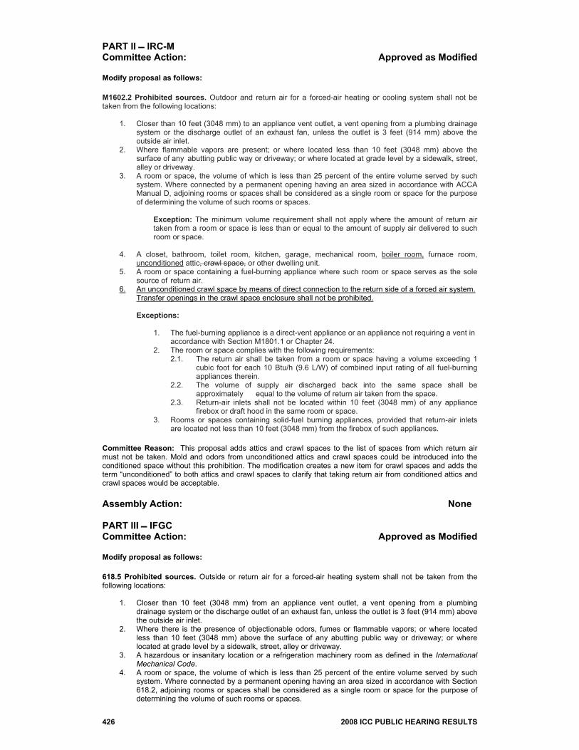
PART II IRC-M Committee Action: Approved as Modified Modify proposal as follows: M1602.2 Prohibited sources. Outdoor and return air for a forced-air heating or cooling system shall not be taken from the following locations:
1. Closer than 10 feet (3048 mm) to an appliance vent outlet, a vent opening from a plumbing drainage system or the discharge outlet of an exhaust fan, unless the outlet is 3 feet (914 mm) above the outside air inlet.
2. Where flammable vapors are present; or where located less than 10 feet (3048 mm) above the surface of any abutting public way or driveway; or where located at grade level by a sidewalk, street, alley or driveway.
3. A room or space, the volume of which is less than 25 percent of the entire volume served by such system. Where connected by a permanent opening having an area sized in accordance with ACCA Manual D, adjoining rooms or spaces shall be considered as a single room or space for the purpose of determining the volume of such rooms or spaces.
Exception: The minimum volume requirement shall not apply where the amount of return air
taken from a room or space is less than or equal to the amount of supply air delivered to such room or space.
4. A closet, bathroom, toilet room, kitchen, garage, mechanical room, boiler room, furnace room,
unconditioned attic, crawl space, or other dwelling unit. 5. A room or space containing a fuel-burning appliance where such room or space serves as the sole
source of return air. 6. An unconditioned crawl space by means of direct connection to the return side of a forced air system. Transfer openings in the crawl space enclosure shall not be prohibited. Exceptions: 1. The fuel-burning appliance is a direct-vent appliance or an appliance not requiring a vent in accordance with Section M1801.1 or Chapter 24. 2. The room or space complies with the following requirements:
2.1. The return air shall be taken from a room or space having a volume exceeding 1 cubic foot for each 10 Btu/h (9.6 L/W) of combined input rating of all fuel-burning appliances therein.
2.2. The volume of supply air discharged back into the same space shall be approximately equal to the volume of return air taken from the space.
2.3. Return-air inlets shall not be located within 10 feet (3048 mm) of any appliance firebox or draft hood in the same room or space.
3. Rooms or spaces containing solid-fuel burning appliances, provided that return-air inlets are located not less than 10 feet (3048 mm) from the firebox of such appliances.
Committee Reason: This proposal adds attics and crawl spaces to the list of spaces from which return air must not be taken. Mold and odors from unconditioned attics and crawl spaces could be introduced into the conditioned space without this prohibition. The modification creates a new item for crawl spaces and adds the term “unconditioned” to both attics and crawl spaces to clarify that taking return air from conditioned attics and crawl spaces would be acceptable. Assembly Action: None PART III IFGC Committee Action: Approved as Modified Modify proposal as follows: 618.5 Prohibited sources. Outside or return air for a forced-air heating system shall not be taken from the following locations:
1. Closer than 10 feet (3048 mm) from an appliance vent outlet, a vent opening from a plumbing drainage system or the discharge outlet of an exhaust fan, unless the outlet is 3 feet (914 mm) above the outside air inlet.
2. Where there is the presence of objectionable odors, fumes or flammable vapors; or where located less than 10 feet (3048 mm) above the surface of any abutting public way or driveway; or where located at grade level by a sidewalk, street, alley or driveway.
3. A hazardous or insanitary location or a refrigeration machinery room as defined in the International Mechanical Code.
4. A room or space, the volume of which is less than 25 percent of the entire volume served by such system. Where connected by a permanent opening having an area sized in accordance with Section 618.2, adjoining rooms or spaces shall be considered as a single room or space for the purpose of determining the volume of such rooms or spaces.
2008 ICC PUBLIC HEARING RESULTS 427
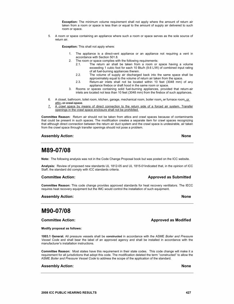
Exception: The minimum volume requirement shall not apply where the amount of return air taken from a room or space is less than or equal to the amount of supply air delivered to such room or space.
5. A room or space containing an appliance where such a room or space serves as the sole source of
return air. Exception: This shall not apply where:
1. The appliance is a direct-vent appliance or an appliance not requiring a vent in accordance with Section 501.8.
2. The room or space complies with the following requirements: 2.1. The return air shall be taken from a room or space having a volume
exceeding 1 cubic foot for each 10 Btu/h (9.6 L/W) of combined input rating of all fuel-burning appliances therein.
2.2. The volume of supply air discharged back into the same space shall be approximately equal to the volume of return air taken from the space.
2.3. Return-air inlets shall not be located within 10 feet (3048 mm) of any appliance firebox or draft hood in the same room or space.
3. Rooms or spaces containing solid fuel-burning appliances, provided that return-air inlets are located not less than 10 feet (3048 mm) from the firebox of such appliances.
6. A closet, bathroom, toilet room, kitchen, garage, mechanical room, boiler room, or furnace room, or attic, or crawl space.
7. A crawl space by means of direct connection to the return side of a forced air system. Transfer openings in the crawl space enclosure shall not be prohibited.
Committee Reason: Return air should not be taken from attics and crawl spaces because of contaminants that could be present in such spaces. The modification creates a separate item for crawl spaces recognizing that although direct connection between the return air duct system and the crawl space is undesirable, air taken from the crawl space through transfer openings should not pose a problem. Assembly Action: None
M89-07/08 Note: The following analysis was not in the Code Change Proposal book but was posted on the ICC website. Analysis: Review of proposed new standards UL 1812-05 and UL 1815-01indicated that, in the opinion of ICC Staff, the standard did comply with ICC standards criteria. Committee Action: Approved as Submitted Committee Reason: This code change provides approved standards for heat recovery ventilators. The IECC requires heat recovery equipment but the IMC would control the installation of such equipment. Assembly Action: None
M90-07/08 Committee Action: Approved as Modified Modify proposal as follows: 1003.1 General. All pressure vessels shall be constructed in accordance with the ASME Boiler and Pressure Vessel Code and shall bear the label of an approved agency and shall be installed in accordance with the manufacturer’s installation instructions. Committee Reason: Most states have this requirement in their state codes. This code change will make it a requirement for all jurisdictions that adopt this code. The modification deleted the term ”constructed” to allow the ASME Boiler and Pressure Vessel Code to address the scope of the application of the standard. Assembly Action: None
428 2008 ICC PUBLIC HEARING RESULTS
M91-07/08 PART I IMC Committee Action: Disapproved Committee Reason: This is not an enforcement issue for the mechanical inspector. This should be addressed at the manufacturer’s level rather than in the code. There are other ways to address this issue. Assembly Action: Approved as Submitted PART II IRC-M Committee Action: Disapproved Committee Reason: The installation of locking access port caps would be better addressed with the HVAC manufacturers rather than in the code. Having them installed during the manufacturing process would insure wider usage and would probably have less cost impact to the homeowner. Assembly Action: None
M92-07/08 PART I IMC Committee Action: Disapproved Committee Reason: The installation of locking caps for existing buildings would be better located in the IPMC rather than the IMC. Assembly Action: None PART II IRC-M Committee Action: Disapproved Committee Reason: Based on the action taken on M91-07/08, Part II. Installing the locking access port caps retroactively is more of a maintenance issue. Assembly Action: None
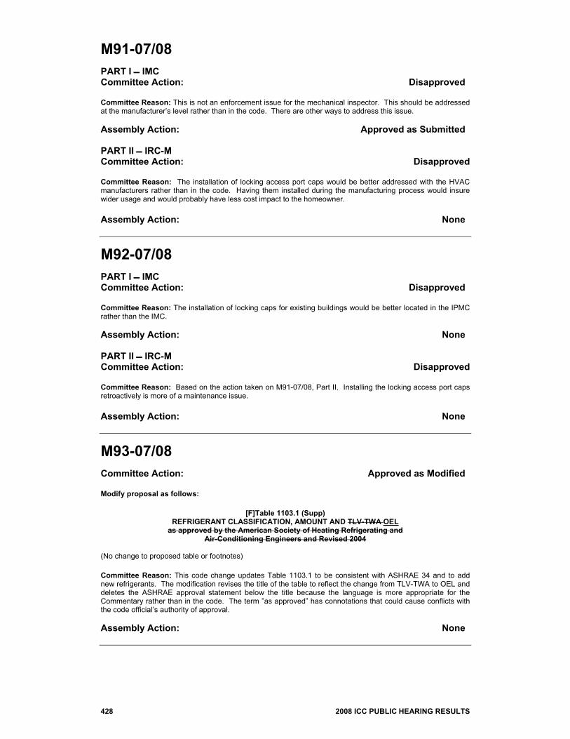
M93-07/08 Committee Action: Approved as Modified Modify proposal as follows:
[F]Table 1103.1 (Supp) REFRIGERANT CLASSIFICATION, AMOUNT AND TLV-TWA OEL
as approved by the American Society of Heating Refrigerating and Air-Conditioning Engineers and Revised 2004
(No change to proposed table or footnotes) Committee Reason: This code change updates Table 1103.1 to be consistent with ASHRAE 34 and to add new refrigerants. The modification revises the title of the table to reflect the change from TLV-TWA to OEL and deletes the ASHRAE approval statement below the title because the language is more appropriate for the Commentary rather than in the code. The term ”as approved” has connotations that could cause conflicts with the code official’s authority of approval. Assembly Action: None
2008 ICC PUBLIC HEARING RESULTS 429
M94-07/08 This proposal was heard by the IFC Code Development Committee. Committee Action: Approved as Submitted Committee Reason: The committee agreed that the proponent's reason statement accurately substantiates the need for the change. Assembly Action: None
M95-07/08 Committee Action: Approved as Submitted Committee Reason: Ammonia has a low propensity for ignition and should not be included in this list of refrigerants. This will provide coordination between the IMC and ASHRAE 15. Assembly Action: None
M96-07/08 Committee Action: Approved as Modified Modify proposal as follows: 1105.8 Ammonia discharge. Pressure relief valves for ammonia systems shall discharge in accordance with ASHRAE-15 and to one or more of the following locations:
1. To the atmosphere in accordance with Section 1105.7 2. In a tank containing 1gallon of water for each pound of ammonia ( 8.3 liters per kg. of ammonia ) that will be released in 1 hour from the largest relief device connected to the discharge piping. Provisions shall be made to keep the water from freezing during discharge. Discharge piping from the pressure relief device shall distribute ammonia into the bottom of the tank but not lower than 33 feet (10 m) below the maximum liquid level. The tank shall be large enough to hold the required water plus the volume of ammonia discharged 3. Other approved treatment systems.
(Portions of proposal not shown remain unchanged) Committee Reason: This code change adds needed guidance on the discharge of flammable, toxic and highly toxic refrigerants and ammonia. This language was extracted from ASHRAE 15 and added to make the code more user friendly. The modification adds “in accordance with ASHRAE 15” because ASHRAE 15 provides other needed guidance besides the three items added by this code change. Assembly Action: None
M97-07/08 This proposal was heard by the IFC Code Development Committee. Committee Action: Disapproved Committee Reason: Duplicating the subject IFC text in the IMC could create tension between the two codes by establishing conflicting lines of authority between the fire code official and the mechanical code official. Assembly Action: None
430 2008 ICC PUBLIC HEARING RESULTS
M98-07/08 Committee Action: Approved as Submitted Committee Reason: This code change adds needed guidance on the location of refrigerant piping and penetration of floors, ceilings and roofs by refrigerant piping. This language was extracted from ASHRAE 15 and added to make the code more user friendly. Assembly Action: None
M99-07/08 Committee Action: Approved as Submitted Committee Reason: This code change adds a reminder for the designer and code official that other items such as pumps, coils and valves need to be considered when sizing a hydronic system. Assembly Action: None
M100-07/08 Note: The following analysis was not in the Code Change Proposal book but was posted on the ICC website. Analysis: Review of proposed new standard ASME B31.9-04 indicated that, in the opinion of ICC Staff, the standard did comply with ICC standards criteria. Committee Action: Approved as Modified Modify proposal as follows: 1201.2 Standards. As an alternative to the provisions of Sections 1202 and 1203, piping shall be designed, installed, inspected and tested in accordance with ASME B31.9. Where ASME B31.9 is followed, materials listed in Section 1202 shall be permitted to be used, and Sections 1203.1, 1203.2 and 1203.15 shall apply. (Portions of proposal not shown remain unchanged) Committee Reason: This code change adds an alternative method of designing hydronic systems. The modification deleted the second sentence because of it was unclear how ASME B31.9 would be used with the sections listed in that sentence and why those were the only sections mentioned. Assembly Action: None
M101-07/08 Note: The following analysis was not in the Code Change Proposal book but was posted on the ICC website. Analysis: Review of proposed new standard ASME B31.9-04 indicated that, in the opinion of ICC Staff, the standard did comply with ICC standards criteria. Committee Action: Disapproved Committee Reason: Deleting the technical content of Chapter 12 and referring to ASME B31.9 would be a step backward for the IMC. This chapter has worked adequately for some time and no evidence was presented to indicate that there was a problem with the current language. The committee preferred code change M100-07/08. Assembly Action: None
2008 ICC PUBLIC HEARING RESULTS 431
M102-07/08 Note: The following analysis was not in the Code Change Proposal book but was posted on the ICC website. Analysis: Review of proposed new standards ASTM D 2657-07, D3261-03 and F1924-05 indicated that, in the opinion of ICC Staff, the standard did comply with ICC standards criteria. Committee Action: Approved as Submitted Committee Reason: This code change adds the standards that should be used for joining polyethylene piping used in ground source heat pump loop systems. Assembly Action: None
M103-07/08 Note: The following analysis was not in the Code Change Proposal book but was posted on the ICC website. Analysis: Review of proposed new standard ASTM F2623-07 indicated that, in the opinion of ICC Staff, the standard did comply with ICC standards criteria. PART I IMC Committee Action: Approved as Submitted Committee Reason: This code change adds a new piping material for hydronic systems that is supported by an approved standard. Assembly Action: None PART II IRC-M Committee Action: Approved as Submitted Committee Reason: This code change adds a new piping material for hydronic systems that is supported by an approved standard. Assembly Action: None
M104-07/08 Note: The following analysis was not in the Code Change Proposal book but was posted on the ICC website. Analysis: Review of proposed new standards ASTM F 1282-06 and CSA B137.2-M91 indicated that, in the opinion of ICC Staff, the standard did comply with ICC standards criteria. PART I IMC Committee Action: Approved as Submitted Committee Reason: This code change adds a new piping material for hydronic systems that is supported by an approved standard. Assembly Action: None PART II IRC-M Committee Action: Approved as Submitted Committee Reason: This code change adds a new piping material for hydronic systems that is supported by an approved standard. Assembly Action: None
432 2008 ICC PUBLIC HEARING RESULTS
M105-07/08 Committee Action: Approved as Submitted Committee Reason: This code change adds needed guidance for joining PEX-AL-PEX piping used in hydronic systems. Assembly Action: None
M106-07/08 Committee Action: Approved as Submitted Committee Reason: Updating the editions of the referenced standards as proposed is consistent with the intent of the standards promulgators and the ICC policy for referenced standards. Assembly Action: None