mechanism and machine theory - download.xuebalib.comdownload.xuebalib.com/xuebalib.com.16369.pdf ·...
TRANSCRIPT

Mechanism and Machine Theory 78 (2014) 272–288
Contents lists available at ScienceDirect
Mechanism and Machine Theory
j ourna l homepage: www.e lsev ie r .com/ locate /mechmt
Analysis on compound-split configuration of power-splithybrid electric vehicle
Weihua Wang, Ruifang Song⁎, Mingchen Guo, Songshan LiuState Key Laboratory of Automotive Simulation and Control, Jilin University, Changchun 130022, China
a r t i c l e i n f o
⁎ Department of Automotive Engineering, Jilin Univ85094866.
E-mail address: [email protected] (R. Song).
http://dx.doi.org/10.1016/j.mechmachtheory.2014.03.0094-114X/© 2014 Elsevier Ltd. All rights reserved.
a b s t r a c t
Article history:Received 7 December 2013Received in revised form 26 March 2014Accepted 28 March 2014Available online 26 April 2014
In a power-split hybrid electric vehicle (HEV), the power-split device (PSD) can be classifiedinto input-split, output-split and compound-split types. A systematic analysis methodologyis proposed to find out all the suitable schemes for power-split HEV from a variety ofcompound-split configurations. Based upon the characteristics of mechanical point and PSDitself, three reasonable 4-node lever models are confirmed. In addition, the range of its leverlengths is achieved according to the motor torque and speed characteristics and the electricpower ratio characteristic. Then the 4-node lever model is split backward into two single levermodels to identify the inner connection of compound-split configurations. Using this analysismethod proposed, it is proved that compound-split configuration is suitable for high-speedmode in power-split HEV and the compound-split configuration can be selected easily bysetting two mechanical points at the desired transmission ratios. A dual-mode power-splithybrid powertrain system is obtained by adding clutches and the third planetary gear set tothe compound-split configuration selected.
© 2014 Elsevier Ltd. All rights reserved.
Keywords:Hybrid electric vehicleCompound-split configurationPower splitPlanetary gear
1. Introduction
The power-split hybrid electric vehicle (HEV) combines the advantages of series and parallel hybrids but it also requires anadditional motor and one or more planetary gear (PG) units. Most of the automakers have developed their own power-split HEVs,such as Toyota and General Motors. Toyota Prius has made a remarkable success on the worldwide market since 1997. Theevolutive power-split hybrid powertrains have been used in Lexus RX400h, Highlander Hybrid and many other Toyota vehicles[1]. Known as Global Hybrid Cooperation, General Motors, BMW and DaimlerChrysler have developed in collaboration a systemnamed "Two-Mode Hybrid" [2,3]. This technology has been employed in Chevrolet Tahoe Hybrid and Chevrolet Silverado Hybrid.
In power-split HEV, the powertrain typically comprises a planetary gear unit, two motors and an engine. Due to the kinematicsproperty of planetary gear, one motor can decouple engine speed from vehicle speed, and the other motor decouples enginetorque from wheel torque. Therefore, the control of the engine is flexible. At the same time, the power-split hybrid system worksas an electronically variable transmission (EVT). On the other hand, in this power-split hybrid system, the engine power is splitinto two paths: electrical path andmechanical path [4,5]. Although the enginemay operate along its optimal line, the transmittingof engine power through the electrical path reduces the overall system efficiency. In this case, the powertrain efficiency is higherwhen the power divided into electrical path is smaller [5,6]. This theory is also used in power-split continuously variabletransmission (PS-CVT) hybrid system, which is composed of a V-belt CVT, a fixed-ratio drive and a planetary gear set [7]. The
ersity, No. 5988, Renmin Avenue, Changchun, Jilin, 130022, China. Tel.:+8613844149357; fax: +86 431
019

273W. Wang et al. / Mechanism and Machine Theory 78 (2014) 272–288
power loss in the V-belt CVT is reduced by adding a power-split mode with the planetary gear set [7–10]. This principle is alsopracticed in HEV with hydro-mechanical power-split transmission [11].
In the power-split powertrain, the power flow can be classified into two types: power splitting and power circulation[5,12–14]. The latter does not produce any useful output work and may significantly reduce the efficiency [5,6]. Thecharacteristics of power flowing of different power-split systems have been analyzed in many researches [15–21]. Within theinput-split system employed by Toyota Prius, power splitting appears at low vehicle speed and power circulation appears at highvehicle speed [15]. The dual-mode hybrid powertrain system can decrease the amount of power splitting and narrow the speedrange in which power recirculation appears [17,20].
According to power flow types, three categories of power-split powertrains are discussed and compared: input-split,output-split and compound-split [22]. Input-split system provides a high level of efficiency when the transmission ratio (TR) ishigh, and generally, only the input-split type is feasible for a full-range single mode hybrid system. By comparing the six possibleinput-split configurations, the best system for one-mode power-split HEV and some suitable systems for dual-mode power-splitHEV were found [4,15]. The output-split system provides high efficiency when the TR is low and the output-split architecture issuitable only for high-speed mode in a dual-mode powertrain. By comparing the six output-split configurations, some suitablesystems for dual-mode power-split HEV were found [16,23]. A typical dual-mode powertrain could be achieved by combinginput-split and compound-split configurations. In this kind of dual-mode system, input-split works when TR is high andcompound-split works when TR is low [2–4,17]. The combination of compound-split and input-split in dual-mode systemprevents low efficiency of input-split when TR is low. This kind of dual-mode system is able to reduce the capacity of powerelectronic machine and offer some improvement in fuel economy [24,25].
Since compound-split has two PGs and 432 configurations can be listed, it is necessary to develop a systematic analyzingmethodology to identify the suitable compound-split configurations for power-split hybrid powertrain. By classifying the nodesof the 4-node lever model, Yuan Shi-hua divided compound-split systems into four types to analyze the configurations [26].However, this method might not be easy to apply for mechanical point (MP) analysis.
This paper presents a method of analysis on compound-split configurations for power-split hybrid vehicles which is based onthe 4-node lever model backward spitting. The method offers a general method of solution utilizing the kinematic characteristicsof planetary systems. In this method, the capacities of motor torque and speed, and the amount of power splitting are estimated toget the value ranges of lever lengths in the 4-node lever model. Then the 4-node lever model is backward split into two single PGsand the inner connection of these two PGs is determined. Furthermore, this paper gives the application of this method indual-mode HEV by adding clutches or clutches together with the third planetary gear set to the compound-split configurationselected.
2. Characteristics of compound-split configuration
Fig. 1(a) shows a single planetary gear (PG) set. ωr, ωc, ωs and Tr, Tc, Ts in Fig. 1(a) represent speeds and torques of ring gear,carrier and sun gear respectively. By taking kinematic analysis on the PG, the following equations of speeds and torques can beobtained.
kωr þωs ¼ 1þ kð Þωc ð1Þ
Ts : Tr : Tc ¼ 1 : k : kþ 1 ð2Þ
, k is the teeth number ratio of ring gear to sun gear. The PG set is equivalent to a lever model, as shown in Fig. 1(b). Using
wherelever analogy [27], analysis on PG set can be simplified. In the lever model, three nodes represent the ring gear (R), carrier (C) andsun gear (S) of the PG respectively. The lever length between R and C is defined as 1, and the lever length between C and S is k.Rotational speeds ωr, ωc, ωs and torques Tr, Tc, Ts are represented as linear speed and force vectors in Fig. 1(b).ω r
Tr
ω c-Tc
ω sTs
Ring
Carrier
Sun
(a)
R
C
S
1
k
Tr
Tc
Ts
ω r
ω c
ω s
(b)
Fig. 1. Planetary gear set and its lever model.

Engine
MG2MG1
Output
(a)
MG1
MG2
Engine
Out
(b)
S1
C1
R1
R2
C2
S2 S2
R1
C1(C2)
S1(R2)MG1
Engine
Out
MG2
simplified
Fig. 2. An example of compound-split configuration and its lever model.
274 W. Wang et al. / Mechanism and Machine Theory 78 (2014) 272–288
Compound-split configuration of power-split HEV is formed by combining two PGs. Fig. 2(a) is the schematic cross section ofan example of compound-split configuration. In this configuration, the two PGs are combining together by connecting the sungear of first PG with the ring gear of second PG and the two carriers, and then the engine, the output shaft and two motors (MG1and MG2) are connected with the corresponding parts of the PGs respectively. Fig. 2(b) shows the lever model of theconfiguration and its simplified 4-node lever model.
In the power-split hybrid system, the engine power is transmitted to the wheels by two paths, the electrical path and themechanical path. Taking Toyota Prius as an example, its power flow within the system is shown in Fig. 3.
This characteristic of power splitting within the powertrain enables the engine to operate in its efficient region independentfrom vehicle speed and torque. However, due to the charging and discharging efficiencies of two motors/generators in theelectrical path, the overall system efficiency is reduced. The system efficiency of power-split hybrid powertrain becomes higherwhen the power supplied to the electrical path becomes lower. The system efficiency reaches the highest value when the fullengine power is transmitted to the wheel through the mechanical path with no-power shunted to the electrical path [2]. This iscalled the mechanical point (MP). Different from input-split or output-split configuration, compound-split configuration has twoMPs. The power divided into electrical path is limited between two MPs, so the efficiency in this area is relatively high.
3. Analysis of compound-split configuration
In the 4-node lever model of compound-split configuration, positions of four powertrain elements (engine, output shaft, andtwo motors (MG1 and MG2)) decide the signs of transmission ratios (TRs) at two MPs which are obtained respectively when oneof the motors' speed reaches zero, as shown in Fig. 4. It can be observed that the TRs at twoMPs in Fig. 4(1) are positive and the TRat one MP of the lever model in Fig. 4(2) is a negative value which is infeasible for power-split HEV.
In order for both of the TRs at two MPs to be positive, the two nodes connected to engine and output shaft should be adjacentin the 4-node lever model. Based on this principle, three reasonable lever models are confirmed, as shown in Fig. 5.
In lever model A of Fig. 5, the lever length between engine and output shaft is defined as 1, the lever length between outputand MG1 is x, the lever length between MG1 and MG2 is y, and x N 0, y N 0. Then the following torque relationship equations areobtained.
TEngine 1þ xþ yð Þ−Tout xþ yð Þ þ TMG1y ¼ 0TMG1 þ TEngine−Tout þ TMG2 ¼ 0
�ð3Þ
Engine
MG1
MG2PG
electrical path
mechanical path
Fig. 3. Power flow of Toyota Prius.

Out
MG1
MG2
Engine
(1)
ω Engine
ω out
Out
MG1
MG2
Engine
(2)
ω Engine
ω out
Fig. 4. Signs of TRs at two MPs in different 4-node lever models.
275W. Wang et al. / Mechanism and Machine Theory 78 (2014) 272–288
It is assumed that the battery power is zero and the power loss of electrical units is ignored. Then,
ToutTEngine
¼ ωEngine
ωout¼ γ
, γ is the transmission ratio (TR), the speed ratio of the engine to the output shaft.
whereMG1 and MG2 torques are normalized by the engine torque respectively:TMG1
TEngine¼ xþ yð Þγ− 1þ xþ yð Þ
yTMG2
TEngine¼ − xγ− 1þ xð Þ
y
8>><>>: ð4Þ
For lever model A, the first MP (MP1) appears when MG1 speed and MG2 torque are zero. Based on Eq. (4), the expression ofTR at MP1 (γ1) can be derived as:
γ1 ¼ 1þ xx
at MP1: ð5Þ
The second MP (MP2) appears when MG2 speed and MG1 torque are zero. The expression of γ2 can be derived as:
γ2 ¼ 1þ xþ yxþ y
at MP2: ð6Þ
The size of the motor is proportional to its torque capacity, so the normalized motor torque shown in Eq. (4) is limited by themotor size. Generally the range of the normalized motor torque is from −0.6 to 0.6 [26]. Eq. (4) tells us that TMG1/TEngine isan increasing function of γ and TMG2/TEngine is a decreasing function. TMG1/TEngine is zero when γ = γ2 at MP2. TMG2/TEngine iszero when γ = γ1 at MP1. Within the range of [γ2, γ1], the value of TMG1/TEngine is maximum when γ = γ1, and the value of
Engine
Out
MG1
MG2
1
x
y
TEngine
Tout
TMG1
TMG2
Out
MG1
MG2
1
x
y
Tout
TMG1
TMG2
Out
MG1
MG2
1Tout
T MG1
T MG2
(a) (b) (c)
Engine
Engine
TEngine
TEngine
x
y
Fig. 5. Three reasonable 4-node lever models.

276 W. Wang et al. / Mechanism and Machine Theory 78 (2014) 272–288
TMG2/TEngine is maximum when γ = γ2. Based on the boundary condition of motor torque, the following inequalities can beobtained.
TMG1
TEngine
!max
¼ TMG1
TEngine
�����γ1
¼ 1x≤0:6
TMG2
TEngine
!max
¼ TMG2
TEngine
�����γ2
¼ 1xþ y
≤0:6
According to Eqs. (5) and (6), the range of γ1 and γ2 can be calculated.
1bγ1≤1:6 ð7Þ
1bγ2≤1:6 ð8Þ
Two MPs (γ1 and γ2) are both in the range of 1–1.6, as shown in constrains (7) and (8). With the small range between γ1 andγ2, it can't take full advantage of the high efficiency range between two MPs, so lever model A is not suitable for power-split HEV.
In lever model B, its first MP (MP1) appears when MG2 speed is zero and the second MP (MP2) appears when MG1 speed iszero. Expressions of the TRs at two MPs can be gained.
TR1 ¼ xþ y1þ xþ y
b1 at MP1
TR2 ¼ x1þ x
b1 at MP2
Since both of the TRs at MP1 and MP2 in lever model B are less than 1, the system efficiency is high when the vehicle is drivenat super-high speed. However, MP should be positioned at appropriate TR at which the vehicle is mainly driven. For lever model B,more power is divided into the electrical path, causing relatively lower system efficiency at middle vehicle speed. So lever model Bis not suitable for power-split HEV, either.
For lever model C, its first MP (MP1) appears when MG2 speed is zero and the second MP (MP2) appears when MG1 speed iszero. The expressions of two MPs (TR1 and TR2) can be gained.
TR1 ¼ xþ yy
N1 at MP1
TR2 ¼ 11þ x
b1 at MP2
Obviously, TR at MP1 is larger than 1, and TR at MP2 is smaller than 1. Compared with lever models A and B, the distribution oftwo MPs is more reasonable. In lever model C, the lever length between MG1 and the engine is defined as 1, the lever lengthbetween the engine and the output shaft is x, the lever length between the output shaft and MG2 is y, and x N 0, y N 0. In thefollowing, lever model C will be analyzed in detail. By analyzing characteristics of motor speed and torque and electrical powerratio, a set U of points (x, y) is obtained. Based on set U, the general 4-node lever model is backward divided into two levermodels of single PG set to confirm the connection between two PGs. Then all the suitable compound-split configurations can beidentified.
R1
C1
S1
S2
C2
R2
MG2
Engine
Out
MG1
Structure 1
PG1 PG2
R1
C1
S1
S2
C2
R2
Engine
MG1
Out
MG2
Structure 2PG1 PG2
Fig. 6. Two different compound-split structures.
0 0.5 1 1.5 2 2.5 3 3.5-1
-0.8
-0.6
-0.4
-0.2
0
0.2
0.4
0.6
0.8
1
γ
β elec
t
structure1
structure2
γ2_1
γ2_2γ1_2
γ1_1
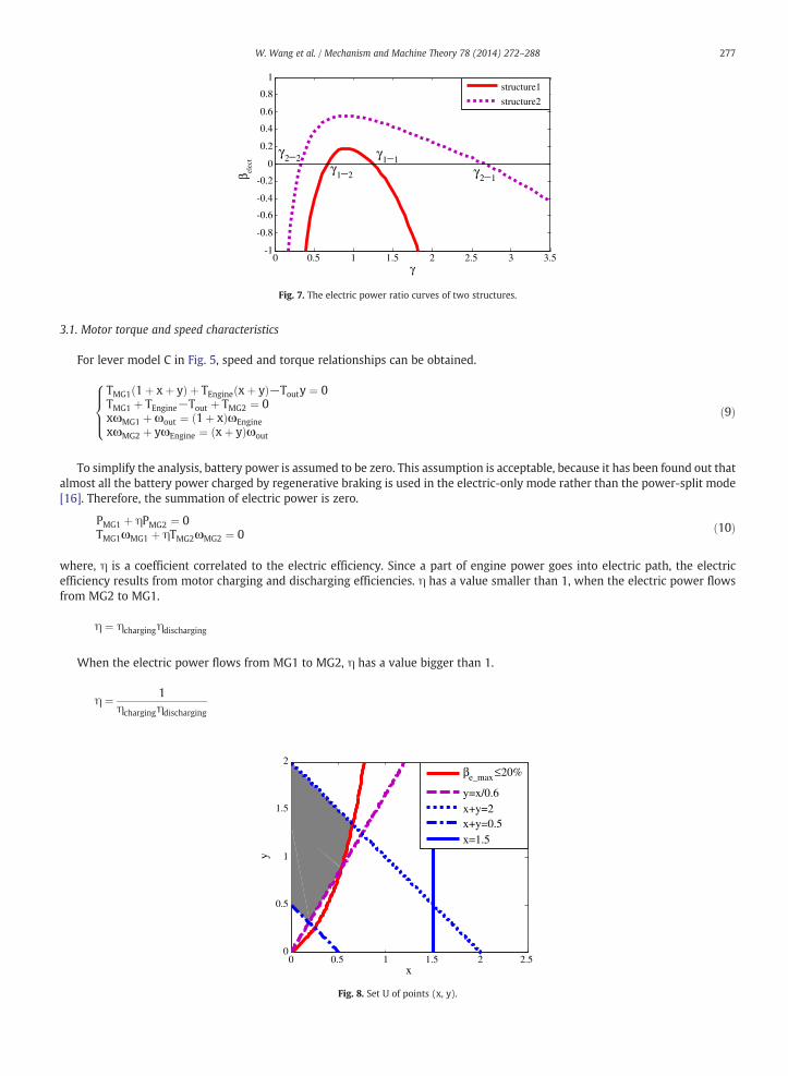
Fig. 7. The electric power ratio curves of two structures.
277W. Wang et al. / Mechanism and Machine Theory 78 (2014) 272–288
3.1. Motor torque and speed characteristics
For lever model C in Fig. 5, speed and torque relationships can be obtained.
TMG1 1þ xþ yð Þ þ TEngine xþ yð Þ−Touty ¼ 0TMG1 þ TEngine−Tout þ TMG2 ¼ 0xωMG1 þωout ¼ 1þ xð ÞωEnginexωMG2 þ yωEngine ¼ xþ yð Þωout
8>><>>: ð9Þ
To simplify the analysis, battery power is assumed to be zero. This assumption is acceptable, because it has been found out thatalmost all the battery power charged by regenerative braking is used in the electric-only mode rather than the power-split mode[16]. Therefore, the summation of electric power is zero.
PMG1 þ ηPMG2 ¼ 0TMG1ωMG1 þ ηTMG2ωMG2 ¼ 0 ð10Þ
, η is a coefficient correlated to the electric efficiency. Since a part of engine power goes into electric path, the electric
whereefficiency results from motor charging and discharging efficiencies. η has a value smaller than 1, when the electric power flowsfrom MG2 to MG1.η ¼ ηchargingηdischarging
When the electric power flows from MG1 to MG2, η has a value bigger than 1.
η ¼ 1ηchargingηdischarging
0 0.5 1 1.5 2 2.50
0.5
1
1.5
2
x
y
βe_max ≤20%
y=x/0.6x+y=2x+y=0.5x=1.5
Fig. 8. Set U of points (x, y).

Engine
Out
MG11
x
(a)
Engine
MG1
MG2
1
x+y
(b)
Out
MG1
MG2
1+x
y
(c)
Engine
MG2
x
y
(d)
Out
Fig. 9. Four single lever models derived from lever model C.
278 W. Wang et al. / Mechanism and Machine Theory 78 (2014) 272–288
For simplicity, motor torque and speed are normalized by engine torque and speed respectively, and the following equationsof normalized motor torque and speed are derived from Eqs. (9) and (10).
Table 1Combin
PG2
PG1
(a)(b)(c)(d)
TMG1
TEngine¼ − ηx xþ yð Þ−yγð Þ
η 1þ xð Þ xþ yð Þ−yγð Þ þ y 1þ xð Þγ−1ð ÞTMG2
TEngine¼ x 1þ xð Þγ−1ð Þ
η 1þ xð Þ xþ yð Þ−yγð Þ þ y 1þ xð Þγ−1ð ÞωMG1
ωEngine¼ 1þ xð Þγ−1
xγωMG2
ωEngine¼ xþ yð Þ þ yγ
xγ
8>>>>>>>>>>><>>>>>>>>>>>:
ð11Þ
The expression of TR (γ1) at the first MP (MP1) can be obtained when MG2 speed is zero and MG1 torque is zero.
γ1 ¼ xþ yy
at MP1 ð12Þ
TR (γ2) at second MP (MP2), at which MG1 speed and MG2 torque are zero, can be calculated.
γ2 ¼ 11þ x
at MP2 ð13Þ
Taking derivative of functions in Eq. (11) respectively, the following can be obtained.
ddγ
TMG1
TEngine¼ ηx2y 1þ xþ yð Þ
η 1þ xð Þ xþ yð Þ−yγð Þ þ y 1þ xð Þγ−1ð Þð Þ2 N0
ddγ
TMG2
TEngine¼ 1þ xð Þηx2 1þ xþ yð Þ
η 1þ xð Þ xþ yð Þ−yγð Þ þ y 1þ xð Þγ−1ð Þð Þ2 N0
dωMG1
ωEngine=dγ ¼ 1
xγ2 N0
dωMG2
ωEngine=dγ ¼ − xþ y
xγ2 b0
Generally, the motor torque capacity is limited by its volume, and the wide range of motor speed comes at the price of awell-known decline of efficiency and increase of torque response time at higher motor speed [23]. For the feasibility of levermodel C, the essential conditions are that normalized motor torque should be limited to a boundary value (named as μ in thispaper) and normalized motor speed should be limited to a boundary value (named as σ in this paper) between two MPs. That is,
ations of single lever models derived from lever model C.
(a) (b) (c) (d)
– ① ② ③
① – ④ ⑤
② ④ – ⑥
③ ⑤ ⑥ –

Table 2Compound-split configurations obtained by splitting lever model C.
No. (1) (2) (3) (4) (5) (6)
Lever model
279W.W
anget
al./Mechanism
andMachine
Theory78
(2014)272
–288

280 W. Wang et al. / Mechanism and Machine Theory 78 (2014) 272–288
within the range of [γ2, γ1], the normalized motor torques should be in the range of ‐ μ to μ, and the normalized motor speedsshould be in the range of ‐ σ to σ.
Since x N 0, y N 0, the conclusion that can be drawn from the derivative functions above is that TMG1/TEngine, TMG2/TEngine andωMG1/ωEngine are increasing functions, and ωMG2/ωEngine is a decreasing function. Furthermore, it is known that ωMG1/ωEngine
and TMG2/TEngine are zero when TR (γ) is γ2 at MP2, and ωMG2/ωEngine and TMG1/TEngine are zero when γ = γ1 at MP1. Therefore,when γ2 ≤ γ ≤ γ1, TMG1/TEngine reaches its minimum value at the point of γ = γ2; TMG2/TEngine reaches its maximum value whenγ =γ1; ωMG1/ωEngine comes to its maximum value when γ = γ1; and ωMG2/ωEngine comes to its maximum value when γ = γ2.Based on the limited ranges of motor torques and speeds, the following inequalities can be obtained.
TMG1
TEngine
!min
¼ TMG1
TEngine
�����γ2
¼ − x1þ x
≥−μ ð14Þ
TMG2
TEngine
!max
¼ TMG2
TEngine
�����γ1
¼ xy≤μ ð15Þ
ωMG1
ωEngine
!max
¼ ωMG1
ωEngine
�����γ1
¼ 1þ xð Þγ1−1xγ1
¼ 1þ xþ yxþ y
≤σ ð16Þ
ωMG2
ωEngine
!max
¼ ωMG2
ωEngine
�����γ2
¼ xþ yð Þ‐yγ2
xγ2¼ 1þ xþ y≤σ ð17Þ
Then for lever model C, the value ranges of lever length x and y can be calculated to quantify motor speed and torquecharacteristics.
3.2. Electric power ratio
With PSD, EVT is achieved in HEV by adding an electrical path for power transmitting besides the traditional mechanical path.However, this power splitting also causes the inevitable power loss on the electrical path, which reduces the overall powertrainefficiency. The powertrain efficiency is higher when the power divided into electrical path is smaller. According to the differentroles of two motors MG1 and MG2 in different ranges of TR, the equation of electric power ratio (βelect) of the power divided intoelectrical path (Pelect) to the engine power (PEngine), can be obtained from Eq. (11).
βelect ¼PelectPEngine
¼γ−γ2ð Þ γ1−γð Þ
η γ1−γð Þ þ γ−γ2ð Þ1γ; γ2≤γ≤γ1
η γ−γ2ð Þ γ1−γð Þη γ1−γð Þ þ γ−γ2ð Þ
1γ
γbγ2 or γNγ1
8>><>>: ð18Þ
With two different compound-split structures shown in Fig. 6, the relationship between electric power ratio and MPs will beillustrated. Structure 1 is formed by connecting C1 with C2 and S1 with R2, and engine is positioned at R1, MG1 at S1 (R2), MG2 atS2, and the output shaft at C2 (C1). Structure 2 is formed by connecting R1 with S2 and S1 with C2, and engine is positioned at C1,MG1 at R1, MG2 at R2, and the output shaft at C2 (S1).
Curves of electric power ratio of two structures versus transmission ratio (γ) are plotted with same parameters in Fig. 7,where, γ1− 1 represents TR at the first MP of structure 1, γ1− 2 is TR at the second MP of structure 1, and γ2− 1 and γ2− 2
represent respectively TR at the first and second MPs of structure 2. Fig. 7 shows that structure 1 has lower electric power ratiowhich is less than 20% within the range between two MPs, while the maximum ratio of structure 2 is bigger than 50%.
Engine
Out
MG1
MG2
1
x
y
Engine
MG1
MG2
1
x
x+y
1
PG1 PG2
Out
Fig. 10. Lever model C backward splitting into two single PGs.

0 0.5 1 1.5 2 2.50
0.5
1
1.5
2
x
y
βe_max ≤20%
y=x/0.6x+y=2x+y=0.5x+y=1.5x+y=1/1.5x=1/1.5x=0.25
Fig. 11. Set U1.
281W. Wang et al. / Mechanism and Machine Theory 78 (2014) 272–288
As explained above, efficiency of the electric path is lower than that of the mechanical path. Compared two curves in Fig. 7, theelectric power ratio is affected by the distance between two MPs, which is expressed as γ1/γ2. γ2 ‐ 1/γ2 ‐ 2 N γ1 ‐ 1/γ1 ‐ 2, and themaximum electric power ratio of structure 2 between MPs is higher, the efficiency of structure 2 between MPs is relatively lower.
In order that the compound-split system has high efficiency between two MPs, the electric power ratio should be limited to aboundary value λ within the range γ2 to γ1. Taking derivative of βelect, the following equation can be obtained.
dβelect
dγ¼
ηγ2
γ−γ2ð Þ2 −γ1
γ1−γð Þ2� �
η γγ−γ2ð Þ þ γ
γ1−γ
� �2 ;γ2≤γ≤γ1
γ þγffiffiffiffiffiγ1
q
Within the range γ2–γ1, the maximum of the electric power ratio (βe _ max) is calculated when γ ¼ 1 2 ηγ21þffiffiffiffiffiγ1ηγ2
q .
βe max ¼γ1
γ2−1
� � ffiffiffiffiffiffiffiffiffiγ1
ηγ2
r
ηffiffiffiffiffiffiffiffiffiγ1
ηγ2
rþ 1
� �γ1
γ2þ
ffiffiffiffiffiffiffiffiffiγ1
ηγ2
r� � ð19Þ
Limiting the maximum of electric power ratio to a boundary value λ, βe _ max ≤ λ, the inequality of γ1/γ2 can be obtained.
ffiffiffiffiffiffiγ1
γ2
r¼
ffiffiffiffiffiffiffiffiffiffiffiffiffiffiffiffiffiffiffiffiffiffiffiffiffiffiffiffiffiffixþ yð Þ 1þ xð Þ
y
s≤ λ
ffiffiffiη
p þ ffiffiffiffiffiffiffiffiffiffiffiffiffiffiffiffiffiffiffiffiffiffiffiλþ 1−λη
p1−λη
ð20Þ
R1
C1
S1
S2
C2
R2MG1
MG2 MG2
MG1
Out
Engine Engine
Out
Fig. 12. Lever model of compound-split configuration ①.

282 W. Wang et al. / Mechanism and Machine Theory 78 (2014) 272–288
3.3. Lever model splitting
According to motor speed and torque characteristics, the values of μ and σ vary with the vehicle. For example, μ and σ arebigger in plug-in HEV, this means larger motor and smaller engine. In this paper, μ is 0.6 and σ is 3 for power-split HEV [26]. Then
Table 3All of the possible compound-split configurations.
Combination of two PGs No. Set of points (x,y) Compound-split configuration The tooth number ratio of ringgear to sun gear (k1 and k2)
PG1: (a)PG2: (b)
(1) U1 k1 ¼ 1x
k2 ¼ xþ y
PG1: (a)PG2: (c)
(2) U2 k1 ¼ 1x
k2 ¼ 1þxy
PG1: (a)PG2: (d)
(3) U3 k1 ¼ 1x
k2 ¼ yx
PG1: (b)PG2: (c)
(4) U4-1 and U4-2 k1 ¼ xþ yk2 ¼ y
xþ1
k1 ¼ xþ yk2 ¼ 1þx
y
(5)

Table 3 (continued)
Combination of two PGs No. Set of points (x,y) Compound-split configuration The tooth number ratio of ringgear to sun gear (k1 and k2)
PG1: (b)PG2: (d)
U5-1 and U5-2 k1 ¼ xþ yk2 ¼ y
x
k1 ¼ 1xþy
k2 ¼ yx
PG1: (c)PG2: (d)
(6) U6 k1 ¼ xþ1y
k2 ¼ yx
Table 4Compound-split configurations selected.
No. Compound-split configuration selected K1 and K2
(2) k1 ¼ 1x ¼ 3
k2 ¼ 1þxy ¼ 2
(3) k1 ¼ 1x ¼ 3
k2 ¼ yx ¼ 2
(6) k1 ¼ xþ1y ¼ 2
k2 ¼ yx ¼ 2
283W. Wang et al. / Mechanism and Machine Theory 78 (2014) 272–288
R1
C1
S1 S2
C2
R2
Out
MG1
MG2
Engine
CL1
CL2
R1
C1
S1
S2
C2
R2Engine
MG1
MG2
CL1
CL2Out
R1
C1
S1
S2
C2
R2
MG1
MG2CL1
CL2
Engine
Out
Dual-mode system Dual-mode system Dual-mode system
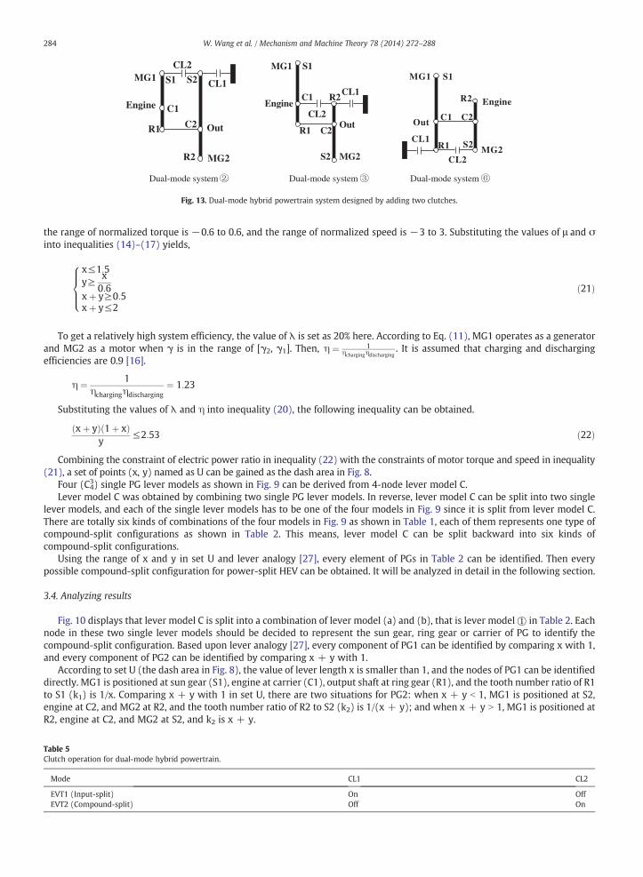
Fig. 13. Dual-mode hybrid powertrain system designed by adding two clutches.
284 W. Wang et al. / Mechanism and Machine Theory 78 (2014) 272–288
the range of normalized torque is −0.6 to 0.6, and the range of normalized speed is −3 to 3. Substituting the values of μ and σinto inequalities (14)–(17) yields,
Table 5Clutch o
Mode
EVT1EVT2
x≤1:5y≥ x
0:6xþ y≥0:5xþ y≤2
8>><>>: ð21Þ
To get a relatively high system efficiency, the value of λ is set as 20% here. According to Eq. (11), MG1 operates as a generatorand MG2 as a motor when γ is in the range of [γ2, γ1]. Then, η ¼ 1
ηchargingηdischarging. It is assumed that charging and discharging
efficiencies are 0.9 [16].
η ¼ 1ηchargingηdischarging
¼ 1:23
Substituting the values of λ and η into inequality (20), the following inequality can be obtained.
xþ yð Þ 1þ xð Þy
≤2:53 ð22Þ
Combining the constraint of electric power ratio in inequality (22) with the constraints of motor torque and speed in inequality(21), a set of points (x, y) named as U can be gained as the dash area in Fig. 8.
Four (C43) single PG lever models as shown in Fig. 9 can be derived from 4-node lever model C.Lever model C was obtained by combining two single PG lever models. In reverse, lever model C can be split into two single
lever models, and each of the single lever models has to be one of the four models in Fig. 9 since it is split from lever model C.There are totally six kinds of combinations of the four models in Fig. 9 as shown in Table 1, each of them represents one type ofcompound-split configurations as shown in Table 2. This means, lever model C can be split backward into six kinds ofcompound-split configurations.
Using the range of x and y in set U and lever analogy [27], every element of PGs in Table 2 can be identified. Then everypossible compound-split configuration for power-split HEV can be obtained. It will be analyzed in detail in the following section.
3.4. Analyzing results
Fig. 10 displays that lever model C is split into a combination of lever model (a) and (b), that is lever model① in Table 2. Eachnode in these two single lever models should be decided to represent the sun gear, ring gear or carrier of PG to identify thecompound-split configuration. Based upon lever analogy [27], every component of PG1 can be identified by comparing x with 1,and every component of PG2 can be identified by comparing x + y with 1.
According to set U (the dash area in Fig. 8), the value of lever length x is smaller than 1, and the nodes of PG1 can be identifieddirectly. MG1 is positioned at sun gear (S1), engine at carrier (C1), output shaft at ring gear (R1), and the tooth number ratio of R1to S1 (k1) is 1/x. Comparing x + y with 1 in set U, there are two situations for PG2: when x + y b 1, MG1 is positioned at S2,engine at C2, and MG2 at R2, and the tooth number ratio of R2 to S2 (k2) is 1/(x + y); and when x + y N 1, MG1 is positioned atR2, engine at C2, and MG2 at S2, and k2 is x + y.
peration for dual-mode hybrid powertrain.
CL1 CL2
(Input-split) On Off(Compound-split) Off On

0 1 2 3 4 5-1
-0.5
0
0.5
1
γ
P MG
1/PE
ngin
e
Compoud-split mode
Input-split mode
(γ3)
mode switching point
γ2 γ1
0 1 2 3 4 5-1
-0.5
0
0.5
1
γ
P MG
1/PE
ngin
e
Compoud-split modeInput-split mode
(γ3)γ1γ2
mode switching point
(a) (b)
Fig. 14. Electric power ratio curves of dual-mode hybrid system.
285W. Wang et al. / Mechanism and Machine Theory 78 (2014) 272–288
In general, for a planetary gear set, the reasonable range of k1 or k2 is between 1.5 and 4 [15,16,26]. Based on the expressions ofk1 and k2 as mentioned above, the inequalities can be obtained as follows.
1:5≤ 1x≤4 and 1:5≤ 1
xþ y≤4 or 1:5≤xþ y≤4 ð23Þ
By taking the intersection set of constraints in inequality (23) and set U, it turns out that there is a new set U1 (the dash area inFig. 11).
U1 ¼ 1:5≤ 1x≤4
� �∩ 1:5≤xþ y≤4ð Þ∩U ð24Þ
In set U1, x + y N 1 and x b 1. So for the lever model in Fig. 10, every element of compound-split configuration ① can beidentified, as shown in Fig. 12.
MG1 is positioned at S1 (R2), engine at C1 (C2), the output shaft at R1, and MG2 at S2 in Fig. 12, and k1 = 1/x, k2 = x + y.Using the same method to analyze the other five kinds of configurations in Table 2, all the possible compound-split
configurations can be obtained as shown in Table 3.All the eight possible compound-split configurations for HEV are found using the analysis method proposed. Each set of points
(x, y) corresponds to one compound-split configuration. Based on the equations of MPs (γ1 and γ2), the values of x and y can becalculated with the values of TR at two MPs which can be positioned at the desired TRs. Then according to the set which point(x, y) is in, one or more configurations which meet the desired MPs can be identified. Meanwhile, the values of k1 and k2 can becalculated with the values of x and y.
0 0.5 1 1.5 2 2.5 3 3.5 4-1
-0.5
0
0.5
1
γ
P MG
1/PE
ngin
e
Compound-split modeInput-split mode
γ2γ3
γ1
mode switching point
Fig. 15. Electric power ratio curves of dual-mode hybrid powertrain with three PGs.

286 W. Wang et al. / Mechanism and Machine Theory 78 (2014) 272–288
What's more, set U in Fig. 8 implies that γ1 and γ2 have maximum boundaries, which can be calculated with Eqs. (12) and(13).
1bγ1 ¼ xþ yy
¼ 1þ xy≤1:6
0:597≤γ2 ¼ 11þ x
b1
)ð25Þ
Condition (25) suggests that the maximum boundary of γ1 is 1.6, and Fig. 7 tells that the electric power ratio increase rapidlywhen TR is away from MPs, so compound-split configuration is suitable for high-speed mode in dual-mode hybrid powertrain.
Using the analysis method proposed in this paper, the compound-split configurations were identified. Then based on each ofthe configurations, two clutches are added to achieve a dual-mode hybrid powertrain.
4. Application in dual-mode HEV
Condition (25) tells that 1 b γ1 ≤ 1.6, so the compound-split configuration is suitable for high-speed mode. In order tooperate efficiently during whole speed range of the vehicle, a dual-mode hybrid powertrain can be designed by combiningcompound-split with input-split.
4.1. Selection of compound-split configuration
For high efficiency of transmission, the mechanical points are designed at the desired TRs at which the vehicle is mainly driven.Based on the transmission specifications of 2009 Chevrolet Silverado Hybrid and some researches [24,25,28,29], the TRs at twoMPs of compound-split mode are positioned around 1.5 and 0.75 generally. So the two MPs can be designed as, γ1 = 1.5 N 1 andγ2 = 0.75 b 1. Based on Eqs. (12) and (13), the values of x and y can be calculated.
γ1 ¼ xþ yy
¼ 1:5
γ2 ¼ 11þ x
¼ 0:75
The value of x is 0.33, and y is 0.66. According to the analyzing results in Table 3, point (0.33, 0.66) drops in set U2, U3 and U6,which correspond to compound-split configuration ②, ③ and ⑥ as shown in Table 4 respectively. k1 and k2 of eachcompound-split configuration can be calculated.
4.2. Design of dual-mode hybrid powertrain
Using the compound-split configurations selected, the dual-mode hybrid powertrain can be designed by adding two clutchesor two clutches plus a PG.
When a dual-mode hybrid powertrain is achieved with two PGs, it can be designed by adding two clutches to one of thecompound-split configurations obtained above, as shown in Fig. 13. In addition, the dual-mode hybrid powertrain works incompound-split mode or input-split mode by engaging and disengaging the clutches as shown in Table 5.
Fig. 14 shows the electric power ratio curves of the three dual-mode systems in Fig. 13. For dual-mode systems ② and ③ inFig. 13, it can be observed that the TR (γ3) at MP of input-split mode is equal to the TR (γ2) at the second MP of compound-splitmode as shown in Fig. 14(a). However, system ③ could already be judged infeasible based on its configuration since it isunreasonable that the engine speed has to drop to zero rapidly at the point of mode switching. For dual-mode system ⑥, the MPof input-split mode (γ3) is equal to the first MP in compound-split mode (γ1) as shown in Fig. 14(b). For system②, Fig. 14(a) tellsthat, to the left of the mode switching point, compound-split and input-split are quite similar; to the right of the mode switchingpoint, the power-splitting of compound-split is much bigger than that of input-split at low vehicle speed. It makes no sense tobuild a dual-mode system like this since compound-split does not show any advantage in it. For system ⑥, it can be concluded
R1
C1
S1 S2
C2
R2
Out
MG1
MG2
Engine
CL1
CL2R1
C1
S1
S2
C2
R2Engine
MG1
MG2
CL2Out
CL1
R1
C1
S1
S2
C2
R2
MG1
Engine
Out
MG2 CL1
CL2
Dual-mode system Dual-mode system Dual-mode system
Fig. 16. Dual-mode hybrid powertrains designed by adding a PG and two clutches.

0 0.5 1 1.5 2 2.5 3 3.5 4 4.5 5-2
-1.5
-1
-0.5
0
0.5
1
1.5
2
2.5
3
γN
orm
aliz
ed m
otor
spe
ed
ωMG2/ωEngine
ωMG2/ωEngine
ωMG1/ωEngine
ωMG1/ωEngine
γ3γ1γ2
mode switching point
:
:
:
:
Fig. 17. MG1 and MG2 normalized speed of dual-mode hybrid powertrain with three PGs.
287W. Wang et al. / Mechanism and Machine Theory 78 (2014) 272–288
from Fig. 14(b) that, in order to reduce the amount of power splitting over the whole speed range of the vehicle, dual-modehybrid system works in compound-split mode to the left of the mode switching point at high vehicle speed, and in input-splitmode to the right of the mode switching point at low vehicle speed. Therefore, only dual-mode hybrid system ⑥ is feasible forpower-split HEV.
When a dual-mode hybrid system is achieved with three PGs, it can be designed by adding a PG and two clutches to one of thecompound-split configurations in Table 4. This kind of dual-mode system has three MPs and the MP of input-split mode (γ3) isbigger than the first MP of compound-split mode (γ1). The electric power ratio curves of the dual-mode system are shown inFig. 15. This kind of dual-mode system can reduce the amount of power splitting over larger speed range of the vehicle than thedual-mode system with two PGs.
For the perfect combination of compound-split and input-split, Fig. 15 suggests the relationship of three MPs and the modeswitching point as follows.
γ3NγCNγ1Nγ2 ð26Þ
, γC is the TR at the mode switching point, at which one mode switches to the other mode by engaging and disengaging the
whereclutches.The dual-mode hybrid systems with three PGs can be obtained by adding a PG and two clutches to each of the compound-splitconfigurations selected as shown in Fig. 16.
According to the kinematic characteristics of dual-mode hybrid systems in Fig. 16, the curves of MG1 and MG2 normalizedspeed can be obtained as Fig. 17. Furthermore, the curves in Fig. 17 imply that both sides of all the clutches are at the samevelocity at the mode switching point, which means that the two modes switch into each other without clutch slipping.
5. Conclusion
In this study, a systematic methodology of analysis on compound-split configurations was proposed. Eight suitablecompound-split configurations for power-split HEV were identified. The torque and speed among the four powertrain elementsand power split ratio were expressed with lever length x and y. A set of points (x, y) was figured out to get the best motor speed,torque and power-split characteristics. Based on the range of x and y, the 4-node lever model was backward split into two singlelever models to identify the inner connection of compound-split configuration. According to the one-to-one correspondencebetween compound-split configuration and the set of point (x, y), the compound-split configuration could be determined directlybased on the position of point (x, y), which could be calculated with the values of TRs at two MPs (γ1 and γ2). It was concludedthat compound-split mode can be used as high-speed mode in dual-mode hybrid system and the application of this analysismethod in dual-mode hybrid system was explained. Using this method, three compound-split configurations were selected bysetting two MPs at the typical TRs of dual-mode HEVs, γ1 = 1.5 and γ2 = 0.75. Furthermore, dual-mode hybrid powertrainstructures were designed using the compound-split configurations selected.
References
[1] Chao Ma, Minseok Song, Jian Ji, Jungman Park, Sungyeon Ko, Hyunsoo Kim, Comparative study on power characteristics and control strategies for plug-inHEV, Vehicle Power and Propulsion Conference (VPPC)IEEE, 2011, pp. 1–6, http://dx.doi.org/10.1109/VPPC.2011.6043156, (IEEE, 2011).
[2] J. KIM, J. KANG, Y. KIM, T. Kim, B. Min, H. Kim, Design of power split transmission: design of dual mode power split transmission, Int. J. Automot. Technol. 11(4) (2010) 565–571.
[3] Tim M. Grewe, Brendan M. Conlon, Alan G. Holmes, Defining the General Motors 2-mode hybrid transmission, SAE Technical Paper 2007-01-0273 (2007),http://dx.doi.org/10.4271/2007-01-0273.
[4] Brendan Conlon. Comparative analysis of single and combined hybrid electrically variable transmission operating modes. SAE paper, No: 2005-01-1162.[5] A.K. Gupta, C.P. Ramanarayanan, Analysis of circulating power within hybrid electric vehicle transmissions, Mech. Mach. Theory 64 (June 2013) 131–143.[6] E.I. Radzimovsky, A simplified approach for determining power losses and efficiency of planetary gear drives, Mach. Des. 28 (3) (1956) 101–110.

288 W. Wang et al. / Mechanism and Machine Theory 78 (2014) 272–288
[7] F. Bottiglione, S. De Pinto, G. Mantriota, Infinitely variable transmissions in neutral gear: torque ratio and power re-circulation, Mech. Mach. Theory 74 (April2014) 285–298.
[8] F. Bottiglione, G. Mantriota, Effect of the ratio spread of CVU in automotive kinetic energy recovery systems, J. Mech. Des. 135 (6) (2013) 061001.[9] M. Cammalleri, Efficiency of split-way CVT's. A simplified model, SAE Trans. J. Engines 116 (2008) 1656–1664 (No. 2007-24-0133).
[10] F. Bottiglione, G. Mantriota, Reversibility of power-split transmissions, J. Mech. Des. 133 (8) (2011) 084503.[11] Antonio Rossetti, Alarico Macor, Multi-objective optimization of hydro-mechanical power split transmissions, Mech. Mach. Theory 62 (April 2013) 112–128.[12] J.R. Gomà Ayats, J. Vivancos Calvet, J. Minguella Canela, U. Diego-Ayala, F. Fenollosa Artes, Power transmitted through a particular branch in mechanisms
comprising planetary gear trains and other fixed or variable transmissions, Mech. Mach. Theory 46 (2011) 1744–1754.[13] G. Mantriota, Comments on “Power transmitted through a particular branch in mechanisms comprising planetary gear trains and other fixed or variable
transmissions”, Mech. Mach. Theory 73 (March 2014) 101–102.[14] D.J. Sanger, The determination of power flow in multiple-path transmission systems, Mech. Mach. Theory 7 (1972) 103–109.[15] H. Yang, S. CHO, N. KIM, W. LIM, S. CHA, Analysis of planetary gear hybrid powertrain system part 1: input split system, Int. J. Automot. Technol. 8 (6) (2007)
771–780.[16] H. Yang, B. Kim, Y. Park, W. LIM, S. CHA, Analysis of planetary gear hybrid powertrain system part 2: output split system, Int. J. Automot. Technol. 10 (3)
(2009) 381–390, http://dx.doi.org/10.1007/s12239-009-0044-y.[17] Kukhyun Ahn, Sungtae Cho, Wonsik Lim, Yeong-il Park, Jang Moo Lee, Performance analysis and parametric design of the dual-mode planetary gear hybrid
powertrain, Proc. IMechE 220 (2006), http://dx.doi.org/10.1243/09544070JAUTO334 (Part D: J. Automobile Engineering).[18] Madhusudan Raghavan, The analysis of planetary gear trains, ASME J. Mech. Robot. (May 2010), http://dx.doi.org/10.1115/1.4001092.[19] Ettore Pennestri, Lorenzo Mariti, Pier Paolo Valentini, Victor H. Mucin, Efficiency Evaluation of Gearboxes for Parallel Hybrid Vehicles: Theory and
Applications, Mech. Mach. Theory 49 (2012) 157–176.[20] Behrooz Mashadi, Seyed A.M. Emadi, Dual-mode power split transmission for hybrid electric vehicles, IEEE Trans. Veh. Technol. 59 (2010) 3223–3232.[21] M. Schulz, Circulating mechanical power in a power-split hybrid electric vehicle transmission, Proc. Inst. Mech. Eng. Part D J. Automob. Eng. 218 (2004)
1419, http://dx.doi.org/10.1243/0954407042707759.[22] Brendan M. Conlon. Output-split electrically-variable transmission with two planetary gear sets and two motor/Generators. U.S. Patent Pub. No.: US 2010/
0227722 A1.[23] Michael A. Miller, Alan G. Holmes, Brendan M. Conlon, Peter J. Savagian. The GM “Voltec” 4ET50 Multi-Mode Electric Transaxle. SAE 2011-01-0887. DOI: 10.
4271/2011-01-0887.[24] N. Kim, J. Kwon, A. Rousseau, Trade-off between multi-mode powertrain complexity and fuel consumption, The 25th World Battery, Hybrid and Fuel Cell
Electric Vehicle Symposium & Exhibition. EVS-25 Shenzhen, China, Nov 5–9 2010.[25] J. Kang, W. Choi, S. Hong, J. Park, H. Kim, Control strategy for dual-mode power split HEV considering transmission efficiency, IEEE Vehicle Power and
Propulsion Conference (VPPC), 2011, pp. 1–6, http://dx.doi.org/10.1109/VPPC.2011.6043008.[26] Yuan Shi-hua, Liu Hong, Peng Zeng, Wei Bin Xiong, Analysis of the compound split transmission based on the four-port power split device, J. Beijing Inst.
Technol. 21 (1) (2012) 50–57.[27] L. Howard, Maurice Benford, B. Leising, The Lever Analogy: a new tool in transmission analysis, SAE Tech. Pap. 810102 (1981), http://dx.doi.org/10.4271/
810102.[28] Dekun Pei, Michael Leamy, Forward-looking simulation of the GM front-wheel drive two-mode power-split HEV using a dynamic programming-informed
equivalent cost minimization strategy, SAE Int. J. Alt. Power. 2 (2) (2013) 379–390, http://dx.doi.org/10.4271/2013-01-0815.[29] Kukhyun Ahn, SukWon Cha, Developing mode shift strategies for a two-mode hybrid powertrain with fixed gears, SAE Int. J. Passeng. Cars - Mech. Syst. 1 (1)
(2009) 285–292, http://dx.doi.org/10.4271/2008-01-0307.

本文献由“学霸图书馆-文献云下载”收集自网络,仅供学习交流使用。
学霸图书馆(www.xuebalib.com)是一个“整合众多图书馆数据库资源,
提供一站式文献检索和下载服务”的24 小时在线不限IP
图书馆。
图书馆致力于便利、促进学习与科研,提供最强文献下载服务。
图书馆导航:
图书馆首页 文献云下载 图书馆入口 外文数据库大全 疑难文献辅助工具