media flange - california institute of technology€¦ · robot option media flange for product...
TRANSCRIPT

Robot Option
Media Flange
For Product Family LBR iiwa
Assembly and Operating Instructions
KUKA Roboter GmbH
Issued: 29.02.2016
Version: Option Media Flange V7
Media Flange

Media Flange
2 / 195 Issued: 29.02.2016 Version: Option Media Flange V7
© Copyright 2016
KUKA Roboter GmbH
Zugspitzstraße 140
D-86165 Augsburg
Germany
This documentation or excerpts therefrom may not be reproduced or disclosed to third parties without the express permission of KUKA Roboter GmbH.
Other functions not described in this documentation may be operable in the controller. The user has no claims to these functions, however, in the case of a replacement or service work.
We have checked the content of this documentation for conformity with the hardware and software described. Nevertheless, discrepancies cannot be precluded, for which reason we are not able to guarantee total conformity. The information in this documentation is checked on a regular basis, how-ever, and necessary corrections will be incorporated in the subsequent edition.
Subject to technical alterations without an effect on the function.
Translation of the original documentation
KIM-PS5-DOC
Publication: Pub Option Medien-Flansch (PDF) en
Book structure: Option Medien-Flansch V4.1
Version: Option Media Flange V7

Contents
Contents
1 Introduction .................................................................................................. 7
1.1 Documentation for the options ................................................................................... 7
1.2 Representation of warnings and notes ...................................................................... 7
1.3 Terms used ................................................................................................................ 7
1.4 Trademarks ................................................................................................................ 8
2 Purpose ........................................................................................................ 9
2.1 Target group .............................................................................................................. 9
2.2 Intended use .............................................................................................................. 9
3 Product description ..................................................................................... 11
3.1 Media flange overview ............................................................................................... 11
3.1.1 Basic flange .......................................................................................................... 11
3.1.2 Media flange electrical .......................................................................................... 12
3.1.3 Media flange pneumatic ........................................................................................ 12
3.1.4 Media flange IO pneumatic ................................................................................... 13
3.1.5 Media flange Touch pneumatic ............................................................................. 13
3.1.6 Media flange Touch electrical ............................................................................... 15
3.1.7 Media flange IO electrical ..................................................................................... 16
3.1.8 Media flange IO valve pneumatic ......................................................................... 17
3.1.9 Media flange Inside electrical ............................................................................... 18
3.1.10 Media flange Inside pneumatic ............................................................................. 18
4 Technical data .............................................................................................. 21
4.1 Technical data – overview ......................................................................................... 21
4.2 Technical data, basic flange ...................................................................................... 25
4.2.1 Basic data, basic flange ........................................................................................ 25
4.2.2 Dimensions, basic flange ...................................................................................... 26
4.2.3 Identification plate, basic flange ............................................................................ 26
4.2.4 Payloads, basic flange .......................................................................................... 27
4.2.5 Working envelope, basic flange ............................................................................ 30
4.3 Technical data, media flange electrical ...................................................................... 31
4.3.1 Basic data, media flange electrical ....................................................................... 31
4.3.2 Dimensions, media flange electrical ..................................................................... 32
4.3.3 Identification plate, MF electrical .......................................................................... 32
4.3.4 Payloads, media flange electrical ......................................................................... 33
4.3.5 Working envelope, media flange electrical ........................................................... 36
4.4 Technical data, media flange pneumatic ................................................................... 37
4.4.1 Basic data, media flange pneumatic ..................................................................... 37
4.4.2 Dimensions, media flange pneumatic ................................................................... 38
4.4.3 Identification plate, MF pneumatic ........................................................................ 38
4.4.4 Payloads, media flange pneumatic ....................................................................... 39
4.4.5 Working envelope, media flange pneumatic ......................................................... 42
4.5 Technical data, media flange IO pneumatic ............................................................... 43
4.5.1 Basic data, media flange IO pneumatic ................................................................ 43
4.5.2 Dimensions, media flange IO pneumatic .............................................................. 44
4.5.3 Identification plate, MF IO pneumatic ................................................................... 44
3 / 195Issued: 29.02.2016 Version: Option Media Flange V7

4 / 195
Media Flange
4.5.4 Payloads, media flange IO pneumatic .................................................................. 45
4.5.5 Working envelope, media flange IO pneumatic .................................................... 48
4.6 Technical data, media flange Touch pneumatic ........................................................ 49
4.6.1 Basic data, media flange Touch pneumatic .......................................................... 49
4.6.2 Dimensions, media flange Touch pneumatic ........................................................ 50
4.6.3 Identification plate, MF Touch pneumatic ............................................................. 50
4.6.4 Payloads, media flange Touch pneumatic ............................................................ 51
4.6.5 Working envelope, media flange Touch pneumatic .............................................. 54
4.7 Technical data, media flange Touch electrical .......................................................... 56
4.7.1 Basic data, media flange Touch electrical ............................................................ 56
4.7.2 Dimensions, media flange Touch electrical .......................................................... 56
4.7.3 Identification plate, MF Touch electrical ............................................................... 57
4.7.4 Payloads, media flange Touch electrical .............................................................. 57
4.7.5 Working envelope, media flange Touch electrical ................................................ 60
4.8 Technical data, media flange IO electrical ................................................................. 62
4.8.1 Basic data, media flange IO electrical .................................................................. 62
4.8.2 Dimensions, media flange IO electrical ................................................................ 62
4.8.3 Identification plate, MF IO electrical ..................................................................... 63
4.8.4 Payloads, media flange IO electrical .................................................................... 63
4.8.5 Working envelope, media flange IO electrical ...................................................... 66
4.9 Technical data, media flange IO valve pneumatic ..................................................... 68
4.9.1 Basic data, media flange IO valve pneumatic ...................................................... 68
4.9.2 Dimensions, media flange IO valve pneumatic .................................................... 69
4.9.3 Identification plate, MF IO valve pneumatic .......................................................... 69
4.9.4 Payloads, media flange IO valve pneumatic ........................................................ 69
4.9.5 Working envelope, media flange IO valve pneumatic .......................................... 72
4.10 Technical data, media flange Inside electrical ........................................................... 74
4.10.1 Basic data, media flange Inside electrical ............................................................ 74
4.10.2 Dimensions, media flange Inside electrical .......................................................... 75
4.10.3 Identification plate, MF Inside electrical ................................................................ 75
4.10.4 Payloads, media flange Inside electrical .............................................................. 76
4.10.5 Working envelope, media flange Inside electrical ................................................ 79
4.11 Technical data, media flange Inside pneumatic ........................................................ 80
4.11.1 Basic data, media flange Inside pneumatic .......................................................... 80
4.11.2 Dimensions, media flange Inside pneumatic ........................................................ 81
4.11.3 Identification plate, MF Inside pneumatic ............................................................. 81
4.11.4 Payloads, media flange Inside pneumatic ............................................................ 82
4.11.5 Working envelope, media flange Inside pneumatic .............................................. 85
4.12 Stopping distances and times .................................................................................... 86
4.12.1 General information .............................................................................................. 86
4.12.2 Terms used .......................................................................................................... 87
4.12.3 Stopping distances and stopping times for LBR iiwa 7 R800 ............................... 89
4.12.3.1 Stopping distances and stopping times for STOP 0, axis 1 to axis 4 .............. 89
4.12.3.2 Stopping distances and stopping times for STOP 1, axis 1 ............................ 90
4.12.3.3 Stopping distances and stopping times for STOP 1, axis 2 ............................ 92
4.12.3.4 Stopping distances and stopping times for STOP 1, axis 3 ............................ 94
4.12.3.5 Stopping distances and stopping times for STOP 1, axis 4 ............................ 96
4.12.4 Stopping distances and stopping times for LBR iiwa 14 R820 ............................. 97
4.12.4.1 Stopping distances and stopping times for STOP 0, axis 1 to axis 4 .............. 98
Issued: 29.02.2016 Version: Option Media Flange V7

Contents
4.12.4.2 Stopping distances and stopping times for STOP 1, axis 1 ............................. 99
4.12.4.3 Stopping distances and stopping times for STOP 1, axis 2 ............................. 101
4.12.4.4 Stopping distances and stopping times for STOP 1, axis 3 ............................. 103
4.12.4.5 Stopping distances and stopping times for STOP 1, axis 4 ............................. 105
4.12.5 Stopping distances and stopping times for LBR iiwa 7 R800 ............................... 106
4.12.5.1 Stopping distances and stopping times for STOP 0, axis 1 to axis 4 .............. 107
4.12.5.2 Stopping distances and stopping times for STOP 1, axis 1 ............................. 108
4.12.5.3 Stopping distances and stopping times for STOP 1, axis 2 ............................. 110
4.12.5.4 Stopping distances and stopping times for STOP 1, axis 3 ............................. 112
4.12.5.5 Stopping distances and stopping times for STOP 1, axis 4 ............................. 114
4.12.6 Stopping distances and stopping times for LBR iiwa 14 R820 ............................. 115
4.12.6.1 Stopping distances and stopping times for STOP 0, axis 1 to axis 4 .............. 116
4.12.6.2 Stopping distances and stopping times for STOP 1, axis 1 ............................. 117
4.12.6.3 Stopping distances and stopping times for STOP 1, axis 2 ............................. 119
4.12.6.4 Stopping distances and stopping times for STOP 1, axis 3 ............................. 121
4.12.6.5 Stopping distances and stopping times for STOP 1, axis 4 ............................. 123
5 Safety ............................................................................................................ 125
5.1 Safety of the option .................................................................................................... 125
5.2 Applied norms and regulations .................................................................................. 125
6 Planning ....................................................................................................... 127
6.1 Interfaces on A1 ......................................................................................................... 127
6.2 Media flange interfaces, overview .............................................................................. 128
6.2.1 Media flange electrical .......................................................................................... 130
6.2.1.1 Interface, media flange electrical ..................................................................... 130
6.2.1.2 Wiring diagrams, media flange electrical ......................................................... 131
6.2.2 Media flange pneumatic ........................................................................................ 134
6.2.2.1 Interface, media flange pneumatic ................................................................... 134
6.2.2.2 Wiring diagrams, media flange pneumatic ....................................................... 135
6.2.3 Media flange IO pneumatic ................................................................................... 136
6.2.3.1 Interface, media flange IO pneumatic .............................................................. 136
6.2.3.2 Wiring diagrams, media flange IO pneumatic .................................................. 138
6.2.4 Media flange Touch pneumatic ............................................................................. 141
6.2.4.1 Interface, media flange Touch pneumatic ........................................................ 141
6.2.4.2 Wiring diagrams, media flange Touch pneumatic ............................................ 143
6.2.5 Media flange Touch electrical ............................................................................... 144
6.2.5.1 Interface, media flange Touch pneumatic ........................................................ 144
6.2.5.2 Wiring diagrams, media flange Touch electrical .............................................. 147
6.2.6 Media flange IO electrical ..................................................................................... 150
6.2.6.1 Interface, media flange IO electrical ................................................................ 150
6.2.6.2 Wiring diagrams, media flange IO electrical .................................................... 152
6.2.7 Media flange IO valve pneumatic ......................................................................... 156
6.2.7.1 Interface, media flange IO valve pneumatic .................................................... 156
6.2.7.2 Wiring diagrams, media flange IO valve pneumatic ........................................ 159
6.2.8 Media flange Inside electrical ............................................................................... 162
6.2.8.1 Interface, media flange Inside electrical .......................................................... 162
6.2.8.2 Wiring diagrams, media flange Inside electrical .............................................. 162
6.2.9 Media flange Inside pneumatic ............................................................................. 164
6.2.9.1 Interface, media flange Inside pneumatic ........................................................ 164
5 / 195Issued: 29.02.2016 Version: Option Media Flange V7

6 / 195
Media Flange
6.2.9.2 Wiring diagrams, media flange Inside pneumatic ............................................ 165
6.2.10 Connector bypack X651 ....................................................................................... 165
6.2.11 Data cable ............................................................................................................ 166
6.2.12 Tool connector, media flange Inside electrical ..................................................... 167
6.2.13 Tool connector, media flange Inside pneumatic ................................................... 168
7 Transportation ............................................................................................. 171
8 Configuration ............................................................................................... 173
8.1 Overview .................................................................................................................... 173
8.1.1 Media flange configuration ................................................................................... 173
9 Maintenance ................................................................................................. 175
9.1 Maintenance .............................................................................................................. 175
9.2 Cleaning .................................................................................................................... 175
10 Repair ............................................................................................................ 177
10.1 Repair ........................................................................................................................ 177
11 Troubleshooting .......................................................................................... 179
11.1 Troubleshooting, media flange IO pneumatic, media flange Touch pneumatic ......... 179
12 Decommissioning, storage and disposal .................................................. 181
12.1 Decommissioning ...................................................................................................... 181
12.2 Storage ...................................................................................................................... 181
12.3 Disposal ..................................................................................................................... 181
13 KUKA Service ............................................................................................... 183
13.1 Requesting support ................................................................................................... 183
13.2 KUKA Customer Support ........................................................................................... 183
Index ............................................................................................................. 191
Issued: 29.02.2016 Version: Option Media Flange V7

1 Introduction
1 Introduction
1.1 Documentation for the options
The documentation for this option consists of the following parts:
Assembly and operating instructions for this option
Assembly and operating instructions for the higher-level system
Each of these sets of instructions is a separate document.
1.2 Representation of warnings and notes
Safety These warnings are relevant to safety and must be observed.
This warning draws attention to procedures which serve to prevent or remedy emergencies or malfunctions:
Notices These notices serve to make your work easier or contain references to further information.
1.3 Terms used
t
t
These warnings mean that it is certain or highly probable that death or severe injuries will occur, if no precautions
are taken.
These warnings mean that death or severe injuries may occur, if no precautions are taken.
These warnings mean that minor injuries may occur, if no precautions are taken.
These warnings mean that damage to property may oc-cur, if no precautions are taken.
These warnings contain references to safety-relevant information or general safety measures. These warnings do not refer to individual hazards or individual pre-
cautionary measures.
Procedures marked with this warning must be followed exactly.
Tip to make your work easier or reference to further information.
Term Description
DTM Device Type Manager
EtherCAT EtherCAT is an Ethernet-based field bus.
MF Media flange
7 / 195Issued: 29.02.2016 Version: Option Media Flange V7

8 / 195
Media Flange
1.4 Trademarks
EtherCAT® is a registered trademark and patented technology, licensed by Beckhoff Automation GmbH, Germany.
Issued: 29.02.2016 Version: Option Media Flange V7

2 Purpose
2 Purpose
2.1 Target group
This documentation is aimed at users with the following knowledge and skills:
Advanced knowledge of mechanical engineering
Advanced knowledge of electrical and electronic systems
Knowledge of the robot controller system
2.2 Intended use
Use The media flange is a universal interface that enables the user to connect elec-trical and pneumatic components to the robot flange, to configure them via the robot program and to access the internal energy supply system of the robot.
Misuse Any use or application deviating from the intended use is deemed to be imper-missible misuse. This includes e.g.:
Operation outside the permissible operating parameters
Operation in potentially explosive environments
Outdoor operation
Underground operation
2
s
For optimal use of our products, we recommend that our customers take part in a course of training at KUKA College. Information about the training program can be found at www.kuka.com or can be ob-
tained directly from our subsidiaries.
Changing the structure of the manipulator, e.g. by drilling holes, etc., can result in damage to the components. This
is considered improper use and leads to loss of guarantee and liability enti-tlements.
9 / 195Issued: 29.02.2016 Version: Option Media Flange V7

10 / 195
Media Flange
Issued: 29.02.2016 Version: Option Media Flange V7

3 Product description
3 Product description
3.1 Media flange overview
Description The following media flanges are available:
3.1.1 Basic flange
Overview
Description The basic flange has a hole pattern conforming to DIN ISO 9409-1-50-7-M6. The basic flange has no additional connection options.
t
s
Media flange Description
Basic flange (>>> 3.1.1 "Basic flange" Page 11)
Media flange electrical (>>> 3.1.2 "Media flange electrical" Page 12)
Media flange pneumatic (>>> 3.1.3 "Media flange pneumatic" Page 12)
Media flange IO pneu-matic
(>>> 3.1.4 "Media flange IO pneumatic" Page 13)
Media flange Touch pneu-matic
(>>> 3.1.5 "Media flange Touch pneumatic" Page 13)
Media flange Touch elec-trical
(>>> 3.1.6 "Media flange Touch electrical" Page 15)
Media flange IO electrical (>>> 3.1.7 "Media flange IO electrical" Page 16)
Media flange IO valve pneumatic
(>>> 3.1.8 "Media flange IO valve pneu-matic" Page 17)
Media flange Inside elec-trical
(>>> 3.1.9 "Media flange Inside electrical" Page 18)
Media flange Inside pneu-matic
(>>> 3.1.10 "Media flange Inside pneumatic" Page 18)
Fig. 3-1: Basic flange
11 / 195Issued: 29.02.2016 Version: Option Media Flange V7

12 / 195
Media Flange
3.1.2 Media flange electrical
Overview
Description The media flange electrical is a universal interface that enables the user to connect electrical components to the robot flange.
The media flange electrical has a hole pattern conforming to DIN ISO 9409-1-50-7-M6.
The media flange electrical offers the following expansions:
Connections for two supply voltages are available.
Two interfaces for analog signals and CAT5 data transfer are available.
3.1.3 Media flange pneumatic
Overview
Description The media flange pneumatic is a universal interface that enables the user to connect pneumatic and electrical components to the robot flange.
The media flange pneumatic has a hole pattern conforming to DIN ISO 9409-1-50-7-M6.
The media flange pneumatic offers the following expansions:
Pneumatic interface with two compressed air connections.
Connection for a supply voltage.
An interface for analog signals and CAT5 is available.
Fig. 3-2: Media flange electrical
The electrical interface must be supplied by an external power or data source and not by the robot controller.
Fig. 3-3: Media flange pneumatic
The electrical interface must be supplied by an external power or data source and not by the robot controller.
Issued: 29.02.2016 Version: Option Media Flange V7

3 Product description
3.1.4 Media flange IO pneumatic
Overview
Description The media flange IO pneumatic is a universal interface that enables the user to connect electrical and pneumatic components to the robot flange.
The media flange IO pneumatic has a hole pattern conforming to DIN ISO 9409-1-50-7-M6.
The media flange IO pneumatic offers the following expansions:
Configurable inputs and outputs for direct connection of sensors and other electrical components.
Connection for a supply voltage.
Connection of additional EtherCAT bus devices.
Pneumatic interface with two compressed air connections.
3.1.5 Media flange Touch pneumatic
Overview
Fig. 3-4: Media flange IO pneumatic
The media flange IO pneumatic is supplied with power by the robot controller. No external power or data source is required. Data cable X650, X651 is required for operation.
Fig. 3-5: Media flange Touch pneumatic
1 LED strip
2 Enabling switch
3 Application button
13 / 195Issued: 29.02.2016 Version: Option Media Flange V7

14 / 195
Media Flange
Description The media flange Touch pneumatic is a universal interface that enables the user to connect electrical and pneumatic components to the robot flange.
The media flange Touch pneumatic has a hole pattern conforming to DIN ISO 9409-1-50-7-M6.
The media flange Touch pneumatic offers the following expansions:
Configurable inputs and outputs for direct connection of sensors and other electrical components.
Connection for a supply voltage.
Additional EtherCAT devices can be connected.
Pneumatic interface with two compressed air connections.
Enabling switch
Programmable application button
Programmable visual indication
Handle for manual guidance
Function LED strip
2 light rings
Blue (freely configurable)
Red/green (reserved internally)
Switching speed:
Application-specific, min. change of state every 25 ms
Enabling switch
The enabling switch has 3 positions:
Not pressed
Center position
Fully pressed (panic position)
The enabling switch must be held in the center position in operating modes T1, T2 and CRR in order to be able to jog the manipulator.
By default, the enabling switch has no function in Automatic mode.
Application button
The application button is freely programmable.
Switching states:
OFF (0): Application button is not pressed
ON (1): Application button is pressed
Switching speeds:
Application-specific, scanning of the input values every 25 ms
The media flange Touch pneumatic is supplied with power by the ro-bot controller. No external power or data source is required. Data ca-ble X650, X651 is required.
Debouncing is not carried out for any inputs.
Issued: 29.02.2016 Version: Option Media Flange V7

3 Product description
3.1.6 Media flange Touch electrical
Overview
Description The media flange Touch electrical is a universal interface that enables the user to connect electrical components to the robot flange.
The media flange Touch electrical has a hole pattern conforming to DIN ISO 9409-1-50-7-M6.
The media flange Touch electrical offers the following expansions:
Configurable inputs and outputs for direct connection of sensors and other electrical components.
Connection for two supply voltages.
Additional EtherCAT devices can be connected.
Additional interface for analog signals and CAT5.
Enabling switch
Programmable application button
Programmable visual indication
Handle for manual guidance
Function LED strip
2 light rings
Blue (freely configurable)
Red/green (reserved internally)
Switching speed:
Application-specific, min. change of state every 25 ms
Enabling switch
The enabling switch has 3 positions:
Not pressed
Fig. 3-6: Media flange Touch electrical
1 Enabling switch
2 Application button
3 LED strip
The media flange Touch electrical is supplied with power by the robot controller. Data cable X650, X651 is required. The interfaces X74 and X75 must be supplied by an external power or data source and not by
the robot controller.
15 / 195Issued: 29.02.2016 Version: Option Media Flange V7

16 / 195
Media Flange
Center position
Fully pressed (panic position)
The enabling switch must be held in the center position in operating modes T1, T2 and CRR in order to be able to jog the manipulator.
By default, the enabling switch has no function in Automatic mode.
Application button
The application button is freely programmable.
Switching states:
OFF (0): Application button is not pressed
ON (1): Application button is pressed
Switching speeds:
Application-specific, scanning of the input values every 25 ms
3.1.7 Media flange IO electrical
Overview
Description The media flange IO electrical is a universal interface that enables the user to connect electrical components to the robot flange.
The media flange IO electrical has a hole pattern conforming to DIN ISO 9409-1-50-7-M6.
The media flange IO electrical offers the following expansions:
Configurable inputs and outputs for direct connection of sensors and other electrical components.
Connection for two supply voltages.
Connection of additional EtherCAT bus devices.
Additional interface for analog signals and CAT5.
Debouncing is not carried out for any inputs.
Fig. 3-7: Media flange IO electrical
Issued: 29.02.2016 Version: Option Media Flange V7

3 Product description
3.1.8 Media flange IO valve pneumatic
Overview
Description The media flange IO valve pneumatic is a universal interface that enables the user to connect electrical and pneumatic components to the robot flange.
The media flange IO valve pneumatic has a hole pattern conforming to DIN ISO 9409-1-50-7-M6.
The media flange IO valve pneumatic offers the following expansions:
Configurable inputs and outputs for direct connection of sensors and other electrical components.
Connection for a supply voltage.
Connection of additional EtherCAT bus devices.
Intelligent pneumatic interface: Two integrated bistable valves and an ad-ditional air connection.
The media flange IO electrical is supplied with power by the robot controller. Data cable X650, X651 is required for operation. No exter-nal power or data source is required. The interfaces X44 and X45
must be supplied by an external power or data source and not by the robot controller.
Fig. 3-8: Media flange IO valve pneumatic
The media flange IO valve pneumatic is supplied with power by the robot controller. No external power or data source is required. Data cable X650, X651 is required for operation.
17 / 195Issued: 29.02.2016 Version: Option Media Flange V7

18 / 195
Media Flange
3.1.9 Media flange Inside electrical
Overview
Description The media flange Inside electrical is a universal interface that enables the user to connect electrical components to the robot flange.
The media flange Inside electrical has a hole pattern conforming to DIN ISO 9409-1-50-7-M6.
The media flange Inside electrical offers the following expansions:
Connections for two supply voltages are available.
Two interfaces for analog signals and CAT5 data transfer are available.
Internally fitted connector
3.1.10 Media flange Inside pneumatic
Overview
Description The media flange Inside pneumatic is a universal interface that enables the user to connect pneumatic and electrical components to the robot flange.
The media flange Inside pneumatic has a hole pattern conforming to DIN ISO 9409-1-50-7-M6.
Fig. 3-9: Media flange Inside electrical
The electrical interface must be supplied by an external power or data source and not by the robot controller.
Fig. 3-10: Media flange Inside pneumatic
Issued: 29.02.2016 Version: Option Media Flange V7

3 Product description
The media flange Inside pneumatic offers the following expansions:
Pneumatic interface with two compressed air connections.
Connection for a supply voltage.
An interface for analog signals and CAT5 is available.
Internal connector
The electrical interface must be supplied by an external power or data source and not by the robot controller.
19 / 195Issued: 29.02.2016 Version: Option Media Flange V7

20 / 195
Media Flange
Issued: 29.02.2016 Version: Option Media Flange V7

4 Technical data
4 Technical data
4.1 Technical data – overview
Overview The technical data of the individual media flanges can be found in the following sections:
4
T
t
Media flange Technical Data
Basic flange Technical Data
(>>> 4.2.1 "Basic data, basic flange" Page 25)
Dimensions
(>>> 4.2.2 "Dimensions, basic flange" Page 26)
Identification plate
(>>> 4.2.3 "Identification plate, basic flange" Page 26)
Payloads
(>>> 4.2.4 "Payloads, basic flange" Page 27)
Working envelope
(>>> 4.2.5 "Working envelope, basic flange" Page 30)
Stopping distances and times
(>>> 4.12 "Stopping distances and times" Page 86)
Media flange electrical
Technical Data
(>>> 4.3.1 "Basic data, media flange electrical" Page 31)
Dimensions
(>>> 4.3.2 "Dimensions, media flange electrical" Page 32)
Identification plate
(>>> 4.3.3 "Identification plate, MF electrical" Page 32)
Payloads
(>>> 4.3.4 "Payloads, media flange electrical" Page 33)
Working envelope
(>>> 4.3.5 "Working envelope, media flange elec-trical" Page 36)
Stopping distances and times
(>>> 4.12 "Stopping distances and times" Page 86)
21 / 195Issued: 29.02.2016 Version: Option Media Flange V7

22 / 195
Media Flange
Media flange pneumatic
Technical Data
(>>> 4.4.1 "Basic data, media flange pneumatic" Page 37)
Dimensions
(>>> 4.4.2 "Dimensions, media flange pneumatic" Page 38)
Identification plate
(>>> 4.4.3 "Identification plate, MF pneumatic" Page 38)
Payloads
(>>> 4.4.4 "Payloads, media flange pneumatic" Page 39)
Working envelope
(>>> 4.4.5 "Working envelope, media flange pneu-matic" Page 42)
Stopping distances and times
(>>> 4.12 "Stopping distances and times" Page 86)
Media flange IO pneumatic
Technical Data
(>>> 4.5.1 "Basic data, media flange IO pneumatic" Page 43)
Dimensions
(>>> 4.5.2 "Dimensions, media flange IO pneumat-ic" Page 44)
Identification plate
(>>> 4.5.3 "Identification plate, MF IO pneumatic" Page 44)
Payloads
(>>> 4.5.4 "Payloads, media flange IO pneumatic" Page 45)
Working envelope
(>>> 4.5.5 "Working envelope, media flange IO pneumatic" Page 48)
Stopping distances and times
(>>> 4.12 "Stopping distances and times" Page 86)
Media flange Technical Data
Issued: 29.02.2016 Version: Option Media Flange V7

4 Technical data
Media flange Touch pneu-matic
Technical Data
(>>> 4.6.1 "Basic data, media flange Touch pneu-matic" Page 49)
Dimensions
(>>> 4.6.2 "Dimensions, media flange Touch pneu-matic" Page 50)
Identification plate
(>>> 4.6.3 "Identification plate, MF Touch pneu-matic" Page 50)
Payloads
(>>> 4.6.4 "Payloads, media flange Touch pneu-matic" Page 51)
Working envelope
(>>> 4.6.5 "Working envelope, media flange Touch pneumatic" Page 54)
Stopping distances and times
(>>> 4.12 "Stopping distances and times" Page 86)
Media flange Touch electrical
Technical Data
(>>> 4.7.1 "Basic data, media flange Touch electri-cal" Page 56)
Dimensions
(>>> Fig. 4-51 )
Identification plate
(>>> 4.7.3 "Identification plate, MF Touch electri-cal" Page 57)
Payloads
(>>> 4.7.4 "Payloads, media flange Touch electri-cal" Page 57)
Working envelope
(>>> 4.7.5 "Working envelope, media flange Touch electrical" Page 60)
Stopping distances and times
(>>> 4.12 "Stopping distances and times" Page 86)
Media flange Technical Data
23 / 195Issued: 29.02.2016 Version: Option Media Flange V7

24 / 195
Media Flange
Media flange IO electrical
Technical Data
(>>> 4.8.1 "Basic data, media flange IO electrical" Page 62)
Dimensions
(>>> 4.8.2 "Dimensions, media flange IO electrical" Page 62)
Identification plate
(>>> 4.8.3 "Identification plate, MF IO electrical" Page 63)
Payloads
(>>> 4.8.4 "Payloads, media flange IO electrical" Page 63)
Working envelope
(>>> 4.8.5 "Working envelope, media flange IO electrical" Page 66)
Stopping distances and times
(>>> 4.12 "Stopping distances and times" Page 86)
Media flange IO valve pneumatic
Technical Data
(>>> 4.9.1 "Basic data, media flange IO valve pneumatic" Page 68)
Dimensions
(>>> 4.9.2 "Dimensions, media flange IO valve pneumatic" Page 69)
Identification plate
(>>> 4.9.3 "Identification plate, MF IO valve pneu-matic" Page 69)
Payloads
(>>> 4.9.4 "Payloads, media flange IO valve pneu-matic" Page 69)
Working envelope
(>>> 4.9.5 "Working envelope, media flange IO valve pneumatic" Page 72)
Stopping distances and times
(>>> 4.12 "Stopping distances and times" Page 86)
Media flange Technical Data
Issued: 29.02.2016 Version: Option Media Flange V7

4 Technical data
4.2 Technical data, basic flange
4.2.1 Basic data, basic flange
General
Media flange Inside electrical
Technical Data
(>>> 4.10.1 "Basic data, media flange Inside elec-trical" Page 74)
Dimensions
(>>> 4.10.2 "Dimensions, media flange Inside elec-trical" Page 75)
Identification plate
(>>> 4.10.3 "Identification plate, MF Inside electri-cal" Page 75)
Payloads
(>>> 4.10.4 "Payloads, media flange Inside electri-cal" Page 76)
Working envelope
(>>> 4.10.5 "Working envelope, media flange In-side electrical" Page 79)
Stopping distances and times
(>>> 4.12 "Stopping distances and times" Page 86)
Media flange Inside pneu-matic
Technical Data
(>>> 4.11.1 "Basic data, media flange Inside pneu-matic" Page 80)
Dimensions
(>>> 4.11.2 "Dimensions, media flange Inside pneumatic" Page 81)
Identification plate
(>>> 4.11.3 "Identification plate, MF Inside pneu-matic" Page 81)
Payloads
(>>> 4.11.4 "Payloads, media flange Inside pneu-matic" Page 82)
Working envelope
(>>> 4.11.5 "Working envelope, media flange In-side pneumatic" Page 85)
Stopping distances and times
(>>> 4.12 "Stopping distances and times" Page 86)
Media flange Technical Data
Media flange Basic flange
Weight 230 g
EMC resistance EN 61000-6-2 and EN 61000-6-4
The weight of the media flange is automatically taken into consider-ation by Sunrise.OS.
25 / 195Issued: 29.02.2016 Version: Option Media Flange V7

26 / 195
Media Flange
Ambient condi-
tions
4.2.2 Dimensions, basic flange
The media flange is depicted with axis 7 in the zero position. The symbol Xm indicates the position of the locating element in the zero position.
4.2.3 Identification plate, basic flange
The following identification plate is attached to the media flange. It must not be removed or rendered illegible. Illegible plates and labels must be replaced.
Operation +5 °C to +45 °C (278 K to 318 K)
Storage and transportation -25 °C … +70 °C (248 K … 343 K)
Air humidity 20% … 80%
Protection rating of the media flange IP 54
Ready for operation, with connect-ing cables plugged in (according to EN 60529)
Fig. 4-1: Dimensions, basic flange
Fig. 4-2: Rating plate
1 Article number of the media flange
2 Designation of the media flange
Issued: 29.02.2016 Version: Option Media Flange V7

4 Technical data
4.2.4 Payloads, basic flange
Payloads LBR iiwa 7 R800
Load center of
gravity
For all payloads, the load center of gravity refers to the distance from the face of the mounting flange on axis A7.
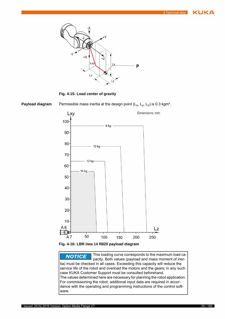
Payload diagram Permissible mass inertia at the design point (Lx, Ly, Lz) is 0.3 kgm².
Robot LBR iiwa 7 R800
Wrist IW
Rated payload 7 kg
Distance of the load center of gravity Lz 60 mm
Distance of the load center of gravity Lxy 35 mm
Permissible moment of inertia 0.3 kgm2
Max. total load 7 kg
Supplementary load None
Fig. 4-3: Load center of gravity
27 / 195Issued: 29.02.2016 Version: Option Media Flange V7

28 / 195
Media Flange
LBR iiwa 14 R820
Load center of
gravity
For all payloads, the load center of gravity refers to the distance from the face of the mounting flange on axis A7.
Fig. 4-4: LBR iiwa 7 R800 payload diagram
Robot LBR iiwa 14 R820
Wrist IW
Rated payload 14 kg
Distance of the load center of gravity Lz 44 mm
Distance of the load center of gravity Lxy 40 mm
Permissible moment of inertia 0.3 kgm2
Max. total load 14 kg
Supplementary load None
Issued: 29.02.2016 Version: Option Media Flange V7

4 Technical data
Payload diagram Permissible mass inertia at the design point (Lx, Ly, Lz) is 0.3 kgm².
Fig. 4-5: Load center of gravity
Fig. 4-6: LBR iiwa 14 R820 payload diagram
This loading curve corresponds to the maximum load ca-pacity. Both values (payload and mass moment of iner-
tia) must be checked in all cases. Exceeding this capacity will reduce the service life of the robot and overload the motors and the gears; in any such case KUKA Customer Support must be consulted beforehand.The values determined here are necessary for planning the robot application. For commissioning the robot, additional input data are required in accor-dance with the operating and programming instructions of the control soft-ware.
29 / 195Issued: 29.02.2016 Version: Option Media Flange V7

30 / 195
Media Flange
Supplementary
load
The robot cannot carry a supplementary load.
4.2.5 Working envelope, basic flange
The diagram shows the shape and size of the working envelope for the robot with the basic flange:
LBR iiwa 7 R800
LBR iiwa 14 R820
Fig. 4-7: Working envelope, LBR iiwa 7 R800, side view
Fig. 4-8: LBR iiwa 7 R800 working envelope, top view
Issued: 29.02.2016 Version: Option Media Flange V7

4 Technical data
4.3 Technical data, media flange electrical
4.3.1 Basic data, media flange electrical
General
Fig. 4-9: Working envelope, LBR iiwa 14 R820, side view
Fig. 4-10: LBR iiwa 14 R820 working envelope, top view
Media flange Media flange electrical
Weight 230 g
EMC resistance EN 61000-6-2 and EN 61000-6-4
31 / 195Issued: 29.02.2016 Version: Option Media Flange V7

32 / 195
Media Flange
Ambient condi-
tions
4.3.2 Dimensions, media flange electrical
The media flange is depicted with axis 7 in the zero position. The symbol Xm indicates the position of the locating element in the zero position.
4.3.3 Identification plate, MF electrical
The following identification plate is attached to the media flange. It must not be removed or rendered illegible. Illegible plates and labels must be replaced.
The weight of the media flange is automatically taken into consider-ation by Sunrise.OS.
Operation +5 °C to +45 °C (278 K to 318 K)
Storage and transportation -25 °C … +70 °C (248 K … 343 K)
Air humidity 20% … 80%
Protection rating of the media flange IP 54
Ready for operation, with connect-ing cables plugged in (according to EN 60529)
Fig. 4-11: Dimensions, media flange electrical
Fig. 4-12: Rating plate
1 Article number of the media flange
2 Designation of the media flange
Issued: 29.02.2016 Version: Option Media Flange V7

4 Technical data
4.3.4 Payloads, media flange electrical
Payloads LBR iiwa 7 R800
Load center of
gravity
For all payloads, the load center of gravity refers to the distance from the face of the mounting flange on axis A7.
Payload diagram Permissible mass inertia at the design point (Lx, Ly, Lz) is 0.3 kgm².
Robot LBR iiwa 7 R800
Wrist IW
Rated payload 7 kg
Distance of the load center of gravity Lz 60 mm
Distance of the load center of gravity Lxy 35 mm
Permissible moment of inertia 0.3 kgm2
Max. total load 7 kg
Supplementary load None
Fig. 4-13: Load center of gravity
33 / 195Issued: 29.02.2016 Version: Option Media Flange V7

34 / 195
Media Flange
LBR iiwa 14 R820
Load center of
gravity P
For all payloads, the load center of gravity refers to the distance from the face of the mounting flange on axis A7.
Fig. 4-14: LBR iiwa 7 R800 payload diagram
Robot LBR iiwa 14 R820
Wrist IW
Rated payload 14 kg
Distance of the load center of gravity Lz 44 mm
Distance of the load center of gravity Lxy 40 mm
Permissible moment of inertia 0.3 kgm2
Max. total load 14 kg
Supplementary load None
Issued: 29.02.2016 Version: Option Media Flange V7
4 Technical data
Payload diagram Permissible mass inertia at the design point (Lx, Ly, Lz) is 0.3 kgm².
Fig. 4-15: Load center of gravity
Fig. 4-16: LBR iiwa 14 R820 payload diagram
This loading curve corresponds to the maximum load ca-pacity. Both values (payload and mass moment of iner-
tia) must be checked in all cases. Exceeding this capacity will reduce the service life of the robot and overload the motors and the gears; in any such case KUKA Customer Support must be consulted beforehand.The values determined here are necessary for planning the robot application. For commissioning the robot, additional input data are required in accor-dance with the operating and programming instructions of the control soft-ware.
35 / 195Issued: 29.02.2016 Version: Option Media Flange V7

36 / 195
Media Flange
Supplementary
load
The robot cannot carry a supplementary load.
4.3.5 Working envelope, media flange electrical
The diagram shows the shape and size of the working envelope for the robot with the media flange electrical:
LBR iiwa 7 R800
LBR iiwa 14 R820
Fig. 4-17: Working envelope, LBR iiwa 7 R800, side view
Fig. 4-18: LBR iiwa 7 R800 working envelope, top view
Issued: 29.02.2016 Version: Option Media Flange V7

4 Technical data
4.4 Technical data, media flange pneumatic
4.4.1 Basic data, media flange pneumatic
General
Fig. 4-19: Working envelope, LBR iiwa 14 R820, side view
Fig. 4-20: LBR iiwa 14 R820 working envelope, top view
Media flange Media flange pneumatic
Weight 230 g
EMC resistance EN 61000-6-2 and EN 61000-6-4
37 / 195Issued: 29.02.2016 Version: Option Media Flange V7

38 / 195
Media Flange
Ambient condi-
tions
4.4.2 Dimensions, media flange pneumatic
The media flange is depicted with axis 7 in the zero position. The symbol Xm indicates the position of the locating element in the zero position.
4.4.3 Identification plate, MF pneumatic
The following identification plate is attached to the media flange. It must not be removed or rendered illegible. Illegible plates and labels must be replaced.
The weight of the media flange is automatically taken into consider-ation by Sunrise.OS.
Operation +5 °C to +45 °C (278 K to 318 K)
Storage and transportation -25 °C … +70 °C (248 K … 343 K)
Air humidity 20% … 80%
Protection rating of the media flange IP 54
Ready for operation, with connect-ing cables plugged in (according to EN 60529)
Fig. 4-21: Dimensions, media flange pneumatic
Fig. 4-22: Rating plate
1 Article number of the media flange
2 Designation of the media flange
Issued: 29.02.2016 Version: Option Media Flange V7

4 Technical data
4.4.4 Payloads, media flange pneumatic
Payloads LBR iiwa 7 R800
Load center of
gravity
For all payloads, the load center of gravity refers to the distance from the face of the mounting flange on axis A7.
Payload diagram Permissible mass inertia at the design point (Lx, Ly, Lz) is 0.3 kgm².
Robot LBR iiwa 7 R800
Wrist IW
Rated payload 7 kg
Distance of the load center of gravity Lz 60 mm
Distance of the load center of gravity Lxy 35 mm
Permissible moment of inertia 0.3 kgm2
Max. total load 7 kg
Supplementary load None
Fig. 4-23: Load center of gravity
39 / 195Issued: 29.02.2016 Version: Option Media Flange V7

40 / 195
Media Flange
LBR iiwa 14 R820
Load center of
gravity
For all payloads, the load center of gravity refers to the distance from the face of the mounting flange on axis A7.
Fig. 4-24: LBR iiwa 7 R800 payload diagram
Robot LBR iiwa 14 R820
Wrist IW
Rated payload 14 kg
Distance of the load center of gravity Lz 44 mm
Distance of the load center of gravity Lxy 40 mm
Permissible moment of inertia 0.3 kgm2
Max. total load 14 kg
Supplementary load None
Issued: 29.02.2016 Version: Option Media Flange V7

4 Technical data
Payload diagram Permissible mass inertia at the design point (Lx, Ly, Lz) is 0.3 kgm².
Fig. 4-25: Load center of gravity
Fig. 4-26: LBR iiwa 14 R820 payload diagram
This loading curve corresponds to the maximum load ca-pacity. Both values (payload and mass moment of iner-
tia) must be checked in all cases. Exceeding this capacity will reduce the service life of the robot and overload the motors and the gears; in any such case KUKA Customer Support must be consulted beforehand.The values determined here are necessary for planning the robot application. For commissioning the robot, additional input data are required in accor-dance with the operating and programming instructions of the control soft-ware.
41 / 195Issued: 29.02.2016 Version: Option Media Flange V7

42 / 195
Media Flange
Supplementary
load
The robot cannot carry a supplementary load.
4.4.5 Working envelope, media flange pneumatic
The diagram shows the shape and size of the working envelope for the robot with the media flange pneumatic:
LBR iiwa 7 R800
LBR iiwa 14 R820
Fig. 4-27: Working envelope, LBR iiwa 7 R800, side view
Fig. 4-28: LBR iiwa 7 R800 working envelope, top view
Issued: 29.02.2016 Version: Option Media Flange V7

4 Technical data
4.5 Technical data, media flange IO pneumatic
4.5.1 Basic data, media flange IO pneumatic
General
Fig. 4-29: Working envelope, LBR iiwa 14 R820, side view
Fig. 4-30: LBR iiwa 14 R820 working envelope, top view
Media flange Media flange IO pneumatic
Weight 230 g
Power supply 18 V…30 V
43 / 195Issued: 29.02.2016 Version: Option Media Flange V7

44 / 195
Media Flange
Ambient condi-
tions
4.5.2 Dimensions, media flange IO pneumatic
The media flange is depicted with axis 7 in the zero position. The symbol Xm indicates the position of the locating element in the zero position.
4.5.3 Identification plate, MF IO pneumatic
The following identification plate is attached to the media flange. It must not be removed or rendered illegible. Illegible plates and labels must be replaced.
Power requirement 2 A for 4 outputs
150 mA for EtherCAT
3 A supply voltage
EMC resistance EN 61000-6-2 and EN 61000-6-4
The weight of the media flange is automatically taken into consider-ation by Sunrise.OS.
Operation +5 °C to +45 °C (278 K to 318 K)
Storage and transportation -25 °C … +70 °C (248 K … 343 K)
Air humidity 20% … 80%
Protection rating of the media flange IP 54
Ready for operation, with connect-ing cables plugged in (according to EN 60529)
Fig. 4-31: Dimensions, media flange IO pneumatic
Issued: 29.02.2016 Version: Option Media Flange V7

4 Technical data
4.5.4 Payloads, media flange IO pneumatic
Payloads LBR iiwa 7 R800
Load center of
gravity
For all payloads, the load center of gravity refers to the distance from the face of the mounting flange on axis A7.
Payload diagram Permissible mass inertia at the design point (Lx, Ly, Lz) is 0.3 kgm².
Fig. 4-32: Rating plate
1 Article number of the media flange
2 Designation of the media flange
Robot LBR iiwa 7 R800
Wrist IW
Rated payload 7 kg
Distance of the load center of gravity Lz 60 mm
Distance of the load center of gravity Lxy 35 mm
Permissible moment of inertia 0.3 kgm2
Max. total load 7 kg
Supplementary load None
Fig. 4-33: Load center of gravity
45 / 195Issued: 29.02.2016 Version: Option Media Flange V7

46 / 195
Media Flange
LBR iiwa 14 R820
Load center of
gravity
For all payloads, the load center of gravity refers to the distance from the face of the mounting flange on axis A7.
Fig. 4-34: LBR iiwa 7 R800 payload diagram
Robot LBR iiwa 14 R820
Wrist IW
Rated payload 14 kg
Distance of the load center of gravity Lz 44 mm
Distance of the load center of gravity Lxy 40 mm
Permissible moment of inertia 0.3 kgm2
Max. total load 14 kg
Supplementary load None
Issued: 29.02.2016 Version: Option Media Flange V7

4 Technical data
Payload diagram Permissible mass inertia at the design point (Lx, Ly, Lz) is 0.3 kgm².
Fig. 4-35: Load center of gravity
Fig. 4-36: LBR iiwa 14 R820 payload diagram
This loading curve corresponds to the maximum load ca-pacity. Both values (payload and mass moment of iner-
tia) must be checked in all cases. Exceeding this capacity will reduce the service life of the robot and overload the motors and the gears; in any such case KUKA Customer Support must be consulted beforehand.The values determined here are necessary for planning the robot application. For commissioning the robot, additional input data are required in accor-dance with the operating and programming instructions of the control soft-ware.
47 / 195Issued: 29.02.2016 Version: Option Media Flange V7
48 / 195
Media Flange
Supplementary
load
The robot cannot carry a supplementary load.
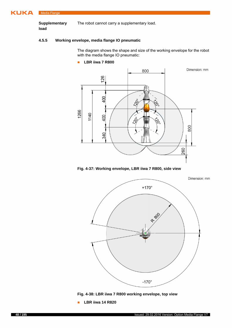
4.5.5 Working envelope, media flange IO pneumatic
The diagram shows the shape and size of the working envelope for the robot with the media flange IO pneumatic:
LBR iiwa 7 R800
LBR iiwa 14 R820
Fig. 4-37: Working envelope, LBR iiwa 7 R800, side view
Fig. 4-38: LBR iiwa 7 R800 working envelope, top view
Issued: 29.02.2016 Version: Option Media Flange V7

4 Technical data
4.6 Technical data, media flange Touch pneumatic
4.6.1 Basic data, media flange Touch pneumatic
General
Fig. 4-39: Working envelope, LBR iiwa 14 R820, side view
Fig. 4-40: LBR iiwa 14 R820 working envelope, top view
Media flange Media flange Touch pneumatic
Weight 458 g
Power supply 18 V…30 V
49 / 195Issued: 29.02.2016 Version: Option Media Flange V7

50 / 195
Media Flange
Ambient condi-
tions
4.6.2 Dimensions, media flange Touch pneumatic
The media flange is depicted with axis 7 in the zero position. The symbol Xm indicates the position of the locating element in the zero position.
4.6.3 Identification plate, MF Touch pneumatic
The following identification plate is attached to the media flange. It must not be removed or rendered illegible. Illegible plates and labels must be replaced.
Power requirement 2 A for 4 outputs
150 mA for EtherCAT
3 A supply voltage
EMC resistance EN 61000-6-2 and EN 61000-6-4
The weight of the media flange is automatically taken into consider-ation by Sunrise.OS.
Operation +5 °C to +45 °C (278 K to 318 K)
Storage and transportation -25 °C … +70 °C (248 K … 343 K)
Air humidity 20% … 80%
Protection rating of the media flange IP 54
Ready for operation, with connect-ing cables plugged in (according to EN 60529)
Fig. 4-41: Dimensions, media flange Touch pneumatic
Issued: 29.02.2016 Version: Option Media Flange V7

4 Technical data
4.6.4 Payloads, media flange Touch pneumatic
Payloads LBR iiwa 7 R800
Load center of
gravity
For all payloads, the load center of gravity refers to the distance from the face of the mounting flange on axis A7.
Payload diagram Permissible mass inertia at the design point (Lx, Ly, Lz) is 0.3 kgm².
Fig. 4-42: Rating plate
1 Article number of the media flange
2 Designation of the media flange
Robot LBR iiwa 7 R800
Wrist IW
Rated payload 7 kg
Distance of the load center of gravity Lz 35 mm
Distance of the load center of gravity Lxy 35 mm
Permissible moment of inertia 0.3 kgm2
Max. total load 7 kg
Supplementary load None
Fig. 4-43: Load center of gravity
51 / 195Issued: 29.02.2016 Version: Option Media Flange V7

52 / 195
Media Flange
LBR iiwa 14 R820
Load center of
gravity
For all payloads, the load center of gravity refers to the distance from the face of the mounting flange on axis A7.
Fig. 4-44: Payload diagram, LBR iiwa 7 R800
Robot LBR iiwa 14 R820
Wrist IW
Rated payload 14 kg
Distance of the load center of gravity Lz 30 mm
Distance of the load center of gravity Lxy 40 mm
Permissible moment of inertia 0.3 kgm2
Max. total load 14 kg
Supplementary load None
Issued: 29.02.2016 Version: Option Media Flange V7

4 Technical data
Payload diagram Permissible mass inertia at the design point (Lx, Ly, Lz) is 0.3 kgm².
Fig. 4-45: Load center of gravity
Fig. 4-46: Payload diagram, LBR iiwa 14 R820
53 / 195Issued: 29.02.2016 Version: Option Media Flange V7

54 / 195
Media Flange
Supplementary
load
The robot cannot carry a supplementary load.
4.6.5 Working envelope, media flange Touch pneumatic
The diagram shows the shape and size of the working envelope for the robot with the media flange Touch pneumatic:
LBR iiwa 7 R800
This loading curve corresponds to the maximum load ca-pacity. Both values (payload and mass moment of iner-
tia) must be checked in all cases. Exceeding this capacity will reduce the service life of the robot and overload the motors and the gears; in any such case KUKA Customer Support must be consulted beforehand.The values determined here are necessary for planning the robot application. For commissioning the robot, additional input data are required in accor-dance with the operating and programming instructions of the control soft-ware.
Fig. 4-47: Working envelope, LBR iiwa 7 R800, side view
Issued: 29.02.2016 Version: Option Media Flange V7

4 Technical data
LBR iiwa 14 R820
Fig. 4-48: LBR iiwa 7 R800 working envelope, top view
Fig. 4-49: Working envelope, LBR iiwa 14 R820, side view
55 / 195Issued: 29.02.2016 Version: Option Media Flange V7

56 / 195
Media Flange
4.7 Technical data, media flange Touch electrical
4.7.1 Basic data, media flange Touch electrical
General
Ambient condi-
tions
4.7.2 Dimensions, media flange Touch electrical
The media flange is depicted with axis 7 in the zero position. The symbol Xm indicates the position of the locating element in the zero position.
Fig. 4-50: LBR iiwa 14 R820 working envelope, top view
Media flange Media flange Touch electrical
Weight 458 g
Power supply 18 V…30 V (internal)
Power requirement 2 A for 4 outputs (internal)
150 mA for EtherCAT (internal)
3 A supply voltage (internal)
EMC resistance EN 61000-6-2 and EN 61000-6-4
The weight of the media flange is automatically taken into consider-ation by Sunrise.OS.
Operation +5 °C to +45 °C (278 K to 318 K)
Storage and transportation -25 °C … +70 °C (248 K … 343 K)
Air humidity 20% … 80%
Protection rating of the media flange IP 54
Ready for operation, with connect-ing cables plugged in (according to EN 60529)
Issued: 29.02.2016 Version: Option Media Flange V7

4 Technical data
4.7.3 Identification plate, MF Touch electrical
The following identification plate is attached to the media flange. It must not be removed or rendered illegible. Illegible plates and labels must be replaced.
4.7.4 Payloads, media flange Touch electrical
Payloads LBR iiwa 7 R800
Load center of
gravity
For all payloads, the load center of gravity refers to the distance from the face of the mounting flange on axis A7.
Fig. 4-51: Dimensions, media flange Touch electrical
Fig. 4-52: Rating plate
1 Article number of the media flange
2 Designation of the media flange
Robot LBR iiwa 7 R800
Wrist IW
Rated payload 7 kg
Distance of the load center of gravity Lz 35 mm
Distance of the load center of gravity Lxy 35 mm
Permissible moment of inertia 0.3 kgm2
Max. total load 7 kg
Supplementary load None
57 / 195Issued: 29.02.2016 Version: Option Media Flange V7

58 / 195
Media Flange
Payload diagram Permissible mass inertia at the design point (Lx, Ly, Lz) is 0.3 kgm².
LBR iiwa 14 R820
Fig. 4-53: Load center of gravity
Fig. 4-54: Payload diagram, LBR iiwa 7 R800
Robot LBR iiwa 14 R820
Wrist IW
Rated payload 14 kg
Distance of the load center of gravity Lz 30 mm
Distance of the load center of gravity Lxy 40 mm
Permissible moment of inertia 0.3 kgm2
Max. total load 14 kg
Supplementary load None
Issued: 29.02.2016 Version: Option Media Flange V7

4 Technical data
Load center of
gravity
For all payloads, the load center of gravity refers to the distance from the face of the mounting flange on axis A7.
Payload diagram Permissible mass inertia at the design point (Lx, Ly, Lz) is 0.3 kgm².
Fig. 4-55: Load center of gravity
Fig. 4-56: Payload diagram, LBR iiwa 14 R820
59 / 195Issued: 29.02.2016 Version: Option Media Flange V7

60 / 195
Media Flange
Supplementary
load
The robot cannot carry a supplementary load.
4.7.5 Working envelope, media flange Touch electrical
The diagram shows the shape and size of the working envelope for the robot with the media flange Touch electrical:
LBR iiwa 7 R800
This loading curve corresponds to the maximum load ca-pacity. Both values (payload and mass moment of iner-
tia) must be checked in all cases. Exceeding this capacity will reduce the service life of the robot and overload the motors and the gears; in any such case KUKA Customer Support must be consulted beforehand.The values determined here are necessary for planning the robot application. For commissioning the robot, additional input data are required in accor-dance with the operating and programming instructions of the control soft-ware.
Fig. 4-57: Working envelope, LBR iiwa 7 R800, side view
Issued: 29.02.2016 Version: Option Media Flange V7

4 Technical data
LBR iiwa 14 R820
Fig. 4-58: LBR iiwa 7 R800 working envelope, top view
Fig. 4-59: Working envelope, LBR iiwa 14 R820, side view
61 / 195Issued: 29.02.2016 Version: Option Media Flange V7

62 / 195
Media Flange
4.8 Technical data, media flange IO electrical
4.8.1 Basic data, media flange IO electrical
General
Ambient condi-
tions
4.8.2 Dimensions, media flange IO electrical
The media flange is depicted with axis 7 in the zero position. The symbol Xm indicates the position of the locating element in the zero position.
Fig. 4-60: LBR iiwa 14 R820 working envelope, top view
Media flange Media flange IO electrical
Weight 230 g
Power supply 18 V…30 V (internal)
Power requirement 2 A for 4 outputs (internal)
150 mA for EtherCAT (internal)
3 A supply voltage (internal)
EMC resistance EN 61000-6-2 and EN 61000-6-4
The weight of the media flange is automatically taken into consider-ation by Sunrise.OS.
Operation +5 °C to +45 °C (278 K to 318 K)
Storage and transportation -25 °C … +70 °C (248 K … 343 K)
Air humidity 20% … 80%
Protection rating of the media flange IP 54
Ready for operation, with connect-ing cables plugged in (according to EN 60529)
Issued: 29.02.2016 Version: Option Media Flange V7

4 Technical data
4.8.3 Identification plate, MF IO electrical
The following identification plate is attached to the media flange. It must not be removed or rendered illegible. Illegible plates and labels must be replaced.
4.8.4 Payloads, media flange IO electrical
Payloads LBR iiwa 7 R800
Load center of
gravity
For all payloads, the load center of gravity refers to the distance from the face of the mounting flange on axis A7.
Fig. 4-61: Dimensions, media flange IO electrical
Fig. 4-62: Rating plate
1 Article number of the media flange
2 Designation of the media flange
Robot LBR iiwa 7 R800
Wrist IW
Rated payload 7 kg
Distance of the load center of gravity Lz 60 mm
Distance of the load center of gravity Lxy 35 mm
Permissible moment of inertia 0.3 kgm2
Max. total load 7 kg
Supplementary load None
63 / 195Issued: 29.02.2016 Version: Option Media Flange V7

64 / 195
Media Flange
Payload diagram Permissible mass inertia at the design point (Lx, Ly, Lz) is 0.3 kgm².
LBR iiwa 14 R820
Fig. 4-63: Load center of gravity
Fig. 4-64: LBR iiwa 7 R800 payload diagram
Robot LBR iiwa 14 R820
Wrist IW
Rated payload 14 kg
Distance of the load center of gravity Lz 44 mm
Distance of the load center of gravity Lxy 40 mm
Permissible moment of inertia 0.3 kgm2
Max. total load 14 kg
Supplementary load None
Issued: 29.02.2016 Version: Option Media Flange V7

4 Technical data
Load center of
gravity
For all payloads, the load center of gravity refers to the distance from the face of the mounting flange on axis A7.
Payload diagram Permissible mass inertia at the design point (Lx, Ly, Lz) is 0.3 kgm².
Fig. 4-65: Load center of gravity
Fig. 4-66: LBR iiwa 14 R820 payload diagram
65 / 195Issued: 29.02.2016 Version: Option Media Flange V7

66 / 195
Media Flange
Supplementary
load
The robot cannot carry a supplementary load.
4.8.5 Working envelope, media flange IO electrical
The diagram shows the shape and size of the working envelope for the robot with the media flange Touch electrical:
LBR iiwa 7 R800
This loading curve corresponds to the maximum load ca-pacity. Both values (payload and mass moment of iner-
tia) must be checked in all cases. Exceeding this capacity will reduce the service life of the robot and overload the motors and the gears; in any such case KUKA Customer Support must be consulted beforehand.The values determined here are necessary for planning the robot application. For commissioning the robot, additional input data are required in accor-dance with the operating and programming instructions of the control soft-ware.
Fig. 4-67: Working envelope, LBR iiwa 7 R800, side view
Issued: 29.02.2016 Version: Option Media Flange V7

4 Technical data
LBR iiwa 14 R820
Fig. 4-68: LBR iiwa 7 R800 working envelope, top view
Fig. 4-69: Working envelope, LBR iiwa 14 R820, side view
67 / 195Issued: 29.02.2016 Version: Option Media Flange V7

68 / 195
Media Flange
4.9 Technical data, media flange IO valve pneumatic
4.9.1 Basic data, media flange IO valve pneumatic
General
Ambient condi-
tions
Fig. 4-70: LBR iiwa 14 R820 working envelope, top view
Media flange Media flange IO valve pneumatic
Weight 458 g
Power supply 18 V…30 V
Power requirement 2 A for 4 outputs
150 mA for EtherCAT
3 A supply voltage
EMC resistance EN 61000-6-2 and EN 61000-6-4
The weight of the media flange is automatically taken into consider-ation by Sunrise.OS.
Operation +5 °C to +45 °C (278 K to 318 K)
Storage and transportation -25 °C … +70 °C (248 K … 343 K)
Air humidity 20% … 80%
Protection rating of the media flange IP 54
Ready for operation, with connect-ing cables plugged in (according to EN 60529)
Issued: 29.02.2016 Version: Option Media Flange V7

4 Technical data
4.9.2 Dimensions, media flange IO valve pneumatic
The media flange is depicted with axis 7 in the zero position. The symbol Xm indicates the position of the locating element in the zero position.
4.9.3 Identification plate, MF IO valve pneumatic
The following identification plate is attached to the media flange. It must not be removed or rendered illegible. Illegible plates and labels must be replaced.
4.9.4 Payloads, media flange IO valve pneumatic
Payloads LBR iiwa 7 R800
Fig. 4-71: Dimensions, media flange IO valve pneumatic
Fig. 4-72: Rating plate
1 Article number of the media flange
2 Designation of the media flange
Robot LBR iiwa 7 R800
Wrist IW
Rated payload 7 kg
Distance of the load center of gravity Lz 35 mm
Distance of the load center of gravity Lxy 35 mm
69 / 195Issued: 29.02.2016 Version: Option Media Flange V7

70 / 195
Media Flange
Load center of
gravity
For all payloads, the load center of gravity refers to the distance from the face of the mounting flange on axis A7.
Payload diagram Permissible mass inertia at the design point (Lx, Ly, Lz) is 0.3 kgm².
LBR iiwa 14 R820
Permissible moment of inertia 0.3 kgm2
Max. total load 7 kg
Supplementary load None
Robot LBR iiwa 7 R800
Fig. 4-73: Load center of gravity
Fig. 4-74: Payload diagram, LBR iiwa 7 R800
Issued: 29.02.2016 Version: Option Media Flange V7

4 Technical data
Load center of
gravity
For all payloads, the load center of gravity refers to the distance from the face of the mounting flange on axis A7.
Payload diagram Permissible mass inertia at the design point (Lx, Ly, Lz) is 0.3 kgm².
Robot LBR iiwa 14 R820
Wrist IW
Rated payload 14 kg
Distance of the load center of gravity Lz 30 mm
Distance of the load center of gravity Lxy 40 mm
Permissible moment of inertia 0.3 kgm2
Max. total load 14 kg
Supplementary load None
Fig. 4-75: Load center of gravity
71 / 195Issued: 29.02.2016 Version: Option Media Flange V7

72 / 195
Media Flange
Supplementary
load
The robot cannot carry a supplementary load.
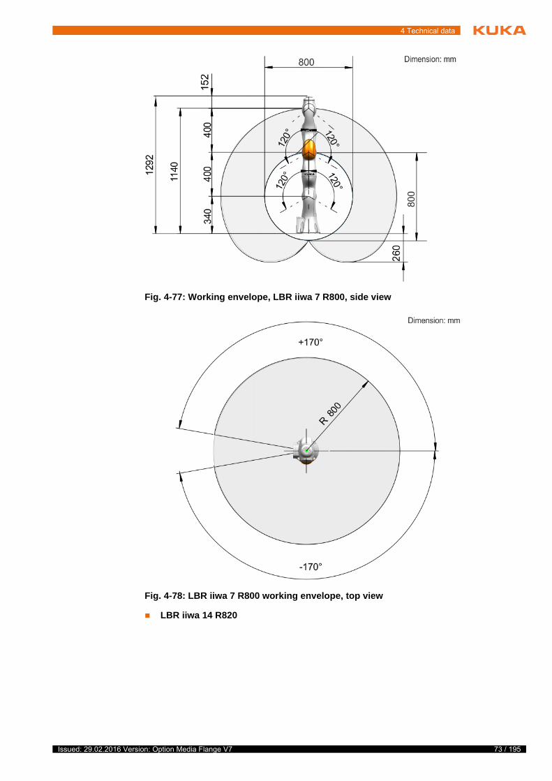
4.9.5 Working envelope, media flange IO valve pneumatic
The diagram shows the shape and size of the working envelope for the robot with the media flange IO valve pneumatic:
LBR iiwa 7 R800
Fig. 4-76: Payload diagram, LBR iiwa 14 R820
This loading curve corresponds to the maximum load ca-pacity. Both values (payload and mass moment of iner-
tia) must be checked in all cases. Exceeding this capacity will reduce the service life of the robot and overload the motors and the gears; in any such case KUKA Customer Support must be consulted beforehand.The values determined here are necessary for planning the robot application. For commissioning the robot, additional input data are required in accor-dance with the operating and programming instructions of the control soft-ware.
Issued: 29.02.2016 Version: Option Media Flange V7
4 Technical data
LBR iiwa 14 R820
Fig. 4-77: Working envelope, LBR iiwa 7 R800, side view
Fig. 4-78: LBR iiwa 7 R800 working envelope, top view
73 / 195Issued: 29.02.2016 Version: Option Media Flange V7

74 / 195
Media Flange
4.10 Technical data, media flange Inside electrical
4.10.1 Basic data, media flange Inside electrical
General
Fig. 4-79: Working envelope, LBR iiwa 14 R820, side view
Fig. 4-80: LBR iiwa 14 R820 working envelope, top view
Media flange Media flange Inside electrical
Weight 230 g
EMC resistance EN 61000-6-2 and EN 61000-6-4
Issued: 29.02.2016 Version: Option Media Flange V7

4 Technical data
Ambient condi-
tions
4.10.2 Dimensions, media flange Inside electrical
The media flange is depicted with axis 7 in the zero position. The symbol Xm indicates the position of the locating element in the zero position.
4.10.3 Identification plate, MF Inside electrical
The following identification plate is attached to the media flange. It must not be removed or rendered illegible. Illegible plates and labels must be replaced.
The weight of the media flange is automatically taken into consider-ation by Sunrise.OS.
The weight of the tool connector is automatically taken into consider-ation by Sunrise.OS.
Operation +5 °C to +45 °C (278 K to 318 K)
Storage and transportation -25 °C … +70 °C (248 K … 343 K)
Air humidity 20% … 80%
Protection rating of the media flange IP 54
Ready for operation, with tool con-nected.
Note: In order to comply with the protection rating IP 54 of the MF, suitable sealing measures must be implemented between the flange and the tool.
Fig. 4-81: Dimensions, media flange Inside electrical
75 / 195Issued: 29.02.2016 Version: Option Media Flange V7

76 / 195
Media Flange
4.10.4 Payloads, media flange Inside electrical
Payloads LBR iiwa 7 R800
Load center of
gravity
For all payloads, the load center of gravity refers to the distance from the face of the mounting flange on axis A7.
Payload diagram Permissible mass inertia at the design point (Lx, Ly, Lz) is 0.3 kgm².
Fig. 4-82: Identification plate
1 Article number of the media flange
2 Designation of the media flange
Robot LBR iiwa 7 R800
Wrist IW
Rated payload 7 kg
Distance of the load center of gravity Lz 60 mm
Distance of the load center of gravity Lxy 35 mm
Permissible moment of inertia 0.3 kgm2
Max. total load 7 kg
Supplementary load None
Fig. 4-83: Load center of gravity
Issued: 29.02.2016 Version: Option Media Flange V7

4 Technical data
LBR iiwa 14 R820
Load center of
gravity
For all payloads, the load center of gravity refers to the distance from the face of the mounting flange on axis A7.
Fig. 4-84: LBR iiwa 7 R800 payload diagram
Robot LBR iiwa 14 R820
Wrist IW
Rated payload 14 kg
Distance of the load center of gravity Lz 44 mm
Distance of the load center of gravity Lxy 40 mm
Permissible moment of inertia 0.3 kgm2
Max. total load 14 kg
Supplementary load None
77 / 195Issued: 29.02.2016 Version: Option Media Flange V7

78 / 195
Media Flange
Payload diagram Permissible mass inertia at the design point (Lx, Ly, Lz) is 0.3 kgm².
Fig. 4-85: Load center of gravity
Fig. 4-86: LBR iiwa 14 R820 payload diagram
This loading curve corresponds to the maximum load ca-pacity. Both values (payload and mass moment of iner-
tia) must be checked in all cases. Exceeding this capacity will reduce the service life of the robot and overload the motors and the gears; in any such case KUKA Customer Support must be consulted beforehand.The values determined here are necessary for planning the robot application. For commissioning the robot, additional input data are required in accor-dance with the operating and programming instructions of the control soft-ware.
Issued: 29.02.2016 Version: Option Media Flange V7

4 Technical data
Supplementary
load
The robot cannot carry a supplementary load.
4.10.5 Working envelope, media flange Inside electrical
The diagram shows the shape and size of the working envelope for the robot with the media flange Inside electrical:
LBR iiwa 7 R800
LBR iiwa 14 R820
Fig. 4-87: Working envelope, LBR iiwa 7 R800, side view
Fig. 4-88: LBR iiwa 7 R800 working envelope, top view
79 / 195Issued: 29.02.2016 Version: Option Media Flange V7

80 / 195
Media Flange
4.11 Technical data, media flange Inside pneumatic
4.11.1 Basic data, media flange Inside pneumatic
General
Fig. 4-89: Working envelope, LBR iiwa 14 R820, side view
Fig. 4-90: LBR iiwa 14 R820 working envelope, top view
Media flange Media flange Inside pneumatic
Weight 230 g
EMC resistance EN 61000-6-2 and EN 61000-6-4
Issued: 29.02.2016 Version: Option Media Flange V7

4 Technical data
Ambient condi-
tions
4.11.2 Dimensions, media flange Inside pneumatic
The media flange is depicted with axis 7 in the zero position. The symbol Xm indicates the position of the locating element in the zero position.
4.11.3 Identification plate, MF Inside pneumatic
The following identification plate is attached to the media flange. It must not be removed or rendered illegible. Illegible plates and labels must be replaced.
The weight of the media flange is automatically taken into consider-ation by Sunrise.OS.
The weight of the tool connector is automatically taken into consider-ation by Sunrise.OS.
Operation +5 °C to +45 °C (278 K to 318 K)
Storage and transportation -25 °C … +70 °C (248 K … 343 K)
Air humidity 20% … 80%
Protection rating of the media flange IP 54
Ready for operation, with connect-ing cables plugged in (according to EN 60529)
Note: In order to comply with the protection rating IP 54 of the MF, suitable sealing measures must be implemented between the flange and the tool.
Fig. 4-91: Dimensions, media flange Inside pneumatic
81 / 195Issued: 29.02.2016 Version: Option Media Flange V7

82 / 195
Media Flange
4.11.4 Payloads, media flange Inside pneumatic
Payloads LBR iiwa 7 R800
Load center of
gravity
For all payloads, the load center of gravity refers to the distance from the face of the mounting flange on axis A7.
Payload diagram Permissible mass inertia at the design point (Lx, Ly, Lz) is 0.3 kgm².
Fig. 4-92: Identification plate
1 Article number of the media flange
2 Designation of the media flange
Robot LBR iiwa 7 R800
Wrist IW
Rated payload 7 kg
Distance of the load center of gravity Lz 60 mm
Distance of the load center of gravity Lxy 35 mm
Permissible moment of inertia 0.3 kgm2
Max. total load 7 kg
Supplementary load None
Fig. 4-93: Load center of gravity
Issued: 29.02.2016 Version: Option Media Flange V7

4 Technical data
LBR iiwa 14 R820
Load center of
gravity
For all payloads, the load center of gravity refers to the distance from the face of the mounting flange on axis A7.
Fig. 4-94: LBR iiwa 7 R800 payload diagram
Robot LBR iiwa 14 R820
Wrist IW
Rated payload 14 kg
Distance of the load center of gravity Lz 44 mm
Distance of the load center of gravity Lxy 40 mm
Permissible moment of inertia 0.3 kgm2
Max. total load 14 kg
Supplementary load None
83 / 195Issued: 29.02.2016 Version: Option Media Flange V7

84 / 195
Media Flange
Payload diagram Permissible mass inertia at the design point (Lx, Ly, Lz) is 0.3 kgm².
Fig. 4-95: Load center of gravity
Fig. 4-96: LBR iiwa 14 R820 payload diagram
This loading curve corresponds to the maximum load ca-pacity. Both values (payload and mass moment of iner-
tia) must be checked in all cases. Exceeding this capacity will reduce the service life of the robot and overload the motors and the gears; in any such case KUKA Customer Support must be consulted beforehand.The values determined here are necessary for planning the robot application. For commissioning the robot, additional input data are required in accor-dance with the operating and programming instructions of the control soft-ware.
Issued: 29.02.2016 Version: Option Media Flange V7

4 Technical data
Supplementary
load
The robot cannot carry a supplementary load.
4.11.5 Working envelope, media flange Inside pneumatic
The diagram shows the shape and size of the working envelope for the robot with the media flange Inside pneumatic:
LBR iiwa 7 R800
LBR iiwa 14 R820
Fig. 4-97: Working envelope, LBR iiwa 7 R800, side view
Fig. 4-98: LBR iiwa 7 R800 working envelope, top view
85 / 195Issued: 29.02.2016 Version: Option Media Flange V7

86 / 195
Media Flange
4.12 Stopping distances and times
4.12.1 General information
Information concerning the position control data:
The stopping distance is the axis angle traveled by the robot from the mo-ment the stop signal is triggered until the robot comes to a complete stand-still.
Fig. 4-99: Working envelope, LBR iiwa 14 R820, side view
Fig. 4-100: LBR iiwa 7 R800 working envelope, top view
Issued: 29.02.2016 Version: Option Media Flange V7
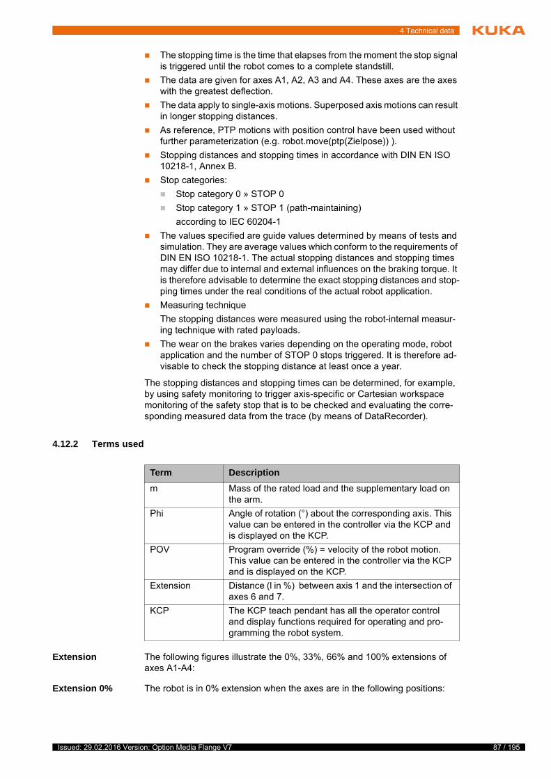
4 Technical data
The stopping time is the time that elapses from the moment the stop signal is triggered until the robot comes to a complete standstill.
The data are given for axes A1, A2, A3 and A4. These axes are the axes with the greatest deflection.
The data apply to single-axis motions. Superposed axis motions can result in longer stopping distances.
As reference, PTP motions with position control have been used without further parameterization (e.g. robot.move(ptp(Zielpose)) ).
Stopping distances and stopping times in accordance with DIN EN ISO 10218-1, Annex B.
Stop categories:
Stop category 0 » STOP 0
Stop category 1 » STOP 1 (path-maintaining)
according to IEC 60204-1
The values specified are guide values determined by means of tests and simulation. They are average values which conform to the requirements of DIN EN ISO 10218-1. The actual stopping distances and stopping times may differ due to internal and external influences on the braking torque. It is therefore advisable to determine the exact stopping distances and stop-ping times under the real conditions of the actual robot application.
Measuring technique
The stopping distances were measured using the robot-internal measur-ing technique with rated payloads.
The wear on the brakes varies depending on the operating mode, robot application and the number of STOP 0 stops triggered. It is therefore ad-visable to check the stopping distance at least once a year.
The stopping distances and stopping times can be determined, for example, by using safety monitoring to trigger axis-specific or Cartesian workspace monitoring of the safety stop that is to be checked and evaluating the corre-sponding measured data from the trace (by means of DataRecorder).
4.12.2 Terms used
Extension The following figures illustrate the 0%, 33%, 66% and 100% extensions of axes A1-A4:
Extension 0% The robot is in 0% extension when the axes are in the following positions:
Term Description
m Mass of the rated load and the supplementary load on the arm.
Phi Angle of rotation (°) about the corresponding axis. This value can be entered in the controller via the KCP and is displayed on the KCP.
POV Program override (%) = velocity of the robot motion. This value can be entered in the controller via the KCP and is displayed on the KCP.
Extension Distance (l in %) between axis 1 and the intersection of axes 6 and 7.
KCP The KCP teach pendant has all the operator control and display functions required for operating and pro-gramming the robot system.
87 / 195Issued: 29.02.2016 Version: Option Media Flange V7

88 / 195
Media Flange
Extension 33%
Axis A1 (J1) A2 (J2) A3 (J4) A4 (J5) A5 (J6) A6 (J7) A7 (J8)
1 0° 0º 0º 0º 0º 0º 0°
2 0° 0° 90° 0° 0° 0° 0°
3 0° 90° 0° 90° 0° 0° 0°
4 0° 90° 0° 90° 90° 0° 0°
Fig. 4-101: Extension 0%, axis 1 - axis 4
Fig. 4-102: Extension 33%, axis 1 - axis 4
Issued: 29.02.2016 Version: Option Media Flange V7

4 Technical data
Extension 66%
Extension 100%
4.12.3 Stopping distances and stopping times for LBR iiwa 7 R800
The stopping distances and stopping times indicated apply to the following media flanges:
Basic flange
Media flange electrical
Media flange pneumatic
Media flange IO pneumatic
Media flange IO electrical
Media flange IO valve pneumatic
4.12.3.1 Stopping distances and stopping times for STOP 0, axis 1 to axis 4
The table shows the stopping distances and stopping times after a STOP 0 (category 0 stop) is triggered. The values refer to the following configuration:
Extension l = 100%
Program override POV = 100%
Mass m = maximum load (rated load + supplementary load on arm)
Fig. 4-103: 66% extension, axis 1 - axis 4
Fig. 4-104: Extension 100%, axis 1 - axis 4
Stopping distance (°) Stopping time (s)
Axis 1 5.193 0.182
Axis 2 5.092 0.212
Axis 3 8.091 0.166
Axis 4 7.538 0.114
89 / 195Issued: 29.02.2016 Version: Option Media Flange V7

90 / 195
Media Flange
4.12.3.2 Stopping distances and stopping times for STOP 1, axis 1
Fig. 4-105: Stopping distances for STOP 1, axis 1
Issued: 29.02.2016 Version: Option Media Flange V7

4 Technical data
Fig. 4-106: Stopping times for STOP 1, axis 1
91 / 195Issued: 29.02.2016 Version: Option Media Flange V7

92 / 195
Media Flange
4.12.3.3 Stopping distances and stopping times for STOP 1, axis 2
Fig. 4-107: Stopping distances for STOP 1, axis 2
Issued: 29.02.2016 Version: Option Media Flange V7

4 Technical data
Fig. 4-108: Stopping times for STOP 1, axis 2
93 / 195Issued: 29.02.2016 Version: Option Media Flange V7

94 / 195
Media Flange
4.12.3.4 Stopping distances and stopping times for STOP 1, axis 3
Fig. 4-109: Stopping distances for STOP 1, axis 3
Issued: 29.02.2016 Version: Option Media Flange V7

4 Technical data
Fig. 4-110: Stopping times for STOP 1, axis 3
95 / 195Issued: 29.02.2016 Version: Option Media Flange V7

96 / 195
Media Flange
4.12.3.5 Stopping distances and stopping times for STOP 1, axis 4
Fig. 4-111: Stopping distances for STOP 1, axis 4
Issued: 29.02.2016 Version: Option Media Flange V7

4 Technical data
4.12.4 Stopping distances and stopping times for LBR iiwa 14 R820
The stopping distances and stopping times indicated apply to the following media flanges:
Fig. 4-112: Stopping times for STOP 1, axis 4
97 / 195Issued: 29.02.2016 Version: Option Media Flange V7

98 / 195
Media Flange
Basic flange
Media flange electrical
Media flange pneumatic
Media flange IO pneumatic
Media flange IO electrical
Media flange IO valve pneumatic
4.12.4.1 Stopping distances and stopping times for STOP 0, axis 1 to axis 4
The table shows the stopping distances and stopping times after a STOP 0 (category 0 stop) is triggered. The values refer to the following configuration:
Extension l = 100%
Program override POV = 100%
Mass m = maximum load (rated load + supplementary load on arm)
Stopping distance (°) Stopping time (s)
Axis 1 5.742 0.188
Axis 2 5.998 0.200
Axis 3 9.323 0.198
Axis 4 3.162 0.092
Issued: 29.02.2016 Version: Option Media Flange V7

4 Technical data
4.12.4.2 Stopping distances and stopping times for STOP 1, axis 1
Fig. 4-113: Stopping distances for STOP 1, axis 1
99 / 195Issued: 29.02.2016 Version: Option Media Flange V7

100 / 195
Media Flange
Fig. 4-114: Stopping times for STOP 1, axis 1
Issued: 29.02.2016 Version: Option Media Flange V7

4 Technical data
4.12.4.3 Stopping distances and stopping times for STOP 1, axis 2
Fig. 4-115: Stopping distances for STOP 1, axis 2
101 / 195Issued: 29.02.2016 Version: Option Media Flange V7

102 / 195
Media Flange
Fig. 4-116: Stopping times for STOP 1, axis 2
Issued: 29.02.2016 Version: Option Media Flange V7

4 Technical data
4.12.4.4 Stopping distances and stopping times for STOP 1, axis 3
Fig. 4-117: Stopping distances for STOP 1, axis 3
103 / 195Issued: 29.02.2016 Version: Option Media Flange V7

104 / 195
Media Flange
Fig. 4-118: Stopping times for STOP 1, axis 3
Issued: 29.02.2016 Version: Option Media Flange V7

4 Technical data
4.12.4.5 Stopping distances and stopping times for STOP 1, axis 4
Fig. 4-119: Stopping distances for STOP 1, axis 4
105 / 195Issued: 29.02.2016 Version: Option Media Flange V7

106 / 195
Media Flange
4.12.5 Stopping distances and stopping times for LBR iiwa 7 R800
The stopping distances and stopping times indicated apply to the following media flange:
Fig. 4-120: Stopping times for STOP 1, axis 4
Issued: 29.02.2016 Version: Option Media Flange V7

4 Technical data
Media flange Touch pneumatic
Media flange Touch electrical
4.12.5.1 Stopping distances and stopping times for STOP 0, axis 1 to axis 4
The table shows the stopping distances and stopping times after a STOP 0 (category 0 stop) is triggered. The values refer to the following configuration:
Extension l = 100%
Program override POV = 100%
Mass m = maximum load (rated load + supplementary load on arm)
Stopping distance (°) Stopping time (s)
Axis 1 8.034 0.184
Axis 2 3.809 0.196
Axis 3 6.155 0.116
Axis 4 9.156 0.150
107 / 195Issued: 29.02.2016 Version: Option Media Flange V7

108 / 195
Media Flange
4.12.5.2 Stopping distances and stopping times for STOP 1, axis 1
Fig. 4-121: Stopping distances for STOP 1, axis 1
Issued: 29.02.2016 Version: Option Media Flange V7
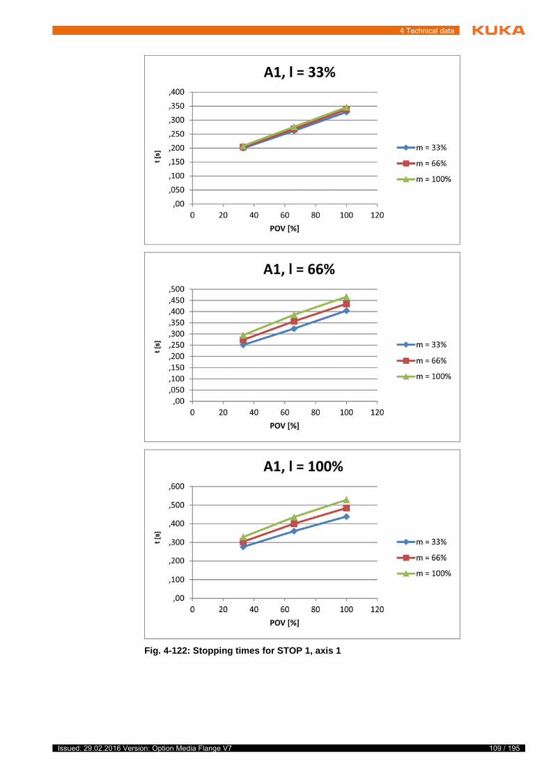
4 Technical data
Fig. 4-122: Stopping times for STOP 1, axis 1
109 / 195Issued: 29.02.2016 Version: Option Media Flange V7
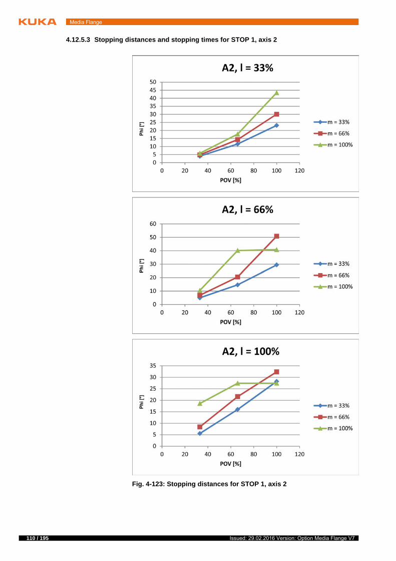
110 / 195
Media Flange
4.12.5.3 Stopping distances and stopping times for STOP 1, axis 2
Fig. 4-123: Stopping distances for STOP 1, axis 2
Issued: 29.02.2016 Version: Option Media Flange V7

4 Technical data
Fig. 4-124: Stopping times for STOP 1, axis 2
111 / 195Issued: 29.02.2016 Version: Option Media Flange V7

112 / 195
Media Flange
4.12.5.4 Stopping distances and stopping times for STOP 1, axis 3
Fig. 4-125: Stopping distances for STOP 1, axis 3
Issued: 29.02.2016 Version: Option Media Flange V7

4 Technical data
Fig. 4-126: Stopping times for STOP 1, axis 3
113 / 195Issued: 29.02.2016 Version: Option Media Flange V7

114 / 195
Media Flange
4.12.5.5 Stopping distances and stopping times for STOP 1, axis 4
Fig. 4-127: Stopping distances for STOP 1, axis 4
Issued: 29.02.2016 Version: Option Media Flange V7

4 Technical data
4.12.6 Stopping distances and stopping times for LBR iiwa 14 R820
The stopping distances and stopping times indicated apply to the following media flange:
Fig. 4-128: Stopping times for STOP 1, axis 4
115 / 195Issued: 29.02.2016 Version: Option Media Flange V7

116 / 195
Media Flange
Media flange Touch pneumatic
Media flange Touch electrical
4.12.6.1 Stopping distances and stopping times for STOP 0, axis 1 to axis 4
The table shows the stopping distances and stopping times after a STOP 0 (category 0 stop) is triggered. The values refer to the following configuration:
Extension l = 100%
Program override POV = 100%
Mass m = maximum load (rated load + supplementary load on arm)
Stopping distance (°) Stopping time (s)
Axis 1 4.51 0.186
Axis 2 7.208 0.206
Axis 3 8.691 0.184
Axis 4 3.53 0.088
Issued: 29.02.2016 Version: Option Media Flange V7

4 Technical data
4.12.6.2 Stopping distances and stopping times for STOP 1, axis 1
Fig. 4-129: Stopping distances for STOP 1, axis 1
117 / 195Issued: 29.02.2016 Version: Option Media Flange V7

118 / 195
Media Flange
Fig. 4-130: Stopping times for STOP 1, axis 1
Issued: 29.02.2016 Version: Option Media Flange V7

4 Technical data
4.12.6.3 Stopping distances and stopping times for STOP 1, axis 2
Fig. 4-131: Stopping distances for STOP 1, axis 2
119 / 195Issued: 29.02.2016 Version: Option Media Flange V7

120 / 195
Media Flange
Fig. 4-132: Stopping times for STOP 1, axis 2
Issued: 29.02.2016 Version: Option Media Flange V7

4 Technical data
4.12.6.4 Stopping distances and stopping times for STOP 1, axis 3
Fig. 4-133: Stopping distances for STOP 1, axis 3
121 / 195Issued: 29.02.2016 Version: Option Media Flange V7

122 / 195
Media Flange
Fig. 4-134: Stopping times for STOP 1, axis 3
Issued: 29.02.2016 Version: Option Media Flange V7

4 Technical data
4.12.6.5 Stopping distances and stopping times for STOP 1, axis 4
Fig. 4-135: Stopping distances for STOP 1, axis 4
123 / 195Issued: 29.02.2016 Version: Option Media Flange V7

124 / 195
Media Flange
Fig. 4-136: Stopping times for STOP 1, axis 4
Issued: 29.02.2016 Version: Option Media Flange V7

5 Safety
5 Safety
5.1 Safety of the option
For this assembly or option, the safety instructions of the higher-level system with which it is operated apply. The general safety instructions also apply. All applicable safety measures required by national law, as well as all regulations and ordinances for the avoidance of personal injury and material damage, must likewise be observed at all times.
The relevant personal protective equipment must be worn during performance of all work on the system, system components or equipment.
5.2 Applied norms and regulations
f
t
y
Name Definition Edition
2006/42/EC Machinery Directive:
Directive 2006/42/EC of the European Parliament and of the Council of 17 May 2006 on machinery, and amending Direc-tive 95/16/EC (recast)
2006
2014/30/EC EMC Directive:
Directive 2014/30/EC of the European Parliament and of the Council of 26 February 2014 on the approximation of the laws of the Member States concerning electromagnetic compatibil-ity
This directive is valid from the 20/04/2016 on.
2014
2004/108/EC EMC Directive:
Directive 2004/108/EC of the European Parliament and of the Council of 15 December 2004 on the approximation of the laws of the Member States concerning electromagnetic com-patibility
This directive is valid until 19/04/2016.
2004
EN ISO 13850 Safety of machinery:
Emergency stop - Principles for design
2008
EN ISO 13849-1 Safety of machinery:
Safety-related parts of control systems - Part 1: General prin-ciples of design
2008
EN ISO 13849-2 Safety of machinery:
Safety-related parts of control systems - Part 2: Validation
2012
EN ISO 12100 Safety of machinery:
General principles of design, risk assessment and risk reduc-tion
2010
125 / 195Issued: 29.02.2016 Version: Option Media Flange V7

126 / 195
Media Flange
EN ISO 10218-1 Industrial robots – Safety requirements
Part 1: Robot
Note: Content equivalent to ANSI/RIA R.15.06-2012, Part 1
2011
EN 614-1 + A1 Safety of machinery:
Ergonomic design principles - Part 1: Terms and general prin-ciples
2009
EN 61000-6-2 Electromagnetic compatibility (EMC):
Part 6-2: Generic standards; Immunity for industrial environ-ments
2005
EN 61000-6-4 + A1 Electromagnetic compatibility (EMC):
Part 6-4: Generic standards; Emission standard for industrial environments
2011
EN 60204-1 + A1 Safety of machinery:
Electrical equipment of machines - Part 1: General require-ments
2009
EN 62061 + A1 Safety of machinery:
Functional safety of safety-related electrical, electronic and programmable electronic control systems
2012
Issued: 29.02.2016 Version: Option Media Flange V7

6 Planning
6 Planning
6.1 Interfaces on A1
Description Interface A1 is located at the rear of the base frame. There are separate inter-faces on A1 for the media flange electrical and the media flange pneumatic. The following interfaces are available on A1:
Interface A1, electrical, for the following media flanges:
Basic flange
Media flange electrical
Media flange Touch electrical
Media flange IO electrical
Media flange Inside electrical
Interface A1, pneumatic, for the following media flanges:
Basic flange
Media flange pneumatic
Media flange IO pneumatic
Media flange Touch pneumatic
Media flange IO valve pneumatic
Media flange Inside pneumatic
The connections for the media flange-specific interfaces on A1 are shown in the following illustrations.
Interface A1,
electrical
Fig. 6-1: Interface A1, electrical
1 Power supply for the media flange, X76
2 Data and power supply for the media flange, X651
3 Robot data cable connection, X31
127 / 195Issued: 29.02.2016 Version: Option Media Flange V7

128 / 195
Media Flange
Interface A1,
pneumatic
Customer-specific air connection with the following values:
6.2 Media flange interfaces, overview
Overview The interfaces of the individual media flanges can be found in the following sections:
Fig. 6-2: Interface A1, pneumatic
1 Connection for air line AIR 2 (Ø 6.0)
2 Connection for air line AIR 1 (Ø 6.0)
3 Data and power supply for the media flange, X651
4 Robot data cable connection, X31
Connection Designation Limit values Vacuum
Air line AIR 1 Max. pressure 7 bar 0.95 bar
Air line AIR 2 Max. pressure 7 bar 0.95 bar
Media flange Technical Data
Basic flange No interfaces available
Media flange electrical Interfaces
(>>> 6.2.1.1 "Interface, media flange electrical" Page 130)
Wiring diagram
(>>> 6.2.1.2 "Wiring diagrams, media flange electri-cal" Page 131)
Connector bypacks X651 (>>> 6.2.10 "Connector by-pack X651" Page 165) and X76 required
Issued: 29.02.2016 Version: Option Media Flange V7

6 Planning
Media flange pneumatic Interfaces
(>>> 6.2.2.1 "Interface, media flange pneumatic" Page 134)
Wiring diagram
(>>> 6.2.2.2 "Wiring diagrams, media flange pneu-matic" Page 135)
Connector bypack X651 required
(>>> 6.2.10 "Connector bypack X651" Page 165)
Media flange IO pneumatic Interfaces
(>>> 6.2.3.1 "Interface, media flange IO pneumatic" Page 136)
Wiring diagram
(>>> 6.2.3.2 "Wiring diagrams, media flange IO pneumatic" Page 138)
Connecting cable set X650, X651
(>>> 6.2.11 "Data cable" Page 166)
Media flange Touch pneumatic Interfaces
(>>> 6.2.4.1 "Interface, media flange Touch pneu-matic" Page 141)
Wiring diagram
(>>> 6.2.4.2 "Wiring diagrams, media flange Touch pneumatic" Page 143)
Connecting cable set X650, X651
(>>> 6.2.11 "Data cable" Page 166)
Media flange Touch electrical Interfaces
(>>> 6.2.5.1 "Interface, media flange Touch pneu-matic" Page 144)
Wiring diagram
(>>> 6.2.5.2 "Wiring diagrams, media flange Touch electrical" Page 147)
Connecting cable set X650, X651
(>>> 6.2.11 "Data cable" Page 166)
Connector bypack X76 required
Media flange IO electrical Interfaces
(>>> 6.2.6.1 "Interface, media flange IO electrical" Page 150)
Wiring diagram
(>>> 6.2.6.2 "Wiring diagrams, media flange IO elec-trical" Page 152)
Connecting cable set X650, X651
(>>> 6.2.11 "Data cable" Page 166)
Connector bypack X76 required
Media flange Technical Data
129 / 195Issued: 29.02.2016 Version: Option Media Flange V7

130 / 195
Media Flange
6.2.1 Media flange electrical
6.2.1.1 Interface, media flange electrical
Overview
Media flange IO valve pneumatic Interfaces
(>>> 6.2.7.1 "Interface, media flange IO valve pneu-matic" Page 156)
Wiring diagram
(>>> 6.2.7.2 "Wiring diagrams, media flange IO valve pneumatic" Page 159)
Connecting cable set X650, X651
(>>> 6.2.11 "Data cable" Page 166)
Media flange Inside electrical Interfaces
(>>> 6.2.8.1 "Interface, media flange Inside electri-cal" Page 162)
Wiring diagram
(>>> 6.2.8.2 "Wiring diagrams, media flange Inside electrical" Page 162)
Connector bypacks X651 (>>> 6.2.10 "Connector by-pack X651" Page 165) and X76 required
Tool connector
(>>> 6.2.12 "Tool connector, media flange Inside electrical" Page 167)
Media flange Inside pneumatic Interfaces
(>>> 6.2.9.1 "Interface, media flange Inside pneu-matic" Page 164)
Wiring diagram
(>>> 6.2.9.2 "Wiring diagrams, media flange Inside pneumatic" Page 165)
Connector bypack X651 (>>> 6.2.10 "Connector by-pack X651" Page 165) is required
Tool connector
(>>> 6.2.13 "Tool connector, media flange Inside pneumatic" Page 168)
Media flange Technical Data
Fig. 6-3: Interface for media flange electrical
1 X36 power supply
2 X32 power supply
3 X33 power supply
Issued: 29.02.2016 Version: Option Media Flange V7

6 Planning
Connection/
function
6.2.1.2 Wiring diagrams, media flange electrical
Connection X651,
X32, X36
4 X2 CAT5 interface
5 X35 power supply
6 X34 CAT5 interface
Connection Function
X2 CAT5 interface
4x AWG 26 shielded (CAT5), external via X651, M8 connection, 4-pole
X36 Power supply
max. 60 V / 4 A per connection, max. total 8 A, external via X651, M8 connection, 3-pole
X32
X33 Power supply
max. 60 V / 4 A per connection, max. total 5 A, external via X76, M8 connection, 3-pole
X35
X34 Interface for analog signals and CAT5
6x AWG 28 shielded, external via X76, M8 connec-tion, 8-pole
Fig. 6-4: Wiring diagram, MF electrical, X651, X32, X36
131 / 195Issued: 29.02.2016 Version: Option Media Flange V7

132 / 195
Media Flange
Connection X651,
X2
Connection X76,
X33, X35
Fig. 6-5: Wiring diagram, MF electrical, X651, X2
Fig. 6-6: Wiring diagram, MF electrical, X76, X33, X35
Issued: 29.02.2016 Version: Option Media Flange V7

6 Planning
Connection X76,
X34
Fig. 6-7: Wiring diagram, MF electrical, X76, X34
133 / 195Issued: 29.02.2016 Version: Option Media Flange V7

134 / 195
Media Flange
6.2.2 Media flange pneumatic
6.2.2.1 Interface, media flange pneumatic
Overview
Connection/
function
Fig. 6-8: Interface for media flange pneumatic
1 X2 CAT5 interface
2 X23 power supply
3 X22 power supply
4 Air 1 air connection
5 Air 2 air connection
6 X21 power supply
Connection Function
X2 CAT5 interface
4x AWG 26 shielded (CAT5), external via X651, M8 connection, 4-pole
X21 Power supply
max. 30 V / 3 A per connection, max. total 8 A, via X651, M8 connection, 8-pole
X22
X23
Connection Designation Limit values
Air 1, air 2 Max. pressure 7 bar
Operating temperature +5 °C to +45 °C (278 K to 318 K)
condensation-free
Hose connection 4.0 mm Ø
Medium Air, oil-free, dry, filteredaccording to: ISO 8573.1-1, 1.2 to 16.2
Degree of filtration: max. 5 µm
Issued: 29.02.2016 Version: Option Media Flange V7
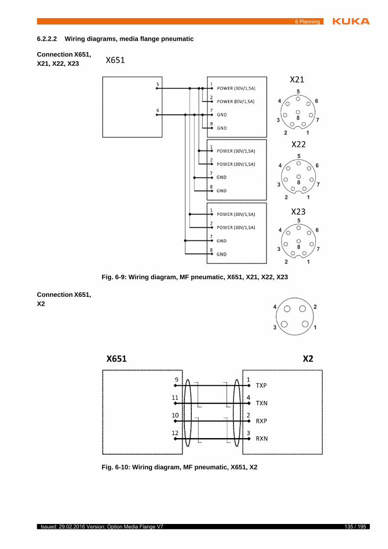
6 Planning
6.2.2.2 Wiring diagrams, media flange pneumatic
Connection X651,
X21, X22, X23
Connection X651,
X2
Fig. 6-9: Wiring diagram, MF pneumatic, X651, X21, X22, X23
Fig. 6-10: Wiring diagram, MF pneumatic, X651, X2
135 / 195Issued: 29.02.2016 Version: Option Media Flange V7

136 / 195
Media Flange
6.2.3 Media flange IO pneumatic
6.2.3.1 Interface, media flange IO pneumatic
Overview
Connection/
function
Fig. 6-11: Interface for media flange IO pneumatic
1 X2 EtherCat
2 X13 power supply, digital inputs/outputs
3 X12 power supply, digital inputs/outputs
4 Air 1 air connection
5 Air 2 air connection
6 X11 power supply, digital inputs/outputs
Connection Function
X2 EtherCAT, M8 connection, 4-pole
X11 Power supply
Digital inputs/outputs, M8 connection, 8-pole
X12 Power supply
Digital inputs/outputs, M8 connection, 8-pole
X13 Power supply
Digital inputs/outputs, M8 connection, 8-pole
Connection Designation Limit values
Air 1, air 2 Max. pressure 7 bar
Operating temperature +5 °C to +45 °C (278 K to 318 K)
condensation-free
Hose connection 4.0 mm Ø
Medium Air, oil-free, dry, filteredaccording to: ISO 8573.1-1, 1.2 to 16.2
Degree of filtration: max. 5 µm
Issued: 29.02.2016 Version: Option Media Flange V7

6 Planning
Digital outputs
Power supply
Digital inputs
Designation Values
Digital outputs 4
short-circuit proof
Rated voltage 24 V DC (-15%/+20%)
Output current max. 0.5 A per output
Short-circuit current max. 2 A
Load type Ohmic, inductive
Lamp load
Maximum cable length 1 m
Designation Values
Power supply 24 V DC (-15%/+20%) / 3 A
nominal 27 V
max. 1.5 A per pin
max. 2 A per socket
max. 3 A total
Maximum cable length 1 m
Designation Values
Digital inputs 8
Signal voltage “0” -3 V … +5 V
EN 61131-2, type 3
Signal voltage “1” 15 V … 30 V
EN 61131-2, type 3
Input current typically 3 mA
EN 61131-2, type 3
Input filter typically 0.3 ms
Maximum cable length 1 m
137 / 195Issued: 29.02.2016 Version: Option Media Flange V7
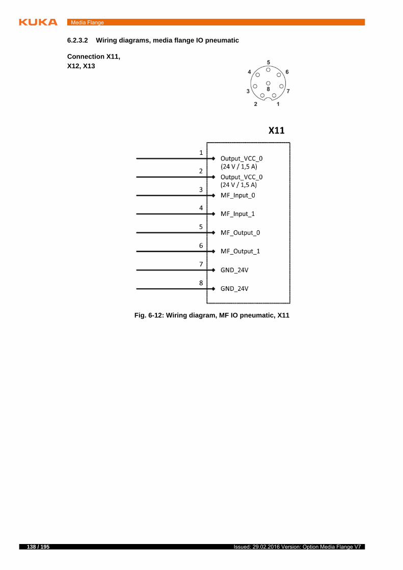
138 / 195
Media Flange
6.2.3.2 Wiring diagrams, media flange IO pneumatic
Connection X11,
X12, X13
Fig. 6-12: Wiring diagram, MF IO pneumatic, X11
Issued: 29.02.2016 Version: Option Media Flange V7

6 Planning
Fig. 6-13: Wiring diagram, MF IO pneumatic, X12
139 / 195Issued: 29.02.2016 Version: Option Media Flange V7

140 / 195
Media Flange
Connection X2
Fig. 6-14: Wiring diagram, MF IO pneumatic, X13
Fig. 6-15: Wiring diagram, connection X2
Issued: 29.02.2016 Version: Option Media Flange V7

6 Planning
6.2.4 Media flange Touch pneumatic
6.2.4.1 Interface, media flange Touch pneumatic
Overview
Connection/
function
Digital outputs
Fig. 6-16: Interface, media flange Touch pneumatic
1 Air 1 air connection
2 Air 2 air connection
3 X3 power supply, digital inputs/outputs
4 X2 EtherCat
Connection Function
X2 EtherCAT, M8 connection, 4-pole
X3 Power supply
Digital inputs/outputs, M12 connection, 17-pole
Connection Designation Limit values
Air 1, air 2 Max. pressure 7 bar
Operating temperature +5 °C to +45 °C (278 K to 318 K)
condensation-free
Hose connection 4.0 mm Ø
Medium Air, oil-free, dry, filteredaccording to: ISO 8573.1-1, 1.2 to 16.2
Degree of filtration: max. 5 µm
Designation Values
Digital outputs 4 digital outputs
short-circuit proof
Current monitoring for all 4 outputs together.
Switching states (rated voltage)
OFF (0): 0-1.5 V
ON (1): 11 V-30 V
Output current max. 0.5 A per output
Short-circuit current max. 2 A
141 / 195Issued: 29.02.2016 Version: Option Media Flange V7

142 / 195
Media Flange
Digital inputs
Power supply
EtherCAT
Load type Resistive: min. 56 ohms
Capacitive: max. 1 uF
Inductive: max. 400 mH
Note: For higher loads, the current limitation may be triggered or the switching times may be extended.
Maximum cable length 1 m
Designation Values
Designation Values
Digital inputs 5 digital inputs
Note: Debouncing is not carried out for any inputs.
Note: Inductive and capacitive loads are not per-missible.
Signal voltage “0” 0 V … +5 V
Note: If no signal is connected, the input takes the state “0”.
Signal voltage “1” 11 V … 30 V
Input current min. 5 mA with 27 V
Switching speed Application-specific, scanning of the input values every 25 ms
Maximum cable length 1 m
Designation Values
Power supply 24 V (±25%) / 3 A, switchable
nominal 27 V
Output SwitchOffX3Voltage
Logic 0: Power on
Logic 1: Power off
Default: 0
Note: The 4 Output_VCC and GND_24V pin pairs must be connected.
Note: Resupply of the media flange via the cus-tomer supply connections is not permissible.
Load type Resistive: min. 9 ohms
Capacitive: max. 1 uF
Inductive: max. 400 mH
Note: For higher loads, the current limitation may be triggered or the switching times may be extended.
Maximum cable length 1 m
Values Designation
Ethernet connection 100 Base-TX
Max. cable length EtherCAT
1 m
Issued: 29.02.2016 Version: Option Media Flange V7

6 Planning
6.2.4.2 Wiring diagrams, media flange Touch pneumatic
Connection X3
Fig. 6-17: Wiring diagram, connection X3
143 / 195Issued: 29.02.2016 Version: Option Media Flange V7

144 / 195
Media Flange
Connection X2
6.2.5 Media flange Touch electrical
6.2.5.1 Interface, media flange Touch pneumatic
Overview
Fig. 6-18: Wiring diagram, connection X2
Fig. 6-19: Interface, media flange Touch electrical
1 X74 interface for analog signals and CAT5 (external)
2 X75 power supply (external)
3 X3 power supply (internal), digital inputs/outputs
4 X2 EtherCat
Issued: 29.02.2016 Version: Option Media Flange V7

6 Planning
Connection/
function
Digital outputs
Digital inputs
Connection Function
X2 EtherCAT, M8 connection, 4-pole
X3 24 V power supply, internal
Digital inputs/outputs, M12 connection, 17-pole
X74 Interface for analog signals and CAT5
6x AWG 28 shielded, external via X76, M8 connec-tion, 3-pole
X75 Power supply
max. 60 V/4 A, externally via X76, M8 connection, 8-pole
Designation Values
Digital outputs 4 digital outputs
short-circuit proof
Current monitoring for all 4 outputs together.
Switching states (rated voltage)
OFF (0): 0-1.5 V
ON (1): 11 V-30 V
Output current max. 0.5 A per output
Short-circuit current max. 2 A
Load type Resistive: min. 56 ohms
Capacitive: max. 1 uF
Inductive: max. 400 mH
Note: For higher loads, the current limitation may be triggered or the switching times may be extended.
Maximum cable length 1 m
Designation Values
Digital inputs 5 digital inputs
Note: Debouncing is not carried out for any inputs.
Note: Inductive and capacitive loads are not per-missible.
Signal voltage “0” 0 V … +5 V
Note: If no signal is connected, the input takes the state “0”.
Signal voltage “1” 11 V … 30 V
Input current min. 5 mA with 27 V
Switching speed Application-specific, scanning of the input values every 25 ms
Maximum cable length 1 m
145 / 195Issued: 29.02.2016 Version: Option Media Flange V7

146 / 195
Media Flange
Power supply
EtherCAT
Designation Values
Power supply 24 V (±25%) / 3 A, switchable
nominal 27 V
Output SwitchOffX3Voltage
Logic 0: Power on
Logic 1: Power off
Default: 0
Note: The 4 Output_VCC and GND_24V pin pairs must be connected.
Note: Resupply of the media flange via the cus-tomer supply connections is not permissible.
Load type Resistive: min. 9 ohms
Capacitive: max. 1 uF
Inductive: max. 400 mH
Note: For higher loads, the current limitation may be triggered or the switching times may be extended.
Maximum cable length 1 m
Values Designation
Ethernet connection 100 Base-TX
Max. cable length EtherCAT
1 m
Issued: 29.02.2016 Version: Option Media Flange V7

6 Planning
6.2.5.2 Wiring diagrams, media flange Touch electrical
Connection X3
Fig. 6-20: Wiring diagram, connection X3
147 / 195Issued: 29.02.2016 Version: Option Media Flange V7
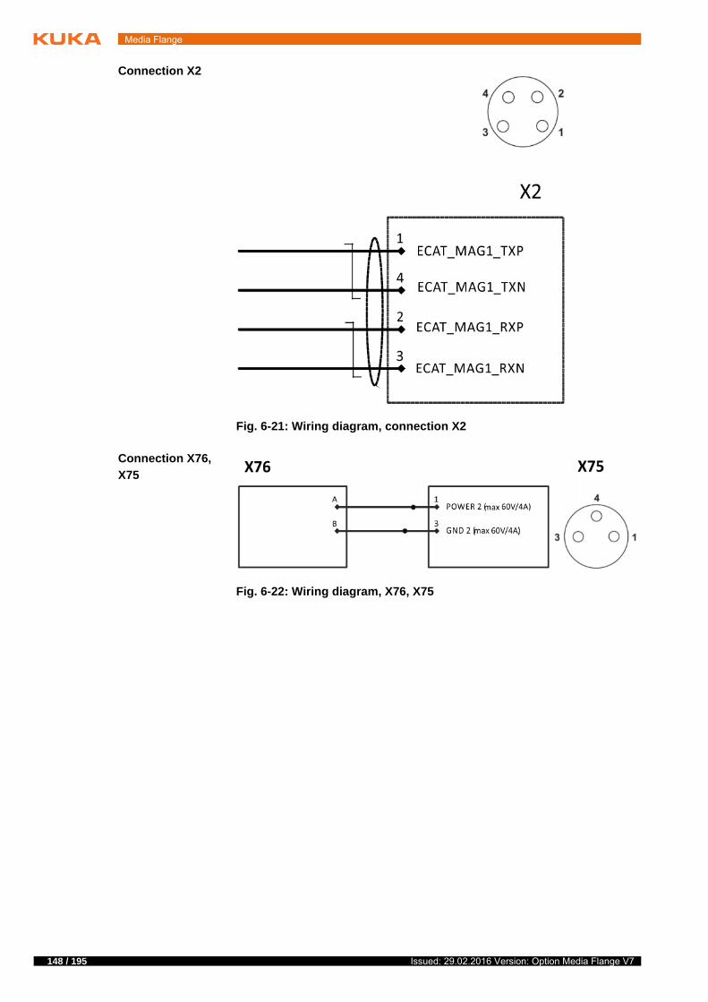
148 / 195
Media Flange
Connection X2
Connection X76,
X75
Fig. 6-21: Wiring diagram, connection X2
Fig. 6-22: Wiring diagram, X76, X75
Issued: 29.02.2016 Version: Option Media Flange V7

6 Planning
Connection X76,
X74
Fig. 6-23: Wiring diagram, connection X76, X74
149 / 195Issued: 29.02.2016 Version: Option Media Flange V7

150 / 195
Media Flange
6.2.6 Media flange IO electrical
6.2.6.1 Interface, media flange IO electrical
Overview
Connection/
function
Digital outputs
Fig. 6-24: Interface, media flange IO electrical
1 X2 EtherCat
2 X44 interface for analog signals and CAT5 (external)
3 X43 power supply, digital inputs/outputs
4 X42 power supply, digital inputs/outputs
5 X45 power supply (external)
6 X41 power supply, digital inputs/outputs
Connection Function
X2 EtherCAT, M8 connection, 4-pole
X41 24 V power supply, internal
Digital inputs/outputs, M8 connection, 8-pole
X42 24 V power supply, internal
Digital inputs/outputs, M8 connection, 8-pole
X43 24 V power supply, internal
Digital inputs/outputs, M8 connection, 8-pole
X44 Interface for analog signals and CAT5
6x AWG 28 shielded, external via X76, M8 connec-tion, 8-pole
X45 Power supply
max. 60 V/4 A, externally via X76, M8 connection, 8-pole
Designation Values
Digital outputs 4
short-circuit proof
Rated voltage 24 V DC (-15%/+20%)
Issued: 29.02.2016 Version: Option Media Flange V7

6 Planning
Power supply
Digital inputs
Output current max. 0.5 A per output
Short-circuit current max. 2 A
Load type Ohmic, inductive
Lamp load
Maximum cable length 1 m
Designation Values
Designation Values
Power supply 24 V DC (-15%/+20%) / 3 A
nominal 27 V
max. 1.5 A per pin
max. 2 A per socket
max. 3 A total
Maximum cable length 1 m
Designation Values
Digital inputs 8
Signal voltage “0” -3 V … +5 V
EN 61131-2, type 3
Signal voltage “1” 15 V … 30 V
EN 61131-2, type 3
Input current typically 3 mA
EN 61131-2, type 3
Input filter typically 0.3 ms
Maximum cable length 1 m
151 / 195Issued: 29.02.2016 Version: Option Media Flange V7

152 / 195
Media Flange
6.2.6.2 Wiring diagrams, media flange IO electrical
Connection X41
Fig. 6-25: Wiring diagram, connection X41
Issued: 29.02.2016 Version: Option Media Flange V7

6 Planning
Connection X42
Fig. 6-26: Wiring diagram, connection X42
153 / 195Issued: 29.02.2016 Version: Option Media Flange V7

154 / 195
Media Flange
Connection X43
Fig. 6-27: Wiring diagram, connection X43
Issued: 29.02.2016 Version: Option Media Flange V7

6 Planning
Connection X76,
X44
Connection X76,
X45
Fig. 6-28: Wiring diagram, connection X76, X44
Fig. 6-29: Wiring diagram, connection X76, X45
155 / 195Issued: 29.02.2016 Version: Option Media Flange V7

156 / 195
Media Flange
Connection X2
6.2.7 Media flange IO valve pneumatic
6.2.7.1 Interface, media flange IO valve pneumatic
Overview
Fig. 6-30: Wiring diagram, connection X2
Fig. 6-31: Interface, media flange IO valve pneumatic
1 X91 power supply, digital inputs/outputs
2 X92 power supply, digital inputs/outputs
3 X93 power supply, digital inputs/outputs
4 Silencer
5 Air connection valve
Issued: 29.02.2016 Version: Option Media Flange V7

6 Planning
Connection/
function
6 Air connection valve
7 Air line AIR 2
8 X2 EtherCat
Connection Function
X2 EtherCAT, M8 connection, 4-pole
X91 Power supply
Digital inputs/outputs, M8 connection, 8-pole
X92 Power supply
Digital inputs/outputs, M8 connection, 8-pole
X93 Power supply
Digital inputs/outputs, M8 connection, 8-pole
Connection Designation Limit values
Air 2 Min. pressure 0.95 bar
Max. pressure 7 bar
Operating temperature +5 °C to +45 °C (278 K to 318 K)
condensation-free
Hose connection 4.0 mm Ø
Medium Air, oil-free, dry, filteredaccording to: ISO 8573.1-1, 1.2 to 16.2
Degree of filtration: max. 5 µm
2.4 Min. pressure 3 bar
Max. pressure 7 bar
Operating temperature +5 °C to +45 °C (278 K to 318 K)
condensation-free
Hose connection 4.0 mm Ø
Medium Air, oil-free, dry, filteredaccording to: ISO 8573.1-1, 1.2 to 16.2
Degree of filtration: max. 5 µm
Operating time On: 30 ms ± 15%
On: 20 ms ± 15%
157 / 195Issued: 29.02.2016 Version: Option Media Flange V7

158 / 195
Media Flange
Schematic
diagram
Digital outputs
Power supply
Digital inputs
Fig. 6-32: Circuit diagram of pneumatic valves
Designation Values
Digital outputs 4
short-circuit proof
Rated voltage 24 V DC (-15%/+20%)
Output current max. 0.5 A per output
Short-circuit current max. 2 A
Load type Ohmic, inductive
Lamp load
Maximum cable length 1 m
Designation Values
Power supply 24 V DC (-15%/+20%) / 3 A
nominal 27 V
max. 1.5 A per pin
max. 2 A per socket
max. 3 A total
Maximum cable length 1 m
Designation Values
Digital inputs 8
Signal voltage “0” -3 V … +5 V
EN 61131-2, type 3
Signal voltage “1” 15 V … 30 V
EN 61131-2, type 3
Input current typically 3 mA
EN 61131-2, type 3
Input filter typically 0.3 ms
Maximum cable length 1 m
Issued: 29.02.2016 Version: Option Media Flange V7

6 Planning
6.2.7.2 Wiring diagrams, media flange IO valve pneumatic
Connection X91
Fig. 6-33: Wiring diagram, connection X91
159 / 195Issued: 29.02.2016 Version: Option Media Flange V7

160 / 195
Media Flange
Connection X92
Fig. 6-34: Wiring diagram, connection X92
Issued: 29.02.2016 Version: Option Media Flange V7

6 Planning
Connection X93
Connection X2
Fig. 6-35: Wiring diagram, connection X93
Fig. 6-36: Wiring diagram, connection X2
161 / 195Issued: 29.02.2016 Version: Option Media Flange V7

162 / 195
Media Flange
6.2.8 Media flange Inside electrical
6.2.8.1 Interface, media flange Inside electrical
Overview
Connection/
function
6.2.8.2 Wiring diagrams, media flange Inside electrical
Fig. 6-37: Interface, media flange Inside electrical
1 Tapped holes M2 for screw fastening of the tool connector to the flange
2 Connection panel for tool connector
Connection Function
Tool connector connection panel
CAT5 interface
4x AWG 26 shielded (CAT5), external via X651
Power supply
max. 60 V / 8 A external via X651
Power supply
max. 60 V / 5 A external via X76
Interface for analog signals and CAT5
6x AWG 28 shielded, external via X76
In order to be able to use the electrical interface of the media flange Inside electrical, electrical contact with the connection panel must be established using the tool connector.
If no tool is mounted on the media flange, the tool con-nector must be removed and the protective caps affixed
to the flange. Intervention into the interface of the flange may result in inju-ries.
Issued: 29.02.2016 Version: Option Media Flange V7

6 Planning
Connection X651,
tool connector
Connection X76,
tool connector
Fig. 6-38: Wiring diagram, MF Inside electrical, X651, tool connector
Fig. 6-39: Wiring diagram, MF Inside electrical, X76, tool connector
The tool connector may only be connected or discon-nected when deenergized. The media flange or the tool
connector may otherwise be damaged.
All exposed cables or cable ends of the tool connector must be insulated. This can lead to a short circuit and
thus to damage of the media flange.
163 / 195Issued: 29.02.2016 Version: Option Media Flange V7

164 / 195
Media Flange
6.2.9 Media flange Inside pneumatic
6.2.9.1 Interface, media flange Inside pneumatic
Overview
Connection/
function
Fig. 6-40: Interface, media flange Inside pneumatic
1 Air 1 air connection
2 Air 2 air connection
3 Connection panel for tool connector
4 Tapped holes M2 for screw fastening of the tool connector to the flange
Connection Function
Tool connector connection panel
Power supply
max. 60 V / 8 A external via X651
CAT5 interface
4x AWG 26 shielded (CAT5), external via X651
Connection Designation Limit values
Air 1, air 2 Max. pressure 7 bar
Operating temperature +5 °C to +45 °C (278 K to 318 K)
condensation-free
Hose connection 4.0 mm Ø
Medium Air, oil-free, dry, filteredaccording to: ISO 8573.1-1, 1.2 to 16.2
Degree of filtration: max. 5 µm
In order to be able to use the electrical interface of the media flange Inside electrical, electrical contact with the connection panel must be established using the tool connector.
Issued: 29.02.2016 Version: Option Media Flange V7

6 Planning
6.2.9.2 Wiring diagrams, media flange Inside pneumatic
Connection X651,
tool connector
6.2.10 Connector bypack X651
Description Two coding pins are included in the connector bypack. These are to be insert-ed as illustrated below.
If no tool is mounted on the media flange, the tool con-nector must be removed and the protective caps affixed
to the flange. Intervention into the interface of the flange may result in inju-ries.
Fig. 6-41: Wiring diagram, MF Inside pneumatic, X651, tool connector
The tool connector may only be connected or discon-nected when deenergized. The media flange or the tool
connector may otherwise be damaged.
All exposed cables or cable ends of the tool connector must be insulated. This can lead to a short circuit and
thus to damage of the media flange.
Fig. 6-42: Connector bypack X651
1 Coding pins
165 / 195Issued: 29.02.2016 Version: Option Media Flange V7

166 / 195
Media Flange
6.2.11 Data cable
Description The following points must be observed when planning and routing the con-necting cables:
The bending radius for fixed routing must not be less than 35 mm for data cables with power supply for media flange and 45 mm for data cables.
Protect cables against exposure to mechanical stress.
Route the cables without mechanical stress – no tensile forces on the con-nectors
Cables are only to be installed indoors.
Observe the permissible temperature range (fixed installation) of -10 °C to +70 °C (263 K to 343 K).
Route the motor cables and the control cables separately in metal ducts; if necessary, additional measures must be taken to ensure electromagnet-ic compatibility (EMC).
This data cable is required for operating the robot with the media flange IO pneumatic and media flange Touch pneumatic.
Fig. 6-43: Data cable X650, X651
Connecting the data cable to the robot with different me-dia flange types can result in damage to the components.
Issued: 29.02.2016 Version: Option Media Flange V7

6 Planning
6.2.12 Tool connector, media flange Inside electrical
Description In order to be able to use the electrical interface of the media flange Inside electrical and media flange Inside pneumatic, electrical contact with the con-nection panel must be established using the tool connector. The tool connec-tor can be installed on either the flange or the tool.
There are different ways to install the tool connector:
Installation on the flange using the supplied M2x16 screws
Installation on the tool
Connection/
function
The tool connector must be flush with the plane surface of the flange. Otherwise the electrical contact to the
flange cannot be ensured.The position and dimensions for installing the tool connector must be ob-served (>>> Fig. 6-45 ).
The recess in the tool for the outgoing cables must con-form to the cable bending radii. The minimum cable
bending radius is 5.85 mm. Suitable strain relief measures on the tool side must be implemented. The tool connector may otherwise be damaged.
Fig. 6-44: Tool connector, MF Inside electrical
1 Fastening screws M2x16 (4x)
2 Tool connector
3 Through-holes for installation of the tool on the flange (4x) or tool
Connection/func-
tionFunction
Connection for tool Tool connector with open breakout cable
Cable length approx. 44 cm
Signal/CAT5 cables
12x AWG26
Power cables 4x AWG18
Max. mating cycles 100
167 / 195Issued: 29.02.2016 Version: Option Media Flange V7

168 / 195
Media Flange
Dimensions
6.2.13 Tool connector, media flange Inside pneumatic
Description In order to be able to use the electrical interface of the media flange Inside electrical and media flange Inside pneumatic, electrical contact with the con-nection panel must be established using the tool connector. The tool connec-tor can be installed on either the flange or the tool.
There are different ways to install the tool connector:
Installation on the flange using the supplied M2x16 screws
Installation on the tool
Fig. 6-45: Dimensions, tool connector, top view
Fig. 6-46: Dimensions, tool connector, side view
Issued: 29.02.2016 Version: Option Media Flange V7

6 Planning
Connection/
function
The tool connector must be flush with the plane surface of the flange. Otherwise the electrical contact to the
flange cannot be ensured.The position and dimensions for the installation of the tool connector must be observed (>>> Fig. 6-48 ).
The recess in the tool for the outgoing cables must con-form to the cable bending radii. The minimum cable
bending radius (electrical) is 5.85 mm. Suitable strain relief measures on the tool side must be implemented. The tool connector may otherwise be dam-aged.
Fig. 6-47: Tool connector, MF Inside pneumatic
1 Fastening screws M2x16 (4x)
2 Tool connector
3 Through-holes for installation of the tool on the flange (4x) or tool
Connection/func-
tionFunction
Connection for tool Tool connector with open breakout cable
Cable length approx. 44 cm
Signal/CAT5 cables
4x AWG26
Power cables 2x AWG18
Max. mating cycles 100
169 / 195Issued: 29.02.2016 Version: Option Media Flange V7

170 / 195
Media Flange
Dimensions
Fig. 6-48: Dimensions, tool connector, top view
Fig. 6-49: Dimensions, tool connector, side view
Issued: 29.02.2016 Version: Option Media Flange V7

7 Transportation
7 Transportation
The media flange must not be transported without the robot.
T
s
t
t Further information about transporting the robot can be found in the operating or assembly instructions for the robot.
171 / 195Issued: 29.02.2016 Version: Option Media Flange V7

172 / 195
Media Flange
Issued: 29.02.2016 Version: Option Media Flange V7

8 Configuration
8 Configuration
8.1 Overview
Further information about configuration is provided in the following sections:
8.1.1 Media flange configuration
The media flange with which the robot is equipped must be selected when cre-ating the Sunrise project. The I/O configuration for the media flange is created automatically and contains the complete bus structure of the media flange, in-cluding the I/O mapping.
f
t
Media flange I/O Description
Media flange Touch pneumatic
Inputs: InputX3Pin3, InputX3Pin4, InputX3Pin10, InputX3Pin13, InputX3Pin16, Us-erButton (= application button)
Outputs: OutputX3Pin1, OutputX3Pin2, OutputX3Pin11, OutputX3Pin12, SwitchOffX3Voltage, LEDBlue (= light ring, blue)
(>>> 8.1.1 "Media flange configura-tion" Page 173)
Media flange IO pneumatic
Inputs: Input0…Input7
Outputs: Output0…Output3
(>>> 8.1.1 "Media flange configura-tion" Page 173)
Media flange Touch electrical
Inputs: InputX3Pin3, InputX3Pin4, InputX3Pin10, InputX3Pin13, InputX3Pin16, Us-erButton (= application button)
Outputs: OutputX3Pin1, OutputX3Pin2, OutputX3Pin11, OutputX3Pin12, SwitchOffX3Voltage, LEDBlue (= light ring, blue)
(>>> 8.1.1 "Media flange configura-tion" Page 173)
Media flange IO electrical
Inputs: Input0…Input7
Outputs: Output0…Output3
(>>> 8.1.1 "Media flange configura-tion" Page 173)
Media flange IO valve pneumatic
Inputs: Input0…Input7
Outputs: Output0…Output3, Valve1_ON, Valve1_OFF, Valve2_ON, Valve2_OFF
The pneumatic valves can be switched to bistable independently of one another using Valve1_ON, Valve1_OFF or Valve2_ON, Valve2_OFF. To change the state, the variable set originally must be reset to “false”.
(>>> 8.1.1 "Media flange configura-tion" Page 173)
The I/O configuration is created automatically for the media flange set in the project. If a media flange with an EtherCAT output (e.g. media flange IO pneumatic) is used and additional EtherCAT devices are
connected, these must be configured using WorkVisual.
173 / 195Issued: 29.02.2016 Version: Option Media Flange V7
174 / 195
Media Flange
The I/O group in which the inputs/outputs are configured is called Me-diaFlange. It contains inputs and outputs that are relevant for the correspond-ing media flange. The type and number of inputs and outputs the media flange has are found in the overview in the table (>>> 8.1 "Overview" Page 173).
The inputs/outputs can be addressed directly in the robot application. When the media flange is selected during creation of the Sunrise project, the class MediaFlangeIOGroup.java is generated at the same time. The class already contains the methods required for programming in order to access the inputs/outputs of the media flange.
When connecting additional EtherCAT devices to a media flange with an EtherCAT output, e.g. media flange IO pneumatic, it must be en-sured that the number of available signals on the bus is limited.
If there are too many connected devices, this can result in overloading of the bus and loss of communication. Under certain circumstances, the robot can then no longer be moved.
Detailed information about project creation is contained in the system software documentation.
Detailed information on device mapping is contained in the WorkVi-sual documentation.
Issued: 29.02.2016 Version: Option Media Flange V7
9 Maintenance
9 Maintenance
9.1 Maintenance
Description If used for its intended purpose, the media flange requires minimal mainte-nance, i.e. visual inspections are recommended. Regular visual inspections make sure that any changes are detected in good time. This enables early de-tection of damage, thereby preventing failure of components and assemblies. Damaged components or assemblies must be exchanged.
9.2 Cleaning
Precondition Power supply lead is disconnected.
Observe the EMC guidelines.
Work regulations The manufacturer’s instructions must be observed when using cleaning agents for cleaning work.
It must be ensured that no cleaning agents enter electrical components.
Do not use compressed air during cleaning work.
Do not spray with water.
Procedure 1. Loosen and vacuum up any dust deposits.
2. Clean the media flange with a cloth soaked with a mild cleaning agent.
3. Replace damaged, illegible or missing identifications, labels and plates.
t
Maintenance, cleaning and inspection measures must only be carried out by appropriately qualified and authorized personnel. All other maintenance, cleaning and inspection work not described in this doc-
umentation must only be carried out by KUKA Roboter GmbH.
Interval Activity
1 year Test the enabling switch
Information about testing the enabling switch is contained in the Sun-rise.OS documentation.
Further information on cleaning is contained in the robot documenta-tion.
175 / 195Issued: 29.02.2016 Version: Option Media Flange V7

176 / 195
Media Flange
Issued: 29.02.2016 Version: Option Media Flange V7

10 Repair
10 Repair
10.1 Repair
No repair work is planned for the media flanges. For further information, please contact your local KUKA Customer Support.
177 / 195Issued: 29.02.2016 Version: Option Media Flange V7

178 / 195
Media Flange
Issued: 29.02.2016 Version: Option Media Flange V7

11 Troubleshooting
11 Troubleshooting
11.1 Troubleshooting, media flange IO pneumatic, media flange Touch pneumatic
T
s
t Fault Cause Remedy
Short circuit Impermissible loads have been used.
The system automatically deactivates all outputs and automatically restarts after 5 s.
or
The system automatically disconnects the voltage supply and automatically restarts after 5 s.
179 / 195Issued: 29.02.2016 Version: Option Media Flange V7

180 / 195
Media Flange
Issued: 29.02.2016 Version: Option Media Flange V7

12 Decommissioning, storage and dispos...
12 Decommissioning, storage and disposal
12.1 Decommissioning
Decommissioning of the media flanges is carried out by KUKA Service.
12.2 Storage
Precondition If the media flanges are to be put into long-term storage, the following points must be observed:
To protect the contacts, the protective caps must be attached to the flange and the tool connector for the media flange Inside electric and media flange Inside pneumatic.
The place of storage must be as dry and dust-free as possible.
Avoid temperature fluctuations.
Avoid wind and drafts.
Avoid condensation.
Use appropriate coverings that cannot detach themselves and which can withstand the expected environmental conditions.
Do not leave any loose parts on the media adapter module, especially ones that might knock against other parts.
Do not leave media flanges exposed to direct sunlight while in storage.
Observe and comply with the permissible temperature ranges for storage.
Select a storage location in which the packaging materials cannot be dam-aged.
Procedure 1. Clean the media flange. No dirt may remain on the media flange.
2. Perform a visual inspection of the outside of the media flange.
3. Remove any foreign bodies.
4. Remove any corrosion expertly.
5. Unplug electrical connections and seal them with suitable covers.
6. Seal open inlets by suitable means.
7. Cover the media flange with plastic film and seal it against dust.
8. If necessary, add a desiccant beneath the sheeting.
12.3 Disposal
When the media flanges reach the end of their useful life, they can be removed from the system and dismantled, and the materials can be disposed of prop-erly by type.
The following table provides an overview of the materials used in the media flanges. All plastic components are marked with a material designation and must be disposed of accordingly.
2
s
s
Material, designationSubassembly, com-
ponentNote
Aluminum, steel Media flange
PUR Cable sheaths
Copper Cables, wires
PU Compressed air hoses
181 / 195Issued: 29.02.2016 Version: Option Media Flange V7

182 / 195
Media Flange
PA Connector housing
Electrical components Bus modules, valve terminals, sensors, connecting cables
Dispose of as electri-cal scrap without dis-assembling
Material, designationSubassembly, com-
ponentNote
Issued: 29.02.2016 Version: Option Media Flange V7

13 KUKA Service
13 KUKA Service
13.1 Requesting support
Introduction This documentation provides information on operation and operator control, and provides assistance with troubleshooting. For further assistance, please contact your local KUKA subsidiary.
Information The following information is required for processing a support request:
Description of the problem, including information about the duration and frequency of the fault
As comprehensive information as possible about the hardware and soft-ware components of the overall system
The following list gives an indication of the information which is relevant in many cases:
Model and serial number of the kinematic system, e.g. the manipulator
Model and serial number of the controller
Model and serial number of the energy supply system
Designation and version of the system software
Designations and versions of other software components or modifica-tions
Diagnostic package KrcDiag:
Additionally for KUKA Sunrise: Existing projects including applications
For versions of KUKA System Software older than V8: Archive of the software (KrcDiag is not yet available here.)
Application used
External axes used
13.2 KUKA Customer Support
Availability KUKA Customer Support is available in many countries. Please do not hesi-tate to contact us if you have any questions.
Argentina Ruben Costantini S.A. (Agency)
Luis Angel Huergo 13 20
Parque Industrial
2400 San Francisco (CBA)
Argentina
Tel. +54 3564 421033
Fax +54 3564 428877
Australia KUKA Robotics Australia Pty Ltd
45 Fennell Street
Port Melbourne VIC 3207
Australia
Tel. +61 3 9939 9656
www.kuka-robotics.com.au
A
v
183 / 195Issued: 29.02.2016 Version: Option Media Flange V7

184 / 195
Media Flange
Belgium KUKA Automatisering + Robots N.V.
Centrum Zuid 1031
3530 Houthalen
Belgium
Tel. +32 11 516160
Fax +32 11 526794
www.kuka.be
Brazil KUKA Roboter do Brasil Ltda.
Travessa Claudio Armando, nº 171
Bloco 5 - Galpões 51/52
Bairro Assunção
CEP 09861-7630 São Bernardo do Campo - SP
Brazil
Tel. +55 11 4942-8299
Fax +55 11 2201-7883
www.kuka-roboter.com.br
Chile Robotec S.A. (Agency)
Santiago de Chile
Chile
Tel. +56 2 331-5951
Fax +56 2 331-5952
www.robotec.cl
China KUKA Robotics China Co., Ltd.
No. 889 Kungang Road
Xiaokunshan Town
Songjiang District
201614 Shanghai
P. R. China
Tel. +86 21 5707 2688
Fax +86 21 5707 2603
www.kuka-robotics.com
Germany KUKA Roboter GmbH
Zugspitzstr. 140
86165 Augsburg
Germany
Tel. +49 821 797-4000
Fax +49 821 797-1616
www.kuka-roboter.de
Issued: 29.02.2016 Version: Option Media Flange V7

13 KUKA Service
France KUKA Automatisme + Robotique SAS
Techvallée
6, Avenue du Parc
91140 Villebon S/Yvette
France
Tel. +33 1 6931660-0
Fax +33 1 6931660-1
www.kuka.fr
India KUKA Robotics India Pvt. Ltd.
Office Number-7, German Centre,
Level 12, Building No. - 9B
DLF Cyber City Phase III
122 002 Gurgaon
Haryana
India
Tel. +91 124 4635774
Fax +91 124 4635773
www.kuka.in
Italy KUKA Roboter Italia S.p.A.
Via Pavia 9/a - int.6
10098 Rivoli (TO)
Italy
Tel. +39 011 959-5013
Fax +39 011 959-5141
www.kuka.it
Japan KUKA Robotics Japan K.K.
YBP Technical Center
134 Godo-cho, Hodogaya-ku
Yokohama, Kanagawa
240 0005
Japan
Tel. +81 45 744 7691
Fax +81 45 744 7696
Canada KUKA Robotics Canada Ltd.
6710 Maritz Drive - Unit 4
Mississauga
L5W 0A1
Ontario
Canada
Tel. +1 905 670-8600
Fax +1 905 670-8604
www.kuka-robotics.com/canada
185 / 195Issued: 29.02.2016 Version: Option Media Flange V7

186 / 195
Media Flange
Korea KUKA Robotics Korea Co. Ltd.
RIT Center 306, Gyeonggi Technopark
1271-11 Sa 3-dong, Sangnok-gu
Ansan City, Gyeonggi Do
426-901
Korea
Tel. +82 31 501-1451
Fax +82 31 501-1461
Malaysia KUKA Robot Automation (M) Sdn Bhd
South East Asia Regional Office
No. 7, Jalan TPP 6/6
Taman Perindustrian Puchong
47100 Puchong
Selangor
Malaysia
Tel. +60 (03) 8063-1792
Fax +60 (03) 8060-7386
Mexico KUKA de México S. de R.L. de C.V.
Progreso #8
Col. Centro Industrial Puente de Vigas
Tlalnepantla de Baz
54020 Estado de México
Mexico
Tel. +52 55 5203-8407
Fax +52 55 5203-8148
www.kuka-robotics.com/mexico
Norway KUKA Sveiseanlegg + Roboter
Sentrumsvegen 5
2867 Hov
Norway
Tel. +47 61 18 91 30
Fax +47 61 18 62 00
Austria KUKA Roboter CEE GmbH
Gruberstraße 2-4
4020 Linz
Austria
Tel. +43 7 32 78 47 52
Fax +43 7 32 79 38 80
www.kuka.at
Issued: 29.02.2016 Version: Option Media Flange V7

13 KUKA Service
Poland KUKA Roboter Austria GmbH
Spółka z ograniczoną odpowiedzialnością
Oddział w Polsce
Ul. Porcelanowa 10
40-246 Katowice
Poland
Tel. +48 327 30 32 13 or -14
Fax +48 327 30 32 26
Portugal KUKA Robots IBÉRICA, S.A.
Rua do Alto da Guerra n° 50
Armazém 04
2910 011 Setúbal
Portugal
Tel. +351 265 729 780
Fax +351 265 729 782
www.kuka.com
Russia KUKA Robotics RUS
Werbnaja ul. 8A
107143 Moskau
Russia
Tel. +7 495 781-31-20
Fax +7 495 781-31-19
www.kuka-robotics.ru
Sweden KUKA Svetsanläggningar + Robotar AB
A. Odhners gata 15
421 30 Västra Frölunda
Sweden
Tel. +46 31 7266-200
Fax +46 31 7266-201
Switzerland KUKA Roboter Schweiz AG
Industriestr. 9
5432 Neuenhof
Switzerland
Tel. +41 44 74490-90
Fax +41 44 74490-91
www.kuka-roboter.ch
187 / 195Issued: 29.02.2016 Version: Option Media Flange V7
188 / 195
Media Flange
Spain KUKA Robots IBÉRICA, S.A.
Pol. Industrial
Torrent de la Pastera
Carrer del Bages s/n
08800 Vilanova i la Geltrú (Barcelona)
Spain
Tel. +34 93 8142-353
Fax +34 93 8142-950
www.kuka.es
South Africa Jendamark Automation LTD (Agency)
76a York Road
North End
6000 Port Elizabeth
South Africa
Tel. +27 41 391 4700
Fax +27 41 373 3869
www.jendamark.co.za
Taiwan KUKA Robot Automation Taiwan Co., Ltd.
No. 249 Pujong Road
Jungli City, Taoyuan County 320
Taiwan, R. O. C.
Tel. +886 3 4331988
Fax +886 3 4331948
www.kuka.com.tw
Thailand KUKA Robot Automation (M)SdnBhd
Thailand Office
c/o Maccall System Co. Ltd.
49/9-10 Soi Kingkaew 30 Kingkaew Road
Tt. Rachatheva, A. Bangpli
Samutprakarn
10540 Thailand
Tel. +66 2 7502737
Fax +66 2 6612355
www.kuka-roboter.de
Czech Republic KUKA Roboter Austria GmbH
Organisation Tschechien und Slowakei
Sezemická 2757/2
193 00 Praha
Horní Počernice
Czech Republic
Tel. +420 22 62 12 27 2
Fax +420 22 62 12 27 0
Issued: 29.02.2016 Version: Option Media Flange V7
13 KUKA Service
Hungary KUKA Robotics Hungaria Kft.
Fö út 140
2335 Taksony
Hungary
Tel. +36 24 501609
Fax +36 24 477031
USA KUKA Robotics Corporation
51870 Shelby Parkway
Shelby Township
48315-1787
Michigan
USA
Tel. +1 866 873-5852
Fax +1 866 329-5852
www.kukarobotics.com
UK KUKA Robotics UK Ltd
Great Western Street
Wednesbury West Midlands
WS10 7LL
UK
Tel. +44 121 505 9970
Fax +44 121 505 6589
www.kuka-robotics.co.uk
189 / 195Issued: 29.02.2016 Version: Option Media Flange V7

190 / 195
Media Flange
Issued: 29.02.2016 Version: Option Media Flange V7

Index
Index
Numbers2004/108/EC 1252006/42/EC 1252014/30/EC 12595/16/EC 125
AAir humidity 26, 32, 38, 44, 50, 56, 62, 68, 75, 81Ambient conditions 26, 32, 38, 44, 50, 56, 62, 68, 75, 81Ambient temperature, operation 26, 32, 38, 44, 50, 56, 62, 68, 75, 81Ambient temperature, storage 26, 32, 38, 44, 50, 56, 62, 68, 75, 81Ambient temperature, transportation 26, 32, 38, 44, 50, 56, 62, 68, 75, 81Angle of rotation 87ANSI/RIA R.15.06-2012 126Applied norms and regulations 125
BBasic data, basic flange 25Basic data, media flange electrical 31Basic data, media flange Inside electrical 74Basic data, media flange Inside pneumatic 80Basic data, media flange IO electrical 62Basic data, media flange IO pneumatic 43Basic data, media flange IO valve pneumatic 68Basic data, media flange pneumatic 37Basic data, media flange Touch electrical 56Basic data, media flange Touch pneumatic 49
CCleaning 175Configuration 173Configuration, media flange 173Connector bypack X651 165
DDecommissioning 181Dimensions, basic flange 26Dimensions, media flange electrical 32Dimensions, media flange Inside electrical 75Dimensions, media flange Inside pneumatic 81Dimensions, media flange IO electrical 62Dimensions, media flange IO pneumatic 44Dimensions, media flange IO valve pneumatic 69Dimensions, media flange pneumatic 38Dimensions, media flange Touch electrical 56Dimensions, media flange Touch pneumatic 50Disposal 181Documentation, options 7DTM 7
EElectromagnetic compatibility (EMC) 126EMC Directive 125
EMC resistance 25, 31, 37, 44, 50, 56, 62, 68, 74, 80EN 60204-1 + A1 126EN 61000-6-2 126EN 61000-6-4 + A1 126EN 614-1 + A1 126EN 62061 + A1 126EN ISO 10218-1 126EN ISO 12100 125EN ISO 13849-1 125EN ISO 13849-2 125EN ISO 13850 125EtherCAT 7
GGeneral information 86
IIdentification plate, basic flange 26Identification plate, MF electrical 32Identification plate, MF Inside electrical 75Identification plate, MF Inside pneumatic 81Identification plate, MF IO electrical 63Identification plate, MF IO pneumatic 44Identification plate, MF IO valve pneumatic 69Identification plate, MF pneumatic 38Identification plate, MF Touch electrical 57Identification plate, MF Touch pneumatic 50Intended use 9Interface, media flange electrical 130Interface, media flange Inside electrical 162Interface, media flange Inside pneumatic 164Interface, media flange IO electrical 150Interface, media flange IO pneumatic 136Interface, media flange IO valve pneumatic 156Interface, media flange pneumatic 134Interface, media flange Touch pneumatic 141, 144Interfaces on A1 127Introduction 7
KKCP, KUKA Control Panel 87KUKA Customer Support 183
MMachinery Directive 125Maintenance 175Material designation 181Media flange electrical 130Media flange Inside electrical 162Media flange Inside pneumatic 164Media flange interfaces, overview 128Media flange IO pneumatic 136Media flange pneumatic 134MF 7
191 / 195Issued: 29.02.2016 Version: Option Media Flange V7

192 / 195
Media Flange
OOverview, media flange 11
PPayloads, basic flange 27Payloads, media flange electrical 33Payloads, media flange Inside electrical 76Payloads, media flange Inside pneumatic 82Payloads, media flange IO electrical 63Payloads, media flange IO pneumatic 45Payloads, media flange IO valve pneumatic 69Payloads, media flange pneumatic 39Payloads, media flange Touch electrical 57Payloads, media flange Touch pneumatic 51Planning 127Product description 11Product description, basic flange 11Product description, media flange electrical 12Product description, media flange Inside electrical 18Product description, media flange Inside pneumatic 18Product description, media flange IO electrical 16Product description, media flange IO pneumatic 13Product description, media flange IO valve pneumatic 17Product description, media flange pneumatic 12Product description, media flange Touch electrical 15Product description, media flange Touch pneumatic 13Program override, motion velocity 87Purpose 9
RRepair 177
SSafety 125Safety instructions 7Safety of machinery 125, 126Safety, option 125Service, KUKA Roboter GmbH 183STOP 0 87STOP 1 87Stop signal 86Stopping distance 86Stopping distances 86Stopping distances for LBR iiwa 14 R820 97, 115Stopping distances for LBR iiwa 7 R800 89, 106Stopping distances for STOP 0, axis 1 to axis 4 89, 98, 107, 116Stopping distances for STOP 1, axis 1 90, 99, 108, 117Stopping distances for STOP 1, axis 2 92, 101, 110, 119Stopping distances for STOP 1, axis 3 94, 103, 112, 121Stopping distances for STOP 1, axis 4 96, 105,
114, 123Stopping time 87Stopping times 86Stopping times for LBR iiwa 14 R820 97, 115Stopping times for LBR iiwa 7 R800 89, 106Stopping times for STOP 0, axis 1 to axis 4 89, 98, 107, 116Stopping times for STOP 1, axis 1 90, 99, 108, 117Stopping times for STOP 1, axis 2 92, 101, 110, 119Stopping times for STOP 1, axis 3 94, 103, 112, 121Stopping times for STOP 1, axis 4 96, 105, 114, 123Storage 181Supplementary load 30, 36, 42, 48, 54, 60, 66, 72, 79, 85Support request 183
TTechnical data 21Technical data, basic flange 25Technical data, media flange electrical 31Technical data, media flange Inside electrical 74Technical data, media flange Inside pneumatic 80Technical data, media flange IO electrical 62Technical data, media flange IO pneumatic 43Technical data, media flange IO valve pneumatic 68Technical data, media flange pneumatic 37Technical data, media flange Touch electrical 56Technical data, media flange Touch pneumatic 49Technical data, overview 21Terms 7Terms used 87Tool connector, media flange Inside electrical 167Tool connector, media flange Inside pneumatic 168Trademarks 8Training 9Transportation 171Troubleshooting 179
UUsers 9
WWarnings 7Wiring diagrams, media flange electrical 131Wiring diagrams, media flange Inside electrical 162Wiring diagrams, media flange Inside pneumatic 165Wiring diagrams, media flange IO electrical 152Wiring diagrams, media flange IO pneumatic 138Wiring diagrams, media flange IO valve pneumatic 159
Issued: 29.02.2016 Version: Option Media Flange V7

Index
Wiring diagrams, media flange pneumatic 135Wiring diagrams, media flange Touch electrical 147Wiring diagrams, media flange Touch pneumatic 143Working envelope, basic flange 30Working envelope, media flange electrical 36Working envelope, media flange Inside electrical 79Working envelope, media flange Inside pneumatic 85Working envelope, media flange IO electrical 66Working envelope, media flange IO pneumatic 48Working envelope, media flange IO valve pneumatic 72Working envelope, media flange pneumatic 42Working envelope, media flange Touch electrical 60Working envelope, media flange Touch pneumatic 54
193 / 195Issued: 29.02.2016 Version: Option Media Flange V7

194 / 195
Media Flange
Issued: 29.02.2016 Version: Option Media Flange V7

195 / 195Issued: 29.02.2016 Version: Option Media Flange V7
Media Flange