mediant™ 800 msbr - audiocodes · throughout this manual, unless otherwise specified, the term...
TRANSCRIPT
Hardware Installation Manual AudioCodes Series of Multi-Service Business Routers (MSBR)
Mediant™ 800 MSBR

MSBR Series 3 MSBR Series
Hardware Installation Manual Contents
Table of Contents 1 Introduction ....................................................................................................... 11
2 Unpacking the Device ...................................................................................... 13
3 Physical Description ........................................................................................ 15
3.1 Physical Dimensions .............................................................................................. 15 3.2 Front Panel Description .......................................................................................... 15
3.2.1 Ports and Buttons.................................................................................................... 15 3.2.2 LEDs ....................................................................................................................... 18
3.2.2.1 LAN Interface LED ................................................................................... 18 3.2.2.2 Power-over-Ethernet LAN LED ............................................................... 18 3.2.2.3 Wi-Fi LED ................................................................................................ 19 3.2.2.4 WAN LEDs ............................................................................................... 19 3.2.2.5 FXS LED .................................................................................................. 21 3.2.2.6 FXO LED ................................................................................................. 21 3.2.2.7 BRI LED ................................................................................................... 22 3.2.2.8 PRI (E1/T1) LED ...................................................................................... 22 3.2.2.9 STATUS LED ........................................................................................... 22 3.2.2.10 Power LEDs ............................................................................................. 23
3.3 Rear Panel Description .......................................................................................... 24
4 Attaching the Wi-Fi Antennas .......................................................................... 27
5 Mounting the Device ........................................................................................ 29
5.1 Desktop Mounting .................................................................................................. 29 5.2 19-Inch Rack Mounting .......................................................................................... 30
5.2.1 Using a Pre-Installed Rack Shelf ............................................................................ 30 5.2.2 Using Mounting Brackets ........................................................................................ 31
6 Cabling the Device ........................................................................................... 33
6.1 Grounding and Surge Protection ............................................................................ 33 6.2 Connecting to WAN ................................................................................................ 35
6.2.1 Copper Gigabit Ethernet (GE) Cabling ................................................................... 35 6.2.2 Fiber-Optic Gigabit Ethernet Cabling ...................................................................... 36 6.2.3 SHDSL WAN Cabling ............................................................................................. 38 6.2.4 ADSL/2+ and VDSL2 WAN Cabling ....................................................................... 40 6.2.5 E1/T1 WAN Cabling ................................................................................................ 42 6.2.6 3G/3.5G Cellular WAN USB Modem Cabling ......................................................... 44
6.3 Connecting to LAN ................................................................................................. 45 6.4 Connecting PoE-Enabled Clients to LAN Ports ...................................................... 46 6.5 Analog Interfaces ................................................................................................... 47
6.5.1 Connecting FXS Interfaces ..................................................................................... 47 6.5.2 Connecting FXO interfaces ..................................................................................... 48 6.5.3 Connecting the FXS Analog Lifeline ....................................................................... 50
6.6 ISDN BRI Interfaces ............................................................................................... 51 6.6.1 Connecting to BRI Lines ......................................................................................... 51 6.6.2 Connecting the PSTN Fallback for BRI Lines ......................................................... 53
6.7 Connecting to ISDN PRI (E1/T1) Trunks ................................................................ 54 6.8 Connecting the Serial Interface to a PC ................................................................. 56 6.9 Connecting a USB Storage Device ........................................................................ 58 6.10 Connecting the OSN Server ................................................................................... 59

Hardware Installation Manual 4 Document #: LTRT-10245
Mediant 800 MSBR
6.11 Connecting to Power .............................................................................................. 61 6.11.1 Connecting to AC Power ......................................................................................... 61 6.11.2 Connecting to DC Power ........................................................................................ 62
7 Maintenance ...................................................................................................... 65
7.1 Replacing the Power Fuse ..................................................................................... 65
A Approved Laser SFPs ...................................................................................... 67
B Notice for Installing CentOS Version 4.7 on OSN Server .............................. 69

MSBR Series 5 MSBR Series
Hardware Installation Manual Contents
List of Figures Figure 3-1: Front Panel - Mediant 800B MSBR ..................................................................................... 15 Figure 3-2: Front Panel - Mediant 800C MSBR ..................................................................................... 16 Figure 3-3: Rear Panel - Mediant 800B MSBR ..................................................................................... 24 Figure 3-4: Rear Panel - Mediant 800C MSBR ..................................................................................... 24 Figure 4-1: Attaching Antennas on Rear Panel ..................................................................................... 27 Figure 5-1: Location for Applying Rubber Feet ...................................................................................... 29 Figure 5-2: Mounting Brackets ............................................................................................................... 31 Figure 5-3: Attaching the Mounting Brackets ........................................................................................ 31 Figure 6-1: Earthing the Device ............................................................................................................. 34 Figure 6-2: Cabling WAN Copper GE Port – Mediant 800B MSBR ...................................................... 36 Figure 6-3: Cabling WAN Copper GE Port – Mediant 800C MSBR ...................................................... 36 Figure 6-4: Removing Protective Dust Plug – Mediant 800B MSBR ..................................................... 37 Figure 6-5: Removing Protective Dust Plug – Mediant 800C MSBR .................................................... 37 Figure 6-6: Cabling Fiber-Optic WAN GbE Port – Mediant 800B MSBR .............................................. 38 Figure 6-7: Cabling Fiber-Optic WAN GbE Port – Mediant 800C MSBR .............................................. 38 Figure 6-8: Cabling the SHDSL WAN Port ............................................................................................ 39 Figure 6-9: Cabling xDSL WAN Port – Mediant 800B MSBR ............................................................... 41 Figure 6-10: Cabling xDSL WAN Port – Mediant 800C MSBR ............................................................. 42 Figure 6-11: RJ-45 Connector Pinouts for E1/T1 WAN ......................................................................... 42 Figure 6-12: Splitter Cable for Single E1/T1 WAN Port ......................................................................... 43 Figure 6-13: Connecting E1/T1 WAN Port – Mediant 800B MSBR ....................................................... 43 Figure 6-14: Connecting T1 WAN Port – Mediant 800C MSBR ............................................................ 43 Figure 6-15: Plugging 3G Cellular Modem into USB Port – Mediant 800B MSBR ............................... 44 Figure 6-16: Plugging 3G Cellular Modem into USB Port – Mediant 800C MSBR ............................... 44 Figure 6-17: Cabling LAN Ports – Mediant 800B MSBR ....................................................................... 45 Figure 6-18: Cabling LAN Ports – Mediant 800C MSBR ....................................................................... 46 Figure 6-19: RJ-11 Connector Pinouts for FXS Interface ...................................................................... 47 Figure 6-20: Connecting FXS Interfaces – Mediant 800B MSBR ......................................................... 48 Figure 6-21: Connecting FXS Interfaces – Mediant 800C MSBR ......................................................... 48 Figure 6-22: RJ-11 Connector Pinouts for FXO Interface ..................................................................... 49 Figure 6-23: Connecting FXO Interfaces ............................................................................................... 49 Figure 6-24: RJ-11 Connector Pinouts for FXS Lifeline ........................................................................ 50 Figure 6-25: Cabling FXS Lifeline – Mediant 800B MSBR .................................................................... 50 Figure 6-26: Cabling FXS Lifeline – Mediant 800C MSBR .................................................................... 51 Figure 6-27: RJ-45 Connector Pinouts for BRI Ports ............................................................................ 51 Figure 6-28: Cabling BRI Ports – Mediant 800B MSBR ........................................................................ 52 Figure 6-29: Cabling BRI Ports – Mediant 800C MSBR ........................................................................ 52 Figure 6-30: Cabling BRI PSTN Fallback – Mediant 800B MSBR ........................................................ 53 Figure 6-31: Cabling BRI PSTN Fallback – Mediant 800C MSBR ........................................................ 54 Figure 6-32: RJ-48c Connector Pinouts for E1/T1 ................................................................................ 54 Figure 6-33: Cabling E1/T1 Ports – Mediant 800B MSBR .................................................................... 55 Figure 6-34: Cabling E1/T1 Ports – Mediant 800C MSBR .................................................................... 55 Figure 6-35: RS-232 Cable Adapter ...................................................................................................... 56 Figure 6-36: Cabling Serial Interface - Mediant 800B MSBR ................................................................ 57 Figure 6-37: Cabling Serial Interface - Mediant 800C MSBR ................................................................ 57 Figure 6-38: Connecting USB Storage Device – Mediant 800B MSBR ................................................ 58 Figure 6-39: Connecting USB Storage Device – Mediant 800C MSBR ................................................ 58 Figure 6-40: Cabling OSN Server Ports ................................................................................................ 60 Figure 6-41: Connecting to the Power Supply ....................................................................................... 62 Figure 6-42: Connecting DC Power Plug to DC Inlet ............................................................................ 63 Figure 6-43: Plugging AC Power Cord into AC/DC Adaptor ................................................................. 64 Figure 7-1: Opening the Fuse Cavity ..................................................................................................... 65 Figure 7-2: Removing the Power Fuse .................................................................................................. 65
Hardware Installation Manual 6 Document #: LTRT-10245
Mediant 800 MSBR
List of Tables Table 3-1: Physical Dimensions ............................................................................................................ 15 Table 3-2: Front-Panel Description of Ports and Buttons ...................................................................... 16 Table 3-3: LAN LED Description ............................................................................................................ 18 Table 3-4: PoE LAN LED Description .................................................................................................... 18 Table 3-5: Wi-Fi LED Description .......................................................................................................... 19 Table 3-6: GE WAN LED Description .................................................................................................... 19 Table 3-7: E1/T1 WAN LED Description................................................................................................ 19 Table 3-8: SHDSL WAN LED Description ............................................................................................. 20 Table 3-9: A/VDSL WAN LED Description ............................................................................................ 20 Table 3-10: WAN SFP LED Description ................................................................................................ 21 Table 3-11: FXS LED Description .......................................................................................................... 21 Table 3-12: FXO LED Description ......................................................................................................... 21 Table 3-13: BRI LED Description ........................................................................................................... 22 Table 3-14: E1/T1 LED Description ....................................................................................................... 22 Table 3-15: STATUS LED Description .................................................................................................. 22 Table 3-16: POWER LED Description ................................................................................................... 23 Table 3-17: AC PWR LED Description .................................................................................................. 23 Table 3-18: DC PWR LED Description .................................................................................................. 23 Table 3-19: Rear Panel Description ....................................................................................................... 24 Table 6-1: RJ-45 Connector Pinouts for Copper GE WAN.................................................................... 35 Table 6-2: RJ-11 Connector Pinouts for SHDSL ................................................................................... 39 Table 6-3: RJ-11 Connector Pinouts for xDSL ...................................................................................... 40 Table 6-4: RJ-45 Connector Pinouts for xDSL ...................................................................................... 41 Table 6-5: RJ-45 Connector Pinouts for GbE/FE with PoE ................................................................... 45 Table 6-6: RJ-45 to DB-9 Serial Cable Connector Pinouts ................................................................... 56 Table 6-7: OSN Server Platforms .......................................................................................................... 59 Table 6-8: AC Power Specifications ...................................................................................................... 61 Table 6-9: DC Power Specifications ...................................................................................................... 62 Table 7-1: Allowed Fuses for the Device ............................................................................................... 65 Table A-1: Approved SFP Modules ....................................................................................................... 67
MSBR Series 7 MSBR Series
Hardware Installation Manual Notices
Notice Information contained in this document is believed to be accurate and reliable at the time of printing. However, due to ongoing product improvements and revisions, AudioCodes cannot guarantee accuracy of printed material after the Date Published nor can it accept responsibility for errors or omissions. Updates to this document can be downloaded from https://www.audiocodes.com/library/technical-documents.
This document is subject to change without notice.
Date Published: January-21-2019
WEEE EU Directive Pursuant to the WEEE EU Directive, electronic and electrical waste must not be disposed of with unsorted waste. Please contact your local recycling authority for disposal of this product.
Customer Support Customer technical support and services are provided by AudioCodes or by an authorized AudioCodes Service Partner. For more information on how to buy technical support for AudioCodes products and for contact information, please visit our website at https://www.audiocodes.com/services-support/maintenance-and-support.
Stay in the Loop with AudioCodes
Abbreviations and Terminology Each abbreviation, unless widely used, is spelled out in full when first used. Throughout this manual, unless otherwise specified, the term device refers to Mediant 800 MSBR.
Related Documentation
Document Name
SIP Release Notes
Mediant 800 MSBR SIP User's Manual
CLI Reference Guide
Hardware Installation Manual 8 Document #: LTRT-10245
Mediant 800 MSBR
Notes and Warnings
Warning: The device is an INDOOR unit and therefore, must be installed only indoors.
Note: Open source software may have been added and/or amended for this product. For further information, please visit our website at https://www.audiocodes.com/services-support/open-source/ or contact your AudioCodes sales representative.
Caution Electrical Shock Do not open or disassemble this device. The device carries high voltage and contact with internal components may expose you to electrical shock and bodily harm.
Warning: The device must be installed and serviced only by qualified service personnel.
Warning: For deployment in Finland, Sweden and Norway, the device must be installed ONLY in restricted access locations that are compliant with ETS 300253 guidelines here equipotential bonding has been implemented.
Warning: Disconnect the device from the mains and Telephone Network Voltage (TNV) before servicing.
MSBR Series 9 MSBR Series
Hardware Installation Manual Notices
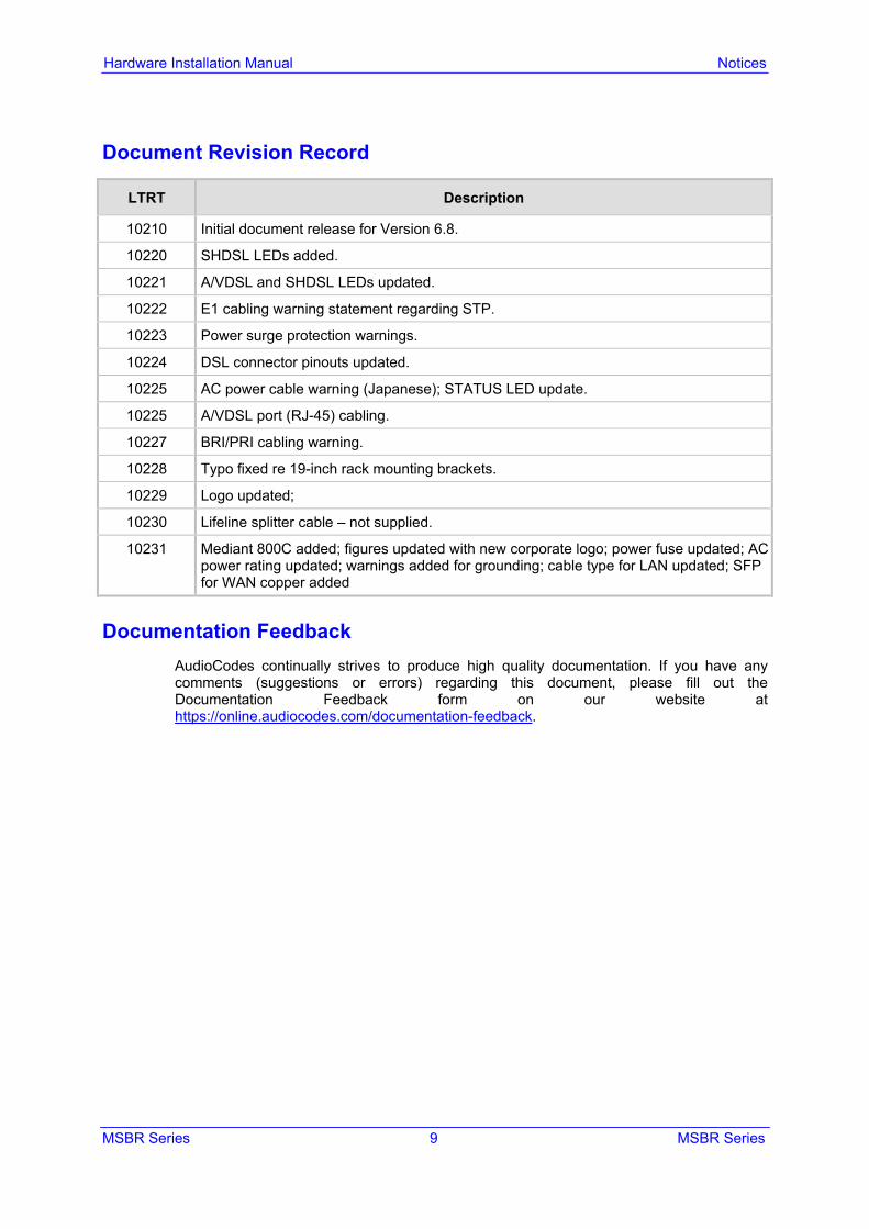
Document Revision Record
LTRT Description
10210 Initial document release for Version 6.8.
10220 SHDSL LEDs added.
10221 A/VDSL and SHDSL LEDs updated.
10222 E1 cabling warning statement regarding STP.
10223 Power surge protection warnings.
10224 DSL connector pinouts updated.
10225 AC power cable warning (Japanese); STATUS LED update.
10225 A/VDSL port (RJ-45) cabling.
10227 BRI/PRI cabling warning.
10228 Typo fixed re 19-inch rack mounting brackets.
10229 Logo updated;
10230 Lifeline splitter cable – not supplied.
10231 Mediant 800C added; figures updated with new corporate logo; power fuse updated; AC power rating updated; warnings added for grounding; cable type for LAN updated; SFP for WAN copper added
Documentation Feedback AudioCodes continually strives to produce high quality documentation. If you have any comments (suggestions or errors) regarding this document, please fill out the Documentation Feedback form on our website at https://online.audiocodes.com/documentation-feedback.

Hardware Installation Manual 10 Document #: LTRT-10245
Mediant 800 MSBR
This page is intentionally left blank.
MSBR Series 11 MSBR Series
Hardware Installation Manual 1. Introduction
1 Introduction This document provides a hardware description of the Mediant 800 MSBR (hereafter referred to as device) and step-by-step procedures for mounting and cabling the device. The device provides the following interfaces: Optional telephony interfaces:
• E1/T1: ♦ Mediant 800B MSBR: Up to 2 E1/T1 port interfaces (over single copper wire
pair). ♦ Mediant 800C MSBR: Up to 4 E1/T1 port interfaces
• Up to 8 BRI ports (supporting up to 16 voice channels) • Up to 12 FXS ports • FXS Lifeline on FXS Port 1, maintaining PSTN connectivity upon power failure.
For the combined FXS/FXO configuration, one Lifeline is available; for the 12-FXS configuration, up to three Lifelines are available.
• (Mediant 800B MSBR Only) Up to 12 FXO ports Optional LAN interfaces:
• Up to 12 Ethernet LAN ports: ♦ Up to 4 RJ-45 10/100/1000Base-T (Gigabit) ports ♦ Up to 8 RJ-45 10/100Base-TX (Fast Ethernet) ports Power over Ethernet (PoE) is supported on all LAN ports, complying with IEEE 802.3af-2003 and EEE 802.3at-2003. Various power budgets are supported for PoE on the LAN ports.
• (Mediant 800B MSBR Only) Wireless LAN 802.11n (Wi-Fi) access point at 2.4 GHz and 5 GHz Tx / Rx, enabling data rates of up to 300 Mbps. The Wi-Fi interface also supports 802.11b/802.11g backward compatibility, allowing interoperability of multiple devices with different types of Wi-Fi.
Two USB ports for an optional, 3G cellular WAN modem and/or USB storage services Integrated Gigabit Ethernet (GE) Unshielded Twisted Pair (UTP) interface port, with an
option of one or two additional WAN interfaces of the following types (factory assembled option): • GE UTP • (Mediant 800B MSBR Only) Up to 4 E1/T1 WAN • (Mediant 800C MSBR Only) 1 x T1 WAN • 1.25 Gbps Optical Fiber SFP form factor • ADSL2+ / VDSL2 • (Mediant 800B MSBR Only) SHDSL, supporting up to four wire-pairs • 1 x Ethernet copper WAN port (10/100/1000Base-T) • 3G Cellular WAN access (primary or backup) using a USB modem
RJ-45 serial interface port Open Solutions Network (OSN) server platform for hosting third-party applications
such as an IP PBX. Power:
• Mediant 800B MSBR: Single AC power inlet • Mediant 800C MSBR: Single AC power inlet, and a DC power inlet (optional,
customer ordered)
Hardware Installation Manual 12 Document #: LTRT-10245
Mediant 800 MSBR
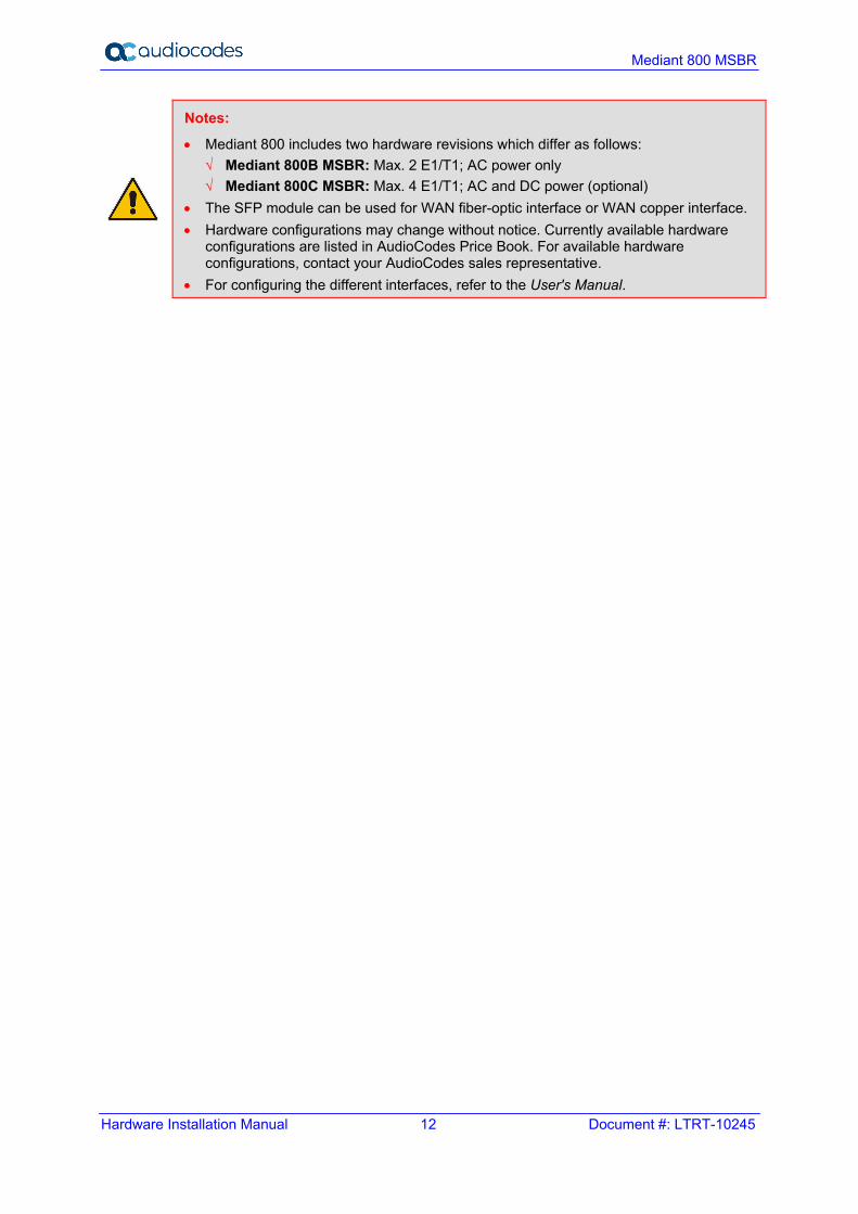
Notes:
• Mediant 800 includes two hardware revisions which differ as follows: √ Mediant 800B MSBR: Max. 2 E1/T1; AC power only √ Mediant 800C MSBR: Max. 4 E1/T1; AC and DC power (optional)
• The SFP module can be used for WAN fiber-optic interface or WAN copper interface. • Hardware configurations may change without notice. Currently available hardware
configurations are listed in AudioCodes Price Book. For available hardware configurations, contact your AudioCodes sales representative.
• For configuring the different interfaces, refer to the User's Manual.
MSBR Series 13 MSBR Series
Hardware Installation Manual 2. Unpacking the Device
2 Unpacking the Device Follow the procedure below for unpacking the carton in which the device was shipped.
To unpack the device: 1. Open the carton and carefully remove packing materials. 2. Remove the chassis from the carton. 3. Check that there is no equipment damage. 4. Ensure that in addition to the chassis, the package contains the following items:
• Four anti-slide bumpers for desktop installation • Two mounting brackets for 19-inch rack mounting • (Mediant 800C MSBR Only) Three Wi-Fi antennas (depending on ordered
model) • One E1/T1 splitter cable adapter (RJ-45 male to two RJ-45 female shielded) for
E1/T1 WAN interface (only if device is ordered with a single E1/T1 WAN port) • Serial cable adapter • One AC power cable • (Mediant 800C MSBR Only) one AC/DC power adaptor (optional, separate
orderable item) 5. Check, retain and process any documents. If there are any damaged or missing items, notify your AudioCodes sales representative.

Hardware Installation Manual 14 Document #: LTRT-10245
Mediant 800 MSBR
This page is intentionally left blank.

MSBR Series 15 MSBR Series
Hardware Installation Manual 3. Physical Description
3 Physical Description This section provides a physical description of the device.
3.1 Physical Dimensions The device's physical dimensions and weight are listed in the table below:
Table 3-1: Physical Dimensions
Physical Specification Value
Dimensions (W x D x H) 32 x 34.5 cm (12.6 x 13.6 inches) x 1U
Weight 2.5 kg (5.5 lb)
Environmental Operational: 5 to 40°C (41 to 104°F) Storage: -25 to 85°C (-13 to 185°F) Humidity: 10 to 90% non-condensing
3.2 Front Panel Description The front panel provides the telephony port interfaces, various networking ports, reset pinhole button, and LEDs.
3.2.1 Ports and Buttons The device's front panel is shown in the figure below and described in the subsequent table.
Figure 3-1: Front Panel - Mediant 800B MSBR

Hardware Installation Manual 16 Document #: LTRT-10245
Mediant 800 MSBR
Figure 3-2: Front Panel - Mediant 800C MSBR
Notes: • The figures above are used only as examples; the number and type of port interfaces
depends on the ordered model. • For available hardware configurations, please contact your AudioCodes sales
representative.
Table 3-2: Front-Panel Description of Ports and Buttons
Item # Label Description
1 Mediant 800B MSBR: POWER / STATUS / Wi-Fi
Mediant 800C MSBR: AC PWR / DC PWR /
STATUS
Power, operating and Wi-Fi status LEDs. For more information, see Section 3.2.2 on page 18. Note: The Wi-Fi LED is applicable only to Mediant 800B MSBR (if ordered with Wi-Fi functionality).
2 FXS / FXO / BRI / PRI (Optional) Telephony port interfaces, which can include one or a combination of the following, depending on ordered model: • FXS port interfaces (RJ-11) • FXO port interfaces (RJ-11) • ISDN BRI port interfaces (RJ-45) • ISDN PRI (E1/T1) port interfaces (RJ-48) Note: The FXS/FXO interfaces support loop-start signalling
(indoor only). FXO is applicable only to Mediant 800B MSBR.
3 // Reset pinhole button for resetting the device and optionally, for restoring the device to factory defaults. To restore the device to factory defaults, do the following: With a paper clip or any other similar pointed object, press and hold down the pinhole button for at least 12 seconds, but no longer than 25 seconds.
4 GE (Copper GbE) / V/ADSLoPOTS / DSLoISDN
/ DSLoPOTS / SHDSL /
GE SFP (Optic Fiber) /
(Optional) One or two additional WAN interfaces (copper GE, SFP, SHDSL, A/VDSL, and E1/T1 WAN). For a list of supported WAN configurations, please contact your AudioCodes sales representative. Note: SHDSL and E1 WAN are applicable only to Mediant 800B MSBR.
MSBR Series 17 MSBR Series
Hardware Installation Manual 3. Physical Description
Item # Label Description
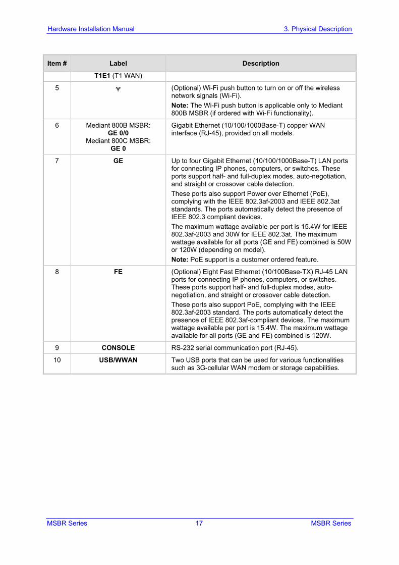
T1E1 (T1 WAN)
5 (Optional) Wi-Fi push button to turn on or off the wireless network signals (Wi-Fi). Note: The Wi-Fi push button is applicable only to Mediant 800B MSBR (if ordered with Wi-Fi functionality).
6 Mediant 800B MSBR: GE 0/0
Mediant 800C MSBR: GE 0
Gigabit Ethernet (10/100/1000Base-T) copper WAN interface (RJ-45), provided on all models.
7 GE Up to four Gigabit Ethernet (10/100/1000Base-T) LAN ports for connecting IP phones, computers, or switches. These ports support half- and full-duplex modes, auto-negotiation, and straight or crossover cable detection. These ports also support Power over Ethernet (PoE), complying with the IEEE 802.3af-2003 and IEEE 802.3at standards. The ports automatically detect the presence of IEEE 802.3 compliant devices. The maximum wattage available per port is 15.4W for IEEE 802.3af-2003 and 30W for IEEE 802.3at. The maximum wattage available for all ports (GE and FE) combined is 50W or 120W (depending on model). Note: PoE support is a customer ordered feature.
8 FE (Optional) Eight Fast Ethernet (10/100Base-TX) RJ-45 LAN ports for connecting IP phones, computers, or switches. These ports support half- and full-duplex modes, auto-negotiation, and straight or crossover cable detection. These ports also support PoE, complying with the IEEE 802.3af-2003 standard. The ports automatically detect the presence of IEEE 802.3af-compliant devices. The maximum wattage available per port is 15.4W. The maximum wattage available for all ports (GE and FE) combined is 120W.
9 CONSOLE RS-232 serial communication port (RJ-45).
10 USB/WWAN Two USB ports that can be used for various functionalities such as 3G-cellular WAN modem or storage capabilities.
Hardware Installation Manual 18 Document #: LTRT-10245
Mediant 800 MSBR
3.2.2 LEDs The front panel provides various LEDs depending on the device's hardware configuration (e.g., the available telephony interfaces). These LEDs are described in the subsequent subsections.
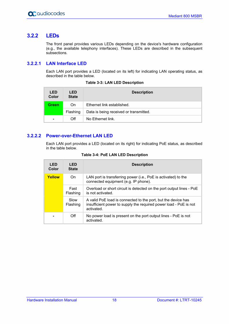
3.2.2.1 LAN Interface LED Each LAN port provides a LED (located on its left) for indicating LAN operating status, as described in the table below.
Table 3-3: LAN LED Description
LED Color
LED State
Description
Green On Ethernet link established.
Flashing Data is being received or transmitted.
- Off No Ethernet link.
3.2.2.2 Power-over-Ethernet LAN LED Each LAN port provides a LED (located on its right) for indicating PoE status, as described in the table below.
Table 3-4: PoE LAN LED Description
LED Color
LED State
Description
Yellow On LAN port is transferring power (i.e., PoE is activated) to the connected equipment (e.g. IP phone).
Fast Flashing
Overload or short circuit is detected on the port output lines - PoE is not activated.
Slow Flashing
A valid PoE load is connected to the port, but the device has insufficient power to supply the required power load - PoE is not activated.
- Off No power load is present on the port output lines - PoE is not activated.
MSBR Series 19 MSBR Series
Hardware Installation Manual 3. Physical Description
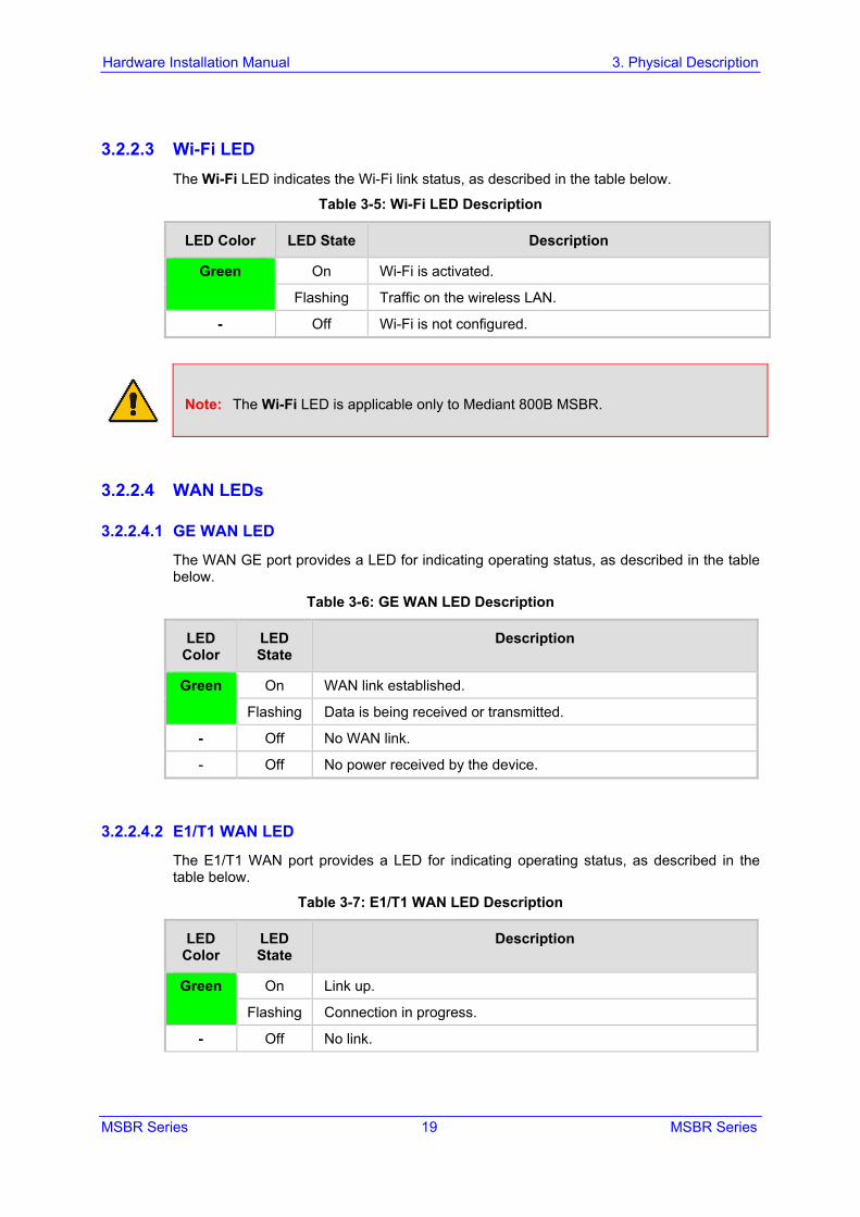
3.2.2.3 Wi-Fi LED The Wi-Fi LED indicates the Wi-Fi link status, as described in the table below.
Table 3-5: Wi-Fi LED Description
LED Color LED State Description
Green On Wi-Fi is activated.
Flashing Traffic on the wireless LAN.
- Off Wi-Fi is not configured.
Note: The Wi-Fi LED is applicable only to Mediant 800B MSBR.
3.2.2.4 WAN LEDs
3.2.2.4.1 GE WAN LED
The WAN GE port provides a LED for indicating operating status, as described in the table below.
Table 3-6: GE WAN LED Description
LED Color
LED State
Description
Green On WAN link established.
Flashing Data is being received or transmitted.
- Off No WAN link.
- Off No power received by the device.
3.2.2.4.2 E1/T1 WAN LED
The E1/T1 WAN port provides a LED for indicating operating status, as described in the table below.
Table 3-7: E1/T1 WAN LED Description
LED Color
LED State
Description
Green On Link up.
Flashing Connection in progress.
- Off No link.
Hardware Installation Manual 20 Document #: LTRT-10245
Mediant 800 MSBR
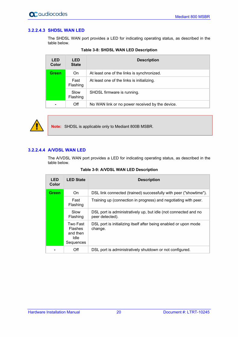
3.2.2.4.3 SHDSL WAN LED
The SHDSL WAN port provides a LED for indicating operating status, as described in the table below.
Table 3-8: SHDSL WAN LED Description
LED Color
LED State
Description
Green On At least one of the links is synchronized.
Fast Flashing
At least one of the links is initializing.
Slow Flashing
SHDSL firmware is running.
- Off No WAN link or no power received by the device.
Note: SHDSL is applicable only to Mediant 800B MSBR.
3.2.2.4.4 A/VDSL WAN LED
The A/VDSL WAN port provides a LED for indicating operating status, as described in the table below.
Table 3-9: A/VDSL WAN LED Description
LED Color
LED State Description
Green On DSL link connected (trained) successfully with peer ("showtime").
Fast Flashing
Training up (connection in progress) and negotiating with peer.
Slow Flashing
DSL port is administratively up, but idle (not connected and no peer detected).
Two Fast Flashes and then
Idle Sequences
DSL port is initializing itself after being enabled or upon mode change.
- Off DSL port is administratively shutdown or not configured.

MSBR Series 21 MSBR Series
Hardware Installation Manual 3. Physical Description
3.2.2.4.5 SFP WAN LED
The WAN SFP LED indicates the status of the optical fiber WAN link, as described in the table below.
Table 3-10: WAN SFP LED Description
LED Color
LED State
Description
Green On WAN fiber link established.
Flashing Data is being received or transmitted.
- Off No WAN fiber link or power not received by the device.
3.2.2.5 FXS LED Each FXS port provides a LED for indicating operating status, as described in the table below.
Table 3-11: FXS LED Description
LED Color
LED State
Description
Green On Phone is off-hooked.
Flashing Rings the extension line.
Red On Error - malfunction in line or out of service due to Serial Peripheral Interface (SPI) failure
Disabled port initiated by user (using the CLI command, analog-port-enable)
- Off Phone is on hook.
- Off No power received by the device.
3.2.2.6 FXO LED Each FXO port provides a LED for indicating operating status, as described in the table below.
Table 3-12: FXO LED Description
LED Color
LED State
Description
Green On FXO line is off-hooked toward the PBX.
Flashing Ring signal detected from the PBX.
Red On Error - malfunction in line or out of service due to Serial Peripheral Interface (SPI) failure
Disabled port initiated by user (using the CLI command, analog-port-enable)
- Off Line is on hook.
- Off No power received by the device.

Hardware Installation Manual 22 Document #: LTRT-10245
Mediant 800 MSBR
Note: The FXO LEDs are applicable only to Mediant 800B MSBR.
3.2.2.7 BRI LED Each BRI port provides a LED for indicating operating status, as described in the table below:
Table 3-13: BRI LED Description
Color State Description
Green On Physical layer (Layer 1) is synchronized (normal operation).
Red On Physical layer (Layer 1) is not synchronized.
- Off Trunk is not active.
3.2.2.8 PRI (E1/T1) LED Each trunk port provides a LED for indicating operating status, as described in the table below:
Table 3-14: E1/T1 LED Description
Color State Description
Green On Trunk is synchronized (normal operation).
Red On Loss due to any of the following signals: LOS - Loss of Signal LOF - Loss of Frame AIS - Alarm Indication Signal (the Blue Alarm) RAI - Remote Alarm Indication (the Yellow Alarm)
- Off Failure / disruption in the AC power supply or the power is currently not being supplied to the device through the AC power supply entry.
3.2.2.9 STATUS LED The STATUS LED indicates the operating status, as described in the table below.
Table 3-15: STATUS LED Description
LED Color
LED State
Description
Green On Device is operational.
Flashing Initial rebooting stage. Software upgrade (.cmp file) in process (currently supported
only from Software Version 6.8).
Red On Boot failure.
- Off Advanced rebooting stage.
MSBR Series 23 MSBR Series
Hardware Installation Manual 3. Physical Description
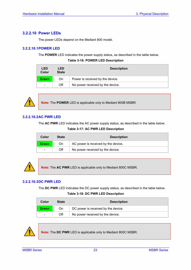
3.2.2.10 Power LEDs The power LEDs depend on the Mediant 800 model.
3.2.2.10.1 POWER LED
The POWER LED indicates the power supply status, as described in the table below.
Table 3-16: POWER LED Description
LED Color
LED State
Description
Green On Power is received by the device.
- Off No power received by the device.
Note: The POWER LED is applicable only to Mediant 800B MSBR.
3.2.2.10.2 AC PWR LED
The AC PWR LED indicates the AC power supply status, as described in the table below.
Table 3-17: AC PWR LED Description
Color State Description
Green On AC power is received by the device.
- Off No power received by the device.
Note: The AC PWR LED is applicable only to Mediant 800C MSBR.
3.2.2.10.3 DC PWR LED
The DC PWR LED indicates the DC power supply status, as described in the table below.
Table 3-18: DC PWR LED Description
Color State Description
Green On DC power is received by the device.
- Off No power received by the device.
Note: The DC PWR LED is applicable only to Mediant 800C MSBR.
Hardware Installation Manual 24 Document #: LTRT-10245
Mediant 800 MSBR
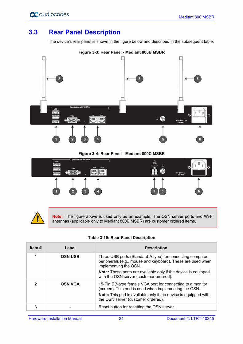
3.3 Rear Panel Description The device's rear panel is shown in the figure below and described in the subsequent table.
Figure 3-3: Rear Panel - Mediant 800B MSBR
Figure 3-4: Rear Panel - Mediant 800C MSBR
Note: The figure above is used only as an example. The OSN server ports and Wi-Fi antennas (applicable only to Mediant 800B MSBR) are customer ordered items.
Table 3-19: Rear Panel Description
Item # Label Description
1 OSN USB Three USB ports (Standard-A type) for connecting computer peripherals (e.g., mouse and keyboard). These are used when implementing the OSN. Note: These ports are available only if the device is equipped with the OSN server (customer ordered).
2 OSN VGA 15-Pin DB-type female VGA port for connecting to a monitor (screen). This port is used when implementing the OSN. Note: This port is available only if the device is equipped with the OSN server (customer ordered).
3 - Reset button for resetting the OSN server.
MSBR Series 25 MSBR Series
Hardware Installation Manual 3. Physical Description
Item # Label Description
4 GE 1 GE 2
10/100/1000Base-T Ethernet ports (RJ-45) for connecting directly to the OSN server. For example, one port can be connected to the LAN (to IP Phones) and the second port to the WAN interface (to an IP PBX). Note: The number of ports depends on ordered OSN server platform (see Section 6.10 on page 59).
5
Protective earthing screw.
6 Mediant 800B MSBR: 100-240V~1.5A
50-60Hz Mediant 800C MSBR:
100-240V~2.5A 50-60Hz
3-Prong AC power supply entry.
7 DC IN 12V-10A DC power inlet for accepting a DC terminal block plug. Note: DC power is applicable only to Mediant 800C MSBR. Use only the AC/DC power adaptor that is supplied by
AudioCodes to connect the DC inlet.
8 - Wi-Fi antennas, providing wireless LAN 802.11n (Wi-Fi) access point at 2.4 GHz and 5 GHz Tx / Rx, enabling data rates of up to 300 Mbps. The Wi-Fi interface also supports 802.11b/802.11g backward compatibility, allowing interoperability of multiple devices with different types of Wi-Fi. Note: The Wi-Fi antennas are applicable only to Mediant 800B MSBR (only if Wi-Fi functionality is ordered). They are shipped un-attached.

Hardware Installation Manual 26 Document #: LTRT-10245
Mediant 800 MSBR
This page is intentionally left blank.

MSBR Series 27 MSBR Series
Hardware Installation Manual 4. Attaching the Wi-Fi Antennas
4 Attaching the Wi-Fi Antennas For models ordered with wireless LAN interface, the device is shipped with three unattached Wi-Fi antennas. You can attach any number of these antennas, according to your network requirements. Once attached, you can position each antenna in the vertical and/or horizontal plane for optimal transmission and reception.
Notes:
• Wi-Fi interface is applicable only to Mediant 800B MSBR and is a customer ordered item.
• Attach antennas before mounting the device. It may be difficult to attach the antennas once the device is mounted.
To attach the Wi-Fi antennas to the device: 1. Manually screw the antennas on to the SMA coaxial RF connector located on the rear
panel, as shown in the figure below:
Figure 4-1: Attaching Antennas on Rear Panel
2. Orient the antennas as desired for optimal wireless performance. The antenna can be
orientated in the vertical and horizontal planes. For best performance, it is recommended that the antennas be perpendicular (90 degrees) to the floor. In other words, orient the antennas straight up.

Hardware Installation Manual 28 Document #: LTRT-10245
Mediant 800 MSBR
This page is intentionally left blank.
MSBR Series 29 MSBR Series
Hardware Installation Manual 5. Mounting the Device
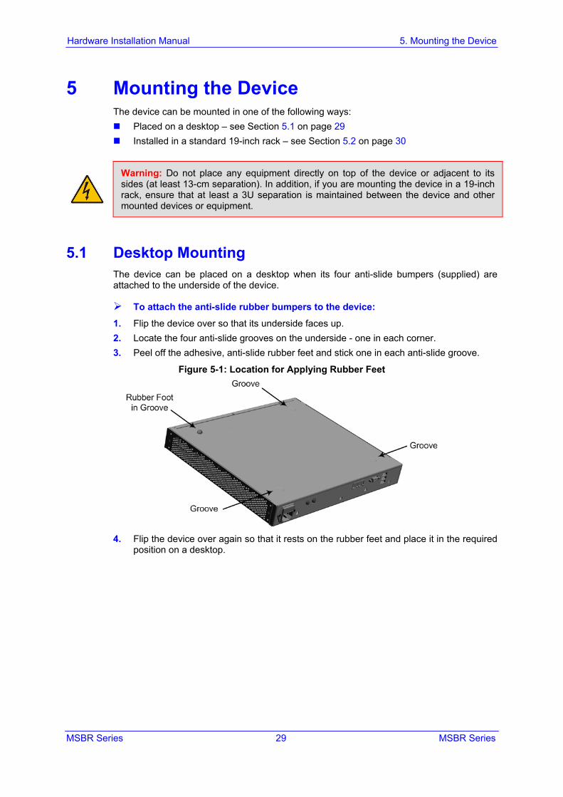
5 Mounting the Device The device can be mounted in one of the following ways: Placed on a desktop – see Section 5.1 on page 29 Installed in a standard 19-inch rack – see Section 5.2 on page 30
Warning: Do not place any equipment directly on top of the device or adjacent to its sides (at least 13-cm separation). In addition, if you are mounting the device in a 19-inch rack, ensure that at least a 3U separation is maintained between the device and other mounted devices or equipment.
5.1 Desktop Mounting The device can be placed on a desktop when its four anti-slide bumpers (supplied) are attached to the underside of the device.
To attach the anti-slide rubber bumpers to the device: 1. Flip the device over so that its underside faces up. 2. Locate the four anti-slide grooves on the underside - one in each corner. 3. Peel off the adhesive, anti-slide rubber feet and stick one in each anti-slide groove.
Figure 5-1: Location for Applying Rubber Feet
4. Flip the device over again so that it rests on the rubber feet and place it in the required
position on a desktop.
Hardware Installation Manual 30 Document #: LTRT-10245
Mediant 800 MSBR
5.2 19-Inch Rack Mounting The device can be installed in a standard 19-inch rack by implementing one of the following mounting methods: Placing it on a pre-installed shelf in a 19-inch rack – see Section 5.2.1 on page 30 Attaching it directly to the rack’s frame using the device's mounting brackets (supplied)
that need to be attached to the chassis – see Section 5.2.2 on page 31
Rack Mount Safety Instructions
When installing the chassis in a rack, implement the following safety instructions: • Elevated Operating Ambient Temperature: If installed in a closed or multi-unit rack
assembly, the operating ambient temperature of the rack environment may be greater than room ambient temperature. Therefore, consideration should be given to installing the equipment in an environment with maximum ambient temperature (Tma) of 40°C (104°F).
• Reduced Air Flow: Installation of the equipment in a rack should be such that the amount of air flow required for safe operation on the equipment is not compromised.
• Mechanical Loading: Mounting of the equipment in the rack should be such that a hazardous condition is not achieved due to uneven mechanical loading.
• Circuit Overloading: Consideration should be given to the connection of the equipment to the supply circuit and the effect that overloading of the circuits might have on over-current protection and supply wiring. Appropriate consideration of equipment nameplate ratings should be used when addressing this concern.
• Reliable Earthing: Reliable earthing of rack-mounted equipment should be maintained. Particular attention should be given to supply connections other than direct connections to the branch circuit (e.g., use of power strips). For earthing the device, see Section 6.1 on page 33.
5.2.1 Using a Pre-Installed Rack Shelf The procedure below describes how to place the device on a pre-installed shelf in a 19-inch rack.
To mount the device on a pre-installed shelf in the rack: 1. Before installing it in the rack, ensure that you have a pre-installed rack shelf on which
the device can be placed. 2. Place the device on the pre-installed shelf in the rack.
MSBR Series 31 MSBR Series
Hardware Installation Manual 5. Mounting the Device
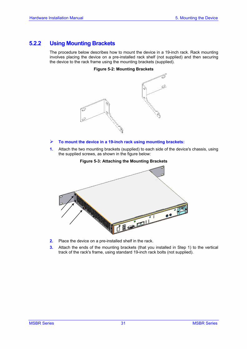
5.2.2 Using Mounting Brackets The procedure below describes how to mount the device in a 19-inch rack. Rack mounting involves placing the device on a pre-installed rack shelf (not supplied) and then securing the device to the rack frame using the mounting brackets (supplied).
Figure 5-2: Mounting Brackets
To mount the device in a 19-inch rack using mounting brackets: 1. Attach the two mounting brackets (supplied) to each side of the device's chassis, using
the supplied screws, as shown in the figure below:
Figure 5-3: Attaching the Mounting Brackets
2. Place the device on a pre-installed shelf in the rack. 3. Attach the ends of the mounting brackets (that you installed in Step 1) to the vertical
track of the rack's frame, using standard 19-inch rack bolts (not supplied).

Hardware Installation Manual 32 Document #: LTRT-10245
Mediant 800 MSBR
This page is intentionally left blank.
MSBR Series 33 MSBR Series
Hardware Installation Manual 6. Cabling the Device
6 Cabling the Device This section describes the cabling of the device.
6.1 Grounding and Surge Protection The device must be connected to earth (grounded) using an equipment-earthing conductor.
Protective Earthing The equipment is classified as Class I EN60950 and UL60950 and must be earthed at all times. For Finland: "Laite on liltettava suojamaadoituskoskettimilla varustettuun pistorasiaan." For Norway: "Apparatet rna tilkoples jordet stikkontakt." For Sweden: "Apparaten skall anslutas till jordat uttag."
Grounding and Power Surge Protection • The device must be installed only in telecommunication sites / centers in compliance
with ETS 300-253 requirements "Earthing and Bonding of Telecommunication Equipment in Telecommunication Centers".
• Prior to installation, earth loop impedance test must be performed by a certified electrician to ensure grounding suitability at the power outlet intended to feed the unit. It is essential that the impedance will be kept below 0.5 ohms!
• Proper grounding is crucial to ensure the effectiveness of the lightning protection, connect the device permanently to ground (as described in the procedure below). The device's grounding screw must be connected to the equipotential grounding bus bar located in the Telecommunication rack or installation site, using a wire of 6 mm2 surface wire. If the device is installed in a rack with other equipment, the rack must be connected to the equipotential grounding bus bar of the Telecommunication room, using a stranded cable with surface area of 25 mm2. The length of this cable must be as short as possible (no longer than 3 meters).
• The device does not include primary telecom protection! When the FXO / DSL telephone lines are routed outside the building, additional protection - usually a 350V three-electrode Gas Discharge Tube (GDT) as described in ITU-T K.44 - must be provided at the entry point of the telecom wires into the building (usually on the main distribution frame / MDF), in conjunction with proper grounding. The center pin of the GDT (MDF grounding bar) must be connected to the equipotential grounding bus bar of the Telecommunication room.
• Failing to install primary surge protectors and failing to comply with the grounding instructions or any other installation instructions, may cause permanent damage to the device!
• As most of the installation is the responsibility of the customer, AudioCodes can assume responsibility for damage only if the customer can establish that the device does not comply with the standards specified above (and the device is within the hardware warranty period).
• The device complies with protection levels as required by EN 55024/EN 300386. Higher levels of surges may cause damage to the device.
• To protect against electrical shock and fire, use a minimum of 26-AWG wire size to connect the FXO / DSL ports.
Hardware Installation Manual 34 Document #: LTRT-10245
Mediant 800 MSBR
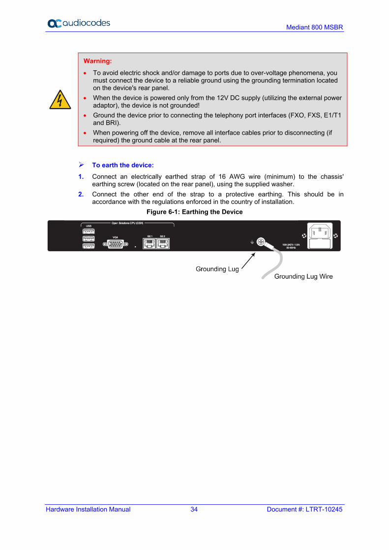
Warning:
• To avoid electric shock and/or damage to ports due to over-voltage phenomena, you must connect the device to a reliable ground using the grounding termination located on the device's rear panel.
• When the device is powered only from the 12V DC supply (utilizing the external power adaptor), the device is not grounded!
• Ground the device prior to connecting the telephony port interfaces (FXO, FXS, E1/T1 and BRI).
• When powering off the device, remove all interface cables prior to disconnecting (if required) the ground cable at the rear panel.
To earth the device: 1. Connect an electrically earthed strap of 16 AWG wire (minimum) to the chassis'
earthing screw (located on the rear panel), using the supplied washer. 2. Connect the other end of the strap to a protective earthing. This should be in
accordance with the regulations enforced in the country of installation. Figure 6-1: Earthing the Device
MSBR Series 35 MSBR Series
Hardware Installation Manual 6. Cabling the Device
6.2 Connecting to WAN This section provides a description on how to cable the WAN port. The cabling procedure depends on the ordered WAN interface.
Note: The device supports multiple WAN redundancies, where multiple WAN interfaces can serve as backups for the primary or a backup WAN interface. For example, if the main WAN interface is GE and it fails, the device switches over to the SHDSL WAN interface. If this WAN interface also fails, the device switches over to the 3G WAN interface, and so on. For configuring WAN redundancy, refer to the CLI Reference Guide.
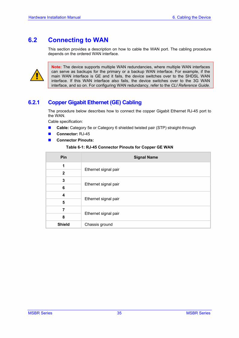
6.2.1 Copper Gigabit Ethernet (GE) Cabling The procedure below describes how to connect the copper Gigabit Ethernet RJ-45 port to the WAN. Cable specification: Cable: Category 5e or Category 6 shielded twisted pair (STP) straight-through Connector: RJ-45 Connector Pinouts:
Table 6-1: RJ-45 Connector Pinouts for Copper GE WAN
Pin Signal Name
1 Ethernet signal pair
2
3 Ethernet signal pair
6
4 Ethernet signal pair
5
7 Ethernet signal pair
8
Shield Chassis ground
Hardware Installation Manual 36 Document #: LTRT-10245
Mediant 800 MSBR
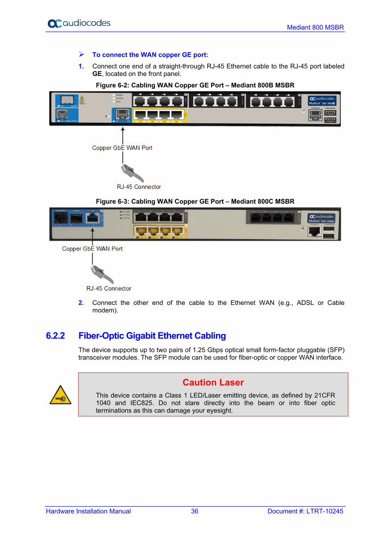
To connect the WAN copper GE port: 1. Connect one end of a straight-through RJ-45 Ethernet cable to the RJ-45 port labeled
GE, located on the front panel.
Figure 6-2: Cabling WAN Copper GE Port – Mediant 800B MSBR
Figure 6-3: Cabling WAN Copper GE Port – Mediant 800C MSBR
2. Connect the other end of the cable to the Ethernet WAN (e.g., ADSL or Cable
modem).
6.2.2 Fiber-Optic Gigabit Ethernet Cabling The device supports up to two pairs of 1.25 Gbps optical small form-factor pluggable (SFP) transceiver modules. The SFP module can be used for fiber-optic or copper WAN interface.
Caution Laser This device contains a Class 1 LED/Laser emitting device, as defined by 21CFR 1040 and IEC825. Do not stare directly into the beam or into fiber optic terminations as this can damage your eyesight.
MSBR Series 37 MSBR Series
Hardware Installation Manual 6. Cabling the Device
Care in Handling Fiber Optic Cabling: 1. Excessive bending of the Fiber Optic Cable can cause distortion and signal losses. 2. Ensure the minimum bending radius recommended by the Fiber Optic Cable supplier. 3. Incoming optic cabling from the network infrastructure can originate from the top of
the rack or from another shelf within the rack. Preserve the minimum-bending ratio indicated by the cable manufacturer.
4. To ensure full high-availability capabilities, the configuration of the interface to the IP backbone must include certain redundant features from which two separate fiber optic cables are entering the device.
Note: • The SFP modules and fiber-optic cables are not supplied. It is recommended that you
purchase the SFP modules from AudioCodes. For a list of orderable SFP modules, see Appendix A on page 67, or contact your AudioCodes sales representative.
• This AudioCodes device has been evaluated with the laser transceiver modules (SFP) listed in Appendix A on page 67. If other SFP modules are used, the person installing the device is solely responsible for the usage of correct SFP modules to comply with local, applicable laser safety requirements and certification. AudioCodes will not be held responsible for any damage to human body or equipment caused as a result from the usage of SFP modules that are not listed in Appendix A on page 67.
Cable specifications: WAN fiber-optic interface:
• LC-type plug WAN copper interface: see Section 6.2.1 on page 35
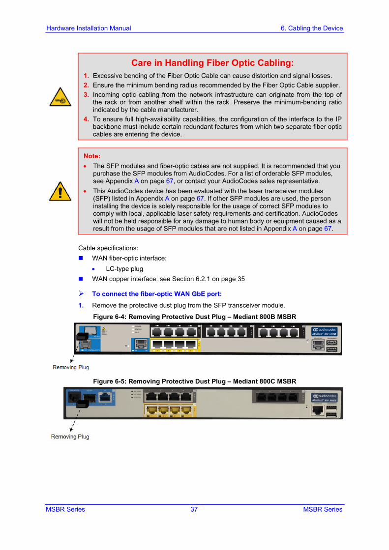
To connect the fiber-optic WAN GbE port: 1. Remove the protective dust plug from the SFP transceiver module.
Figure 6-4: Removing Protective Dust Plug – Mediant 800B MSBR
Figure 6-5: Removing Protective Dust Plug – Mediant 800C MSBR
Hardware Installation Manual 38 Document #: LTRT-10245
Mediant 800 MSBR
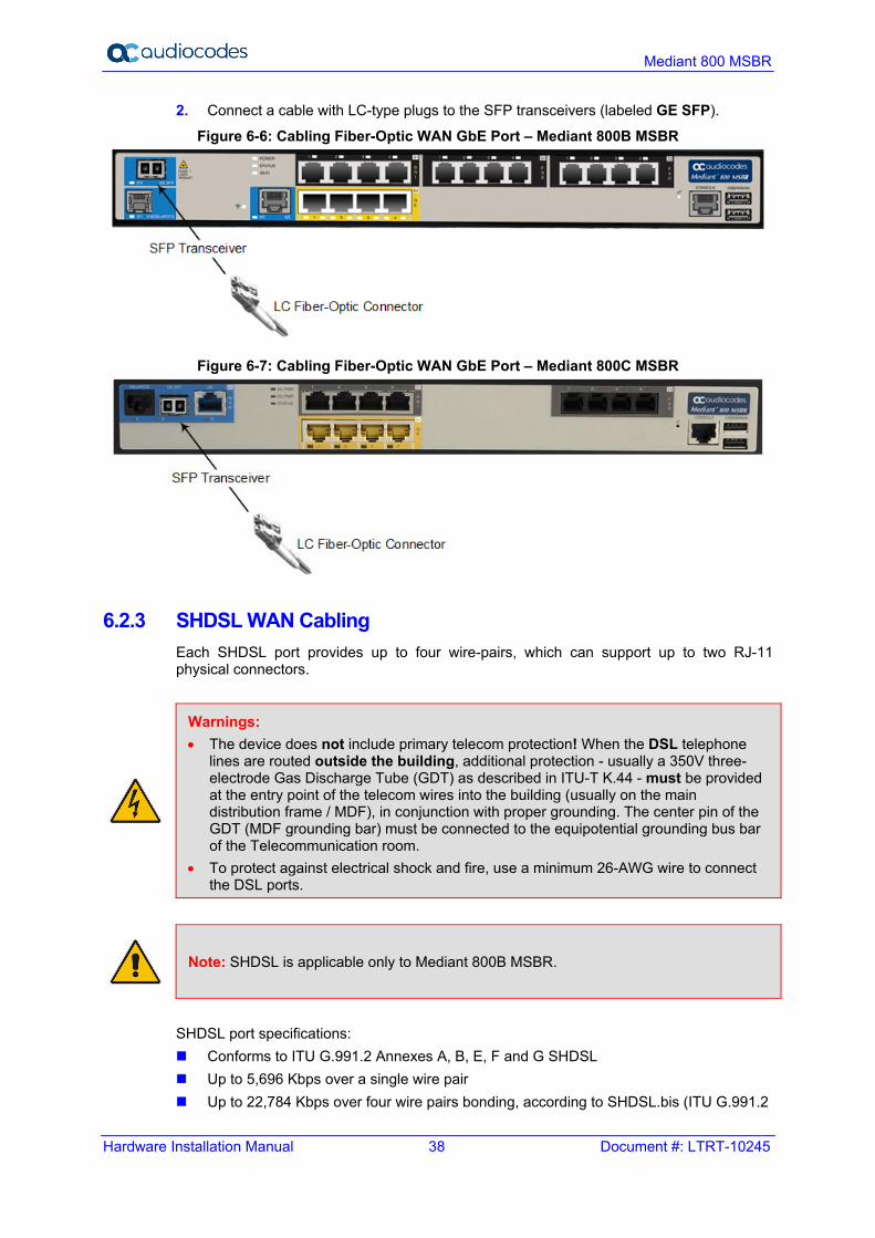
2. Connect a cable with LC-type plugs to the SFP transceivers (labeled GE SFP).
Figure 6-6: Cabling Fiber-Optic WAN GbE Port – Mediant 800B MSBR
Figure 6-7: Cabling Fiber-Optic WAN GbE Port – Mediant 800C MSBR
6.2.3 SHDSL WAN Cabling Each SHDSL port provides up to four wire-pairs, which can support up to two RJ-11 physical connectors.
Warnings: • The device does not include primary telecom protection! When the DSL telephone
lines are routed outside the building, additional protection - usually a 350V three-electrode Gas Discharge Tube (GDT) as described in ITU-T K.44 - must be provided at the entry point of the telecom wires into the building (usually on the main distribution frame / MDF), in conjunction with proper grounding. The center pin of the GDT (MDF grounding bar) must be connected to the equipotential grounding bus bar of the Telecommunication room.
• To protect against electrical shock and fire, use a minimum 26-AWG wire to connect the DSL ports.
Note: SHDSL is applicable only to Mediant 800B MSBR.
SHDSL port specifications: Conforms to ITU G.991.2 Annexes A, B, E, F and G SHDSL Up to 5,696 Kbps over a single wire pair Up to 22,784 Kbps over four wire pairs bonding, according to SHDSL.bis (ITU G.991.2
MSBR Series 39 MSBR Series
Hardware Installation Manual 6. Cabling the Device
Annexes F, G) EFM and ATM support Wetting current support on the CPE side, according to G991.2 Supports both Central Office (CO) and CPE (wetting current on CO - excluded) TC-PAM 16/32 line code Cable specification: Cable: 26-AWG min. wire Connector: RJ-11 Connector Pinouts:
Table 6-2: RJ-11 Connector Pinouts for SHDSL
Pin Function
Left RJ-11 Connector Right RJ-11 Connector
2 Pair 1 - Ring Pair 3 - Ring
3 Pair 0 - Ring Pair 2 - Ring
4 Pair 0 - Tip Pair 2 - Tip
5 Pair 1 - Tip Pair 3 - Tip
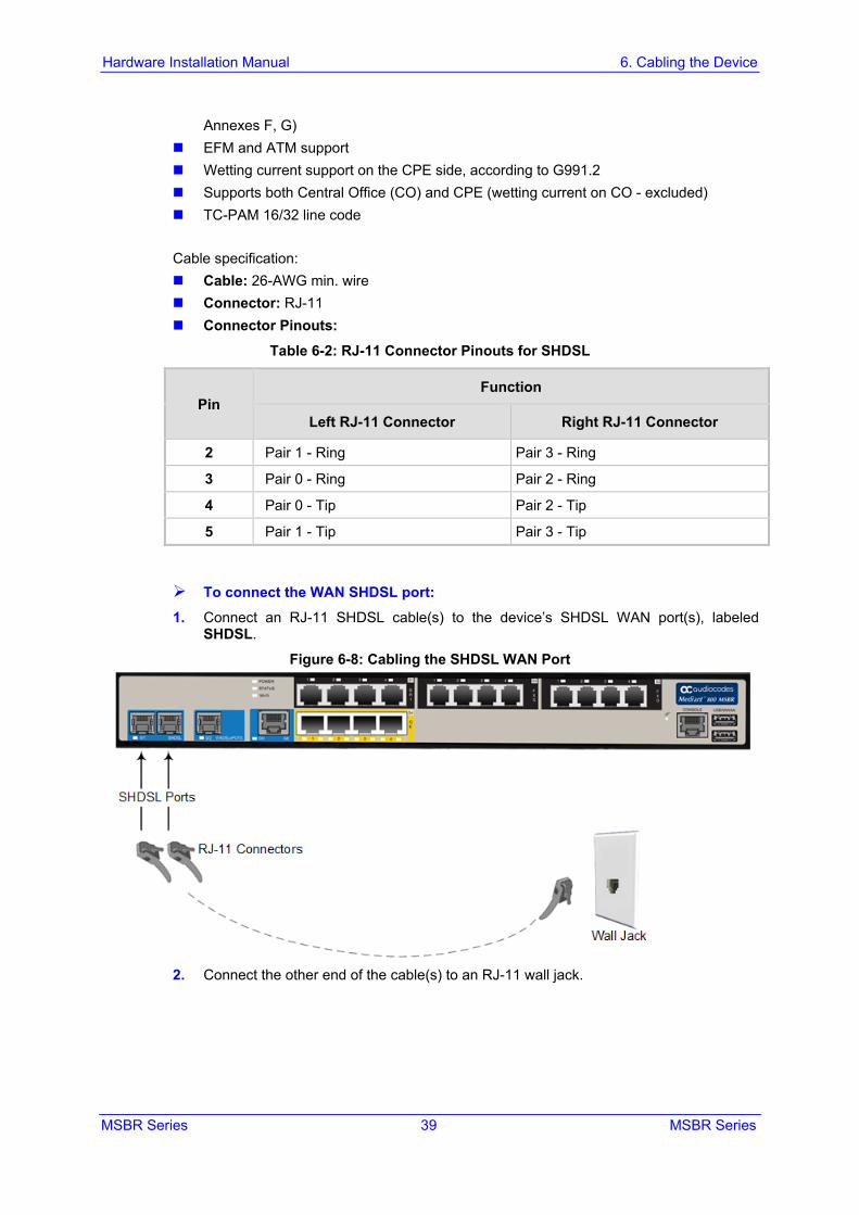
To connect the WAN SHDSL port: 1. Connect an RJ-11 SHDSL cable(s) to the device’s SHDSL WAN port(s), labeled
SHDSL.
Figure 6-8: Cabling the SHDSL WAN Port
2. Connect the other end of the cable(s) to an RJ-11 wall jack.
Hardware Installation Manual 40 Document #: LTRT-10245
Mediant 800 MSBR
6.2.4 ADSL/2+ and VDSL2 WAN Cabling The ADSL/2+ and VDSL2 (xDSL) WAN port provides a single xDSL interface through its RJ-45 port. The specifications of the xDSL interface include the following: ADSL/2+:
• RFC 2684 in Routed (IPoA) and Bridged (ETHoA) modes, supporting LLC-SNAP and VC-Multiplexed encapsulations over AAL5
• ATM UNI 4.1 compliant • UBR, CBR, VBR classes of service • RFC 2364 PPPoA • RFC 2516 PPPoE over ATM • Up to 8 PVCs
VDSL2: • ITU G.991.2 Annex E for Ethernet, also known as EFM or 2Base-TL, as defined in
IEEE 802.3ah • 802.1q VLANs over EFM • PPPoE
Warnings: • The device does not include primary telecom protection! When the DSL telephone
lines are routed outside the building, additional protection - usually a 350V three-electrode Gas Discharge Tube (GDT) as described in ITU-T K.44 - must be provided at the entry point of the telecom wires into the building (usually on the main distribution frame / MDF), in conjunction with proper grounding. The center pin of the GDT (MDF grounding bar) must be connected to the equipotential grounding bus bar of the Telecommunication room.
• To protect against electrical shock and fire, use a minimum 26-AWG wire to connect the DSL ports.
Cable specifications: Cable: 26-AWG min. wire Connector: RJ-11 or RJ-45 Connector Pinouts:
Table 6-3: RJ-11 Connector Pinouts for xDSL
Pin Function
1 Not used
2 Not used
3 CH0-P/Tip
4 CH0-N/Ring
5 Not used
6 Not used
MSBR Series 41 MSBR Series
Hardware Installation Manual 6. Cabling the Device
Table 6-4: RJ-45 Connector Pinouts for xDSL
Pin Function
1 Not used
2 Not used
3 Not used
4 CH0-P/Tip
5 CH0-N/Ring
6 Not used
7 Not used
8 Not used
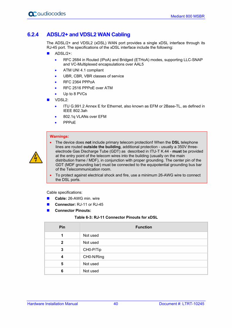
To connect the WAN xDSL WAN port: 1. Connect an RJ-11 or RJ-45 cable connector to the device’s xDSL WAN port. The port
label depends on model: • Mediant 800B MSBR: V/ADSLoISDN or ADSLoPOTS • Mediant 800C MSBR: DSLoISDN or DSLoPOTS
2. Connect the other end of the cable to the DSL wall jack through an xDSL filter with splitter.
Figure 6-9: Cabling xDSL WAN Port – Mediant 800B MSBR
Hardware Installation Manual 42 Document #: LTRT-10245
Mediant 800 MSBR
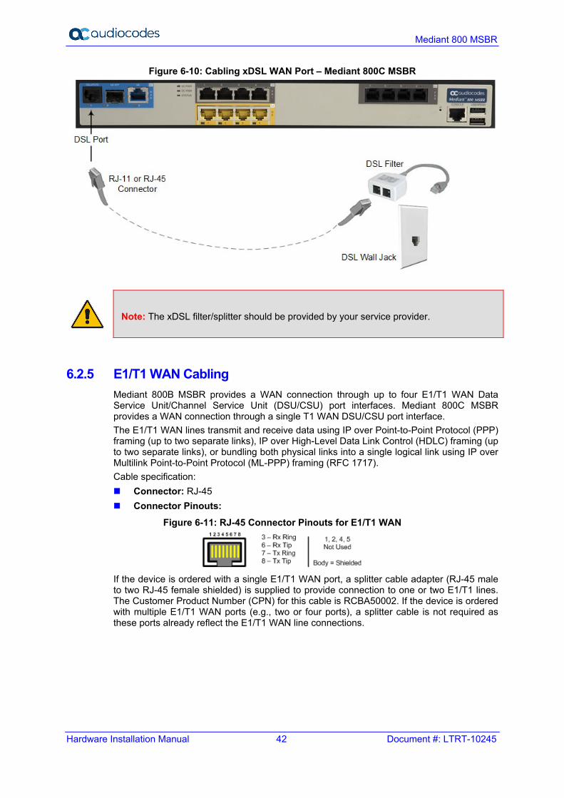
Figure 6-10: Cabling xDSL WAN Port – Mediant 800C MSBR
Note: The xDSL filter/splitter should be provided by your service provider.
6.2.5 E1/T1 WAN Cabling Mediant 800B MSBR provides a WAN connection through up to four E1/T1 WAN Data Service Unit/Channel Service Unit (DSU/CSU) port interfaces. Mediant 800C MSBR provides a WAN connection through a single T1 WAN DSU/CSU port interface. The E1/T1 WAN lines transmit and receive data using IP over Point-to-Point Protocol (PPP) framing (up to two separate links), IP over High-Level Data Link Control (HDLC) framing (up to two separate links), or bundling both physical links into a single logical link using IP over Multilink Point-to-Point Protocol (ML-PPP) framing (RFC 1717). Cable specification: Connector: RJ-45 Connector Pinouts:
Figure 6-11: RJ-45 Connector Pinouts for E1/T1 WAN
If the device is ordered with a single E1/T1 WAN port, a splitter cable adapter (RJ-45 male to two RJ-45 female shielded) is supplied to provide connection to one or two E1/T1 lines. The Customer Product Number (CPN) for this cable is RCBA50002. If the device is ordered with multiple E1/T1 WAN ports (e.g., two or four ports), a splitter cable is not required as these ports already reflect the E1/T1 WAN line connections.
MSBR Series 43 MSBR Series
Hardware Installation Manual 6. Cabling the Device
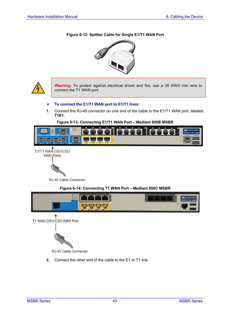
Figure 6-12: Splitter Cable for Single E1/T1 WAN Port
Warning: To protect against electrical shock and fire, use a 26 AWG min wire to connect the T1 WAN port.
To connect the E1/T1 WAN port to E1/T1 lines: 1. Connect the RJ-45 connector on one end of the cable to the E1/T1 WAN port, labeled
T1E1.
Figure 6-13: Connecting E1/T1 WAN Port – Mediant 800B MSBR
Figure 6-14: Connecting T1 WAN Port – Mediant 800C MSBR
2. Connect the other end of the cable to the E1 or T1 line.
Hardware Installation Manual 44 Document #: LTRT-10245
Mediant 800 MSBR
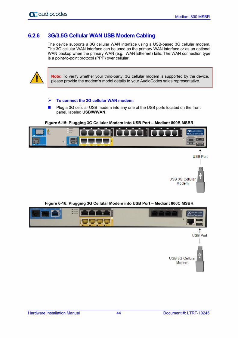
6.2.6 3G/3.5G Cellular WAN USB Modem Cabling The device supports a 3G cellular WAN interface using a USB-based 3G cellular modem. The 3G cellular WAN interface can be used as the primary WAN interface or as an optional WAN backup when the primary WAN (e.g., WAN Ethernet) fails. The WAN connection type is a point-to-point protocol (PPP) over cellular.
Note: To verify whether your third-party, 3G cellular modem is supported by the device, please provide the modem's model details to your AudioCodes sales representative.
To connect the 3G cellular WAN modem: Plug a 3G cellular USB modem into any one of the USB ports located on the front
panel, labeled USB/WWAN.
Figure 6-15: Plugging 3G Cellular Modem into USB Port – Mediant 800B MSBR
Figure 6-16: Plugging 3G Cellular Modem into USB Port – Mediant 800C MSBR

MSBR Series 45 MSBR Series
Hardware Installation Manual 6. Cabling the Device
6.3 Connecting to LAN The device provides up to four Gigabit Ethernet (10/100/1000Base-T) LAN RJ-45, ports and eight RJ-45 10/100Base-TX (Fast Ethernet) LAN ports for connection to the LAN (e.g., computers, switches, and IP phones). These ports support half- and full-duplex modes, auto-negotiation, and straight or crossover cable detection. The LAN ports can also support PoE. For connecting PoE-enabled equipment to the LAN ports, see Section 6.4 on page 46. Cable specification: Cable: Category 5e or Category 6 shielded twisted pair (STP) straight-through Connector: RJ-45 Connector Pinouts:
Table 6-5: RJ-45 Connector Pinouts for GbE/FE with PoE
Pin Signal Name
1 Ethernet signal pair (10/100/1000Base-T) and PoE NEG
2
3 Ethernet signal pair (10/100/1000Base-T) and PoE POS
6
4 Ethernet signal pair (1000Base-T)
5
7 Ethernet signal pair (1000Base-T)
8
Shield Chassis ground
To connect the device to the LAN: 1. Connect one end of the Ethernet cable to the RJ-45 port labeled GE (for Gigabit
Ethernet ports) and/or FE (for Fast Ethernet ports).
Figure 6-17: Cabling LAN Ports – Mediant 800B MSBR

Hardware Installation Manual 46 Document #: LTRT-10245
Mediant 800 MSBR
Figure 6-18: Cabling LAN Ports – Mediant 800C MSBR
2. Connect the other end of the cable to the Gigabit Ethernet network (for the GE ports)
and/or Fast Ethernet network (for the FE ports).
6.4 Connecting PoE-Enabled Clients to LAN Ports The LAN ports support PoE according to the IEEE 802.3af-2003 and IEEE 802.3at standards. The ports can transfer electrical power, along with the usual data, over the Ethernet cable to connected equipment (e.g., IP phone) capable of receiving PoE. The LAN ports automatically detect the presence of IEEE 802.3 compliant equipment. Upon plugging in a PoE client to one of the ports, the device also automatically detects the class to which the client belongs and consequently, the maximum power allowed: IEEE 802.3af-2003: The device can supply up to 15.4W per port, and a total budget of
50W or 120W (depending on device model) for all ports: • Class 0: configurable, up to 15.4W – refer to the User's Manual for more
information • Class 1: up to 4W • Class 2: up to 7W • Class 3: up to 15.4W
IEEE 802.3at – Class 4: The device can supply up to 30W per port to the connected equipment and a total budget of 50W, 120W, or 200W (depending on device model) for all ports.
If the plugged-in client is detected as Class 0, the device saves the user-defined wattage from the total wattage budget (default is 15.4W). If the plugged-in client is detected as Class 1, Class 2, or Class 3, the device saves 4W, 7W, or 15.4W respectively from the total wattage budget. If the power budget has been exhausted and a new client is plugged in, no power is available to this client. Note that the power is always taken off the total budget according to the class detected, regardless of what is actually consumed per port. PoE is supplied on Pins 4,5: (+), and pins 7,8: (-).
MSBR Series 47 MSBR Series
Hardware Installation Manual 6. Cabling the Device
Note:
• PoE support is a customer ordered feature. • Upon device startup, PoE is enabled on all ports. You can enable or disable PoE per
port. For more information, refer to the User's Manual. • For PoE support, the maximum cable length between the device's Ethernet port and
the connected equipment (e.g., IP phone) is 100 meters. • You can configure the maximum port power consumption (up to 15.4W) used when
the plugged-in client is detected as Class 0. You can also enable Class 4 PoE per port. For more information, refer to the User's Manual.
To connect PoE-enabled equipment to the PoE-enabled LAN ports: 1. Connect one end of a straight-through RJ-45 Cat 5e or Cat 6 cable to a LAN port
enabled with PoE. 2. Connect the other end of the cable to PoE-enabled equipment (e.g., an IP Phone).
6.5 Analog Interfaces This section describes how to connect the device to analog equipment.
6.5.1 Connecting FXS Interfaces The procedure below describes how to cable the device's FXS interfaces.
Warnings: • The device is an INDOOR unit and therefore, must be installed only indoors. • Ensure that the FXS ports are connected to the appropriate, external devices;
otherwise, damage to the device may occur. • FXS ports are considered TNV-2.
Notes: • FXS interface is a separate orderable item. • FXS is the interface replacing the Exchange (i.e., the CO or the PBX) and connects to
analog telephones, dial-up modems, and fax machines. The FXS is designed to supply line voltage and ringing current to these telephone devices. An FXS VoIP device interfaces between the analog telephone devices and the Internet.
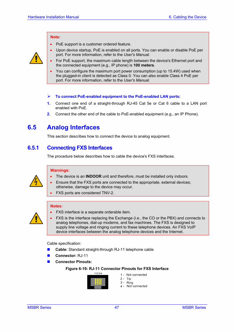
Cable specification: Cable: Standard straight-through RJ-11 telephone cable Connector: RJ-11 Connector Pinouts:
Figure 6-19: RJ-11 Connector Pinouts for FXS Interface
Hardware Installation Manual 48 Document #: LTRT-10245
Mediant 800 MSBR
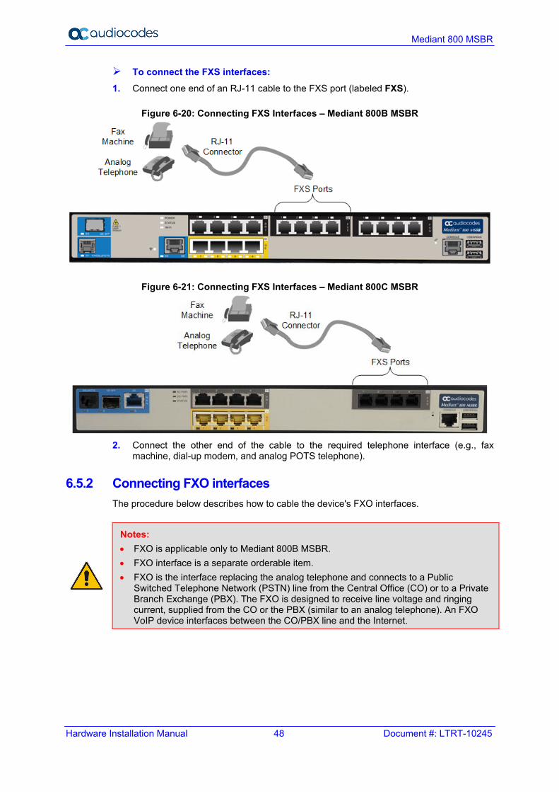
To connect the FXS interfaces: 1. Connect one end of an RJ-11 cable to the FXS port (labeled FXS).
Figure 6-20: Connecting FXS Interfaces – Mediant 800B MSBR
Figure 6-21: Connecting FXS Interfaces – Mediant 800C MSBR
2. Connect the other end of the cable to the required telephone interface (e.g., fax
machine, dial-up modem, and analog POTS telephone).
6.5.2 Connecting FXO interfaces The procedure below describes how to cable the device's FXO interfaces.
Notes: • FXO is applicable only to Mediant 800B MSBR. • FXO interface is a separate orderable item. • FXO is the interface replacing the analog telephone and connects to a Public
Switched Telephone Network (PSTN) line from the Central Office (CO) or to a Private Branch Exchange (PBX). The FXO is designed to receive line voltage and ringing current, supplied from the CO or the PBX (similar to an analog telephone). An FXO VoIP device interfaces between the CO/PBX line and the Internet.
MSBR Series 49 MSBR Series
Hardware Installation Manual 6. Cabling the Device
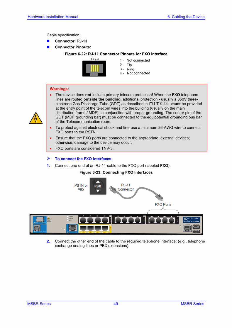
Cable specification: Connector: RJ-11 Connector Pinouts:
Figure 6-22: RJ-11 Connector Pinouts for FXO Interface
Warnings: • The device does not include primary telecom protection! When the FXO telephone
lines are routed outside the building, additional protection - usually a 350V three-electrode Gas Discharge Tube (GDT) as described in ITU-T K.44 - must be provided at the entry point of the telecom wires into the building (usually on the main distribution frame / MDF), in conjunction with proper grounding. The center pin of the GDT (MDF grounding bar) must be connected to the equipotential grounding bus bar of the Telecommunication room.
• To protect against electrical shock and fire, use a minimum 26-AWG wire to connect FXO ports to the PSTN.
• Ensure that the FXO ports are connected to the appropriate, external devices; otherwise, damage to the device may occur.
• FXO ports are considered TNV-3.
To connect the FXO interfaces: 1. Connect one end of an RJ-11 cable to the FXO port (labeled FXO).
Figure 6-23: Connecting FXO Interfaces
2. Connect the other end of the cable to the required telephone interface: (e.g., telephone
exchange analog lines or PBX extensions).
Hardware Installation Manual 50 Document #: LTRT-10245
Mediant 800 MSBR
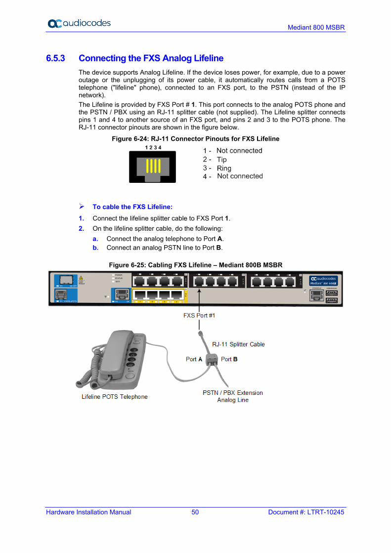
6.5.3 Connecting the FXS Analog Lifeline The device supports Analog Lifeline. If the device loses power, for example, due to a power outage or the unplugging of its power cable, it automatically routes calls from a POTS telephone ("lifeline" phone), connected to an FXS port, to the PSTN (instead of the IP network). The Lifeline is provided by FXS Port # 1. This port connects to the analog POTS phone and the PSTN / PBX using an RJ-11 splitter cable (not supplied). The Lifeline splitter connects pins 1 and 4 to another source of an FXS port, and pins 2 and 3 to the POTS phone. The RJ-11 connector pinouts are shown in the figure below.
Figure 6-24: RJ-11 Connector Pinouts for FXS Lifeline
To cable the FXS Lifeline: 1. Connect the lifeline splitter cable to FXS Port 1. 2. On the lifeline splitter cable, do the following:
a. Connect the analog telephone to Port A. b. Connect an analog PSTN line to Port B.
Figure 6-25: Cabling FXS Lifeline – Mediant 800B MSBR

MSBR Series 51 MSBR Series
Hardware Installation Manual 6. Cabling the Device
Figure 6-26: Cabling FXS Lifeline – Mediant 800C MSBR
Notes:
• The lifeline splitter cable is a separate orderable item. • Analog Lifeline cabling is applicable only if the device is ordered with FXS interfaces. • The number of supported Lifelines depends on the device’s hardware configuration.
For the combined FXS/FXO configuration, one Lifeline is available; for the 12-FXS configuration, up to three Lifelines are available.
6.6 ISDN BRI Interfaces
6.6.1 Connecting to BRI Lines The device provides up to eight BRI S/T ports. These ports connect to ISDN terminal equipment such as ISDN telephones. Each BRI port can be configured either as termination equipment/user side (TE) or network termination/network side (NT). Up to eight terminal equipment (TE) devices can be connected per BRI S/T port, using an ISDN S-bus that provides eight ISDN ports. When configured as NT, the BRI port drives a nominal voltage of 38 V with limited current supply of up to 100 mA. Cable specification: Cable: 26 AWG min. wire Connector: RJ-45 Connector Pinouts:
Figure 6-27: RJ-45 Connector Pinouts for BRI Ports
Hardware Installation Manual 52 Document #: LTRT-10245
Mediant 800 MSBR
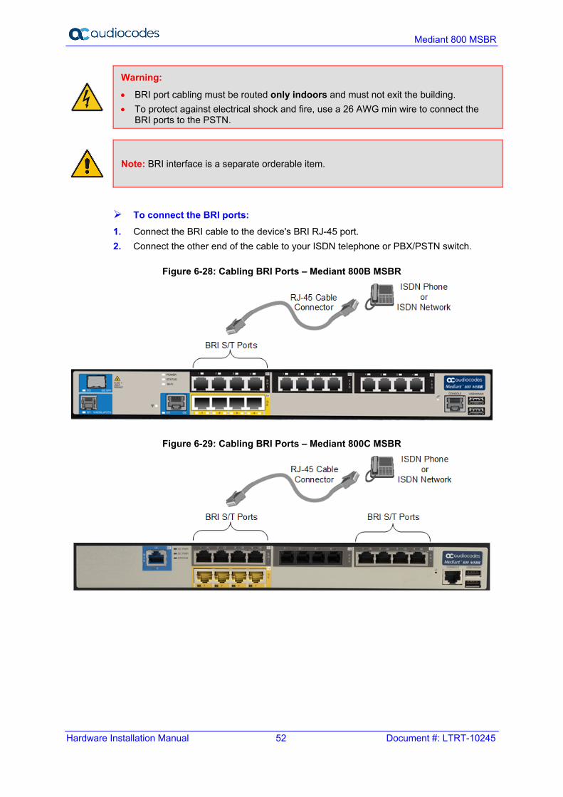
Warning:
• BRI port cabling must be routed only indoors and must not exit the building. • To protect against electrical shock and fire, use a 26 AWG min wire to connect the
BRI ports to the PSTN.
Note: BRI interface is a separate orderable item.
To connect the BRI ports: 1. Connect the BRI cable to the device's BRI RJ-45 port. 2. Connect the other end of the cable to your ISDN telephone or PBX/PSTN switch.
Figure 6-28: Cabling BRI Ports – Mediant 800B MSBR
Figure 6-29: Cabling BRI Ports – Mediant 800C MSBR
MSBR Series 53 MSBR Series
Hardware Installation Manual 6. Cabling the Device
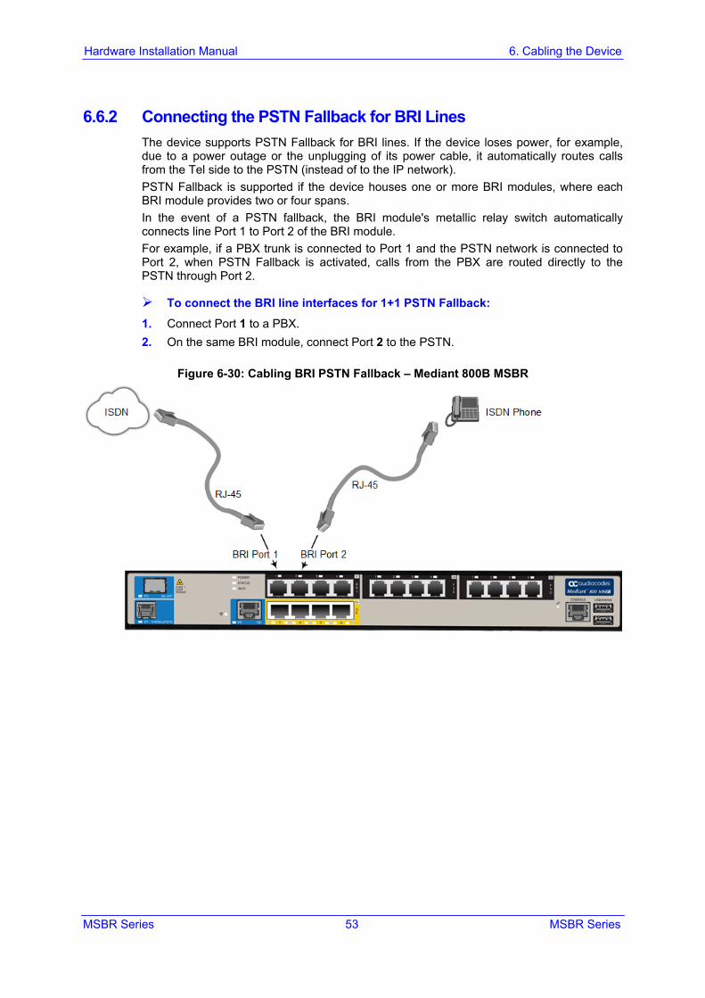
6.6.2 Connecting the PSTN Fallback for BRI Lines The device supports PSTN Fallback for BRI lines. If the device loses power, for example, due to a power outage or the unplugging of its power cable, it automatically routes calls from the Tel side to the PSTN (instead of to the IP network). PSTN Fallback is supported if the device houses one or more BRI modules, where each BRI module provides two or four spans. In the event of a PSTN fallback, the BRI module's metallic relay switch automatically connects line Port 1 to Port 2 of the BRI module. For example, if a PBX trunk is connected to Port 1 and the PSTN network is connected to Port 2, when PSTN Fallback is activated, calls from the PBX are routed directly to the PSTN through Port 2.
To connect the BRI line interfaces for 1+1 PSTN Fallback: 1. Connect Port 1 to a PBX. 2. On the same BRI module, connect Port 2 to the PSTN.
Figure 6-30: Cabling BRI PSTN Fallback – Mediant 800B MSBR

Hardware Installation Manual 54 Document #: LTRT-10245
Mediant 800 MSBR
Figure 6-31: Cabling BRI PSTN Fallback – Mediant 800C MSBR
Notes:
• BRI port cabling must be routed only indoors and must not exit the building. • PSTN Fallback is supported only on the BRI module. • PSTN Fallback is supported only between ports on the same BRI module. • This PSTN Fallback feature has no relation to the PSTN Fallback Software Upgrade
Key.
6.7 Connecting to ISDN PRI (E1/T1) Trunks The procedure below describes how to cable the device's E1/T1 trunk.
Warning:
• PRI port cabling must be routed only indoors and must not exit the building. • To protect against electrical shock and fire, use a 26 AWG min wire to connect T1 or
E1 ports to the PSTN. • To comply with EMC rules and regulations, use shielded twisted pair (STP) cables for
E1 interfaces on the Mediant 800B MSBR model.
Cable specification: Cable: 26 AWG min. wire Connector: RJ-48c Connector Pinouts:
Figure 6-32: RJ-48c Connector Pinouts for E1/T1
MSBR Series 55 MSBR Series
Hardware Installation Manual 6. Cabling the Device
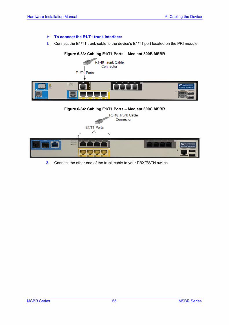
To connect the E1/T1 trunk interface: 1. Connect the E1/T1 trunk cable to the device’s E1/T1 port located on the PRI module.
Figure 6-33: Cabling E1/T1 Ports – Mediant 800B MSBR
Figure 6-34: Cabling E1/T1 Ports – Mediant 800C MSBR
2. Connect the other end of the trunk cable to your PBX/PSTN switch.
Hardware Installation Manual 56 Document #: LTRT-10245
Mediant 800 MSBR
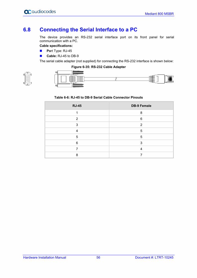
6.8 Connecting the Serial Interface to a PC The device provides an RS-232 serial interface port on its front panel for serial communication with a PC. Cable specifications: Port Type: RJ-45 Cable: RJ-45 to DB-9 The serial cable adapter (not supplied) for connecting the RS-232 interface is shown below:
Figure 6-35: RS-232 Cable Adapter
Table 6-6: RJ-45 to DB-9 Serial Cable Connector Pinouts
RJ-45 DB-9 Female
1 8
2 6
3 2
4 5
5 5
6 3
7 4
8 7
MSBR Series 57 MSBR Series
Hardware Installation Manual 6. Cabling the Device
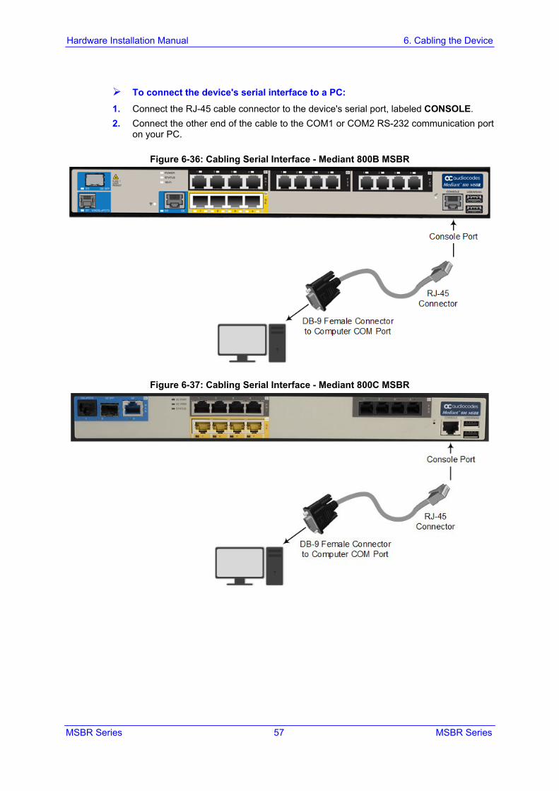
To connect the device's serial interface to a PC: 1. Connect the RJ-45 cable connector to the device's serial port, labeled CONSOLE. 2. Connect the other end of the cable to the COM1 or COM2 RS-232 communication port
on your PC.
Figure 6-36: Cabling Serial Interface - Mediant 800B MSBR
Figure 6-37: Cabling Serial Interface - Mediant 800C MSBR
Hardware Installation Manual 58 Document #: LTRT-10245
Mediant 800 MSBR
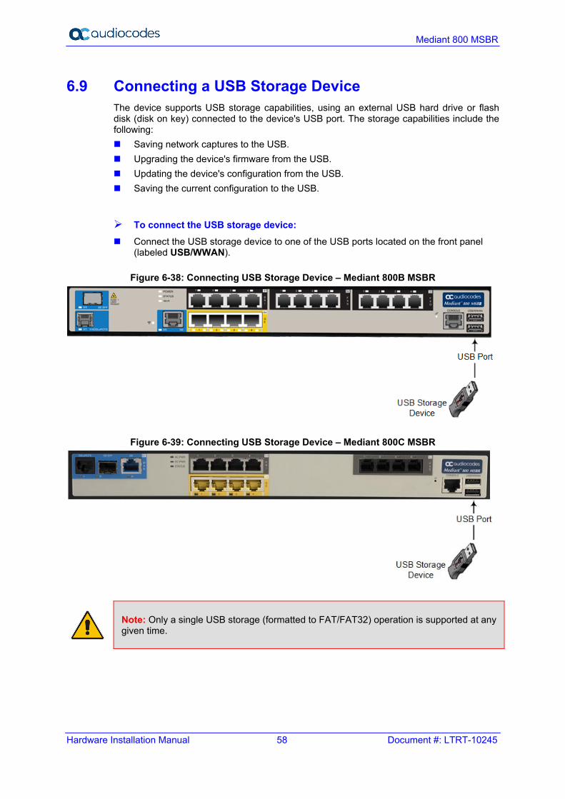
6.9 Connecting a USB Storage Device The device supports USB storage capabilities, using an external USB hard drive or flash disk (disk on key) connected to the device's USB port. The storage capabilities include the following: Saving network captures to the USB. Upgrading the device's firmware from the USB. Updating the device's configuration from the USB. Saving the current configuration to the USB.
To connect the USB storage device: Connect the USB storage device to one of the USB ports located on the front panel
(labeled USB/WWAN).
Figure 6-38: Connecting USB Storage Device – Mediant 800B MSBR
Figure 6-39: Connecting USB Storage Device – Mediant 800C MSBR
Note: Only a single USB storage (formatted to FAT/FAT32) operation is supported at any given time.

MSBR Series 59 MSBR Series
Hardware Installation Manual 6. Cabling the Device
6.10 Connecting the OSN Server The device may be ordered with an embedded, Open Network Solution (OSN) platform for hosting third-party services such as an IP PBX. The OSN modules are located on the device's rear panel. The available, orderable OSN server platforms are listed in the table below.
Table 6-7: OSN Server Platforms
OSN Platform
CPU Memory Storage Interfaces
OSN2 2nd Generation Intel Core Celeron 1.6 GHz
2 or 4 GB HDD 500 GB Two external Gigabit Ethernet Internal Gigabit Ethernet Three USB 2.0 via Connection
Module VGA
OSN4 3rd Generation Intel Core i7 Quad Core
16 GB ECC DDR3
HDD (500 GB) or SSD (240 GB)
Two external Gigabit Ethernet Internal Gigabit Ethernet Three USB 2.0 via Connection
Module VGA
OSN5 Intel Atom N2800 1.86 GHz Dual Core
2G HDD 500 GB External Gigabit Ethernet Internal Gigabit Ethernet Three USB 2.0 via Connection
Module VGA
Notes:
• The OSN server platform is a customer ordered feature and thus, the OSN interface ports, located on the rear panel are available only when the device is purchased with the OSN server.
• The OSN server also provides an internal interface connection to the device's LAN switch. In other words, instead of using the Gigabit Ethernet port on the rear panel, you can use the LAN port #1 located on the front panel for connecting to the OSN server.
• The table above lists the currently available OSN platforms. This list may change without notice. To check for any updated information on available OSN platforms, contact your AudioCodes sales representative.
Hardware Installation Manual 60 Document #: LTRT-10245
Mediant 800 MSBR
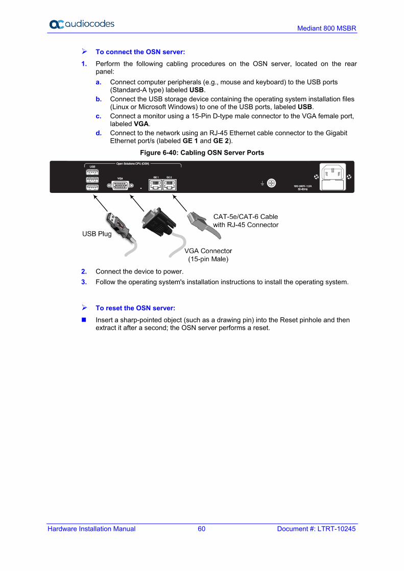
To connect the OSN server: 1. Perform the following cabling procedures on the OSN server, located on the rear
panel: a. Connect computer peripherals (e.g., mouse and keyboard) to the USB ports
(Standard-A type) labeled USB. b. Connect the USB storage device containing the operating system installation files
(Linux or Microsoft Windows) to one of the USB ports, labeled USB. c. Connect a monitor using a 15-Pin D-type male connector to the VGA female port,
labeled VGA. d. Connect to the network using an RJ-45 Ethernet cable connector to the Gigabit
Ethernet port/s (labeled GE 1 and GE 2).
Figure 6-40: Cabling OSN Server Ports
2. Connect the device to power. 3. Follow the operating system's installation instructions to install the operating system.
To reset the OSN server: Insert a sharp-pointed object (such as a drawing pin) into the Reset pinhole and then
extract it after a second; the OSN server performs a reset.

MSBR Series 61 MSBR Series
Hardware Installation Manual 6. Cabling the Device
6.11 Connecting to Power The supported power type depends on the Mediant 800 hardware revision: Mediant 800B MSBR: Only AC power Mediant 800C MSBR: AC and DC redundant power. When both power supplies are
used (AC and DC), the device is powered from the AC power source only. The DC source starts feeding the device only upon an AC power outage.
Notes: For Mediant 800C MSBR, the device is always shipped with AC power support. DC power is also available if the device is ordered with DC support (AC/DC power adaptor is provided).
6.11.1 Connecting to AC Power The device receives power from a standard alternating current (AC) electrical outlet. The connection is made using the supplied AC power cord.
Table 6-8: AC Power Specifications
Physical Specification Value
Input Voltage Single universal AC power supply 100 to 240V
AC Input Frequency 50 to 60 Hz
AC Input Current Mediant 800B MSBR: 4 A max. (with PoE) Mediant 800C MSBR: 2.5 A (max.)
Max. Power Consumption SBC Only (no PSTN): 27W Gateway (without OSN): 60W*
With PoE option: 300W * Power consumption varies according to the assembled hardware configuration.
Warnings:
• The device must be connected to a socket-outlet providing a protective earthing connection.
• To avoid electric shock or fire, use only the AC power cord that is supplied by AudioCodes with the device.
• For replacing the power fuse, see Section 7 on page 65.
ご注意
本製品に添付の電源ケーブルは、Mediant 800 MSBR に専用設計されているため、汎用性がありません. 本電源ケーブルを他の機器に使用されないよう、ご注意ください.
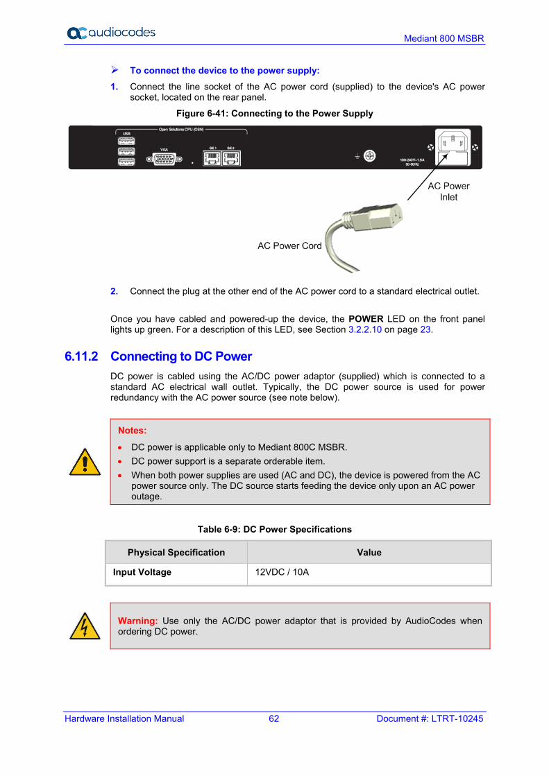
Hardware Installation Manual 62 Document #: LTRT-10245
Mediant 800 MSBR
To connect the device to the power supply: 1. Connect the line socket of the AC power cord (supplied) to the device's AC power
socket, located on the rear panel.
Figure 6-41: Connecting to the Power Supply
2. Connect the plug at the other end of the AC power cord to a standard electrical outlet. Once you have cabled and powered-up the device, the POWER LED on the front panel lights up green. For a description of this LED, see Section 3.2.2.10 on page 23.
6.11.2 Connecting to DC Power DC power is cabled using the AC/DC power adaptor (supplied) which is connected to a standard AC electrical wall outlet. Typically, the DC power source is used for power redundancy with the AC power source (see note below).
Notes:
• DC power is applicable only to Mediant 800C MSBR. • DC power support is a separate orderable item. • When both power supplies are used (AC and DC), the device is powered from the AC
power source only. The DC source starts feeding the device only upon an AC power outage.
Table 6-9: DC Power Specifications
Physical Specification Value
Input Voltage 12VDC / 10A
Warning: Use only the AC/DC power adaptor that is provided by AudioCodes when ordering DC power.
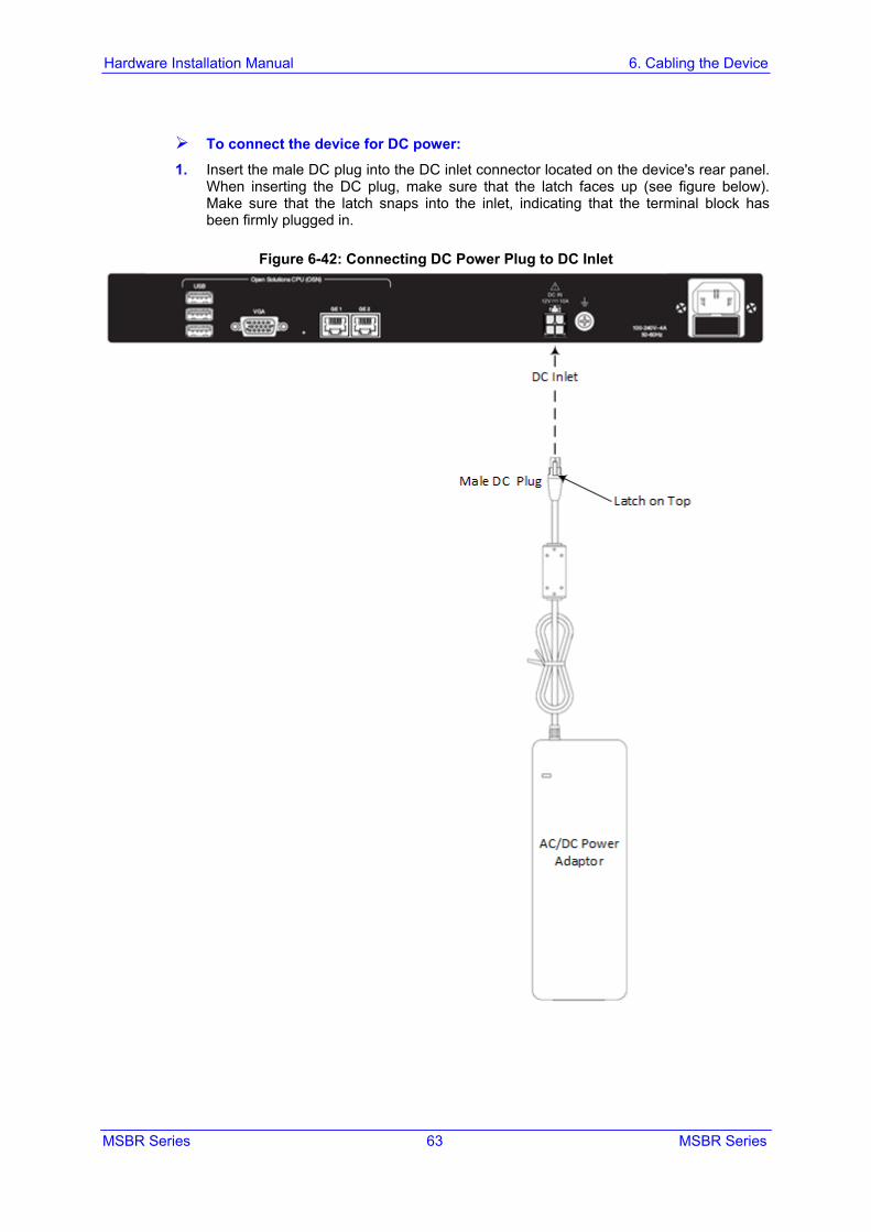
MSBR Series 63 MSBR Series
Hardware Installation Manual 6. Cabling the Device
To connect the device for DC power: 1. Insert the male DC plug into the DC inlet connector located on the device's rear panel.
When inserting the DC plug, make sure that the latch faces up (see figure below). Make sure that the latch snaps into the inlet, indicating that the terminal block has been firmly plugged in.
Figure 6-42: Connecting DC Power Plug to DC Inlet
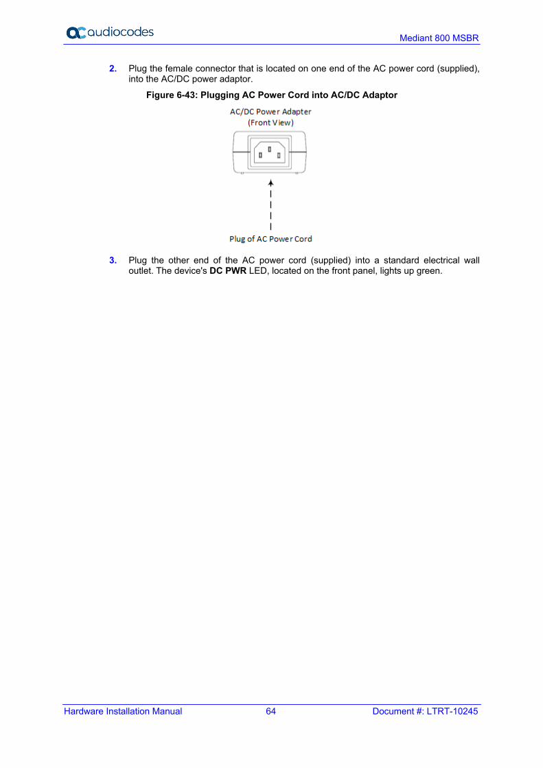
Hardware Installation Manual 64 Document #: LTRT-10245
Mediant 800 MSBR
2. Plug the female connector that is located on one end of the AC power cord (supplied), into the AC/DC power adaptor.
Figure 6-43: Plugging AC Power Cord into AC/DC Adaptor
3. Plug the other end of the AC power cord (supplied) into a standard electrical wall
outlet. The device's DC PWR LED, located on the front panel, lights up green.
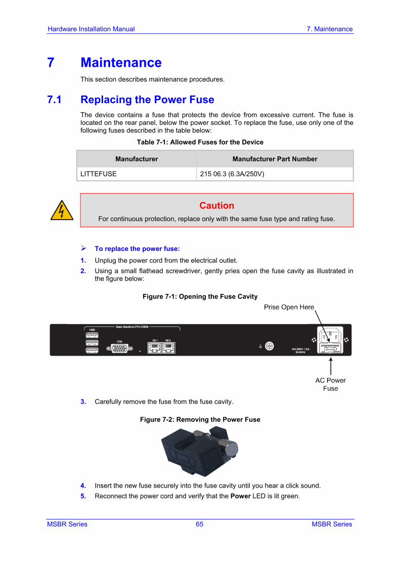
MSBR Series 65 MSBR Series
Hardware Installation Manual 7. Maintenance
7 Maintenance This section describes maintenance procedures.
7.1 Replacing the Power Fuse The device contains a fuse that protects the device from excessive current. The fuse is located on the rear panel, below the power socket. To replace the fuse, use only one of the following fuses described in the table below:
Table 7-1: Allowed Fuses for the Device
Manufacturer Manufacturer Part Number
LITTEFUSE 215 06.3 (6.3A/250V)
Caution For continuous protection, replace only with the same fuse type and rating fuse.
To replace the power fuse: 1. Unplug the power cord from the electrical outlet. 2. Using a small flathead screwdriver, gently pries open the fuse cavity as illustrated in
the figure below:
Figure 7-1: Opening the Fuse Cavity
3. Carefully remove the fuse from the fuse cavity.
Figure 7-2: Removing the Power Fuse
4. Insert the new fuse securely into the fuse cavity until you hear a click sound. 5. Reconnect the power cord and verify that the Power LED is lit green.

Hardware Installation Manual 66 Document #: LTRT-10245
Mediant 800 MSBR
This page is intentionally left blank.
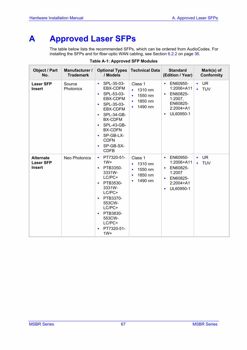
MSBR Series 67 MSBR Series
Hardware Installation Manual A. Approved Laser SFPs
A Approved Laser SFPs The table below lists the recommended SFPs, which can be ordered from AudioCodes. For installing the SFPs and for fiber-optic WAN cabling, see Section 6.2.2 on page 36.
Table A-1: Approved SFP Modules
Object / Part No.
Manufacturer / Trademark
Optional Types / Models
Technical Data Standard (Edition / Year)
Mark(s) of Conformity
Laser SFP Insert
Source Photonics
SPL-35-03-EBX-CDFM
SPL-53-03-EBX-CDFM
SPL-35-03-EBX-CDFM
SPL-34-GB-BX-CDFM
SPL-43-GB-BX-CDFN
SP-GB-LX-CDFN
SP-GB-SX-CDFB
Class 1 1310 nm 1550 nm 1850 nm 1490 nm
EN60950-1:2006+A11
EN60825-1:2007, EN60825-2:2004+A1
UL60950-1
UR TUV
Alternate Laser SFP Insert
Neo Photonics PT7320-51-1W+
PTB3350-3331W-LC/PC+
PTB3530-3331W-LC/PC+
PTB3370-553CW-LC/PC+
PTB3830-553CW-LC/PC+
PT7320-51-1W+
Class 1 1310 nm 1550 nm 1850 nm 1490 nm
EN60950-1:2006+A11
EN60825-1:2007
EN60825-2:2004+A1
UL60950-1
UR TUV

Hardware Installation Manual 68 Document #: LTRT-10245
Mediant 800 MSBR
This page is intentionally left blank.

MSBR Series 69 MSBR Series
Hardware Installation Manual B. Notice for Installing CentOS Version 4.7 on OSN Server
B Notice for Installing CentOS Version 4.7 on OSN Server This appendix provides important information when installing CentOS Ver. 4.7 Linux Distribution on the OSN server: When installing CentOS, ensure that you type linux irqpoll at the boot: prompt. For CentOS to identify the OSN server’s Gigabit Ethernet (GE) interfaces, do the
following: 1. Obtain the following files from AudioCodes:
♦ Binary compiled CentOS 4.7 driver for Intel e1000e Ethernet controller on Mediant 800 MSBR (e1000e.ko)
♦ Manual pages (e1000e.7.gz) 2. Copy the files to the /root directory. 3. Remove any old e1000e modules (if any) and install the new module and manual
pages: #> find /lib/modules/2.6.9-78.ELsmp –name e1000e.ko –exec rm –rf {}\; #> find /lib/modules/2.6.9-78.ELsmp –name e1000e.ko.gz –exec rm –rf {}\; #> install –D –m 644 /root/e1000e.ko /lib/modules/2.6.9-78.ELsmp/kernel/drivers/net/e1000e/e1000e.ko #> /sbin/depmod –a #> echo “alias eth1 e1000e” >> /etc/modprobe.conf #> echo “alias eth2 e1000e” >> /etc/modprobe.conf #> install –D –m 644 /root/e1000e.7.gz /usr/share/man/man7/e1000e.7.gz #> man –c –P`cat > /dev/null` e1000e #> modprobe e1000e
Note: The character #> depicts the CLI prompt and is not part of the command. 4. Restart networking, by running the following command:
#> service network restart
Note: The character #> depicts the CLI prompt (i.e., this is not part of the command). The final result should be as follows: Eth0 = r8169 (INTERNAL and not in use) Eth1 = e1000e (GE LAN) Eth2 = e1000e (GE LAN)

International Headquarters 1 Hayarden Street, Airport City Lod 7019900, Israel Tel: +972-3-976-4000 Fax: +972-3-976-4040 AudioCodes Inc. 200 Cottontail Lane, Suite A101E, Somerset NJ 08873 Tel: +1-732-469-0880 Fax: +1-732-469-2298 Contact us: https://www.audiocodes.com/corporate/offices-worldwide Website: https://www.audiocodes.com/ ©2019 AudioCodes Ltd. All rights reserved. AudioCodes, AC, HD VoIP, HD VoIP Sounds Better, IPmedia, Mediant, MediaPack, What’s Inside Matters, OSN, SmartTAP, User Management Pack, VMAS, VoIPerfect, VoIPerfectHD, Your Gateway To VoIP, 3GX, VocaNom, AudioCodes One Voice and CloudBond are trademarks or registered trademarks of AudioCodes Limited. All other products or trademarks are property of their respective owners. Product specifications are subject to change without notice. Document #: LTRT-10231