meduim voltage circuit breaker course chapter 7.0 student manual
TRANSCRIPT

Meduim Voltage Circuit Breaker Course Chapter 7.0 Student Manual Westinghouse DHP Circuit breakers
USNRC 7-1 Rev 0
7.0 INTRODUCTION TO DHP CIRCUIT BREAKERS
Learning Objectives
Provide attendees with a basic understanding of the DHP breaker and its purpose, operation and construction.
As a result of this lesson you will be able to understand:
1. The basic function of the DHP circuit breaker
2. How the DHP breakers are classed or grouped
3. How the breaker frame size method further identifies the breaker
4. The component attributes of the DHP breaker:
a. Chassis Mounting Arrangement
b. Primary Contacts, Pole Unit Bases and Arc Chutes
c. Control Panel with Electrical Devices including wiring
d. Mechanical and Safety Interlocks
e. Operating Mechanism and Jackbar
f. Puffer Assembly
g. Levering-In Device
5. Basic understanding of common failure modes of DHP Breakers
6. Basic understanding of maintenance scheduling
7. Basic understanding of subcomponent replacement
8. Basic understanding of design upgrades for the DHP breakers
9. Proper lubrication type for DHP breakers
10. Basic understanding of routine maintenance using the Preventative Maintenance Manual for the DHP Circuit Breaker
7.1 WHAT IS A DHP CIRCUIT BREAKER?
The DHP breaker is exclusively a Horizontal “Draw out “design. The DHP breaker was a transition breaker between solenoid and stored energy designs. The first production came as a solenoid operated mechanism and stored energy mechanism.

Meduim Voltage Circuit Breaker Course Chapter 7.0 Student Manual Westinghouse DHP Circuit breakers
USNRC 7-2 Rev 0
The DHP breaker is classed by Voltage class, Ampere size and Interrupting capacity. The DHP is available for voltages from 2.3KV to 15KV, continuous currents of 1200A, 2000A and 3000A, with Interrupting Capacity to 48000A. The control voltages for each breaker can be either AC or DC. As with all breakers its main purpose is to start or stop an electrical circuit when desired and to automatically stop the current flow when the current exceeds a predetermined value without causing damage to the Load circuit or the circuit breaker.
7.2 HOW DHP CIRCUIT BREAKERS ARE CLASSED
The DHP breaker is made in several voltage classes. The best way to identify a DHP Breaker is to read the nameplate. For example:
150-DHP-750, 1200 Amp 150- 15 KV Voltage Class DHP- De-Ion Horizontal Porceline 750-Interrupting Capacity (MVA) 1200 Amp- Maximum continuous amperage
7.2.1 Voltage Class: DHP Circuit breakers are grouped by voltage class that is normally defined as MEDIUM. • Medium Voltage (5KV to 15KV): this includes 50DHP, 75DHP and
150DHP models. 7.2.2 Ampere Size: DHP Circuit Breakers are grouped by “Frame Size” or
“Ampere Size”. This is determined by the Load circuit the breaker controls under normal use. The DHP breakers will most commonly be 1200 Amp, 2000 Amp and 3000 Amp.
7.2.3 Interrupting Capacity: DHP Breakers are also grouped by its Maximum
Interrupting capacity or MVA. A 75MVA, 250 MVA, 350 MVA and above.
7.3 MAJOR COMPONENT ATTRIBUTES FOR THE DHP BREAKER
The size of a 50DHP through to 150DHP is different but most of the mechanical and electrical components are the same and the overall operation is identical.

Meduim Voltage Circuit Breaker Course Chapter 7.0 Student Manual Westinghouse DHP Circuit breakers
USNRC 7-3 Rev 0
The breaker consists of the chassis, control panel, operating mechanism, puffer assembly, levering-in (Racking) device and various interlocks.
The DHP Circuit breaker is a “Draw Out” type breaker. This means that the breaker is RACKED IN to its cubicle horizontally by means of racking handle. The chassis contains the Pole Unit Bases, which includes the Primary Contacts, the Puffer Assembly and the Levering-In Device. Various other breaker features mount on the chassis such as the coding plate, ground contact, shutter roller and rail latch. The chassis is mounted on wheels for ease of use.
7.3.1 Front cover, Insulator barriers, and Arc Chutes:
• The Front cover is a barrier between live parts of the breaker and personnel.
• Insulating barriers and cover- The Barriers isolate all the conductive parts
of the breaker from each other and the breaker frame • Arc chutes- Consists of Blow Out coils, Arc Runners and ceramic
insulators. The Arc chute breaks up the Arc by magnetic and thermal effects when the breaker OPENS under load by dividing the Arc into segments aided by a puff of air.
7.3.2 The Primary Contacts are the main current carrying part of the breaker. There
are 3 sets of contacts mounted on individual Pole Unit Bases. The Pole Units mount on the chassis above the puffer box. The DHP utilizes “Jaw” type contacts, meaning the contacts mate by sliding into each other. The contact assembly consist of:
• Pole Unit Bases Insulators - The primary current insulator for the DHP
have two designs Monolithic and Post Insulated Pole (PIP). o The monolithic style is a single brown casting made of ceramic
insulator with the conductor held in place within the insulator with lead seals. These were used on the early DHP breakers.
o The PIP design incorporates ceramic bushings usually 4 per Pole Unit, stacked together with two bushings on the bottom and two on top. Figure 7-1 shows the two designs.
• Arcing Contacts (moving and stationary) - Designed to withstand the arc
when the breaker opens under load. Typically made of a silver tungsten alloy or similar material. Arcing contacts always “MAKE” first and “BREAK” last.

Meduim Voltage Circuit Breaker Course Chapter 7.0 Student Manual Westinghouse DHP Circuit breakers
USNRC 7-4 Rev 0
• Main Contacts (moving and stationary) - Designed to carry the primary
load current. Usually made of Silver Cadmium Oxide alloy. Main contacts “MAKE” last and “BREAK” first.
• Moving Contact Assembly- Consisting of Main contacts, arcing
contacts, Operating Rod and Bumper Blocks - The Moving Contact Assembly connects the “LINE” and “LOAD” bushings when the breaker is “CLOSED”. The Operating Rod connects the Moving Contact to the jack bar and is also used to adjust contact wipe. The bumper blocks on each contact connect with the kick out spring when the breaker is CLOSED, which helps open the breaker. See Figure 7-2 for contact structure.
7.3.3 Front Plate or Control Panel is located on the font of the breaker carriage.
The following components are mounted on the front panel:
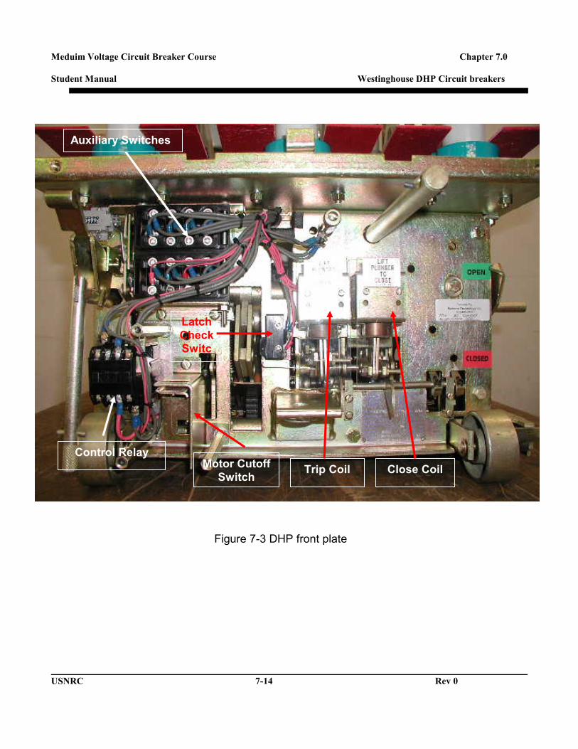
• Auxiliary Switches- they are 2 switches with 4 contacts each (2 N/C and 2 N/O on each switch) stacked together sharing a common actuator linkage. The breaker counter is also grouped with this assembly. These Auxiliary switches provide remote indication of breaker status and a permissive path to the Shunt Trip Coil, allowing the breaker to OPEN electrically. The switch consists of both “A” and “B” contacts. “A” contacts are OPEN when breaker is OPEN and CLOSED when the breaker is CLOSED. “B” contacts do the opposite of “A” contacts. (See Figure 7-3)
• Spring Release and Shunt Trip Coil- The Spring release coil or Close
coil closes the breaker. The Shunt Trip coil opens the breaker. The Close and Trip coils are usually the same physically but can be different control voltage. (See Figure 7-3)
• Control Relay- The Control Relay consists of a solenoid coil, which
actuates 4 sets of contacts; only one set of contacts is used. The Control Relay or Anti-Pump relay prevents the breaker from re-closing if the breaker “TRIPS FREE” and close power is still applied. (See Figure 7-3)
• Motor Cutoff Switch- The MCO switch automatically shuts the Motor
OFF when the Closing Spring is fully charged and provides a permissive path to the close coil when closing springs are CHARGED. (See Figure 7-3)
Meduim Voltage Circuit Breaker Course Chapter 7.0 Student Manual Westinghouse DHP Circuit breakers
USNRC 7-5 Rev 0
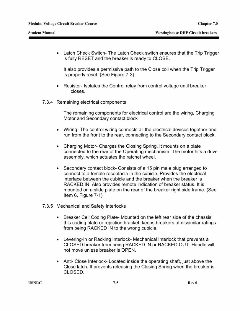
• Latch Check Switch- The Latch Check switch ensures that the Trip Trigger
is fully RESET and the breaker is ready to CLOSE.
It also provides a permissive path to the Close coil when the Trip Trigger is properly reset. (See Figure 7-3)
• Resistor- Isolates the Control relay from control voltage until breaker
closes.
7.3.4 Remaining electrical components
The remaining components for electrical control are the wiring, Charging Motor and Secondary contact block
• Wiring- The control wiring connects all the electrical devices together and
run from the front to the rear, connecting to the Secondary contact block.
• Charging Motor- Charges the Closing Spring. It mounts on a plate connected to the rear of the Operating mechanism. The motor hits a drive assembly, which actuates the ratchet wheel.
• Secondary contact block- Consists of a 15 pin male plug arranged to
connect to a female receptacle in the cubicle. Provides the electrical interface between the cubicle and the breaker when the breaker is RACKED IN. Also provides remote indication of breaker status. It is mounted on a slide plate on the rear of the breaker right side frame. (See Item 6, Figure 7-1)
7.3.5 Mechanical and Safety Interlocks
• Breaker Cell Coding Plate- Mounted on the left rear side of the chassis,
this coding plate or rejection bracket, keeps breakers of dissimilar ratings from being RACKED IN to the wrong cubicle.
• Levering-In or Racking Interlock- Mechanical Interlock that prevents a
CLOSED breaker from being RACKED IN or RACKED OUT. Handle will not move unless breaker is OPEN.
• Anti- Close Interlock- Located inside the operating shaft, just above the
Close latch. It prevents releasing the Closing Spring when the breaker is CLOSED.

Meduim Voltage Circuit Breaker Course Chapter 7.0 Student Manual Westinghouse DHP Circuit breakers
USNRC 7-6 Rev 0
• Floor Tripping and Spring Release Interlock- Mounted to the Operating
Mechanism inside the Front Plate.
• Connected to cams on the front plate just under the Trip and Close Triggers. These interlocks work together to safely DISCHARGE the Closing spring when the breaker is RACKED IN or RACKED OUT by hitting ramps at the bottom of the cubicle.
• Rail Latch- Located on the right front of the chassis, this latch prevents
damage to the Levering-In Screw and the Nut. It also holds the breaker in the TEST position.
• Shutter Roller- Located on the right side of the breaker chassis the
Shutter Roller engages a ramp in the cubicle as the breaker is RACKED IN, lifting the shutter covering the busywork where the breaker Primary Disconnects engage.
7.3.6 Operating Mechanism for the DHP Breaker
• The first generation DHP had a Solenoid Operated Mechanism but there is only one style of Operating Mechanism for the DHP breakers in the Nuclear Industry the Stored Energy Mechanism.
• The Operating Mechanism is the workhorse of the DHP breaker. The
mechanisms contains all the mechanical latches; toggle assemblies, cams, rollers, levers and linkages required to CHARGE, OPEN and CLOSE the breaker. It is connected to the Main contacts via 3 insulated linkages (or Operating Rods) and the Jack bar.
• The Pole Unit Operating shaft is the interface between the Operating
Mechanism and the Primary Contacts. It runs the length of the chassis left to right through levers and bearings. At the right end of the jack bar outside the chassis is MOC switch actuator. This MOC switch actuator provides the OPEN or CLOSED indication on breaker front plate. It also actuates the MOC (Mechanically Operated Contact) switch located in the breaker cubicle providing remote indication that the breaker is OPEN or CLOSED.

Meduim Voltage Circuit Breaker Course Chapter 7.0 Student Manual Westinghouse DHP Circuit breakers
USNRC 7-7 Rev 0
7.3.7 Opening Springs
Depending on the frame size of the breaker there are two designs used on a DHP breaker.
• 4160V Breakers use extension springs located on each end of the
operating shaft and an additional spring on the inside of the front plate. • 7.9KV and 13.8VVA the opening springs are compression springs
connected to the operating shaft. These springs are compressed when the breaker is closed.
• Both style breakers have a kick out spring located between the stationary main contacts. These springs provide an initial push to assist the moving contacts to break free of the stationary contacts.
7.3.8 Puffer Assembly The Puffer assembly is located under the Pole Unit Bases connected to the chassis, running the length of the chassis left to right. Its purpose is to provide a puff of air through the insulating tubes and nozzles to each contact assembly when the breaker is opened.
7.3.9 Levering-In Device • The purpose of the Levering-In device is to move the breaker between
CONNECT and DISCONNECT positions. The main parts are the levering nut, guide tube, levering-in shaft and interlock.
• The Levering-In nut housing also actuates a cubicle switch or TOC (Truck Operated Contact) providing remote indication that the breaker is fully RACKED IN.
7.4 COMMON FAILURE MODES FOR THE DHP BREAKER
Historically, there have been some issues with the DHP breaker in the nuclear industry over the years. There have been several Part 21 Reports issued and a couple of Information Notices.

Meduim Voltage Circuit Breaker Course Chapter 7.0 Student Manual Westinghouse DHP Circuit breakers
USNRC 7-8 Rev 0
7.4.1 NRC bulletins and Information Notices
• Part 21 Report 1998-17-5- the report addresses the anomalies found on 4 different breakers with a similar failure mode. The anomalies were all related to the breaker Auxiliary switches. In particular the auxiliary switch linkage. On two of these breakers the link was bent and on the other two were cracked at the actuator stud. These links were missing the E-Clip retainers as well. It was determined that the link was too long for the intended application. Since the link arm damage would keep the breaker from operating properly it met the criteria for Part 21 Report.
• Part 21 Report 1996-85-1- this report addresses the Motor cutoff
switch and the spring-loaded actuator assembly for the switch. Upon investigation it was found that the Motor Cutoff switch contacts were reading a high resistance. It was also found that the actuator assembly was bound by dirt and excessive friction on the sliding assembly. Since the cutoff switch serves the function of shutting the motor off and provides a permissive close path for breaker operation it was a Part 21 reportable.
• Part 21 Report 1998-71-1- Issued due to the intermittent “Failure to
Close” of a breaker during receipt inspection. It was determined that the Trip Latch gap was not in proper adjustment and ratchet bushing of improper size. The breaker had just been overhauled at a Non-OEM service shop and was one of three that failed receipt inspection. Since the breaker was failing intermittently and it could have been put into service in a safety function, the Part 21 report was issued.
• IN # 96-50- Issued to address the “Failure to Close” of a DHP breaker
because of a worn Levering-In device. The licensee had a false indication that the breaker was fully RACKED IN when it was not. This was due to a worn Levering-In device that had worn key ways and a cracked tube. The licensee Maintenance Procedure did not address the inspection or cleaning of the device. The device was redesigned by the OEM to ensure reliability.
• IN # 98-38- Issued to address general Maintenance and Lubrication
Issues with circuit breakers. At a Nuclear Plant a Westinghouse DHP breaker “Failed to Open” when shutting down a pump. This was the second such failure mode in a 2-week period on the breaker type at the same plant. Teams from the NRC and Licensee assembled to

Meduim Voltage Circuit Breaker Course Chapter 7.0 Student Manual Westinghouse DHP Circuit breakers
USNRC 7-9 Rev 0
determine the cause of the failure.
After the investigation was complete it was determined that improper maintenance and lack of lubrication in key areas were the root cause of the failure.
7.4.2 Other breaker material issues.
• A common failure mode on breakers that have seen little or no
maintenance would be a burnt or OPEN Trip coil. The coil is not the primary cause but could be a symptom of a larger problem. The coil stays energized until the breaker opens and if it doesn’t for any reason, the coil will burn itself out.
• Any device that is external of the breaker frame is vulnerable to damage.
Bent MOC switch actuator, guide rails, covers and trip latch adjusting screws are fairly common.
• The MCO (Motor Cutoff) switch contacts tend to wear down after overtime
and are replaced frequently.
• The most common failure for the DHP is poor maintenance practices.
7.5 MAINTENANCE SCHEDULING FOR THE DHP BREAKER
The Westinghouse Type DHP, like most other breakers of this size, is designed for a lengthy service life with a minimal amount of maintenance. Although the OEM Technical Manual for the DHP doesn’t dictate a specific scheduled maintenance cycle it does offer users several options to fit the application of the breaker to be maintained. Record keeping is a common theme on all options. Time since last inspection, number of cycles and type of load and cycles is another. Record keeping establishes a baseline for future inspections. When the breaker is new the manual strongly recommends a period of no longer than three years since last inspection in any application. The acceptable range for the number of cycles is 2000 to 5000 on average for normal loads.

Meduim Voltage Circuit Breaker Course Chapter 7.0 Student Manual Westinghouse DHP Circuit breakers
USNRC 7-10 Rev 0
7.6 DESIGN UPGRADES FOR THE DHP BREAKER Since the DHP Breaker was first produced in addition to the closing mechanism and the primary pole design changes there have been other minor design changes and modifications to sub components.
• Operating Rod: The original operating rods were a ceramic molding with lead inserts that held the threaded upper portion and the pivot block on the bottom. The newer design is a molded insulating composite with the end metal components as an integral part of the molding.
• Levering-In device: The Levering-In device has also been upgraded. The old style was a racking tube with a single keyway for a couple of rectangular woodruff keys on the racking shaft. This design had a tendency to crack at the front keyway and the woodruff keys would shear. On the newer design, the racking tube has two keyways and the racking shaft has solid groove pins the go completely through the shaft to engage the keyways to improve torque when Levering-In or out.
• Charging Motor: The charging motor has gone through a couple of changes but has the same basic function.
• Motor cut-off switch: The cutoff switch (MCO) has been redesigned with thicker contacts internally to ensure reliability.
• Close and Trip Coil mechanism: The Close and Trip Coils have changed from a plunger type design to a link type design on the newer models.
7.7 LUBRICATION TYPE FOR THE DHP BREAKER
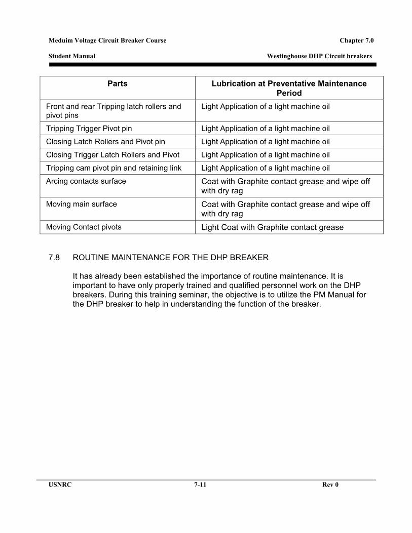
During an overhaul, any non-current carrying part is lubricated with Dow BR-2 Plus grease or Molybdenum Disulphide (Westinghouse # 53701QB). It is a graphite-based lubricant that is dark gray or black in color. It is somewhat fluid grease that adheres well to its components. For the current carrying parts, thick graphite grease, Westinghouse # 53701AN is required. During a PM cycle, light machine oil is recommended for most mechanism parts and petroleum jelly is recommended for current carrying mating surfaces. The following table identifies the location and proper lubricant for each component listed.
Meduim Voltage Circuit Breaker Course Chapter 7.0 Student Manual Westinghouse DHP Circuit breakers
USNRC 7-11 Rev 0
Parts Lubrication at Preventative Maintenance Period
Front and rear Tripping latch rollers and pivot pins
Light Application of a light machine oil
Tripping Trigger Pivot pin Light Application of a light machine oil
Closing Latch Rollers and Pivot pin Light Application of a light machine oil
Closing Trigger Latch Rollers and Pivot Light Application of a light machine oil
Tripping cam pivot pin and retaining link Light Application of a light machine oil
Arcing contacts surface Coat with Graphite contact grease and wipe off with dry rag
Moving main surface Coat with Graphite contact grease and wipe off with dry rag
Moving Contact pivots Light Coat with Graphite contact grease
7.8 ROUTINE MAINTENANCE FOR THE DHP BREAKER
It has already been established the importance of routine maintenance. It is important to have only properly trained and qualified personnel work on the DHP breakers. During this training seminar, the objective is to utilize the PM Manual for the DHP breaker to help in understanding the function of the breaker.

Meduim Voltage Circuit Breaker Course Chapter 7.0 Student Manual Westinghouse DHP Circuit breakers
USNRC 7-12 Rev 0
Figure 7-1 Examples of Monolithic and PIP –DHP Breakers

Meduim Voltage Circuit Breaker Course Chapter 7.0 Student Manual Westinghouse DHP Circuit breakers
USNRC 7-13 Rev 0
Figure 7-2 Contact structure
Moving Contacts
Stationary Contacts
Meduim Voltage Circuit Breaker Course Chapter 7.0 Student Manual Westinghouse DHP Circuit breakers
USNRC 7-14 Rev 0
Figure 7-3 DHP front plate
Auxiliary Switches
Control Relay
Trip Coil Close Coil Motor Cutoff Switch
Latch Check Switc
h