megabolt shear testing program -...
TRANSCRIPT

Megabolt shear testing program
Ron McKenzie
Ben King
Presentation to NUGS and BBUGS 25, 26 Feb 2015
Industry requested information on shear performance of cables in late 2013
Two recognised cable shear testing methods
Double shear test
British Standard (BS 7861-2) double embedment, single shear
Cable shear testing in industry

Costs of outside testing – $10k to $12k per test
Up to 36 different cables
We wanted to control certain variables
Wanted to replicate as close as possible what happens in a coal mine roof
Why do our own testing?
Rock (concrete)strength
Hole diameter
Grout strength
Cable pretension
Friction across the shear plane
Cable types
Embedment length
Factors affecting shear performance

Fixed factors
Rock (concrete)strength Originally 24 MPa
Settled on 40 MPa to align with UoW testing
Hole diameter – 42 mm, rifled holes
Grout strength – 60 MPa – aligns with UNSW pull test program
Friction across the shear plane – test rig designed to minimise effects of friction
Further tests are to be conducted to determine level of friction across the shear planes

Variable factors
Cable pretension
Tests conducted with 0 kN, 90 kN & 250 kN pretension
Cable types
Up to 36 possibilities when wire type, bulbing & cable capacity considered
Embedment length to a lesser degree – depended on the cable being tested
Cable types - wires
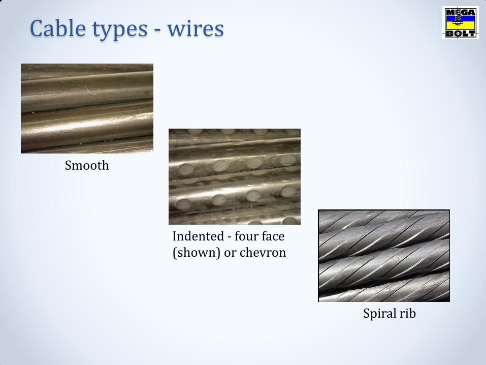
Smooth
Indented - four face (shown) or chevron
Spiral rib
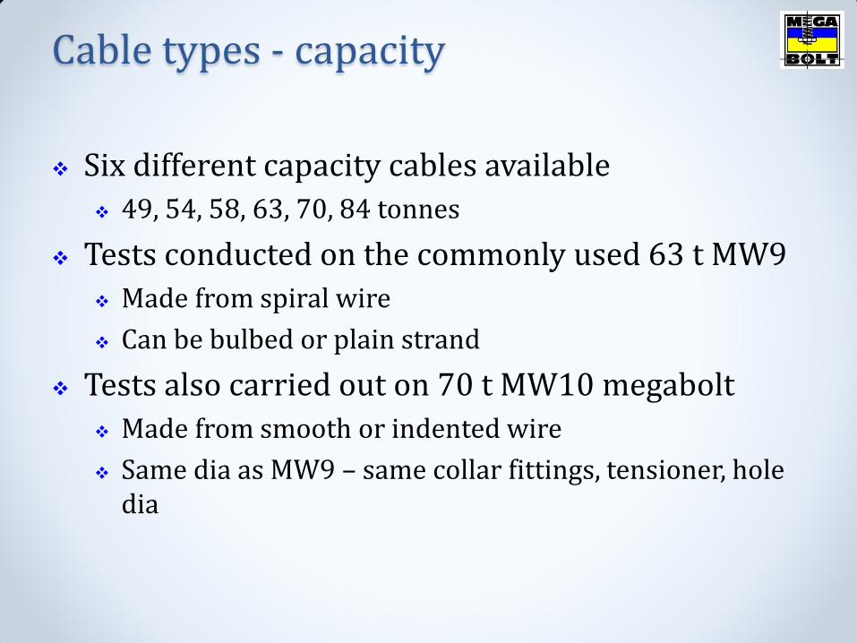
Six different capacity cables available
49, 54, 58, 63, 70, 84 tonnes
Tests conducted on the commonly used 63 t MW9
Made from spiral wire
Can be bulbed or plain strand
Tests also carried out on 70 t MW10 megabolt
Made from smooth or indented wire
Same dia as MW9 – same collar fittings, tensioner, hole dia
Cable types - capacity
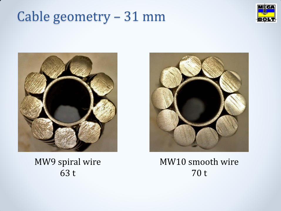
Cable geometry – 31 mm
MW9 spiral wire 63 t
MW10 smooth wire 70 t
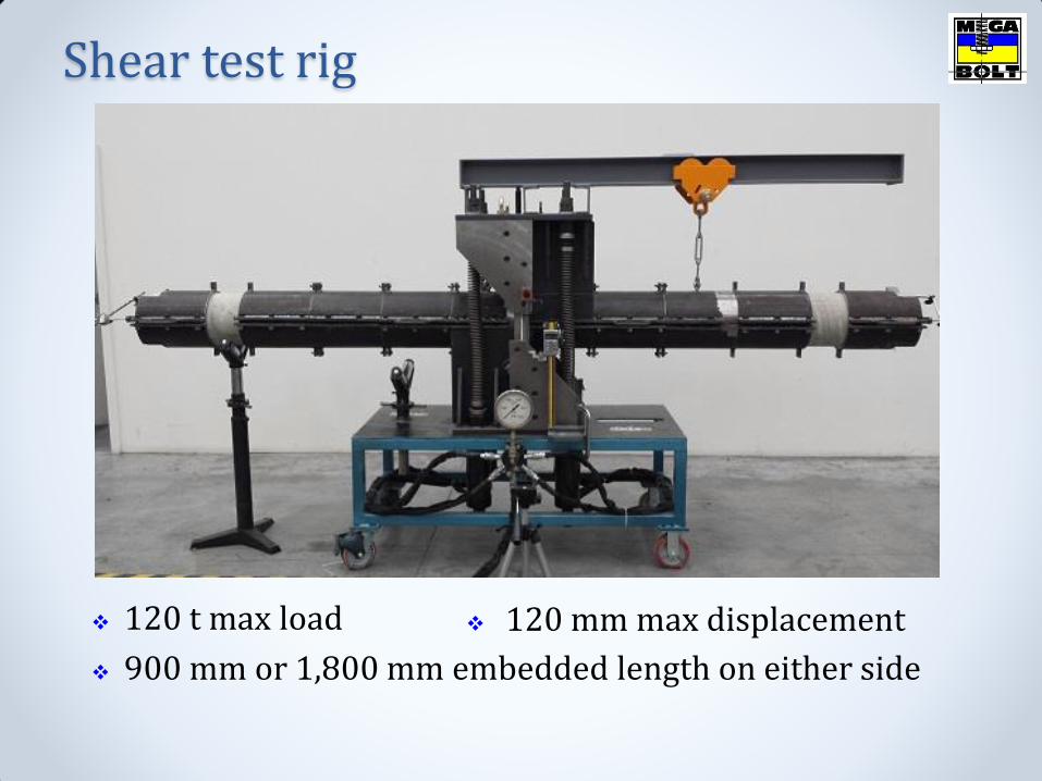
Shear test rig
120 t max load
900 mm or 1,800 mm embedded length on either side
120 mm max displacement

252 mm dia samples
Initial lengths of 900 mm
Increased to 1,800 mm
Sample preparation
Tension applied via frame
No normal force applied across shear plane
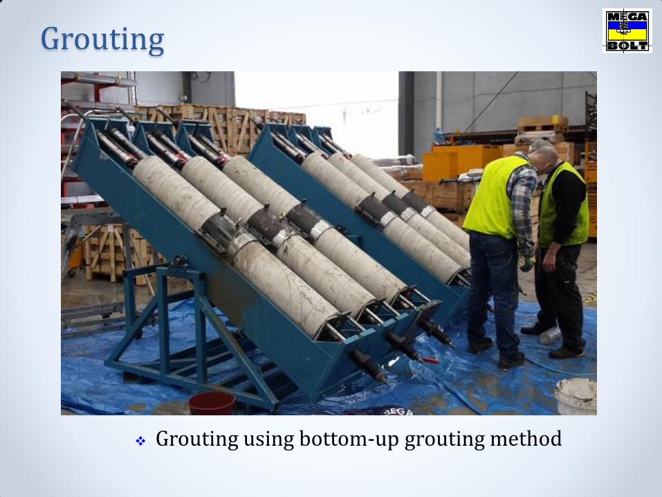
Grouting using bottom-up grouting method
Grouting

Concrete cylinders were confined using cylindrical heavy steel clamps
Prevent radial cracking – in line with UNSW testing
Allows for handling of long lengths
Steel clamps

Friction between the steel faces of the rig is kept to a minimum
Eight roller bearings are the contact points
Friction across faces of the rig
Roller bearings
No pretension load across the shear faces
Concrete cylinders are contained within heavy steel clamps which are secured to faces of the rig – can’t move towards, or away from, the shear plane
Teflon film between faces of the anchor cylinders
Friction across shear faces

This cable pretensioned to 90 kN
Max shear load of 50.4 t
No scoring or signs of frictional wear between faces
Minimising the effects of friction is a major factor in achieving realistic results
Friction across shear faces

As a result of shearing an axial load is applied to the cable in the anchor cylinders
To obtain a realistic shear result the cable should not fully de-bond over the anchor length
The extent of de-bonding is determined by the bond strength of the cable
High bond strength cables have deformed wire & bulbs (MW9) & only require short embedment to fail the cable
When pull tested the standard MW9 will break with 450 mm embedment – hence the reason we started with anchor cylinders 900 mm long
Embedment length

The lower the bond strength the greater the de-bonding of the cable & hence the greater the shear displacement
Effects of bond strength
De-bonding propagates away from shear plane during loading
Displacement
The 900 mm anchor blocks did not provide sufficient embedment for smooth & indented wire cables without bulbs
Complete de-bonding occurred with the cable pulling through the cylinder
Decided to double up the anchor cylinders to provide 1,800 mm embedment
So far there has not been complete de-bonding in the longer anchor cylinders – partial de-bonding will always take place
Embedment length
A number of shear testing programs use end constraints to overcome the problem of full de-bonding along the length of the anchor cylinder or block
End constraints
B&W end constraint on an early test

End constraints do not exist in a mine roof
Exception can be when shearing takes place close to the collar of the cable & then only on one side of the shear plane
Tests on end constraints have shown that B&W draw-in contributes to displacement
Wedges can drawn in up to 16 mm
End constraints
Test Cable Wire Bulbs
per side Embedded
length (mm) Pretension
(kN) Max shear
load (t) Displacement at max load (mm)
1A*^ MW9 Spiral 2 900 90 50.4 94.5
1B MW9 Spiral 2 900 90 40.8 42.9
1C* MW9 Smooth 0 900 90 55.2# 118.6
1D MW9 Spiral 2 900 0 44.4 48.1
1E MW9 Spiral 2 900 250 38.4 34.3
1F* MW10 Smooth 0 900 90 61.2 88.5
1G* MW10 Indented 0 900 90 51.6 80.1
2A MW10 Indented 0 1,800 90 55.2 45.3
2B MW9 Smooth 4 1,800 90 49.2 50.2
2C MW10 Smooth 0 1,800 90 57.0 51.4
* End movement, complete debonding ^ Not fully grouted # Max load, no failure
Results summary

Effects of pre-tension
48 mm, 44 t 43 mm, 41 t
34 mm, 38 t
0
5
10
15
20
25
30
35
40
45
50
55
60
65
0 10 20 30 40 50 60 70 80 90 100 110 120
Shear load (t)
Shear displacement (mm)
MW9 0 kN pretension
MW9 90 kN pretension
MW9 250 kN pretension
Increase in cable tension causes a reduction in the maximum shear load
Also reduces the amount of displacement
Effects of pre-tension
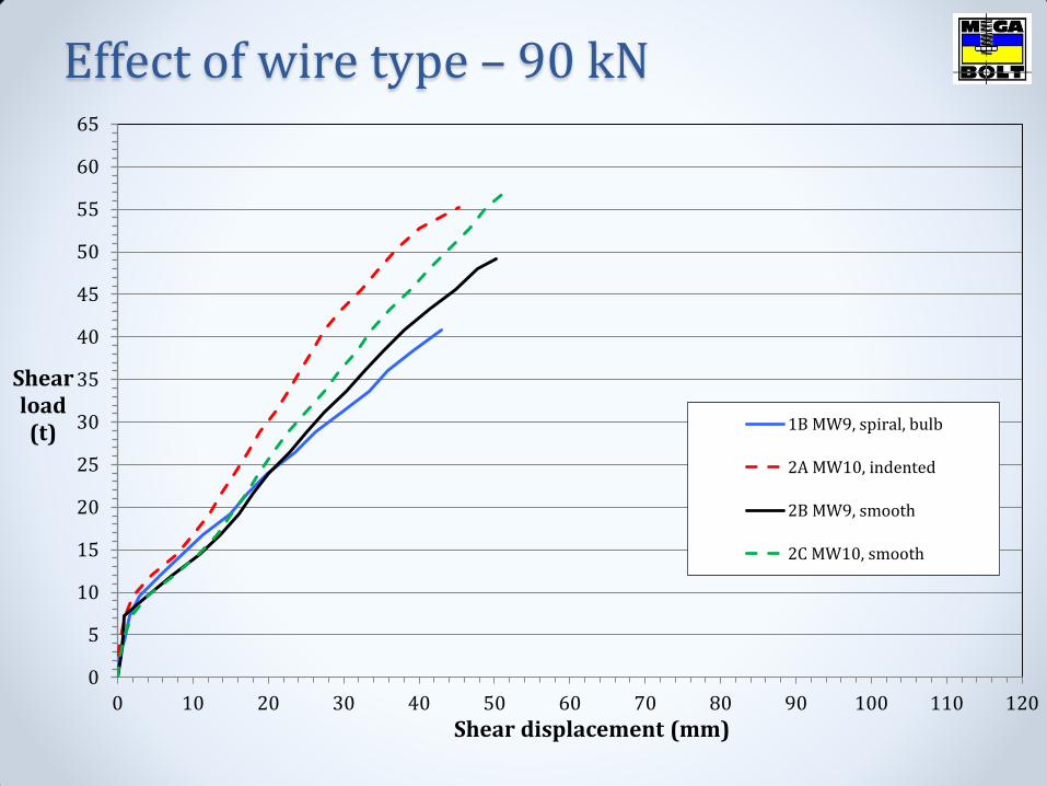
Effect of wire type – 90 kN
0
5
10
15
20
25
30
35
40
45
50
55
60
65
0 10 20 30 40 50 60 70 80 90 100 110 120
Shear load (t)
Shear displacement (mm)
1B MW9, spiral, bulb
2A MW10, indented
2B MW9, smooth
2C MW10, smooth
Smooth wire, and to a lesser extent indented wire, allow for greater shear displacement due to reduced bond strength
Effect of wire type

All results
0
5
10
15
20
25
30
35
40
45
50
55
60
65
0 10 20 30 40 50 60 70 80 90 100 110 120
Shear load (t)
Shear displacement (mm)
1B MW9, spiral, bulb
1C MW9, smooth, no bulb
1D MW9, spiral, bulb, 0 kN
1E MW9, spiral, bulb, 250 kN
1G MW10, indented
2A MW10, indented
2B MW9, smooth
2C MW10, smooth
MW9, not grouted, ends free
Debonded
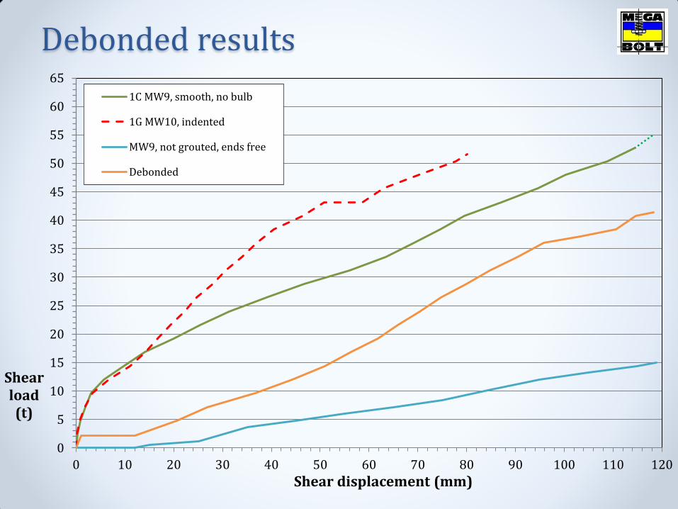
Debonded results
0
5
10
15
20
25
30
35
40
45
50
55
60
65
0 10 20 30 40 50 60 70 80 90 100 110 120
Shear load (t)
Shear displacement (mm)
1C MW9, smooth, no bulb
1G MW10, indented
MW9, not grouted, ends free
Debonded
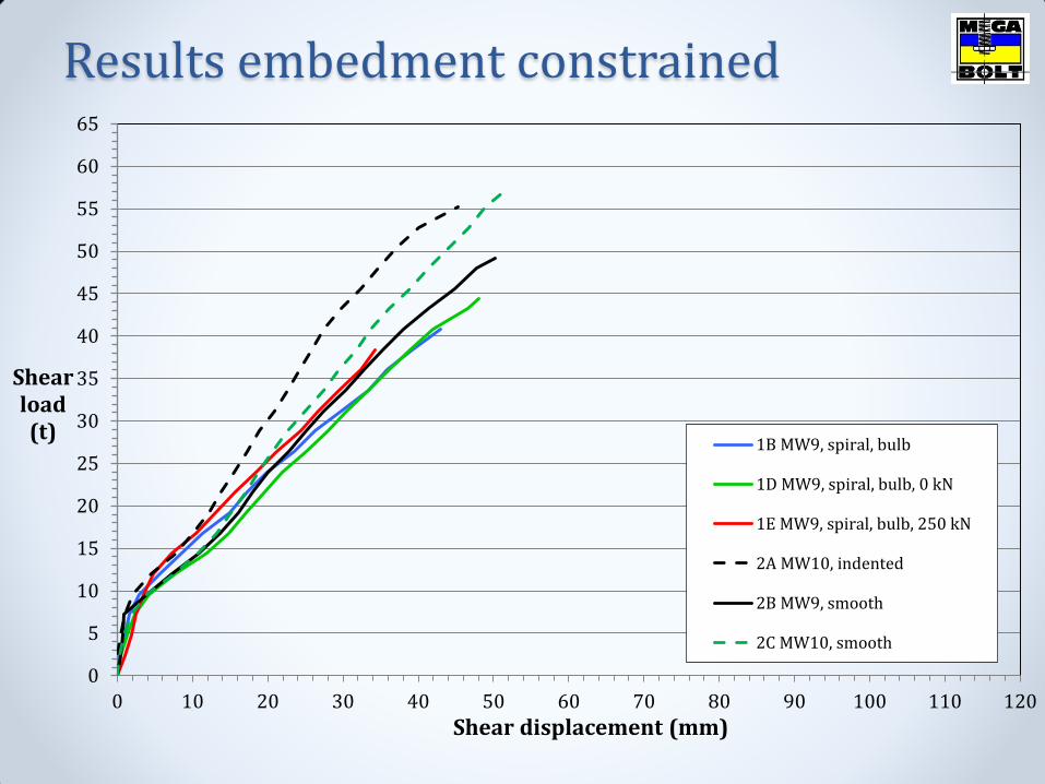
Results embedment constrained
0
5
10
15
20
25
30
35
40
45
50
55
60
65
0 10 20 30 40 50 60 70 80 90 100 110 120
Shear load (t)
Shear displacement (mm)
1B MW9, spiral, bulb
1D MW9, spiral, bulb, 0 kN
1E MW9, spiral, bulb, 250 kN
2A MW10, indented
2B MW9, smooth
2C MW10, smooth
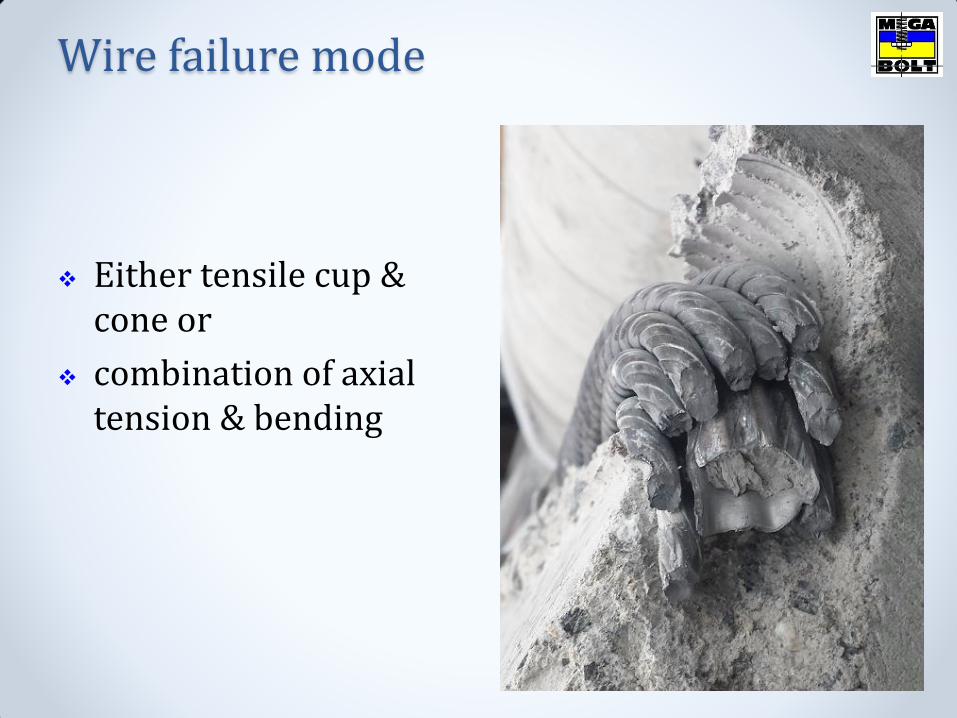
Either tensile cup & cone or
combination of axial tension & bending
Wire failure mode

Shear test on ungrouted, unconstrained MW9
Displacement went to the max of rig – 120 mm
Load was 15 t
Ends of cable progressively bent
Indicates differential loading on wires
Ungrouted, unconstrained test

Wires experience differential strain within the shear zone because of the lay of the wires
This in turn causes sequential failure of the wires
Hence you never reach the max capacity of cable
Ungrouted, unconstrained test
0
5
10
15
20
25
30
35
40
45
0 10 20 30 40 50 60
Shear load (t)
Shear displacement (mm)
The testing program has turned out to be far more involved than originally thought
Further testing is required
Initial results indicate that cable capacity, bond strength and pretension are the most import factors influencing cable shear behaviour
The higher the capacity of the cable the better, the lower the bond strength the better – debonding being the best!
Still require high bond strength in the anchor section at the top of the cable
Conclusions

Thanks for your attention