membrane system user’s manual - water softeners, reverse ... · operation conditions design notes...
TRANSCRIPT

MKTF-358 1 9/14
Membrane System User’s Manual
Model
X1-3280-30

MKTF-358 2 9/14
This page is intentionally left blank

MKTF-358 3 9/14
TABLE OF CONTENTS
INTRODUCTION ................................................................................................................................................... 4
DESIGN PARAMETERS ......................................................................................................................................... 4
SYSTEM INFORMATION ....................................................................................................................................... 5
SYSTEM IDENTIFICATION ..................................................................................................................................... 6
INSTALLATION GUIDELINES ................................................................................................................................. 8
ELECTRICAL .......................................................................................................................................................... 8
PURGING AND INITIAL STARTUP ......................................................................................................................... 9
OPERATING DO’s AND DON’Ts ............................................................................................................................ 9
RO SHUT-DOWN PROCEDURE ............................................................................................................................. 9
OPERATING LOG ................................................................................................................................................ 10
TEMPERATURE CORRECTION SHEET ................................................................................................................. 11
MAINTENANCE .................................................................................................................................................. 12
REPLACING FILTER CARTRIDGES........................................................................................................................ 13
MEMBRANE INSTALLATION, REMOVAL AND REPLACEMENT ........................................................................... 13
MEMBRANE CLEANING ..................................................................................................................................... 16
PREPARING UNIT FOR STORAGE OR SHIPMENT ............................................................................................... 18
TROUBLESHOOTING .......................................................................................................................................... 20
LITERATURE AND DRAWINGS............................................................................................................................ 21
SYSTEM WARRANTY .......................................................................................................................................... 26

MKTF-358 4 9/14
PLEASE READ THE ENTIRE MANUAL BEFORE PROCEEDING WITH THE INSTALLATION AND STARTUP. YOUR FAILURE TO FOLLOW ANY ATTACHED INSTRUCTIONS OR OPERATING PARAMETERS MAY LEAD TO THE PRODUCT’S FAILURE, WHICH CAN CAUSE PROPERTY DAMAGE AND/OR PERSONAL INJURY.
• DO NOT USE WHERE THE WATER IS MICROBIOLOGICALLY UNSAFE OR OF UNKNOWN
QUALITY WITHOUT ADEQUATE DISINFECTION BEFORE OR AFTER THE SYSTEM.
• PRETREATMENT MUST BE SUFFICIENT TO ELIMINATE THE POSSIBILITY OF PREMATURE
FOULING.
• ALWAYS TURN OFF THE UNIT, SHUT OFF THE FEED WATER, AND DISCONNECT THE
ELECTRICAL POWER WHEN WORKING ON THE UNIT.
• NEVER ALLOW THE PUMP TO RUN DRY.
• NEVER START THE PUMP WITH THE CONCENTRATE VALVE CLOSED.
• NEVER ALLOW THE UNIT TO FREEZE OR OPERATE WITH A FEED WATER TEMPERATURE
ABOVE 85°F
INTRODUCTION
The X1-3280-30 is a water purification unit capable of providing 43,200 gallon a day of potable water.
This unit has been designed to reduce contaminants and impurities in the water utilizing Reverse
Osmosis technology. Such water sources are fresh water, chlorinated feed water, and brackish water.
The construction of this unit has been engineered for durability and continuous use.
DESIGN PARAMETERS
Operation Conditions Design Notes
Feed Flow 40
X1-3280 Permeate Flow, GPM 30 Note 1
Concentrate Flow, GPM 10
Permeate to Feed Flow Ratio (Recovery) 75%
Inlet Pressure PSI 30-60
X1-3280 System Pressure PSI 170 Note 2
X1-3280 Concentrate Pressure, PSI 137
Design Temperature, DEG F 50 Note 3
Note 1: Do not exceed recommended permeate flow.

MKTF-358 5 9/14
Note 2: System pressure is variable due to water conditions. Adjust pressure to obtain the correct permeate and
concentrate flows.
Note 3: Permeate flow will increase at a higher temperature.
SYSTEM INFORMATION
System Specifications X1-3280-30
Gallons Per Day (GPD) 43,200
Element Model NF90-400
Number of Elements 6
RO Motor HP 10 HP
System Voltage 220v 3ph
Hertz 60
Feed Line Size 2”
Permeate Line Size 1.5”
Concentrate Line Size 1”
Recycle Line Size 0.75”

MKTF-358 6 9/14
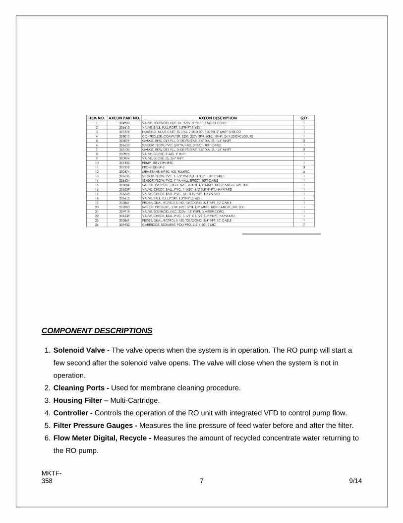
SYSTEM IDENTIFICATION
MKTF-358 7 9/14
COMPONENT DESCRIPTIONS
1. Solenoid Valve - The valve opens when the system is in operation. The RO pump will start a
few second after the solenoid valve opens. The valve will close when the system is not in
operation.
2. Cleaning Ports - Used for membrane cleaning procedure.
3. Housing Filter – Multi-Cartridge.
4. Controller - Controls the operation of the RO unit with integrated VFD to control pump flow.
5. Filter Pressure Gauges - Measures the line pressure of feed water before and after the filter.
6. Flow Meter Digital, Recycle - Measures the amount of recycled concentrate water returning to
the RO pump.

MKTF-358 8 9/14
7. Membrane Pressure Gauges - Measures the pressure at the inlet and outlet of the pressure
vessels.
8. Control Valve - Controls the flow of the concentrate water to the drain. This valve should never
be completely closed when the system is in operation.
9. Recycle Valve - Controls the flow of concentrate being recycled to the inlet of the RO Pump.
10. RO Pump - Pressurizes the incoming water to the design pressure.
11. Membrane Pressure Vessels - Membrane elements housed in fiberglass vessels.
12. Membrane Pressure Vessels - Membrane elements housed in fiberglass vessels.
13. Flow Meter Digital, Permeate - Measures the flow rate of permeate water.
14. Flow Meter Digital, Concentrate - Measures the flow rate of concentrate water.
15. High Pressure Switch - Turns the pump off when the discharge pressure is higher than 300
PSI.
16. Check Valve, Permeate - Prevents back flow in the permeate line.
17. Check Valve, Concentrate - Prevents back flow in the concentrate line.
18. Cleaning Ports - Used for membrane cleaning procedure.
19. TDS Sensors - Measures the quality of feed and permeate.
20. Low Pressure Switch - Turns the pump off when the inlet pressure is lower than 15 PSI.
21. Permeate Flush Solenoid - Helps prolong the life of the membranes.
22. Check Valve – prevents backflow.
23. TDS Sensors - Measures the quality of feed and permeate.
24. Cartridge Filter - 5 micron sediment filter.

MKTF-358 9 9/14
INSTALLATION GUIDELINES
PLUMBING The membranes and high pressure pumps used on X1-Series systems require a continuous flow of water with a minimum feed pressure of 40 psi. Feed, Permeate and Concentrate ports are all labeled. FEED WATER INLET 1. Locate the 2” inlet connection located to the left of the filter housing.
2. Attach the inlet piping to the 2” Solenoid Valve. PERMEATE (PRODUCT WATER) CONNECTION Locate the 1.5” connection labeled permeate and attach to the holding tank. Ensure that the permeate water can flow freely with no backpressure. Backpressure can cause irreversible damage to the membrane elements. The 1.5” permeate line can be run to the holding tank with PVC fittings, or other FDA approved materials. This is so the material being used does not dissolve into the permeate water. CAUTION: THE PH OF THE REVERSE OSMOSIS PERMEATE WATER WILL TYPICALLY BE 1-2 POINTS LOWER THAN THE FEED WATER PH. A LOW PH CAN BE VERY AGGRESSIVE TO SOME PLUMBING MATERIALS SUCH AS COPPER PIPING. CONCENTRATE (WASTE WATER) CONNECTION Locate the 1” connection labeled concentrate and attach to a drain. Run the concentrate line to an open drain in a free and unrestricted manner (no backpressure). CAUTION: ANY RESTRICTIONS OR BLOCKAGE IN THE DRAIN LINE CAN CAUSE BACKPRESSURE, WHICH WILL INCREASE THE SYSTEM’S OPERATING PRESSURE. THIS CAN RESULT IN DAMAGE TO THE SYSTEM’S MEMBRANES AND COMPONENTS.
ELECTRICAL
The X1-3280-30 Reverse Osmosis system is a 220 Volt, 3 Phase, 60 Hertz unit with a Variable Frequency Drive that powers the motor. Must have an independent 30 AMP three phase breaker. Ensure that the electrical circuit supplying the system is compatible with the requirements of the specific X1 model you are installing. Must use a 10 or below gauge rated wire. NOTE: IT’S RECOMMENDED THAT A LICENSED ELECTRICIAN WIRE YOUR SYSTEM IN ACCORDANCE WITH LOCAL AND NATIONAL ELECTRICAL CODES (NEC). WARNING: TO REDUCE THE RISK OF ELECTRICAL SHOCK, THE INCOMING POWER SUPPLY MUST INCLUDE A PROTECTIVE EARTH GROUND.

MKTF-358 10 9/14
PURGING AND INITIAL STARTUP
Direct the permeate water line to drain. 1. Fully open the concentrate valve #8 (counter clockwise) located on the control panel. 2. Fully close the recycle valve #9 (clockwise) located on the control panel if applicable. 3. Press the POWER key #4 to power up the system. 4. Press “Function” Key > “2” key > “Enter” key to initiate manual flush The unit will flush with feed water for 10 minutes (Adjustable). Once the time expires the display screen will say STANDBY.
INITIAL STARTUP
1. Fully open the concentrate valve #8 (counter clockwise) located on the control panel. 2. Fully close the recycle valve #9 (clockwise) located on the control panel if applicable. 3. Press the POWER key #4 to power up the system. 4. Adjust VFD #4, Concentrate #8 and Recycle #9 valve to attain proper flows. The unit will count down for 5 second before turning on the RO Pump. At this time adjust the concentrate valve, recycle valve to obtain the designed flow and pressure. If needed, adjust the hertz in the VFD to increase or decrease the feed flow. Inspect the unit for any possible leaks due to shipment. Once the correct flow is achieved, allow the unit to run for 30 minutes to flush any preservative solution from the unit. After 30 minutes, shut down the system and re-direct the permeate line back to the holding tank. Record the readings daily for a week and after a week record the readings once a week.
OPERATING DO’s AND DON’Ts
DO:
Change the cartridge filters regularly
Monitor the system and keep a daily log
Run the system, as much as possible, on a continuous basis.
Adjust the system recovery to the recommended value
Always feed the pump with filtered water. DON’T:
Permit chlorine to enter or be present in the feed water.
Shut down the system for extended periods.
Close the throttle valve completely.
Operate the system with insufficient feed flow.
Operate the pump dry.

MKTF-358 11 9/14
RO SHUT-DOWN PROCEDURE
1. Press the POWER key. Allow the unit to go through the flush cycle before proceeding to the
next step. 2. Flip the switch to the OFF position on the main branch circuit protection enclosure. (We
recommend every unit should have circuit protection) 3. If the Reverse Osmosis unit is to be shut down for an extended period of time, a membrane
preservative should be used to preserve the membranes. See Preparing Unit for Storage or Shipment.
4. When the unit is ready to restart please follow the initial start up procedures. The permeate line should be diverted to drain for 30 minutes.

MKTF-358 12 9/14
OPERATING LOG

MKTF-358 13 9/14
TEMPERATURE CORRECTION SHEET
Find the temperature correction factor (TCF) from the table below. Divide the rated permeate flow at 77°F by the temperature correction factor. The result is the permeate flow at the desired temperature. See example on the next page.

MKTF-358 14 9/14
TEMPERATURE CORRECTION FORMULA
25 gpm @ 59˚ F (25÷1.42=17.60 gpm)
25 gpm @ 77˚ F (25÷1=25 gpm)
25 gpm @ 84˚ F (25÷0.89=28.08 gpm)
REJECTION FORMULA
The amount of total dissolved solids (TDS) rejected by the membrane is expressed as a percentage. For example, a 99.5% rejection rate means that 99.5% of total dissolved solids do not pass through the membrane. To calculate the % rejection, use the following formula:
% Rejection = [(Feed TDS – Product TDS) / Feed TDS] x 100
99.5% = [(10000-8.25)/10000] x 100 NOTE: ALL TDS FIGURES MUST BE EXPRESSED IN THE SAME UNITS, TYPICALLY PARTS PER MILLION (PPM) OR MILLIGRAMS PER LITER (MG/L).
RECOVERY FORMULA
The amount of permeate water recovered for use is expressed as a percentage. To calculate % recovery, use the following formula:
% Recovery = (Product Water Flow Rate / Feed Water Flow Rate) x 100
75% = (60/80) x 100
NOTE: ALL FLOW RATES MUST BE EXPRESSED IN THE SAME UNITS, TYPICALLY GALLONS PER MINUTE (GPM).
MAINTENANCE
The performance of a Reverse Osmosis Unit is influenced by the feed water composition, feed pressure, temperature and recovery. For example, a feed temperature drop of 4°C will cause a permeate flow decrease of about 10%. This, however, is a normal phenomenon. In order to distinguish between such normal phenomena and performance changes due to fouling or problems, the measured permeate flow and salt passage have to be normalized. Normalization is a comparison of the actual performance to a given reference performance while the influences of operating parameters are taken into account. The reference performance may be the designed performance or the measured initial performance. Normalization with reference to the designed (or warranted) system performance is useful to verify that the plant gives the specified (or warranted) performance. Normalization with reference to the initial system performance is useful to show up any performance changes between day one and the actual date.

MKTF-358 15 9/14
Plant performance normalization is strongly recommended, because it allows an early identification of potential problems (e.g. scaling or fouling) when the normalized data are recorded daily. Corrective measures are much more effective when taken early.
REPLACING FILTER CARTRIDGES
The Reverse Osmosis unit uses 5 micron sediment filter cartridges that need to be replaced frequently.
Change the sediment cartridges when the pressure gauges on the inlet and outlet of the filter housing
indicates a pressure differential of 15 psi.
1. Turn off Reverse Osmosis unit.
2. Open the sample valve on the outlet side of the filter housing to release any pressure.
3. Loosen the V-and clamp and remove carefully.
4. Remove the top of the filter housing.
5. Loosen the two knobs holding the plate in place.
6. Remove the round plate and the spring seals.
7. Remove and discard the old filter cartridges.
8. Install new filter cartridges.
9. Re-assemble the filter housing.
10. Turn on the RO unit and inspect filter housing for leaks.
MEMBRANE INSTALLATION, REMOVAL AND REPLACEMENT
Installation and replacing membranes in the pressure vessels is an easy process if you have the proper information and tools at hand. Please refer to the following instructions when removing and replacing membrane elements:
WARNING: ALL PRESSURE GAUGES MUST READ ZERO BEFORE PROCEEDING. BEFORE ATTEMPTING, DISCONNECT THE POWER FROM THE SYSTEM AND BLEED ALL WATER PRESSURE FROM THE SYSTEM. 1. Turn off the Reverse Osmosis unit.
2. Open the sample valve on each vessel to release any pressure and drain excess water.
3. Remove all necessary PVC piping on the permeate manifold.
4. Remove the retaining ring with the finger pull.
5. Remove the end plugs by pulling carefully from the center of the cap.
6. Remove the end adapter and the old membrane.
7. Use lubricant (Dow 111) to lubricate the brine seal before inserting the membrane.
8. Install the new membrane making sure the brine seal is oriented towards the feed side of the vessel.
9. Re-assemble the end plug and retaining ring.
10. Reconnect all PVC piping that was removed previously.
NOTE: WEAR GLOVES FOR THE FOLLOWING STEPS IN ORDER NOT TO CONTAMINATE THE MEMBRANE. 1. Cut the bag open as close as possible to the seal at one end of the bag, so the bag may be re-
used if necessary.

MKTF-358 16 9/14
2. Make sure that all parts are clean and free from dirt. Examine the brine seal, and permeate tube for nicks or cuts. Replace the O-rings or brine seal if damaged.
3. Flow directions should be observed for installation of the membrane element into the pressure vessels.
REPLACING THE MEMBRANE ELEMENT:
WARNING: THE BRINE SEAL MUST BE IN THE SAME POSITION AS IT WAS FOR FACTORY PRE-INSTALLED MEMBRANE ELEMENT. THE BRINE SEAL IS A RUBBER SEAL THAT PROTRUDES ON ONE SIDE OF THE MEMBRANE AND IS ALWAYS ON THE FEED SIDE OF THE MEMBRANE ELEMENT. 1. Remove membrane elements from the left side if the arrow on the pressure vessels is pointing to
the left and right if arrow is pointing to the right.
2. Lubricate the brine seal and o-rings with a non-petroleum based lubricant, such as Dow Corning® 111. Do not use a petroleum-based lubricant.
3. Carefully install membrane through the membrane housing with brine seal entering last.
4. Re-install the end plug while pushing it onto the housing. Ensure that you do not pinch or fatigue any o-rings while re-installing the end plug. Push the end plug on until the outer diameter of the plug is flush with the retaining ring groove.
5. Insert the retaining ring until they are fully seated.
6. Reconnect any fittings that may have been disconnected when the membrane pressure vessels were disassembled.
7. To Start-Up the system, please refer to the Initial Start-Up section of this manual.
CAUTION: WET MEMBRANES ARE SHIPPED IN A PRESERVATIVE SOLUTION. THE MEMBRANES MUST BE FLUSHED FOR AT LEAST 30 MINUTES TO REMOVE THE PRESERVATIVE FROM THE MEMBRANE. DISCARD ALL OF THE PERMEATE, WHICH IS PRODUCED DURING THE FLUSH PERIOD.
MEMBRANE CLEANING
The surface of a reverse osmosis (RO) membrane is subject to fouling by foreign materials that may be present in the feed water, such as hydrates of metal oxides, calcium precipitates, organics and biological matter. The term “fouling” includes the build-up of all kinds of layers on the membrane surface, including scaling. Pretreatment of the feed water prior to the RO process is basically designed to reduce contamination of the membrane surfaces as much as possible. This is accomplished by installing an adequate pretreatment system and selecting optimum operating conditions, such as permeate flow rate, pressure and permeate water recovery ratio.
MKTF-358 17 9/14
Occasionally, fouling of the membrane surfaces is caused by: • Inadequate pretreatment system • Pretreatment upset conditions • Improper materials selection (pumps, piping, etc.) • Failure of chemical dosing systems • Inadequate flushing following shutdown • Improper operational control • Slow build-up of precipitates over extended periods (barium, silica) • Change in feed water composition • Biological contamination of feed water The fouling of membrane surfaces manifests itself in performance decline; lower permeate flow rate and/or higher solute passage. Increased pressure drop between the feed and concentrate side can be a side effect of fouling. Cleaning can be accomplished very effectively because of the combination of pH stability and
temperature resistance of the membrane and the element components. However, if cleaning is delayed
too long, it could be difficult to remove the foulants completely from the membrane surface. Cleaning will
be more effective the better it is tailored to the specific fouling problem. Sometimes a wrong choice of
cleaning chemicals can make a situation worse. Therefore, the type of foulants on the membrane surface
should be determined prior to cleaning.
Fresh cleaning solution needs to be prepared when the cleaning solution becomes turbid and/or discolored. High-flow recirculation, however, should be carried out separately for each stage, so the flow rate is not too low in the first stage or too high in the last. This can be accomplished either by using one cleaning pump and operating one stage at a time. The fouling or scaling of elements typically consists of a combination of foulants and scalants, for instance a mixture of organic fouling, colloidal fouling and biofouling. Therefore, it is very critical that the first cleaning step is wisely chosen. We strongly recommend alkaline cleaning as the first cleaning step. Acid cleaning should only be applied as the first cleaning step if it is known that only calcium carbonate or iron oxide/hydroxide is present on the membrane elements. Acid cleaners typically react with silica, organics (for instance humic acids) and biofilm present on the membrane surface which may cause a further decline of the membrane performance. Sometimes, an alkaline cleaning may restore this decline that was caused by the acid cleaner. The acid cleaning may be performed when the alkaline cleaning has effectively removed the organic fouling, colloidal fouling and biofouling. Always measure the pH during cleaning. If the pH increases more than 0.5 pH units during acid cleaning, more acid needs to be added. If the pH decreases more than 0.5 pH units during alkaline cleaning, more caustic needs to be added. Long soak times. It is possible for the solution to be fully saturated and the foulants can precipitate back onto the membrane surface. In addition, the temperature will drop during this period, therefore the soaking becomes less effective. It is recommended to circulate the solution regularly in order to maintain the temperature (temperature should not drop more than 5°C) and add chemicals if the pH needs to be adjusted. Turbid or strong colored cleaning solutions should be replaced. The cleaning is repeated with a fresh cleaning solution.

MKTF-358 18 9/14
If the system has to be shut down for more than 24 hours, the elements should be stored in 2% w/w M-100 solution.
PREPARING UNIT FOR STORAGE OR SHIPMENT
Prior to shipping or storing your system, the system should be cleaned with an appropriate cleaner, flushed with water, and protected from biological attack with an appropriate solution for membrane elements. The membrane housing(s) and plumbing lines of the system must be completely drained. Any water remaining in the plumbing of a system may freeze, causing serious damage. Preparing system for storage:
1. Totally immerse the elements in the membrane housing in a solution of 2 % M-100, venting the
air outside of the pressure vessels. Use the overflow technique: circulate the M-100 solution in such a way that the remaining air in the system is minimized after the recirculation is completed. After the pressure vessel is filled, the M-100 solution should be allowed to overflow through an opening located higher than the upper end of the highest pressure vessel being filled.
2. Separate the preservation solution from the air outside by closing all valves. Any contact with
oxygen will oxidize the M-100.
3. Check the pH once a week. When the pH becomes 3 or lower, change the preservation solution.
4. Repeat this process at least once a month.
5. During the shutdown period, the plant must be kept frost-free, or the temperature must not exceed
113°F (45°C).
6. Preparing unit for shipment:
7. Disconnect the inlet, concentrate, pre-filter, and permeate plumbing.
8. Drain all water from the pre-filter cartridge housings by unscrewing the housings, removing the pre-filter cartridges, and drain the water from the housings.
9. Disconnect the tubing from the connectors on the permeate and concentrate inlets and outlets.
10. Fully open the concentrate valve.
11. Drain the flow meters (If applicable)
12. Allow the system to drain for a minimum of eight hours or until the opened ports quit dripping.
13. After draining is complete, reconnect all of the plumbing.

MKTF-358 19 9/14

MKTF-358 20 9/14
TROUBLESHOOTING
SYMPTOMS POSSIBLE CAUSES CORRECTIVE ACTION
Low Inlet Pressure
Low supply pressure Increase Inlet Pressure
Cartridge filters plugged Change Filters
Solenoid valve malfunction Replace Sol. Valve and/or Coil
Motor may not be drawing correct current
Use clamp-on amp meter to check the motor amp draw.
Concentrate valve might be damage
Replace Needle Valve
Leaks Fix any visible leaks
Low Permeate Flow
Low inlet flow Adjust concentrate valve
Cold feed water See temperature correction sheet
Low operating pressure See low inlet pressure
Defective membrane brine seal Inspect & or replace brine seal
Fouled or Scaled membrane Clean membranes
High permeate flow
Damaged product tube o-rings Inspect and/or replace
Damaged or oxidized membrane Replace membrane
Exceeding maximum feed water temperature
See temperature correction sheet
Poor permeate quality
Low operating pressure See low inlet pressure
Damage product tube o-rings Inspect and/or replace
Damaged or oxidized membrane Replace membrane
Membrane fouling
Metal Oxide Fouling Improve pretreatment to remove metals. Clean with Acid Cleaners.
Colloidal Fouling Optimize pretreatment for colloid removal. Clean with high pH anionic cleaners.
Scaling (CaSO4, CaSO3, BaSO4, SiO2)
Increase acid addition and antiscalant dosage for CaVO3 and CaCO4. Reduce recovery. Clean with Acid Cleaners
Biological Fouling
Shock dosage of Sodium Bi-Sulfate. Continuous feed of Sodium Bi-Sulfate at reduced pH. Chlorination and de-chlorination. Replace cartridge filters.
Organic Fouling
Activated Carbon or other pretreatment. Clean with high pH cleaner.
Chlorine Oxidation Check Chlorine feed equipment and de-chlorination system.
Abrasion of membrane by Crystalline Material
Improve pretreatment. Check all filters for media leakage.

MKTF-358 21 9/14
MANUFACTURER’S
LITERATURE & DRAWINGS

MKTF-358 22 9/14
SYSTEM DRAWING

MKTF-358 23 9/14
P&ID
MKTF-358 24 9/14
ELECTRICAL

MKTF-358 25 9/14

MKTF-358 26 9/14
SYSTEM WARRANTY
One-Year Limited Warranty
Warranty Terms Subject to the terms and conditions set forth hereinafter, the Manufacturer (hereafter “Manufacturer”) warrants to the original purchaser (hereafter the “Customer”) that the systems and products manufactured by the Manufacturer are free from defects in material and in workmanship for twelve (12) months from the Warranty Commencement Date (as defined below) only when used strictly in accordance with the applicable operating instructions and within the range of the operating conditions specified by the Manufacturer for each such product. This Warranty does not extend to systems, equipment, or components manufactured by others, nor to systems, equipment, or components manufactured by others and distributed by the Manufacturer. This Warranty does not extend to equipment or components manufactured by others which have been incorporated into a Manufacturer product but, if allowable, Manufacturer hereby assigns, without warranty, to the Customer its interest, if any, under any warranty made by the manufacturer of such equipment or component. This Warranty does not cover disposable items such as fuses, o-rings, regeneration materials/chemicals, or other such disposable items, which must be replaced periodically under the normal and foreseeable operating conditions of the goods warranted hereby. Warranty Commencement Date The Warranty Commencement Date for each Manufacturer product shall be the later of the date of: (1) receipt by the Customer, or (2) the date of installation at the Customer’s premises provided that such installation must occur within three (3) months of shipment from the Manufacturer’s facility. In no event shall the Warranty Commencement Date exceed three (3) months from the shipment from Manufacturer’s facility. The Customer shall provide proof of purchase in order to exercise rights granted under this Warranty. If requested by the Manufacturer, the Customer must also provide proof of the installation date. Proof of installation shall be returned by Customer to the Manufacturer within thirty (30) days after installation by virtue of supplying a Warranty Validation Card supplied with each Manufacturer product fully completed and signed in ink by Customer and the authorized installer of the product. Warranty Service MANUFACTURER’S OBLIGATION UNDER THIS WARRANTY IS LIMITED TO THE REPAIR OR REPLACEMENT (AT MANUFACTURER’S SOLE DISCRETION) OF ANY PRODUCT, OR COMPONENT THEREOF, PROVED TO BE DEFECTIVE IN MATERIAL OR WORKMANSHIP WITHIN THE COVERED WARRANTY PERIOD. The Customer, at the Customer’s risk and expense, shall be responsible for returning such product or component, only after obtaining a Return Goods Authorization (RGA) number from the Manufacturer, arranging for freight prepaid, and in conformance with any special packaging and shipping instructions set forth on the operation documentation or RGA instructions, or as otherwise reasonably required, to the Manufacturer’s address set forth below, together with (1) RGA number issued by the Manufacturer at Customer’s request; (2) proof of purchase and, if necessary, proof of installation date; (3) a Return Goods Authorization Form; (4) a description of the suspected defects; (5) the serial number of the Manufacturer product alleged to be defective; and (6) a description of the type of water and pretreatment equipment which has been utilized in connection with the product, if any. The Manufacturer shall, in the Manufacturer’s reasonable discretion, be the sole judge of whether a returned product or component is defective in material or workmanship. Required or replaced products or components shall be returned surface freight. In genuine emergency situations, the Manufacturer will (at the Manufacturer’s sole discretion) forward replacement parts to Customer without waiting for authorized return of the questionable part(s). In such cases, Customer will issue a purchase order or other payment guarantee prior to shipment. If the returned part is found to have been misused or abused, or the defective part is not received by the Manufacturer within thirty (30) days; the Customer will be invoiced for the replacement part(s) provided. This Warranty does not cover or include labor and/or travel to the Customer’s premise or

MKTF-358 27 9/14
location or any other location. Charges of $1000 per day plus associated travel expenses will be incurred by the Customer in providing the Warranty Service at any location other than the Manufacturer’s main headquarters; that is if the Manufacturer deems that the product is not covered by said Warranty. The Manufacturer reserves the right to precondition such travel to Customer’s premises upon prepayment of the Manufacturer’s anticipated costs of attending such premises. Voidability of Warranty This Warranty shall be void and unenforceable as to any Manufacturer product which has been damaged by accident, mishandling, abuse or has been repaired, modified, altered, disassembled or otherwise tampered with by anyone other than the Manufacturer or an authorized Manufacturer service representative; or, if any replacement parts are not authorized by the Manufacturer have been used, or, the product has not been installed, operated and maintained in strict accordance and adherence with the operating documentation and manuals for such product. Any expressed warranty, or similar representation of performance set forth in the operation documentation for media or resin incorporated into a Manufacturer product shall be void and unenforceable unless the feed water requirements set forth in the operating documentation for such product are unequivocally and strictly adhered to. Limitations and Exclusions THIS WARRANTY AND REMEDIES DESCRIBED HEREIN AND HEREINABOVE ARE EXCLUSIVE AND IN LIEU OF ANY AND ALL OTHER WARRANTY OR REMEDIES, EXPRESSED OR IMPLIED, INCLUDING WITHOUT LIMITATION, ANY IMPLIED WARRANTY OF MERCHANTABILITY OR FITNESS FOR A PARTICULAR PURPOSE. IN NO EVENT SHALL MANUFACTURER BE LIABLE FOR ANY CONSEQUENTIAL, INCIDENTAL OR OTHER SIMILAR TYPES OF DAMAGES, FOR DAMAGES FOR THE LOSS OF PRODUCTION OR PROFITS, OR INJURY TO PERSON OR PROPERTY. NO PERSON HAS ANY AUTHORITY TO BIND MANUFACTURER TO OTHER THAN WHAT IS SET FORTH ABOVE. THIS WARRANTY GIVES THE CUSTOMER SPECIFIC LEGAL RIGHTS AND THE CUSTOMER MAY ALSO HAVE OTHER RIGHTS WHICH VARY FROM JURISDICTION TO JURISDICTION. THE PARTIES RECOGNIZE AND AGREE, THAT IN ALL RESPECTS THE LAWS OF THE STATE OF CALIFORNIA SHALL APPLY TO AND SHALL GOVERN ANY INTERPRETATION OR LEGAL SIGNIFICANCE OF THIS DOCUMENT. NO WARRANTY OR OTHER LIABILITY OF MANUFACTURER TO CUSTOMER UNDER THIS AGREEMENT OR OTHERWISE WILL IN ANY EVENT EXCEED THE COST OF REPLACEMENT OF THE APPLICABLE MANUFACTURER PRODUCT, PART, OR ACCESSORY THAT IS SUBJECT TO ANY BREACH OF MANUFACTURER’S WARRANTY. MANUFACTURER WILL NOT BE LIABLE FOR ANY DAMAGE TO ANY PROPERTY OF CUSTOMER OR TO CUSTOMER’S CUSTOMERS FOR ANY CONSEQUENTIAL, INCIDENTAL, OR ECONOMIC LOSS OR COMMERCIAL DAMAGE WHATSOEVER. REMEDIES HEREIN PROVIDED ARE EXPRESSLY MADE THE SOLE AND EXCLUSIVE REMEDIES FOR BREACH OF ANY WARRANTY OR OTHER OBLIGATION HEREUNDER EXPRESS OR IMPLIED OR FROM THE OPERATION OF LAW.