memory scaling : a systems architecture...
TRANSCRIPT
Memory Scaling: A Systems Architecture Perspective
Onur Mutlu [email protected] May 27, 2013
IMW 2013

The Main Memory System
n Main memory is a critical component of all computing systems: server, mobile, embedded, desktop, sensor
n Main memory system must scale (in size, technology, efficiency, cost, and management algorithms) to maintain performance growth and technology scaling benefits
2
Processor and caches
Main Memory Storage (SSD/HDD)

Memory System: A Shared Resource View
3
Storage

State of the Main Memory System n Recent technology, architecture, and application trends
q lead to new requirements q exacerbate old requirements
n DRAM and memory controllers, as we know them today, are (will be) unlikely to satisfy all requirements
n Some emerging non-volatile memory technologies (e.g., PCM) enable new opportunities: memory+storage merging
n We need to rethink the main memory system q to fix DRAM issues and enable emerging technologies q to satisfy all requirements
4

Agenda
n Major Trends Affecting Main Memory n The DRAM Scaling Problem and Solution Directions
q Tolerating DRAM: New DRAM Architectures q Enabling Emerging Technologies: Hybrid Memory Systems
n How Can We Do Better? n Summary
5

Major Trends Affecting Main Memory (I) n Need for main memory capacity, bandwidth, QoS increasing
n Main memory energy/power is a key system design concern
n DRAM technology scaling is ending
6

Major Trends Affecting Main Memory (II) n Need for main memory capacity, bandwidth, QoS increasing
q Multi-core: increasing number of cores/agents q Data-intensive applications: increasing demand/hunger for data q Consolidation: cloud computing, GPUs, mobile, heterogeneity
n Main memory energy/power is a key system design concern
n DRAM technology scaling is ending
7

Example: The Memory Capacity Gap
n Memory capacity per core expected to drop by 30% every two years n Trends worse for memory bandwidth per core!
8
Core count doubling ~ every 2 years DRAM DIMM capacity doubling ~ every 3 years

Major Trends Affecting Main Memory (III) n Need for main memory capacity, bandwidth, QoS increasing
n Main memory energy/power is a key system design concern
q ~40-50% energy spent in off-chip memory hierarchy [Lefurgy, IEEE Computer 2003]
q DRAM consumes power even when not used (periodic refresh)
n DRAM technology scaling is ending
9

Major Trends Affecting Main Memory (IV) n Need for main memory capacity, bandwidth, QoS increasing
n Main memory energy/power is a key system design concern
n DRAM technology scaling is ending
q ITRS projects DRAM will not scale easily below X nm q Scaling has provided many benefits:
n higher capacity (density), lower cost, lower energy
10

Agenda
n Major Trends Affecting Main Memory n The DRAM Scaling Problem and Solution Directions
q Tolerating DRAM: New DRAM Architectures q Enabling Emerging Technologies: Hybrid Memory Systems
n How Can We Do Better? n Summary
11

The DRAM Scaling Problem n DRAM stores charge in a capacitor (charge-based memory)
q Capacitor must be large enough for reliable sensing q Access transistor should be large enough for low leakage and high
retention time q Scaling beyond 40-35nm (2013) is challenging [ITRS, 2009]
n DRAM capacity, cost, and energy/power hard to scale
12
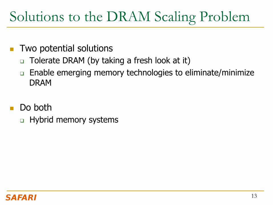
Solutions to the DRAM Scaling Problem
n Two potential solutions q Tolerate DRAM (by taking a fresh look at it) q Enable emerging memory technologies to eliminate/minimize
DRAM
n Do both q Hybrid memory systems
13

Solution 1: Tolerate DRAM n Overcome DRAM shortcomings with
q System-DRAM co-design q Novel DRAM architectures, interface, functions q Better waste management (efficient utilization)
n Key issues to tackle q Reduce refresh energy q Improve bandwidth and latency q Reduce waste q Enable reliability at low cost
n Liu, Jaiyen, Veras, Mutlu, “RAIDR: Retention-Aware Intelligent DRAM Refresh,” ISCA 2012. n Kim, Seshadri, Lee+, “A Case for Exploiting Subarray-Level Parallelism in DRAM,” ISCA 2012. n Lee+, “Tiered-Latency DRAM: A Low Latency and Low Cost DRAM Architecture,” HPCA 2013. n Liu+, “An Experimental Study of Data Retention Behavior in Modern DRAM Devices” ISCA’13.
14

Solution 2: Emerging Memory Technologies n Some emerging resistive memory technologies seem more
scalable than DRAM (and they are non-volatile) n Example: Phase Change Memory
q Expected to scale to 9nm (2022 [ITRS]) q Expected to be denser than DRAM: can store multiple bits/cell
n But, emerging technologies have shortcomings as well q Can they be enabled to replace/augment/surpass DRAM?
n Lee, Ipek, Mutlu, Burger, “Architecting Phase Change Memory as a Scalable DRAM Alternative,” ISCA 2009, CACM 2010, Top Picks 2010.
n Meza, Chang, Yoon, Mutlu, Ranganathan, “Enabling Efficient and Scalable Hybrid Memories,” IEEE Comp. Arch. Letters 2012.
n Yoon, Meza et al., “Row Buffer Locality Aware Caching Policies for Hybrid Memories,” ICCD 2012. n Kultursay+, “Evaluating STT-RAM as an Energy-Efficient Main Memory Alternative,” ISPASS 2013.
15

Hybrid Memory Systems
Meza+, “Enabling Efficient and Scalable Hybrid Memories,” IEEE Comp. Arch. Letters, 2012. Yoon, Meza et al., “Row Buffer Locality Aware Caching Policies for Hybrid Memories,” ICCD 2012 Best Paper Award.
CPU DRAMCtrl
Fast, durable Small,
leaky, volatile, high-cost
Large, non-volatile, low-cost Slow, wears out, high active energy
PCM Ctrl DRAM Phase Change Memory (or Tech. X)
Hardware/software manage data allocation and movement to achieve the best of multiple technologies

Agenda
n Major Trends Affecting Main Memory n The DRAM Scaling Problem and Solution Directions
q Tolerating DRAM: New DRAM Architectures q Enabling Emerging Technologies: Hybrid Memory Systems
n How Can We Do Better? n Summary
17
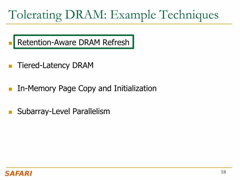
Tolerating DRAM: Example Techniques
n Retention-Aware DRAM Refresh n Tiered-Latency DRAM
n In-Memory Page Copy and Initialization
n Subarray-Level Parallelism
18

DRAM Refresh n DRAM capacitor charge leaks over time
n The memory controller needs to refresh each row periodically to restore charge q Read and close each row every N ms q Typical N = 64 ms
n Downsides of refresh -- Energy consumption: Each refresh consumes energy
-- Performance degradation: DRAM rank/bank unavailable while refreshed
-- QoS/predictability impact: (Long) pause times during refresh -- Refresh rate limits DRAM capacity scaling 19

Refresh Overhead: Performance
20
8%
46%

Refresh Overhead: Energy
21
15%
47%

Retention Time Profile of DRAM
22

RAIDR: Eliminating Unnecessary Refreshes n Observation: Most DRAM rows can be refreshed much less often
without losing data [Kim+, EDL’09]
n Key idea: Refresh rows containing weak cells more frequently, other rows less frequently
1. Profiling: Profile retention time of all rows 2. Binning: Store rows into bins by retention time in memory controller
Efficient storage with Bloom Filters (only 1.25KB for 32GB memory) 3. Refreshing: Memory controller refreshes rows in different bins at different rates
n Results: 8-core, 32GB, SPEC, TPC-C, TPC-H q 74.6% refresh reduction @ 1.25KB storage q ~16%/20% DRAM dynamic/idle power reduction q ~9% performance improvement q Energy benefits increase with DRAM capacity
23 Liu et al., “RAIDR: Retention-Aware Intelligent DRAM Refresh,” ISCA 2012.

Going Forward
n How to find out and expose weak memory cells/rows
n Tolerating cell-to-cell interference at the system level q Flash and DRAM
24

Tolerating DRAM: Example Techniques
n Retention-Aware DRAM Refresh n Tiered-Latency DRAM
n In-Memory Page Copy and Initialization
n Subarray-Level Parallelism
25

26
DRAM Latency-‐Capacity Trend
0
20
40
60
80
100
0.0
0.5
1.0
1.5
2.0
2.5
2000 2003 2006 2008 2011
Latency (ns)
Capa
city (G
b)
Year
Capacity Latency (tRC)
16X
-‐20%
DRAM latency con.nues to be a cri.cal bo4leneck

27
DRAM Latency = Subarray Latency + I/O Latency
What Causes the Long Latency? DRAM Chip
channel
cell array
I/O
DRAM Chip
channel
I/O
subarray
DRAM Latency = Subarray Latency + I/O Latency
Dominant Suba
rray
I/O
28
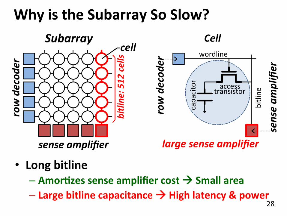
Why is the Subarray So Slow? Subarray
row decod
er
sense amplifier
capacitor
access transistor
wordline
bitline
Cell
large sense amplifier
bitline
: 512 cells cell
• Long bitline – AmorQzes sense amplifier cost à Small area – Large bitline capacitance à High latency & power
sense am
plifier
row decod
er

29
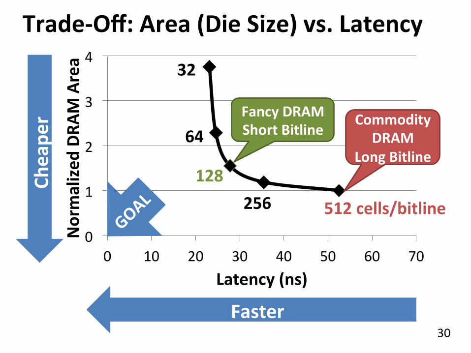
Trade-‐Off: Area (Die Size) vs. Latency
Faster
Smaller
Short Bitline
Long Bitline
Trade-‐Off: Area vs. Latency
30
Trade-‐Off: Area (Die Size) vs. Latency
0
1
2
3
4
0 10 20 30 40 50 60 70
Normalized
DRA
M Area
Latency (ns)
64
32
128 256 512 cells/bitline
Commodity DRAM
Long Bitline
Cheape
r
Faster
Fancy DRAM Short Bitline

31
Short Bitline
Low Latency
ApproximaQng the Best of Both Worlds Long Bitline
Small Area
Long Bitline
Low Latency
Short Bitline Our Proposal Small Area
Short Bitline è Fast Need
IsolaGon Add IsolaGon Transistors
High Latency
Large Area

32
ApproximaQng the Best of Both Worlds
Low Latency
Our Proposal Small Area
Long Bitline Small Area
Long Bitline
High Latency
Short Bitline
Low Latency
Short Bitline Large Area
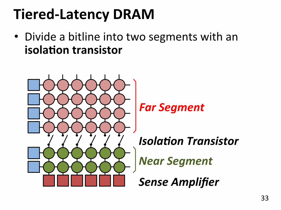
Tiered-‐Latency DRAM
Low Latency
Small area using long bitline
33
Tiered-‐Latency DRAM
Near Segment
Far Segment
IsolaGon Transistor
• Divide a bitline into two segments with an isolaQon transistor
Sense Amplifier

34
0%
50%
100%
150%
0%
50%
100%
150%
Commodity DRAM vs. TL-‐DRAM Latency
Power
–56%
+23%
–51%
+49% • DRAM Latency (tRC) • DRAM Power
• DRAM Area Overhead ~3%: mainly due to the isolaIon transistors
TL-‐DRAM Commodity
DRAM Near Far Commodity
DRAM Near Far TL-‐DRAM
(52.5ns)

35
Trade-‐Off: Area (Die-‐Area) vs. Latency
0
1
2
3
4
0 10 20 30 40 50 60 70
Normalized
DRA
M Area
Latency (ns)
64
32
128 256 512 cells/bitline
Cheape
r
Faster
Near Segment Far Segment

36
Leveraging Tiered-‐Latency DRAM • TL-‐DRAM is a substrate that can be leveraged by the hardware and/or soOware
• Many potenIal uses 1. Use near segment as hardware-‐managed inclusive cache to far segment
2. Use near segment as hardware-‐managed exclusive cache to far segment
3. Profile-‐based page mapping by operaIng system 4. Simply replace DRAM with TL-‐DRAM

37
0%
20%
40%
60%
80%
100%
120%
1 (1-‐ch) 2 (2-‐ch) 4 (4-‐ch) 0%
20%
40%
60%
80%
100%
120%
1 (1-‐ch) 2 (2-‐ch) 4 (4-‐ch)
Performance & Power ConsumpQon 11.5%
Normalized
Perform
ance
Core-‐Count (Channel) Normalized
Pow
er Core-‐Count (Channel)
10.7%
12.4% –23%
–24%
–26%
Using near segment as a cache improves performance and reduces power consumpGon

Tolerating DRAM: Example Techniques
n Retention-Aware DRAM Refresh n Tiered-Latency DRAM
n In-Memory Page Copy and Initialization
n Subarray-Level Parallelism
38

Today’s Memory: Bulk Data Copy
Memory
MC L3 L2 L1 CPU
1) High latency
2) High bandwidth uIlizaIon
3) Cache polluIon
4) Unwanted data movement
39

Future: RowClone (In-‐Memory Copy)
Memory
MC L3 L2 L1 CPU
1) Low latency
2) Low bandwidth uIlizaIon
3) No cache polluIon
4) No unwanted data movement
40

DRAM operation (load one byte)
Row Buffer (4 Kbits)
Memory Bus
Data pins (8 bits)
DRAM array
4 Kbits
1. Activate row
2. Transfer row
3. Transfer byte onto bus

RowClone: in-DRAM Row Copy (and Initialization)
Row Buffer (4 Kbits)
Memory Bus
Data pins (8 bits)
DRAM array
4 Kbits
1. Activate row A
2. Transfer row
3. Activate row B
4. Transfer row

RowClone: Latency and Energy Savings
0
0.2
0.4
0.6
0.8
1
1.2
Latency Energy
Normalized
Savings
Baseline Intra-‐Subarray Inter-‐Bank Inter-‐Subarray
11.5x 74x
43 Seshadri et al., “RowClone: Fast and Efficient In-DRAM Copy and Initialization of Bulk Data,” CMU Tech Report 2013.
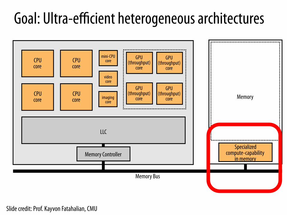
Goal: Ultra-efficient heterogeneous architectures
CPU core
CPU core
CPU core
CPU core
mini-CPU core
video core
GPU (throughput)
core
GPU (throughput)
core
GPU (throughput)
core
GPU (throughput)
core
LLC
Memory Controller Specialized
compute-capability in memory
Memory imaging core
Memory Bus
Slide credit: Prof. Kayvon Fatahalian, CMU

Enabling Ultra-efficient (Visual) Search
▪ What is the right partitioning of computation capability? ▪ What is the right low-cost memory substrate? ▪ What memory technologies are the best enablers? ▪ How do we rethink/ease (visual) search algorithms/applications?
Cache
Processor Core
Memory Bus
Main Memory
Database (of images)
Query vector
Results
Picture credit: Prof. Kayvon Fatahalian, CMU
Tolerating DRAM: Example Techniques
n Retention-Aware DRAM Refresh n Tiered-Latency DRAM
n In-Memory Page Copy and Initialization
n Subarray-Level Parallelism
46

SALP: Reducing DRAM Bank Conflicts n Problem: Bank conflicts are costly for performance and energy
q serialized requests, wasted energy (thrashing of row buffer, busy wait)
n Goal: Reduce bank conflicts without adding more banks (low cost) n Key idea: Exploit the internal subarray structure of a DRAM bank to
parallelize bank conflicts to different subarrays q Slightly modify DRAM bank to reduce subarray-level hardware sharing
n Results on Server, Stream/Random, SPEC q 19% reduction in dynamic DRAM energy q 13% improvement in row hit rate q 17% performance improvement q 0.15% DRAM area overhead
47 Kim, Seshadri+ “A Case for Exploiting Subarray-Level Parallelism in DRAM,” ISCA 2012. 0.0
0.2
0.4
0.6
0.8
1.0
1.2
Nor
mal
ized
D
ynam
ic E
nerg
y
Baseline MASA
-19%
0%
20%
40%
60%
80%
100%
Row
-Buf
fer
Hit
-Rat
e
Baseline MASA
+13
%

Agenda
n Major Trends Affecting Main Memory n The DRAM Scaling Problem and Solution Directions
q Tolerating DRAM: New DRAM Architectures q Enabling Emerging Technologies: Hybrid Memory Systems
n How Can We Do Better? n Summary
48
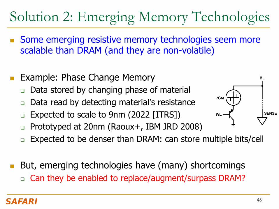
Solution 2: Emerging Memory Technologies n Some emerging resistive memory technologies seem more
scalable than DRAM (and they are non-volatile)
n Example: Phase Change Memory q Data stored by changing phase of material q Data read by detecting material’s resistance q Expected to scale to 9nm (2022 [ITRS]) q Prototyped at 20nm (Raoux+, IBM JRD 2008) q Expected to be denser than DRAM: can store multiple bits/cell
n But, emerging technologies have (many) shortcomings q Can they be enabled to replace/augment/surpass DRAM?
49

Phase Change Memory: Pros and Cons n Pros over DRAM
q Better technology scaling (capacity and cost) q Non volatility q Low idle power (no refresh)
n Cons q Higher latencies: ~4-15x DRAM (especially write) q Higher active energy: ~2-50x DRAM (especially write) q Lower endurance (a cell dies after ~108 writes)
n Challenges in enabling PCM as DRAM replacement/helper: q Mitigate PCM shortcomings q Find the right way to place PCM in the system
50

PCM-based Main Memory (I) n How should PCM-based (main) memory be organized?
n Hybrid PCM+DRAM [Qureshi+ ISCA’09, Dhiman+ DAC’09]: q How to partition/migrate data between PCM and DRAM
51

PCM-based Main Memory (II) n How should PCM-based (main) memory be organized?
n Pure PCM main memory [Lee et al., ISCA’09, Top Picks’10]:
q How to redesign entire hierarchy (and cores) to overcome PCM shortcomings
52

An Initial Study: Replace DRAM with PCM n Lee, Ipek, Mutlu, Burger, “Architecting Phase Change
Memory as a Scalable DRAM Alternative,” ISCA 2009. q Surveyed prototypes from 2003-2008 (e.g. IEDM, VLSI, ISSCC) q Derived “average” PCM parameters for F=90nm
53

Results: Naïve Replacement of DRAM with PCM n Replace DRAM with PCM in a 4-core, 4MB L2 system n PCM organized the same as DRAM: row buffers, banks, peripherals n 1.6x delay, 2.2x energy, 500-hour average lifetime
n Lee, Ipek, Mutlu, Burger, “Architecting Phase Change Memory as a
Scalable DRAM Alternative,” ISCA 2009. 54

Architecting PCM to Mitigate Shortcomings n Idea 1: Use multiple narrow row buffers in each PCM chip
à Reduces array reads/writes à better endurance, latency, energy
n Idea 2: Write into array at cache block or word granularity
à Reduces unnecessary wear
55
DRAM PCM

Results: Architected PCM as Main Memory n 1.2x delay, 1.0x energy, 5.6-year average lifetime n Scaling improves energy, endurance, density
n Caveat 1: Worst-case lifetime is much shorter (no guarantees) n Caveat 2: Intensive applications see large performance and energy hits n Caveat 3: Optimistic PCM parameters?
56

Hybrid Memory Systems
Meza+, “Enabling Efficient and Scalable Hybrid Memories,” IEEE Comp. Arch. Letters, 2012. Yoon, Meza et al., “Row Buffer Locality Aware Caching Policies for Hybrid Memories,” ICCD 2012 Best Paper Award.
CPU DRAMCtrl
Fast, durable Small,
leaky, volatile, high-cost
Large, non-volatile, low-cost Slow, wears out, high active energy
PCM Ctrl DRAM Phase Change Memory (or Tech. X)
Hardware/software manage data allocation and movement to achieve the best of multiple technologies

One Option: DRAM as a Cache for PCM n PCM is main memory; DRAM caches memory rows/blocks
q Benefits: Reduced latency on DRAM cache hit; write filtering
n Memory controller hardware manages the DRAM cache q Benefit: Eliminates system software overhead
n Three issues: q What data should be placed in DRAM versus kept in PCM? q What is the granularity of data movement? q How to design a low-cost hardware-managed DRAM cache?
n Two solutions: q Locality-aware data placement [Yoon+ , ICCD 2012]
q Cheap tag stores and dynamic granularity [Meza+, IEEE CAL 2012]
58

DRAM vs. PCM: An Observation n Row buffers are the same in DRAM and PCM n Row buffer hit latency same in DRAM and PCM n Row buffer miss latency small in DRAM, large in PCM
n Accessing the row buffer in PCM is fast n What incurs high latency is the PCM array access à avoid this
59
CPU DRAMCtrl
PCM Ctrl
Bank Bank Bank Bank
Row buffer DRAM Cache PCM Main Memory
N ns row hit Fast row miss
N ns row hit Slow row miss

Row-Locality-Aware Data Placement n Idea: Cache in DRAM only those rows that
q Frequently cause row buffer conflicts à because row-conflict latency is smaller in DRAM
q Are reused many times à to reduce cache pollution and bandwidth waste
n Simplified rule of thumb: q Streaming accesses: Better to place in PCM q Other accesses (with some reuse): Better to place in DRAM
n Yoon et al., “Row Buffer Locality-Aware Data Placement in Hybrid Memories,” ICCD 2012.
60

Row-Locality-Aware Data Placement: Results
61
0
0.2
0.4
0.6
0.8
1
1.2
1.4
Server Cloud Avg
Nor
mal
ized
Wei
ghte
d Sp
eedu
p
Workload
FREQ FREQ-Dyn RBLA RBLA-Dyn
10% 14% 17%
Memory energy-‐efficiency and fairness also improve correspondingly

0 0.2 0.4 0.6 0.8
1 1.2 1.4 1.6 1.8
2
Weighted Speedup Max. Slowdown Perf. per Watt Normalized Metric
16GB PCM RBLA-Dyn 16GB DRAM
0 0.2 0.4 0.6 0.8
1 1.2 1.4 1.6 1.8
2
Nor
mal
ized
Wei
ghte
d Sp
eedu
p
0
0.2
0.4
0.6
0.8
1
1.2
Nor
mal
ized
Max
. Slo
wdo
wn
Hybrid vs. All-PCM/DRAM
62
31% befer performance than all PCM, within 29% of all DRAM performance
31%
29%

Agenda
n Major Trends Affecting Main Memory n The DRAM Scaling Problem and Solution Directions
q Tolerating DRAM: New DRAM Architectures q Enabling Emerging Technologies: Hybrid Memory Systems
n How Can We Do Better? n Summary
63

Principles (So Far)
n Better cooperation between devices/circuits and the system q Expose more information about devices to upper layers
n Better-than-worst-case design q Do not optimize for worst case q Worst case should not determine the common case
n Heterogeneity in parameters/design q Enables a more efficient design (No one size fits all)
n Need sample chips with main memory interface/speeds q Can enable new designs and applications
64

Other Opportunities with Emerging Technologies
n Merging of memory and storage q e.g., a single interface to manage all data
n New applications q e.g., ultra-fast checkpoint and restore
n More robust system design q e.g., reducing data loss
n Logic in memory? q e.g., enabling efficient search and filtering
65

Agenda
n Major Trends Affecting Main Memory n The DRAM Scaling Problem and Solution Directions
q Tolerating DRAM: New DRAM Architectures q Enabling Emerging Technologies: Hybrid Memory Systems
n How Can We Do Better? n Summary
66

Summary: Main Memory Scaling n Main memory scaling problems are a critical bottleneck for
system performance, efficiency, and usability
n Solution 1: Tolerate DRAM with novel architectures q RAIDR: Retention-aware refresh q TL-DRAM: Tiered-Latency DRAM q RowClone: Fast Page Copy and Initialization
n Solution 2: Enable emerging memory technologies q Replace DRAM with NVM by architecting NVM chips well q Hybrid memory systems with automatic data management
n Software/hardware/device cooperation essential for effective scaling of main memory
67

Thank you.
68

Memory Scaling: A Systems Architecture Perspective
Onur Mutlu [email protected] May 27, 2013
IMW 2013

Backup Slides
70

Backup Slides Agenda
n Building Large DRAM Caches for Hybrid Memories n Memory QoS and Predictable Performance n Subarray-Level Parallelism (SALP) in DRAM
71

Building Large Caches for Hybrid Memories
72

One Option: DRAM as a Cache for PCM n PCM is main memory; DRAM caches memory rows/blocks
q Benefits: Reduced latency on DRAM cache hit; write filtering
n Memory controller hardware manages the DRAM cache q Benefit: Eliminates system software overhead
n Three issues: q What data should be placed in DRAM versus kept in PCM? q What is the granularity of data movement? q How to design a low-cost hardware-managed DRAM cache?
n Two ideas: q Locality-aware data placement [Yoon+ , ICCD 2012]
q Cheap tag stores and dynamic granularity [Meza+, IEEE CAL 2012]
73

The Problem with Large DRAM Caches n A large DRAM cache requires a large metadata (tag +
block-based information) store n How do we design an efficient DRAM cache?
74
DRAM PCM
CPU
(small, fast cache) (high capacity)
Mem Ctlr
Mem Ctlr
LOAD X
Access X
Metadata: X à DRAM
X
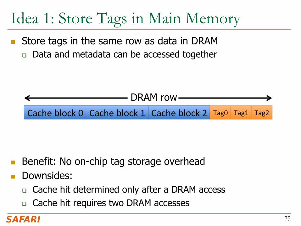
Idea 1: Store Tags in Main Memory n Store tags in the same row as data in DRAM
q Data and metadata can be accessed together
n Benefit: No on-chip tag storage overhead n Downsides:
q Cache hit determined only after a DRAM access q Cache hit requires two DRAM accesses
75
Cache block 2 Cache block 0 Cache block 1 DRAM row
Tag0 Tag1 Tag2

Idea 2: Cache Tags in On-Chip SRAM n Recall Idea 1: Store all metadata in DRAM
q To reduce metadata storage overhead
n Idea 2: Cache in on-chip SRAM frequently-accessed metadata q Cache only a small amount to keep SRAM size small
76

Idea 3: Dynamic Data Transfer Granularity n Some applications benefit from caching more data
q They have good spatial locality
n Others do not q Large granularity wastes bandwidth and reduces cache
utilization
n Idea 3: Simple dynamic caching granularity policy q Cost-benefit analysis to determine best DRAM cache block size
n Meza, Chang, Yoon, Mutlu, Ranganathan, “Enabling Efficient and Scalable Hybrid Memories,” IEEE Comp. Arch. Letters, 2012.
77

0
0.1
0.2
0.3
0.4
0.5
0.6
0.7
0.8
0.9
1
SRAM Region TIM TIMBER TIMBER-‐Dyn
Normalized
Weighted Speedu
p
78
TIMBER Performance
-‐6%
Meza, Chang, Yoon, Mutlu, Ranganathan, “Enabling Efficient and Scalable Hybrid Memories,” IEEE Comp. Arch. Legers, 2012.

0
0.2
0.4
0.6
0.8
1
1.2
SRAM Region TIM TIMBER TIMBER-‐Dyn
Normalized
Perform
ance per W
af
(for M
emory System
)
79
TIMBER Energy Efficiency 18%
Meza, Chang, Yoon, Mutlu, Ranganathan, “Enabling Efficient and Scalable Hybrid Memories,” IEEE Comp. Arch. Legers, 2012.

Hybrid Main Memory: Research Topics n Many research topics from technology
layer to algorithms layer
n Enabling NVM and hybrid memory q How to maximize performance? q How to maximize lifetime? q How to prevent denial of service?
n Exploiting emerging tecnologies q How to exploit non-volatility? q How to minimize energy consumption? q How to minimize cost? q How to exploit NVM on chip?
80
Microarchitecture
ISA
Programs
Algorithms Problems
Logic
Devices
Runtime System (VM, OS, MM)
User
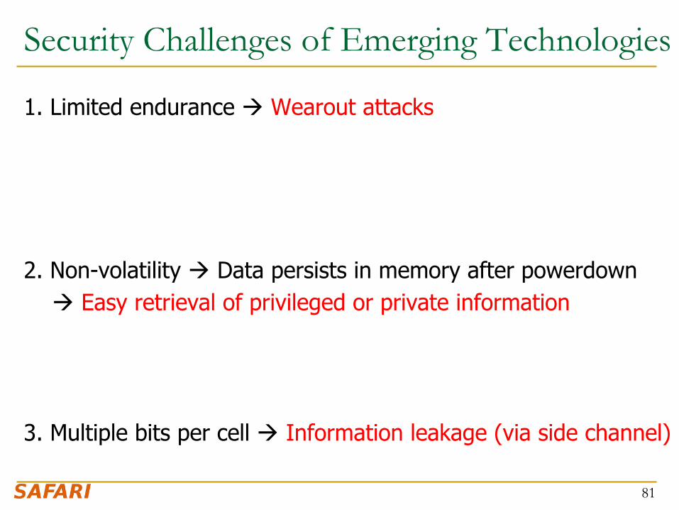
Security Challenges of Emerging Technologies
1. Limited endurance à Wearout attacks 2. Non-volatility à Data persists in memory after powerdown à Easy retrieval of privileged or private information 3. Multiple bits per cell à Information leakage (via side channel)
81
Memory QoS
82

Trend: Many Cores on Chip n Simpler and lower power than a single large core n Large scale parallelism on chip
83
IBM Cell BE 8+1 cores
Intel Core i7 8 cores
Tilera TILE Gx 100 cores, networked
IBM POWER7 8 cores
Intel SCC 48 cores, networked
Nvidia Fermi 448 “cores”
AMD Barcelona 4 cores
Sun Niagara II 8 cores

Many Cores on Chip
n What we want: q N times the system performance with N times the cores
n What do we get today?
84

(Un)expected Slowdowns
Memory Performance Hog Low priority
High priority
(Core 0) (Core 1)
Moscibroda and Mutlu, “Memory performance attacks: Denial of memory service in multi-core systems,” USENIX Security 2007.
Attacker (Core 1)
Movie player (Core 2)
85

Why? Uncontrolled Memory Interference
CORE 1 CORE 2
L2 CACHE
L2 CACHE
DRAM MEMORY CONTROLLER
DRAM Bank 0
DRAM Bank 1
DRAM Bank 2
Shared DRAM Memory System
Multi-Core Chip
unfairness INTERCONNECT
attacker movie player
DRAM Bank 3
86

// initialize large arrays A, B for (j=0; j<N; j++) { index = rand(); A[index] = B[index]; … }
87
A Memory Performance Hog
STREAM
- Sequential memory access - Very high row buffer locality (96% hit rate) - Memory intensive
RANDOM
- Random memory access - Very low row buffer locality (3% hit rate) - Similarly memory intensive
// initialize large arrays A, B for (j=0; j<N; j++) { index = j*linesize; A[index] = B[index]; … }
streaming random
Moscibroda and Mutlu, “Memory Performance Attacks,” USENIX Security 2007.

88
What Does the Memory Hog Do?
Row Buffer
Row
dec
oder
Column mux
Data
Row 0
T0: Row 0
Row 0
T1: Row 16 T0: Row 0 T1: Row 111
T0: Row 0 T0: Row 0 T1: Row 5
T0: Row 0 T0: Row 0 T0: Row 0 T0: Row 0 T0: Row 0
Memory Request Buffer
T0: STREAM T1: RANDOM
Row size: 8KB, cache block size: 64B 128 (8KB/64B) requests of T0 serviced before T1
Moscibroda and Mutlu, “Memory Performance Attacks,” USENIX Security 2007.

Effect of the Memory Performance Hog
0
0.5
1
1.5
2
2.5
3
STREAM RANDOM
89
1.18X slowdown
2.82X slowdown
Results on Intel Pentium D running Windows XP (Similar results for Intel Core Duo and AMD Turion, and on Fedora Linux)
Slow
dow
n
0
0.5
1
1.5
2
2.5
3
STREAM gcc 0
0.5
1
1.5
2
2.5
3
STREAM Virtual PC
Moscibroda and Mutlu, “Memory Performance Attacks,” USENIX Security 2007.

Greater Problem with More Cores
n Vulnerable to denial of service (DoS) [Usenix Security’07]
n Unable to enforce priorities or SLAs [MICRO’07,’10,’11, ISCA’08’11’12, ASPLOS’10]
n Low system performance [IEEE Micro Top Picks ’09,’11a,’11b,’12]
Uncontrollable, unpredictable system
90

Distributed DoS in Networked Multi-Core Systems
91
Attackers (Cores 1-8)
Stock option pricing application (Cores 9-64)
Cores connected via packet-switched routers on chip
~5000X slowdown
Grot, Hestness, Keckler, Mutlu, “Preemptive virtual clock: A Flexible, Efficient, and Cost-effective QOS Scheme for Networks-on-Chip,“ MICRO 2009.

n Problem: Memory interference is uncontrolled à uncontrollable, unpredictable, vulnerable system
n Goal: We need to control it à Design a QoS-aware system
n Solution: Hardware/software cooperative memory QoS q Hardware designed to provide a configurable fairness substrate
n Application-aware memory scheduling, partitioning, throttling
q Software designed to configure the resources to satisfy different QoS goals
q E.g., fair, programmable memory controllers and on-chip networks provide QoS and predictable performance
[2007-2012, Top Picks’09,’11a,’11b,’12]
Solution: QoS-Aware, Predictable Memory

Designing QoS-Aware Memory Systems: Approaches
n Smart resources: Design each shared resource to have a configurable interference control/reduction mechanism q QoS-aware memory controllers [Mutlu+ MICRO’07] [Moscibroda+, Usenix Security’07]
[Mutlu+ ISCA’08, Top Picks’09] [Kim+ HPCA’10] [Kim+ MICRO’10, Top Picks’11] [Ebrahimi+ ISCA’11, MICRO’11] [Ausavarungnirun+, ISCA’12]
q QoS-aware interconnects [Das+ MICRO’09, ISCA’10, Top Picks ’11] [Grot+ MICRO’09, ISCA’11, Top Picks ’12]
q QoS-aware caches
n Dumb resources: Keep each resource free-for-all, but reduce/control interference by injection control or data mapping q Source throttling to control access to memory system [Ebrahimi+ ASPLOS’10,
ISCA’11, TOCS’12] [Ebrahimi+ MICRO’09] [Nychis+ HotNets’10]
q QoS-aware data mapping to memory controllers [Muralidhara+ MICRO’11]
q QoS-aware thread scheduling to cores
93

n Memory Channel Partitioning q Idea: System software maps badly-interfering applications’ pages
to different channels [Muralidhara+, MICRO’11]
n Separate data of low/high intensity and low/high row-locality applications n Especially effective in reducing interference of threads with “medium” and
“heavy” memory intensity q 11% higher performance over existing systems (200 workloads)
A Mechanism to Reduce Memory Interference
94
Core 0 App A
Core 1 App B
Channel 0
Bank 1
Channel 1
Bank 0
Bank 1
Bank 0
Conventional Page Mapping
Time Units
1 2 3 4 5
Channel Partitioning
Core 0 App A
Core 1 App B
Channel 0
Bank 1
Bank 0
Bank 1
Bank 0
Time Units
1 2 3 4 5
Channel 1

Designing QoS-Aware Memory Systems: Approaches
n Smart resources: Design each shared resource to have a configurable interference control/reduction mechanism q QoS-aware memory controllers [Mutlu+ MICRO’07] [Moscibroda+, Usenix Security’07]
[Mutlu+ ISCA’08, Top Picks’09] [Kim+ HPCA’10] [Kim+ MICRO’10, Top Picks’11] [Ebrahimi+ ISCA’11, MICRO’11] [Ausavarungnirun+, ISCA’12]
q QoS-aware interconnects [Das+ MICRO’09, ISCA’10, Top Picks ’11] [Grot+ MICRO’09, ISCA’11, Top Picks ’12]
q QoS-aware caches
n Dumb resources: Keep each resource free-for-all, but reduce/control interference by injection control or data mapping q Source throttling to control access to memory system [Ebrahimi+ ASPLOS’10,
ISCA’11, TOCS’12] [Ebrahimi+ MICRO’09] [Nychis+ HotNets’10]
q QoS-aware data mapping to memory controllers [Muralidhara+ MICRO’11]
q QoS-aware thread scheduling to cores
95
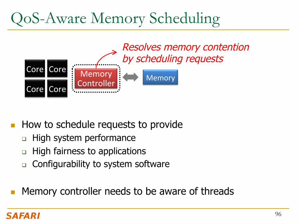
QoS-Aware Memory Scheduling
n How to schedule requests to provide q High system performance q High fairness to applications q Configurability to system software
n Memory controller needs to be aware of threads
96
Memory Controller
Core Core
Core Core Memory
Resolves memory contention by scheduling requests

QoS-Aware Memory Scheduling: Evolution n Stall-time fair memory scheduling [Mutlu+ MICRO’07]
q Idea: Estimate and balance thread slowdowns
q Takeaway: Proportional thread progress improves performance, especially when threads are “heavy” (memory intensive)
n Parallelism-aware batch scheduling [Mutlu+ ISCA’08, Top Picks’09]
q Idea: Rank threads and service in rank order (to preserve bank parallelism); batch requests to prevent starvation
q Takeaway: Preserving within-thread bank-parallelism improves performance; request batching improves fairness
n ATLAS memory scheduler [Kim+ HPCA’10]
q Idea: Prioritize threads that have attained the least service from the memory scheduler
q Takeaway: Prioritizing “light” threads improves performance 97

Take turns accessing memory
Throughput vs. Fairness
98
Fairness biased approach
thread C
thread B
thread A
less memory intensive
higher priority
PrioriIze less memory-‐intensive threads
Throughput biased approach
Good for throughput
starvaGon è unfairness
thread C thread B thread A
Does not starve
not prioriGzed è reduced throughput
Single policy for all threads is insufficient
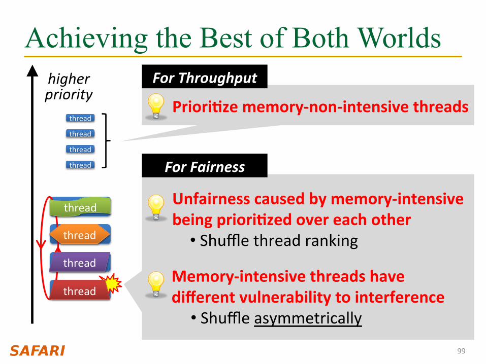
Achieving the Best of Both Worlds
99
thread
thread
higher priority
thread
thread
thread
thread
thread
thread
PrioriQze memory-‐non-‐intensive threads
For Throughput
Unfairness caused by memory-‐intensive being prioriQzed over each other
• Shuffle thread ranking
Memory-‐intensive threads have different vulnerability to interference
• Shuffle asymmetrically
For Fairness
thread
thread
thread
thread

Thread Cluster Memory Scheduling [Kim+ MICRO’10]
1. Group threads into two clusters 2. PrioriQze non-‐intensive cluster 3. Different policies for each cluster
100
thread
Threads in the system
thread
thread
thread
thread
thread
thread
Non-‐intensive cluster
Intensive cluster
thread
thread
thread
Memory-‐non-‐intensive
Memory-‐intensive
PrioriGzed
higher priority
higher priority
Throughput
Fairness
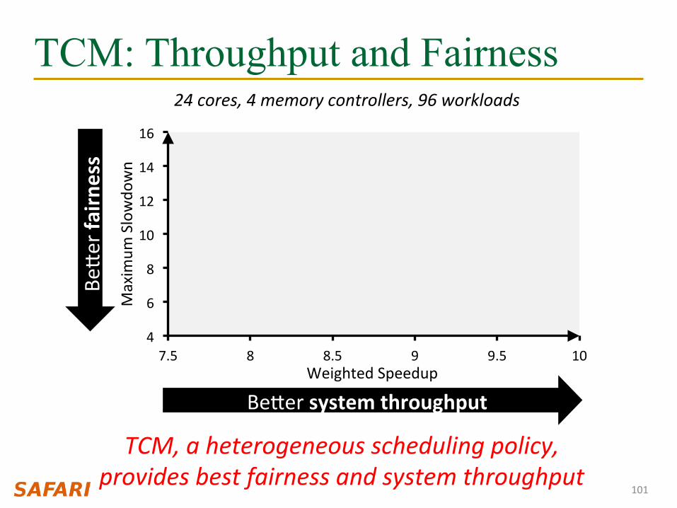
TCM: Throughput and Fairness
FRFCFS
STFM
PAR-‐BS
ATLAS
TCM
4
6
8
10
12
14
16
7.5 8 8.5 9 9.5 10
Maxim
um Slowdo
wn
Weighted Speedup
101
Beger system throughput
Beger fa
irness
24 cores, 4 memory controllers, 96 workloads
TCM, a heterogeneous scheduling policy, provides best fairness and system throughput

TCM: Fairness-Throughput Tradeoff
102
2
4
6
8
10
12
12 12.5 13 13.5 14 14.5 15 15.5 16
Maxim
um Slowdo
wn
Weighted Speedup
When configuraQon parameter is varied…
Adjus.ng ClusterThreshold
TCM allows robust fairness-‐throughput tradeoff
STFM PAR-‐BS
ATLAS
TCM
Beger system throughput
Beger fa
irness FRFCFS

Memory QoS in a Parallel Application
n Threads in a multithreaded application are inter-dependent n Some threads can be on the critical path of execution due
to synchronization; some threads are not n How do we schedule requests of inter-dependent threads to
maximize multithreaded application performance?
n Idea: Estimate limiter threads likely to be on the critical path and prioritize their requests; shuffle priorities of non-limiter threads to reduce memory interference among them [Ebrahimi+, MICRO’11]
n Hardware/software cooperative limiter thread estimation: n Thread executing the most contended critical section n Thread that is falling behind the most in a parallel for loop
103

Summary: Memory QoS Approaches and Techniques
n Approaches: Smart vs. dumb resources q Smart resources: QoS-aware memory scheduling q Dumb resources: Source throttling; channel partitioning q Both approaches are effective in reducing interference q No single best approach for all workloads
n Techniques: Request scheduling, source throttling, memory partitioning q All approaches are effective in reducing interference q Can be applied at different levels: hardware vs. software q No single best technique for all workloads
n Combined approaches and techniques are the most powerful q Integrated Memory Channel Partitioning and Scheduling [MICRO’11]
104

SALP: Reducing DRAM Bank Conflict Impact
105
Kim, Seshadri, Lee, Liu, Mutlu A Case for Exploiting Subarray-Level Parallelism (SALP) in DRAM ISCA 2012.

SALP: Problem, Goal, Observations n Problem: Bank conflicts are costly for performance and energy
q serialized requests, wasted energy (thrashing of row buffer, busy wait) n Goal: Reduce bank conflicts without adding more banks (low cost) n Observation 1: A DRAM bank is divided into subarrays and each
subarray has its own local row buffer
106

SALP: Key Ideas
n Observation 2: Subarrays are mostly independent q Except when sharing global structures to reduce cost
107
Key Idea of SALP: Minimally reduce sharing of global structures
Reduce the sharing of … Global decoder à Enables almost parallel access to subarrays Global row buffer à Utilizes multiple local row buffers

SALP: Reduce Sharing of Global Decoder
108
Local row-buffer
Local row-buffer Global row-buffer
···
Glob
al Decod
er
Latch
Latch
Latch
Instead of a global latch, have per-subarray latches

SALP: Reduce Sharing of Global Row-Buffer
109
Wir
e
Global bitlines
Global row-buffer
Local row-buffer
Local row-buffer
Switch
Switch
READ READ
DD
DD
Selectively connect local row-buffers to global row-buffer using a Designated single-bit latch

SALP: Baseline Bank Organization
110
Local row-buffer
Local row-buffer
Global row-buffer
Glob
al Decod
er
Global bitlines
Latch

SALP: Proposed Bank Organization
111
Local row-buffer
Local row-buffer
Global row-buffer
Glob
al Decod
er
Latch
Latch
D
D
Global bitlines
Overhead of SALP in DRAM chip: 0.15% 1. Global latch à per-subarray local latches 2. Designated bit latches and wire to selectively enable a subarray

SALP: Results n Wide variety of systems with different #channels, banks,
ranks, subarrays n Server, streaming, random-access, SPEC workloads
n Dynamic DRAM energy reduction: 19% q DRAM row hit rate improvement: 13%
n System performance improvement: 17% q Within 3% of ideal (all independent banks)
n DRAM die area overhead: 0.15% q vs. 36% overhead of independent banks
112