merkel sealing technology for injection-molding...
TRANSCRIPT

1
Merkel Sealing Technology for Injection-Molding Applications
MerkelHeavy Industry

2

3
Merkel Sealing Technology
Seals and Sealing Systems for Injection-Molding Applications
Installation recommendations for sealing systems plus descriptions with dimension tables of products used predominantly in injection molding applications
MerkelHeavy Industry

4
5
Leading-edge seal competencein fluidics 4
Typical applicationsSealing systems in injection-molding machines 8
ProductsRod Seals
Merkel U-ring T 20 19Merkel Omegat OMS-MR PR 33Merkel Omegat OMSU-MR PR 41Merkel Omegat OMS-S PR 44Merkel Omegat OMS-S SR 49Merkel Omegat OMS-DR HB 52
Piston SealsMerkel Omegat OMK-MR 57Merkel Omegat OMK-DR HB 65
WipersMerkel Double Wiper PT 1 71 Merkel Double Wiper PT 1-DR HB 66
GuidesMerkel Guide Bush SBK 79Merkel Guide Strip SF 90Merkel Guide Bush KBK 99Merkel Guide Strip KF 110
Rotary SealsSimmerring BAUMSL XL 121
Static SealsMerkel Pinmatic 127Merkel Cover Seal PU 82 131Merkel Cover Seal PU 83 137Merkel Stircomatic SRC 142
Sectoral solutions 144
List of contents
6
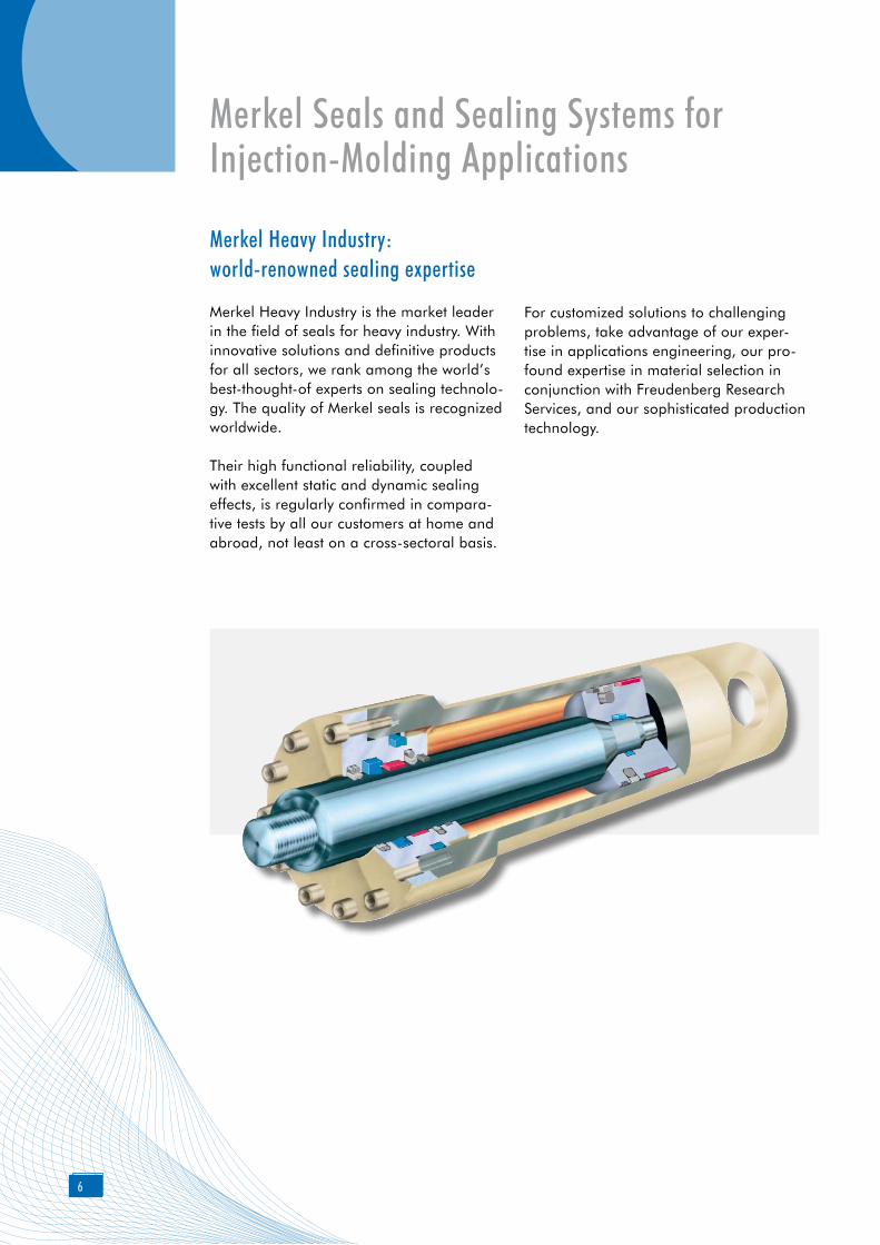
Merkel Seals and Sealing Systems for Injection-Molding Applications
Merkel Heavy Industry:world-renowned sealing expertise
Merkel Heavy Industry is the market leader in the field of seals for heavy industry. With innovative solutions and definitive products for all sectors, we rank among the world’s best-thought-of experts on sealing technolo-gy. The quality of Merkel seals is recognized worldwide.
Their high functional reliability, coupled with excellent static and dynamic sealing effects, is regularly confirmed in compara-tive tests by all our customers at home and abroad, not least on a cross-sectoral basis.
For customized solutions to challenging problems, take advantage of our exper-tise in applications engineering, our pro-found expertise in material selection in conjunction with Freudenberg Research Services, and our sophisticated production technology.
7
Top-class sealing technology for absolutely clean production
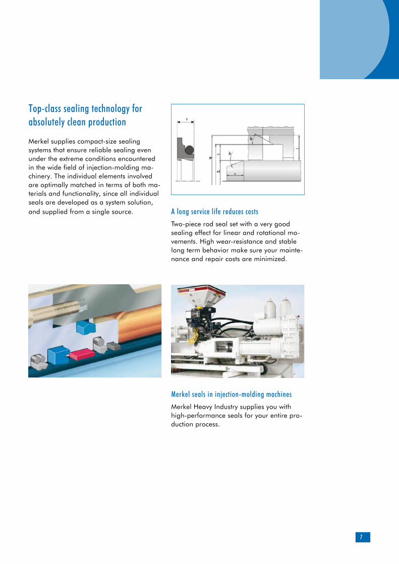
Merkel supplies compact-size sealing systems that ensure reliable sealing even under the extreme conditions encountered in the wide field of injection-molding ma-chinery. The individual elements involved are optimally matched in terms of both ma-terials and functionality, since all individual seals are developed as a system solution, and supplied from a single source. A long service life reduces costs
Two-piece rod seal set with a very good sealing effect for linear and rotational mo-vements. High wear-resistance and stable long term behavior make sure your mainte-nance and repair costs are minimized.
Merkel seals in injection-molding machines
Merkel Heavy Industry supplies you with high-performance seals for your entire pro-duction process.

8
We provide sophisticated, top-quality sealing systems for sealing linear move-ments and radial sealing systems for appli-cations such as:
fast-stroke cylinders pressure pads closing cylinders moving cylinders injection cylinders sealing systems for stroke movement and
combined redating-stroke movement.
Development work is a crucial element in our globally successful product policy.
For example, you will now find at Merkel a new product for toggle-joint machines: with the double-acting compact Merkel Pinmatic seal, you are guaranteed to secure yourself a loss-free, low-maintenance lubricant sup-ply, thus significantly extending the service intervals involved.
Merkel offers you firstly a high level of stock availability from conventional pro-duction methods, and secondly a fast-res-ponse capability for rush repair jobs, based on state-of-the-art lathe technology.
Customized, field-proven, cost-efficient:the best sealing system for every requirement
9
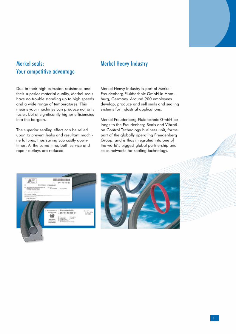
Due to their high extrusion resistance and their superior material quality, Merkel seals have no trouble standing up to high speeds and a wide range of temperatures. This means your machines can produce not only faster, but at significantly higher efficiencies into the bargain.
The superior sealing effect can be relied upon to prevent leaks and resultant machi-ne failures, thus saving you costly down-times. At the same time, both service and repair outlays are reduced.
Merkel Heavy Industry is part of Merkel Freudenberg Fluidtechnic GmbH in Ham-burg, Germany. Around 900 employees develop, produce and sell seals and sealing systems for industrial applications.
Merkel Freudenberg Fluidtechnic GmbH be-longs to the Freudenberg Seals and Vibrati-on Control Technology business unit, forms part of the globally operating Freudenberg Group, and is thus integrated into one of the world’s biggest global partnership and sales networks for sealing technology.
Merkel seals: Your competitive advantage
Merkel Heavy Industry
10
Sealing systems
Typical applications
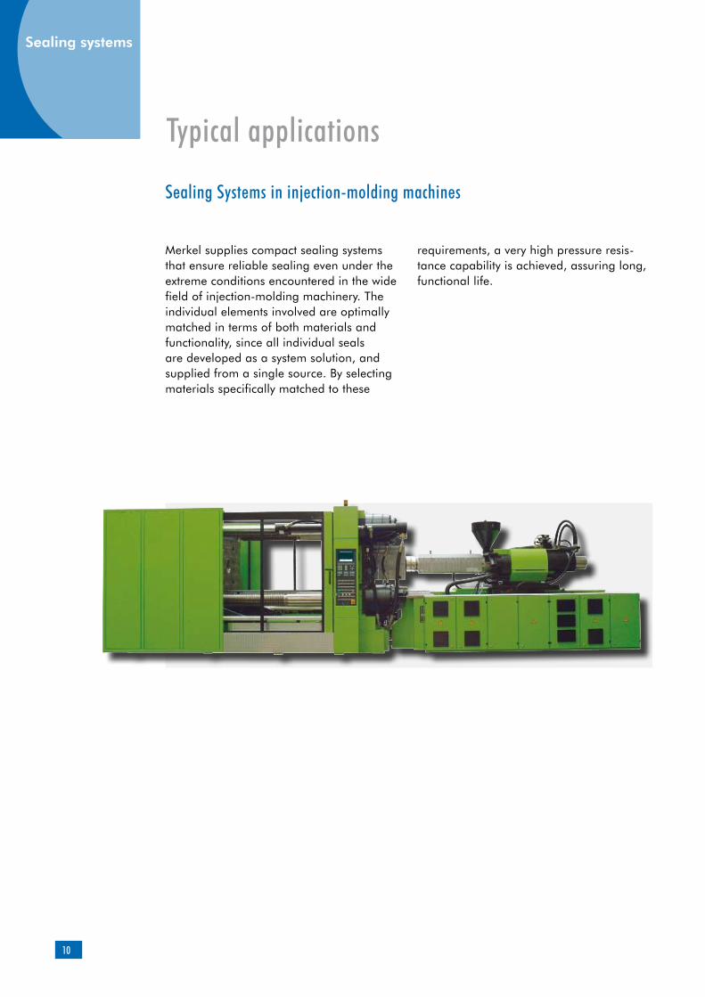
Merkel supplies compact sealing systems that ensure reliable sealing even under the extreme conditions encountered in the wide field of injection-molding machinery. The individual elements involved are optimally matched in terms of both materials and functionality, since all individual seals are developed as a system solution, and supplied from a single source. By selecting materials specifically matched to these
requirements, a very high pressure resis-tance capability is achieved, assuring long, functional life.
Sealing Systems in injection-molding machines
11
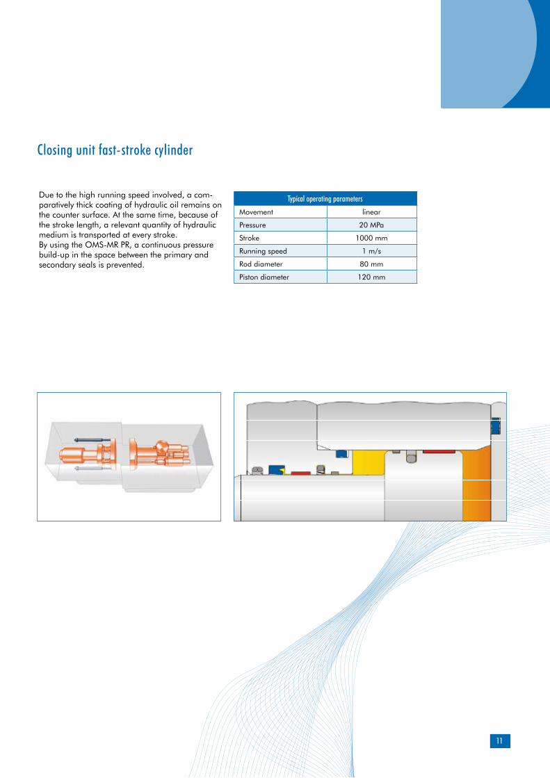
Typical operating parameters
Movement linear
Pressure 20 MPa
Stroke 1000 mm
Running speed 1 m/s
Rod diameter 80 mm
Piston diameter 120 mm
Due to the high running speed involved, a com-paratively thick coating of hydraulic oil remains on the counter surface. At the same time, because of the stroke length, a relevant quantity of hydraulic medium is transported at every stroke.By using the OMS-MR PR, a continuous pressure build-up in the space between the primary and secondary seals is prevented.
Closing unit fast-stroke cylinder
12
Sealing systems
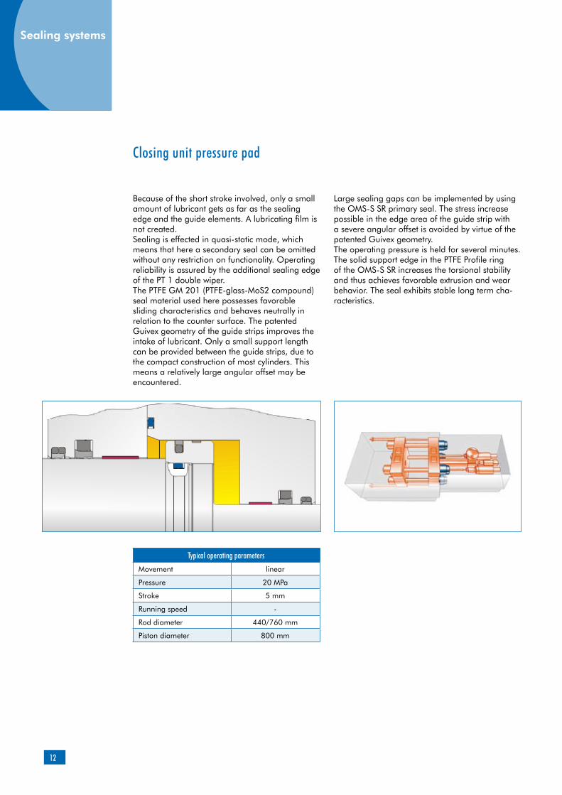
Typical operating parameters
Movement linear
Pressure 20 MPa
Stroke 5 mm
Running speed -
Rod diameter 440/760 mm
Piston diameter 800 mm
Because of the short stroke involved, only a small amount of lubricant gets as far as the sealing edge and the guide elements. A lubricating film is not created.Sealing is effected in quasi-static mode, which means that here a secondary seal can be omitted without any restriction on functionality. Operating reliability is assured by the additional sealing edge of the PT 1 double wiper.The PTFE GM 201 (PTFE-glass-MoS2 compound) seal material used here possesses favorable sliding characteristics and behaves neutrally in relation to the counter surface. The patented Guivex geometry of the guide strips improves the intake of lubricant. Only a small support length can be provided between the guide strips, due to the compact construction of most cylinders. This means a relatively large angular offset may be encountered.
Large sealing gaps can be implemented by using the OMS-S SR primary seal. The stress increase possible in the edge area of the guide strip with a severe angular offset is avoided by virtue of the patented Guivex geometry.The operating pressure is held for several minutes. The solid support edge in the PTFE Profile ring of the OMS-S SR increases the torsional stability and thus achieves favorable extrusion and wear behavior. The seal exhibits stable long term cha-racteristics.
Closing unit pressure pad
13
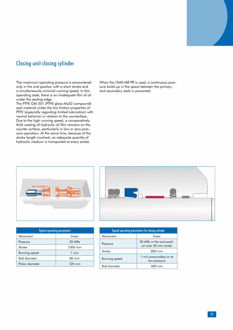
Typical operating parameters
Movement linear
Pressure 20 MPa
Stroke 1000 mm
Running speed 1 m/s
Rod diameter 80 mm
Piston diameter 120 mm
The maximum operating pressure is encountered only in the end position with a short stroke and a simultaneously minimal running speed. In this operating state, there is an inadequate film of oil under the sealing edge.The PTFE GM 201 (PTFE-glass-MoS2 compound) seal material unites the low friction properties of PTFE (especially regarding limited lubrication) with neutral behavior in relation to the counterface.Due to the high running speed, a comparatively thick coating of hydraulic oil film remains on the counter surface, particularly in low or zero pres-sure operation. At the same time, because of the stroke length involved, an adequate quantity of hydraulic medium is transported at every stroke.
When the OMS-MR PR is used, a continuous pres-sure build-up in the space between the primary and secondary seals is prevented.
Closing unit closing cylinder
Typical operating parameters for closing cylinder
Movement linear
Pressure20 MPa in the end positi-
on over 20 mm stroke
Stroke 800 mm
Running speed1 m/s pressureless or at
low pressure
Rod diameter 400 mm
14
Sealing systems
14
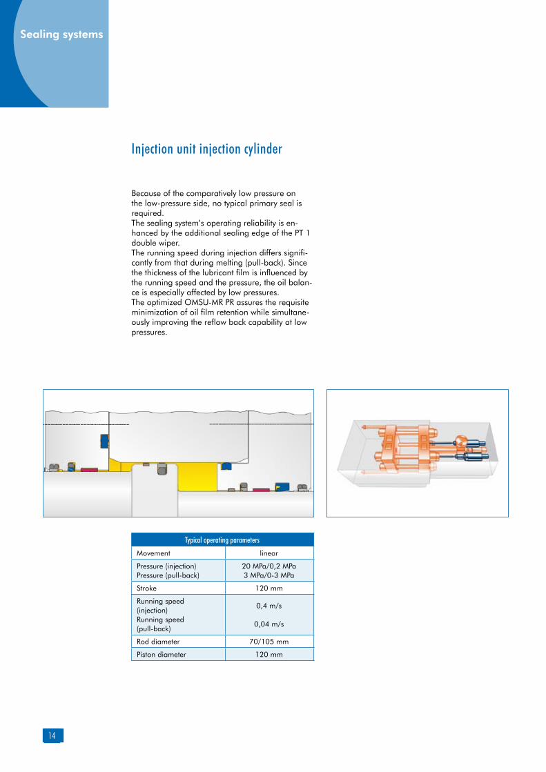
Typical operating parameters
Movement linear
Pressure (injection)Pressure (pull-back)
20 MPa/0,2 MPa3 MPa/0-3 MPa
Stroke 120 mm
Running speed (injection)Running speed (pull-back)
0,4 m/s
0,04 m/s
Rod diameter 70/105 mm
Piston diameter 120 mm
Because of the comparatively low pressure on the low-pressure side, no typical primary seal is required.The sealing system’s operating reliability is en-hanced by the additional sealing edge of the PT 1 double wiper.The running speed during injection differs signifi-cantly from that during melting (pull-back). Since the thickness of the lubricant film is influenced by the running speed and the pressure, the oil balan-ce is especially affected by low pressures.The optimized OMSU-MR PR assures the requisite minimization of oil film retention while simultane-ously improving the reflow back capability at low pressures.
Injection unit injection cylinder
15
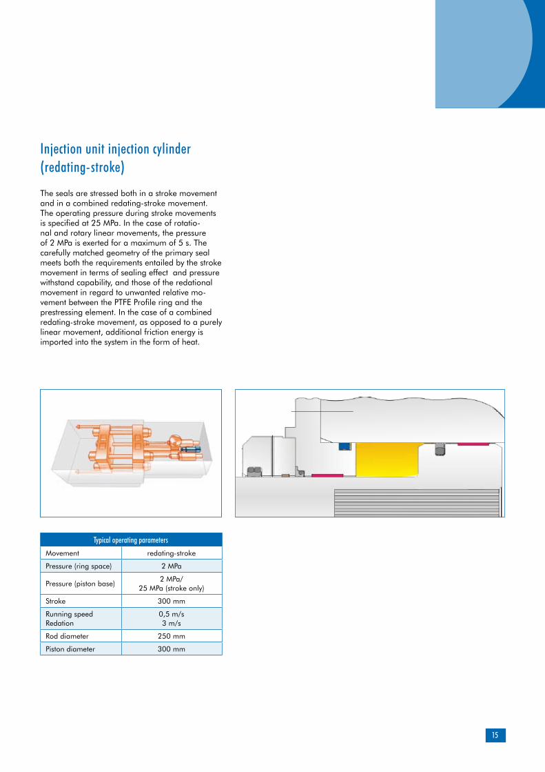
Typical operating parameters
Movement redating-stroke
Pressure (ring space) 2 MPa
Pressure (piston base)2 MPa/
25 MPa (stroke only)
Stroke 300 mm
Running speedRedation
0,5 m/s3 m/s
Rod diameter 250 mm
Piston diameter 300 mm
The seals are stressed both in a stroke movement and in a combined redating-stroke movement. The operating pressure during stroke movements is specified at 25 MPa. In the case of rotatio-nal and rotary linear movements, the pressure of 2 MPa is exerted for a maximum of 5 s. The carefully matched geometry of the primary seal meets both the requirements entailed by the stroke movement in terms of sealing effect and pressure withstand capability, and those of the redational movement in regard to unwanted relative mo-vement between the PTFE Profile ring and the prestressing element. In the case of a combined redating-stroke movement, as opposed to a purely linear movement, additional friction energy is imported into the system in the form of heat.
Injection unit injection cylinder (redating-stroke)

16
Rotary movements sealed up to 2 MPa over short periods of operating pressure in addition to a purely static sealing function up to a pressure of 25 MPa.The Omegat OMS-DR HB makes sure that relative motion will arise exclusively between the slip ring and the sliding surface, even in the event of rotary movements. An appropriate extrusion and wear behavior is also ensured both by the geometrical configuration of the PTFE profile ring and the PTFE compound PTFE C104 (i.e. TFM-PTFE carbon-fiber compound) used here.The BAUMSL X7 Simmerring conceived for pure rotary movements provides, in such an appli-cation, both a wiping edge and an additional sealing edge aimed at retaining the residual oil film. No pressure is applied to the Simmerring.
Injection unit drive end (redating-stroke)
Further applicationsPressure cylinders, ejector cylinders, moving cylin-ders, locking cylinders.In the case of these cylinders, the same sealing systems are used as for fast-stroking cylinders, since the boundary conditions involved are largely similar.
Typical operating parameters
Movement redation
Pressure (redation) 2 MPa
Pressure (static) 25 MPa
Velocity (redation) 3 m/s tmax 5 s
Sealing systems

17
18

19
Material Designation ColorPolyurethane 95 AU V142 dark blue
Polyurethane 94 AU 925 light blue
Product description
Product advantages
extended service life in the sealing system, due to volume compensation functional reliability in the event of radial de-flection due to profile size overlapoperating reliability, due to sturdiness of the polyurethane profile ringhigh sealing effect, due to prominent sealing edge (high line force)secured against metallic contact by high extru-sion resistance (large seal gap)favorable friction values at low pressures due to short contact length (secondary seal)simple and secure installation (single-piece element)
Applications
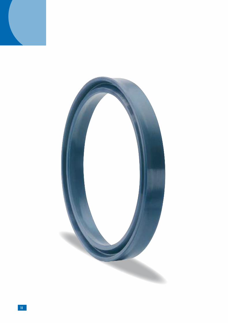
U-ring with asymmetrical profile for sealing piston rods.
Merkel Rod Seal U-Ring T 20
The material is determined by the nominal diameter and the production process involved.
Material
Secondary seal in a sealing systemSingle seal in the pressure range up to 26 MPaSingle seal for subordinate applications in the pressure range up to 40 MPaNominal diameter up to 2,000 mm
Polyurethane profile ring
Asymmetrical sealing lip
The figures given are maximum values and must not be applied simultaneously.
Material 95 AU V142/94 AU 925Hydraulic oils, HL, HLP –30 … +110 °C
HFA fluids +5 … +50 °C
HFB fluids +5 … +50 °C
HFC fluids –30 … +40 °C
HFD fluids –
Water +5 … +40 °C
HETG (rape-seed oil) –30 … +60 °C
HEES (synth. ester) –30 … +60 °C
HEPG (glycol) –30 … +40 °C
Mineral greases –30 … +110 °C
Pressure 40 MPa
Running speed 0,5 m/s*
* When the T 20 is used as a secondary seal, running speed of up to 1.5 m/s can be permitted.
Rod seal
Field of application
20
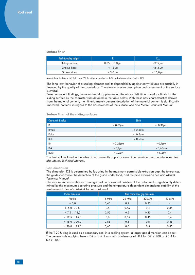
Material content Mr > 50 % to max. 90 %, with cut depth c = Rz/2 and reference line Cref = 0 %
The long term behavior of a sealing element and its dependability against early failures are crucially in-fluenced by the quality of the counterface. Therefore a precise description and assessment of the surface is critical.Based on recent findings, we recommend supplementing the above definition of surface finish for the sliding surface by the characteristics detailed in the table below. With these new characteristics derived from the material content, the hitherto merely general description of the material content is significantly improved, not least in regard to the abrasiveness of the surface. See also Merkel Technical Manual.
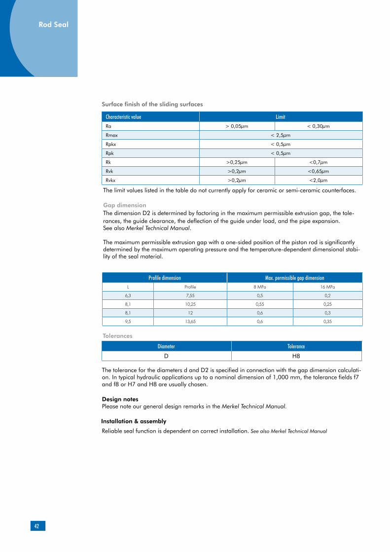
Surface finish of the sliding surfaces
Characteristic value Limit
Ra > 0,05µm < 0,30µm
Rmax < 2,5µm
Rpkx < 0,5µm
Rpk < 0,5µm
Rk >0,25µm <0,7µm
Rvk >0,2µm <0,65µm
Rvkx >0,2µm <2,0µm
The limit values listed in the table do not currently apply for ceramic or semi-ceramic counterfaces. See also Merkel Technical Manual.
Gap dimensionThe dimension D2 is determined by factoring in the maximum permissible extrusion gap, the tolerances, the guide clearance, the deflection of the guide under load, and the pipe expansion See also Merkel Technical Manual. The maximum permissible extrusion gap with a one-sided position of the piston rod is significantly deter-mined by the maximum operating pressure and the temperature-dependent dimensional stability of the seal material. See also Merkel Technical Manual.
Profile dimension Max. permissible gap dimension
Profile 16 MPa 26 MPa 32 MPa 40 MPa
≤ 5,0 0,45 0,4 0,35 -
> 5,0 ... 7,5 0,5 0,45 0,4 0,35
> 7,5 ... 12,5 0,55 0,5 0,45 0,4
> 12,5 ... 15,0 0,6 0,55 0,45 0,4
> 15,0 ... 20,0 0,65 0,6 0,5 0,45
> 20,0 ... 25,0 0,65 0,6 0,5 0,45
Peak-to-valley heights Ra Rmax
Sliding surface 0,05 … 0,3 µm <2,5 µm
Groove base <1,6 µm <6,3 µm
Groove sides <3,0 µm <15,0 µm
Surface finish
If the T 20 U-ring is used as a secondary seal in a sealing system, a larger gap dimension can be set. The general rule applying here is D2 = d + 1 mm with a tolerance of H11 for D2 ≤ 400 or +0.4 for D2 > 400.
Rod seal

21
Tolerances
Diameter D Tolerance
< 400 H11
> 400 +0,4
The tolerance for the diameters d and D2 is specified in connection with the gap dimension calculation. In typical hydraulic applications up to a nominal dimension of 1,000 mm, the tolerance fields f7 and f8 or H7 and H8 are usually chosen.
Installation & assembly
Reliable seal function is dependent on correct installationSee also Merkel Technical Manual.
d D L C
> 320 ... 600 d + 30 25 11
> 320 ... 720 d + 40 32 12
> 720 ... 2000 d + 50 40 16
d D L C
> 320 ... 600 d + 20 16 8
> 600 ... 950 d + 25 20 10
> 950 ... 2000 d + 30 25 11
Housing recommendation for larger diameters (individual seal)
Housing recommendation for larger diameters (secondary seal in a sealing system)
Please note our general design remarks in the Merkel Technical Manual.
Design notesFor U-rings with a nominal dimension of d < 25 mm, an axially accessible housing is required. U-rings with a nominal dimension of d > 25 can generally be installed in a recessed groove using a fitting tool or by hand. Depending on the ratio of the nominal diameter to the Profile dimension, in individual cases an axially accessible housing will be required here as well (note in the article list).

22
Seal configuration
The choice of a sealing element is crucially influenced by the material-dependent resistance to extrusion and the likewise material-dependent friction and wear behaviors.The values of the principal characteristics (sealing effect, dimensional stability and friction or wear) are mutually contradictory in this context.Depending on the operating and boundary condi-tions involved, U-rings made of Polyurethane are used as individual seals, but more frequently in an appropriate combination of individual sealing and guide elements as a secondary seal in a sealing system.
The characteristics of the individual elements in a sealing system are optimized in line with the principal requirement involved. An individual seal, or the primary seal in the system concerned, is exposed to the operating pressure. The principal requirement being high resistance to extrusion coupled with favorable frictional values under high pressure. The secondary seal in a sealing system is exposed to the low intermediate space pressure. The principal requirements in this case are the effective reduction of the residual-oil film relea-sed via the primary seal, coupled with favorable frictional values at low pressures.
Mold-release volume
In a sealing system, the space between the pri-mary and secondary seals is filled with hydraulic medium after a few cycles. The further entry of media leads to an increase of the pressure in the intermediate space. If a U-ring is used as the secondary seal, then it will act as a volume com-pensator under pressure by reason of the mold-
release volume (Fig. 01). The pressure level in the intermediate space, and thus the thermal and mechanical loads as well, are effectively reduced.
Sealing effect
An element’s sealing effect is described in terms of the ratio between the wiping effect and the return capability.
The initial sealing effect of compact, two-piece sealing elements is achieved by pressing the pre-stressing element. There is thus, of course, a close interdependence between the deformation of the loading element and the force being applied. A small change in the compression (due to tole-rances and radial movement) results in a rele-vant change in the force being applied and thus ultimately in the sealing effect. In the case of the T 20 U-ring, the initial sealing effect is entailed by the deformation of the sealing lips. Small changes in the radial contact pressure do not produce any relevant change in the pressure exerted by the sealing edge. The U-ring’s geometry is thus, at a consistently high level of functionality, tolerant to radial deflections.
In the high-pressure range, many sealing ele-ments exhibit a satisfactory sealing effect, attri-butable solely to the high contact pressure on the counterface. In the pressure range up to 5 MPa (intermediate space pressure in the sealing system), by contrast, the sealing effect is crucially influenced by the edge geometry and the contact stress. The compression characteristic under the sealing edge is generally optimized so as to ensu-re effective wiping ability in the pressure chamber (rapid pressure rise) and a good return capability from the back (slow pressure rise). (See Fig. 02)
Additional product description for U-ring T 20
Fig. 01
Merkel U-ring T 20 at 0 MPa Merkel U-ring T 20 at 20 MPa
Rod seal

23
In comparison to compact sealing elements, the U-ring geometry of the T 20 exhibits a short contact length at low pressure, with a definite pressing maximum value. The oil film is effectively downsized here, all that remains is the wetting on the counterface, desirable in terms of the sliding characteristics.
Friction
With sealing elements made of polyurethane, the material properties mean that a high sealing effect is achieved. Depending on the force being applied and the size of the contact area, the seal material is intermeshed to a greater or lesser extent with the counterface. The closer the contact, the higher the friction force will be. Due to the small contact length of a PU U-ring in the low-pressure range, significantly lower friction values are achieved in comparison to compact sealing elements made of polyurethane.As the secondary seal in a sealing system, the T 20 U-ring is subjected to significantly less than the mold-release pressure. If, however, the U-ring is being used as an individual seal, the operating pressure may rise to a level above the U-ring’s mold-release pressure. Because of the increased intermeshing between the seal material and the counter surfacedue to the enlarged contact area, the amount of friction rises. If the working pres-sure is between 5 MPa and 10 MPa, the friction-optimized version LF 300 (LF = “low friction”) with a grooved contact surface is the preferable option.
Extrusion
The resistance to extrusion is essentially deter-mined by the properties of the seal materials. In addition, not only the size of the deformation, but the deformation volume available also plays a crucial role. Due to the generally larger volume provided by a U-ring, larger gaps can be per-mitted here under otherwise identical boundary conditions in comparison to a compact seal with a slip ring made of Polyurethane. This significant-ly reduces the possibility of unwanted metallic contacts.
The sealing system’s service life is extended by using the T 20 U-ring in the sealing system concerned, since as a volume compensator it substantially reduces the thermal and mechani-cal stresses involved, thus assuring stable long term behavior.
Due to a U-ring’s larger deformation volume, larger gaps can be permitted, thus significantly reducing the possibility of metallic contacts.
The T 20 U-ring exhibits an edge geometry designed for optimum sealing effect. Individual seals and sealing systems with a T 20 U-ring as the secondary seal score highly in terms of a very good sealing effect.
Fig. 02: Contact stress p and contact height h for the T 20 U-ring, extending rod at 0.5 MPa operating pressure, 0.28 m/s velocity

24
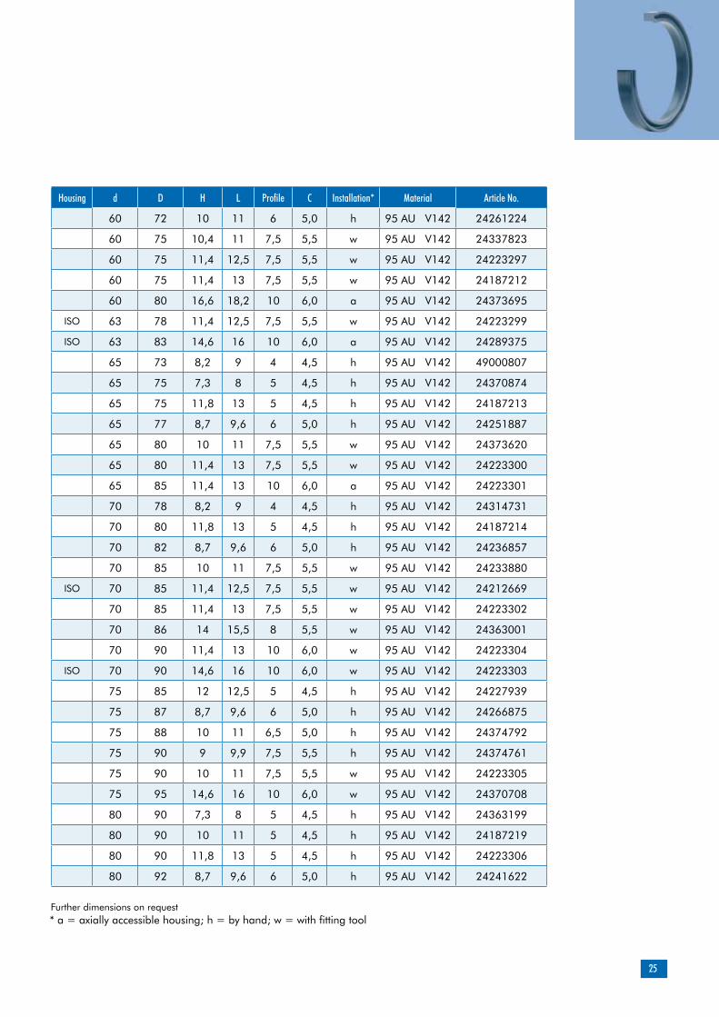
Housing d D H L Profile C Installation* Material Article No.
50 58 8 9 4 4,5 h 95 AU V142 24290848
50 58 8,2 9 4 4,0 h 95 AU V142 24223250
ISO 50 60 7,3 8 5 4,5 h 95 AU V142 24223251
50 60 10 11 5 4,5 h 95 AU V142 24187205
50 62 10 11 6 5,0 w 95 AU V142 24223289
50 65 10 11 7,5 5,5 w 95 AU V142 24187206
ISO 50 65 11,4 12,5 7,5 5,5 w 95 AU V142 24223290
50 70 11,4 13 10 6,0 a 95 AU V142 24223291
55 63 7,3 8 4 4,5 h 95 AU V142 24236859
55 63 8 9 4 4,5 h 95 AU V142 24290846
55 63 8,2 9 4 4,5 h 95 AU V142 24223292
55 65 7,3 8 5 4,5 h 95 AU V142 24239429
55 65 10 11 5 4,5 h 95 AU V142 24187207
55 65 11,8 13 5 4,5 h 95 AU V142 24187208
55 67 8,7 9,6 6 5,0 w 95 AU V142 24374139
55 67 10 11 6 5,0 w 95 AU V142 24261225
55 70 10 11 7,5 5,5 w 95 AU V142 24238292
55 70 11,4 13 7,5 5,5 w 95 AU V142 24187209
ISO 56 71 11,4 12,5 7,5 5,5 w 95 AU V142 24223294
60 68 8 9 4 4,5 h 95 AU V142 24219456
60 70 7,3 8 5 4,5 h 95 AU V142 24236858
60 70 10 11 5 4,5 h 95 AU V142 24223296
60 70 11,8 13 5 4,5 w 95 AU V142 24187211
Rod Seal
Further dimensions on request* a = axially accessible housing; h = by hand; w = with fitting tool
rounded and burr-free R2 < 0,2
rounded and burr-free
25
Further dimensions on request* a = axially accessible housing; h = by hand; w = with fitting tool
Housing d D H L Profile C Installation* Material Article No.
60 72 10 11 6 5,0 h 95 AU V142 24261224
60 75 10,4 11 7,5 5,5 w 95 AU V142 24337823
60 75 11,4 12,5 7,5 5,5 w 95 AU V142 24223297
60 75 11,4 13 7,5 5,5 w 95 AU V142 24187212
60 80 16,6 18,2 10 6,0 a 95 AU V142 24373695
ISO 63 78 11,4 12,5 7,5 5,5 w 95 AU V142 24223299
ISO 63 83 14,6 16 10 6,0 a 95 AU V142 24289375
65 73 8,2 9 4 4,5 h 95 AU V142 49000807
65 75 7,3 8 5 4,5 h 95 AU V142 24370874
65 75 11,8 13 5 4,5 h 95 AU V142 24187213
65 77 8,7 9,6 6 5,0 h 95 AU V142 24251887
65 80 10 11 7,5 5,5 w 95 AU V142 24373620
65 80 11,4 13 7,5 5,5 w 95 AU V142 24223300
65 85 11,4 13 10 6,0 a 95 AU V142 24223301
70 78 8,2 9 4 4,5 h 95 AU V142 24314731
70 80 11,8 13 5 4,5 h 95 AU V142 24187214
70 82 8,7 9,6 6 5,0 h 95 AU V142 24236857
70 85 10 11 7,5 5,5 w 95 AU V142 24233880
ISO 70 85 11,4 12,5 7,5 5,5 w 95 AU V142 24212669
70 85 11,4 13 7,5 5,5 w 95 AU V142 24223302
70 86 14 15,5 8 5,5 w 95 AU V142 24363001
70 90 11,4 13 10 6,0 w 95 AU V142 24223304
ISO 70 90 14,6 16 10 6,0 w 95 AU V142 24223303
75 85 12 12,5 5 4,5 h 95 AU V142 24227939
75 87 8,7 9,6 6 5,0 h 95 AU V142 24266875
75 88 10 11 6,5 5,0 h 95 AU V142 24374792
75 90 9 9,9 7,5 5,5 h 95 AU V142 24374761
75 90 10 11 7,5 5,5 w 95 AU V142 24223305
75 95 14,6 16 10 6,0 w 95 AU V142 24370708
80 90 7,3 8 5 4,5 h 95 AU V142 24363199
80 90 10 11 5 4,5 h 95 AU V142 24187219
80 90 11,8 13 5 4,5 h 95 AU V142 24223306
80 92 8,7 9,6 6 5,0 h 95 AU V142 24241622
26
Rod Seal
Further dimensions on request
* a = axially accessible housing; h = by hand; w = with fitting tool
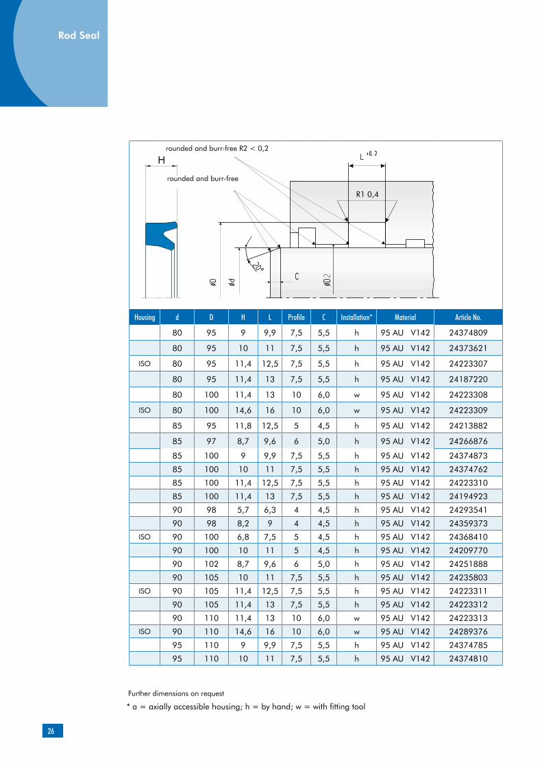
Housing d D H L Profile C Installation* Material Article No.
80 95 9 9,9 7,5 5,5 h 95 AU V142 24374809
80 95 10 11 7,5 5,5 h 95 AU V142 24373621
ISO 80 95 11,4 12,5 7,5 5,5 h 95 AU V142 24223307
80 95 11,4 13 7,5 5,5 h 95 AU V142 24187220
80 100 11,4 13 10 6,0 w 95 AU V142 24223308
ISO 80 100 14,6 16 10 6,0 w 95 AU V142 24223309
85 95 11,8 12,5 5 4,5 h 95 AU V142 24213882
85 97 8,7 9,6 6 5,0 h 95 AU V142 24266876
85 100 9 9,9 7,5 5,5 h 95 AU V142 24374873
85 100 10 11 7,5 5,5 h 95 AU V142 24374762
85 100 11,4 12,5 7,5 5,5 h 95 AU V142 24223310
85 100 11,4 13 7,5 5,5 h 95 AU V142 24194923
90 98 5,7 6,3 4 4,5 h 95 AU V142 24293541
90 98 8,2 9 4 4,5 h 95 AU V142 24359373
ISO 90 100 6,8 7,5 5 4,5 h 95 AU V142 24368410
90 100 10 11 5 4,5 h 95 AU V142 24209770
90 102 8,7 9,6 6 5,0 h 95 AU V142 24251888
90 105 10 11 7,5 5,5 h 95 AU V142 24235803
ISO 90 105 11,4 12,5 7,5 5,5 h 95 AU V142 24223311
90 105 11,4 13 7,5 5,5 h 95 AU V142 24223312
90 110 11,4 13 10 6,0 w 95 AU V142 24223313
ISO 90 110 14,6 16 10 6,0 w 95 AU V142 24289376
95 110 9 9,9 7,5 5,5 h 95 AU V142 24374785
95 110 10 11 7,5 5,5 h 95 AU V142 24374810
rounded and burr-free R2 < 0,2
rounded and burr-free

27
Further dimensions on request
* a = axially accessible housing; h = by hand; w = with fitting tool
Housing d D H L Profile C Installation* Material Article No.
95 110 11,8 13 7,5 5,5 h 95 AU V142 24369674
95 115 11,4 13 10 6,0 w 95 AU V142 24265228
95 115 12 13,2 10 6,0 w 95 AU V142 24374811
100 115 9 9,9 7,5 5,5 h 95 AU V142 24374763
100 115 10 11 7,5 5,5 h 95 AU V142 24235802
100 115 10,9 12 7,5 5,5 h 95 AU V142 24266877
100 115 11,4 13 7,5 5,5 h 95 AU V142 24223314
100 120 11,4 13 10 6,0 w 95 AU V142 24223316
100 120 12 13,2 10 6,0 w 95 AU V142 24374793
ISO 100 120 14,6 16 10 6,0 h 95 AU V142 24187222
105 115 10 11 5 4,5 h 95 AU V142 24366780
105 115 12 13 5 4,5 h 95 AU V142 24213883
105 120 11,4 12,5 7,5 5,5 h 95 AU V142 24300392
105 125 14,6 16 10 6,0 h 95 AU V142 24223317
110 120 7,7 8,5 5 4,5 h 95 AU V142 24369546
110 125 9 9,9 7,5 5,5 h 95 AU V142 24374786
ISO 110 125 9,6 10,6 7,5 5,5 h 95 AU V142 24368411
110 125 10,9 12 7,5 5,5 h 95 AU V142 24239427
110 125 12 13 7,5 5,5 h 95 AU V142 24242341
110 130 11,8 13 10 6,0 h 95 AU V142 24376016
ISO 110 130 14,6 16 10 6,0 w 95 AU V142 24223318
115 130 10,9 12 7,5 5,5 h 95 AU V142 24251889
115 135 14,6 16 10 6,0 w 95 AU V142 24223319
115 140 17,3 19 12,5 6,5 w 95 AU V142 24361949
120 135 10,9 12 7,5 5,5 h 95 AU V142 24360190
120 140 14,6 16 10 6,0 h 95 AU V142 24223320
120 145 17,3 19 12,5 6,5 w 95 AU V142 24371176
125 140 10,9 12 7,5 5,5 h 95 AU V142 24251890
ISO 125 145 14,6 16 10 6,0 h 95 AU V142 24223321
125 155 17,3 19 15 7,5 w 95 AU V142 24371643
130 140 15 16 5 4,5 h 95 AU V142 24213884
130 145 10 11 7,5 5,5 h 95 AU V142 24359621
130 145 13,7 15 7,5 5,5 h 95 AU V142 24362610
130 145 14,6 16 7,5 5,5 h 95 AU V142 24358619
130 150 14,6 16 10 6,0 h 95 AU V142 24223322
130 160 17,3 19 15 7,5 w 95 AU V142 24370486
135 155 14,6 16 10 6,0 a 95 AU V142 24360106
135 165 17,3 19 15 7,5 w 95 AU V142 24362625
28
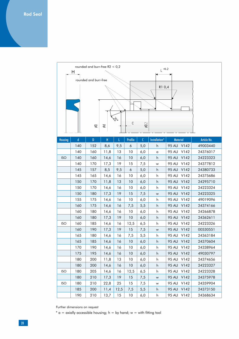
Housing d D H L Profile C Installation* Material Article No.
140 152 8,6 9,5 6 5,0 h 95 AU V142 49003440
140 160 11,8 13 10 6,0 a 95 AU V142 24376017
ISO 140 160 14,6 16 10 6,0 h 95 AU V142 24223323
140 170 17,3 19 15 7,5 w 95 AU V142 24377812
145 157 8,5 9,5 6 5,0 h 95 AU V142 24380733
145 165 14,6 16 10 6,0 h 95 AU V142 24375686
150 170 11,8 13 10 6,0 h 95 AU V142 24295710
150 170 14,6 16 10 6,0 h 95 AU V142 24223324
150 180 17,3 19 15 7,5 w 95 AU V142 24223325
155 175 14,6 16 10 6,0 h 95 AU V142 49019096
160 175 14,6 16 7,5 5,5 h 95 AU V142 24374166
160 180 14,6 16 10 6,0 h 95 AU V142 24266878
160 180 17,3 19 10 6,0 h 95 AU V142 24362611
ISO 160 185 14,6 16 12,5 6,5 h 95 AU V142 24223326
160 190 17,3 19 15 7,5 w 95 AU V142 00530551
165 180 14,6 16 7,5 5,5 h 95 AU V142 24363184
165 185 14,6 16 10 6,0 h 95 AU V142 24370604
170 190 14,6 16 10 6,0 h 95 AU V142 24338964
175 195 14,6 16 10 6,0 h 95 AU V142 49030797
180 200 11,8 13 10 6,0 h 95 AU V142 24374656
180 200 14,6 16 10 6,0 h 95 AU V142 24223327
ISO 180 205 14,6 16 12,5 6,5 h 95 AU V142 24223328
180 210 17,3 19 15 7,5 w 95 AU V142 24375978
ISO 180 210 22,8 25 15 7,5 w 95 AU V142 24359904
185 200 11,4 12,5 7,5 5,5 h 95 AU V142 24373150
190 210 13,7 15 10 6,0 h 95 AU V142 24368634
Rod Seal
Further dimensions on request
* a = axially accessible housing; h = by hand; w = with fitting tool
rounded and burr-free R2 < 0,2
rounded and burr-free
29
Further dimensions on request
* a = axially accessible housing; h = by hand; w = with fitting tool
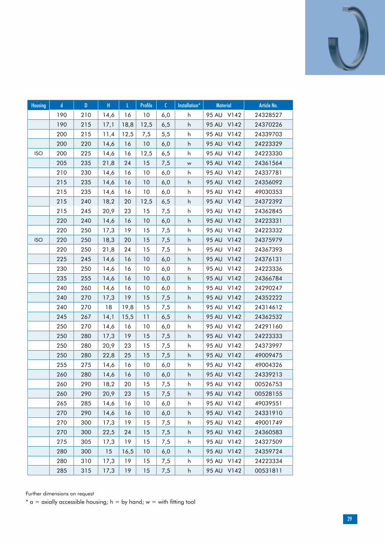
Housing d D H L Profile C Installation* Material Article No.
190 210 14,6 16 10 6,0 h 95 AU V142 24328527
190 215 17,1 18,8 12,5 6,5 h 95 AU V142 24370226
200 215 11,4 12,5 7,5 5,5 h 95 AU V142 24339703
200 220 14,6 16 10 6,0 h 95 AU V142 24223329
ISO 200 225 14,6 16 12,5 6,5 h 95 AU V142 24223330
205 235 21,8 24 15 7,5 w 95 AU V142 24361564
210 230 14,6 16 10 6,0 h 95 AU V142 24337781
215 235 14,6 16 10 6,0 h 95 AU V142 24356092
215 235 14,6 16 10 6,0 h 95 AU V142 49030353
215 240 18,2 20 12,5 6,5 h 95 AU V142 24372392
215 245 20,9 23 15 7,5 h 95 AU V142 24362845
220 240 14,6 16 10 6,0 h 95 AU V142 24223331
220 250 17,3 19 15 7,5 h 95 AU V142 24223332
ISO 220 250 18,3 20 15 7,5 h 95 AU V142 24375979
220 250 21,8 24 15 7,5 h 95 AU V142 24367393
225 245 14,6 16 10 6,0 h 95 AU V142 24376131
230 250 14,6 16 10 6,0 h 95 AU V142 24223336
235 255 14,6 16 10 6,0 h 95 AU V142 24366784
240 260 14,6 16 10 6,0 h 95 AU V142 24290247
240 270 17,3 19 15 7,5 h 95 AU V142 24352222
240 270 18 19,8 15 7,5 h 95 AU V142 24314612
245 267 14,1 15,5 11 6,5 h 95 AU V142 24362532
250 270 14,6 16 10 6,0 h 95 AU V142 24291160
250 280 17,3 19 15 7,5 h 95 AU V142 24223333
250 280 20,9 23 15 7,5 h 95 AU V142 24373997
250 280 22,8 25 15 7,5 h 95 AU V142 49009475
255 275 14,6 16 10 6,0 h 95 AU V142 49004326
260 280 14,6 16 10 6,0 h 95 AU V142 24339213
260 290 18,2 20 15 7,5 h 95 AU V142 00526753
260 290 20,9 23 15 7,5 h 95 AU V142 00528155
265 285 14,6 16 10 6,0 h 95 AU V142 49039551
270 290 14,6 16 10 6,0 h 95 AU V142 24331910
270 300 17,3 19 15 7,5 h 95 AU V142 49001749
270 300 22,5 24 15 7,5 h 95 AU V142 24360583
275 305 17,3 19 15 7,5 h 95 AU V142 24327509
280 300 15 16,5 10 6,0 h 95 AU V142 24359724
280 310 17,3 19 15 7,5 h 95 AU V142 24223334
285 315 17,3 19 15 7,5 h 95 AU V142 00531811

30
Rod Seal
Further dimensions on request
* a = axially accessible housing; h = by hand; w = with fitting tool
Housing d D H L Profile C Installation* Material Article No.
290 320 17,3 19 15 7,5 h 95 AU V142 24356384
300 330 17,3 19 15 7,5 h 95 AU V142 24351902
300 330 21,5 23,6 15 7,5 h 95 AU V142 24377304
300 330 21,8 24 15 7,5 h 95 AU V142 24361028
320 340 14,6 16 10 10 h 95 AU V142 24357237
320 350 22,8 25 15 11 h 95 AU V142 24359549
320 360 29,1 32 20 14 h 95 AU V142 24359550
330 360 22,8 25 15 11 h 95 AU V142 24359743
340 360 14,6 16 10 10 h 95 AU V142 24369208
340 370 22,8 26 15 11 h 95 AU V142 24360008
345 365 14,6 16 10 10 h 95 AU V142 49002919
350 370 14,6 16 10 10 h 95 AU V142 24357238
350 380 22,8 25 15 11 h 95 AU V142 24359746
360 380 14,6 16 10 10 h 95 AU V142 24359719
360 400 29,1 32 20 14 h 95 AU V142 49022458
370 400 22,8 25 15 11 h 95 AU V142 24359749
370 400 23,8 26 15 11 h 95 AU V142 49036122
380 400 14,6 16 10 10 h 95 AU V142 24359750
380 410 22,8 25 15 11 h 95 AU V142 49001346
380 420 29,1 32 20 14 h 95 AU V142 24359751
385 415 23,8 26 15 11 h 95 AU V142 00527751
390 420 22,8 25 15 11 h 95 AU V142 24359752
rounded and burr-free R2 < 0,2
rounded and burr-free
31
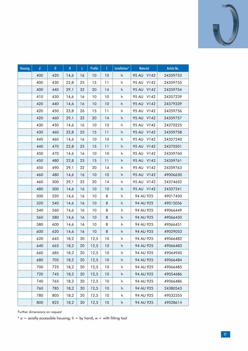
Further dimensions on request
* a = axially accessible housing; h = by hand; w = with fitting tool
Housing d D H L Profile C Installation* Material Article No.
400 420 14,6 16 10 10 h 95 AU V142 24359753
400 430 22,8 25 15 11 h 95 AU V142 24359755
400 440 29,1 32 20 14 h 95 AU V142 24359754
410 430 14,6 16 10 10 h 95 AU V142 24357239
420 440 14,6 16 10 10 h 95 AU V142 24379339
420 450 23,8 26 15 11 h 95 AU V142 24359756
420 460 29,1 32 20 14 h 95 AU V142 24359757
430 450 14,6 16 10 10 h 95 AU V142 24370225
430 460 22,8 25 15 11 h 95 AU V142 24359758
440 460 14,6 16 10 10 h 95 AU V142 24357240
440 470 22,8 25 15 11 h 95 AU V142 24370501
450 470 14,6 16 10 10 h 95 AU V142 24359760
450 480 22,8 25 15 11 h 95 AU V142 24359761
450 490 29,1 32 20 14 h 95 AU V142 24359763
460 480 14,6 16 10 10 h 95 AU V142 49006630
460 500 29,1 32 20 14 h 95 AU V142 24374652
480 500 14,6 16 10 10 h 95 AU V142 24357241
500 520 14,6 16 10 8 h 94 AU 925 49017450
520 540 14,6 16 10 8 h 94 AU 925 49015056
540 560 14,6 16 10 8 h 94 AU 925 49066449
560 580 14,6 16 10 8 h 94 AU 925 49066450
580 600 14,6 16 10 8 h 94 AU 925 49066451
600 620 14,6 16 10 8 h 94 AU 925 49029053
620 645 18,2 20 12,5 10 h 94 AU 925 49066482
640 665 18,2 20 12,5 10 h 94 AU 925 49066483
660 685 18,2 20 12,5 10 h 94 AU 925 49064940
680 705 18,2 20 12,5 10 h 94 AU 925 49066484
700 725 18,2 20 12,5 10 h 94 AU 925 49066485
720 745 18,2 20 12,5 10 h 94 AU 925 49054686
740 765 18,2 20 12,5 10 h 94 AU 925 49066486
760 785 18,2 20 12,5 10 h 94 AU 925 24380543
780 805 18,2 20 12,5 10 h 94 AU 925 49032355
800 825 18,2 20 12,5 10 h 94 AU 925 49028614

32
Rod Seal
Housing d D H L Profile C Installation* Material Article No.
820 845 18,2 20 12,5 10 h 94 AU 925 49066487
840 865 18,2 20 12,5 10 h 94 AU 925 49066488
860 885 18,2 20 12,5 10 h 94 AU 925 49066489
880 905 18,2 20 12,5 10 h 94 AU 925 49062164
900 925 18,2 20 12,5 10 h 94 AU 925 49066490
920 945 18,2 20 12,5 10 h 94 AU 925 24378523
940 965 18,2 20 12,5 10 h 94 AU 925 49022199
960 990 22,8 25 15 11 h 94 AU 925 49066491
980 1010 22,8 25 15 11 h 94 AU 925 49066492
1000 1030 22,8 25 15 11 h 94 AU 925 49066493
Further dimensions on request
* a = axially accessible housing; h = by hand; w = with fitting tool
rounded and burr-free R2 < 0,2
rounded and burr-free
33
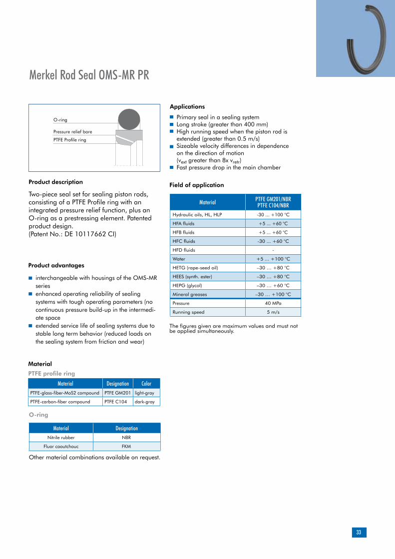
Product description
Product advantages
interchangeable with housings of the OMS-MR seriesenhanced operating reliability of sealing systems with tough operating parameters (no continuous pressure build-up in the intermedi-ate spaceextended service life of sealing systems due to stable long term behavior (reduced loads on the sealing system from friction and wear)
PTFE profile ring
Material Designation ColorPTFE-glass-fiber-MoS2 compound PTFE GM201 light-gray
PTFE-carbon-fiber compound PTFE C104 dark-gray
O-ring
Material DesignationNitrile rubber NBR
Fluor caoutchouc FKM
Applications
Two-piece seal set for sealing piston rods, consisting of a PTFE Profile ring with an integrated pressure relief function, plus an O-ring as a prestressing element. Patented product design.(Patent No.: DE 10117662 CI)
Merkel Rod Seal OMS-MR PR
Other material combinations available on request.
Material
Primary seal in a sealing systemLong stroke (greater than 400 mm)High running speed when the piston rod is extended (greater than 0.5 m/s)Sizeable velocity differences in dependence on the direction of motion (vext greater than 8x vretr) Fast pressure drop in the main chamber
Material PTFE GM201/NBR PTFE C104/NBR
Hydraulic oils, HL, HLP -30 ... +100 °C
HFA fluids +5 ... +60 °C
HFB fluids +5 ... +60 °C
HFC fluids -30 ... +60 °C
HFD fluids -
Water +5 ... +100 °C
HETG (rape-seed oil) –30 … +80 °C
HEES (synth. ester) –30 … +80 °C
HEPG (glycol) –30 … +60 °C
Mineral greases –30 … +100 °C
Pressure 40 MPa
Running speed 5 m/s
O-ring
Pressure relief bore
PTFE Profile ring
Field of application
The figures given are maximum values and must not be applied simultaneously.
34
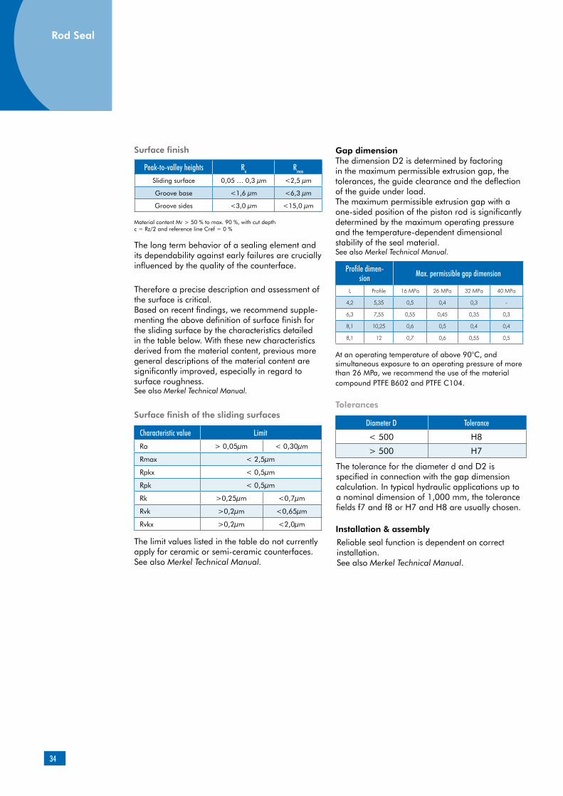
Surface finish
Material content Mr > 50 % to max. 90 %, with cut depth c = Rz/2 and reference line Cref = 0 %
The long term behavior of a sealing element and its dependability against early failures are crucially influenced by the quality of the counterface.
Therefore a precise description and assessment of the surface is critical.Based on recent findings, we recommend supple-menting the above definition of surface finish for the sliding surface by the characteristics detailed in the table below. With these new characteristics derived from the material content, previous more general descriptions of the material content are significantly improved, especially in regard to surface roughness. See also Merkel Technical Manual.
Surface finish of the sliding surfaces
Characteristic value Limit
Ra > 0,05µm < 0,30µm
Rmax < 2,5µm
Rpkx < 0,5µm
Rpk < 0,5µm
Rk >0,25µm <0,7µm
Rvk >0,2µm <0,65µm
Rvkx >0,2µm <2,0µm
The limit values listed in the table do not currently apply for ceramic or semi-ceramic counterfaces.See also Merkel Technical Manual.
Gap dimensionThe dimension D2 is determined by factoring in the maximum permissible extrusion gap, the tolerances, the guide clearance and the deflection of the guide under load. The maximum permissible extrusion gap with a one-sided position of the piston rod is significantly determined by the maximum operating pressure and the temperature-dependent dimensional stability of the seal material. See also Merkel Technical Manual.
Profile dimen-sion Max. permissible gap dimension
L Profile 16 MPa 26 MPa 32 MPa 40 MPa
4,2 5,35 0,5 0,4 0,3 -
6,3 7,55 0,55 0,45 0,35 0,3
8,1 10,25 0,6 0,5 0,4 0,4
8,1 12 0,7 0,6 0,55 0,5
At an operating temperature of above 90°C, and simultaneous exposure to an operating pressure of more than 26 MPa, we recommend the use of the material compound PTFE B602 and PTFE C104.
Tolerances
Diameter D Tolerance
< 500 H8
> 500 H7
The tolerance for the diameter d and D2 is specified in connection with the gap dimension calculation. In typical hydraulic applications up to a nominal dimension of 1,000 mm, the tolerance fields f7 and f8 or H7 and H8 are usually chosen.
Installation & assembly
Reliable seal function is dependent on correct installation.See also Merkel Technical Manual.
Rod Seal
Peak-to-valley heights Ra Rmax
Sliding surface 0,05 … 0,3 µm <2,5 µm
Groove base <1,6 µm <6,3 µm
Groove sides <3,0 µm <15,0 µm

35
Functional principle
Ill. 2
The Omegat OMS-MR PR features an integrated pressure relief function. As soon as the pressure in the intermediate space pz becomes greater than the main-compartment pressure pH (caused, for example, by unfavorable velocity conditions during extension and retraction), the seal can be relied on to relieve the pressure. The sealing function of the Omegat OMS-MR PR corresponds to that of the field-proven Omegat seals.
pZ = pressure in the intermediate space; pH = pressure in main compartment
Pressure relief in non-operative state
Intermediate space Intermediate space Main compartmentMain compartment
Pressure relief in function
36
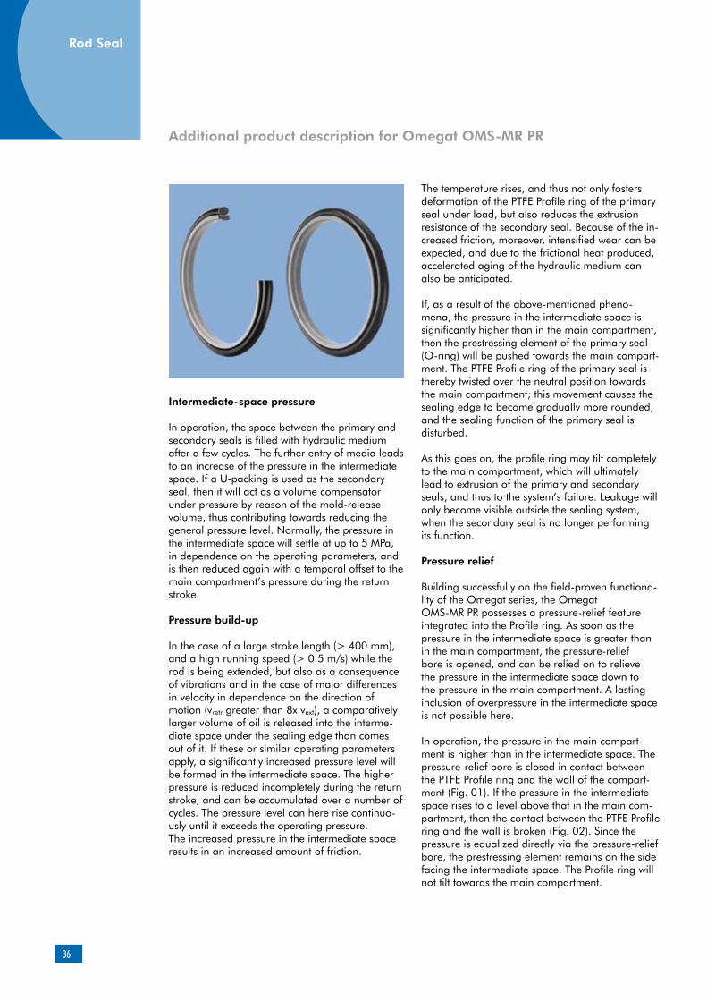
Intermediate-space pressure
In operation, the space between the primary and secondary seals is filled with hydraulic medium after a few cycles. The further entry of media leads to an increase of the pressure in the intermediate space. If a U-packing is used as the secondary seal, then it will act as a volume compensator under pressure by reason of the mold-release volume, thus contributing towards reducing the general pressure level. Normally, the pressure in the intermediate space will settle at up to 5 MPa, in dependence on the operating parameters, and is then reduced again with a temporal offset to the main compartment’s pressure during the return stroke.
Pressure build-up
In the case of a large stroke length (> 400 mm), and a high running speed (> 0.5 m/s) while the rod is being extended, but also as a consequence of vibrations and in the case of major differences in velocity in dependence on the direction of motion (vretr greater than 8x vext), a comparatively larger volume of oil is released into the interme-diate space under the sealing edge than comes out of it. If these or similar operating parameters apply, a significantly increased pressure level will be formed in the intermediate space. The higher pressure is reduced incompletely during the return stroke, and can be accumulated over a number of cycles. The pressure level can here rise continuo-usly until it exceeds the operating pressure.The increased pressure in the intermediate space results in an increased amount of friction.
The temperature rises, and thus not only fosters deformation of the PTFE Profile ring of the primary seal under load, but also reduces the extrusion resistance of the secondary seal. Because of the in-creased friction, moreover, intensified wear can be expected, and due to the frictional heat produced, accelerated aging of the hydraulic medium can also be anticipated.
If, as a result of the above-mentioned pheno-mena, the pressure in the intermediate space is significantly higher than in the main compartment, then the prestressing element of the primary seal (O-ring) will be pushed towards the main compart-ment. The PTFE Profile ring of the primary seal is thereby twisted over the neutral position towards the main compartment; this movement causes the sealing edge to become gradually more rounded, and the sealing function of the primary seal is disturbed.
As this goes on, the profile ring may tilt completely to the main compartment, which will ultimately lead to extrusion of the primary and secondary seals, and thus to the system’s failure. Leakage will only become visible outside the sealing system, when the secondary seal is no longer performing its function.
Pressure relief
Building successfully on the field-proven functiona-lity of the Omegat series, the Omegat OMS-MR PR possesses a pressure-relief feature integrated into the Profile ring. As soon as the pressure in the intermediate space is greater than in the main compartment, the pressure-relief bore is opened, and can be relied on to relieve the pressure in the intermediate space down to the pressure in the main compartment. A lasting inclusion of overpressure in the intermediate space is not possible here.
In operation, the pressure in the main compart-ment is higher than in the intermediate space. The pressure-relief bore is closed in contact between the PTFE Profile ring and the wall of the compart-ment (Fig. 01). If the pressure in the intermediate space rises to a level above that in the main com-partment, then the contact between the PTFE Profile ring and the wall is broken (Fig. 02). Since the pressure is equalized directly via the pressure-relief bore, the prestressing element remains on the side facing the intermediate space. The Profile ring will not tilt towards the main compartment.
Additional product description for Omegat OMS-MR PR
Rod Seal

37
Fig. 01 Fig. 02
With the patented pressure-relief feature, the pressure in the intermediate space is held inde-pendently of the operating conditions at a level favorable for continuous operation. By virtue of the low thermal and mechanical stress on the sealing elements, a stable long term behavior is achieved, and the sealing system’s service life is extended.
The functionality of the pressure-relief feature renders the sealing system tolerant to the ex-ternal influences acting on it during operation. Operating reliability is thus enhanced across the board by using the Omegat OMS-MR PR.
Using the Omegat OMS-MR PR makes an im-portant contribution towards the reliability and long lifetimes of hydraulic cylinders.
Using the Omegat OMS-MR PR will eliminate downtimes caused by intermediate-space pressure, thus substantially reducing your complaint-related costs and cutting the amount of maintenance required by up to 30 %.
pZ = pressure in the intermediate space; pH = pressure in main compartment
Pressure relief in non-operative state
Intermediate space Intermediate space Main compartmentMain compartment
Pressure relief in function

38
d D H L Profile C Material Article No.
50 65,1 5,9 6,3 7,55 5,5 PTFE C104/NBR 49029429
50 65,1 5,9 6,3 7,55 5,5 PTFE GM201/NBR 49004614
55 70,1 5,9 6,3 7,55 5,5 PTFE C104/NBR 49019333
55 70,1 5,9 6,3 7,55 5,5 PTFE GM201/NBR 49014635
60 75,1 5,9 6,3 7,55 5,5 PTFE GM201/NBR 49012253
65 80,1 5,9 6,3 7,55 5,5 PTFE C104/NBR 49021364
70 85,1 5,9 6,3 7,55 5,5 PTFE C104/NBR 49017738
70 85,1 5,9 6,3 7,55 5,5 PTFE GM201/NBR 49008472
75 90,1 5,9 6,3 7,55 5,5 PTFE C104/NBR 49018476
75 90,1 5,9 6,3 7,55 5,5 PTFE GM201/NBR 49022320
80 95,1 5,9 6,3 7,55 5,5 PTFE GM201/NBR 49016403
85 100,1 5,9 6,3 7,55 5,5 PTFE C104/NBR 49018477
85 100,1 5,9 6,3 7,55 5,5 PTFE GM201/NBR 49018521
90 105,1 5,9 6,3 7,55 5,5 PTFE C104/NBR 49017739
95 110,1 5,9 6,3 7,55 5,5 PTFE C104/NBR 49021365
95 110,1 5,9 6,3 7,55 5,5 PTFE GM201/NBR 49023416
100 115,1 5,9 6,3 7,55 5,5 PTFE C104/NBR 49021366
100 115,1 5,9 6,3 7,55 5,5 PTFE GM201/NBR 49020572
105 120,1 5,9 6,3 7,55 5,5 PTFE GM201/NBR 49003864
110 125,1 5,9 6,3 7,55 5,5 PTFE C104/NBR 49017740
110 125,1 5,9 6,3 7,55 5,5 PTFE GM201/NBR 49012225
115 130,1 5,9 6,3 7,55 5,5 PTFE GM201/NBR 49018445
120 135,1 5,9 6,3 7,55 5,5 PTFE C104/NBR 49017277
120 135,1 5,9 6,3 7,55 5,5 PTFE GM201/NBR 49012945
125 140,1 5,9 6,3 7,55 5,5 PTFE C104/NBR 49017741
125 140,1 5,9 6,3 7,55 5,5 PTFE GM201/NBR 49010807
Further dimensions on request
Rod Seal
rounded and burr-free R2 < 0,2
rounded and burr-free

39
Further dimensions on request
d D H L Profile C Material Article No.
130 145,1 5,9 6,3 7,55 5,5 PTFE C104/NBR 49036920
130 145,1 5,9 6,3 7,55 5,5 PTFE GM201/NBR 49012252
135 150,1 5,9 6,3 7,55 5,5 PTFE C104/NBR 49018331
140 155,1 5,9 6,3 7,55 5,5 PTFE C104/NBR 49024657
140 155,1 5,9 6,3 7,55 5,5 PTFE GM201/NBR 49004553
145 160,1 5,9 6,3 7,55 5,5 PTFE C104/NBR 49017742
150 165,1 5,9 6,3 7,55 5,5 PTFE C104/NBR 49020172
150 165,1 5,9 6,3 7,55 5,5 PTFE GM201/NBR 49005153
155 170,1 5,9 6,3 7,55 5,5 PTFE C104/NBR 49018944
160 175,1 5,9 6,3 7,55 5,5 PTFE C104/NBR 49017743
170 185,1 5,9 6,3 7,55 5,5 PTFE C104/NBR 49018943
170 185,1 5,9 6,3 7,55 5,5 PTFE GM201/NBR 49015207
180 195,1 5,9 6,3 7,55 5,5 PTFE C104/NBR 49017744
180 195,1 5,9 6,3 7,55 5,5 PTFE GM201/NBR 49023809
190 205,1 5,9 6,3 7,55 5,5 PTFE GM201/NBR 49023810
200 220,5 7,6 8,1 10,25 8 PTFE C104/NBR 49017745
200 220,5 7,6 8,1 10,25 8 PTFE GM201/NBR 49023811
210 230,5 7,6 8,1 10,25 8 PTFE C104/NBR 49015913
210 230,5 7,6 8,1 10,25 8 PTFE GM201/NBR 49023822
215 235,5 7,6 8,1 10,25 8 PTFE C104/NBR 49023880
220 240,5 7,6 8,1 10,25 8 PTFE C104/NBR 49017746
230 250,5 7,6 8,1 10,25 8 PTFE GM201/NBR 49004615
240 260,5 7,6 8,1 10,25 8 PTFE C104/NBR 49018772
250 270,5 7,6 8,1 10,25 8 PTFE C104/NBR 49017747
250 270,5 7,6 8,1 10,25 8 PTFE GM201/NBR 49009053
260 284 7,6 8,1 12 8 PTFE C104/NBR 49019084
265 289 7,6 8,1 12 8 PTFE C104/NBR 49017636
280 304 7,6 8,1 12 8 PTFE C104/NBR 49017748
295 319 7,6 8,1 12 8 PTFE C104/NBR 49017637
310 334 7,6 8,1 12 8 PTFE C104/NBR 49023881
320 344 7,6 8,1 12 8 PTFE C104/NBR 49024658
330 354 7,6 8,1 12 8 PTFE GM201/NBR 49004616
335 359 7,6 8,1 12 8 PTFE C104/NBR 49017638
340 364 7,6 8,1 12 8 PTFE C104/NBR 49021631
355 379 7,6 8,1 12 8 PTFE C104/NBR 49017750
360 384 7,6 8,1 12 8 PTFE C104/NBR 49024660
375 399 7,6 8,1 12 8 PTFE C104/NBR 49026725
380 404 7,6 8,1 12 8 PTFE C104/NBR 49017639

40
Further dimensions on request
d D H L Profile C Material Article No.
400 424 7,6 8,1 12 8 PTFE C104/NBR 49017751
470 494 7,6 8,1 12 8 PTFE C104/NBR 49017641
530 554 7,6 8,1 12 8 PTFE GM201/NBR 49033643
545 569 7,6 8,1 12 8 PTFE C104/NBR 49035524
590 614 7,6 8,1 12 8 PTFE C104/NBR 49020078
600 642 7,6 8,1 12 8 PTFE C104/NBR 49017643
630 654 7,6 8,1 12 8 PTFE C104/NBR 49023709
670 697,3 8,7 9,5 13,65 11 PTFE C104/NBR 49017644
730 757,3 8,7 9,5 13,65 11 PTFE C104/NBR 49018768
750 777,3 8,7 9,5 13,65 11 PTFE C104/NBR 49017645
Rod Seal
rounded and burr-free R2 < 0,2
rounded and burr-free

41
Merkel Omegat OMSU-MR PR
O-ring
Product description
Two-piece seal set for sealing piston rods, consi-sting of a Polyurethane Profile ring with an inte-grated pressure-relief function and an O-ring as the prestressing element.
Product advantages high operating reliability due to integrated pressure-relief feature
Material Designation ColorPolyurethane 95 AU V142 dark-blue
O-ring
Material DesignationNitrile rubber NBR
Field of application
Material 95 AU V142/NBRHydraulic oils, HL, HLP -30 ... +100 °C
HFA fluids +5 … +50 °C
HFB fluids +5 … +50 °C
HFC fluids –30 … +40 °C
HFD fluids -
Water +5 … +50 °C
HETG (rape-seed oil) –30 … +60 °C
HEES (synth. ester) –30 … +80 °C
HEPG (glycol) –30 … +50 °C
Mineral greases –30 … +100 °C
Pressure 16 MPa
Running speed 0,5 m/s
The figures given are maximum values and must not be applied simultaneously.
Surface finish
Peak-to-valley heights Ra Rmax
Sliding surface 0,05 … 0,3 µm <2,5 µm
Groove base <1,6 µm <6,3 µm
Groove sides <3,0 µm <15,0 µm
Material content Mr > 50 % to max. 90 %, with cut depth c = Rz/2 and reference line Cref = 0 %
The long term behavior of a sealing element and its dependability against early failures are cru-cially influenced by the quality of the counterface. Therefore a precise description and assessment of the surface is critical.
Based on recent findings, we recommend supple-menting the above definition of surface finish for the sliding surface by the characteristics detailed in the table below. With these new characteristics derived from the material content, previous more general descriptions of the material content are significantly improved, especially in regard to surface roughness.See also Merkel Technical Manual.
MaterialPolyurethane profile ring
Pressure-relief bore
Polyurethane profile ring
Application
can be used as an individual seal in conjunc-tion with a double wiperoperating pressure up to 16 MPa
42
Surface finish of the sliding surfaces
Characteristic value Limit
Ra > 0,05µm < 0,30µm
Rmax < 2,5µm
Rpkx < 0,5µm
Rpk < 0,5µm
Rk >0,25µm <0,7µm
Rvk >0,2µm <0,65µm
Rvkx >0,2µm <2,0µm
The limit values listed in the table do not currently apply for ceramic or semi-ceramic counterfaces.
Gap dimensionThe dimension D2 is determined by factoring in the maximum permissible extrusion gap, the tole-rances, the guide clearance, the deflection of the guide under load, and the pipe expansion. See also Merkel Technical Manual.
The maximum permissible extrusion gap with a one-sided position of the piston rod is significantly determined by the maximum operating pressure and the temperature-dependent dimensional stabi-lity of the seal material.
Profile dimension Max. permissible gap dimensionL Profile 8 MPa 16 MPa
6,3 7,55 0,5 0,2
8,1 10,25 0,55 0,25
8,1 12 0,6 0,3
9,5 13,65 0,6 0,35
Tolerances
Diameter Tolerance
D H8
The tolerance for the diameters d and D2 is specified in connection with the gap dimension calculati-on. In typical hydraulic applications up to a nominal dimension of 1,000 mm, the tolerance fields f7 and f8 or H7 and H8 are usually chosen.
Design notesPlease note our general design remarks in the Merkel Technical Manual.
Rod Seal
Installation & assembly
Reliable seal function is dependent on correct installation. See also Merkel Technical Manual
43
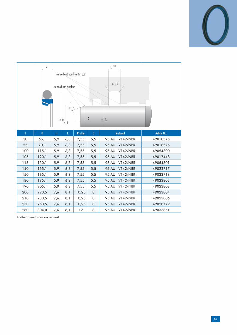
d D H L Profile C Material Article No.
50 65,1 5,9 6,3 7,55 5,5 95 AU V142/NBR 49018575
55 70,1 5,9 6,3 7,55 5,5 95 AU V142/NBR 49018576
100 115,1 5,9 6,3 7,55 5,5 95 AU V142/NBR 49054300
105 120,1 5,9 6,3 7,55 5,5 95 AU V142/NBR 49017448
115 130,1 5,9 6,3 7,55 5,5 95 AU V142/NBR 49054301
140 155,1 5,9 6,3 7,55 5,5 95 AU V142/NBR 49022717
150 165,1 5,9 6,3 7,55 5,5 95 AU V142/NBR 49022718
180 195,1 5,9 6,3 7,55 5,5 95 AU V142/NBR 49023802
190 205,1 5,9 6,3 7,55 5,5 95 AU V142/NBR 49023803
200 220,5 7,6 8,1 10,25 8 95 AU V142/NBR 49023804
210 230,5 7,6 8,1 10,25 8 95 AU V142/NBR 49023806
230 250,5 7,6 8,1 10,25 8 95 AU V142/NBR 49028779
280 304,0 7,6 8,1 12 8 95 AU V142/NBR 49033851
Further dimensions on request.
44
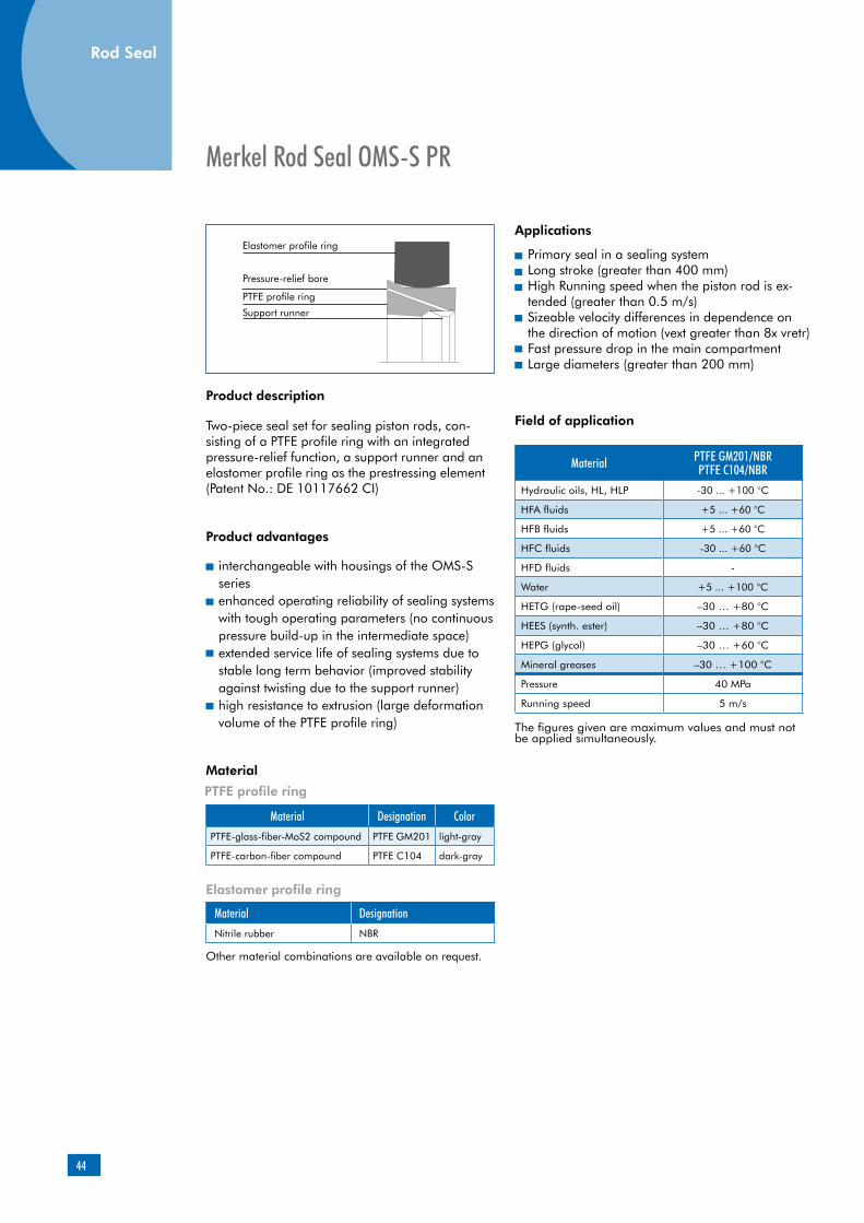
Product description
Product advantages
interchangeable with housings of the OMS-S seriesenhanced operating reliability of sealing systems with tough operating parameters (no continuous pressure build-up in the intermediate space)extended service life of sealing systems due to stable long term behavior (improved stability against twisting due to the support runner)high resistance to extrusion (large deformation volume of the PTFE profile ring)
PTFE profile ring
Elastomer profile ring
Material DesignationNitrile rubber NBR
Applications
Two-piece seal set for sealing piston rods, con-sisting of a PTFE profile ring with an integrated pressure-relief function, a support runner and an elastomer profile ring as the prestressing element (Patent No.: DE 10117662 CI)
Merkel Rod Seal OMS-S PR
Other material combinations are available on request.
Material
Primary seal in a sealing systemLong stroke (greater than 400 mm)High Running speed when the piston rod is ex-tended (greater than 0.5 m/s)Sizeable velocity differences in dependence on the direction of motion (vext greater than 8x vretr)Fast pressure drop in the main compartmentLarge diameters (greater than 200 mm)
Material PTFE GM201/NBR PTFE C104/NBR
Hydraulic oils, HL, HLP -30 ... +100 °C
HFA fluids +5 ... +60 °C
HFB fluids +5 ... +60 °C
HFC fluids -30 ... +60 °C
HFD fluids -
Water +5 ... +100 °C
HETG (rape-seed oil) –30 … +80 °C
HEES (synth. ester) –30 … +80 °C
HEPG (glycol) –30 … +60 °C
Mineral greases –30 … +100 °C
Pressure 40 MPa
Running speed 5 m/s
Elastomer profile ring
Pressure-relief bore
PTFE profile ring
Support runner
The figures given are maximum values and must not be applied simultaneously.
Rod Seal
Field of application
Material Designation ColorPTFE-glass-fiber-MoS2 compound PTFE GM201 light-gray
PTFE-carbon-fiber compound PTFE C104 dark-gray
45
Peak-to-valley heights Ra Rmax
Sliding surface 0,05 … 0,3 µm <2,5 µm
Groove base <1,6 µm <6,3 µm
Groove sides <3,0 µm <15,0 µm
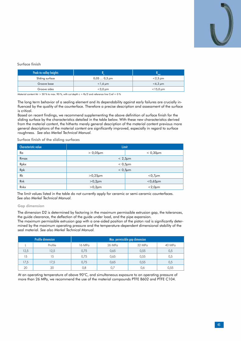
Surface finish
The long term behavior of a sealing element and its dependability against early failures are crucially in-fluenced by the quality of the counterface. Therefore a precise description and assessment of the surface is critical.Based on recent findings, we recommend supplementing the above definition of surface finish for the sliding surface by the characteristics detailed in the table below. With these new characteristics derived from the material content, the hitherto merely general description of the material content previous more general descriptions of the material content are significantly improved, especially in regard to surface roughness. See also Merkel Technical Manual.
Surface finish of the sliding surfaces
Characteristic value Limit
Ra > 0,05µm < 0,30µm
Rmax < 2,5µm
Rpkx < 0,5µm
Rpk < 0,5µm
Rk >0,25µm <0,7µm
Rvk >0,2µm <0,65µm
Rvkx >0,2µm <2,0µm
The limit values listed in the table do not currently apply for ceramic or semi-ceramic counterfaces. See also Merkel Technical Manual.
The dimension D2 is determined by factoring in the maximum permissible extrusion gap, the tolerances, the guide clearance, the deflection of the guide under load, and the pipe expansion.The maximum permissible extrusion gap with a one-sided position of the piston rod is significantly deter-mined by the maximum operating pressure and the temperature-dependent dimensional stability of the seal material. See also Merkel Technical Manual.
Profile dimension Max. permissible gap dimension
L Profile 16 MPa 26 MPa 32 MPa 40 MPa
12,5 12,5 0,75 0,65 0,55 0,5
15 15 0,75 0,65 0,55 0,5
17,5 17,5 0,75 0,65 0,55 0,5
20 20 0,8 0,7 0,6 0,55
At an operating temperature of above 90°C, and simultaneous exposure to an operating pressure of more than 26 MPa, we recommend the use of the material compounds PTFE B602 and PTFE C104.
Material content Mr > 50 % to max. 90 %, with cut depth c = Rz/2 and reference line Cref = 0 %
Gap dimension
46
Diameter Tolerance
D H7
The tolerance for the diameters d and D2 is specified in connection with the gap dimension calculation. In typical hydraulic applications up to a nominal dimension of 1,000 mm, the tolerance fields f7 and f8 or H7 and H8 are usually chosen.
Installation & assemblyReliable seal function is dependent on correct installation. See also Merkel Technical ManualSee also Merkel Technical Manual.
Intermediate space Main compartment
Design notesPlease note our general design remarks in the Merkel Technical Manual.
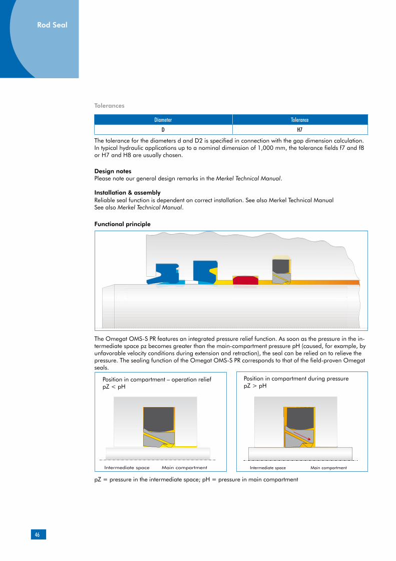
The Omegat OMS-S PR features an integrated pressure relief function. As soon as the pressure in the in-termediate space pz becomes greater than the main-compartment pressure pH (caused, for example, by unfavorable velocity conditions during extension and retraction), the seal can be relied on to relieve the pressure. The sealing function of the Omegat OMS-S PR corresponds to that of the field-proven Omegat seals.
Position in compartment – operation reliefpZ < pH
Position in compartment during pressure pZ > pH
Intermediate space Main compartment
pZ = pressure in the intermediate space; pH = pressure in main compartment
Functional principle
Rod Seal
Tolerances

47
d D H L Profile C R1 Material Article No.
320 350 14 15 15 12 0,8 PTFE GM201/NBR 49003542
340 370 14 15 15 12 0,8 PTFE GM201/NBR 530525
350 380 14 15 15 12 0,8 PTFE C104/NBR 49040590
360 390 14 15 15 12 0,8 PTFE GM201/NBR 49035736
380 410 14 15 15 12 0,8 PTFE GM201/NBR 49027663
400 430 14 15 15 12 0,8 PTFE GM201/NBR 49017441
410 440 14 15 15 12 0,8 PTFE GM201/NBR 49045104
420 450 14 15 15 12 0,8 PTFE GM201/NBR 49010869
450 480 14 15 15 12 0,8 PTFE GM201/NBR 49017442
490 520 14 15 15 12 0,8 PTFE GM201/NBR 49022435
500 530 14 15 15 12 0,8 PTFE GM201/NBR 49008121
530 565 16,4 17,5 17,5 12 1,2 PTFE GM201/NBR 49026032
540 575 16,4 17,5 17,5 12 1,2 PTFE GM201/NBR 49030424
570 605 16,4 17,5 17,5 12 1,2 PTFE GM201/NBR 49017443
570 605 16,4 17,5 17,5 12 1,2 PTFE C104/NBR 49024945
580 615 16,4 17,5 17,5 12 1,2 PTFE GM201/NBR 49015661
620 655 16,4 17,5 17,5 12 1,2 PTFE GM201/NBR 49014784
620 655 16,4 17,5 17,5 12 1,2 PTFE C104/NBR 49027857
640 675 16,4 17,5 17,5 12 1,2 PTFE C104/NBR 49046152
680 715 16,4 17,5 17,5 12 1,2 PTFE GM201/NBR 49026183
710 750 18,7 20 20 12 1,2 PTFE GM201/NBR 49017446
720 760 18,7 20 20 12 1,2 PTFE GM201/NBR 49004522
730 770 18,7 20 20 12 1,2 PTFE GM201/NBR 49015650
780 820 18,7 20 20 12 1,2 PTFE GM201/NBR 49032356
790 830 18,7 20 20 12 1,2 PTFE GM201/NBR 49015649
800 840 18,7 20 20 12 1,2 PTFE GM201/NBR 49015797
Further dimensions on request.
rounded and burr-free rounded andburr-free R1 < 0,2
48
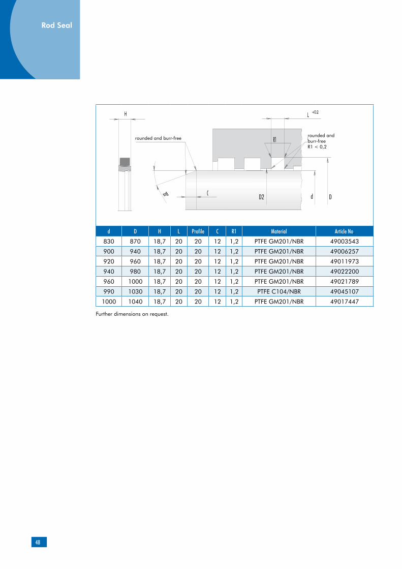
d D H L Profile C R1 Material Article No.
830 870 18,7 20 20 12 1,2 PTFE GM201/NBR 49003543
900 940 18,7 20 20 12 1,2 PTFE GM201/NBR 49006257
920 960 18,7 20 20 12 1,2 PTFE GM201/NBR 49011973
940 980 18,7 20 20 12 1,2 PTFE GM201/NBR 49022200
960 1000 18,7 20 20 12 1,2 PTFE GM201/NBR 49021789
990 1030 18,7 20 20 12 1,2 PTFE C104/NBR 49045107
1000 1040 18,7 20 20 12 1,2 PTFE GM201/NBR 49017447
Further dimensions on request.
Rod Seal
rounded and burr-free rounded andburr-free R1 < 0,2

49
Product description
Product advantages
can be used as an individual seal in a sealing system with a double wiper (short-stroke)stable long term behavior due to high stability against twisting (support runner)consistently high sealing effect due to optimized force flow to the sealing edge (elastomer profile ring)high resistance to extrusion (large deformation volume)shaft-friendly seal material
PTFE profile ring
Material Designation ColorPTFE-glass-fiber-MoS2 compound PTFE GM201 light-gray
PTFE-carbon-fiber compound PTFE C104 dark-gray
Elastomer profile ring
Material DesignationNitrile rubber NBR
Applications
Two-piece seal set for sealing piston rods, con-sisting of a PTFE profile ring, a support runner and an elastomer profile ring as the prestressing element.
Merkel Rod Seal OMS-S SR
Other material combinations available on request.
Material
Short stroke (up to 10 mm)Diameters from 310 mm
Material PTFE GM201/NBR PTFE C104/NBR
Hydraulic oils, HL, HLP -30 ... +100 °C
HFA fluids +5 ... +60 °C
HFB fluids +5 ... +60 °C
HFC fluids -30 ... +60 °C
HFD fluids -
Water +5 ... +100 °C
HETG (rape-seed oil) –30 … +80 °C
HEES (synth. ester) –30 … +80 °C
HEPG (glycol) –30 … +60 °C
Mineral greases –30 … +100 °C
Pressure 40 MPa
Running speed 5 m/s
Elatomer profile ring
PTFE profile ring
Support runner
The figures given are maximum values and must not be applied simultaneously.
Field of application
Peak-to-valley heights Ra Rmax
Sliding surface 0,05 … 0,3 µm <2,5 µm
Groove base <1,6 µm <6,3 µm
Groove sides <3,0 µm <15,0 µm
Surface finish
The long term behavior of a sealing element and its dependability against early failures are crucially influenced by the quality of the counterface. The-refore a precise description and assessment of the surface is critical.
Based on recent findings, we recommend supple-menting the above definition of surface finish for the sliding surface by the characteristics detailed in the table below. With these new characteri-stics derived from the material content, previous more general descriptions of the material content are significantly improved, especially in regard to surface roughness. See also Merkel Technical Manual.
Material content Mr > 50 % to max. 90 %, with cut depth c = Rz/2 and reference line Cref = 0 %
50
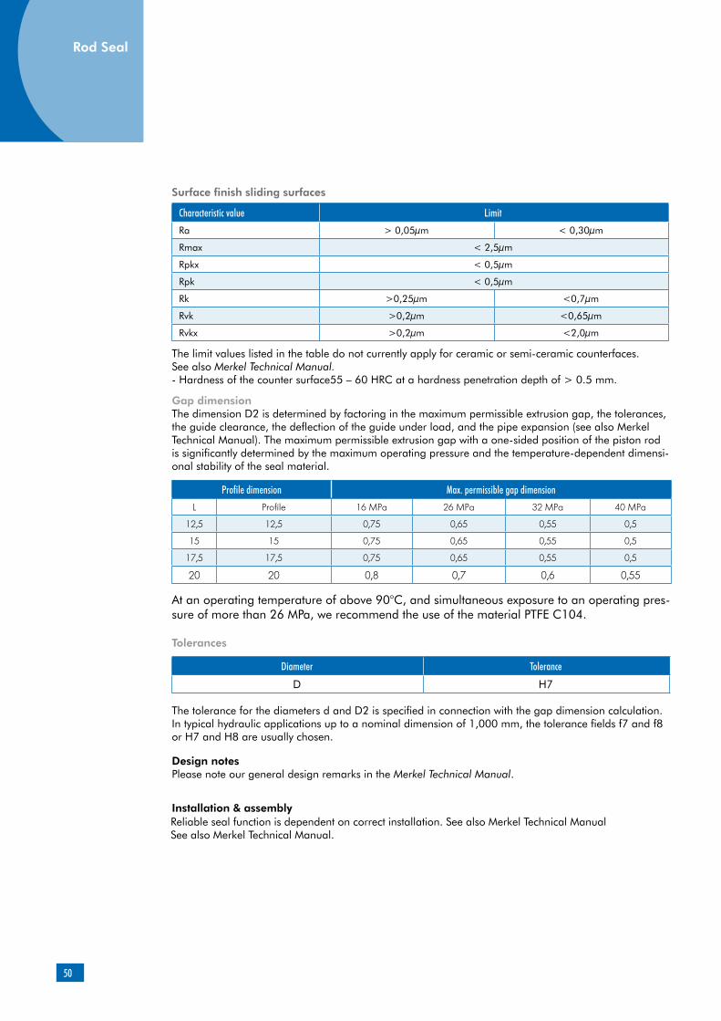
Surface finish sliding surfaces
Characteristic value Limit
Ra > 0,05µm < 0,30µm
Rmax < 2,5µm
Rpkx < 0,5µm
Rpk < 0,5µm
Rk >0,25µm <0,7µm
Rvk >0,2µm <0,65µm
Rvkx >0,2µm <2,0µm
The limit values listed in the table do not currently apply for ceramic or semi-ceramic counterfaces. See also Merkel Technical Manual.- Hardness of the counter surface55 – 60 HRC at a hardness penetration depth of > 0.5 mm.
Gap dimensionThe dimension D2 is determined by factoring in the maximum permissible extrusion gap, the tolerances, the guide clearance, the deflection of the guide under load, and the pipe expansion (see also Merkel Technical Manual). The maximum permissible extrusion gap with a one-sided position of the piston rod is significantly determined by the maximum operating pressure and the temperature-dependent dimensi-onal stability of the seal material.
Profile dimension Max. permissible gap dimension
L Profile 16 MPa 26 MPa 32 MPa 40 MPa
12,5 12,5 0,75 0,65 0,55 0,5
15 15 0,75 0,65 0,55 0,5
17,5 17,5 0,75 0,65 0,55 0,5
20 20 0,8 0,7 0,6 0,55
At an operating temperature of above 90°C, and simultaneous exposure to an operating pres-sure of more than 26 MPa, we recommend the use of the material PTFE C104.
Tolerances
Diameter Tolerance
D H7
The tolerance for the diameters d and D2 is specified in connection with the gap dimension calculation. In typical hydraulic applications up to a nominal dimension of 1,000 mm, the tolerance fields f7 and f8 or H7 and H8 are usually chosen.
Installation & assemblyReliable seal function is dependent on correct installation. See also Merkel Technical ManualSee also Merkel Technical Manual.
Design notesPlease note our general design remarks in the Merkel Technical Manual.
Rod Seal

51
d D H L Profile C Material Article No.
320 350 14 15 15 12 PTFE GM201/NBR 49010399
335 365 14 15 15 12 PTFE GM201/NBR 49008977
360 390 14 15 15 12 PTFE GM201/NBR 49009466
380 410 14 15 15 12 PTFE GM201/NBR 49019719
400 430 14 15 15 12 PTFE GM201/NBR 49012521
410 440 14 15 15 12 PTFE GM201/NBR 49019718
420 450 14 15 15 12 PTFE GM201/NBR 49008823
445 475 14 15 15 12 PTFE GM201/NBR 49004006
465 495 14 15 15 12 PTFE GM201/NBR 49009445
475 505 14 15 15 12 PTFE GM201/NBR 49012522
495 525 14 15 15 12 PTFE GM201/NBR 49010395
520 555 16,4 17,5 17,5 12 PTFE GM201/NBR 49008976
525 560 16,4 17,5 17,5 12 PTFE GM201/NBR 49012523
570 605 16,4 17,5 17,5 12 PTFE GM201/NBR 49009446
585 620 16,4 17,5 17,5 12 PTFE GM201/NBR 49012524
635 670 16,4 17,5 17,5 12 PTFE GM201/NBR 49012440
675 710 16,4 17,5 17,5 12 PTFE GM201/NBR 49012441
745 785 18,7 20 20 12 PTFE GM201/NBR 49012492
815 855 18,7 20 20 12 PTFE GM201/NBR 49012493
820 860 20 20 20 12 PTFE GM201/NBR 00528717
910 950 18,7 20 20 12 PTFE GM201/NBR 49012494
Further dimensions on request.
rounded and burr-free
rounded andburr-free R1 < 0,2
52
Merkel Omegat OMS-DR HB
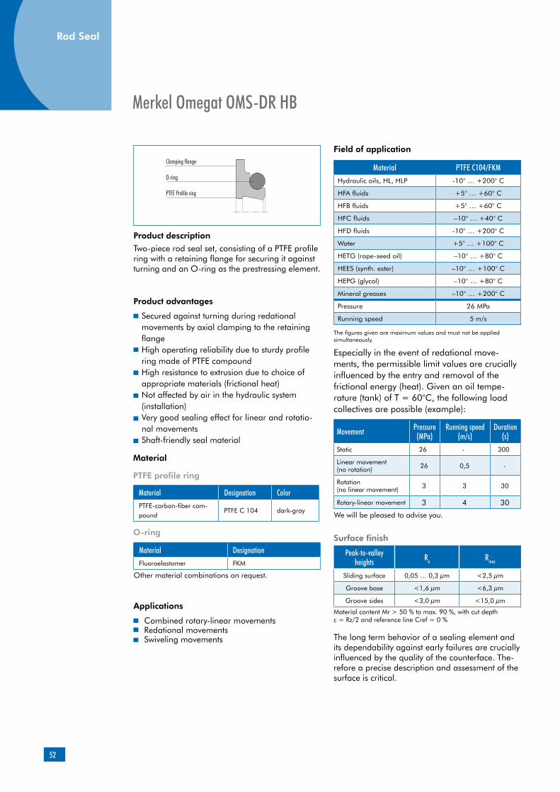
Product description
Product advantages
Secured against turning during redational movements by axial clamping to the retaining flangeHigh operating reliability due to sturdy profile ring made of PTFE compoundHigh resistance to extrusion due to choice of appropriate materials (frictional heat)Not affected by air in the hydraulic system (installation)Very good sealing effect for linear and rotatio-nal movements Shaft-friendly seal material
Material Designation ColorPTFE-carbon-fiber com-pound
PTFE C 104 dark-gray
O-ring
Material DesignationFluoroelastomer FKM
Clamping flange
O-ring
PTFE Profile ring
Applications
Two-piece rod seal set, consisting of a PTFE profile ring with a retaining flange for securing it against turning and an O-ring as the prestressing element.
Combined rotary-linear movementsRedational movementsSwiveling movements
Peak-to-valley heights Ra Rmax
Sliding surface 0,05 … 0,3 µm <2,5 µm
Groove base <1,6 µm <6,3 µm
Groove sides <3,0 µm <15,0 µm
Material content Mr > 50 % to max. 90 %, with cut depth c = Rz/2 and reference line Cref = 0 %
The long term behavior of a sealing element and its dependability against early failures are crucially influenced by the quality of the counterface. The-refore a precise description and assessment of the surface is critical.
Movement Pressure (MPa)
Running speed(m/s)
Duration(s)
Static 26 - 300
Linear movement (no rotation) 26 0,5 -
Rotation (no linear movement) 3 3 30
Rotary-linear movement 3 4 30
We will be pleased to advise you.
Surface finish
PTFE profile ring
Material
Other material combinations on request.
Field of application
Material PTFE C104/FKMHydraulic oils, HL, HLP -10° … +200° C
HFA fluids +5° … +60° C
HFB fluids +5° … +60° C
HFC fluids –10° … +40° C
HFD fluids -10° … +200° C
Water +5° … +100° C
HETG (rape-seed oil) –10° … +80° C
HEES (synth. ester) –10° … +100° C
HEPG (glycol) –10° … +80° C
Mineral greases –10° … +200° C
Pressure 26 MPa
Running speed 5 m/s
The figures given are maximum values and must not be applied simultaneously.
Especially in the event of redational move-ments, the permissible limit values are crucially influenced by the entry and removal of the frictional energy (heat). Given an oil tempe-rature (tank) of T = 60°C, the following load collectives are possible (example):
Rod Seal
53
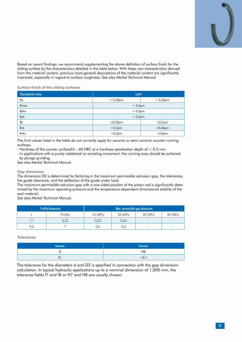
Based on recent findings, we recommend supplementing the above definition of surface finish for the sliding surface by the characteristics detailed in the table below. With these new characteristics derived from the material content, previous more general descriptions of the material content are significantly improved, especially in regard to surface roughness. See also Merkel Technical Manual.
Characteristic value Limit
Ra > 0,05µm < 0,30µm
Rmax < 2,5µm
Rpkx < 0,5µm
Rpk < 0,5µm
Rk >0,25µm <0,7µm
Rvk >0,2µm <0,65µm
Rvkx >0,2µm <2,0µm
Profile dimension Max. permissible gap dimension
L Profile 16 MPa 26 MPa 32 MPa 40 MPa
7,1 5,25 0,55 0,45 - -
9,5 7 0,6 0,5 - -
Gap dimensionThe dimension D2 is determined by factoring in the maximum permissible extrusion gap, the tolerances, the guide clearance, and the deflection of the guide under load. The maximum permissible extrusion gap with a one-sided position of the piston rod is significantly deter-mined by the maximum operating pressure and the temperature-dependent dimensional stability of the seal material. See also Merkel Technical Manual.
Tolerances
Diameter Tolerance
D H8
D1 +0,1
The tolerance for the diameters d and D2 is specified in connection with the gap dimension calculation. In typical hydraulic applications up to a nominal dimension of 1,000 mm, the tolerance fields f7 and f8 or H7 and H8 are usually chosen.
Surface finish of the sliding surfaces
The limit values listed in the table do not currently apply for ceramic or semi-ceramic counter-running surfaces. - Hardness of the counter surface55 – 60 HRC at a hardness penetration depth of > 0.5 mm.- In applications with a purely redational or swiveling movement, the running area should be achieved by plunge grindingSee also Merkel Technical Manual.

54
Rod Seal
Installation & assembly
Design notesFor installation, an axially accessible housing is required.The radial mobility in the vicinity of the seal should not be greater than +/- 0.1 mm.Radial movement at a high frequency may lead to impairment of the sealing effect.Please note our general design remarks in the Merkel Technical Manual.
For an optimum result, the installation sequence described below should be complied with. Fit O-ring on the PTFE profile ring. Insert seal set (profile ring with O-ring) into the housing, with the O-ring in front. Loosely pre-mount the cover plate. Install and align the piston rod. Tighten the cover plate with tightening screws evenly (crosswise).
Please note our general remarks on hydraulic seal assembly in the Merkel Technical Manual.

55
d D D1 H L L1 Profile C C1 Material Article No.
50 60,5 67,5 6 7,1 1,8 5,25 6 1,4 PTFE C104/FKM 49039487
55 65,5 72,5 6 7,1 1,8 5,25 6 1,4 PTFE C104/FKM 49029740
60 70,5 77,5 6 7,1 1,8 5,25 6 1,4 PTFE C104/FKM 49039488
65 75,5 82,5 6 7,1 1,8 5,25 6 1,4 PTFE C104/FKM 49039489
70 80,5 87,5 6 7,1 1,8 5,25 6 1,4 PTFE C104/FKM 49013105
80 90,5 97,5 6 7,1 1,8 5,25 6 1,4 PTFE C104/FKM 49018110
90 100,5 107,5 6 7,1 1,8 5,25 6 1,4 PTFE C104/FKM 49026577
100 110,5 117,5 6 7,1 1,8 5,25 6 1,4 PTFE C104/FKM 49034130
105 115,5 122,5 6 7,1 1,8 5,25 6 1,4 PTFE C104/FKM 49017975
120 130,5 137,5 6 7,1 1,8 5,25 6 1,4 PTFE C104/FKM 49020657
145 155,5 162,5 6 7,1 1,8 5,25 6 1,4 PTFE C104/FKM 49018107
170 184 192 8,6 9,5 2,8 7 8 1,6 PTFE C104/FKM 00530170
185 195,5 202,5 6 7,1 1,8 5,25 6 1,4 PTFE C104/FKM 49030376
190 200,5 207,5 6 7,1 1,8 5,25 6 1,4 PTFE C104/FKM 49018363
190 204 212 8,6 9,5 2,8 7 8 1,6 PTFE C104/FKM 00530171
220 234 242 8,6 9,5 2,8 7 8 1,6 PTFE C104/FKM 00530172
280 294 302 8,6 9,5 2,8 7 8 1,6 PTFE C104/FKM 00530173
315 329 337 8,6 9,5 2,8 7 8 1,6 PTFE C104/FKM 00530174
340 354 362 8,6 9,5 2,8 7 8 1,6 PTFE C104/FKM 00530175
380 394 402 8,6 9,5 2,8 7 8 1,6 PTFE C104/FKM 00530176
Further dimensions on request.
56

57
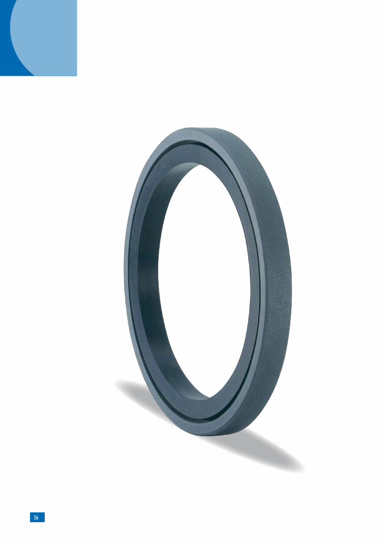
Merkel Omegat OMK-MR
O-ring
Product description
Two-piece seal set for sealing pistons, consisting of a PTFE profile ring and an O-ring as the prestres-sing element.
Product advantages
enhanced operating reliability with tough opera-ting parametersno „blow by“ with fast load changes, due to pressure activation groovesvery good pressure resistance capability and hardnessgood thermal conductivityhigh resistance to abrasionlow friction, stick-slip-free
Material Designation ColorPTFE-glass-fiber-MoS2 compound
PTFE GM201 light-gray
PTFE-carbon-fiber compound
PTFE C104 dark-gray
O-ring
Material Designation
Nitrile rubber NBR
MaterialPTFE profile ring
PTFE profile ring
Application
The OMK-MR is used with pistons stressed from both sides in:injection-molding machines, presses, agricultural machinery, truck loading cranes, control and regu-lating devices, rolling mills, handling equipment, marine hydraulics.
Material PTFE GM201/NBRPTFE C104/NBR
Hydraulic oils, HL, HLP -30 ... +100 °C
HFA fluids +5 … +60 °C
HFB fluids +5 … +60 °C
HFC fluids –30 … +60 °C
HFD fluids -
Water +5 … +100 °C
HETG (rape-seed oil) –30 … +80 °C
HEES (synth. ester) –30 … +80 °C
HEPG (glycol) –30 … +60 °C
Mineral greases –30 … +100 °C
Pressure 40 MPa
Running speed 5 m/s
Field of application
The figures given are maximum values and must not be applied simultaneously.
Material
Other material combinations are available on request.
Other material combinations are available on request.
Piston Seal
58
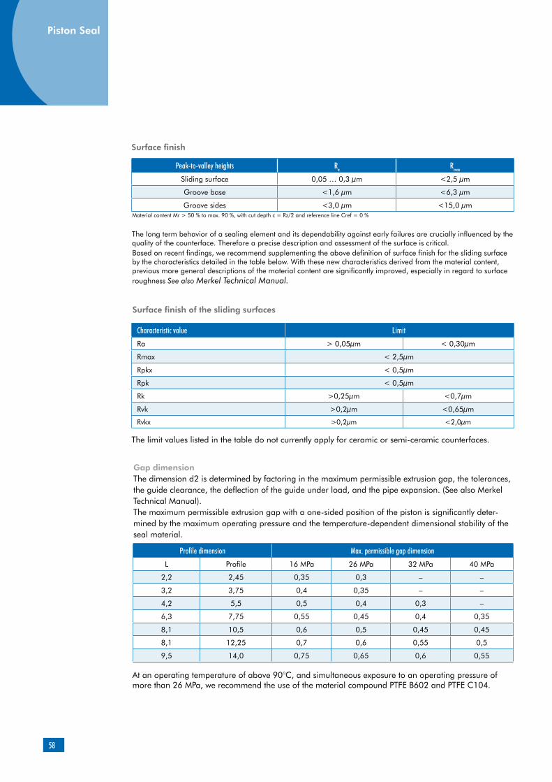
Piston Seal
Peak-to-valley heights Ra Rmax
Sliding surface 0,05 … 0,3 µm <2,5 µm
Groove base <1,6 µm <6,3 µm
Groove sides <3,0 µm <15,0 µmMaterial content Mr > 50 % to max. 90 %, with cut depth c = Rz/2 and reference line Cref = 0 %
Surface finish
The long term behavior of a sealing element and its dependability against early failures are crucially influenced by the quality of the counterface. Therefore a precise description and assessment of the surface is critical.Based on recent findings, we recommend supplementing the above definition of surface finish for the sliding surface by the characteristics detailed in the table below. With these new characteristics derived from the material content, previous more general descriptions of the material content are significantly improved, especially in regard to surface roughness See also Merkel Technical Manual.
Surface finish of the sliding surfaces
Characteristic value Limit
Ra > 0,05µm < 0,30µm
Rmax < 2,5µm
Rpkx < 0,5µm
Rpk < 0,5µm
Rk >0,25µm <0,7µm
Rvk >0,2µm <0,65µm
Rvkx >0,2µm <2,0µm
The limit values listed in the table do not currently apply for ceramic or semi-ceramic counterfaces.
Profile dimension Max. permissible gap dimension
L Profile 16 MPa 26 MPa 32 MPa 40 MPa
2,2 2,45 0,35 0,3 – –
3,2 3,75 0,4 0,35 – –
4,2 5,5 0,5 0,4 0,3 –
6,3 7,75 0,55 0,45 0,4 0,35
8,1 10,5 0,6 0,5 0,45 0,45
8,1 12,25 0,7 0,6 0,55 0,5
9,5 14,0 0,75 0,65 0,6 0,55
Gap dimensionThe dimension d2 is determined by factoring in the maximum permissible extrusion gap, the tolerances, the guide clearance, the deflection of the guide under load, and the pipe expansion. (See also Merkel Technical Manual).The maximum permissible extrusion gap with a one-sided position of the piston is significantly deter-mined by the maximum operating pressure and the temperature-dependent dimensional stability of the seal material.
At an operating temperature of above 90°C, and simultaneous exposure to an operating pressure of more than 26 MPa, we recommend the use of the material compound PTFE B602 and PTFE C104.
Piston Seal
59
Diameter d Tolerance
< 500 h8
> 500 h7
Tolerances
The tolerance for the diameters D and d2 is specified in connection with the gap dimension calculation. In typical hydraulic applications up to a nominal dimension of 1,000 mm, the tolerance fields f7 and f8 or H7 and H8 are usually chosen.
Design notesPlease note our general design remarks in the Merkel Technical Manual.
Installation & assemblyPlease note our general remarks on hydraulic seal assembly in the Merkel Technical Manual.

60
D d H L Profile C R1 Material Article No.
70 59 4 4,2 5,5 6,0 0,8 PTFE GM201 /NBR 24131860
70 59 4 4,2 5,5 6,0 0,8 PTFE C104/NBR 49021488
70 54,5 5,9 6,3 7,75 8,0 1,2 PTFE GM201/NBR 24131887
70 54,5 5,9 6,3 7,75 8,0 1,2 PTFE C104/NBR 49030513
75 64 4 4,2 5,5 6,0 0,8 PTFE GM201/NBR 24145486
75 59,5 5,9 6,3 7,75 8,0 1,2 PTFE GM201/NBR 24213523
80 64,5 5,9 6,3 7,75 8,0 1,2 PTFE GM201/NBR 24101263
80 64,5 5,9 6,3 7,75 8,0 1,2 PTFE C104/NBR 49018495
80 59 7,7 8,1 10,5 10,5 2,0 PTFE GM201/NBR 24131888
85 69,5 5,9 6,3 7,75 8,0 1,2 PTFE GM201/NBR 24223623
85 69,5 5,9 6,3 7,75 8,0 1,2 PTFE C104/NBR 49054674
85 64 7,7 8,1 10,5 10,5 2,0 PTFE GM201/NBR 24213524
90 74,5 5,9 6,3 7,75 8,0 1,2 PTFE GM201/NBR 24131861
90 74,5 5,9 6,3 7,75 8,0 1,2 PTFE C104/NBR 49018496
90 69 7,7 8,1 10,5 10,5 2,0 PTFE GM201/NBR 24131889
95 79,5 5,9 6,3 7,75 8,0 1,2 PTFE GM201/NBR 24199482
95 79,5 5,9 6,3 7,75 8,0 1,2 PTFE C104/NBR 49000291
95 74 7,7 8,1 10,5 10,5 2,0 PTFE GM201/NBR 24075603
100 89 4 4,2 5,5 6,0 0,8 PTFE GM201/NBR 24328829
100 84,5 5,9 6,3 7,75 8,0 1,2 PTFE GM201/NBR 24107904
100 84,5 5,9 6,3 7,75 8,0 1,2 PTFE C104/NBR 49002075
100 79 7,7 8,1 10,5 10,5 2,0 PTFE GM201/NBR 24077512
105 89,5 5,9 6,3 7,75 8,0 1,2 PTFE GM201/NBR 24187281
105 89,5 5,9 6,3 7,75 8,0 1,2 PTFE C104/NBR 49018497
110 94,5 5,9 6,3 7,75 8,0 1,2 PTFE GM201/NBR 24131862
110 94,5 5,9 6,3 7,75 8,0 1,2 PTFE C104/NBR 49020706
Further dimensions on request.
Piston Seal

61
Further dimensions on request.
D d H L Profile C R1 Material Article No.
110 89 7,7 8,1 10,5 10,5 2,0 PTFE GM201/NBR 24077514
112 91 7,7 8,1 10,5 10,5 2,0 PTFE C104/NBR 49054805
115 99,5 5,9 6,3 7,75 8,0 1,2 PTFE GM201/NBR 24131863
115 94 7,7 8,1 10,5 10,5 2,0 PTFE GM201/NBR 24131890
120 104,5 5,9 6,3 7,75 8,0 1,2 PTFE GM201/NBR 24186464
120 104,5 5,9 6,3 7,75 8,0 1,2 PTFE C104/NBR 49018498
120 99 7,7 8,1 10,5 10,5 2,0 PTFE GM201/NBR 24199999
122 106,5 5,9 6,3 7,75 8,0 1,2 PTFE C104/NBR 49055074
125 109,5 5,9 6,3 7,75 8,0 1,2 PTFE GM201/NBR 24109478
125 109,5 5,9 6,3 7,75 8,0 1,2 PTFE C104/NBR 49000292
125 104 7,7 8,1 10,5 10,5 2,0 PTFE GM201/NBR 24093346
130 114,5 5,9 6,3 7,75 8,0 1,2 PTFE GM201/NBR 24145852
130 114,5 5,9 6,3 7,75 8,0 1,2 PTFE C104/NBR 49041763
130 109 7,7 8,1 10,5 10,5 2,0 PTFE GM201/NBR 24077517
140 119 7,7 8,1 10,5 10,5 2,0 PTFE GM201/NBR 24075607
140 119 7,7 8,1 10,5 10,5 2,0 PTFE C104/NBR 49000293
149 128 7,7 8,1 10,5 10,5 2,0 PTFE C104/NBR 49000294
150 129 7,7 8,1 10,5 10,5 2,0 PTFE GM201/NBR 24075609
150 129 7,7 8,1 10,5 10,5 2,0 PTFE C104/NBR 49018499
160 139 7,7 8,1 10,5 10,5 2,0 PTFE GM201/NBR 24075673
160 139 7,7 8,1 10,5 10,5 2,0 PTFE C104/NBR 49018500
170 149 7,7 8,1 10,5 10,5 2,0 PTFE GM201/NBR 24131864
175 154 7,7 8,1 10,5 10,5 2,0 PTFE C104/NBR 49012838
180 159 7,7 8,1 10,5 10,5 2,0 PTFE GM201/NBR 24131865
180 159 7,7 8,1 10,5 10,5 2,0 PTFE C104/NBR 49000295
190 169 7,7 8,1 10,5 10,5 2,0 PTFE GM201/NBR 24131866
200 179 7,7 8,1 10,5 10,5 2,0 PTFE GM201 /NBR 24131867
210 189 7,7 8,1 10,5 10,5 2,0 PTFE GM201/NBR 24138658
210 189 7,7 8,1 10,5 10,5 2,0 PTFE C104/NBR 49036993
215 194 7,7 8,1 10,5 10,5 2,0 PTFE C104/NBR 49000267
220 199 7,7 8,1 10,5 10,5 2,0 PTFE GM201/NBR 24131868
220 199 7,7 8,1 10,5 10,5 2,0 PTFE C104/NBR 49045372
224 204 7,7 8,1 10,5 10,5 2,0 PTFE C104/NBR 49037026
230 209 7,7 8,1 10,5 10,5 2,0 PTFE GM201/NBR 24145853
230 209 7,7 8,1 10,5 10,5 2,0 PTFE C104/NBR 49000268
240 219 7,7 8,1 10,5 10,5 2,0 PTFE GM201/NBR 24107902
250 229 7,7 8,1 10,5 10,5 2,0 PTFE GM201/NBR 24131869
250 229 7,7 8,1 10,5 10,5 2,0 PTFE C104/NBR 49000269

62
Further dimensions on request.
D d H L Profile C R1 Material Article No.
255 234 7,7 8,1 10,5 10,5 2,0 PTFE C104/NBR 49030541
260 239 7,7 8,1 10,5 10,5 2,0 PTFE GM201/NBR 24223625
268 247 7,7 8,1 10,5 10,5 2,0 PTFE C104/NBR 49000270
270 249 7,7 8,1 10,5 10,5 2,0 PTFE GM201/NBR 24121481
280 259 7,7 8,1 10,5 10,5 2,0 PTFE GM201/NBR 24120265
280 259 7,7 8,1 10,5 10,5 2,0 PTFE C104/NBR 49035216
290 269 7,7 8,1 10,5 10,5 2,0 PTFE GM201/NBR 24275640
300 279 7,7 8,1 10,5 10,5 2,0 PTFE GM201/NBR 24179922
300 279 7,7 8,1 10,5 10,5 2,0 PTFE C104/NBR 49009207
310 289 7,7 8,1 10,5 10,5 2,0 PTFE GM201/NBR 24248946
310 289 7,7 8,1 10,5 10,5 2,0 PTFE C104/NBR 00533523
320 299 7,7 8,1 10,5 10,5 2,0 PTFE GM201/NBR 24131870
330 305,5 7,7 8,1 12,25 10,5 2,0 PTFE GM201/NBR 24105259
340 315,5 7,7 8,1 12,25 10,5 2,0 PTFE GM201/NBR 24213529
350 325,5 7,7 8,1 12,25 10,5 2,0 PTFE GM201/NBR 24199746
350 352,5 7,7 8,1 12,25 10,5 2,0 PTFE C104/NBR 49023944
360 335,5 7,7 8,1 12,25 10,5 2,0 PTFE GM201/NBR 24118300
370 345,5 7,7 8,1 12,25 10,5 2,0 PTFE GM201/NBR 24275649
380 356 7,7 8,1 12 10,5 2,0 PTFE GM201/NBR 24194142
385 360,5 7,7 8,1 12,25 10,5 2,0 PTFE C104/NBR 49026723
390 365,5 7,7 8,1 12,25 10,5 2,0 PTFE GM201/NBR 24145902
395 370,5 7,7 8,1 12,25 10,5 2,0 PTFE C104/NBR 49023945
400 375,5 7,7 8,1 12,25 10,5 2,0 PTFE GM201/NBR 24123281
410 385,5 7,7 8,1 12,25 10,5 2,0 PTFE GM201/NBR 24145195
420 395,5 7,7 8,1 12,25 10,5 2,0 PTFE GM201/NBR 24240756
430 405,5 7,7 8,1 12,25 10,5 2,0 PTFE GM201/NBR 24275683
Piston Seal
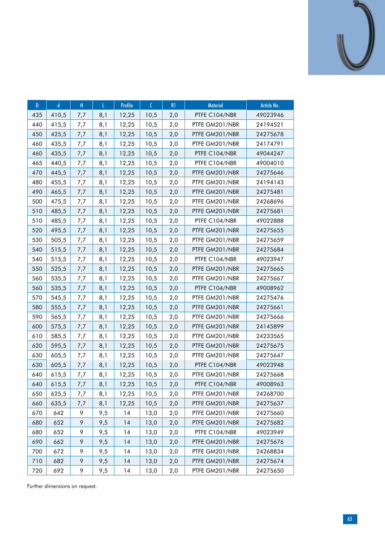
63
Further dimensions on request.
D d H L Profile C R1 Material Article No.
435 410,5 7,7 8,1 12,25 10,5 2,0 PTFE C104/NBR 49023946
440 415,5 7,7 8,1 12,25 10,5 2,0 PTFE GM201/NBR 24194521
450 425,5 7,7 8,1 12,25 10,5 2,0 PTFE GM201/NBR 24275678
460 435,5 7,7 8,1 12,25 10,5 2,0 PTFE GM201/NBR 24174791
460 435,5 7,7 8,1 12,25 10,5 2,0 PTFE C104/NBR 49044247
465 440,5 7,7 8,1 12,25 10,5 2,0 PTFE C104/NBR 49004010
470 445,5 7,7 8,1 12,25 10,5 2,0 PTFE GM201/NBR 24275646
480 455,5 7,7 8,1 12,25 10,5 2,0 PTFE GM201/NBR 24194143
490 465,5 7,7 8,1 12,25 10,5 2,0 PTFE GM201/NBR 24275481
500 475,5 7,7 8,1 12,25 10,5 2,0 PTFE GM201/NBR 24268696
510 485,5 7,7 8,1 12,25 10,5 2,0 PTFE GM201/NBR 24275681
510 485,5 7,7 8,1 12,25 10,5 2,0 PTFE C104/NBR 49022888
520 495,5 7,7 8,1 12,25 10,5 2,0 PTFE GM201/NBR 24275655
530 505,5 7,7 8,1 12,25 10,5 2,0 PTFE GM201/NBR 24275659
540 515,5 7,7 8,1 12,25 10,5 2,0 PTFE GM201/NBR 24275684
540 515,5 7,7 8,1 12,25 10,5 2,0 PTFE C104/NBR 49023947
550 525,5 7,7 8,1 12,25 10,5 2,0 PTFE GM201/NBR 24275665
560 535,5 7,7 8,1 12,25 10,5 2,0 PTFE GM201/NBR 24275667
560 535,5 7,7 8,1 12,25 10,5 2,0 PTFE C104/NBR 49008962
570 545,5 7,7 8,1 12,25 10,5 2,0 PTFE GM201/NBR 24275476
580 555,5 7,7 8,1 12,25 10,5 2,0 PTFE GM201/NBR 24275661
590 565,5 7,7 8,1 12,25 10,5 2,0 PTFE GM201/NBR 24275666
600 575,5 7,7 8,1 12,25 10,5 2,0 PTFE GM201/NBR 24145899
610 585,5 7,7 8,1 12,25 10,5 2,0 PTFE GM201/NBR 24233565
620 595,5 7,7 8,1 12,25 10,5 2,0 PTFE GM201/NBR 24275675
630 605,5 7,7 8,1 12,25 10,5 2,0 PTFE GM201/NBR 24275647
630 605,5 7,7 8,1 12,25 10,5 2,0 PTFE C104/NBR 49023948
640 615,5 7,7 8,1 12,25 10,5 2,0 PTFE GM201/NBR 24275668
640 615,5 7,7 8,1 12,25 10,5 2,0 PTFE C104/NBR 49008963
650 625,5 7,7 8,1 12,25 10,5 2,0 PTFE GM201/NBR 24268700
660 635,5 7,7 8,1 12,25 10,5 2,0 PTFE GM201/NBR 24275637
670 642 9 9,5 14 13,0 2,0 PTFE GM201/NBR 24275660
680 652 9 9,5 14 13,0 2,0 PTFE GM201/NBR 24275682
680 652 9 9,5 14 13,0 2,0 PTFE C104/NBR 49023949
690 662 9 9,5 14 13,0 2,0 PTFE GM201/NBR 24275676
700 672 9 9,5 14 13,0 2,0 PTFE GM201/NBR 24268834
710 682 9 9,5 14 13,0 2,0 PTFE GM201/NBR 24275674
720 692 9 9,5 14 13,0 2,0 PTFE GM201/NBR 24275650
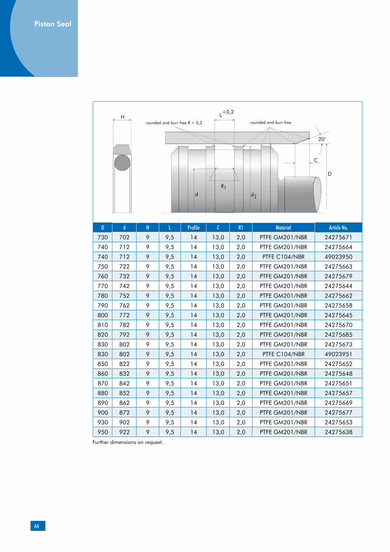
64
Further dimensions on request.
D d H L Profile C R1 Material Article No.
730 702 9 9,5 14 13,0 2,0 PTFE GM201/NBR 24275671
740 712 9 9,5 14 13,0 2,0 PTFE GM201/NBR 24275664
740 712 9 9,5 14 13,0 2,0 PTFE C104/NBR 49023950
750 722 9 9,5 14 13,0 2,0 PTFE GM201/NBR 24275663
760 732 9 9,5 14 13,0 2,0 PTFE GM201/NBR 24275679
770 742 9 9,5 14 13,0 2,0 PTFE GM201/NBR 24275644
780 752 9 9,5 14 13,0 2,0 PTFE GM201/NBR 24275662
790 762 9 9,5 14 13,0 2,0 PTFE GM201/NBR 24275658
800 772 9 9,5 14 13,0 2,0 PTFE GM201/NBR 24275645
810 782 9 9,5 14 13,0 2,0 PTFE GM201/NBR 24275670
820 792 9 9,5 14 13,0 2,0 PTFE GM201/NBR 24275685
830 802 9 9,5 14 13,0 2,0 PTFE GM201/NBR 24275673
830 802 9 9,5 14 13,0 2,0 PTFE C104/NBR 49023951
850 822 9 9,5 14 13,0 2,0 PTFE GM201/NBR 24275652
860 832 9 9,5 14 13,0 2,0 PTFE GM201/NBR 24275648
870 842 9 9,5 14 13,0 2,0 PTFE GM201/NBR 24275651
880 852 9 9,5 14 13,0 2,0 PTFE GM201/NBR 24275657
890 862 9 9,5 14 13,0 2,0 PTFE GM201/NBR 24275669
900 872 9 9,5 14 13,0 2,0 PTFE GM201/NBR 24275677
930 902 9 9,5 14 13,0 2,0 PTFE GM201/NBR 24275653
950 922 9 9,5 14 13,0 2,0 PTFE GM201/NBR 24275638
Piston Seal

65
Merkel Omegat OMK-DR HB
O-ring
Product description
Three-piece piston seal set, consisting of a PTFE profile ring, an O-ring as the prestressing element, and a PTFE sliding ring in the groove base.
Product advantagessecured against turning during redational mo-vements by profiled contact face to the O-ringoptimized friction contact condition during redational movement due to PTFE sliding ring in the groove base high sealing effect and favorable frictional behavior due to pressure relief of the grooved running surfacefast, reliable activation at pressure changes due to pressure activation grooveshigh operating reliability due to sturdy profile ring made of PTFE compoundshaft-friendly seal material
Material Designation ColorPTFE-glass-fiber-MoS2 compound
PTFE GM201 light-gray
O-ring
Material DesignationFluoroelastomer FKM
Field of application
Material PTFE GM201/FKMHydraulic oils, HL, HLP -10 ... +200 °C
HFA fluids +5 … +60 °C
HFB fluids +5 … +60 °C
HFC fluids –10 … +40 °C
HFD fluids -10 ... +200 °C
Water +5 … +100 °C
HETG (rape-seed oil) –10 … +80 °C
HEES (synth. ester) –10 … +100 °C
HEPG (glycol) –10 … +80 °C
Mineral greases –10 … +200 °C
Pressure 26 MPa
Running speed 5 m/s
The figures given are maximum values and must not be applied simultaneously.
Surface finish
Peak-to-valley heights Ra Rmax
Sliding surface 0,05 … 0,3 µm <2,5 µm
Groove base <1,6 µm <6,3 µm
Groove sides <3,0 µm <15,0 µm
Material
PTFE profile ring
PTFE sliding ring
PTFE profile ring
Application
Combined rotary-linear movementsRotational movementsSwiveling movements
PTFE sliding ring
Material Designation ColorPTFE PTFE V039 blue
Especially in the event of redational move-ments, the permissible limit values are crucially influenced by the entry and removal of the frictional energy (heat). Given an oil tempe-rature (tank) of T = 60°C, the following load collectives are possible (example):
Movement Pressure (MPa)
Running speed(m/s)
Duration(s)
Static 26 - 300
Stroke movement(no rotation) 26 0,5 -
Rotation(no linear movement) 3 3 30
Material content Mr > 50 % to max. 90 %, with cut depth c = Rz/2 and reference line Cref = 0 %
We will be pleased to advise you.
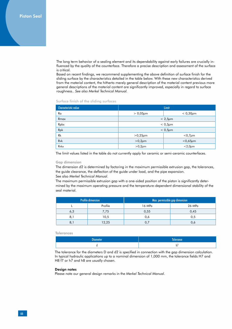
66
Surface finish of the sliding surfaces
Characteristic value Limit
Ra > 0,05µm < 0,30µm
Rmax < 2,5µm
Rpkx < 0,5µm
Rpk < 0,5µm
Rk >0,25µm <0,7µm
Rvk >0,2µm <0,65µm
Rvkx >0,2µm <2,0µm
The limit values listed in the table do not currently apply for ceramic or semi-ceramic counterfaces.
Gap dimensionThe dimension d2 is determined by factoring in the maximum permissible extrusion gap, the tolerances, the guide clearance, the deflection of the guide under load, and the pipe expansion.See also Merkel Technical Manual.The maximum permissible extrusion gap with a one-sided position of the piston is significantly deter-mined by the maximum operating pressure and the temperature-dependent dimensional stability of the seal material.
Profile dimension Max. permissible gap dimension
L Profile 16 MPa 26 MPa
6,3 7,75 0,55 0,45
8,1 10,5 0,6 0,5
8,1 12,25 0,7 0,6
Tolerances
Diameter Tolerance
d h7
The tolerance for the diameters D and d2 is specified in connection with the gap dimension calculation. In typical hydraulic applications up to a nominal dimension of 1,000 mm, the tolerance fields H7 and H8 f7 or h7 and h8 are usually chosen.
Design notesPlease note our general design remarks in the Merkel Technical Manual.
The long term behavior of a sealing element and its dependability against early failures are crucially in-fluenced by the quality of the counterface. Therefore a precise description and assessment of the surface is critical.Based on recent findings, we recommend supplementing the above definition of surface finish for the sliding surface by the characteristics detailed in the table below. With these new characteristics derived from the material content, the hitherto merely general description of the material content previous more general descriptions of the material content are significantly improved, especially in regard to surface roughness.. See also Merkel Technical Manual.
Piston Seal

67
Installation & assembly
For an optimum result, the installation sequence described below should be complied with: Stretch the PTFE sliding ring and fit it in the groove. The sliding ring is manufactured to be significantly smaller than the nominal diameter. The recovery of the PTFE sliding ring lasts only a brief moment. Additional calibration is not required. Stretch the O-ring and place it in the groove without twisting it. Use a fitting tool or (in the event of larger diameters) two special installation strips (Order No. 24346745) to stretch the PTFE profile ring evenly over the diameter and engage it in the groove. Local overstretching must, at all costs, be avoided here. Calibrate the PTFE profile ring (making sure that the lead-in chamfer is sufficiently large). The PTFE profile ring can (e.g. in water) be heated up to approx. 80°C in order to facilitate installation.
Please note our general remarks on hydraulic seal assembly in the Merkel Technical Manual, “Installing
Hydraulic Seals”.
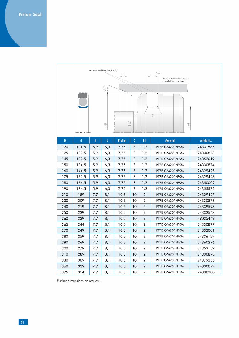
68
D d H L Profile C R1 Material Article No.
120 104,5 5,9 6,3 7,75 8 1,2 PTFE GM201/FKM 24331585
125 109,5 5,9 6,3 7,75 8 1,2 PTFE GM201/FKM 24330873
145 129,5 5,9 6,3 7,75 8 1,2 PTFE GM201/FKM 24352019
150 134,5 5,9 6,3 7,75 8 1,2 PTFE GM201/FKM 24330874
160 144,5 5,9 6,3 7,75 8 1,2 PTFE GM201/FKM 24329425
175 159,5 5,9 6,3 7,75 8 1,2 PTFE GM201/FKM 24329426
180 164,5 5,9 6,3 7,75 8 1,2 PTFE GM201/FKM 24350009
190 174,5 5,9 6,3 7,75 8 1,2 PTFE GM201/FKM 24355572
210 189 7,7 8,1 10,5 10 2 PTFE GM201/FKM 24329427
230 209 7,7 8,1 10,5 10 2 PTFE GM201/FKM 24330876
240 219 7,7 8,1 10,5 10 2 PTFE GM201/FKM 24339593
250 229 7,7 8,1 10,5 10 2 PTFE GM201/FKM 24332543
260 239 7,7 8,1 10,5 10 2 PTFE GM201/FKM 49035449
265 244 7,7 8,1 10,5 10 2 PTFE GM201/FKM 24330877
270 249 7,7 8,1 10,5 10 2 PTFE GM201/FKM 24332001
280 259 7,7 8,1 10,5 10 2 PTFE GM201/FKM 24336129
290 269 7,7 8,1 10,5 10 2 PTFE GM201/FKM 24360276
300 279 7,7 8,1 10,5 10 2 PTFE GM201/FKM 24353159
310 289 7,7 8,1 10,5 10 2 PTFE GM201/FKM 24330878
330 309 7,7 8,1 10,5 10 2 PTFE GM201/FKM 24379255
360 339 7,7 8,1 10,5 10 2 PTFE GM201/FKM 24330879
375 354 7,7 8,1 10,5 10 2 PTFE GM201/FKM 24330308
Further dimensions on request.
Piston Seal

69

70

71
Product description
Product advantages
enhanced functional reliability of the sealing system, due to additional sealing edge high operating reliability, due to sturdy profile ring made of PTFE compound (can briefly with-stand the full operating pressure)very good wiping capability for dirt adhering, due to dimensionally stable wiping edgeexcellent control and positioning characteristics due to favorable frictional behavior (stick-slip-free)
PTFE profile ring
Material Designation Color
PTFE-glass-fiber-MoS2 compound
PTFE GM201 light-gray
O-ringMaterial Designation
Nitrile rubber NBR
Fluoroelastomer FKM
Applications
Double wiper, consisting of a PTFE profile ring with one sealing and one wiping edge, plus two O-rings as prestressing elements.
Merkel Double Wiper PT 1
Material
Double wiper for improving overall sealing capabilities. The PT 1 is preferably used in con-junction with our rod seals OMS-MR PR, T 20 or LF 300.
Material PTFE GM201/NBR
Hydraulic oils, HL, HLP -30 ... +100 °C
HFA fluids +5 ... +60 °C
HFB fluids +5 ... +60 °C
HFC fluids -30 ... +60 °C
HFD fluids -
Water +5 ... +100 °C
HETG (rape-seed oil) –30 … +80 °C
HEES (synth. ester) –30 … +80 °C
HEPG (glycol) –30 … +60 °C
Mineral greases –30 … +100 °C
Running speed 5 m/s
O-ring
PTFE profile ring
Field of application
The figures given are maximum values and must not be applied simultaneously.
Material
Other material combinations are available on request.
Wiper
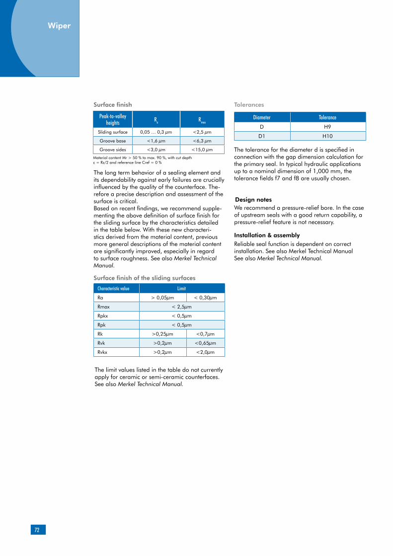
72
The long term behavior of a sealing element and its dependability against early failures are crucially influenced by the quality of the counterface. The-refore a precise description and assessment of the surface is critical.Based on recent findings, we recommend supple-menting the above definition of surface finish for the sliding surface by the characteristics detailed in the table below. With these new characteri-stics derived from the material content, previous more general descriptions of the material content are significantly improved, especially in regard to surface roughness. See also Merkel Technical Manual.
Surface finish of the sliding surfaces
Characteristic value Limit
Ra > 0,05µm < 0,30µm
Rmax < 2,5µm
Rpkx < 0,5µm
Rpk < 0,5µm
Rk >0,25µm <0,7µm
Rvk >0,2µm <0,65µm
Rvkx >0,2µm <2,0µm
The limit values listed in the table do not currently apply for ceramic or semi-ceramic counterfaces. See also Merkel Technical Manual.
Tolerances
Diameter Tolerance
D H9
D1 H10
The tolerance for the diameter d is specified in connection with the gap dimension calculation for the primary seal. In typical hydraulic applications up to a nominal dimension of 1,000 mm, the tolerance fields f7 and f8 are usually chosen.
Installation & assemblyReliable seal function is dependent on correct installation. See also Merkel Technical ManualSee also Merkel Technical Manual.
Peak-to-valley heights Ra Rmax
Sliding surface 0,05 … 0,3 µm <2,5 µm
Groove base <1,6 µm <6,3 µm
Groove sides <3,0 µm <15,0 µm
Surface finish
Material content Mr > 50 % to max. 90 %, with cut depth c = Rz/2 and reference line Cref = 0 %
We recommend a pressure-relief bore. In the case of upstream seals with a good return capability, a pressure-relief feature is not necessary.
Design notes
Wiper

73
d D D1 H L L1 Profile C R1 Material Article No.
40 48,8 41,5 6 6,3 10.3 4,4 3 1,2 PTFE GM201/NBR 49023486
45 53,8 46,5 6 6,3 10.3 4,4 3 1,2 PTFE GM201/NBR 49016648
50 58,8 51,5 6 6,3 10.3 4,4 3 1,2 PTFE GM201/NBR 49004617
55 63,8 56,5 6 6,3 10.3 4,4 3 1,2 PTFE GM201/NBR 49014632
60 68,8 61,5 6 6,3 10.3 4,4 3 1,2 PTFE GM201/NBR 00531996
65 73,8 66,5 6 6,3 10.3 4,4 3 1,2 PTFE GM201/NBR 24380154
70 82,2 72,0 7,7 8,1 12.1 6,1 4 2 PTFE GM201/NBR 24371776
75 87,2 77,0 7,7 8,1 12.1 6,1 4 2 PTFE GM201/NBR 49018473
80 92,2 82,0 7,7 8,1 12.1 6,1 4 2 PTFE GM201/NBR 49016404
85 97,2 87,0 7,7 8,1 12.1 6,1 4 2 PTFE GM201/NBR 24380155
95 107,2 97,0 7,7 8,1 12.1 6,1 4 2 PTFE GM201/NBR 24379210
100 112,2 102,0 7,7 8,1 12.1 6,1 4 2 PTFE GM201/NBR 24380032
105 117,2 107,0 7,7 8,1 12.1 6,1 4 2 PTFE GM201/NBR 24380095
110 122,2 112,0 7,7 8,1 12.1 6,1 4 2 PTFE GM201/NBR 24380092
120 132,2 122,0 7,7 8,1 12.1 6,1 4 2 PTFE GM201/NBR 49012837
125 137,2 127,0 7,7 8,1 12.1 6,1 6 2 PTFE GM201/NBR 24380156
130 142,2 132,0 7,7 8,1 12.1 6,1 6 2 PTFE GM201/NBR 49023823
140 156 142,0 11 11,5 15.5 8 6 2 PTFE GM201/NBR 49004558
145 161 147,0 11 11,5 15.5 8 6 2 PTFE GM201/NBR 24380702
150 166 152,0 11 11,5 15.5 8 6 2 PTFE GM201/NBR 49005139
155 171 157,0 11 11,5 15.5 8 6 2 PTFE GM201/NBR 24380703
160 176 162,0 11 11,5 15.5 8 6 2 PTFE GM201/NBR 49015836
170 186 172,0 11 11,5 15.5 8 6 2 PTFE GM201/NBR 24380704
175 191 177,0 11 11,5 15.5 8 6 2 PTFE GM201/NBR 24362382
180 196 182,0 11 11,5 15.5 8 6 2 PTFE GM201/NBR 00531957
200 216 202,0 11 11,5 15.5 8 6 2 PTFE GM201/NBR 24342233
Further dimensions on request.

74
d D D1 H L L1 Profile C R1 Material Article No.
210 226 212,0 11 11,5 15.5 8 8 2 PTFE GM201/NBR 24380705
220 236 222,0 11 11,5 15.5 8 8 2 PTFE GM201/NBR 49002400
230 246 232,0 11 11,5 15.5 8 8 2 PTFE GM201/NBR 49004618
240 256 242,0 11 11,5 15.5 8 8 2 PTFE GM201/NBR 00533355
250 266 252,0 11 11,5 15.5 8 8 2 PTFE GM201/NBR 49009052
280 296 282,0 11 11,5 15.5 8 8 2 PTFE GM201/NBR 49004005
310 326 312,0 11 11,5 15.5 8 8 2 PTFE GM201/NBR 49009461
320 336 322,0 11 11,5 15.5 8 8 2 PTFE GM201/NBR 49010398
330 346 332,0 11 11,5 15.5 8 8 2 PTFE GM201/NBR 49004619
335 351 337,0 11 11,5 15.5 8 8 2 PTFE GM201/NBR 49008975
360 376 362,0 11 11,5 15.5 8 8 2 PTFE GM201/NBR 49009462
380 396 382,0 11 11,5 15.5 8 8 2 PTFE GM201/NBR 49019716
400 424 402,5 14,8 15,5 15.6 12 8 2 PTFE GM201/NBR 49012517
410 434 412,5 14,8 15,5 15.7 12 8 2 PTFE GM201/NBR 49019717
420 444 422,5 14,8 15,5 15.8 12 8 2 PTFE GM201/NBR 49008822
510 534 512,5 14,8 15,5 15.9 12 8 2 PTFE GM201/NBR 49006826
520 544 522,5 14,8 15,5 15.10 12 8 2 PTFE GM201/NBR 49008973
570 594 572,5 14,8 15,5 15.11 12 8 2 PTFE GM201/NBR 49009444
620 644 622,5 14,8 15,5 15.12 12 8 2 PTFE GM201/NBR 49027854
640 664 642,5 14,8 15,5 15.13 12 8 2 PTFE GM201/NBR 00532207
Further dimensions on request.
Wiper

75
Product description
Product advantages
enhanced functional reliability of the sealing system due to additional sealing edge high operating reliability, due to sturdy profile ring made of PTFE compound (can briefly with-stand the maximum operating pressure)very good wiping capability for dirt adhering, due to dimensionally stable wiping edgesecured against turning during redational move-ments by profiled contact surface to the O-ringstick-slip-free operation, due to choice of appro-priate material (coefficient of friction)shaft-friendly seal material
Material
PTFE profile ring
Material Designation ColorPTFE-glass-fiber-MoS2-compound
PTFE GM201 light-gray
O-ring
Material DesignationFluoroelastomer FKM
Field of application
Material PTFE GM201/FKMHydraulic oils, HL, HLP -10 … +200 °C
HFA fluids +5 … +60 °C
HFB fluids +5 … +60 °C
HFC fluids –10 … +40 °C
HFD fluids -10 … +200 °C
Water +5 … +100 °C
HETG (rape-seed oil) –10 … +80 °C
HEES (synth. ester) –10 … +100 °C
HEPG (glycol) –10 … +80 °C
Mineral greases –10 … +200 °C
Running speed 5 m/s
The figures given are maximum values and must not be applied simultaneously.
Especially in the event of redational move-ments, the permissible limit values are crucially influenced by the entry and removal of the frictional energy (heat). Given an oil tempe-rature (tank) of T = 60°C, the following load collectives are possible (example):
Applications
Double wiper, consisting of a PTFE profile ring with one sealing and one wiping edge, plus two O-rings as prestressing elements.
Combined redary-stroke movementsRedational movementsSwiveling movements
Peak-to-valley heights Ra Rmax
Sliding surface 0,05 … 0,3 µm <2,5 µm
Groove base <1,6 µm <6,3 µm
Groove sides <3,0 µm <15,0 µm
Material content Mr > 50 % to max. 90 %, with cut depth c = Rz/2 and reference line Cref = 0 %
Movement Pressure (MPa)
Running speed(m/s)
Duration(s)
Linear movement (no rotation) - 5 -
Rotation(no linear movement) - 3 30
Rotary-linear movement - 4 30
We will be pleased to advise you.
Surface finish
The long term behavior of a sealing element and its dependability against early failures are crucially influenced by the quality of the counterface. The-refore a precise description and assessment of the surface is critical.
Merkel Double Wiper PT 1 DR-HB
O-ring
PTFE profile ring
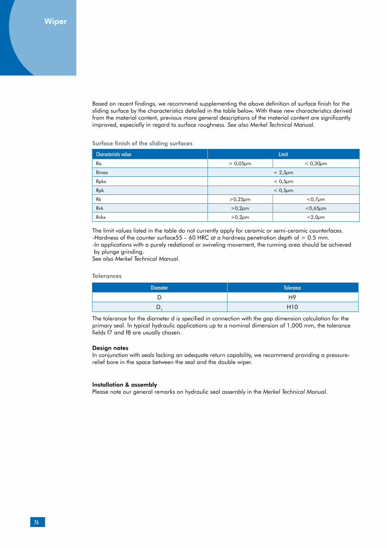
76
Based on recent findings, we recommend supplementing the above definition of surface finish for the sliding surface by the characteristics detailed in the table below. With these new characteristics derived from the material content, previous more general descriptions of the material content are significantly improved, especially in regard to surface roughness. See also Merkel Technical Manual.
Characteristic value Limit
Ra > 0,05µm < 0,30µm
Rmax < 2,5µm
Rpkx < 0,5µm
Rpk < 0,5µm
Rk >0,25µm <0,7µm
Rvk >0,2µm <0,65µm
Rvkx >0,2µm <2,0µm
Tolerances
Diameter Tolerance
D H9
D1 H10
Design notesIn conjunction with seals lacking an adequate return capability, we recommend providing a pressure-relief bore in the space between the seal and the double wiper.
Installation & assemblyPlease note our general remarks on hydraulic seal assembly in the Merkel Technical Manual.
Surface finish of the sliding surfaces
The limit values listed in the table do not currently apply for ceramic or semi-ceramic counterfaces.-Hardness of the counter surface55 – 60 HRC at a hardness penetration depth of > 0.5 mm.-In applications with a purely redational or swiveling movement, the running area should be achieved by plunge grinding.See also Merkel Technical Manual.
The tolerance for the diameter d is specified in connection with the gap dimension calculation for the primary seal. In typical hydraulic applications up to a nominal dimension of 1,000 mm, the tolerance fields f7 and f8 are usually chosen.
Wiper
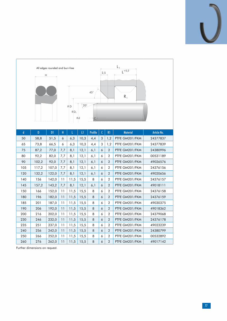
77
d D D1 H L L1 Profile C R1 Material Article No.
50 58,8 51,5 6 6,3 10,3 4,4 3 1,2 PTFE GM201/FKM 24377837
65 73,8 66,5 6 6,3 10,3 4,4 3 1,2 PTFE GM201/FKM 24377839
75 87,2 77,0 7,7 8,1 12,1 6,1 6 2 PTFE GM201/FKM 24380996
80 92,2 82,0 7,7 8,1 12,1 6,1 6 2 PTFE GM201/FKM 00531189
90 102,2 92,0 7,7 8,1 12,1 6,1 6 2 PTFE GM201/FKM 49026576
105 117,2 107,0 7,7 8,1 12,1 6,1 6 2 PTFE GM201/FKM 24376156
120 132,2 122,0 7,7 8,1 12,1 6,1 6 2 PTFE GM201/FKM 49020656
140 156 142,0 11 11,5 15,5 8 6 2 PTFE GM201/FKM 24376157
145 157,2 143,2 7,7 8,1 12,1 6,1 6 2 PTFE GM201/FKM 49018111
150 166 152,0 11 11,5 15,5 8 6 2 PTFE GM201/FKM 24376158
180 196 182,0 11 11,5 15,5 8 6 2 PTFE GM201/FKM 24376159
185 201 187,0 11 11,5 15,5 8 6 2 PTFE GM201/FKM 49030375
190 206 192,0 11 11,5 15,5 8 6 2 PTFE GM201/FKM 49018362
200 216 202,0 11 11,5 15,5 8 6 2 PTFE GM201/FKM 24379068
230 246 232,0 11 11,5 15,5 8 6 2 PTFE GM201/FKM 24376178
235 251 237,0 11 11,5 15,5 8 6 2 PTFE GM201/FKM 49023239
240 256 242,0 11 11,5 15,5 8 6 2 PTFE GM201/FKM 24380799
250 266 252,0 11 11,5 15,5 8 6 2 PTFE GM201/FKM 00532892
260 276 262,0 11 11,5 15,5 8 6 2 PTFE GM201/FKM 49017142
C
D
D
d
2,5
20°
45°
LL
1+0,2
R1
1
H
Ø
Ø
Ø
All edges rounded and burr-free
Further dimensions on request.

78

79
can replace current housings of type SB and SFhigh radial load capacityvery good guide-length utilization based on uniform stress distributionenhanced penetration of lubricating media based on optimized stress distribution within the contact zone between the guide bush and the counter surface (favorable frictional behavior)reduced propensity for stick-slip excellent sliding behavior over a short guiding distance (no jamming)
Product description
Product advantages
Profiled rod-type guide bush made of resin bon-ded fabric. Patented product design (patent No.: PCT/EP95/03874)
Applications
Long-stroke cylinder (piston-rod deflection)Short guiding distance (piston-rod tilting)Short stroke (inappropriate lubrication)Frictionally optimized sealing systemsReplacement for metallic guides
Merkel Guivex SBK Guide Bush
Material Designation Color
Resin bonded fabric HGW HG650 red
Resin bonded fabric HGW HG517 dark-gray
Material
Field of application
Guivex guide bushes can be used in all hydraulic fluids normally found in hydraulic systems such as oils and greases based on mineral oils, water, fire-resistant hydraulic fluids (HFA, HFB, HFC, HFD) and biodegradable hydraulic fluids (HETG, HEES, HEPG).The maximum permissible operating temperature is 120°C
Peak-to-valley heights Ra Rmax
Sliding surface 0,05 … 0,3 µm <2,5 µm
Groove base <1,6 µm <6,3 µm
Groove sides <3,0 µm <15,0 µm
Material content Mr >50% to max. 90% with cut depth c = Rz/2 and reference line Cref = 0%
Surface finish
The choice of material depends on the diameter involved.
Intended, among others, for standardized housings as per ISO 10766
Guides
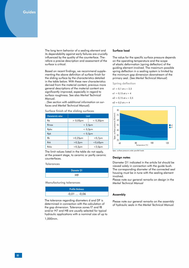
80
Guides
Characteristic value Limit
Ra > 0,05µm < 0,30µm
Rmax < 2,5µm
Rpkx < 0,5µm
Rpk < 0,5µm
Rk >0,25µm <0,7µm
Rvk >0,2µm <0,65µm
Rvkx >0,2µm <2,0µm
Manufacturing tolerances
Profile thickness
-0,01 ... -0,06
Surface finish of the sliding surfaces
The limit values listed in the table do not apply, at the present stage, to ceramic or partly ceramic counterfaces.
The value for the specific surface pressure depends on the operating temperature and the scope of elastic deformation (spring deflection) of the guiding element involved. The maximum possible spring deflection in a sealing system is limited by the minimum gap dimension downstream of the primary seal. (See Merkel Technical Manual)
Spec. surface pressure under parallel loads
e1 = 0,1 at s = 2,5
e1 = 0,15 at s = 4
e2 = 0,15 at s = 2,5
e2 = 0,2 at s = 4
The long term behavior of a sealing element and its dependability against early failures are crucially influenced by the quality of the counterface. The-refore a precise description and assessment of the surface is critical.
Based on recent findings, we recommend supple-menting the above definition of surface finish for the sliding surface by the characteristics detailed in the table below. With these new characteristics derived from the material content, previous more general descriptions of the material content are significantly improved, especially in regard to surface roughness. See also Merkel Technical Manual. . (See section with additional information on sur-faces and Merkel Technical Manual).
Diameter D1
H9
The tolerance regarding diameters d and DF is determined in connection with the calculation of the gap dimension. Tolerance zones f7 and f8 and/or H7 and H8 are usually selected for typical hydraulic applications with a nominal size of up to
1,000mm.
Diameter D1 indicated in the article list should be viewed solely in connection with the guide bush. The corresponding diameter of the connected seal housing must be in tune with the sealing element involved.Please note our general remarks on design in the Merkel Technical Manual
Assembly
Please note our general remarks on the assembly of hydraulic seals in the Merkel Technical Manual.
Surface load
Spring deflection
Design notes
Tolerances
Spec
. sur
face
pre
ssur
e (N
/mm
2 )
Temperature (°C)
Guides

81
Side load
Side loads within the contact area between the guide and the counter surface are not linear. The guiding width required can be calculated by ap-plying the formulas indicated below on the basis of the projected area. The non-linear progression
F = P x AA = d x HH = F / (d x P)
H = Guide bandwidth [mm]F = Radial loads [N]
A = Projected area [mm²]
Operating principle
Rectangular guide bushes:Stress peaks within the edge area
Guivex guide bush:uniform stress distribution
P = perm. surface pressure [N/mm²]d = Rod diameter with rod guide; Piston diameter with piston guide [mm]
of side load pressures is taken into account in the contact pressure value. It may be advisable to reduce the loads by selec-ting a broader guide in individual cases to obtain an extended service life.

82
Additional product description – Guide strips
Side load
The use of guide elements makes it possible to achieve low-friction and low-wear between the moving components of a hydraulic cylinder. Any side loads emerging during operation are ab-sorbed effectively and any metal to metal contact between the piston rod and/or the piston barrel and the surrounding housing components is precluded.The scope of the maximum side load is essentially determined by the geometrical marginal con-ditions and the properties of the guide element involved.
Excessive stresses
The guide play and elastic deformation of the ele-ments under load results in an angular deviation between the piston rod and/or the piston barrel and the counter surfaceduring operation. Con-sequently, guides inside hydraulic cylinders will not remain parallel, but primarily stressed at the edges.In this case, the permissible side load of the guide is defined by the lower maximum load up to edge break and not by the maximum compressive strength of the material. Excessive stresses within the edge area (Figure 01) make the penetration of lubricating media more difficult, too. The hydraulic medium is wiped along the edge stressed on the guide element and the lubricating film is reduced to a minimum, thus leading to stick-slip effects and greater wear.
Profiling
Guivex guide bushes are provided with a convex profiling oriented towards the groove base. The side load applied is distributed evenly over the width of the guide element here. The maximum contact pressure value remains within the medium range and stress peaks on the edges are reduced (Figure 02).
Sliding properties
Guivex guide bushes made of HGW HG517 and HGW HG 650 materials are compounded with graphite and/or PTFE in order to achieve a better dry-running behavior. As a result, guide bushes made of resin bonded fabric exhibit excellent sliding properties, due to the material properties alone, even in the event of inappropriate lubrica-tion. The absorption of lubricating media within the area comprised between the guide and the coun-ter surfaceis greatly enhanced by the patented profiling of Guivex guide bushes. Consequent-ly, the sliding behavior is also improved by the Guivex geometry with correspondingly positive ef-fects in terms of service life and stick-slip behavior.
Figure 01: Rectangular guide bushExcessive stress within the edge area
Figure 02: Guivex guide bushUniform stress distribution
Guides

83
Radial load capacity
Merkel resin bonded fabric materials are cha-racterized by a high degree of load capacity.
The impact of the operating temperature on the load capacity of resin bonded fabric guide bushes is restricted, of course, when using duroplastic resin bonded fabric quality HGW HG517. The resin matrix of our material HGW HG650 includes both duroplastic and thermoplastic constituents. If permissible side loads are simultaneously less dependent on temperatures, the flexibility will be noticeably improved for assembly with small diameters.
Purely thermoplastic basic materials like polyester, for example, exhibit a temperature-dependent material behavior. Permissible cross loads are gre-atly reduced under the effect of rising operating temperatures. (See Figure 03).
Forces are always introduced within the medium range of the guide bush in conjunction with the patented Guivex geometry. The maximum per-missible cross load is not reduced here by excess stress at the edges. Uniform movements along the stroke, coupled with a high radial load capacity, can be achieved even in conjunction with short guide lengths and long-stroke cylinders with high angular offset to be expected.
The absorption of lubricating media within the area comprised between the guide and the counter surfaceis greatly enhanced by the patented profiling of Guivex guide bushes. Consequently, Guivex guide bushes exhibit a favorable frictional behavior with correspondi-ngly positive effects in terms of service life and stick-slip behavior.
Forces are always introduced within the mid-section of the guide bush. Uniform move-ments along the stroke, coupled with a high radial load capacity, can be achieved even in conjunction with short guide lengths and long-stroke cylinders with the large angular offset to be expected. The system of guides inside the hydraulic cylinder will not be inclined to jam over a short guide distance either.
The use of Guivex guide bushes makes a vital contribution to the functional reliability and dependability of hydraulic cylinders.
Figure 03: Resin bonded fabric materials in comparison of load capacity among plane-parallel guides depending on the opera-ting temperature involved.
60 °C 80 °C 100 °C 120 °C
Que
rlast
110
100
90
80
70
50
0
60
40
30
20
10
HGW HG 517HGW HG 650andereother
Side
load
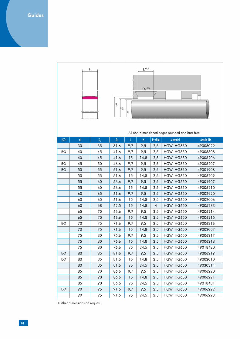
84
ISO d DF D1 L H Profile Material Article No.
30 35 31,6 9,7 9,5 2,5 HGW HG650 49006029
ISO 40 45 41,6 9,7 9,5 2,5 HGW HG650 49006608
40 45 41,6 15 14,8 2,5 HGW HG650 49006206
ISO 45 50 46,6 9,7 9,5 2,5 HGW HG650 49006207
ISO 50 55 51,6 9,7 9,5 2,5 HGW HG650 49001908
50 55 51,6 15 14,8 2,5 HGW HG650 49006209
55 60 56,6 9,7 9,5 2,5 HGW HG650 49001907
55 60 56,6 15 14,8 2,5 HGW HG650 49006210
60 65 61,6 9,7 9,5 2,5 HGW HG650 49002920
60 65 61,6 15 14,8 2,5 HGW HG650 49002006
60 68 62,5 15 14,8 4 HGW HG650 49005283
65 70 66,6 9,7 9,5 2,5 HGW HG650 49006214
65 70 66,6 15 14,8 2,5 HGW HG650 49006215
ISO 70 75 71,6 9,7 9,5 2,5 HGW HG650 49006216
70 75 71,6 15 14,8 2,5 HGW HG650 49002007
75 80 76,6 9,7 9,5 2,5 HGW HG650 49006217
75 80 76,6 15 14,8 2,5 HGW HG650 49006218
75 80 76,6 25 24,5 2,5 HGW HG650 49018480
ISO 80 85 81,6 9,7 9,5 2,5 HGW HG650 49006219
ISO 80 85 81,6 15 14,8 2,5 HGW HG650 49002010
80 85 81,6 25 24,5 2,5 HGW HG650 49030314
85 90 86,6 9,7 9,5 2,5 HGW HG650 49006220
85 90 86,6 15 14,8 2,5 HGW HG650 49006221
85 90 86,6 25 24,5 2,5 HGW HG650 49018481
ISO 90 95 91,6 9,7 9,5 2,5 HGW HG650 49006222
90 95 91,6 25 24,5 2,5 HGW HG650 49006223
Further dimensions on request.
All non-dimensioned edges rounded and burr-free
Guides
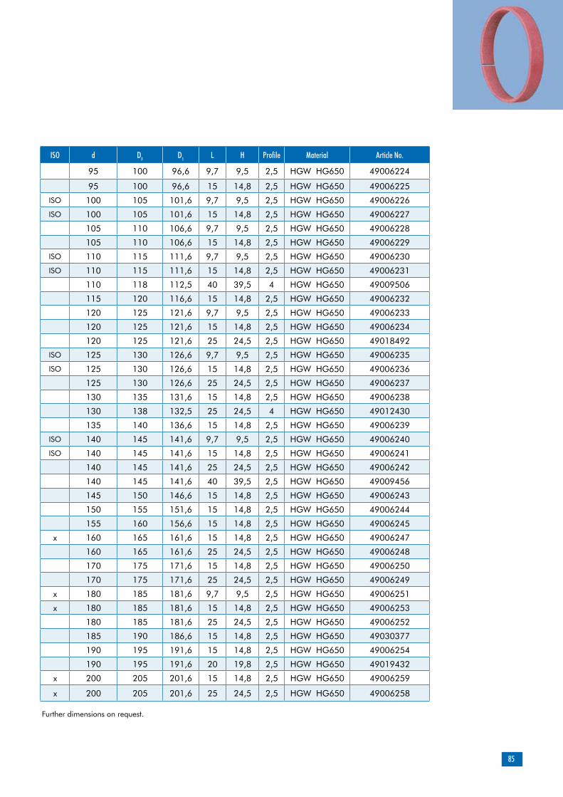
85
ISO d DF D1 L H Profile Material Article No.
95 100 96,6 9,7 9,5 2,5 HGW HG650 49006224
95 100 96,6 15 14,8 2,5 HGW HG650 49006225
ISO 100 105 101,6 9,7 9,5 2,5 HGW HG650 49006226
ISO 100 105 101,6 15 14,8 2,5 HGW HG650 49006227
105 110 106,6 9,7 9,5 2,5 HGW HG650 49006228
105 110 106,6 15 14,8 2,5 HGW HG650 49006229
ISO 110 115 111,6 9,7 9,5 2,5 HGW HG650 49006230
ISO 110 115 111,6 15 14,8 2,5 HGW HG650 49006231
110 118 112,5 40 39,5 4 HGW HG650 49009506
115 120 116,6 15 14,8 2,5 HGW HG650 49006232
120 125 121,6 9,7 9,5 2,5 HGW HG650 49006233
120 125 121,6 15 14,8 2,5 HGW HG650 49006234
120 125 121,6 25 24,5 2,5 HGW HG650 49018492
ISO 125 130 126,6 9,7 9,5 2,5 HGW HG650 49006235
ISO 125 130 126,6 15 14,8 2,5 HGW HG650 49006236
125 130 126,6 25 24,5 2,5 HGW HG650 49006237
130 135 131,6 15 14,8 2,5 HGW HG650 49006238
130 138 132,5 25 24,5 4 HGW HG650 49012430
135 140 136,6 15 14,8 2,5 HGW HG650 49006239
ISO 140 145 141,6 9,7 9,5 2,5 HGW HG650 49006240
ISO 140 145 141,6 15 14,8 2,5 HGW HG650 49006241
140 145 141,6 25 24,5 2,5 HGW HG650 49006242
140 145 141,6 40 39,5 2,5 HGW HG650 49009456
145 150 146,6 15 14,8 2,5 HGW HG650 49006243
150 155 151,6 15 14,8 2,5 HGW HG650 49006244
155 160 156,6 15 14,8 2,5 HGW HG650 49006245
x 160 165 161,6 15 14,8 2,5 HGW HG650 49006247
160 165 161,6 25 24,5 2,5 HGW HG650 49006248
170 175 171,6 15 14,8 2,5 HGW HG650 49006250
170 175 171,6 25 24,5 2,5 HGW HG650 49006249
x 180 185 181,6 9,7 9,5 2,5 HGW HG650 49006251
x 180 185 181,6 15 14,8 2,5 HGW HG650 49006253
180 185 181,6 25 24,5 2,5 HGW HG650 49006252
185 190 186,6 15 14,8 2,5 HGW HG650 49030377
190 195 191,6 15 14,8 2,5 HGW HG650 49006254
190 195 191,6 20 19,8 2,5 HGW HG650 49019432
x 200 205 201,6 15 14,8 2,5 HGW HG650 49006259
x 200 205 201,6 25 24,5 2,5 HGW HG650 49006258
Further dimensions on request.

86
ISO d DF D1 L H Profile Material Article No.
210 215 211,6 15 14,8 2,5 HGW HG650 49006260
ISO 220 225 221,6 15 14,8 2,5 HGW HG650 49006281
ISO 220 225 221,6 25 24,5 2,5 HGW HG650 49006282
230 235 231,6 15 14,8 2,5 HGW HG650 49006283
230 235 231,6 25 24,5 2,5 HGW HG650 49006284
235 240 236,6 15 14,8 2,5 HGW HG650 49023262
240 245 241,6 15 14,8 2,5 HGW HG650 49006285
ISO 250 255 251,6 15 14,8 2,5 HGW HG650 49006286
ISO 250 255 251,6 25 24,5 2,5 HGW HG650 49006287
270 275 271,6 25 24,5 2,5 HGW HG650 49006288
ISO 280 285 281,6 15 14,8 2,5 HGW HG650 49006290
ISO 280 285 281,6 25 24,5 2,5 HGW HG650 49006289
290 298 292,5 25 24,5 4 HGW HG650 49006291
300 308 302,5 25 24,5 4 HGW HG600 24380482
300 308 302,5 40 39,5 4 HGW HG600 24379155
310 315 311,6 15 14,8 2,5 HGW HG600 49030765
310 315 311,6 25 24,5 2,5 HGW HG600 49009463
320 325 321,6 15 14,8 2,5 HGW HG600 24380778
ISO 320 325 321,6 25 24,5 2,5 HGW HG600 24380272
320 325 321,6 30 29,5 2,5 HGW HG600 49023545
320 328 322,5 25 24,5 4 HGW HG600 24379076
320 328 322,5 30 29,5 4 HGW HG600 528486
320 328 322,5 40 39,5 4 HGW HG600 532132
330 335 331,6 25 24,5 2,5 HGW HG600 49012803
330 338 332,5 25 24,5 4 HGW HG600 24379040
340 345 341,6 15 14,8 2,5 HGW HG600 49017086
Further dimensions on request.
L+0,2H
DF
dD1
ØØ
Ø
1R <0,3
All non-dimensioned edges rounded and burr-free
Guides
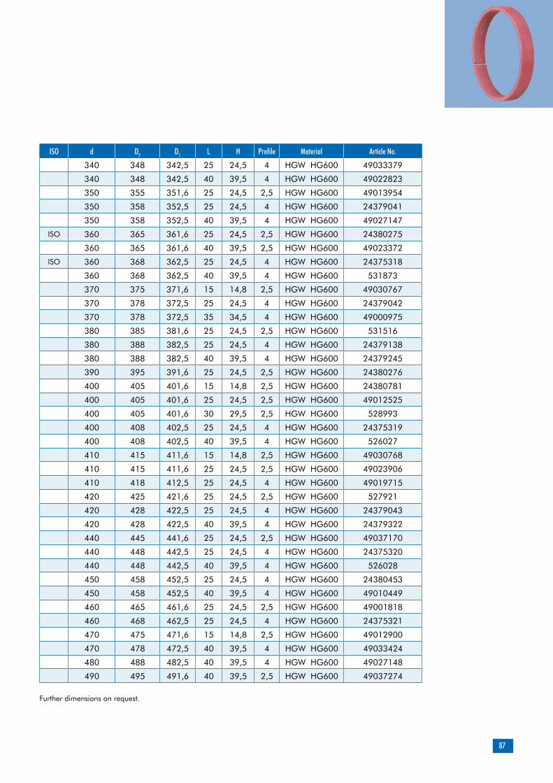
87
ISO d DF D1 L H Profile Material Article No.
340 348 342,5 25 24,5 4 HGW HG600 49033379
340 348 342,5 40 39,5 4 HGW HG600 49022823
350 355 351,6 25 24,5 2,5 HGW HG600 49013954
350 358 352,5 25 24,5 4 HGW HG600 24379041
350 358 352,5 40 39,5 4 HGW HG600 49027147
ISO 360 365 361,6 25 24,5 2,5 HGW HG600 24380275
360 365 361,6 40 39,5 2,5 HGW HG600 49023372
ISO 360 368 362,5 25 24,5 4 HGW HG600 24375318
360 368 362,5 40 39,5 4 HGW HG600 531873
370 375 371,6 15 14,8 2,5 HGW HG600 49030767
370 378 372,5 25 24,5 4 HGW HG600 24379042
370 378 372,5 35 34,5 4 HGW HG600 49000975
380 385 381,6 25 24,5 2,5 HGW HG600 531516
380 388 382,5 25 24,5 4 HGW HG600 24379138
380 388 382,5 40 39,5 4 HGW HG600 24379245
390 395 391,6 25 24,5 2,5 HGW HG600 24380276
400 405 401,6 15 14,8 2,5 HGW HG600 24380781
400 405 401,6 25 24,5 2,5 HGW HG600 49012525
400 405 401,6 30 29,5 2,5 HGW HG600 528993
400 408 402,5 25 24,5 4 HGW HG600 24375319
400 408 402,5 40 39,5 4 HGW HG600 526027
410 415 411,6 15 14,8 2,5 HGW HG600 49030768
410 415 411,6 25 24,5 2,5 HGW HG600 49023906
410 418 412,5 25 24,5 4 HGW HG600 49019715
420 425 421,6 25 24,5 2,5 HGW HG600 527921
420 428 422,5 25 24,5 4 HGW HG600 24379043
420 428 422,5 40 39,5 4 HGW HG600 24379322
440 445 441,6 25 24,5 2,5 HGW HG600 49037170
440 448 442,5 25 24,5 4 HGW HG600 24375320
440 448 442,5 40 39,5 4 HGW HG600 526028
450 458 452,5 25 24,5 4 HGW HG600 24380453
450 458 452,5 40 39,5 4 HGW HG600 49010449
460 465 461,6 25 24,5 2,5 HGW HG600 49001818
460 468 462,5 25 24,5 4 HGW HG600 24375321
470 475 471,6 15 14,8 2,5 HGW HG600 49012900
470 478 472,5 40 39,5 4 HGW HG600 49033424
480 488 482,5 40 39,5 4 HGW HG600 49027148
490 495 491,6 40 39,5 2,5 HGW HG600 49037274
Further dimensions on request.

88
ISO d DF D1 L H Profile Material Article No.
500 508 502,5 20 19,8 4 HGW HG600 24378392
500 508 502,5 25 24,5 4 HGW HG600 24375322
500 508 502,5 35 34,5 4 HGW HG600 49015387
500 508 502,5 40 39,5 4 HGW HG600 24379324
510 515 511,6 25 24,5 2,5 HGW HG600 49006851
510 518 512,5 25 24,5 4 HGW HG600 530266
520 525 521,6 30 29,5 2,5 HGW HG600 49015060
520 528 522,5 25 24,5 4 HGW HG600 49033459
520 528 522,5 40 39,5 4 HGW HG600 49008972
530 538 532,5 25 24,5 4 HGW HG600 24375323
530 538 532,5 40 39,5 4 HGW HG600 49004922
540 545 541,6 25 24,5 2,5 HGW HG600 49030392
540 548 542,5 40 39,5 4 HGW HG600 49018518
550 558 552,5 25 24,5 4 HGW HG600 49016779
550 558 552,5 40 39,5 4 HGW HG600 49005155
560 568 562,5 25 24,5 4 HGW HG600 24375324
570 578 572,5 25 24,5 4 HGW HG600 49017391
570 578 572,5 40 39,5 4 HGW HG600 49009448
580 588 582,5 40 39,5 4 HGW HG600 49015645
600 605 601,6 25 24,5 2,5 HGW HG600 528326
600 608 602,5 25 24,5 4 HGW HG600 24375325
600 608 602,5 40 39,5 4 HGW HG600 49003964
620 625 621,6 15 14,8 2,5 HGW HG600 49006971
620 628 622,5 25 24,5 4 HGW HG600 49027856
630 638 632,5 25 24,5 4 HGW HG600 524927
Further dimensions on request.
L+0,2H
DF
dD1
ØØ
Ø
1R <0,3
All non-dimensioned edges rounded and burr-free
Guides
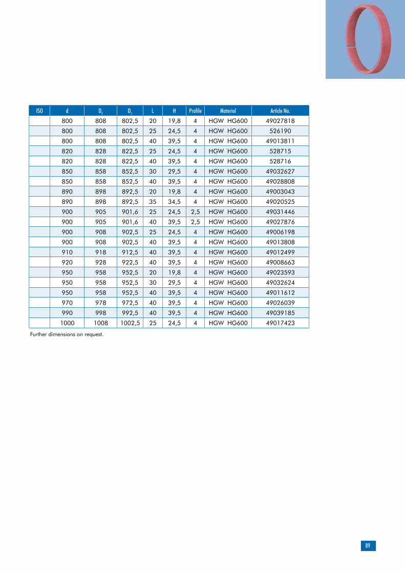
89
ISO d DF D1 L H Profile Material Article No.
800 808 802,5 20 19,8 4 HGW HG600 49027818
800 808 802,5 25 24,5 4 HGW HG600 526190
800 808 802,5 40 39,5 4 HGW HG600 49013811
820 828 822,5 25 24,5 4 HGW HG600 528715
820 828 822,5 40 39,5 4 HGW HG600 528716
850 858 852,5 30 29,5 4 HGW HG600 49032627
850 858 852,5 40 39,5 4 HGW HG600 49028808
890 898 892,5 20 19,8 4 HGW HG600 49003043
890 898 892,5 35 34,5 4 HGW HG600 49020525
900 905 901,6 25 24,5 2,5 HGW HG600 49031446
900 905 901,6 40 39,5 2,5 HGW HG600 49027876
900 908 902,5 25 24,5 4 HGW HG600 49006198
900 908 902,5 40 39,5 4 HGW HG600 49013808
910 918 912,5 40 39,5 4 HGW HG600 49012499
920 928 922,5 40 39,5 4 HGW HG600 49008663
950 958 952,5 20 19,8 4 HGW HG600 49023593
950 958 952,5 30 29,5 4 HGW HG600 49032624
950 958 952,5 40 39,5 4 HGW HG600 49011612
970 978 972,5 40 39,5 4 HGW HG600 49026039
990 998 992,5 40 39,5 4 HGW HG600 49039185
1000 1008 1002,5 25 24,5 4 HGW HG600 49017423
Further dimensions on request.

90
Product description
Product advantages
Applications
Merkel SF Guide Ring
Material
Material Designation Color
PTFE-bronze compound PTFE B500 brown
Non-metallic guide ring, either cut to size and ready for installation, or supplied as yard ware.
Non-metallic guide element for rods, for standar-dized housings as per ISO 10766, too low friction, stick-slip-free
Injection molding machines, control and regula-ting instruments, hand-held equipment
Design notes
Please note our general remarks on design in the Merkel Technical Manual.
L2 Manufacturing tolerance
>20 … 80 … 0,5
>80 … 250 … 1,0
>250 … 500 … 1,5
>500 … 1000 … 2,0
>1000 … 2000 … 3,0
>2000 … 4000 … 4,0
Peak-to-valley heights Ra Rmax
Sliding surface 0,05 … 0,3 µm <2,5 µm
Groove base <1,6 µm <6,3 µm
Groove sides <3,0 µm <15,0 µm
Material content Mr >50% to max. 90% with cut depth c = Rz/2 and reference line Cref = 0%
Surface finish
Manufacturing tolerance
Field of application
Merkel SF Guide Ring can be used in all hydraulic fluids normally found in hydraulic systems such as oils and greases based on mineral oils, fire-resistant hydraulic fluids (HFD) and biodegradable hydraulic fluids (HETG, HEES, HEPG). We do not recommend to used Guide Rings SF in water or water based fluids (HFA, HFB, HFC).The maximum permissible operating temperature is 120 °C
Guides

91
Recommended tolerances
D1
H8
The tolerance for dimensions d and DF must be viewed in connection with the seal used. Diameter D1 stated in the table of dimensions must be considered exclusively in conjunction with theguide ring. The corresponding diameter of the connected seal housing has to be adapted tothe sealing element involved.
Profile thickness
Profile thickness S
–0,05
Surface load
p <15 N/mm² … 20 °C
p <7,5 N/mm² … 80 °C
p <5 N/mm² … 120 °C
Sliding speed, see sealing system.
Cutting rolls to sizeThe dimensions indicated below are available as rolls ware from stock. Stretched length L2 of sections cut to size must be determined in line with the formula of calculation. Gap k arising after assembly is re-quired for thermal expansion purposes. We recommend therefore that the strips be cut straight. Butt joint tips may be damaged by fissures. Our cutter (article N. 507228) makes it possible to cut sections to size in a time-saving and accurate manner.
Calculating stretched length L2 for pistons: L2 = (d + S) x 3,11 – 0,5
H
D
d
S
L2
Groove length L Strip thickness S Article No.
8 2,5 24226174
9,7 2,5 24102775
10 2,5 24102563
12 2,5 24099191
15 2,5 24102564
20 2,5 24076217
25 2,5 24107955
15 4 24160019
20 4 24238052
25 4 24148093

92
Pressure distribution over guide rings is not linear. The non-linear pressure progression within the contact area has been duly taken into account when determining the permissible specific surface contact pressure value. Permissible loads for guide strips are calculated by multiplying the projected area with the permissible specific surface contact pressure value. However, the angular offset of the piston likely to arise when using the recommended guide elements is duly taken into consideration in the permissible specific surface contact pressure value mentioned here.
F = P x AA = d x HH = F / (d x P)
H = Guide bandwidth [mm]F = Radial loads [N]A = Projected area [mm²]P = Perm. surface pressing value [N/mm²]d = Rod diameter with rod guide; piston diameter with piston guide [mm].
Surface force
Guides
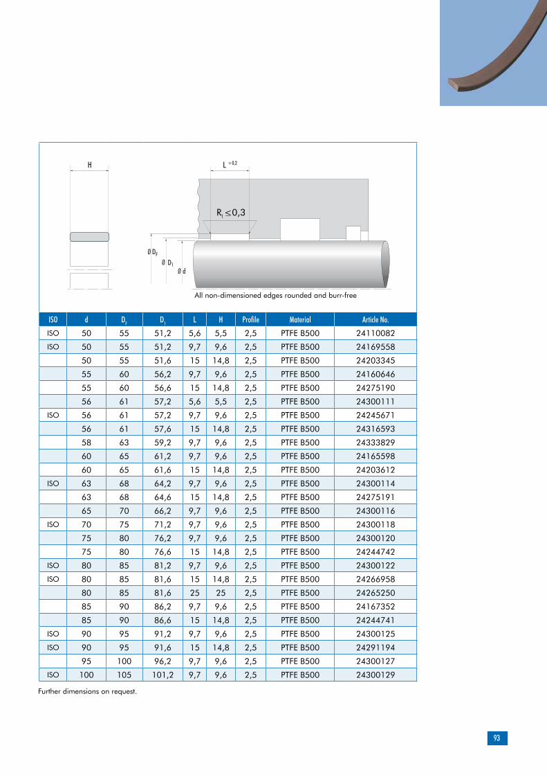
93
ISO d DF D1 L H Profile Material Article No.
ISO 50 55 51,2 5,6 5,5 2,5 PTFE B500 24110082
ISO 50 55 51,2 9,7 9,6 2,5 PTFE B500 24169558
50 55 51,6 15 14,8 2,5 PTFE B500 24203345
55 60 56,2 9,7 9,6 2,5 PTFE B500 24160646
55 60 56,6 15 14,8 2,5 PTFE B500 24275190
56 61 57,2 5,6 5,5 2,5 PTFE B500 24300111
ISO 56 61 57,2 9,7 9,6 2,5 PTFE B500 24245671
56 61 57,6 15 14,8 2,5 PTFE B500 24316593
58 63 59,2 9,7 9,6 2,5 PTFE B500 24333829
60 65 61,2 9,7 9,6 2,5 PTFE B500 24165598
60 65 61,6 15 14,8 2,5 PTFE B500 24203612
ISO 63 68 64,2 9,7 9,6 2,5 PTFE B500 24300114
63 68 64,6 15 14,8 2,5 PTFE B500 24275191
65 70 66,2 9,7 9,6 2,5 PTFE B500 24300116
ISO 70 75 71,2 9,7 9,6 2,5 PTFE B500 24300118
75 80 76,2 9,7 9,6 2,5 PTFE B500 24300120
75 80 76,6 15 14,8 2,5 PTFE B500 24244742
ISO 80 85 81,2 9,7 9,6 2,5 PTFE B500 24300122
ISO 80 85 81,6 15 14,8 2,5 PTFE B500 24266958
80 85 81,6 25 25 2,5 PTFE B500 24265250
85 90 86,2 9,7 9,6 2,5 PTFE B500 24167352
85 90 86,6 15 14,8 2,5 PTFE B500 24244741
ISO 90 95 91,2 9,7 9,6 2,5 PTFE B500 24300125
ISO 90 95 91,6 15 14,8 2,5 PTFE B500 24291194
95 100 96,2 9,7 9,6 2,5 PTFE B500 24300127
ISO 100 105 101,2 9,7 9,6 2,5 PTFE B500 24300129
Further dimensions on request.
L +0,2H
DF
dD1
ØØ
Ø
1R <0,3
All non-dimensioned edges rounded and burr-free
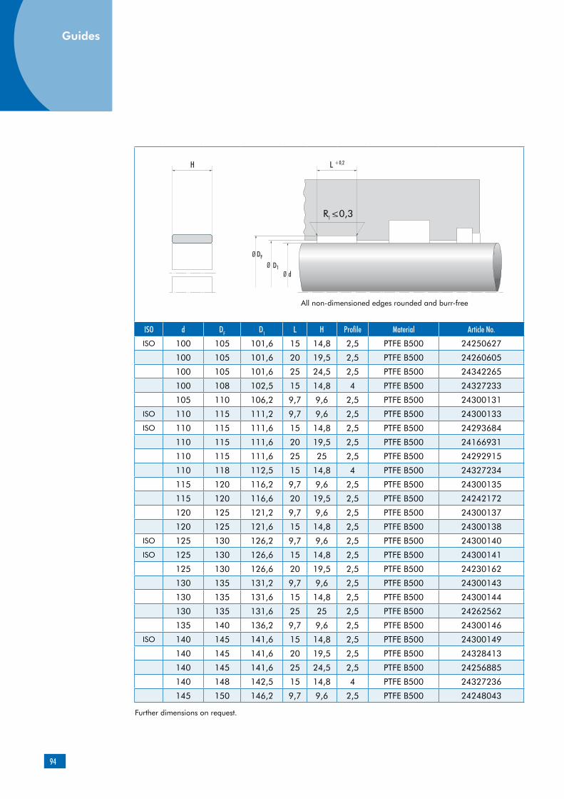
94
ISO d DF D1 L H Profile Material Article No.
ISO 100 105 101,6 15 14,8 2,5 PTFE B500 24250627
100 105 101,6 20 19,5 2,5 PTFE B500 24260605
100 105 101,6 25 24,5 2,5 PTFE B500 24342265
100 108 102,5 15 14,8 4 PTFE B500 24327233
105 110 106,2 9,7 9,6 2,5 PTFE B500 24300131
ISO 110 115 111,2 9,7 9,6 2,5 PTFE B500 24300133
ISO 110 115 111,6 15 14,8 2,5 PTFE B500 24293684
110 115 111,6 20 19,5 2,5 PTFE B500 24166931
110 115 111,6 25 25 2,5 PTFE B500 24292915
110 118 112,5 15 14,8 4 PTFE B500 24327234
115 120 116,2 9,7 9,6 2,5 PTFE B500 24300135
115 120 116,6 20 19,5 2,5 PTFE B500 24242172
120 125 121,2 9,7 9,6 2,5 PTFE B500 24300137
120 125 121,6 15 14,8 2,5 PTFE B500 24300138
ISO 125 130 126,2 9,7 9,6 2,5 PTFE B500 24300140
ISO 125 130 126,6 15 14,8 2,5 PTFE B500 24300141
125 130 126,6 20 19,5 2,5 PTFE B500 24230162
130 135 131,2 9,7 9,6 2,5 PTFE B500 24300143
130 135 131,6 15 14,8 2,5 PTFE B500 24300144
130 135 131,6 25 25 2,5 PTFE B500 24262562
135 140 136,2 9,7 9,6 2,5 PTFE B500 24300146
ISO 140 145 141,6 15 14,8 2,5 PTFE B500 24300149
140 145 141,6 20 19,5 2,5 PTFE B500 24328413
140 145 141,6 25 24,5 2,5 PTFE B500 24256885
140 148 142,5 15 14,8 4 PTFE B500 24327236
145 150 146,2 9,7 9,6 2,5 PTFE B500 24248043
Further dimensions on request.
L +0,2H
DF
dD1
ØØ
Ø
1R <0,3
All non-dimensioned edges rounded and burr-free
Guides

95
ISO d DF D1 L H Profile Material Article No.
195 200 196,2 9,7 9,6 2,5 PTFE B500 24242182
ISO 200 205 201,6 15 14,8 2,5 PTFE B500 24154721
200 205 201,6 25 25 2,5 PTFE B500 24266925
200 208 202,5 25 24,5 4 PTFE B500 24299021
210 215 211,2 9,7 9,6 2,5 PTFE B500 24300159
210 215 211,6 15 14,8 2,5 PTFE B500 24300160
210 215 211,6 20 19,5 2,5 PTFE B500 24239042
ISO 220 225 221,2 9,7 9,6 2,5 PTFE B500 24300161
ISO 220 225 221,6 15 14,8 2,5 PTFE B500 24300162
220 225 221,6 20 19,5 2,5 PTFE B500 24157304
230 235 231,6 15 14,8 2,5 PTFE B500 24154716
230 235 231,6 20 19,5 2,5 PTFE B500 24342108
240 245 241,2 9,7 9,7 2,5 PTFE B500 24258216
240 245 241,6 15 14,8 2,5 PTFE B500 24223045
240 245 241,6 25 24,5 2,5 PTFE B500 24314554
245 250 246,6 25 24,5 2,5 PTFE B500 24311377
ISO 250 255 251,6 15 14,8 2,5 PTFE B500 24300163
260 265 261,6 15 14,8 2,5 PTFE B500 24300164
270 275 271,6 25 25 2,5 PTFE B500 24262561
ISO 280 285 281,6 15 14,8 2,5 PTFE B500 24300166
290 295 291,6 15 14,8 2,5 PTFE B500 24300167
300 305 301,6 15 14,8 2,5 PTFE B500 24300168
300 305 301,6 25 24,5 2,5 PTFE B500 24348072
310 315 311,6 15 14,8 2,5 PTFE B500 24300169
325 330 326,6 25 25 2,5 PTFE B500 24293821
330 335 331,6 15 14,8 2,5 PTFE B500 24300172
330 335 331,6 25 24,5 2,5 PTFE B500 24300173
340 345 341,6 15 14,8 2,5 PTFE B500 24300174
340 345 341,6 25 24,5 2,5 PTFE B500 24162997
350 355 351,6 15 14,8 2,5 PTFE B500 24300175
350 355 351,6 25 24,5 2,5 PTFE B500 24300176
350 358 352,5 25 24,5 4 PTFE B500 24337998
x 360 365 361,6 15 14,8 2,5 PTFE B500 24300177
360 368 362,5 25 24,5 4 PTFE B500 24342011
390 395 391,6 15 14,8 2,5 PTFE B500 24350238
390 395 391,6 25 24,5 2,5 PTFE B500 24336658
390 398 392,5 25 24,5 4 PTFE B500 24355839
400 405 401,6 15 15 2,5 PTFE B500 24274959
Further dimensions on request.

96
ISO d DF D1 L H Profile Material Article No.
330 335 331,6 25 24,5 2,5 PTFE B500 24300173
340 345 341,6 15 14,8 2,5 PTFE B500 24300174
340 345 341,6 25 24,5 2,5 PTFE B500 24162997
350 355 351,6 15 14,8 2,5 PTFE B500 24300175
350 355 351,6 25 24,5 2,5 PTFE B500 24300176
350 358 352,5 25 24,5 4 PTFE B500 24337998
ISO 360 365 361,6 15 14,8 2,5 PTFE B500 24300177
360 368 362,5 25 24,5 4 PTFE B500 24342011
390 395 391,6 15 14,8 2,5 PTFE B500 24350238
390 395 391,6 25 24,5 2,5 PTFE B500 24336658
390 398 392,5 25 24,5 4 PTFE B500 24355839
400 405 401,6 15 15 2,5 PTFE B500 24274959
400 408 402,5 25 24,5 4 PTFE B500 24269425
410 415 411,6 25 25 2,5 PTFE B500 24296901
420 425 421,6 20 19,5 2,5 PTFE B500 24230161
420 425 421,6 25 24,5 2,5 PTFE B500 24233817
420 428 422,5 25 24,5 4 PTFE B500 24269684
425 430 426,6 25 25 2,5 PTFE B500 24261535
430 435 431,6 20 19,5 2,5 PTFE B500 24203171
430 435 431,6 25 24,5 2,5 PTFE B500 24348071
435 440 436,6 25 24,5 2,5 PTFE B500 24162988
440 445 441,6 25 24,5 2,5 PTFE B500 24344261
450 455 451,6 15 14,8 2,5 PTFE B500 24265878
450 455 451,6 25 25 2,5 PTFE B500 24257338
450 458 452,5 25 24,5 4 PTFE B500 24294991
460 465 461,6 25 24,5 2,5 PTFE B500 24308715
Further dimensions on request.
L +0,2H
DF
dD1
ØØ
Ø
1R <0,3
All non-dimensioned edges rounded and burr-free
Guides

97
ISO d DF D1 L H Profile Material Article No.
520 525 521,6 20 20 2,5 PTFE B500 24242786
540 545 541,6 0 24,5 2,5 PTFE B500 24358194
540 548 542,5 25 24,5 4 PTFE B500 24332687
550 555 551,6 25 24,5 2,5 PTFE B500 24344262
560 568 562,5 25 24,5 4 PTFE B500 24274998
570 575 571,5 25 25 2,5 PTFE B500 24263227
580 588 582,5 25 24,5 4 PTFE B500 24307426
590 595 591,6 25 25 2,5 PTFE B500 24290939
600 605 601,6 15 14,8 2,5 PTFE B500 24316132
600 605 601,6 20 19,5 2,5 PTFE B500 24300403
600 608 602,5 25 24,5 4 PTFE B500 24354936
620 625 621,6 20 19,5 2,5 PTFE B500 24291416
620 625 621,6 25 24,5 2,5 PTFE B500 24354129
630 635 631,6 20 19,5 2,5 PTFE B500 24361332
630 635 631,6 25 25 2,5 PTFE B500 24263904
640 648 642,5 25 24,5 4 PTFE B500 24298429
650 658 652,5 25 24,5 4 PTFE B500 24293967
670 675 671,6 25 24,5 2,5 PTFE B500 24162996
670 678 672,5 25 24,5 4 PTFE B500 24361116
675 680 676,6 25 25 2,5 PTFE B500 24261537
700 705 701,6 15 14,8 2,5 PTFE B500 24234909
700 705 701,6 25 24,5 2,5 PTFE B500 24223046
700 708 702,5 30 30 4 PTFE B500 24262945
710 718 712,5 15 14,8 4 PTFE B500 24216172
720 728 722,5 25 24,5 4 PTFE B500 24359660
730 738 732,5 25 24,5 4 PTFE B500 24263632
735 740 736,6 25 24,5 2,5 PTFE B500 24163718
740 748 742,5 20 19,5 4 PTFE B500 24344397
740 748 742,5 25 24,5 4 PTFE B500 24243175
750 755 751,6 25 24,5 2,5 PTFE B500 24227972
790 798 792,5 25 24,5 4 PTFE B500 24351827
800 808 802,5 25 24,5 4 PTFE B500 24295216
800 805 801,6 25 24,5 2,5 PTFE B500 24162994
820 828 822,5 20 19,5 4 PTFE B500 24238051
830 838 832,5 25 24,5 4 PTFE B500 24344381
850 858 852,5 25 24,5 4 PTFE B500 24314615
890 898 892,5 15 15 4 PTFE B500 24263607
890 898 892,5 25 24,5 4 PTFE B500 24263885
Further dimensions on request.

98
ISO d DF D1 L H Profile Material Article No.
735 740 736,6 25 24,5 2,5 PTFE B500 24163718
740 748 742,5 20 19,5 4 PTFE B500 24344397
740 748 742,5 25 24,5 4 PTFE B500 24243175
750 755 751,6 25 24,5 2,5 PTFE B500 24227972
790 798 792,5 25 24,5 4 PTFE B500 24351827
800 808 802,5 25 24,5 4 PTFE B500 24295216
800 805 801,6 25 24,5 2,5 PTFE B500 24162994
820 828 822,5 20 19,5 4 PTFE B500 24238051
830 838 832,5 25 24,5 4 PTFE B500 24344381
850 858 852,5 25 24,5 4 PTFE B500 24314615
890 898 892,5 15 15 4 PTFE B500 24263607
890 898 892,5 25 24,5 4 PTFE B500 24263885
900 908 902,5 25 24,5 4 PTFE B500 24257241
950 958 952,5 25 24,5 4 PTFE B500 24233242
975 983 977,5 25 24,5 4 PTFE B500 24361413
Further dimensions on request.
L +0,2H
DF
dD1
ØØ
Ø
1R <0,3
All non-dimensioned edges rounded and burr-free
Guides

99
Product description
Product advantages
Merkel Guivex KBK Guide Bush
Profiled piston guide bush made of resin bonded fabric. Patented product design (patent No.: PCT/EP95/03874)
intended, among others, for standardized housings as per ISO 10766 interchangeable with current housings of type KB and KF high radial load capacity very good guide-length utilization based on uniform stress distribution enhanced penetration of lubricating media based on optimized stress distribution within the contact zone between the guide bush and the counter surface(favorable frictional behavior) reduced propensity for stick-slip excellent sliding behavior over a short guiding distance (no jamming)
Applications
Long-stroke cylinder (piston-rod deflection)Short guiding distance (piston tilting)Short stroke (inappropriate lubrication)Frictionally optimized sealing systemsReplacement for metallic guides
Material Designation Color
Resin bonded fabric HGW HG650 red
Resin bonded fabric HGW HG517 dark-gray
Field of application
Guivex guide bushes can be used in all hydraulic fluids normally found in hydraulic systems such as oils and greases based on mineral oils, water, fire-resistant hydraulic fluids (HFA, HFB, HFC, HFD) and biodegradable hydraulic fluids (HETG, HEES, HEPG).The maximum permissible operating temperature is 120 °C
Material
The choice of material depends on the diameter involved.
Peak-to-valley heights Ra Rmax
Sliding surface 0,05 … 0,3 µm ≤<2,5 µm
Groove base ≤<1,6 µm ≤<6,3 µm
Groove sides ≤<3,0 µm ≤<15,0 µm
Material content Mr >50% to max. 90% with cut depth c = Rz/2 and reference line Cref = 0%
Surface finish

100
The limit values listed in the table do not apply, at the present stage, to ceramic or partly ceramic counterfaces.
Characteristic value Limit
Ra > 0,05µm < 0,30µm
Rmax < 2,5µm
Rpkx < 0,5µm
Rpk < 0,5µm
Rk >0,25µm <0,7µm
Rvk >0,2µm <0,65µm
Rvkx >0,2µm <2,0µm
Surface finish of the sliding surfaces
Diameter d1 indicated in the table of dimensions should be viewed solely in connection with the guide bush. The corresponding diameter of the connected seal housing must be in tune with the sealing element involved.
Design notes
Surface load
The value for the specific surface pressure depen-ds on the operating temperature and the scope of elastic deformation (spring deflection) of the guiding element involved. The maximum possible spring deflection in a sealing system is limited by the minimum gap dimension downstream of the primary seal. (See also Merkel Technical Manual)
Spring deflection
e1 = 0,1 at s = 2,5
e1 = 0,15 at s = 4
e2 = 0,15 at s = 2,5
e2 = 0,2 at s = 4
The long term behavior of a sealing element and its dependability against early failures are crucially influenced by the quality of the counterface. The-refore a precise description and assessment of the surface is critical.
Based on recent findings, we recommend supple-menting the above definition of surface finish for the dynamic surface by the characteristics detailed in the table below. With these new characteristics derived from the material content, previous more general descriptions of the material content are significantly improved, especially in regard to sur-face roughness. See also Merkel Technical Manual.
Manufacturing tolerances
Profile thickness
-0,01 ... -0,06
Diameter D1
h9
The tolerance regarding diameters dF and D is determined in connection with the calculation of the gap dimension. Tolerance zones H7 and H8 and/or h7 and h8 are usually selected for typical hydraulic applications with a nominal size of up to 1,000mm.
Tolerances
Installation & assembly
Please note our general remarks on the installation of hydraulic seals in the Merkel Technical Manual.
Spec
. sur
face
pre
ssur
e (N
/mm
2 )
Temperature (°C)
Spec. surface pressure under parallel loads
Guides
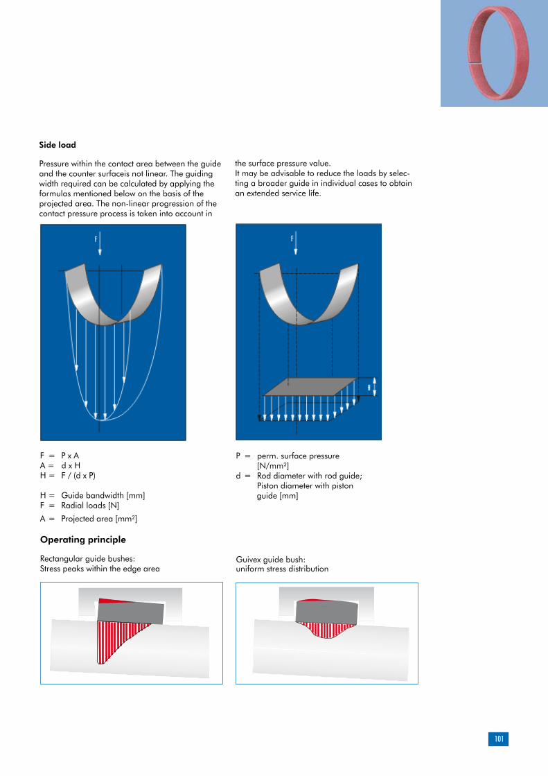
101
Side load
Pressure within the contact area between the guide and the counter surfaceis not linear. The guiding width required can be calculated by applying the formulas mentioned below on the basis of the projected area. The non-linear progression of the contact pressure process is taken into account in
F = P x AA = d x HH = F / (d x P)
H = Guide bandwidth [mm]F = Radial loads [N]
A = Projected area [mm²]
Operating principle
Rectangular guide bushes:Stress peaks within the edge area
Guivex guide bush:uniform stress distribution
P = perm. surface pressure [N/mm²]d = Rod diameter with rod guide; Piston diameter with piston guide [mm]
the surface pressure value. It may be advisable to reduce the loads by selec-ting a broader guide in individual cases to obtain an extended service life.

102
Additional product description – Guide strips
Side load
The use of guide elements makes it possible to achieve a low-friction and low-wear relative motion between the mobile components of the hydraulic cylinder. Any side loads arising duri-ng operation are absorbed effectively and any undesirable metal to metal contact between the piston rod and/or the piston barrel and the sur-rounding housing components is reduced.The scope of the maximum side load is essentially determined by the geometrical marginal con-ditions and the properties of the guide element involved.
Excessive stresses
The guide play and elastic deformation of the partners under loads result in an angular devi-ation between the piston rod and/or the piston barrel and the counter surfaceduring operation. Consequently, guides inside hydraulic cylinders will not be ideally parallel, but primarily stressed at the edges.In this case, the permissible side load of the guide is defined by the lower maximum load up to edge break and not by the maximum compressive strength of the material. Excessive stresses within the edge area (Figure 01) make the penetration of lubricating media more difficult, too. The hydraulic medium is wiped along the edge stressed on the guide element and the lubricating film is reduced to a minimum, thus leading to stick-slip effects and more significant wear.
Profiling
Guivex guide bushes are provided with a convex profiling oriented towards the groove base. The side load applied is distributed evenly over the width of the guide element here. The maximum contact pressure value remains within the medium range and excessive stresses are reduced at the edges (Figure 02).
Sliding properties
Guivex guide bushes made of HGW HG517 and HGW HG 650 materials are compounded with graphite and/or PTFE in order to achieve a better dry-running behavior. As a result, guide bushes made of resin bonded fabric exhibit excellent sliding properties, due to the material properties alone, even in the event of inappropriate lubrica-tion. The absorption of lubricating media within the area comprised between the guide and the coun-ter surfaceis greatly enhanced by the patented profiling of Guivex guide bushes. Consequent-ly, the sliding behavior is also improved by the Guivex geometry with correspondingly positive ef-fects in terms of service life and stick-slip behavior.
Figure 01: Rectangular guide bushExcessive stress within the edge area
Figure 02: Guivex guide bushUniform stress distribution
Guides

103
Radial load capacity
Merkel resin bonded fabric materials are cha-racterized by a high degree of radial load capa-city.
The impact of the operating temperature on the load capacity of resin bonded fabric guide bushes is restricted, of course, when using duroplastic resin bonded fabric quality HGW HG517. The resin matrix of our material HGW HG650 includes both duroplastic and thermoplastic constituents. If permissible cross loads are simultaneously less dependent on temperatures, the flexibility will be tangibly enhanced for assembly with small diameters.
Purely thermoplastic basic materials like polyester, for example, exhibit a temperature-dependent material behavior. Permissible cross loads are gre-atly reduced under the effect of rising operating temperatures. (See Figure 03).
Forces are always introduced within the medium range of the guide bush in conjunction with the patented Guivex geometry. The maximum per-missible cross load is not reduced here by excess stresses within the edge area. Uniform movements along the stroke, coupled with a high radial load capacity, can be achieved even in conjunction with short guide lengths and long-stroke cylinders with the large angular offset to be expected.
The absorption of lubricating media within the area comprised between the guide and the counter surfaceis greatly enhanced by the patented profiling of Guivex guide bushes. Consequently, Guivex guide bushes exhibit a favorable frictional behavior with correspondi-ngly positive effects in terms of service life and stick-slip behavior.
Forces are always introduced within the medi-um range of the guide bush. Uniform move-ments along the stroke, coupled with a high radial load capacity, can be achieved even in conjunction with short guide lengths and long-stroke cylinders with the large angular offset to be expected. The system of guides inside the hydraulic cylinder will not be inclined to jam over a short guide distance either.
The use of Guivex guide bushes makes a vital contribution to the functional reliability and dependability of hydraulic cylinders.
Figure 03: Resin bonded fabric materials in comparison of load capacity among plane-parallel guides depending on the operating temperature involved.
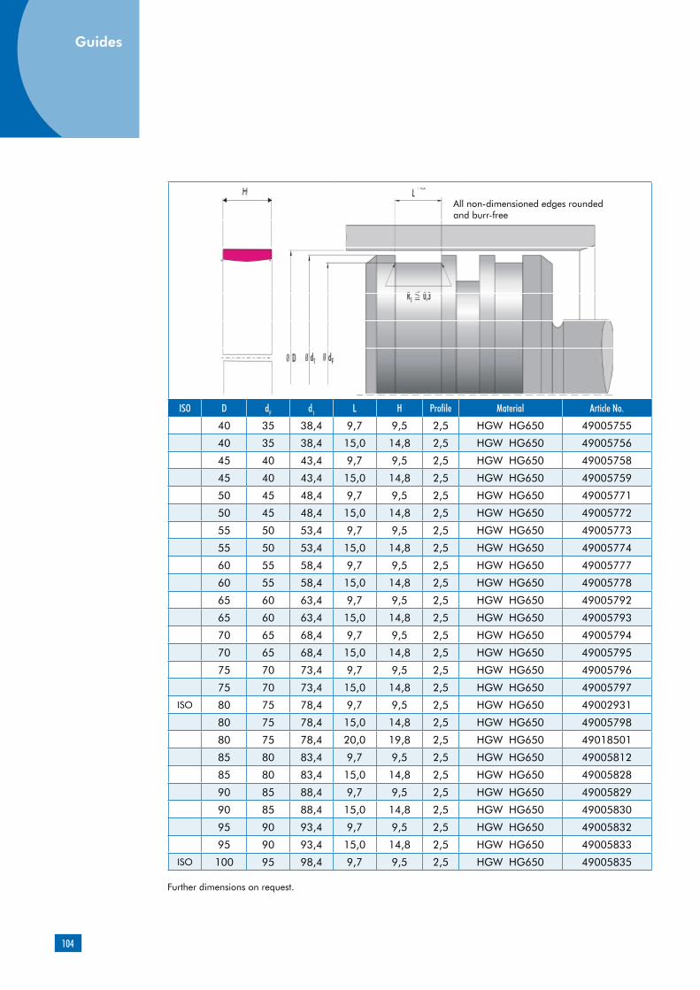
104
ISO D dF d1 L H Profile Material Article No.
40 35 38,4 9,7 9,5 2,5 HGW HG650 49005755
40 35 38,4 15,0 14,8 2,5 HGW HG650 49005756
45 40 43,4 9,7 9,5 2,5 HGW HG650 49005758
45 40 43,4 15,0 14,8 2,5 HGW HG650 49005759
50 45 48,4 9,7 9,5 2,5 HGW HG650 49005771
50 45 48,4 15,0 14,8 2,5 HGW HG650 49005772
55 50 53,4 9,7 9,5 2,5 HGW HG650 49005773
55 50 53,4 15,0 14,8 2,5 HGW HG650 49005774
60 55 58,4 9,7 9,5 2,5 HGW HG650 49005777
60 55 58,4 15,0 14,8 2,5 HGW HG650 49005778
65 60 63,4 9,7 9,5 2,5 HGW HG650 49005792
65 60 63,4 15,0 14,8 2,5 HGW HG650 49005793
70 65 68,4 9,7 9,5 2,5 HGW HG650 49005794
70 65 68,4 15,0 14,8 2,5 HGW HG650 49005795
75 70 73,4 9,7 9,5 2,5 HGW HG650 49005796
75 70 73,4 15,0 14,8 2,5 HGW HG650 49005797
ISO 80 75 78,4 9,7 9,5 2,5 HGW HG650 49002931
80 75 78,4 15,0 14,8 2,5 HGW HG650 49005798
80 75 78,4 20,0 19,8 2,5 HGW HG650 49018501
85 80 83,4 9,7 9,5 2,5 HGW HG650 49005812
85 80 83,4 15,0 14,8 2,5 HGW HG650 49005828
90 85 88,4 9,7 9,5 2,5 HGW HG650 49005829
90 85 88,4 15,0 14,8 2,5 HGW HG650 49005830
95 90 93,4 9,7 9,5 2,5 HGW HG650 49005832
95 90 93,4 15,0 14,8 2,5 HGW HG650 49005833
ISO 100 95 98,4 9,7 9,5 2,5 HGW HG650 49005835
Further dimensions on request.
All non-dimensioned edges rounded and burr-free
Guides
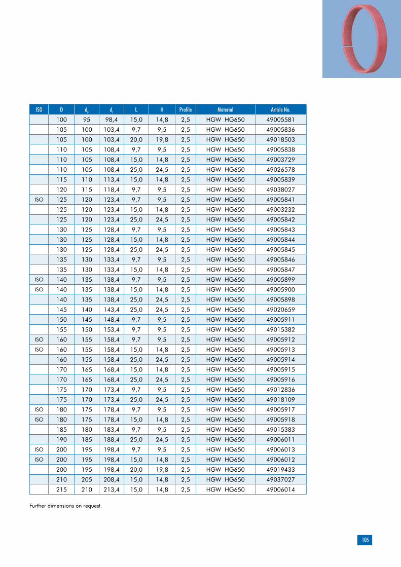
105
ISO D dF d1 L H Profile Material Article No.
100 95 98,4 15,0 14,8 2,5 HGW HG650 49005581
105 100 103,4 9,7 9,5 2,5 HGW HG650 49005836
105 100 103,4 20,0 19,8 2,5 HGW HG650 49018503
110 105 108,4 9,7 9,5 2,5 HGW HG650 49005838
110 105 108,4 15,0 14,8 2,5 HGW HG650 49003729
110 105 108,4 25,0 24,5 2,5 HGW HG650 49026578
115 110 113,4 15,0 14,8 2,5 HGW HG650 49005839
120 115 118,4 9,7 9,5 2,5 HGW HG650 49038027
ISO 125 120 123,4 9,7 9,5 2,5 HGW HG650 49005841
125 120 123,4 15,0 14,8 2,5 HGW HG650 49003232
125 120 123,4 25,0 24,5 2,5 HGW HG650 49005842
130 125 128,4 9,7 9,5 2,5 HGW HG650 49005843
130 125 128,4 15,0 14,8 2,5 HGW HG650 49005844
130 125 128,4 25,0 24,5 2,5 HGW HG650 49005845
135 130 133,4 9,7 9,5 2,5 HGW HG650 49005846
135 130 133,4 15,0 14,8 2,5 HGW HG650 49005847
ISO 140 135 138,4 9,7 9,5 2,5 HGW HG650 49005899
ISO 140 135 138,4 15,0 14,8 2,5 HGW HG650 49005900
140 135 138,4 25,0 24,5 2,5 HGW HG650 49005898
145 140 143,4 25,0 24,5 2,5 HGW HG650 49020659
150 145 148,4 9,7 9,5 2,5 HGW HG650 49005911
155 150 153,4 9,7 9,5 2,5 HGW HG650 49015382
ISO 160 155 158,4 9,7 9,5 2,5 HGW HG650 49005912
ISO 160 155 158,4 15,0 14,8 2,5 HGW HG650 49005913
160 155 158,4 25,0 24,5 2,5 HGW HG650 49005914
170 165 168,4 15,0 14,8 2,5 HGW HG650 49005915
170 165 168,4 25,0 24,5 2,5 HGW HG650 49005916
175 170 173,4 9,7 9,5 2,5 HGW HG650 49012836
175 170 173,4 25,0 24,5 2,5 HGW HG650 49018109
ISO 180 175 178,4 9,7 9,5 2,5 HGW HG650 49005917
ISO 180 175 178,4 15,0 14,8 2,5 HGW HG650 49005918
185 180 183,4 9,7 9,5 2,5 HGW HG650 49015383
190 185 188,4 25,0 24,5 2,5 HGW HG650 49006011
ISO 200 195 198,4 9,7 9,5 2,5 HGW HG650 49006013
ISO 200 195 198,4 15,0 14,8 2,5 HGW HG650 49006012
200 195 198,4 20,0 19,8 2,5 HGW HG650 49019433
210 205 208,4 15,0 14,8 2,5 HGW HG650 49037027
215 210 213,4 15,0 14,8 2,5 HGW HG650 49006014
Further dimensions on request.
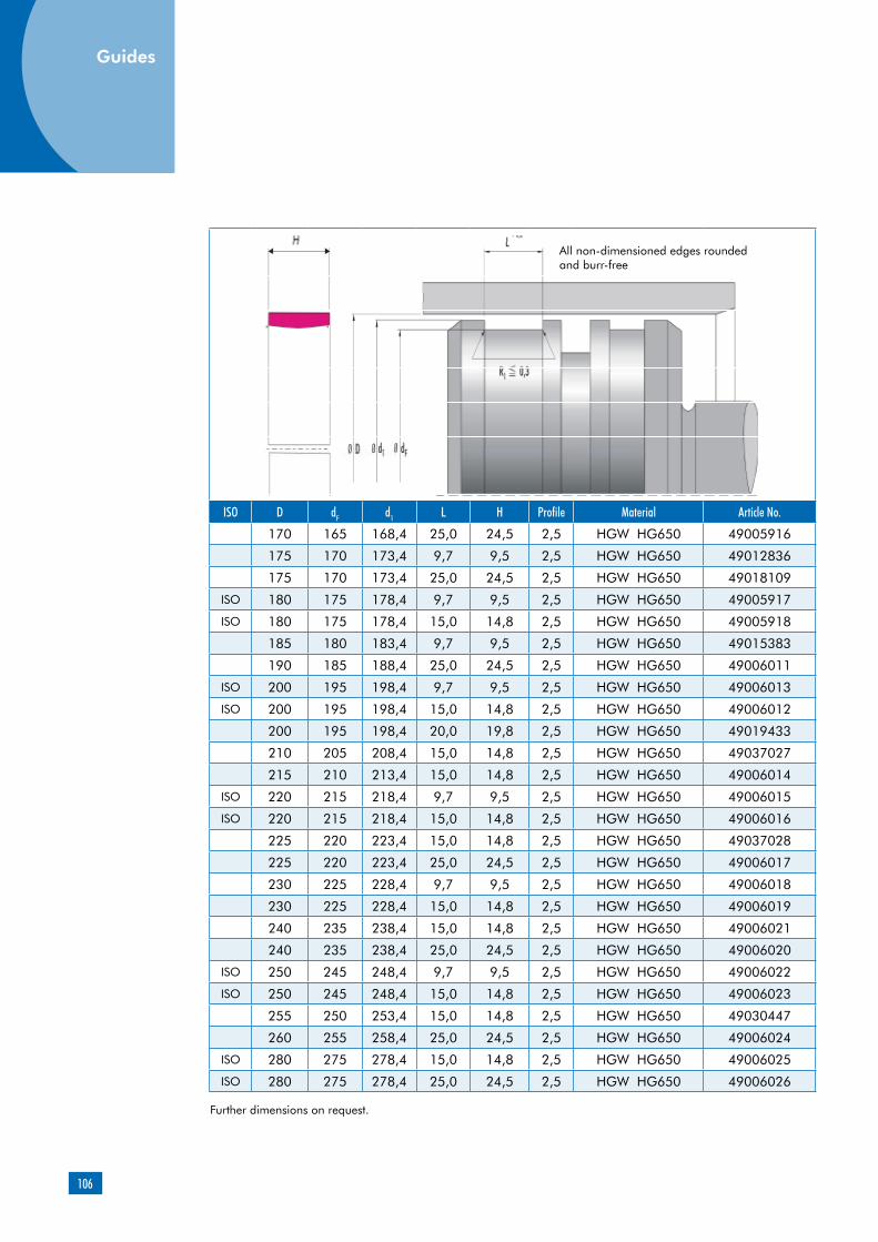
106
ISO D dF d1 L H Profile Material Article No.
170 165 168,4 25,0 24,5 2,5 HGW HG650 49005916
175 170 173,4 9,7 9,5 2,5 HGW HG650 49012836
175 170 173,4 25,0 24,5 2,5 HGW HG650 49018109
ISO 180 175 178,4 9,7 9,5 2,5 HGW HG650 49005917
ISO 180 175 178,4 15,0 14,8 2,5 HGW HG650 49005918
185 180 183,4 9,7 9,5 2,5 HGW HG650 49015383
190 185 188,4 25,0 24,5 2,5 HGW HG650 49006011
ISO 200 195 198,4 9,7 9,5 2,5 HGW HG650 49006013
ISO 200 195 198,4 15,0 14,8 2,5 HGW HG650 49006012
200 195 198,4 20,0 19,8 2,5 HGW HG650 49019433
210 205 208,4 15,0 14,8 2,5 HGW HG650 49037027
215 210 213,4 15,0 14,8 2,5 HGW HG650 49006014
ISO 220 215 218,4 9,7 9,5 2,5 HGW HG650 49006015
ISO 220 215 218,4 15,0 14,8 2,5 HGW HG650 49006016
225 220 223,4 15,0 14,8 2,5 HGW HG650 49037028
225 220 223,4 25,0 24,5 2,5 HGW HG650 49006017
230 225 228,4 9,7 9,5 2,5 HGW HG650 49006018
230 225 228,4 15,0 14,8 2,5 HGW HG650 49006019
240 235 238,4 15,0 14,8 2,5 HGW HG650 49006021
240 235 238,4 25,0 24,5 2,5 HGW HG650 49006020
ISO 250 245 248,4 9,7 9,5 2,5 HGW HG650 49006022
ISO 250 245 248,4 15,0 14,8 2,5 HGW HG650 49006023
255 250 253,4 15,0 14,8 2,5 HGW HG650 49030447
260 255 258,4 25,0 24,5 2,5 HGW HG650 49006024
ISO 280 275 278,4 15,0 14,8 2,5 HGW HG650 49006025
ISO 280 275 278,4 25,0 24,5 2,5 HGW HG650 49006026
Further dimensions on request.
All non-dimensioned edges rounded and burr-free
Guides

107
Further dimensions on request.
ISO D dF d1 L H Profile Material Article No.
300 295 298,4 15,0 14,8 2,5 HGW HG600 49008915
300 295 298,4 25,0 24,5 2,5 HGW HG600 24378787
310 305 308,4 15,0 14,8 2,5 HGW HG600 24380701
310 302 307,5 40,0 39,6 4 HGW HG600 24378053
ISO 320 312 317,5 25,0 24,5 4 HGW HG600 24379044
320 315 318,4 30,0 29,5 2,5 HGW HG600 49037777
320 312 317,5 40,0 39,6 4 HGW HG600 24378054
330 325 328,4 15,0 14,8 2,5 HGW HG600 49013266
330 325 328,4 25,0 24,5 2,5 HGW HG600 24379256
330 322 327,5 25,0 24,5 4 HGW HG600 49026460
330 322 327,5 30,0 29,5 4 HGW HG600 49004578
340 332 337,5 25,0 24,5 4 HGW HG600 24379045
340 332 337,5 30,0 29,5 4 HGW HG600 528485
350 345 348,4 15,0 14,8 2,5 HGW HG600 49023908
350 342 347,5 25,0 24,5 4 HGW HG600 530277
350 342 347,5 40,0 39,5 4 HGW HG600 533359
ISO 360 355 358,4 25,0 24,5 2,5 HGW HG600 49038865
ISO 360 352 357,5 25,0 24,5 4 HGW HG600 531639
360 352 357,5 30,0 29,5 4 HGW HG600 24379154
360 352 357,5 40,0 39,6 4 HGW HG600 24378056
365 357 362,5 25,0 24,5 4 HGW HG600 49006184
375 370 373,4 25,0 24,5 2,5 HGW HG600 24378788
375 367 372,5 25,0 24,5 4 HGW HG600 24379080
380 372 377,5 25,0 24,5 4 HGW HG600 49028909
380 372 377,5 40,0 39,5 4 HGW HG600 24378057
385 380 383,4 25,0 24,5 2,5 HGW HG600 49026710
390 385 388,4 15,0 14,8 2,5 HGW HG600 49023299
395 390 393,4 15,0 14,8 2,5 HGW HG600 49023907
400 392 397,5 40,0 39,5 4 HGW HG600 24378058
410 402 407,5 40,0 39,5 4 HGW HG600 531871
420 415 418,4 25,0 24,5 2,5 HGW HG600 49027578
420 412 417,5 25,0 24,5 4 HGW HG600 24379046
420 412 417,5 40,0 39,5 4 HGW HG600 24378059
430 422 427,5 40,0 39,5 4 HGW HG600 49003308
435 430 433,4 15,0 14,8 2,5 HGW HG600 49023909
440 432 437,5 25,0 24,5 4 HGW HG600 49002762
440 432 437,5 40,0 39,5 4 HGW HG600 49015384
450 442 447,5 40,0 39,5 4 HGW HG600 49027733

108
ISO D dF d1 L H Profile Material Article No.
455 447 452,5 25,0 24,5 4 HGW HG600 49026663
460 455 458,4 15,0 14,8 2,5 HGW HG600 49033429
460 455 458,4 25,0 24,5 2,5 HGW HG600 49038866
460 452 457,5 25,0 24,5 4 HGW HG600 24379348
460 452 457,5 40,0 39,6 4 HGW HG600 24379244
465 460 463,4 40,0 39,5 2,5 HGW HG600 49016011
470 465 468,4 25,0 24,5 2,5 HGW HG600 49018190
475 470 473,4 25,0 24,5 2,5 HGW HG600 49015956
480 475 478,4 25,0 24,5 2,5 HGW HG600 24378805
480 472 477,5 40,0 39,6 4 HGW HG600 24378060
ISO 500 492 497,5 25,0 24,5 4 HGW HG600 49002908
500 492 497,5 40,0 39,5 4 HGW HG600 531874
510 505 508,4 25,0 24,5 2,5 HGW HG600 49027823
510 502 507,5 25,0 24,5 4 HGW HG600 49022889
520 515 518,4 40,0 39,5 2,5 HGW HG600 49037275
530 522 527,5 25,0 24,5 4 HGW HG600 530276
530 522 527,5 40,0 39,5 4 HGW HG600 49012255
540 535 538,4 25,0 24,5 2,5 HGW HG600 24378806
540 532 537,5 25,0 24,5 4 HGW HG600 24379047
540 532 537,5 40,0 39,5 4 HGW HG600 49010048
550 545 548,4 25,0 24,5 2,5 HGW HG600 49006853
560 552 557,5 40,0 39,5 4 HGW HG600 49002673
565 557 562,5 40,0 39,5 4 HGW HG600 49027672
580 572 577,5 20,0 19,8 4 HGW HG600 49016127
580 572 577,5 40,0 39,5 4 HGW HG600 49015385
590 585 588,4 25,0 24,5 2,5 HGW HG600 49022694
Further dimensions on request.
All non-dimensioned edges rounded and burr-free
Guides

109
ISO D dF d1 L H Profile Material Article No.
600 595 598,4 25,0 24,5 2,5 HGW HG600 24378808
600 592 597,5 25,0 24,5 4 HGW HG600 24377999
600 592 597,5 40,0 39,5 4 HGW HG600 24379323
610 602 607,5 40,0 39,5 4 HGW HG600 49033425
620 612 617,5 25,0 24,5 4 HGW HG600 49004662
630 625 628,4 25,0 24,5 2,5 HGW HG600 49032298
630 622 627,5 40,0 39,5 4 HGW HG600 49002675
640 632 637,5 25,0 24,5 4 HGW HG600 531869
650 642 647,5 40,0 39,5 4 HGW HG600 49007593
660 655 658,4 25,0 24,5 2,5 HGW HG600 49012009
660 652 657,5 25,0 24,5 4 HGW HG600 49024947
680 675 678,4 25,0 24,5 2,5 HGW HG600 526191
680 672 677,5 25,0 24,5 4 HGW HG600 527133
680 672 677,5 40,0 39,5 4 HGW HG600 49004923
690 685 688,4 15,0 14,8 2,5 HGW HG600 49006972
700 692 697,5 35,0 34,5 4 HGW HG600 49003965
700 695 698,4 40,0 39,5 2,5 HGW HG600 49023373
710 702 707,5 40,0 39,5 4 HGW HG600 49002676
730 722 727,5 40,0 39,5 4 HGW HG600 49015648
740 732 737,5 25,0 24,5 4 HGW HG600 49023910
740 732 737,5 35,0 34,5 4 HGW HG600 24378498
750 742 747,5 25,0 24,5 4 HGW HG600 49019714
760 752 757,5 40,0 39,5 4 HGW HG600 24379321
800 792 797,5 20,0 19,8 4 HGW HG600 49000238
800 792 797,5 25,0 24,5 4 HGW HG600 24378000
830 822 827,5 25,0 24,5 4 HGW HG600 49023911
840 832 837,5 25,0 24,5 4 HGW HG600 49005727
850 842 847,5 25,0 24,5 4 HGW HG600 531637
865 857 862,5 20,0 19,8 4 HGW HG600 531678
865 857 862,5 40,0 39,5 4 HGW HG600 49003031
900 892 897,5 40,0 39,5 4 HGW HG600 49013810
950 942 947,5 25,0 24,5 4 HGW HG600 24379050
950 942 947,5 40,0 39,5 4 HGW HG600 49028807
965 957 962,5 25,0 24,5 4 HGW HG600 49003044
1000 992 997,5 40,0 39,5 4 HGW HG600 49013809
Further dimensions on request.

110
Product description
Product advantages
Applications
Merkel KF Guide Ring
Material
Material Designation Color
PTFE-bronze com-pound
PTFE B500 brown
Non-metallic guide ring, either cut to size and ready for installation, or supplied as rolls.
Non-metallic guide element for pistons, for stan-dardized housings as per ISO 10766, too low friction, stick-slip-free
Injection molding machines, control and regula-ting instruments, hand-held equipment
Design notes
Please note our general remarks on design in the Merkel Technical Manual.
Manufacturing tolerance
L2 Manufacturing tolerances
>20 … 80 … 0,5
>80 … 250 … 1,0
>250 … 500 … 1,5
>500 … 1000 … 2,0
>1000 … 2000 … 3,0
>2000 … 4000 … 4,0
Peak-to-valley heights Ra Rmax
Sliding surface 0,05 … 0,3
µm<2,5 µm
Groove base <1,6 µm <6,3 µm
Groove sides <3,0 µm <15,0 µm
Material content Mr >50% to max. 90% with cut depth c = Rz/2 and reference line Cref = 0%
Surface finish
Field of application
Merkel KF Guide Rings can be used in all hydrau-lic fluids normally found in hydraulic systems such as oils and greases based on mineral oils, fire-resistant hydraulic fluids (HFD) and biodegradable hydraulic fluids (HETG, HEES, HEPG). We do not recommend to used Guide Rings SF in water or water based fluids (HFA, HFB, HFC).The maximum permissible operating temperature is 120 °C
Guides

111
Recommended tolerances
d1
h8
The tolerance for dimensions D and dF must be viewed in connection with the seal used. Diameter d1stated in the table of dimensions must be considered exclusively in conjunction with theguide ring. Thecorresponding diameter of the connected seal housing has to be adapted to the sealing element involved.
Profile thickness
Profile thickness S
–0,05
Surface load
p <15 N/mm² … 20 °C
p <7,5 N/mm² … 80 °C
p <5 N/mm² … 120 °C
Sliding speed, see sealing system.
Cutting rolls to sizeThe dimensions indicated below are available as rolls from stock. Stretched length L2 of sections cut to size must be determined in line with the formula of calculation. Gap k arising after assembly is required for thermal expansion purposes. We recommend therefore that the strips be cut straight. Butt joint tips may be damaged by fissures. Our cutter (article N. 507228) makes it possible to cut sections to size in a time-saving and accurate manner.
Calculating stretched length L2 for pistons: L2 = (D – S) x 3,11 – 0,5
H
D
d
S
L2
Groove length L Strip thickness S Article No.
8 2,5 24226174
9,7 2,5 24102775
10 2,5 24102563
12 2,5 24099191
15 2,5 24102564
20 2,5 24076217
25 2,5 24107955
15 4 24160019
20 4 24238052
25 4 24148093

112
Surface forcePressure within the contact area between the guide and the counter surfaceis not linear. The guiding width required can be calculated by applying the formulas mentioned below on the basis of the projected area. The non-linear progression of the contact pressure process is taken into account in the surface pressure value. It may be advisable to reduce the loads by selecting a broader guide in individual cases to obtain an extended service life.
F = P x AA = d x HH = F / (d x P)
H = Guide bandwidth [mm]F = Radial loads [N]
A = Projected area [mm²]
P = perm. surface pressure [N/mm²]d = Rod diameter with rod guide; Piston diameter with piston guide [mm]
Guides
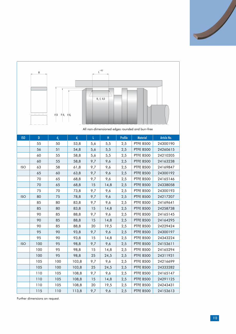
113
ISO D dF d1 L H Profile Material Article No.
55 50 53,8 5,6 5,5 2,5 PTFE B500 24300190
56 51 54,8 5,6 5,5 2,5 PTFE B500 24260615
60 55 58,8 5,6 5,5 2,5 PTFE B500 24210205
60 55 58,8 9,7 9,6 2,5 PTFE B500 24163238
ISO 63 58 61,8 9,7 9,6 2,5 PTFE B500 24169847
65 60 63,8 9,7 9,6 2,5 PTFE B500 24300192
70 65 68,8 9,7 9,6 2,5 PTFE B500 24165146
70 65 68,8 15 14,8 2,5 PTFE B500 24338058
75 70 73,8 9,7 9,6 2,5 PTFE B500 24300193
ISO 80 75 78,8 9,7 9,6 2,5 PTFE B500 24217207
85 80 83,8 9,7 9,6 2,5 PTFE B500 24169641
85 80 83,8 15 14,8 2,5 PTFE B500 24258738
90 85 88,8 9,7 9,6 2,5 PTFE B500 24165145
90 85 88,8 15 14,8 2,5 PTFE B500 24164295
90 85 88,8 20 19,5 2,5 PTFE B500 24229424
95 90 93,8 9,7 9,6 2,5 PTFE B500 24300197
95 90 93,8 15 14,8 2,5 PTFE B500 24343224
ISO 100 95 98,8 9,7 9,6 2,5 PTFE B500 24153611
100 95 98,8 15 14,8 2,5 PTFE B500 24165294
100 95 98,8 25 24,5 2,5 PTFE B500 24311931
105 100 103,8 9,7 9,6 2,5 PTFE B500 24216699
105 100 103,8 25 24,5 2,5 PTFE B500 24333282
110 105 108,8 9,7 9,6 2,5 PTFE B500 24165147
110 105 108,8 15 14,8 2,5 PTFE B500 24291125
110 105 108,8 20 19,5 2,5 PTFE B500 24243431
115 110 113,8 9,7 9,6 2,5 PTFE B500 24153613
Further dimensions on request.
H
d1D dF
L+0,2
R <= 0,31
Ø Ø Ø
All non-dimensioned edges rounded and burr-free
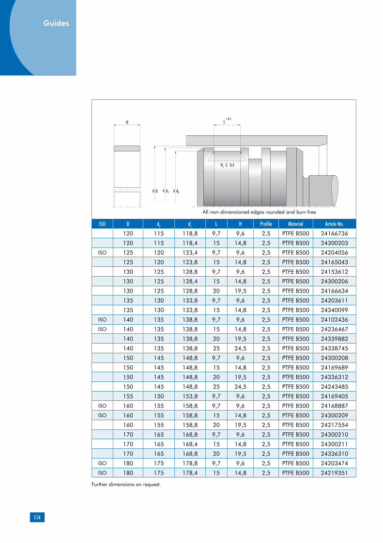
114
ISO D dF d1 L H Profile Material Article No.
120 115 118,8 9,7 9,6 2,5 PTFE B500 24166736
120 115 118,4 15 14,8 2,5 PTFE B500 24300203
ISO 125 120 123,4 9,7 9,6 2,5 PTFE B500 24204056
125 120 123,8 15 14,8 2,5 PTFE B500 24165043
130 125 128,8 9,7 9,6 2,5 PTFE B500 24153612
130 125 128,4 15 14,8 2,5 PTFE B500 24300206
130 125 128,8 20 19,5 2,5 PTFE B500 24166634
135 130 133,8 9,7 9,6 2,5 PTFE B500 24203611
135 130 133,8 15 14,8 2,5 PTFE B500 24340099
ISO 140 135 138,8 9,7 9,6 2,5 PTFE B500 24102436
ISO 140 135 138,8 15 14,8 2,5 PTFE B500 24236467
140 135 138,8 20 19,5 2,5 PTFE B500 24339882
140 135 138,8 25 24,5 2,5 PTFE B500 24338745
150 145 148,8 9,7 9,6 2,5 PTFE B500 24300208
150 145 148,8 15 14,8 2,5 PTFE B500 24169689
150 145 148,8 20 19,5 2,5 PTFE B500 24336312
150 145 148,8 25 24,5 2,5 PTFE B500 24243485
155 150 153,8 9,7 9,6 2,5 PTFE B500 24169405
ISO 160 155 158,8 9,7 9,6 2,5 PTFE B500 24168887
ISO 160 155 158,8 15 14,8 2,5 PTFE B500 24300209
160 155 158,8 20 19,5 2,5 PTFE B500 24217554
170 165 168,8 9,7 9,6 2,5 PTFE B500 24300210
170 165 168,4 15 14,8 2,5 PTFE B500 24300211
170 165 168,8 20 19,5 2,5 PTFE B500 24336310
ISO 180 175 178,8 9,7 9,6 2,5 PTFE B500 24203474
ISO 180 175 178,4 15 14,8 2,5 PTFE B500 24219351
Further dimensions on request.
H
d1D dF
L+0,2
R <= 0,31
Ø Ø Ø
All non-dimensioned edges rounded and burr-free
Guides

115
ISO D dF d1 L H Profile Material Article No.
220 215 218,4 25 24,5 2,5 PTFE B500 24290417
225 220 223,4 9,7 9,6 2,5 PTFE B500 24259939
225 220 223,4 15 14,8 2,5 PTFE B500 24169846
225 220 223,4 20 19,5 2,5 PTFE B500 24260604
225 220 223,4 25 24,5 2,5 PTFE B500 24298509
230 225 228,4 20 19,5 2,5 PTFE B500 24233567
240 235 238,4 15 14,8 2,5 PTFE B500 24167876
ISO 250 245 248,4 9,7 9,6 2,5 PTFE B500 24344263
ISO 250 245 248,4 15 14,8 2,5 PTFE B500 24300217
250 245 248,4 20 19,5 2,5 PTFE B500 24338719
260 255 258,4 15 14,8 2,5 PTFE B500 24300218
260 255 258,4 25 24,5 2,5 PTFE B500 24293567
270 265 268,4 15 14,8 2,5 PTFE B500 24238840
270 265 268,4 25 24,5 2,5 PTFE B500 24332002
ISO 280 275 278,4 15 14,8 2,5 PTFE B500 24300219
280 275 278,4 20 19,5 2,5 PTFE B500 24153362
ISO 280 275 278,4 25 24,5 2,5 PTFE B500 24203990
300 295 298,4 20 19,5 2,5 PTFE B500 24328393
300 295 298,4 15 14,8 2,5 PTFE B500 24137238
300 295 298,4 25 24,5 2,5 PTFE B500 24134951
305 300 303,4 15 14,8 2,5 PTFE B500 24350592
310 305 308,4 25 24,5 2,5 PTFE B500 24237194
320 312 317,5 20 19,5 4 PTFE B500 24245663
ISO 320 315 318,4 15 14,8 2,5 PTFE B500 24300220
320 315 318,4 20 19,5 2,5 PTFE B500 24231223
ISO 320 315 318,4 25 24,5 2,5 PTFE B500 24300221
330 325 328,4 15 14,8 2,5 PTFE B500 24296714
330 325 328,4 25 24,5 2,5 PTFE B500 24314011
340 335 338,4 15 14,8 2,5 PTFE B500 24300222
340 335 338,4 25 24,5 2,5 PTFE B500 24300223
350 345 348,4 9,7 9,6 2,5 PTFE B500 24316713
350 345 348,4 15 14,8 2,5 PTFE B500 24234725
355 350 353,4 25 24,5 2,5 PTFE B500 24336608
360 352 357,5 15 14,8 4 PTFE B500 24266168
x 360 352 357,5 25 24,5 4 PTFE B500 24298511
x 360 355 358,4 15 14,8 2,5 PTFE B500 24300224
x 360 355 358,4 25 24,5 2,5 PTFE B500 24164558
380 375 378,4 20 19,5 2,5 PTFE B500 24257157
Further dimensions on request.
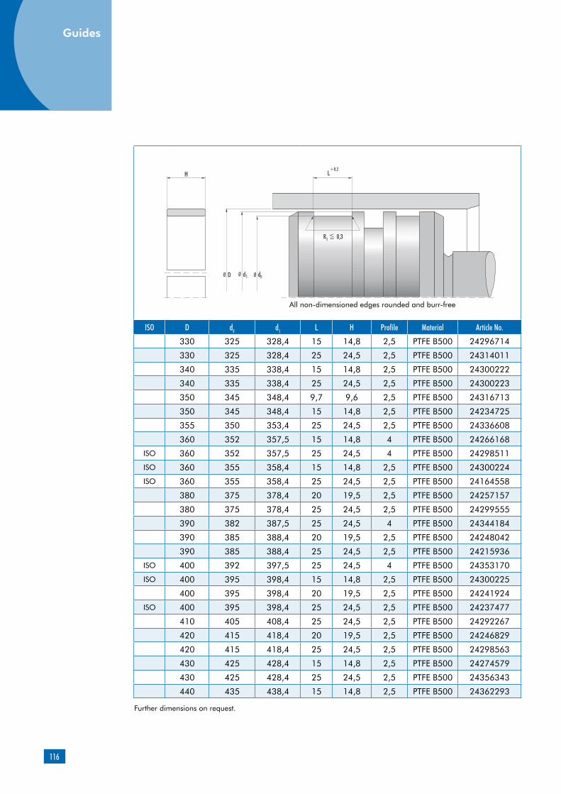
116
ISO D dF d1 L H Profile Material Article No.
330 325 328,4 15 14,8 2,5 PTFE B500 24296714
330 325 328,4 25 24,5 2,5 PTFE B500 24314011
340 335 338,4 15 14,8 2,5 PTFE B500 24300222
340 335 338,4 25 24,5 2,5 PTFE B500 24300223
350 345 348,4 9,7 9,6 2,5 PTFE B500 24316713
350 345 348,4 15 14,8 2,5 PTFE B500 24234725
355 350 353,4 25 24,5 2,5 PTFE B500 24336608
360 352 357,5 15 14,8 4 PTFE B500 24266168
ISO 360 352 357,5 25 24,5 4 PTFE B500 24298511
ISO 360 355 358,4 15 14,8 2,5 PTFE B500 24300224
ISO 360 355 358,4 25 24,5 2,5 PTFE B500 24164558
380 375 378,4 20 19,5 2,5 PTFE B500 24257157
380 375 378,4 25 24,5 2,5 PTFE B500 24299555
390 382 387,5 25 24,5 4 PTFE B500 24344184
390 385 388,4 20 19,5 2,5 PTFE B500 24248042
390 385 388,4 25 24,5 2,5 PTFE B500 24215936
ISO 400 392 397,5 25 24,5 4 PTFE B500 24353170
ISO 400 395 398,4 15 14,8 2,5 PTFE B500 24300225
400 395 398,4 20 19,5 2,5 PTFE B500 24241924
ISO 400 395 398,4 25 24,5 2,5 PTFE B500 24237477
410 405 408,4 25 24,5 2,5 PTFE B500 24292267
420 415 418,4 20 19,5 2,5 PTFE B500 24246829
420 415 418,4 25 24,5 2,5 PTFE B500 24298563
430 425 428,4 15 14,8 2,5 PTFE B500 24274579
430 425 428,4 25 24,5 2,5 PTFE B500 24356343
440 435 438,4 15 14,8 2,5 PTFE B500 24362293
Further dimensions on request.
H
d1D dF
L+0,2
R <= 0,31
Ø Ø Ø
All non-dimensioned edges rounded and burr-free
Guides

117
ISO D dF d1 L H Profile Material Article No.
ISO 500 492 497,5 25 24,5 4 PTFE B500 24261230
ISO 500 495 498,4 15 14,8 2,5 PTFE B500 24274580
ISO 500 495 498,4 25 24,5 2,5 PTFE B500 24263977
510 505 508,4 15 14,8 2,5 PTFE B500 24291161
510 505 508,4 25 24,5 2,5 PTFE B500 24360396
520 515 518,4 20 19,5 2,5 PTFE B500 24230163
530 525 528,4 15 14,8 2,5 PTFE B500 24258834
540 535 538,4 25 24,5 2,5 PTFE B500 24339008
545 540 543,4 25 24,5 2,5 PTFE B500 24250579
550 545 548,4 25 24,5 2,5 PTFE B500 24257339
560 552 557,5 25 24,5 4 PTFE B500 24359710
560 555 558,4 15 14,8 2,5 PTFE B500 24351466
560 555 558,4 25 24,5 2,5 PTFE B500 24269185
570 562 567,5 15 14,8 4 PTFE B500 24352095
570 562 567,5 25 24,5 4 PTFE B500 24351060
580 572 577,5 15 14,8 4 PTFE B500 24344267
580 575 578,4 25 24,5 2,5 PTFE B500 24339500
600 592 597,5 25 24,5 4 PTFE B500 24275000
600 595 598,4 15 14,8 2,5 PTFE B500 24234910
600 595 598,4 20 19,5 2,5 PTFE B500 24329803
600 595 598,4 25 24,5 2,5 PTFE B500 24234912
625 620 623,4 15 14,8 2,5 PTFE B500 24352637
630 625 628,4 15 14,8 2,5 PTFE B500 24161640
630 625 628,4 25 24,5 2,5 PTFE B500 24263466
640 632 637,5 25 24,5 4 PTFE B500 24275167
650 642 647,5 25 24,5 4 PTFE B500 24358984
650 645 648,4 25 24,5 2,5 PTFE B500 24239182
655 650 653,4 25 24,5 2,5 PTFE B500 24231930
665 660 663,4 25 24,5 2,5 PTFE B500 24336379
680 672 677,5 15 14,8 4 PTFE B500 24344269
680 672 677,5 25 24,5 4 PTFE B500 24298430
680 675 678,4 25 24,5 2,5 PTFE B500 24357190
690 682 687,5 25 24,5 4 PTFE B500 24361405
700 692 697,5 25 24,5 4 PTFE B500 24349705
700 695 698,4 15 14,8 2,5 PTFE B500 24275183
700 695 698,4 25 24,5 2,5 PTFE B500 24338859
710 705 708,4 20 19,5 2,5 PTFE B500 24162128
720 712 717,5 20 19,5 4 PTFE B500 24226253
Further dimensions on request.

118
ISO D dF d1 L H Profile Material Article No.
720 712 717,5 25 24,5 4 PTFE B500 24355876
720 715 718,4 15 14,8 2,5 PTFE B500 24348252
720 715 718,4 20 19,5 2,5 PTFE B500 24291417
720 715 718,4 25 24,5 2,5 PTFE B500 24240256
725 720 723,4 25 24,5 2,5 PTFE B500 24340198
750 742 747,5 25 24,5 4 PTFE B500 24293964
760 752 757,5 15 14,8 4 PTFE B500 24216171
760 752 757,5 20 19,5 4 PTFE B500 24216170
760 755 758,4 25 24,5 2,5 PTFE B500 24162992
770 762 767,5 15 14,8 4 PTFE B500 24344270
775 770 773,4 25 24,5 2,5 PTFE B500 24245794
780 775 778,4 15 14,8 2,5 PTFE B500 24358668
800 792 797,5 15 14,8 4 PTFE B500 24348279
800 792 797,5 25 24,5 4 PTFE B500 24243176
820 812 817,5 25 24,5 4 PTFE B500 24341042
830 822 827,5 25 24,5 4 PTFE B500 24354856
830 825 828,4 25 24,5 2,5 PTFE B500 24353637
850 842 847,5 25 24,5 4 PTFE B500 24300402
850 845 848,4 20 19,5 2,5 PTFE B500 24265124
850 845 848,4 25 24,5 2,5 PTFE B500 24163721
900 892 897,5 20 19,5 4 PTFE B500 24238053
900 892 897,5 25 24,5 4 PTFE B500 24344380
900 895 898,4 25 24,5 2,5 PTFE B500 24162990
920 915 918,4 25 24,5 2,5 PTFE B500 24258318
940 932 937,5 25 24,5 4 PTFE B500 24352164
940 935 938,4 25 24,5 2,5 PTFE B500 24163720
Further dimensions on request.
H
d1D dF
L+0,2
R <= 0,31
Ø Ø Ø
All non-dimensioned edges rounded and burr-free
Guides

119
Further dimensions on request.
ISO D dF d1 L H Profile Material Article No.
965 957 962,5 15 14,8 4 PTFE B500 24263608
965 957 962,5 25 24,5 4 PTFE B500 24295215
1000 995 998,4 25 24,5 2,5 PTFE B500 24162989
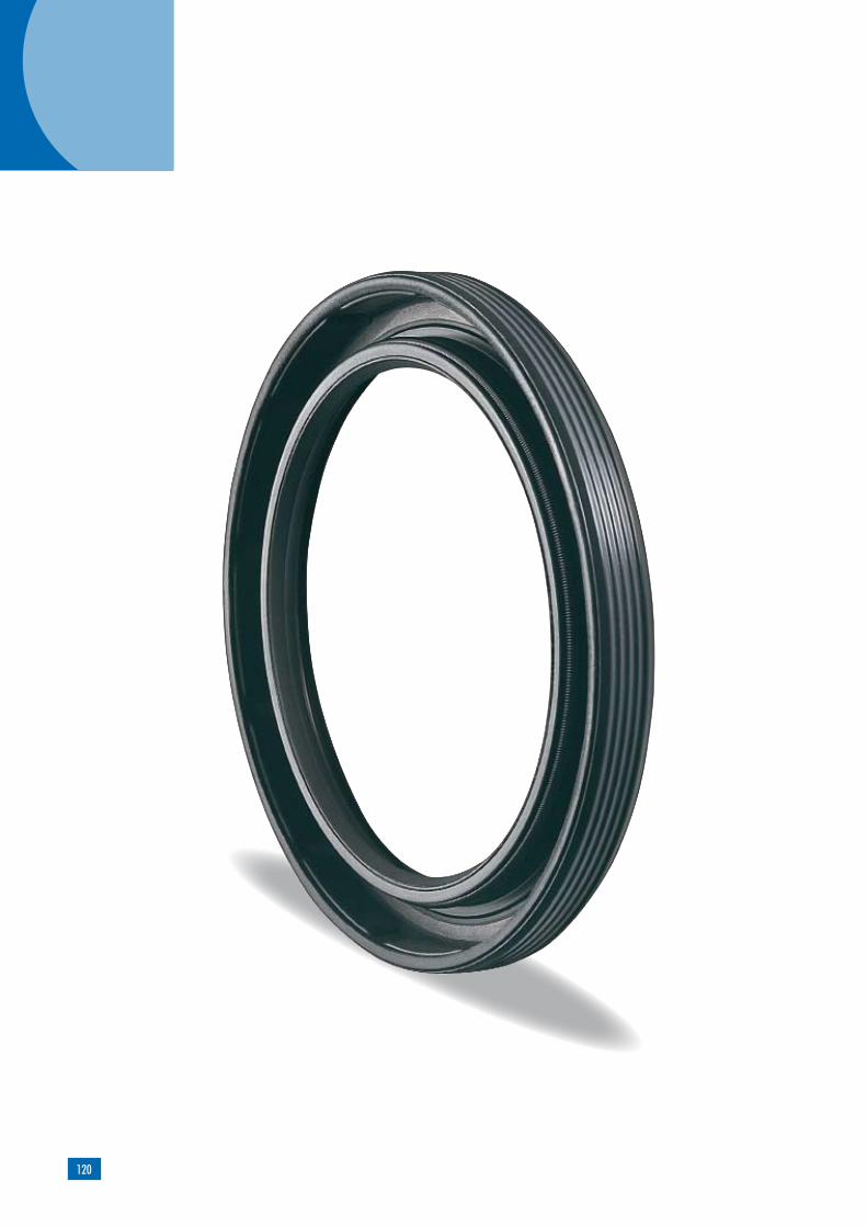
120

121
Product description
Product advantages
Fluoroelastomer
Designa-tion Color Hard-
ness Spring Reinforcing plate
75 FKM 585
dark-brown
Shore A 75 ore A
Spring steel DIN EN 10270-1
unalloyed steel DIN EN
10027-1
Applications
Simmerring BAUMSL X7
Agricultural and construction machineryIndustrial gearsAxles (exposed to moderate dirt influences)Electric tools
Material
Outer sleeve: elastomer, grooved, spring-loaded sealing lip, additional dust lip, frictionally opti-mized sealing lip profile.
broad application spectrum in all branches of industrygreater thermal stability and chemical resistanceSecure OD sealing, even in the event of higher bore roughness, thermal expansion and spilt housings, so that fluid and gaseous media can be sealed, too.advantages for sealing against fluid and gase-ous mediaadditional dust lip protecting against reasona-ble and average volumes of dust and dirt from outside (note: may lead to higher temperatures as a result of frictional heat)
Shaft seals
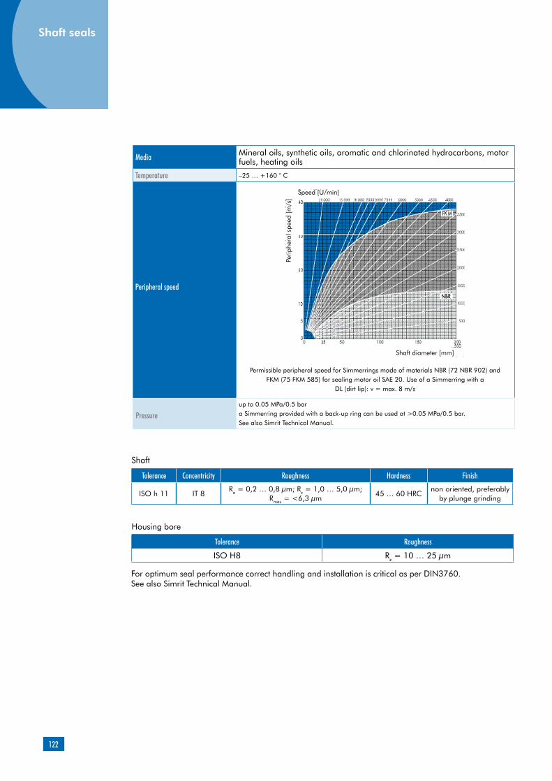
122
Shaft seals
Media Mineral oils, synthetic oils, aromatic and chlorinated hydrocarbons, motor fuels, heating oils
–25 … +160 ° C
v
Permissible peripheral speed for Simmerrings made of materials NBR (72 NBR 902) and FKM (75 FKM 585) for sealing motor oil SAE 20. Use of a Simmerring with a
DL (dirt lip): v = max. 8 m/s
Pressureup to 0.05 MPa/0.5 bara Simmerring provided with a back-up ring can be used at >0.05 MPa/0.5 bar.See also Simrit Technical Manual.
Tolerance Concentricity Roughness Hardness Finish
ISO h 11 IT 8Ra = 0,2 … 0,8 µm; Rz = 1,0 … 5,0 µm;
Rmax = <6,3 µm45 … 60 HRC
non oriented, preferably by plunge grinding
Housing bore
Shaft
Tolerance Roughness
ISO H8 Rz = 10 … 25 µm
Temperature
Peripheral speed
For optimum seal performance correct handling and installation is critical as per DIN3760. See also Simrit Technical Manual.
Speed [U/min]
Shaft diameter [mm]
Perip
hera
l spe
ed [m
/s]
Shaft seals

123
d1 d2 b DIN 3761 Article No.
50 60 4,5 AS 52119450 65 8 AS 41018850 68 8 AS 43370850 72 8 AS 41043050 75 8 AS 46876050 80 8 AS 47766350 80 10 AS 40544750 80 10 AS 52623952 68 8 AS 40924452 72 8 AS 41042252 80 10 AS 53294052 85 10 AS 46536854 70 8 AS 53293955 68 8 AS 52086455 70 8 AS 47638155 72 8 AS 40714055 75 8 AS 41078455 78 10 AS 47411155 80 8 AS 52100855 90 8 AS 47766255 110 10 AS 46536756 70 8 AS 40729656 72 8 AS 41042058 72 8 AS 4900950858 80 8 AS 47851460 75 8 AS 40432160 80 8 AS 40729460 90 8 AS 40744860 95 8 AS 468761
Further dimensions on request.
b
Ø d2 Ø d2
Ø d1 Ø d1
H8
h11
min=b + 0,3

124
d1 d2 b DIN 3761 Article No.
62 90 10 AS 52002963 90 10 AS 41041764 90 10 AS 53293865 80 8 AS 47410965 85 10 AS 38999965 90 10 AS 41624665 100 10 AS 41040867 90 10 AS 53179068 90 10 AS 40729170 85 8 AS 53295870 90 10 AS 52022670 95 12 AS 40544970 100 10 AS 52410572 100 10 AS 40728975 90 10 AS 46876275 95 10 AS 52100975 100 10 AS 40727975 115 12 AS 47766480 100 10 AS 46897880 110 10 AS 42769980 140 13 AS 47766685 100 8 AS 52022785 105 7 AS 52285085 105 12 AS 40432985 130 10 AS 47766785 150 12 AS 52010588 160 13 AS 47761190 110 12 AS 52101090 115 12 AS 428612
Further dimensions on request.
b
Ø d2 Ø d2
Ø d1 Ø d1
H8
h11
min=b + 0,3
Shaft seals

125
d1 d2 b DIN 3761 Article No.
110 140 12 AS 521013115 140 12 AS 522388115 150 12 AS 411270120 140 13 AS 405832120 150 12 AS 474123120 160 12 AS 411290122 200 15 AS 477613125 150 12 AS 407276130 160 12 AS 474122130 170 12 AS 411238130 200 15 AS 477612140 170 13 AS 434702150 180 15 AS 521014150 225 15 AS 477610155 180 15 AS 474107160 190 15 AS 521015160 240 14 AS 477614162 190 12 AS 520229170 200 15 AS 521016180 210 15 AS 521017190 220 15 AS 454176200 230 15 AS 520230210 240 15 AS 474108220 250 15 AS 468763230 260 15 AS 520231240 270 15 AS 520694250 280 15 AS 520695260 300 20 AS 520696280 320 20 AS 520697
300 340 20 AS 520698
320 360 20 AS 520699
340 380 20 AS 523042
Further dimensions on request.

126
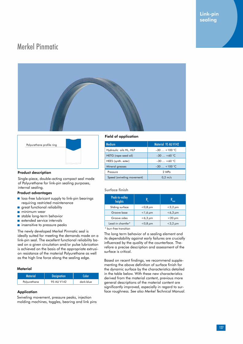
127
Merkel Pinmatic
Product description
Single-piece, double-acting compact seal made of Polyurethane for link-pin sealing purposes, internal sealing.Product advantages
Material
Application
Material Designation Color
Polyurethane 95 AU V142 dark-blue
loss-free lubricant supply to link-pin bearings requiring restricted maintenancegreat functional reliabilityminimum wear stable long-term behaviorextended service intervalsinsensitive to pressure peaks
Field of application
Swiveling movement, pressure peaks, injection molding machines, toggles, bearing and link pins
Polyurethane profile ring
The newly developed Merkel Pinmatic seal is ideally suited for meeting the demands made on a link-pin seal. The excellent functional reliability ba-sed on a given circulation and/or pulse lubrication is achieved on the basis of the appropriate extrusi-on resistance of the material Polyurethane as well as the high line force along the sealing edge.
Medium Material 95 AU V142
Hydraulic oils HL, HLP –30 … +100 °C
HETG (rape-seed oil) –30 … +60 °C
HEES (synth. ester) –30 … +60 °C
Mineral greases –30 … +100 °C
Pressure 2 MPa
Speed (swiveling movement) 0,2 m/s
The long term behavior of a sealing element and its dependability against early failures are crucially influenced by the quality of the counterface. The-refore a precise description and assessment of the surface is critical.
Based on recent findings, we recommend supple-menting the above definition of surface finish for the dynamic surface by the characteristics detailed in the table below. With these new characteristics derived from the material content, previous more general descriptions of the material content are significantly improved, especially in regard to sur-face roughness. See also Merkel Technical Manual.
Peak-to-valley heights Ra Rmax
Sliding surface <0,8 µm <3,2 µm
Groove base <1,6 µm <6,3 µm
Groove sides <6,3 µm <20 µm
Lead-in chamfer* <0,8 µm <3,2 µm
Surface finish
* burr-free transition
Link-pin sealing

128
Link-pin sealing
Link-pin sealing
Recommended tolerances
Surface finish of the sliding surfaces
Characteristic value Limit
Ra > 0,05µm < 0,30µm
Rmax < 2,5µm
Rpkx < 0,5µm
Rpk < 0,5µm
Rk >0,25µm <0,7µm
Rvk >0,2µm <0,65µm
Rvkx >0,2µm <2,0µm
Gap dimension
Section Max. permissible gap dimension at 2 MPa3,5 - 8,5 0,55
Diameter Tolerance< 200 H7/f7
Design notesPlease note our general design-related remarks in the Merkel Technical Manual.
Please note our general remarks on the installation of hydraulic seals in the Merkel Technical Manual, Assembling hydraulic seals.
Installation & assembly
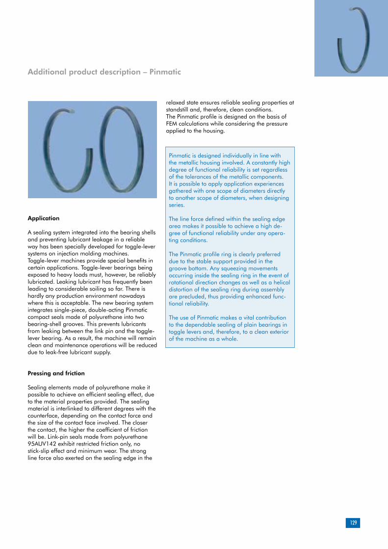
129
Application
A sealing system integrated into the bearing shells and preventing lubricant leakage in a reliable way has been specially developed for toggle-lever systems on injection molding machines. Toggle-lever machines provide special benefits in certain applications. Toggle-lever bearings being exposed to heavy loads must, however, be reliably lubricated. Leaking lubricant has frequently been leading to considerable soiling so far. There is hardly any production environment nowadays where this is acceptable. The new bearing system integrates single-piece, double-acting Pinmatic compact seals made of polyurethane into two bearing-shell grooves. This prevents lubricants from leaking between the link pin and the toggle-lever bearing. As a result, the machine will remain clean and maintenance operations will be reduced due to leak-free lubricant supply.
Pressing and friction
Sealing elements made of polyurethane make it possible to achieve an efficient sealing effect, due to the material properties provided. The sealing material is interlinked to different degrees with the counterface, depending on the contact force and the size of the contact face involved. The closer the contact, the higher the coefficient of friction will be. Link-pin seals made from polyurethane 95AUV142 exhibit restricted friction only, no stick-slip effect and minimum wear. The strong line force also exerted on the sealing edge in the
relaxed state ensures reliable sealing properties at standstill and, therefore, clean conditions. The Pinmatic profile is designed on the basis of FEM calculations while considering the pressure applied to the housing.
Additional product description – Pinmatic
Pinmatic is designed individually in line with the metallic housing involved. A constantly high degree of functional reliability is set regardless of the tolerances of the metallic components. It is possible to apply application experiences gathered with one scope of diameters directly to another scope of diameters, when designing series.
The line force defined within the sealing edge area makes it possible to achieve a high de-gree of functional reliability under any opera-ting conditions.
The Pinmatic profile ring is clearly preferred due to the stable support provided in the groove bottom. Any squeezing movements occurring inside the sealing ring in the event of rotational direction changes as well as a helical distortion of the sealing ring during assembly are precluded, thus providing enhanced func-tional reliability.
The use of Pinmatic makes a vital contribution to the dependable sealing of plain bearings in toggle levers and, therefore, to a clean exterior of the machine as a whole.
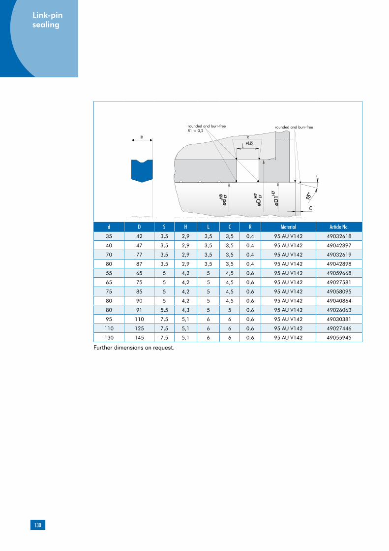
130
d D S H L C R Material Article No.
35 42 3,5 2,9 3,5 3,5 0,4 95 AU V142 49032618
40 47 3,5 2,9 3,5 3,5 0,4 95 AU V142 49042897
70 77 3,5 2,9 3,5 3,5 0,4 95 AU V142 49032619
80 87 3,5 2,9 3,5 3,5 0,4 95 AU V142 49042898
55 65 5 4,2 5 4,5 0,6 95 AU V142 49059668
65 75 5 4,2 5 4,5 0,6 95 AU V142 49027581
75 85 5 4,2 5 4,5 0,6 95 AU V142 49058095
80 90 5 4,2 5 4,5 0,6 95 AU V142 49040864
80 91 5,5 4,3 5 5 0,6 95 AU V142 49026063
95 110 7,5 5,1 6 6 0,6 95 AU V142 49030381
110 125 7,5 5,1 6 6 0,6 95 AU V142 49027446
130 145 7,5 5,1 6 6 0,6 95 AU V142 49055945
Further dimensions on request.
Link-pin sealing

131
Product description
Product advantages
interchangeable with housings for O-ring and O-ring with back-up ringhigh degree of functional reliability provided by the sturdy profile ring made of Polyurethanegreat resistance to extrusion (dimensional stability)simple and safe assembly (single-piece element)simplified inventorygastight
Material Designation ColorPolyurethane 95 AU V142 dark-blue
Polyurethane 94 AU 925 light-blue
Applications
Single-piece, double-acting compact seal made of Polyurethane for static sealing, inter-nal sealing.
Merkel Cover Seal PU 82
Material
High operating pressure (up to 60 MPa)
Breathing gap (cylinder expansion)
Short pressure build-up time (end-of-travel damping)
Reciprocal operating pressure
Nominal diameter up to 2,000mm
Polyurethane profile ring
Field of application
Material 95 AU V142/94 AU 925Hydraulic oils, HL, HLP -30 ... +110 °C
HFA fluids +5 ... +50 °C
HFB fluids +5 ... +50 °C
HFC fluids -30 ... +40 °C
HFD fluids -
Water +5 ... +40 °C
HETG (rape-seed oil) –30 … +60 °C
HEES (synth. ester) –30 … +60 °C
HEPG (glycol) –30 … +40 °C
Mineral greases –30 … +110 °C
Pressure 60 MPa
The figures given are maximum values and must not be applied simultaneously.
Peak-to-valley heights Ra Rmax
Sliding surface <0,8 µm <3,2 µm
Groove base <1,6 µm <6,3 µm
Groove sides <6,3 µm <20 µm
Lead-in chamfer* <0,8 µm <3,2 µm
Surface finish
* burr-free transition
Der Material wird durch den NennDiameter und das Fertigungsverfahren bestimmt. Section* Max. perm. gap dimension
16 MPa 26 MPa 32 MPa 40 MPa 60 MPa
1,78 0,2 0,2 0,15 0,1 0,1
2,62 0,35 0,3 0,25 0,15 0,1
3,5/3,53 0,5 0,4 0,35 0,25 0,2
5,33 0,5 0,4 0,35 0,25 0,2
6,99/7 0,55 0,45 0,35 0,35 0,25
8 0,55 0,45 0,4 0,35 0,25
8,4 0,55 0,45 0,4 0,35 0,25
10 0,6 0,5 0,45 0,4 0,3
12 0,6 0,5 0,45 0,4 0,3
The maximum permissible extrusion gap with a piston rod arranged on one side, while taking cy-linder expansion into account, is determined, to a large extent, by the maximum operating pressure and the dimensional stability of the sealing mate-rial, depending on the temperature involved.
* Cord thickness for housing recommendation O-ring with a back-up ring
Gap dimension

132
Static seal
Tolerances
Diameter d Tolerance
< 800 H7/f7
> 800 +0,1 / -0,05 / -0,15
Installation & assembly
Please note our general remarks in the Merkel Technical Manual.
Operating principle
Design notes
Please note our general remarks on the installation of hydraulic seals in the Merkel Technical Manual.
O-ring with a PTFE back-up ring at an operating pressure of 40 MPa
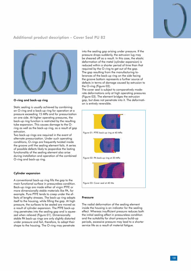
133
O-ring and back-up ring
Static sealing is usually achieved by combining an O-ring and a back-up ring for operation at a pressure exceeding 15 MPa and for pressurization on one side. At higher operating pressures, the back-up ring function is restricted by the resulting tube expansion. This causes damage to the O-ring as well as the back-up ring, as a result of gap extrusion. Two back-up rings are required in the event of alternate pressurization. Under such operating conditions, O-rings are frequently twisted inside the groove until the sealing element fails. A series of possible defects likely to jeopardize the lasting functionality of the sealing element also arise during installation and operation of the combined O-ring and back-up ring.
Cylinder expansion
A conventional back-up ring fills the gap to the main functional surface in pressureless condition. Back-up rings are made either of virgin PTFE or more dimensionally stable materials like PA, for example. Pure PTFE tends to creep under the ef-fects of lengthy stresses. The back-up ring adapts itself to the housing, while filling the gap. At high pressure, the surfaces to be sealed are moved as a result of cylinder expansion. The PTFE back-up ring penetrates into the sealing gap and is squee-zed when relieved (Figure 01). Dimensionally stable PA back-up rings are only slightly distorted under pressure and fail, therefore, to adapt their shape to the housing. The O-ring may penetrate
Additional product description – Cover Seal PU 82
into the sealing gap arising under pressure. If the pressure drops suddenly, the extrusion lug may be sheared off as a result. In this case, the elastic deformation of the metal (cylinder expansion) is reduced within a shorter period of time than that required by the O-ring to get out of the gap. The gap resulting from the manufacturing to-lerances of the back-up ring on the side facing the groove bottom represents a further source of defects in terms of damage caused by extrusion to the O-ring (Figure 02).The cover seal is subject to comparatively mode-rate deformations only at high operating pressures (Figure 03). The element bridges the extrusion gap, but does not penetrate into it. The deformati-on is entirely reversible.
Pressure
The radial deformation of the sealing element inside the housing is an indicator for the sealing effect. Whereas insufficient pressure reduces both the initial sealing effect in pressureless condition and the suitability for short pressure build-up periods, excessive pressure may lead to a shorter service life as a result of material fatigue.
Figure 01: PTFE back-up ring at 40 MPa
Figure 02: PA back-up ring at 20 MPa
Figure 03: Cover seal at 40 Ma

134
Static seal
The tolerances for metallic components and the seal exert a profound influence on profile overlap-ping. Whereas tolerance dimensions for metallic components are selected according to the nominal diameter involved, the cord thickness for an O-ring is given a constant tolerance regardless of the O-ring diameter. The larger the nominal diameter with the same cord thickness, the larger possible deviations from ideal pressure conditions will be. The sealing effect and/or the functional reliability of an O-ring will decline in proportion to nominal diameter increases.
The cover seal profile is adapted to the housing respectively involved, i.e. by taking the nominal diameter into consideration, too, on the basis of a design program and in view of the pressing con-ditions. Consequently, the diameter has no impact on the sealing effect and functional reliability.
The cover seal is designed individually in line with the metallic housing used. A continously high degree of functional reliability is set regar-dless of the tolerances of the metallic compo-nents and of the nominal diameter involved. It is possible to apply application experiences gathered with one scope of diameters directly to another scope of diameters, when designing series.
A high degree of functional reliability is at-tained under any operating conditions due to a great resistance to extrusion and a favorable mold release behavior, on the one hand, and to the high line force around the sealing edge even in pressureless condition, on the other.
The profile ring of the cover seal is clearly preferred due to the stable support provided in the groove bottom. Any squeezing and rotary movements occurring inside the sealing ring under changing pressure as well as a helical distortion of the sealing ring during assembly are precluded, thus providing enhanced func-tional reliability.
The single-piece symmetrical cover seal design precludes any faulty installation due to twisting or confusion.
Procurement and storing are simplified by the use of the single-piece cover seal.
The use of the cover seal makes a vital contri-bution to the functional reliability and depen-dability of hydraulic cylinders.
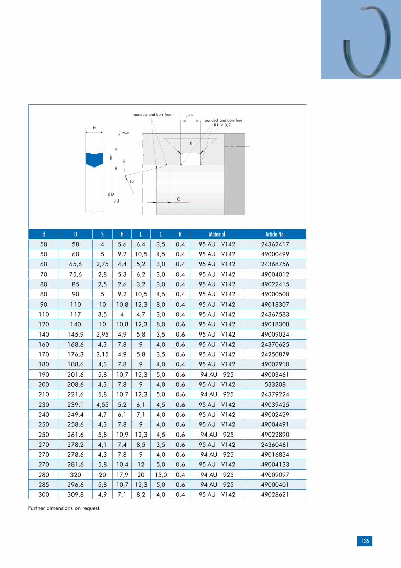
135
d D S H L C R Material Article No.
50 58 4 5,6 6,4 3,5 0,4 95 AU V142 24362417
50 60 5 9,2 10,5 4,5 0,4 95 AU V142 49000499
60 65,6 2,75 4,4 5,2 3,0 0,4 95 AU V142 24368756
70 75,6 2,8 5,3 6,2 3,0 0,4 95 AU V142 49004012
80 85 2,5 2,6 3,2 3,0 0,4 95 AU V142 49022415
80 90 5 9,2 10,5 4,5 0,4 95 AU V142 49000500
90 110 10 10,8 12,3 8,0 0,4 95 AU V142 49018307
110 117 3,5 4 4,7 3,0 0,4 95 AU V142 24367583
120 140 10 10,8 12,3 8,0 0,6 95 AU V142 49018308
140 145,9 2,95 4,9 5,8 3,5 0,6 95 AU V142 49009024
160 168,6 4,3 7,8 9 4,0 0,6 95 AU V142 24370625
170 176,3 3,15 4,9 5,8 3,5 0,6 95 AU V142 24250879
180 188,6 4,3 7,8 9 4,0 0,4 95 AU V142 49002910
190 201,6 5,8 10,7 12,3 5,0 0,6 94 AU 925 49003461
200 208,6 4,3 7,8 9 4,0 0,6 95 AU V142 533208
210 221,6 5,8 10,7 12,3 5,0 0,6 94 AU 925 24379224
230 239,1 4,55 5,2 6,1 4,5 0,6 95 AU V142 49039425
240 249,4 4,7 6,1 7,1 4,0 0,6 95 AU V142 49002429
250 258,6 4,3 7,8 9 4,0 0,6 95 AU V142 49004491
250 261,6 5,8 10,9 12,3 4,5 0,6 94 AU 925 49022890
270 278,2 4,1 7,4 8,5 3,5 0,6 95 AU V142 24360461
270 278,6 4,3 7,8 9 4,0 0,6 94 AU 925 49016834
270 281,6 5,8 10,4 12 5,0 0,6 95 AU V142 49004133
280 320 20 17,9 20 15,0 0,4 94 AU 925 49009097
285 296,6 5,8 10,7 12,3 5,0 0,6 94 AU 925 49000401
300 309,8 4,9 7,1 8,2 4,0 0,4 95 AU V142 49028621
Further dimensions on request.
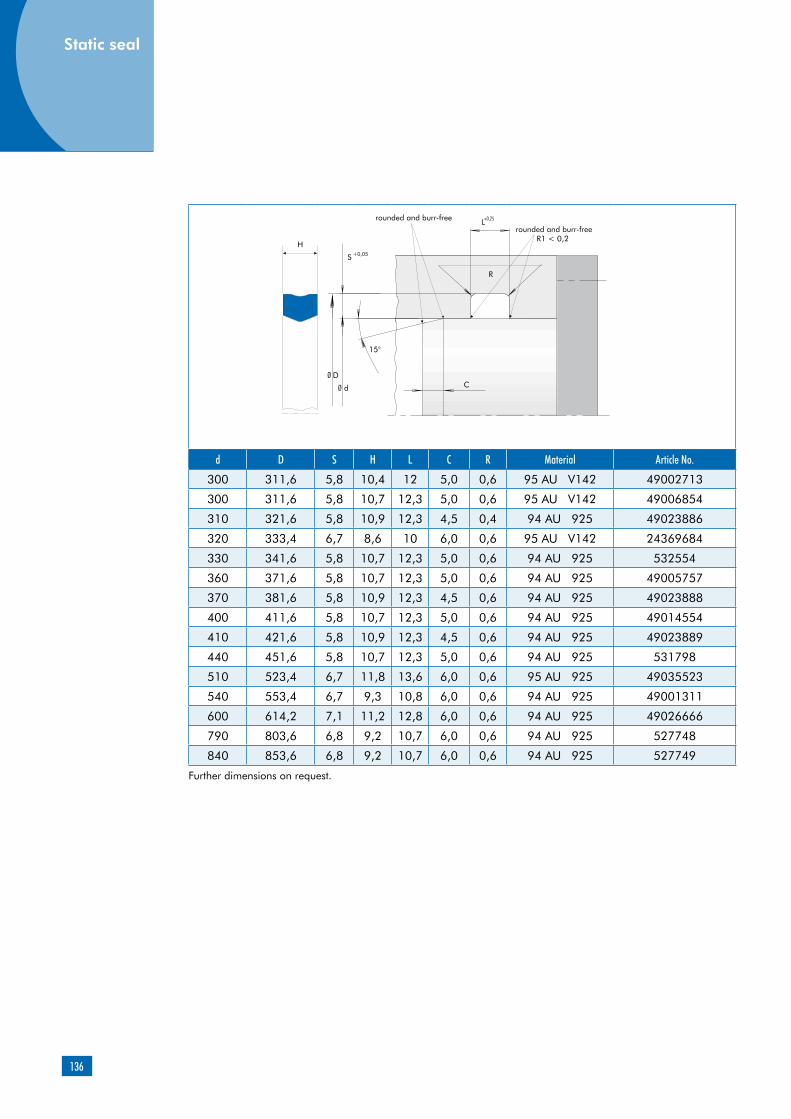
136
Static seal
d D S H L C R Material Article No.
300 311,6 5,8 10,4 12 5,0 0,6 95 AU V142 49002713
300 311,6 5,8 10,7 12,3 5,0 0,6 95 AU V142 49006854
310 321,6 5,8 10,9 12,3 4,5 0,4 94 AU 925 49023886
320 333,4 6,7 8,6 10 6,0 0,6 95 AU V142 24369684
330 341,6 5,8 10,7 12,3 5,0 0,6 94 AU 925 532554
360 371,6 5,8 10,7 12,3 5,0 0,6 94 AU 925 49005757
370 381,6 5,8 10,9 12,3 4,5 0,6 94 AU 925 49023888
400 411,6 5,8 10,7 12,3 5,0 0,6 94 AU 925 49014554
410 421,6 5,8 10,9 12,3 4,5 0,6 94 AU 925 49023889
440 451,6 5,8 10,7 12,3 5,0 0,6 94 AU 925 531798
510 523,4 6,7 11,8 13,6 6,0 0,6 95 AU 925 49035523
540 553,4 6,7 9,3 10,8 6,0 0,6 94 AU 925 49001311
600 614,2 7,1 11,2 12,8 6,0 0,6 94 AU 925 49026666
790 803,6 6,8 9,2 10,7 6,0 0,6 94 AU 925 527748
840 853,6 6,8 9,2 10,7 6,0 0,6 94 AU 925 527749
Further dimensions on request.

137
Product description
Product advantages
interchangeable with housings for O-ring and O-ring with back-up ringhigh degree of functional reliability pro-vided by the sturdy profile ring made of polyurethanegreat resistance to extrusion (dimensional stability)simple and safe assembly (single-piece element)simplified inventorygastight
Material Designation ColorPolyurethane 95 AU V142 dark-blue
Polyurethane 94 AU 925 light-blue
Applications
Single-piece, double-acting compact seal made of polyurethane for static sealing, external sealing.
Merkel Cover Seal PU 83
Material
High operating pressure (up to 60 MPa)
Breathing gap (cylinder expansion)
Short pressure build-up time (end-of-travel damping)
Reciprocal operating pressure
Nominal diameter up to 2,000mm
Polyurethane profile ring
Field of application
Material 95 AU V142/94 AU 925Hydraulic oils, HL, HLP -30 ... +110 °C
HFA fluids +5 ... +50 °C
HFB fluids +5 ... +50 °C
HFC fluids -30 ... +40 °C
HFD fluids -
Water +5 ... +40 °C
HETG (rape-seed oil) –30 … +60 °C
HEES (synth. ester) –30 … +60 °C
HEPG (glycol) –30 … +40 °C
Mineral greases –30 … +110 °C
Pressure 60 MPa
The figures given are maximum values and must not be applied simultaneously.
Peak-to-valley heights Ra Rmax
Sliding surface <0,8 µm <3,2 µm
Groove base <1,6 µm <6,3 µm
Groove sides <6,3 µm <20 µm
Surface finish
* burr-free transition
The material is determined on the basis of the nominal diameter and the manufacturing process.

138
Static seal
Installation & assembly
Please note our general remarks on design in the Merkel Technical Manual.
Section* Max. perm. gap dimension
16 MPa 26 MPa 32 MPa 40 MPa 60 MPa
1,78 0,2 0,2 0,15 0,1 0,1
2,62 0,35 0,3 0,25 0,15 0,1
3,5/3,53 0,5 0,4 0,35 0,25 0,2
5,33 0,5 0,4 0,35 0,25 0,2
6,99/7,0 0,55 0,45 0,35 0,35 0,25
8,0 0,55 0,45 0,4 0,35 0,25
8,4 0,55 0,45 0,4 0,35 0,25
10,0 0,6 0,5 0,45 0,4 0,3
12,0 0,6 0,5 0,45 0,4 0,3
Gap dimensionThe maximum permissible extrusion gap for a piston rod arranged on one side, while taking tube expansion into account, is determined, to a large extent, by the maximum operating pressure and the dimensional stability of the sealing material, depending on the temperature involved.
* Cord thickness for housing recommendation O-ring with a back-up ring
Tolerances
Diameter D Tolerance
< 800 H7/f7
> 800 +0,1 / -0,05 / -0,15
Operating principle
Design notes
Please note our general remarks on the installation of hydraulic seals in the Merkel Technical Manual.
Cover Seal PU 83 at an operating pressure of 40 MPa
O-ring with a PTFE back-up ring at an operating pressure of 40 MPa
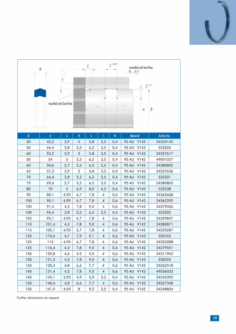
139
D d S H L C R Material Article No.
50 42,2 3,9 5 5,8 3,5 0,4 95 AU V142 24334142
50 44,4 2,8 5,3 6,2 3,5 0,4 95 AU V142 532203
60 52,2 3,9 5 5,8 3,5 0,4 95 AU V142 24327617
60 54 3 5,3 6,2 3,5 0,4 95 AU V142 49001027
60 54,6 2,7 5,5 6,5 3,5 0,4 95 AU V142 24380802
65 57,2 3,9 5 5,8 3,5 0,4 95 AU V142 24327636
70 64,4 2,8 5,2 6,2 3,5 0,4 95 AU V142 532201
75 69,6 2,7 5,5 6,5 3,5 0,4 95 AU V142 24380803
80 70 5 6,9 8,0 4,5 0,6 95 AU V142 532538
90 80,1 4,95 6,7 7,8 4 0,6 95 AU V142 24362668
100 90,1 4,95 6,7 7,8 4 0,6 95 AU V142 24362292
100 91,4 4,3 7,8 9,0 4 0,6 95 AU V142 24379356
100 94,4 2,8 5,2 6,2 3,5 0,4 95 AU V142 532202
105 95,1 4,95 6,7 7,8 4 0,6 95 AU V142 24359847
110 101,4 4,3 7,8 9,0 4 0,6 95 AU V142 24380871
115 105,1 4,95 6,7 7,8 4 0,6 95 AU V142 24355287
120 110,6 4,7 7,9 9,1 4 0,6 95 AU V142 530765
125 115 4,95 6,7 7,8 4 0,6 95 AU V142 24355288
125 116,4 4,3 7,8 9,0 4 0,6 95 AU V142 24379551
130 120,8 4,6 4,2 5,0 4 0,6 95 AU V142 24311962
130 121,4 4,3 7,8 9,0 4 0,6 95 AU V142 528353
140 130,4 4,8 6,6 7,7 4 0,6 95 AU V142 24362518
140 131,4 4,3 7,8 9,0 4 0,6 95 AU V142 49036033
140 134,1 2,95 4,9 5,9 3,5 0,4 95 AU V142 24245392
150 140,4 4,8 6,6 7,7 4 0,6 95 AU V142 24367348
150 141,9 4,05 8 9,2 3,5 0,4 95 AU V142 24348854
Further dimensions on request.

140
Static seal
D d S H L C R Material Article No.
160 151,4 4,3 7,8 9,0 4 0,6 95 AU V142 49036034
180 170 5 7,3 8,4 4,5 0,6 95 AU V142 24378895
180 174,4 2,8 5,2 6,2 3,5 0,4 95 AU V142 49001429
190 170 10 7,8 9,0 8 0,6 95 AU V142 24361640
200 191,4 4,3 7,8 9,0 4 0,6 95 AU V142 49004492
210 201,4 4,3 7,8 9,0 4 0,6 94 AU 925 49035972
225 216,4 4,3 7,8 9,0 4 0,6 95 AU V142 531563
240 228,4 5,8 10,7 12,3 5 0,6 95 AU V142 24375294
240 231,4 4,3 7,8 9,0 4 0,6 95 AU V142 24360083
250 241,4 4,3 7,8 9,0 4 0,6 95 AU V142 49022154
270 261,4 4,3 7,7 9,0 4 0,6 94 AU 925 49017087
280 268,4 5,8 10,9 12,3 5 0,6 95 AU V142 49033375
290 281,4 4,3 8,1 8,8 4 0,6 95 AU V142 525514
300 290,4 4,8 8,1 9,3 4 0,6 95 AU V142 49016225
310 298,4 5,8 10,7 12,3 5 0,6 94 AU 925 49038888
320 308,4 5,8 10,4 12,0 5,5 0,6 95 AU V142 529772
330 318,4 5,8 10,9 12,3 5 0,6 95 AU V142 49027154
340 331,4 4,3 7,7 9,0 4 0,6 95 AU V142 525487
350 338,4 5,8 10,7 12,3 5 0,6 94 AU 925 49038889
360 348,4 5,8 10,4 12,0 5,5 0,6 94 AU 925 49004019
380 368,4 5,8 10,9 12,3 5 0,6 95 AU V142 49033376
390 378,4 5,8 10,4 12,0 5,5 0,6 95 AU V142 49002712
400 388,4 5,8 10,7 12,3 5 0,6 95 AU V142 532306
410 398,4 5,8 10,7 12,3 5 0,6 95 AU V142 49001342
420 408,4 5,8 10,7 12,3 5 0,6 95 AU V142 24379139
430 418,4 5,8 10,9 12,3 5 0,6 95 AU V142 49027155
Further dimensions on request.

141
D d S H L C R Material Article No.
440 428,4 5,8 10,9 12,3 5 0,6 94 AU 925 49030619
450 438,4 5,8 10,7 12,3 5 0,6 95 AU V142 529212
460 448,4 5,8 10,9 12,3 5 0,6 94 AU 925 49023288
470 458,4 5,8 10,7 12,3 5 0,6 94 AU 925 49021561
480 468,4 5,8 10,9 12,3 5 0,6 94 AU 925 49025771
490 478,4 5,8 10,9 12,3 5 0,6 95 AU V142 49033377
500 488,4 5,8 10,7 12,3 5 0,6 95 AU V142 530849
520 508,4 5,8 10,6 12,3 5,5 0,6 95 AU V142 532963
530 518,4 5,8 10,6 12,3 5,5 0,6 95 AU V142 529838
550 536,6 6,7 11,8 13,6 6 0,6 94 AU 925 49000360
560 548,4 5,8 10,9 12,3 5,5 0,6 94 AU 925 49027156
570 556,6 6,7 11,8 13,6 6 0,6 94 AU 925 49007603
580 566,6 6,7 11,8 13,6 6 0,6 94 AU 925 531187
600 586,6 6,7 11,8 13,6 6 0,6 93 AU V168 49001757
680 668,4 5,8 10,6 12,3 4,5 0,6 94 AU 925 49038887
690 673 8,5 14,4 16,3 7 0,6 94 AU 925 49026186
700 683 8,5 14,4 16,3 7 0,6 94 AU 925 49035978
740 723 8,5 14,4 16,3 7 0,6 94 AU 925 49026187
810 793 8,5 14,4 16,3 7 0,6 94 AU 925 49015798
830 813 8,5 15,6 16,3 7 0,6 94 AU 925 24361263
860 843 8,5 14,4 16,3 7 0,6 94 AU 925 49015799
960 943 8,5 14,4 16,3 7 0,6 94 AU 925 49012180
Further dimensions on request.

142
Static seal
Merkel Stircomatic SRC
Product description
Product advantages
interchangeable with housings for O-ring and O-ring with back-up ringfirm seat inside the housing provided by opti-mally designed sealing edges (stress distribu-tion)high degree of functional reliability provided by the sturdy profile ring made of polyurethanefunctional reliability resulting from a great resi-stance to extrusion (dimensional stability)simple and safe assemblygastight
Material Designation ColorPolyurethane 95 AU V142 dark-blue
Polyurethane 94 AU 925 light-blue
Applications
Single-piece compact seal made of poly-urethane for static sealing, axially sealing component.
Material
Polyurethane profile ring
Material 95 AU V142/94 AU 925
Hydraulic oils, HL, HLP -30 ... +110 °C
HFA fluids +5 ... +50 °C
HFB fluids +5 ... +50 °C
HFC fluids -30 ... +40 °C
HFD fluids -
Water +5 ... +40 °C
HETG (rape-seed oil) –30 … +60 °C
HEES (synth. ester) –30 … +60 °C
HEPG (glycol) –30 … +40 °C
Mineral greases –30 … +110 °C
Pressure 80 MPa
The figures given are maximum values and must not be applied simultaneously.
Peak-to-valley heights Ra Rmax
Sealing surfaces <1,6 µm <6,3 µm
Groove sides <6,3 µm <20 µm
Surface finish
The material is determined on the basis of the nominal diameter and the manufacturing process.
Field of application
More accurate values for Ra and Rmax should be set within the sealing surfaces for applications requiring gastight operation.
Tolerances
Diameter Tolerance
d h10
D H9
Negative pressure (flowing medium)
Pulsating pressure
High operating pressure (up to 80 MPa)
Nominal diameter up to 2,000mm
The housing for the Stircomatic SRC may be de-signed with an aperture in inner diameter direc-tion or in the form of an axial recess. Pressure is applied from the interior. Please note our general remarks on design in the Merkel Technical Manual.
Installation & assembly
Design notes
Please note our general remarks on the instal-lation of hydraulic seals in the Merkel Technical Manual.

143
d D H L Profile Material Article No.
40,0 48,0 3,00 2,4 4,0 95 AU V142 24343125
45,0 53,0 3,00 2,4 4,0 95 AU V142 49003451
50,0 58,0 3,10 2,5 4,0 95 AU V142 24350857
60,0 68,0 3,10 2,5 4,0 95 AU V142 24367175
60,0 70,0 5,00 4,0 5,0 95 AU V142 24374887
75,0 83,0 3,10 2,5 4,0 95 AU V142 24367176
90,0 100,0 3,80 3,0 5,0 95 AU V142 532063
102,0 110,0 3,10 2,5 4,0 95 AU V142 49031644
122,0 130,0 3,10 2,5 4,0 95 AU V142 49031645
132,0 140,0 3,10 2,5 4,0 95 AU V142 49031646
235,4 260,0 7,25 5,8 12,3 95 AU V142 49043603
295,4 320,0 7,25 5,8 12,3 95 AU V142 49017430
335,4 360,0 7,25 5,8 12,3 95 AU 925 49017431
349,4 370,0 7,25 5,8 10,3 94 AU 925 49031386
415,4 440,0 7,25 5,8 12,3 95 AU V142 49017432
460,4 485,0 7,25 5,8 12,3 95 AU V142 49016295
469,4 490,0 7,25 5,8 10,3 94 AU 925 49045102
512,8 540,0 8,35 6,7 13,6 94 AU 925 49017433
542,8 570,0 8,35 6,7 13,6 94 AU 925 49026033
587,8 615,0 8,35 6,7 13,6 94 AU 925 49017434
725,0 750,0 8,95 7,2 12,5 94 AU 925 49017436
795,0 820,0 8,95 7,2 12,5 94 AU 925 49032358
815,0 840,0 8,95 7,2 12,5 94 AU 925 49028615
995,0 1.020,0 8,95 7,2 12,5 94 AU 925 49031377
1.015,0 1.040,0 8,95 7,2 12,5 94 AU 925 49017437
1.065,0 1.090,0 8,95 7,2 12,5 94 AU 925 49045105
Further dimensions on request.
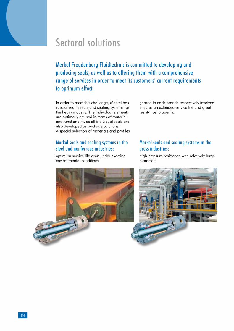
144
Sectoral solutions
In order to meet this challenge, Merkel has specialized in seals and sealing systems for the heavy industry. The individual elements are optimally attuned in terms of material and functionality, as all individual seals are also developed as package solutions. A special selection of materials and profiles
geared to each branch respectively involved ensures an extended service life and great resistance to agents.
Merkel Freudenberg Fluidtechnic is committed to developing and producing seals, as well as to offering them with a comprehensive range of services in order to meet its customers’ current requirements to optimum effect.
Merkel seals and sealing systems in the steel and nonferrous industries:optimum service life even under exacting environmental conditions
Merkel seals and sealing systems in the press industries:high pressure resistance with relatively large diameters
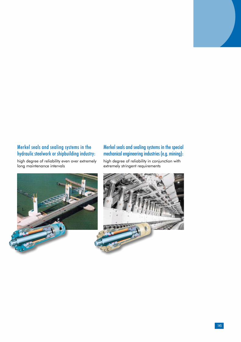
145
Merkel seals and sealing systems in the hydraulic steelwork or shipbuilding industry:high degree of reliability even over extremely long maintenance intervals
Merkel seals and sealing systems in the special mechanical engineering industries (e.g. mining):high degree of reliability in conjunction with extremely stringent requirements
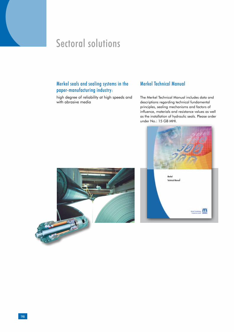
146
Merkel seals and sealing systems in the paper-manufacturing industry:high degree of reliability at high speeds and with abrasive media
Merkel Technical Manual
The Merkel Technical Manual includes data and descriptions regarding technical fundamental principles, sealing mechanisms and factors of influence, materials and resistance values as well as the installation of hydraulic seals. Please order under No.: 15 GB MHI.
Sectoral solutions
Merkel
Technical Manual

147
The figures indicated in the catalog are based on experiences gathered within the Freudenberg Group in the field of research over several decades for the development and manufacture of seals and they are in line with today’s state-of-the-art expertise. However, the sealing effect provided by numerous products mentioned in the cata-log is not only generated by the component proper. It is rather based to a very large extent – depending on the specific application involved – on other parameters such as the place of installation and counter rotation, the pressure applied, the operating temperature, the media to be sealed, the lubrication, vibra-tion-related influences and possible dirt from outside. These and further unknown factors
are likely to exert a tangible influence on the function of seals in practical applications. Against this background, no standard state-ments can be made about the function of the products mentioned in the catalog. The data stated in the latter merely represent general, non-binding reference values which cannot be applied to every case of application. As a result, we recommend that you discuss con-crete cases of application with our consulting services.In the event of higher and special stresses, e.g. exerted by aggressive media, the seal should be selected in cooperation with us, as functional reliability tests are frequently indispensable.

148
Asia Merkel Freudenberg Fluidtechnic GmbHc/o EKK Eagle Industry Asia Pacific Pte. Ltd.52 Serangoon North Avenue 4# 03-02, Ever Tech BuildingSingapore 555853E-Mail: [email protected]
America Freudenberg-NOKMerkel Heavy Industry11617 State Route 13Milan, OH 44846/USAE-Mail: [email protected]
Headquarter Europa Merkel Freudenberg Fluidtechnic GmbHIndustriestraße 64 D-21107 HamburgE-Mail: [email protected]
www.merkel-heavy-industry.com
Take advantage of our excellent services worldwide:
120,000 widely diversified products
Very high degree of availability,
prompt worldwide supplies
Built-to-order; rapid, tailor-made,
economical
Optimum solutions for challenging
special applications
Individual test series under genuine
conditions
Immediate assistance in the event of
repairs
Boost your success with our sealing expertise:
Perfect sealing technology for top
productivity
Leading material know-how
Extrusion-proof products with a long
service life and extended service
intervals
Absolute functional reliability of the
seals under the most diversified and
extremely stringent conditions
Experience gathered in sealing
technology since 1899
Merkel - by your side around the globe
Merkel ServiceMerkel Quality & Value
MerkelHeavy Industry 18
GB
MHI 1
.0 12
08
Phone.: +49 (0)40/75306-0
www.merkel-heavy-industry.com
Please contact our product management for injection molding technology:
A member of the Freudenberg Group.