michael bahrman, p.e. ieee psce atlanta, november 1, … · $7.69 $10.97 $8.62 $9.37 $16.82 $13.97...
TRANSCRIPT
HVDC Transmission
Image Image
Michael Bahrman, P.E.IEEE PSCE
Atlanta, November 1, 2006

©H
VDC
Tra
nsm
issi
on -
Page
2
ApplicationsLong-distance, bulk-power OVHD transmissionSea and land cable transmissionAsynchronous interconnectionsPower flow controlCongestion relief
RatingsPower range up to 4000 MW at ± 500 kVPower range up to 4800 MW at ± 600 kVVoltage range increasing to ± 800 kV for 2009 operationPower range up to 6400 MW at ± 800 kVMIND Cables
HVDC Transmission

©H
VDC
Tra
nsm
issi
on -
Page
3
Long-Distance Bulk Power Transmission
3 x 800 kV AC6300 MW
2 x ± 600 kV DC6300 MW
ITAIPU2 x 6300 MW
345 kV AC400 MW
± 500 kV DC3000 MW
Generator Outlet TransmissionMore power on fewer linesImproved stabilityLower installed costReduced lossesDouble circuit (bipolar line)Reduced ROWOne line vs. two – e.g. IPP, CU, Square Butte
InterconnectionsFirm capacityBypass congestionAvoid loop flowNo limit due to parallel pathsInterconnect diverse regions

©H
VDC
Tra
nsm
issi
on -
Page
4
Cost Comparison of 3000 MW Transmission Systems
± 500 kV 2 x ± 500 kV ± 600 kV ± 800 kV 500 kV 500 kV 765 kV ± 500 kV 500 kV Total Bipole 2 Bipoles Bipole Bipole 2 Single Ckt Double Ckt 2 Single Ckt Bipole Single Ckt AC+DC
3000 4000 3000 3000 3000 3000 3000 3000 1500 4500$420 $680 $465 $510 $542 $542 $630 $420 $302 $722
$1.60 $1.60 $1.80 $1.95 $2.00 $3.20 $2.80 $1.60 $2.00750 1,500 750 750 1,500 750 1,500 750 750 1,500
$1,200 $2,400 $1,350 $1,463 $3,000 $2,400 $4,200 $1,200 $1,500 $2,700$1,620 $3,080 $1,815 $1,973 $3,542 $2,942 $4,830 $1,620 $1,802 $3,422
$172 $327 $193 $209 $376 $312 $512 $172 $191 $363$57.28 $81.68 $64.18 $69.75 $125.24 $104.03 $170.77 $57.28 $127.40 $80.66
$7.69 $10.97 $8.62 $9.37 $16.82 $13.97 $22.93 $7.69 $17.11 $10.83
Losses @ full load 193 134 148 103 208 208 139 106 48 154Losses at full load in % 6.44% 3.35% 4.93% 3.43% 6.93% 6.93% 4.62% 5.29% 4.79% 5.12%Capitalized cost of losses @ $1500 kW (M$) $246 $171 $188 $131 $265 $265 $177 $135 $61 $196
10%$1,500
Note:AC current assumes 94% pfFull load converter station losses = 0.75% per stationTotal substation losses (transformers, reactors) assumed = 0.5% of rated power
Distance in miles
Cost per MWh @ 85% Utilization Factor
DC Alternatives
Parameters:
Alternative
Interest rate %Capitalized cost of losses $/kW
Cost per kW-Yr
Station costs including reactive compenstation Transmission line cost (M$/mile)
Rated Power (MW)
Annual Payment, 30 years @10%
Transmission Line Cost (M$)Total Cost (M$)
Hybrid AC/DC AlternativeAC Alternatives
Capital Cost

©H
VDC
Tra
nsm
issi
on -
Page
5
Comparison to Rail Transport of Coal
3000 MW power plantCoal haul distance 900 milesFuel – sub-bituminous coal 8500 BTU/lb Plant heat rate – 8500 BTU/kWh, 85% load factor3 unit trains per day (100, 100 ton cars/train)Annual hauling cost $560 M at $50 per ton
$186 per kW-yr$25 per MWh20 million gallons of diesel fuel per year @ 500 net ton miles per gallon
Subject to escalation, congestionCannot deliver energy from renewable resources

©H
VDC
Tra
nsm
issi
on -
Page
6
The HVDC Classic Converter Station
Converter station Transmissionline or cable
Converter
Smoothingreactor
DC filter
Telecommunication
Controlsystem
AC filtersShunt
capacitorsor otherreactive
equipment
AC bus
~~

©H
VDC
Tra
nsm
issi
on -
Page
7
The HVDC Classic Converter Station
AC DC
HVDCHVDC--CSCCSC
Indoor
Outdoor
AC FiltersAC Filters
DC FiltersDC Filters
Thyristor ValvesThyristor Valves
Converter Converter TransformersTransformers

©H
VDC
Tra
nsm
issi
on -
Page
8
Shunt CapacitorBanks
AC FilterBanks
Converter Building
AC Switchyard
DC Switchyard
HVDC Converter Station Design

©H
VDC
Tra
nsm
issi
on -
Page
9
HVDC Operating Configurations and Modes

©H
VDC
Tra
nsm
issi
on -
Page
10
uR
uS
uT
1 3 5
4 6 2
Id
Ud
IR
IS
IT
IR
IS
αu
IT
HVDC Classic Control

©H
VDC
Tra
nsm
issi
on -
Page
11
Asynchronous Interconnections
Asynchonous borders
EconomicFirm transactionsShared reservesIncrease diversityEconomy energy trade
ReliabilityEmergency power supportMutual assistanceIsolate disturbances‘Fire-wall’ against cascading outagesReserve sharing
HVDC in North America

©H
VDC
Tra
nsm
issi
on -
Page
12
The CCC* Converter Station*Capacitively-commutated converter station
TransmissionLine, Cable or Back-Back
Converter
Controlsystem
Contune AC filters
AC bus
Smoothingreactor
DC filter
Telecommunication~~
Commutation capacitors
Weaker Systems
Back-to-Back
100 - 550 MW

©H
VDC
Tra
nsm
issi
on -
Page
13
Modular Back-toBack CCC Asynchronous Tie

©H
VDC
Tra
nsm
issi
on -
Page
14
ApplicationsUnderground and sea cable transmissionOff-shore - platforms, islandsUrban in-feedConstrained ROWVirtual generator for replacement of RMR generationIntegration of remote renewable generationImproved voltage stability
RatingsPower range 50-1100 MWVoltages ± 80, ± 150 and ± 300 kVExtruded cables with prefabricated joints
HVDC Light Transmission – Voltage Source Converters

©H
VDC
Tra
nsm
issi
on -
Page
15 0
200400600800
100012001400160018002000
1970
1973
1976
1979
1982
1985
1990
1993
1996
1999
2002
2005
2008
2011
Thyristor MW Thyristor kV IGBT MW IGBT kV
HVDC Solid State Converter Development

©H
VDC
Tra
nsm
issi
on -
Page
16
HVDC Light Station
Converter station
Transmission Cable
Voltage Source(d) Converter - VSC
AC filters
AC bus
Controlsystem
PhaseReactor
DC Capacitor
IGBT Valves
Dry DC Capacitor
Strong or Weak SystemsDynamic Voltage ControlUnderground TransmissionUp to ±150kV, 550MWUp to ±300kV, 1100MW

©H
VDC
Tra
nsm
issi
on -
Page
17
SingleValve
DoubleValve
QuadrupleValve
Thyristor Module
Thyristors
IGBT Valve Stacks
StakPak
Submodule
Chip
Cable Pair
HVDC Converter Arrangements
Conventional HVDC
VSC Based HVDC

©H
VDC
Tra
nsm
issi
on -
Page
18
Underground Cable Systems with HVDC LightEconomic
No distance limitationFull utilization – no reactive powerTwo cables v three cables for ACLight, flexible and simpler designTimely permittingNo induced circulating currentsHalf the lossesEasier transport and installation
ReliabilityNo cable overloads possibleDynamic reactive power supportCongestion reliefIsolate disturbancesShare ROW without increasing exposureBlack-start capability
Land
Sea

©H
VDC
Tra
nsm
issi
on -
Page
19
HVDC Light Converter Station
AC DC
HVDCHVDC--VSCVSC
Indoor
Outdoor
IGBT ValvesIGBT Valves

©H
VDC
Tra
nsm
issi
on -
Page
20 AC Harmonic Filters
DC Capacitors(Voltage Sources)
Converter Valves
Phase Reactors
Cables
AC Transformers, breakers/disconnects
Simplified Single Line Diagram (SLD)
HVDC Transmission with Voltage Source Converters
©H
VDC
Tra
nsm
issi
on -
Page
21
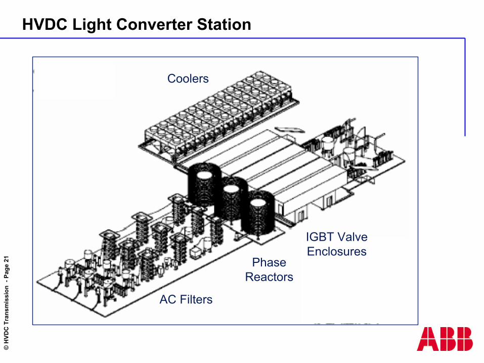
AC Filters
Phase Reactors
IGBT Valve Enclosures
Coolers
HVDC Light Converter Station

©H
VDC
Tra
nsm
issi
on -
Page
22
Principle control of HVDC-Light
DCvoltagecontrol
uDC-ref1
uDC1
+
-
uAC1uAC-ref1
pref1
DCvoltagecontrol
uDC-ref2
uDC2
+
-
uAC2 uAC-ref2
pref2 q ref2
ACvoltagecontrol
PWMinternalcurrentcontrol
PWMinternalcurrentcontrol
qref1
ACvoltagecontrol
+
-i i
K
K
K
K
AC Line Voltages OPWM
Control of VSC Based HVDC Transmission

©H
VDC
Tra
nsm
issi
on -
Page
23
Troll A 2 x 40 MW HVDC
Offshore Applications of HVDC Light

©H
VDC
Tra
nsm
issi
on -
Page
24
Reactive Power (p.u.)
Act
ive
Pow
er (p
.u.)
Operating Area
P-Q Diagram
HVDC VSC Operating Range
Comparison of Reactive Power Characteristics