micro-cathode arc thruster development and...
TRANSCRIPT

Micro-Cathode Arc Thruster Development and
Characterization
IEPC-2011-266
Presented at the 32nd International Electric Propulsion Conference,Wiesbaden, GermanySeptember 11–15, 2011
Taisen Zhuang, Alexey Shashurin, Dereck Chiu, George Teel and Michael Keidar.
The George Washington University, Department of Mechanical and Aerospace Engineering Washington, DC 20052
The performance of the micro-cathode arc thruster (µCAT) and coaxial micro-cathodearc thruster (CA-µCAT) have been investigated. In particular, mass consumption rateof these thruster variants was measured. Using the mass consumption rate, the specificimpulse of the µCAT was calculated from the thrust data and compared to the ion velocitymeasurements. This comparison suggests that plasma plume is highly ionized. Moreover,two thruster performance have been compared. The potential application for both thrusterhave been discussed in the paper.
Introduction
Micro-cathode arc thruster (µCAT) is a micro-Newton level vacuum arc propulsion system has beeninvestigated and studied, which has been known as its compatible for nano-satellite applications due to itslow operating voltage, low mass, and its simplicity to be integrated into the spacecraft operating system1,.2
In general, the µCAT vacuum arc is established by using tubular ring geometry with a same inner diam-eter anode and cathode separated by insulator3,4,5,6 . With adding directional magnetic field on µCAT,an expected cathode spot motation in the azimuthal direction has been found4,5 which is critical for cath-ode metal uniform erosion of cathode material.4 Moreover, the drift speed of 40000 50000 ms−1 at 0.3 Tmagnetic field was measured and dependences of thrust and total ion output on the magnetic field strength4,.5
The magnetic field dependent is that the cathodic plasma expands away from the cathode in a directionnormal to the surface; the plasma will be trapped inside of the thruster channel. The magnetic field couldincrease of thruster output and thrust due to the plasma flow transformation into the axial flow. While ithas to be point that the thrust increase not only depend on the total output, also caused by increase ofion velocity by magnetic field. However, apart from the transportation effect caused by magnetic field, aapproach have been tried to increase the total ion output and thrust without being limited by geometry.
A new coaxial thruster geometry with a relatively small diameter anode which is surrounded by an in-sulator and a cathode was designed namely coaxial micro-cathode arc thruster (CA-µCAT). The plasmaspark was generated in the edge of the cathode and insulator surface, without being blocked by the channelof thruster itself. In this paper, performance of µCAT and CA-µCAT were characterized. Measurement ofcathode mass consumption rate was measured as function of magnetic field for both µCAT and CA-µCATand performance characteristics of these thruster variant were compared.
I. Experimental Details
A. Thruster Design
The schematics of the µCAT and CA-µCAT is shown in Figure 1. The Figure1 (a) shows the schematicsof µCAT equipped with tubular titanium electrodes aligned in axial direction. Electrodes are separated by1mm thickness ceramic ring. Figure 1 (b) shows the schematics of the CA-µCAT in which the tubular tita-
1The 32nd International Electric Propulsion Conference, Wiesbaden, Germany
September 11–15, 2011

nium electrodes are place in concentric annulus direction separated by a 1.5 mm thickness insulating tube.For both design, the insulators surface were coated with carbon paint with resistance on the order of 1-10KΩ in order to initiate the arc. Following pulsed are based on triggerless concept due to thing film depositionduring the arcing as described in7,8 Furthermore, the cathode tube (titanium electrode) is pushed by springwhich works as two mainly functions. First, it is design for a simple and a robust feed mechanism whichspring will push the cathode tube forward when the discharge etched the cathode tube material. Second,spring is connected to the power process unit to apply negative potential to the cathode electrode.
As shown in Figure 1, magnetic field coil and magnetic core are mounted outside of the electrodes toprovide specify distribution magnetic field. The coil is designed to use 0.5 mm diameter copper wire windedup to 700 turns. It is co-axial with the electrode axis and a magnetic core (steel 1020) has the shape of awasher with a thickness of about 2 mm in attempt to generate special distribution magnetic field. In theprevious works in3,4 it has been notice that magnetic field plays a critical role for efficiency of plasma plumetransportation process of in µCAT. More experiment details will be discussed about the magnetic field effecton CA-µCAT in the following chapter.
Cathode AnodeIsolator
Z0
Magnetic Coil and Core
Magnetic Core Magnetic CoilInsulated Shell
Spring CathodeAnode Insulator
Figure 1. Schematic of micro-cathode arc thruster (a) and concentric co-axial micro-cathode arc thruster (b).
B. Power Supply
An inductive energy stores system has been designed to as power process unit (PPU) for the - µCATand CA- µCAT. The Figure 2 shows the schematic of the PPU. When the PPU semiconductor is transistora triggered pulse of about LdI/dt will be apply between the electrodes. This leads to a breakdown and arcdischarge between the electrodes. More details about PPU please see Ref,3 Anders1998.
20-30 V Switch
Cathode Anode
Isolator
Inductor0.1 W
Iarc
U
2The 32nd International Electric Propulsion Conference, Wiesbaden, Germany
September 11–15, 2011

In order to produce a low mass system, the Power Process Unit was constructed using a embed micro-process unit as shown in the Figure 3, a programmable AT MEGA328 chip is used to generate drive pulsefor both thruster and magnetic field coil. The total size of driver system (without inductor) is 0.8×0.8×1.5inch as shown in the Figure 3 almost same size of quarter coin. In the PPU, the IGBT switch that couldsurvive with maximum current 120A and voltage 1200V was used. By varying the length of the triggersignal, the whole programable system could control the level of the current in the switch and thereby theenergy stored in the inductor can also be adjusted. Obviously, varying the input signal as well can changethe repetition rate of the individual pulse.
Figure 3. Power process unit with embed programable system. The dimension of system is 0.8×0.8×1.5 inch.
II. Thruster Performance
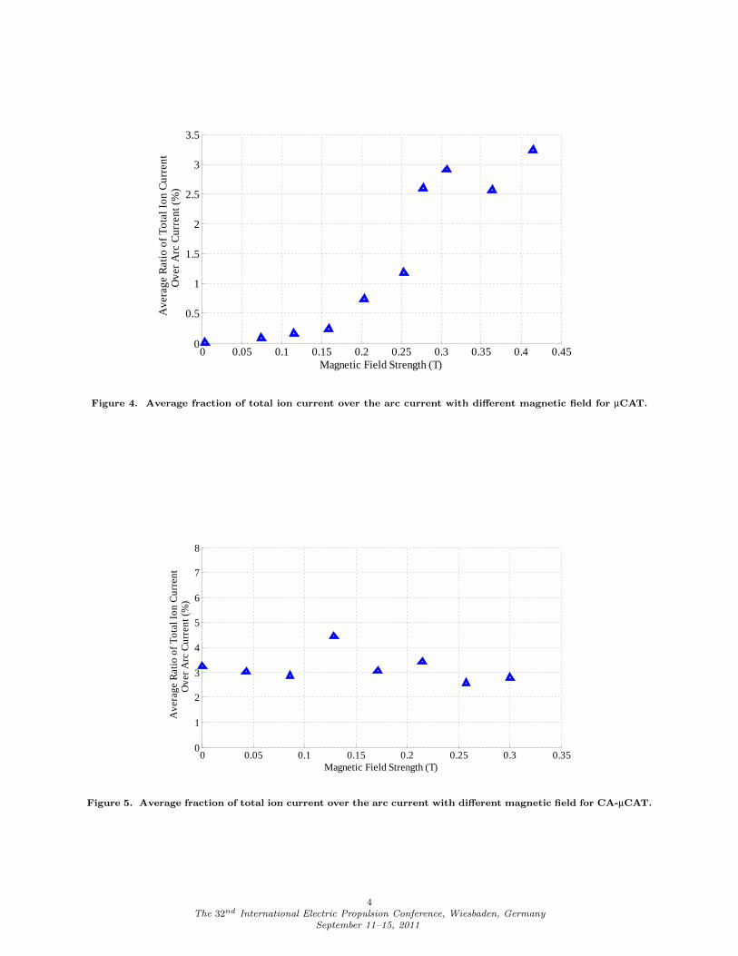
The new configuration of CA-µCAT design is based on the previously development of the µCAT. It isknown that the cathodic plasma expands away from cathode in a direction normal to the surface. In partic-ular case of the µCAT, (see Figure 1), the cathodic plasma expands away in a direction normal to the innersurface of the cathode tube. In order to change the plasma expands direction into axis direction, a magneticfield was applied to transport the plasma and increase the total output of the thruster. The Figure 4 showsthe average ratio of total ion current over the arc current. One can see that with increase of magnetic field,the ratio increase significantly to around 3.5% which corresponds to the efficiency of cathodic jet transportthrough the thruster channel of about 45%.5 On the other hand the new configuration of CA-µCAT isdesigned in a coaxial direction in which the plasma will expands in normal to the surface of the insulator.Comparing the geometry shown in Figure 1 of µCAT and CA-µCAT, one can notice that the new geometrywill not be limited by the plasma transportation effect of magnetic field. The Figure 5 shows the averageratio of total ion current over the arc current for CA-µCAT. In fact, one can find that the ratio of ion currentover the arc current keeps constant which around 3.5% which is the maximum ratio of µCAT with maximummagnetic field. The ratio of total ion current over the arc current does not depends on the magnetic fieldfor new configuration of thruster.
Ion velocity measurements (using the initial peak method as described in Ref5) as a function of a magneticfield were performed. It was found that the magnetic field leads a increase the ion drift velocity from 20km/s to about 50 km/s. The Figure 6 and Figure 7 show the average drift velocity of µCAT and CA-µCAT.It is clearly seen that the average ion velocity increased 3-4 times with the added magnetic field of 0.3 Twhen comparing to the 0T magnetic field. Moreover, the ion velocity is around 2×10⁴ m/s in the case of 0T magnetic field, which is typically velocity (cathode electrode material is Titanium) at 0 T magnetic fieldcoincides with the experiment data in Ref.9 Thus both thruster variants exhibit the dependence of the ionvelocity on the magnetic field.
Cathodic material consumption rate has been measured by a high accurate mass balance with the accu-racy of about 0.001mg. Thrusters were fired around 20000 pulsed at each magnetic field strength. The mass
3The 32nd International Electric Propulsion Conference, Wiesbaden, Germany
September 11–15, 2011
0 0.05 0.1 0.15 0.2 0.25 0.3 0.35 0.4 0.450
0.5
1
1.5
2
2.5
3
3.5
Magnetic Field Strength (T)
Ave
rage
Rat
io o
f T
otal
Ion
Cur
rent
Ove
r A
rc C
urre
nt (
%)
Figure 4. Average fraction of total ion current over the arc current with different magnetic field for µCAT.
0 0.05 0.1 0.15 0.2 0.25 0.3 0.350
1
2
3
4
5
6
7
8
Magnetic Field Strength (T)
Ave
rage
Rat
io o
f T
otal
Ion
Cur
rent
Ove
r A
rc C
urre
nt (
%)
Figure 5. Average fraction of total ion current over the arc current with different magnetic field for CA-µCAT.
4The 32nd International Electric Propulsion Conference, Wiesbaden, Germany
September 11–15, 2011

0 0.05 0.1 0.15 0.2 0.250
20
40
60
80
100
120
140
Magnetic Field Strength (T)
Ion
Vel
ocity
(K
m/s
)
Figure 6. µCAT average ion drift velocity with different magnetic field applied, which measured with fourgrids initial peak method.
0 0.05 0.1 0.15 0.2 0.25 0.30
20
40
60
80
100
120
140
Magnetic Field Strength (T)
Ion
Vel
ocity
(K
m/s
)
Figure 7. CA-µCAT average ion drift velocity with different magnetic field applied, which measured with fourgrids initial peak method.
5The 32nd International Electric Propulsion Conference, Wiesbaden, Germany
September 11–15, 2011

changes have been recorded to build a function between the average cathodic material consumption rate andmagnetic field strength. The arc current was recorded to compare the performance for two thrusters to beused to calculate the mass consumption per charged Coulomb. Generally, cathodic material consumptionrate in proportion to the arc current. The Figure 8 shows the thruster cathode material consumption rate,which plotted with different magnetic field strength.
0 0.05 0.1 0.15 0.2 0.25 0.30
1
2
3
4
5
6x 10
-4
Magnetic Field Strength (T)
Cat
hode
Mat
eria
l Con
sum
ptio
n pe
r P
ulse
(m
g)
µCAT Data
CA-µCAT Data
µCAT Data Trend line
CA-µCAT Data Trend line
Figure 8. µCAT and CA-µCAT cathode material consumption rate with different magnetic field strength.
From Figure 8, one can notice that, µCAT cathode mass consumption rate increased around 6 timeswith increase of the magnetic field strength. The increase of mass consumption rate could be explained byincreased plasma transport along the magnetic field. In the CA-µCAT variant, magnetic field is not requiredfor plasma transport as shown above. This leads to a different dependence of the mass losses with respectto the magnetic field.
The Figure 9 shows the cathode material consumption rate per charged Coulomb.
0 0.05 0.1 0.15 0.2 0.25 0.3-0.05
0
0.05
0.1
0.15
0.2
Magnetic Field Strength (T)
Cat
hode
Mat
eria
l Con
sum
ptio
n pe
r C
oulo
mb
(mg/
C)
µCAT Data
CA-µCAT Data
µCAT Data Trend line
CA-µCAT Data Trend line
Figure 9. µCAT and CA-µCAT cathode material consumption rate per charged Coulomb.
Using the experimental data for thrust (See Ref6) µCAT velocity was calculated as shown in the Figure10. Compared with the direct velocity measurement of µCAT as shown in the Figure 6. The ion drift velocity
6The 32nd International Electric Propulsion Conference, Wiesbaden, Germany
September 11–15, 2011
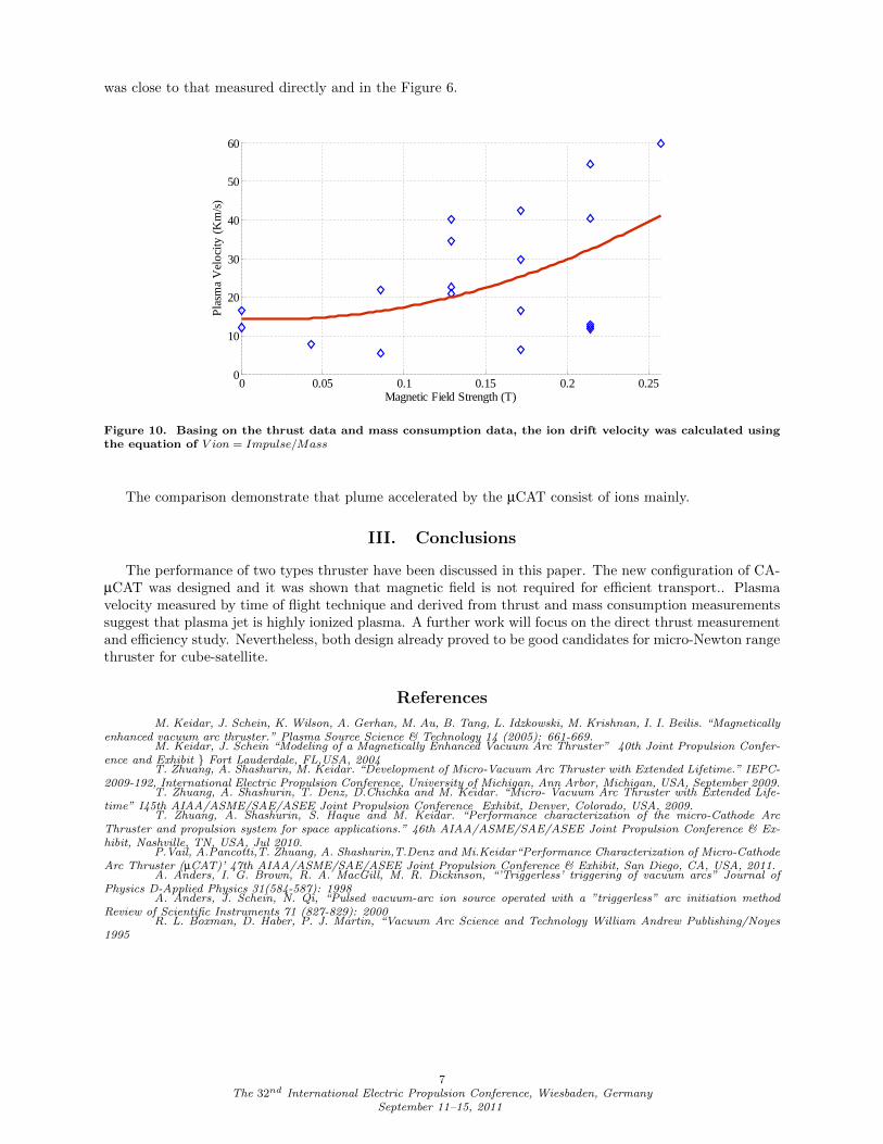
was close to that measured directly and in the Figure 6.
0 0.05 0.1 0.15 0.2 0.250
10
20
30
40
50
60
Magnetic Field Strength (T)
Pla
sma
Vel
ocity
(K
m/s
)
Figure 10. Basing on the thrust data and mass consumption data, the ion drift velocity was calculated usingthe equation of V ion = Impulse/Mass
The comparison demonstrate that plume accelerated by the µCAT consist of ions mainly.
III. Conclusions
The performance of two types thruster have been discussed in this paper. The new configuration of CA-µCAT was designed and it was shown that magnetic field is not required for efficient transport.. Plasmavelocity measured by time of flight technique and derived from thrust and mass consumption measurementssuggest that plasma jet is highly ionized plasma. A further work will focus on the direct thrust measurementand efficiency study. Nevertheless, both design already proved to be good candidates for micro-Newton rangethruster for cube-satellite.
References
M. Keidar, J. Schein, K. Wilson, A. Gerhan, M. Au, B. Tang, L. Idzkowski, M. Krishnan, I. I. Beilis. “Magneticallyenhanced vacuum arc thruster.” Plasma Source Science & Technology 14 (2005): 661-669.
M. Keidar, J. Schein “Modeling of a Magnetically Enhanced Vacuum Arc Thruster” 40th Joint Propulsion Confer-ence and Exhibit Fort Lauderdale, FL,USA, 2004
T. Zhuang, A. Shashurin, M. Keidar. “Development of Micro-Vacuum Arc Thruster with Extended Lifetime.” IEPC-2009-192, International Electric Propulsion Conference, University of Michigan, Ann Arbor, Michigan, USA, September 2009.
T. Zhuang, A. Shashurin, T. Denz, D.Chichka and M. Keidar. “Micro- Vacuum Arc Thruster with Extended Life-time” I45th AIAA/ASME/SAE/ASEE Joint Propulsion Conference Exhibit, Denver, Colorado, USA, 2009.
T. Zhuang, A. Shashurin, S. Haque and M. Keidar. “Performance characterization of the micro-Cathode ArcThruster and propulsion system for space applications.” 46th AIAA/ASME/SAE/ASEE Joint Propulsion Conference & Ex-hibit, Nashville, TN, USA, Jul 2010.
P.Vail, A.Pancotti,T. Zhuang, A. Shashurin,T.Denz and Mi.Keidar“Performance Characterization of Micro-CathodeArc Thruster (µCAT)’ 47th AIAA/ASME/SAE/ASEE Joint Propulsion Conference & Exhibit, San Diego, CA, USA, 2011.
A. Anders, I. G. Brown, R. A. MacGill, M. R. Dickinson, “’Triggerless’ triggering of vacuum arcs” Journal ofPhysics D-Applied Physics 31(584-587): 1998
A. Anders, J. Schein, N. Qi, “Pulsed vacuum-arc ion source operated with a ”triggerless” arc initiation methodReview of Scientific Instruments 71 (827-829): 2000
R. L. Boxman, D. Haber, P. J. Martin, “Vacuum Arc Science and Technology William Andrew Publishing/Noyes1995
7The 32nd International Electric Propulsion Conference, Wiesbaden, Germany
September 11–15, 2011