microcontroller digital blood pressure circuit
TRANSCRIPT

8/10/2019 Microcontroller Digital Blood Pressure Circuit
http://slidepdf.com/reader/full/microcontroller-digital-blood-pressure-circuit 1/88
Medical ApplicationsUser Guide
freescale.com/medical

8/10/2019 Microcontroller Digital Blood Pressure Circuit
http://slidepdf.com/reader/full/microcontroller-digital-blood-pressure-circuit 2/88

8/10/2019 Microcontroller Digital Blood Pressure Circuit
http://slidepdf.com/reader/full/microcontroller-digital-blood-pressure-circuit 3/88
freescale.com/medical
Introduction1.1 Freescale Offers Technology for Life . . . . . . . . . . . . . . . . . . . . . . . . . . . . . . . . . . . . . . . . .4
1.2 Welcome to Freescale Medical Solutions . . . . . . . . . . . . . . . . . . . . . . . . . . . . . . . . . . . . .4
Home Portable MedicalHome Portable Medical . . . . . . . . . . . . . . . . . . . . . . . . . . . . . . . . . . . . . . . . . . . . . . . . . . . . . . 5
2.1 Market and Devices. . . . . . . . . . . . . . . . . . . . . . . . . . . . . . . . . . . . . . . . . . . . . . . . . . . . . . . 5
Telehealth Systems . . . . . . . . . . . . . . . . . . . . . . . . . . . . . . . . . . . . . . . . . . . . . . . . . . . . . . . . . . 6
3.1 Introduction . . . . . . . . . . . . . . . . . . . . . . . . . . . . . . . . . . . . . . . . . . . . . . . . . . . . . . . . . . . . . 6
3.1.1 Power Management . . . . . . . . . . . . . . . . . . . . . . . . . . . . . . . . . . . . . . . . . . . . . . . . . . . . . 7
3.1.2 Voltage Regulation . . . . . . . . . . . . . . . . . . . . . . . . . . . . . . . . . . . . . . . . . . . . . . . . . . . . . . 8
3.1.3 Keypad . . . . . . . . . . . . . . . . . . . . . . . . . . . . . . . . . . . . . . . . . . . . . . . . . . . . . . . . . . . . . . . 9
3.1.4 Touch Sensing Software Suite . . . . . . . . . . . . . . . . . . . . . . . . . . . . . . . . . . . . . . . . . . . . 1 0
3.1.5 How it Works. . . . . . . . . . . . . . . . . . . . . . . . . . . . . . . . . . . . . . . . . . . . . . . . . . . . . . . . . . 10
3.1.6 Freescale Proximity Technology Summary. . . . . . . . . . . . . . . . . . . . . . . . . . . . . . . . . .10
3.1.7 PWM Function for a Speaker Circuit . . . . . . . . . . . . . . . . . . . . . . . . . . . . . . . . . . . . . .11
3.1.8 Wireless Communication . . . . . . . . . . . . . . . . . . . . . . . . . . . . . . . . . . . . . . . . . . . . . . . . 12
3.1.8.1 Introduction to ZigBee Technology. . . . . . . . . . . . . . . . . . . . . . . . . . . . . . . . . . . . . . .12
3.1.8 .2 Freescale Solut ions wi th ZigBee Technology . . . . . . . . . . . . . . . . . . . . . . . . . . . . . .12
3.1.8 .3 ZigBee Health Care Prof ile and IEEE 802.15.4 . . . . . . . . . . . . . . . . . . . . . . . . . . . . .13
3.1.8.4 Why ZigBee Is Ideal for Wireless Vital Sign Monitoring . . . . . . . . . . . . . . . . . . . . . .13
3.1.8.5 Freescale Enables ZigBee Health Care Profile for Medical Devices . . . . . . . . . . . .13
3.1.8.6 Transceivers and Receivers . . . . . . . . . . . . . . . . . . . . . . . . . . . . . . . . . . . . . . . . . . . . 1 3
3.1.9 Freescale Continua Health Alliance® Certified USB Library Software . . . . . . . . . . . .14
3.1.10 Standard Medical USB Communication . . . . . . . . . . . . . . . . . . . . . . . . . . . . . . . . . . .14
3.1.11 Additional Freescale Technologies . . . . . . . . . . . . . . . . . . . . . . . . . . . . . . . . . . . . . . .16
Blood Pressure Monitor . . . . . . . . . . . . . . . . . . . . . . . . . . . . . . . . . . . . . . . . . . . . . . . . . . . . .18
4.1 Introduction . . . . . . . . . . . . . . . . . . . . . . . . . . . . . . . . . . . . . . . . . . . . . . . . . . . . . . . . . . . . 18
4.2 Heartbeat Detection . . . . . . . . . . . . . . . . . . . . . . . . . . . . . . . . . . . . . . . . . . . . . . . . . . . . . 19
4.3 Systolic and Diastolic Measurements . . . . . . . . . . . . . . . . . . . . . . . . . . . . . . . . . . . . . . .19
4.4 Invasive Blood Pressure Monitors . . . . . . . . . . . . . . . . . . . . . . . . . . . . . . . . . . . . . . . . . . 1 9
4.5 O btaining P ressure M easures . . . . . . . . . . . . . . . . . . . . . . . . . . . . . . . . . . . . . . . . . . . . . . 20
4.6 Blood Pressure Monitor Reference Design . . . . . . . . . . . . . . . . . . . . . . . . . . . . . . . . . . .21
4.7 A dditional F reescale Technologies . . . . . . . . . . . . . . . . . . . . . . . . . . . . . . . . . . . . . . . . . . 2 2
Heart Rate Monitor . . . . . . . . . . . . . . . . . . . . . . . . . . . . . . . . . . . . . . . . . . . . . . . . . . . . . . . . . 23
5.1 Heart Signals Overview . . . . . . . . . . . . . . . . . . . . . . . . . . . . . . . . . . . . . . . . . . . . . . . . . . . 23
5.2 Filters and Amplification . . . . . . . . . . . . . . . . . . . . . . . . . . . . . . . . . . . . . . . . . . . . . . . . . . 24
5.3 Amplifier and Filtering Requirements . . . . . . . . . . . . . . . . . . . . . . . . . . . . . . . . . . . . . . . .25
5.4 Obtaining QRS Complexes . . . . . . . . . . . . . . . . . . . . . . . . . . . . . . . . . . . . . . . . . . . . . . . . 25
5.5. Additional Freescale Technologies . . . . . . . . . . . . . . . . . . . . . . . . . . . . . . . . . . . . . . . . .26
Fetal Heart Rate Monitor . . . . . . . . . . . . . . . . . . . . . . . . . . . . . . . . . . . . . . . . . . . . . . . . . . . .27
6.1 Doppler Fetal Heart Rate Monitor. . . . . . . . . . . . . . . . . . . . . . . . . . . . . . . . . . . . . . . . . . . 2 7
6.2 Ultrasonic Probe . . . . . . . . . . . . . . . . . . . . . . . . . . . . . . . . . . . . . . . . . . . . . . . . . . . . . . . . 28
6.3 Electrical Protection . . . . . . . . . . . . . . . . . . . . . . . . . . . . . . . . . . . . . . . . . . . . . . . . . . . . . 28
6.4 Signal Conditioning . . . . . . . . . . . . . . . . . . . . . . . . . . . . . . . . . . . . . . . . . . . . . . . . . . . . . . 28
6.5 A dditional F reescale Technologies . . . . . . . . . . . . . . . . . . . . . . . . . . . . . . . . . . . . . . . . . . 3 0
Blood Glucose Meter . . . . . . . . . . . . . . . . . . . . . . . . . . . . . . . . . . . . . . . . . . . . . . . . . . . . . . . 31
7.1 Introduction . . . . . . . . . . . . . . . . . . . . . . . . . . . . . . . . . . . . . . . . . . . . . . . . . . . . . . . . . . . . 31
7.2 Test Strip . . . . . . . . . . . . . . . . . . . . . . . . . . . . . . . . . . . . . . . . . . . . . . . . . . . . . . . . . . . . . . 32
7.3 Wired and Wireless Communication. . . . . . . . . . . . . . . . . . . . . . . . . . . . . . . . . . . . . . . . . 3 3
7.4 Liquid Crystal Display (LCD) Module . . . . . . . . . . . . . . . . . . . . . . . . . . . . . . . . . . . . . . . . 3 3
7.5 Inertial Sensor . . . . . . . . . . . . . . . . . . . . . . . . . . . . . . . . . . . . . . . . . . . . . . . . . . . . . . . . . . 34
7.6 A dditional F reescale Technologies . . . . . . . . . . . . . . . . . . . . . . . . . . . . . . . . . . . . . . . . . . 3 5
Pulse Oximetry . . . . . . . . . . . . . . . . . . . . . . . . . . . . . . . . . . . . . . . . . . . . . . . . . . . . . . . . . . . . . 36
8.1 Theory Overview . . . . . . . . . . . . . . . . . . . . . . . . . . . . . . . . . . . . . . . . . . . . . . . . . . . . . . . . 36
8.2 Signal Acquisition . . . . . . . . . . . . . . . . . . . . . . . . . . . . . . . . . . . . . . . . . . . . . . . . . . . . . . . 37
8.3 Circuit Design Overview . . . . . . . . . . . . . . . . . . . . . . . . . . . . . . . . . . . . . . . . . . . . . . . . . . 37
8.3.1 Circuit LED Driver . . . . . . . . . . . . . . . . . . . . . . . . . . . . . . . . . . . . . . . . . . . . . . . . . . . . . . 37
8.3.2 Signal Processing . . . . . . . . . . . . . . . . . . . . . . . . . . . . . . . . . . . . . . . . . . . . . . . . . . . . . . 38
Hearing Aids. . . . . . . . . . . . . . . . . . . . . . . . . . . . . . . . . . . . . . . . . . . . . . . . . . . . . . . . . . . . . . . . 40
9.1 Introduction . . . . . . . . . . . . . . . . . . . . . . . . . . . . . . . . . . . . . . . . . . . . . . . . . . . . . . . . . . . . 40
9.2 Microphone Amplifier . . . . . . . . . . . . . . . . . . . . . . . . . . . . . . . . . . . . . . . . . . . . . . . . . . . . 41
9.3 Li-ion Battery Charger Circuit . . . . . . . . . . . . . . . . . . . . . . . . . . . . . . . . . . . . . . . . . . . . . . 4 1
9.4 Class D Amplifier . . . . . . . . . . . . . . . . . . . . . . . . . . . . . . . . . . . . . . . . . . . . . . . . . . . . . . . . 42
9.5 Digital Signal Processor . . . . . . . . . . . . . . . . . . . . . . . . . . . . . . . . . . . . . . . . . . . . . . . . . . 42
9.6 A dditional F reescale Technologies . . . . . . . . . . . . . . . . . . . . . . . . . . . . . . . . . . . . . . . . . . 4 3
Diagnostic and Therapy DevicesDiagnostic and Therapy Devices. . . . . . . . . . . . . . . . . . . . . . . . . . . . . . . . . . . . . . . . . . . . . 44
10.1 Introduction . . . . . . . . . . . . . . . . . . . . . . . . . . . . . . . . . . . . . . . . . . . . . . . . . . . . . . . . . . . 44
10.2 Electrocardiograph and Portable ECG. . . . . . . . . . . . . . . . . . . . . . . . . . . . . . . . . . . . . .45
10.3 QRS Complex. . . . . . . . . . . . . . . . . . . . . . . . . . . . . . . . . . . . . . . . . . . . . . . . . . . . . . . . . . 45
10.4 Filtering ECG . . . . . . . . . . . . . . . . . . . . . . . . . . . . . . . . . . . . . . . . . . . . . . . . . . . . . . . . . . 46
10.5 Electrodes Interface. . . . . . . . . . . . . . . . . . . . . . . . . . . . . . . . . . . . . . . . . . . . . . . . . . . . . 46
10.6 Display Driver and Touch Screen Control ler . . . . . . . . . . . . . . . . . . . . . . . . . . . . . . . . .47
10.7 Enhanced Mul tiply-Accumulate (eMAC) Module. . . . . . . . . . . . . . . . . . . . . . . . . . . . . .47
10.8 USB Connection . . . . . . . . . . . . . . . . . . . . . . . . . . . . . . . . . . . . . . . . . . . . . . . . . . . .
10.9 Additional Freescale Technologies . . . . . . . . . . . . . . . . . . . . . . . . . . . . . . . . . . . . . .
Defibrillators. . . . . . . . . . . . . . . . . . . . . . . . . . . . . . . . . . . . . . . . . . . . . . . . . . . . . . . . . . . . .
11.1 Automated External Defibrillator (AED) . . . . . . . . . . . . . . . . . . . . . . . . . . . . . . . . . .
11.2 Circui t for Capacitive Discharge Def ibril lators. . . . . . . . . . . . . . . . . . . . . . . . . . . . .
11.3 Circui t for Rectangular-Wave Def ibril lators . . . . . . . . . . . . . . . . . . . . . . . . . . . . . . .
11.4 Additional Freescale Technologies . . . . . . . . . . . . . . . . . . . . . . . . . . . . . . . . . . . . . .
Ventilation and Spirometry . . . . . . . . . . . . . . . . . . . . . . . . . . . . . . . . . . . . . . . . . . . . . . .
12.1 Introduction . . . . . . . . . . . . . . . . . . . . . . . . . . . . . . . . . . . . . . . . . . . . . . . . . . . . . . . .12.2 System Sensors . . . . . . . . . . . . . . . . . . . . . . . . . . . . . . . . . . . . . . . . . . . . . . . . . . . . .
12.3 Spirometer . . . . . . . . . . . . . . . . . . . . . . . . . . . . . . . . . . . . . . . . . . . . . . . . . . . . . . . . .
12.4 Graphic LCD MPU . . . . . . . . . . . . . . . . . . . . . . . . . . . . . . . . . . . . . . . . . . . . . . . . . . .
12.5 Alarm System. . . . . . . . . . . . . . . . . . . . . . . . . . . . . . . . . . . . . . . . . . . . . . . . . . . . . . .
12.6 Air and Oxygen Blender and Mix Control. . . . . . . . . . . . . . . . . . . . . . . . . . . . . . . . .
12.7 Additional Freescale Technologies . . . . . . . . . . . . . . . . . . . . . . . . . . . . . . . . . . . . . .
Anesthesia Unit Monitor . . . . . . . . . . . . . . . . . . . . . . . . . . . . . . . . . . . . . . . . . . . . . . . . . .
13.1 Introduction . . . . . . . . . . . . . . . . . . . . . . . . . . . . . . . . . . . . . . . . . . . . . . . . . . . . . . . .
13.2 Brief Theory . . . . . . . . . . . . . . . . . . . . . . . . . . . . . . . . . . . . . . . . . . . . . . . . . . . . . . . .
13.3 Pressure Sensor. . . . . . . . . . . . . . . . . . . . . . . . . . . . . . . . . . . . . . . . . . . . . . . . . . . . .
13.4 Valve Control . . . . . . . . . . . . . . . . . . . . . . . . . . . . . . . . . . . . . . . . . . . . . . . . . . . . . . .
13.5 Principal MCU . . . . . . . . . . . . . . . . . . . . . . . . . . . . . . . . . . . . . . . . . . . . . . . . . . . . . .
Vital Signs . . . . . . . . . . . . . . . . . . . . . . . . . . . . . . . . . . . . . . . . . . . . . . . . . . . . . . . . . . . . . . .
14.1 Introduction . . . . . . . . . . . . . . . . . . . . . . . . . . . . . . . . . . . . . . . . . . . . . . . . . . . . . . . .
14.2 Measuring Temperature. . . . . . . . . . . . . . . . . . . . . . . . . . . . . . . . . . . . . . . . . . . . . . .
14.3 ECG Monitoring . . . . . . . . . . . . . . . . . . . . . . . . . . . . . . . . . . . . . . . . . . . . . . . . . . . . .
14.4 Pulse Oximetry Monitoring . . . . . . . . . . . . . . . . . . . . . . . . . . . . . . . . . . . . . . . . . . . .14.5 Blood Pressure Monitoring . . . . . . . . . . . . . . . . . . . . . . . . . . . . . . . . . . . . . . . . . . . .
14.6 Motor Control with Freescale Devices . . . . . . . . . . . . . . . . . . . . . . . . . . . . . . . . . . .
14.7 Additional Freescale Technologies . . . . . . . . . . . . . . . . . . . . . . . . . . . . . . . . . . . . . .
Intelligent HospitalsIntelligent Hospitals . . . . . . . . . . . . . . . . . . . . . . . . . . . . . . . . . . . . . . . . . . . . . . . . . . . . . .
15.1 Introduction . . . . . . . . . . . . . . . . . . . . . . . . . . . . . . . . . . . . . . . . . . . . . . . . . . . . . . . .
15.2 Hospital Admission Machine. . . . . . . . . . . . . . . . . . . . . . . . . . . . . . . . . . . . . . . . . . .
15.3 Patient Height and Weight . . . . . . . . . . . . . . . . . . . . . . . . . . . . . . . . . . . . . . . . . . . .
15.4 Patient Interface. . . . . . . . . . . . . . . . . . . . . . . . . . . . . . . . . . . . . . . . . . . . . . . . . . . . .
15.5 Communication Interfaces . . . . . . . . . . . . . . . . . . . . . . . . . . . . . . . . . . . . . . . . . . . .
15.6 Backlight Inverter. . . . . . . . . . . . . . . . . . . . . . . . . . . . . . . . . . . . . . . . . . . . . . . . . . . .
15.7 Multimedia Applications with i.MX53 . . . . . . . . . . . . . . . . . . . . . . . . . . . . . . . . . . . .
15.8 Additional Freescale Technologies . . . . . . . . . . . . . . . . . . . . . . . . . . . . . . . . . . . . . .
Powered Patient Bed . . . . . . . . . . . . . . . . . . . . . . . . . . . . . . . . . . . . . . . . . . . . . . . . . . . .
16.1 Introduction . . . . . . . . . . . . . . . . . . . . . . . . . . . . . . . . . . . . . . . . . . . . . . . . . . . . . . . .
16.2 Using Motors for Patient Positioning . . . . . . . . . . . . . . . . . . . . . . . . . . . . . . . . . . . .
16.3 Integrated Real-Time Patient Monitoring . . . . . . . . . . . . . . . . . . . . . . . . . . . . . . . . .
16.4 Integrated Tilt Control . . . . . . . . . . . . . . . . . . . . . . . . . . . . . . . . . . . . . . . . . . . . . . . .
16.5 Integrated Intercom Using VoIP . . . . . . . . . . . . . . . . . . . . . . . . . . . . . . . . . . . . . . . .
16.6 Additional Freescale Technology . . . . . . . . . . . . . . . . . . . . . . . . . . . . . . . . . . . . . . .
Medical ImagingMedical Imaging . . . . . . . . . . . . . . . . . . . . . . . . . . . . . . . . . . . . . . . . . . . . . . . . . . . . . . . . .
17.1 Introduction . . . . . . . . . . . . . . . . . . . . . . . . . . . . . . . . . . . . . . . . . . . . . . . . . . . . . . . .
17.2 Ultrasound . . . . . . . . . . . . . . . . . . . . . . . . . . . . . . . . . . . . . . . . . . . . . . . . . . . . . . . . .
17.3 How Ultrasound Works . . . . . . . . . . . . . . . . . . . . . . . . . . . . . . . . . . . . . . . . . . . . . . .
17.4 Transducer . . . . . . . . . . . . . . . . . . . . . . . . . . . . . . . . . . . . . . . . . . . . . . . . . . . . . . . . .
17.5 Multiplexer for Tx/Rx Transducers . . . . . . . . . . . . . . . . . . . . . . . . . . . . . . . . . . . . . .
17.6 Instrumentation Amplifier and Variable Gain Amplif ier . . . . . . . . . . . . . . . . . . . . . .
17.7 Beamformer . . . . . . . . . . . . . . . . . . . . . . . . . . . . . . . . . . . . . . . . . . . . . . . . . . . . . . . .
17.8 Microprocessors . . . . . . . . . . . . . . . . . . . . . . . . . . . . . . . . . . . . . . . . . . . . . . . . . . . .
17.9 Digital X-Ray . . . . . . . . . . . . . . . . . . . . . . . . . . . . . . . . . . . . . . . . . . . . . . . . . . . . . . .
17.10 Analog Front End . . . . . . . . . . . . . . . . . . . . . . . . . . . . . . . . . . . . . . . . . . . . . . . . . . .
17.11 Photo Detector Grid . . . . . . . . . . . . . . . . . . . . . . . . . . . . . . . . . . . . . . . . . . . . . . . .17.12 DSP/DSC . . . . . . . . . . . . . . . . . . . . . . . . . . . . . . . . . . . . . . . . . . . . . . . . . . . . . . . . .
17.13 Capacitive Sensing and Touch Screen Display . . . . . . . . . . . . . . . . . . . . . . . . . . .
Summary Appendix
Digital Signal Processing Concepts . . . . . . . . . . . . . . . . . . . . . . . . . . . . . . . . . . . . . . . . .
Digital Filter Examples. . . . . . . . . . . . . . . . . . . . . . . . . . . . . . . . . . . . . . . . . . . . . . . . . . . .
Freescale Technologies . . . . . . . . . . . . . . . . . . . . . . . . . . . . . . . . . . . . . . . . . . . . . . . . . . .
Instrumentation Amplifier . . . . . . . . . . . . . . . . . . . . . . . . . . . . . . . . . . . . . . . . . . . . . . . . .
Filter Design . . . . . . . . . . . . . . . . . . . . . . . . . . . . . . . . . . . . . . . . . . . . . . . . . . . . . . . . . . . .
Medical Perspective . . . . . . . . . . . . . . . . . . . . . . . . . . . . . . . . . . . . . . . . . . . . . . . . . . . . .
Table of Contents
8/10/2019 Microcontroller Digital Blood Pressure Circuit
http://slidepdf.com/reader/full/microcontroller-digital-blood-pressure-circuit 4/88
Medical Applications User Guide
1.1
Freescale Offers Technology for Life
According to a recent study by the U.S. Centers for Disease Control (CDC),
modern medical breakthroughs have raised the average global life expectancy
in developed nations to over 75 years1. As public health has advanced and
new pharmaceutical drugs have been developed, the prospect of prevalent
pathologies has also changed. Where once viral and bacterial infections were th
leading concerns of clinicians, today chronic and degenerative diseases are the
most worrisome. The World Health Organization predicts that by 2030 the two
leading causes of death will be heart disease and cancer by a wide margin2.
Freescale believes that semiconductor technology will play a critical role in the
development of new technologies that assist with patient monitoring, diagnostics,
therapy and imaging. Freescale is focused on what we can do as a semiconducto
company to help provide people a more healthy and active life. By designing
products with the highest safety and reliability standards, medical devices running
with Freescale components work when it counts. Electronic components behind
future medical devices are not seen by everyone, but we recognize that they work
to benefit people who are in contact with this technology. This is what is meant
when we say, “Freescale offers technology for life.”
1.2
Welcome to Freescale Medical Solutions
Freescale has focused on solving some of the world’s most important technolog
challenges for over 50 years. Whether the question has been how cell phones
can connect people across the world or how to harmonize all of the safety
features in a car, Freescale microcontrollers have been part of the solution. At
Freescale we bring that same drive and innovation to the medical industry.
The convergence of an aging population and breakthrough technological
advances has created endless opportunities for automated medical devices.
These devices help ensure the future health of millions of people by providing
advances in home health care, clinical activities and medical imaging. Regardles
of the end use, developers of medical devices face similar problems. The need
to balance processing requirements with power consumption helps to ensure a
fast time to market. Navigating the regulatory environment is common with all
medical applications.
At Freescale we offer a wide range of products so that developers can choose
processors, analog and sensor components or RF amplifiers to meet the unique
needs of their designs. Developers of medical technology face many challenges
today. Freescale believes that having the right silicon should not be one of them
ntroduction
1) CDC, U.S National Center for Health Statistics2) World Health Organization www.who.int/research/en/
Introduction
Back to Table of Contents

8/10/2019 Microcontroller Digital Blood Pressure Circuit
http://slidepdf.com/reader/full/microcontroller-digital-blood-pressure-circuit 5/88
freescale.com/medical
Home Portable Medical
2.1
Market and DevicesThe home portable medical market is one of the fastest growing
markets in the medical device industry3. The consumer population is
more health-conscious than ever before. This is reflected in devices
that are now common in the home, like portable heart rate monitors,
digital thermometers, electronic blood glucose meters and weight
scales that also measure body fat4. As clinicians look for new ways to
monitor patients in their natural environment, new telehealth devices
are being invented5.
These home portable medical devices share the common need for
long battery life, robust data processing and a wired or wireless
communication interface. Freescale microcontrollers also offer an
ideal combination of high processing capabilities and low power
consumption. As a pioneer in the communications market, Freescale
offers solutions for wired and wireless interfaces, including USB,
IEEE® 802.15.4 and ZigBee® technology. Furthermore, Freescale
microelectromechanical system (MEMS)-based pressure and inerti
sensors can be used to acquire physical parameters. User interfac
include touch screens, enabled by proximity sensors, that have ea
to-clean buttons and screens that can be sanitized quickly and ea
Freescale also offers a focused integrated analog portfolio that ena
maximum battery life with power management ICs that allow a pre
and accurate conversion of natural continuous signals to digital sig
that microcontrollers can process. Medical device customers can
engage with Freescale custom product groups for specific solution
that leverage our core competencies in precision analog, mixed sig
and power management technologies.
3) Databeans and Semicast 2008.4) www.who.int/medical_devices/en/
5) World Health Organization, www.who.int/goe/ehir/trends/en/
Home Portable Medi
Back to Table of Contents

8/10/2019 Microcontroller Digital Blood Pressure Circuit
http://slidepdf.com/reader/full/microcontroller-digital-blood-pressure-circuit 6/88

8/10/2019 Microcontroller Digital Blood Pressure Circuit
http://slidepdf.com/reader/full/microcontroller-digital-blood-pressure-circuit 7/88
freescale.com/medical
Home Portable Medi
3.1.1
Power ManagementEvery design needs a power source. If the
power source is not stable, the system may
fail while processing information. If the power
source is not regulated, the system may get
damaged. These failures might cause risks
to the patient. Therefore, the design and
implementation of a stable and regulated
power management system must be carefully
considered to mitigate these risks. Freescale’s
MC34712, MC34713, MC34716 and MC34717
are highly integrated, space-efficient, cost-
effective dual and single synchronous buck
switching regulators for multiple applications.
A typical application for these devices is
shown in Figure 3-2.
Key Features
• Integrated N-channel power MOSFETs input
voltage operating range from 3.0V to 6.0V
• 1% accurate output voltage, ranging from
0.7V to 3.6V
• Voltage tracking capability in different
configurations
• Programmable switching frequency range
from 200 kHz to 1.0 MHz with a default of
1.0 MHz
• Programmable soft start timing
• Over current limit and short circuitprotection
• Thermal shutdown
• Output overvoltage and undervoltage
detection
• Active low power, good output signal
• Active low shutdown input
The use of these regulators allows the use
of multiple power sources such as batteries,
chargers or AC adapters.
MCU Optional Peripherals Analog Sensors
Power
Management
Voltage
Regulation
MCU/MPU
Keypad USB
and/or Ethernet
Speaker
WirelessComm
IR Interface
PC/Broadband o
POTS connection
Display
PWM
Figure 3-1: Telehealth Gateway
Figure 3-2: MC34713 Simplified Application Diagram
VIN
VREFIN
PGND
VDDI
FREQ
ILIM
GND
PVIN
BOOT
SW
INV
COMP
VOUT
PG
SD
V MASTER
VIN
VOUT
MC34713
Microcontroller,
DSP,
FPGA,
ASIC
V IN(3.0V–6.0V)
Back to Table of Contents

8/10/2019 Microcontroller Digital Blood Pressure Circuit
http://slidepdf.com/reader/full/microcontroller-digital-blood-pressure-circuit 8/88
Medical Applications User Guide
Home Portable Medical
.1.2
Voltage Regulation
n systems where an MCU or DSP are used,
he power source must be able to provide
he complete range of voltage values to be
pplied to multiple VCC pins.
his regulation can be implemented using the
reescale MPC18730 power management
evice. This device regulates five independent
utput voltages from either a single Li-Ion cell
2.7V to 4.2V input range), a single-cell Ni-MH
r dry cell (0.9V to 2.2V input range).
MPC18730
he MPC18730 is a 1.15V/2.4 V 2-ch.
DC-to-DC converter with three low-dropout
egulators. Key features include:
Operates from single-cell Li-ion, Ni-MH oralkaline battery
Two DC-DC converters
Three low-dropout regulators
Serial interface sets output voltages
Four wake inputs
Low current standby mode
Regulation can also be implemented using the
reescale MC34704, a multi-channel power
management IC (PMIC) used to address power
management needs for various multimedia
pplication microprocessors such as Freescale’s
ARM® core-based i.MX processor family.
s ability to provide either five or eight
ndependent output voltages with a single input
ower supply (2.7V and 5.5V), together with
s high efficiency, makes it ideal for portable
evices powered by Li-ion and polymer
atteries or for USB powered devices.
MC34704
he MC34704 is a multi-channel PMIC. Key
eatures include:
Eight DC/DC (34704A) or five DC/DC
(34704B) switching regulators with up to
±2% output voltage accuracy
Dynamic voltage scaling on all regulators
Selectable voltage mode control or current
mode control on REG8
I2C programmability
Output under-voltage and over-voltage
detection for each regulator
Figure 3-3: Block Diagram Using Power Regulators
Battery Charger
AC Adapter Other Blocks
Other Blocks
+
-Battery
AC Line
MC34713
Regulated Power Source
MCU
VB
VREF
RSTO1B
EXT_G_ON
RSTO2B
CONTROL
LOGIC
INPUTS
GND
PGND
VCC1
VO1
SW1
VCC2
VO2
SW2
SREGI1SREGO1
SREGI2
SREGO2
SREGI3
SREGO3
VG
SWG
MC347132.7 to 4.2V input VB
Programmable1.613V to 3.2V
Programmable0.805V to 1.5V
Programmable0.865V to 2.8V
Programmable0.011V to 2.8V
Programmable2.08V to 2.8V
VB
VO
VO
MCU
Figure 3-5: Single Synchronous Buck Switching Regulator
Figure 3-4: Lineal Voltage Regulator
Vout Vin
1uF 0.1uF
E S
T
+ +
Back to Table of Contents

8/10/2019 Microcontroller Digital Blood Pressure Circuit
http://slidepdf.com/reader/full/microcontroller-digital-blood-pressure-circuit 9/88
freescale.com/medical
Home Portable Medi
• Over-current limit detection and short-
circuit protection for each regulator
• Thermal limit detection for each regulator
(except REG7)
• Integrated compensation for REG1, REG3,
REG6 and REG8
• 5 µA maximum shutdown current (all
regulators are off, 5.5V VIN)
• True cutoff on all boost and buck-boost
regulators
3.1.3
Keypad A keypad can be implemented using touch
sensing. This technology has advantages over
classic button-based technology, including:
• Cost effectiveness
• Smaller design
• More durability because there is virtually no
mechanical wear
• Easy to keep clean
Freescale provides software libraries that
implement touch-sensing algorithms using a
microcontroller’s general-purpose pins. The
software allows the microcontroller to drive
up to 64 touch pads. It needs only one pull-up
resistor per electrode and timer to complete
the circuit.
Freescale’s MPR031, MPR032, MPR083 and
MPR084 can also provide a cost-effective
solution in a single-chip capacitive touch
sensing controller. These devices can be
connected to an MCU through an I2C interface.
MPR084
The MPR084 is an eight-pad touch sensor
controller. Key features include:
• Current touch pad position is available on
demand for polling-based systems
• Rejects unwanted multi-key detections
from EMI events such as PA bursts or user
handling
• Ongoing pad analysis and detection is not
reset by EMI events
• System can set interrupt behavior
immediately after event, or program
a minimum time between successive
interrupts
• Sounder output can be enabled to generate
a key-click sound when the rotary is
touched
• Two hardware-selectable I2C addresses
allow two devices on a single I2C bus
MPR083
The MPR083 is a capacitive touch sensor
controller, optimized to manage an 8-position
rotary shaped capacitive array. Key features
include:
• Variable low power mode response time
(32 ms–4s)
• Rejects unwanted multi-key detections
from EMI events such as PA bursts or user
handling
• Ongoing pad analysis and detection is
reset by EMI events
• Data is buffered in a FIFO for shortest
access time
• IRQ output advises when FIFO has dat
• System can set interrupt behavior as
immediate after event, or program a
minimum time between successive
interrupts
• Current rotary position is always availa
on demand for polling-based systems
• Sounder output can be enabled to gen
key-click sound when the rotary is touc
• Two hardware-selectable I2C addresses
allowing two devices on a single I2C bu
MC34704 Functional Internal Block DiagramFigure 3-6: MC34704 Block Diagram
Logic and Control
Startup Sequencing Soft-Start Control
VREF Generator Fault Register
I2C Communication and Registers
Fault Detection and Protection
Over-Voltage Under-Voltage
VREF Generator Short-Circuit
Over-Current
Gate Driver Voltage VG
Internal Bias Circuit Output Groups
*34704A 8-channel only
VREF Generator VDDI ReferenceRegulator 1* A
Regulator 2
Regulator 3
Regulator 4
B
Regulator 5*
Regulator 6*
Regulator 7*
C
Regulator 8D
Regulator 5E
Figure 3-7: Keypad Implementation Using Proximity Software
VDD
Pull-upresistor
up to64
GPIO port
Touch Pads
MCU with
Proximity Software
Back to Table of Contents

8/10/2019 Microcontroller Digital Blood Pressure Circuit
http://slidepdf.com/reader/full/microcontroller-digital-blood-pressure-circuit 10/88
0 Medical Applications User Guide
Home Portable Medical
.1.4
Touch-Sensing SoftwareSuite
he Touch-Sensing Software Suite (TSS) is a
ownloadable software package that enables
Freescale 8-bit MCU as a touch sensor. This
rovides cost-effective and flexible solutions
or human-machine interfaces. TSS is a
modular and layered software that enhances
orward compatibility and simplifies touch key
onfigurations. It also enables the integration
f connectivity, LCD, LED, audio and other
eripherals.
Key features of the software include:
Intellectual property (IP) ownership
in hardware layouts and software
implementations such as capacitance
conversion, key detection and decoding
algorithms
Modular software design to add new
algorithms
Easy to use with the simple and robust
API set, including algorithms, patents
and system implementations that protect
customer applications from noisy/not ideal
environments
Capability to coexist with customer
application code
Available application layer software, decoders
(rotary, slider, keypads), demonstrations and
reference designs to expedite customer time
to market
Possible to use different materials such as
electrodes, PCB, Flex PCB, membranes,
glasses and foams
.1.5
How it Workshe external capacitance is charged and
ischarged continuously. This depends on
he sample configuration. At the time the
apacitance is being charged the timer is
unning and counting. When the electrode
oltage reaches 0.7 VDD, the timer stops
nd the counter value is taken. The external
apacitance is modified at the touch
vent, modifying the time charge. When
he electrode is touched, the capacitance
ncreases. Therefore the count is higher. The
umber of samples taken is user-configurable
and determines how many times the
capacitance is charged and discharged when
the scanning starts.
A touch sensing system has the following
components:
• Electrodes: Physical area that the user uses
as the interface. Usually made of PCB or
indium tin oxide (ITO)
• Capacitance to digital converter: Measures
capacitance on each electrode and
produces a digital value as output
• Signal processing stage: This stage
translates measured capacitance to touch
status and then to a logic behavior (rotary,
keypad, slider and so on)
• Output: Indicates touch detection both to
the user and the application
3.1.6
Freescale ProximityTechnology Summary
• Extra hardware (except for pull-up resistors)
is not necessary with Freescale TSS. The
host’s TSS code is required to process and
perform more. Each touch pad must be
connected to one GPIO on the MCU.
• This is a two-chip solution. Because of
the I2C interface, capacitive touch sensing
controllers allow the number of electrodes
to be expanded by using two pins of the
MCU.
Figure 3-8: Keypad Implementation Using Capacitive Touch Sensing Controllers
MCU
VDD
Pull-upresistor
MPRO84
MPRO31MPRO32
MPRO83
8
GPIOport
SDA I2C bus
SCL
8 Touch Pads
3 Touch Pads
8 Position Rotary
1
5
2
37
8
46
VDD
Pull-upresistor
8
3
75K
Figure 3-9: Components of a Touch Sensing System
E1
Buzzer Feedback to
User
Output
Capacitance
to Digital
Converter
Signal
Processing
Stage
E2
En
Back to Table of Contents
8/10/2019 Microcontroller Digital Blood Pressure Circuit
http://slidepdf.com/reader/full/microcontroller-digital-blood-pressure-circuit 11/88
freescale.com/medical
Home Portable Medi
• MPR083 and MPR084 can drive up to eight
electrodes each. Each electrode needs a
pull-up resistor.
• MPR031 and MPR032 are ultra-small touch
sensing controllers that support up to
three electrodes. They need one external
component and do not need pull-up
resistors in the electrodes.
Information about touch-sensing technology and
the application note titled 3-Phase AC Motor
Control with V/Hz Speed Closed Loop Using the
56F800/E (document AN1958), which provides
information about touch panel applications, can
be found at freescale.com.
3.1.7
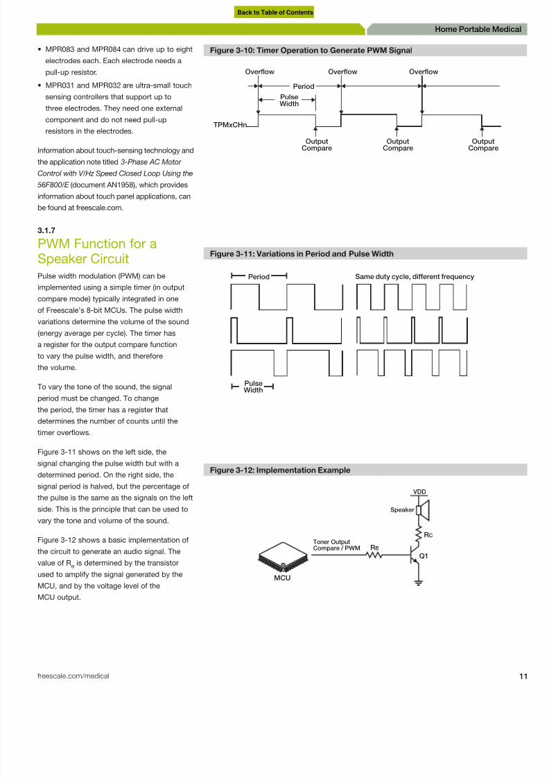
PWM Function for aSpeaker CircuitPulse width modulation (PWM) can be
implemented using a simple timer (in output
compare mode) typically integrated in one
of Freescale’s 8-bit MCUs. The pulse width
variations determine the volume of the sound
(energy average per cycle). The timer has
a register for the output compare function
to vary the pulse width, and therefore
the volume.
To vary the tone of the sound, the signal
period must be changed. To change
the period, the timer has a register that
determines the number of counts until the
timer overflows.
Figure 3-11 shows on the left side, the
signal changing the pulse width but with a
determined period. On the right side, the
signal period is halved, but the percentage of
the pulse is the same as the signals on the left
side. This is the principle that can be used to
vary the tone and volume of the sound.
Figure 3-12 shows a basic implementation of
the circuit to generate an audio signal. The
value of RB is determined by the transistor
used to amplify the signal generated by the
MCU, and by the voltage level of the
MCU output.
Figure 3-10: Timer Operation to Generate PWM Signal
Overflow
TPMxCHn
OutputCompare
PulseWidth
Period
OutputCompare
OutputCompare
Overflow Overflow
Figure 3-11: Variations in Period and Pulse Width
Period Same duty cycle, different frequency
PulseWidth
Figure 3-12: Implementation Example
MCU
Toner OutputCompare / PWM
Speaker
VDD
Q1
RB
RC
Back to Table of Contents

8/10/2019 Microcontroller Digital Blood Pressure Circuit
http://slidepdf.com/reader/full/microcontroller-digital-blood-pressure-circuit 12/88
2 Medical Applications User Guide
Home Portable Medical
.1.8
Wireless CommunicationOffering a broad portfolio of RF products,
reescale primarily serves the wireless
nfrastructure, wireless subscriber, general
urpose amplifier, broadcast and industrial
markets. Freescale pioneered RF technology
nd continues to be a leader in the field
y providing the quality, reliability and
onsistency that is associated with our RF
roducts.
.1.8.1
ntroduction to ZigBeeTechnology
he ZigBee Alliance defines low-power
wireless communication protocol stacks and
rofiles designed for monitoring and control of
evices in a variety of markets and applications.
hese include consumer, smart energy, control
nd automation and medical markets. There are
wo different specifications (ZigBee and ZigBee
Consumer) as well as multiple profiles that focus
n specific markets. Freescale provides the
ecessary building blocks used for both ZigBee
nd ZigBee Consumer solutions, including
ardware, software, tools and reference designs.
.1.8.2
Freescale Solutions withZigBee Technology
he ZigBee protocol stack is designed for
monitoring and control applications such
s building automation and smart energy. It
eatures self-forming and self-healing mesh
etworks that help differentiate it from
ther technologies.
3.1.8.3
Configuration Diagramsfor Freescale ZigBeeTransceiver Families
Figure 3-13: MC1319x Family Block Diagram
Transceiver Impedance
Coupling
MC1319x
Switch
Figure 3-14: MC1320x Family Block Diagram
Transceiver
Impedance
Coupling
MC1320x
Switch
Figure 3-15: MC1321x Family Block Diagram
MCU and
Transceiver
Impedance
Coupling
MC1321x
Switch
Figure 3-16: MC1322x Family Block Diagram
Transceiver
ModuleImpedance
Coupling
MC1322x
MCU
Switch
Back to Table of Contents
8/10/2019 Microcontroller Digital Blood Pressure Circuit
http://slidepdf.com/reader/full/microcontroller-digital-blood-pressure-circuit 13/88
freescale.com/medical
Home Portable Medi
3.1.8.3
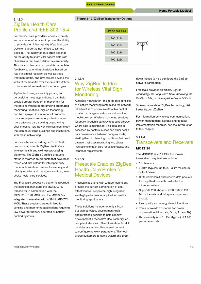
ZigBee Health CareProfile and IEEE 802.15.4For medical care providers, access to timely
and accurate information improves the ability
to provide the highest quality of patient care.
Decision support is not limited to just thebedside. The quality of care often depends
on the ability to share vital patient data with
clinicians in real time outside the care facility.
This means clinicians can provide immediate
feedback to attending physicians based on
real-life clinical research as well as track
treatment paths, and give results beyond the
walls of the hospital over the patient’s lifetime
to improve future treatment methodologies.
ZigBee technology is rapidly proving to
be useful in these applications. It can helpprovide greater freedom of movement for
the patient without compromising automated
monitoring functions. ZigBee technology
can be deployed in a number of products
that can help ensure better patient care and
more effective care tracking by providing
cost-effective, low-power wireless technology
that can cover large buildings and institutions
with mesh networking.
Freescale has received ZigBee® Certified
product status for its ZigBee Health Carewireless health and wellness processing
platforms. The ZigBee Certified products
status is awarded to products that have been
tested and met criteria for interoperability
that enable wireless devices to securely and
reliably monitor and manage noncritical, low-
acuity health care services.
The Freescale processing platforms awarded
the certification include the MC13202FC
transceiver in combination with the
MC9S08QE128 MCU, and the MC13224Vintegrated transceiver with a 32-bit ARM7™
MCU. These products are optimized for
sensing and monitoring applications requiring
low power for battery-operated or battery-
backed systems.
3.1.8.4
Why ZigBee Is Idealfor Wireless Vital SignMonitoring A ZigBee network for long-term care consists
of a patient monitoring system and the network
infrastructure to communicate with a central
location or caregiver station as well as other
mobile devices. Wireless monitoring provides
feedback through a gateway to a central server
where data is maintained. This data can be
accessed by doctors, nurses and other health
care professionals between caregiver visits,
alerting them to changing conditions that need
attention. Wireless monitoring also allows
institutions to track care for accountability andinsurance requirements.
3.1.8.5
Freescale Enables ZigBeeHealth Care Profile forMedical Devices
Freescale solutions with ZigBee technology
provide the perfect combination of cost
effectiveness, low power, high integration
and high performance required for medicalmonitoring applications.
These solutions include not only silicon
but also software, development tools
and reference designs to help simplify
development. Freescale’s BeeStack ZigBee-
compliant stack with BeeKit Wireless Toolkit
provides a simple software environment
to configure network parameters. This tool
allows customers to use a wizard and drop-
down menus to help configure the ZigBee
network parameters.
Freescale provides an article, ZigBee
Technology for Long-Term Care Improving
Quality of Life, in the magazine Beyond Bits
To learn more about ZigBee technology, v
freescale.com/ZigBee.
For information on wireless communicatio
power management, keypad and speaker
implementation modules, see the Introduc
to this chapter.
3.1.8.6
Transceivers and ReceivMC13191
The MC13191 is a 2.4 GHz low-power
transceiver. Key features include:
• 16 channels
• 0 dBm (typical), up to 3.6 dBm maximu
output power
• Buffered transmit and receive data pac
for simplified use with cost-effective
microcontrollers
• Supports 250 kbps O-QPSK data in 2.0
MHz channels and full spread-spectrum
encode
• Link quality and energy detect function
• Three power-down modes for power
conservation (Hibernate, Doze, Tx and
• Rx sensitivity of –91 dBm (typical) at 1.
packet error rate
Figure 3-17: ZigBee Transceiver Options
IEEE® 802.15.4
MC1319x
MC1320x
MC1321x
MC1322x
Back to Table of Contents

8/10/2019 Microcontroller Digital Blood Pressure Circuit
http://slidepdf.com/reader/full/microcontroller-digital-blood-pressure-circuit 14/88
4 Medical Applications User Guide
Home Portable Medical
.1.9
Freescale ContinuaHealth Alliance® CertifiedUSB Library SoftwareOne of the most considerable challenges
or medical designers is medical standard
ompliances. The Continua Health Alliance® www.continuaalliance.org) consists of more
han 200 members that have come together
o form work groups to set standards for
medical systems.
Having multi-vendor medical devices
ommunicating among themselves is not an
asy task. Every day, protocols such as USB
re being implemented in medical devices.
Continua provides guidelines to address
tandardization in connectivity.
igure 3-18 describes a medical device
ystem topology.
reescale provides complimentary stacks that
nable the user with ready-to-use software to
egin their path to standardization. Continua
Health Alliance is responsible for certifying
evices for compliance.
.1.10
Standard Medical USB
Communicationor USB communication, two main standards
must be considered:
IEEE 11073, which provides structure to the
communication interface
Personal health care device class (PHDC),
which is a standard implementation of USB
for medical devices
he advantage of designing medical
pplications with a dedicated medical stack
nstead of a conventional USB stack is thatmedical USB stack is designed specifically
or medical USB devices. It eases medical
pplication data exchange because it has a
pecific device specialization layer. Designing
medical applications under a conventional
USB stack may not provide the added value
f medical organizations’ certifications.
hree main factors need to be considered
when selecting a particular USB connectivity
oftware implementation for medical devices.
1. Standardization: The solution is based
on well-known standards in the industry.
This helps to ensure success and proper
introduction of the product to the market.
2. Connectivity: The implementation allows
connecting multiple devices from different
vendors within an ecosystem topology.
A connectivity-friendly environment is
sustained by a robust and easy-to-use
software stack.
3. Portability: Multi-device independent
layered architecture eases porting of code
among devices. Selecting a hardware
vendor with a broad portfolio is key to
ensure customization and product roadmap
establishment.
Software architecture ensures code
robustness, portability and reliability in
embedded systems development.
The medical applications USB stack provides
the user with a PHDC implementation thatis divided into layers for portability and
simplicity. The stack can also be used as a
general-purpose USB stack. The stack has
been ported to 8-bit 9S08 and 32-bit ColdFire
devices. The stack can be downloaded at
freescale.com.
The USB protocol can be further broken into
PHDC and low-level driver layers. The low-
level driver abstracts USB IP to provide a
generic interface to the class driver.
Figure 3-18: Continua Ecosystem Topology
Application Hosting Devices LAN/WANPAN Devices
Figure 3-19: Medical Applications USB Stack
Mouse Medical USBSeries Storage
HID PHD CDC MSD
S08 CF-V1 Controll
S08 CF-V1 Core
Device Layer
Hardware
Register
Controller
Device
Class
Back to Table of Contents

8/10/2019 Microcontroller Digital Blood Pressure Circuit
http://slidepdf.com/reader/full/microcontroller-digital-blood-pressure-circuit 15/88
freescale.com/medical
Home Portable Medi
The PHDC is a function-specific class layer.
Its responsibility is to hide transport-specific
details from the data exchange protocol layer.
Freescale additionally provides a Medical
Connectivity Library that provides users with
standard IEEE11073 connectivity. This library
is transport-independent because of its
transport independent layer (TIL). Therefore,
protocols that may be used include serial,
Bluetooth, USB and ZigBee. The library can
be downloaded at freescale.com.
USB devices compliant with industry
standards such as IEEE-11073 will be
developed under organizations such as
Continua Health Alliance for future use. A
sample application featuring a weight scale
device has been created to demonstrate the
value of working under the standardization
scheme and allowing multi-vendor device
interoperability. The demo videos are available
at freescale.com.
In the weight scale example, the personal
health care application interacts with the host
computer using IEEE 11073 – 20601 and
IEEE-11073 – 10415 (weight scale) protocols.
It is important to note that the host computer
runs the same IEEE 11073 protocols. One
specific example of such implementation
is covered by Continua Alliance. Member
companies of the Continua Alliance can obtain
CESL reference software. After installing this
software the host is emulated and ready to
connect to the weight scale device.
Freescale has developed sample code to
connect with the Continua Alliance emulator.
After flashing an 8-bit 9S08JM device with
this software, the device is recognized as
a Continua USB interface. The supplied
drivers allow the device to be recognized
as a USB personal health care device. The
Continua manager is then launched and
transport communication starts. The weight
measurements are sent from the 9S08JM
device to the host. Other personal health care
applications can also interact with the host
system developed by Continua. These include
IEEE 11073 – 10407 (blood pressure monitor
IEEE 11073 – 10417 (glucose meter) and IEEE
11073 – 10408 (thermometer) protocols.
Table 3-1. Freescale MCU Families that Support the USB Personal Health Care Device
SOC Use Case
S08
MC9S08JM16 Low-end PAN device
MC9S08JM60 PAN device
MC9S08JS16 Low-end PAN device
CFv1
MCF51JM128 PAN device
Hybrid device
Application hosting device
CFv2
MCF5225x PAN device
Hybrid device
Application hosting device
Figure 3-20: Broadband Block Diagram
Implant
Health Care
Provider
Service
Disease
Management
Service
Personal
Health Record
Service
Implant
Monitoring
Service
Cell Phone
Digital
Home
Internet
PC
Pulse
Ox
Blood-
Pressure
Cuff
Pedometer
Weight
Scale
Fitness
Equipment
USB Personal Health Care
Device Class Specification
MedicationTracking
Personal Health
System
Figure 3-21: Medical Connectivity Library (IEEE 11073)
USB Ethernet Transport
USB TCP/IP Transport
USB HW Ethernet Transport
Application
Device Specialization Interface
Medical Connectivity
Medical Connectivit
Library
Interface API
TIL SHIM
Interface API
Available Functionality
TIL Interface
Back to Table of Contents

8/10/2019 Microcontroller Digital Blood Pressure Circuit
http://slidepdf.com/reader/full/microcontroller-digital-blood-pressure-circuit 16/88
6 Medical Applications User Guide
Home Portable Medical
MPC8313E: PowerQUICC II Pro
Processor
he MPC8313E is a cost-effective, low-
ower, highly integrated processor. The
MPC8313E extends the PowerQUICC family,
dding higher CPU performance, additional
unctionality, and faster interfaces while
ddressing the requirements related to timeo marked, price, power consumption and
ackage size.
S08JS: 8-bit Microcontroller Family
he S08JS 8-bit microcontroller family features
full-speed 2.0 USB device controller and
ntegrates a USB transceiver to help save cost
y eliminating off-chip components.
Key features of this microcontroller family
nclude:
48 MHz HCS08 coreIntegrated full-speed USB 2.0 device
controller
16/8 KB flash, 512B SRAM, 256B USB
RAM 2.7V to 5.5V operation, -40°C to
+85°C operation
ROM-based USB bootloader
SCI, SPI, 8-channel KBI
16-bit timers: 1 x 2-channel
MTIM: 8-bit timer
One hardware CRC module
12 general-purpose I/O and two output-only
pins
Multiple purpose clock generation
24QFN, 20SOIC package options
.1.11
Additional FreescaleTechnologies
his table describes additional Freescale
evices that can be used for telehealth
pplications. Visit freescale.com to read thepplication notes or for more information
bout any of these devices.
Table 3-2. MPC8313E Processor Highlights
MPC8313 MPC8313E
Core e300, 2-IU, w/FPU, up to 400 Hz
L1 I/D cache 16 KI/16 KD
Memory controller 16/32-bit DDR2-333
Local bus controller 25-bit/8-bit dedicted or 25-bit/16-bit MUX Add/Data up to 66 MHz
PCI One 32-bit up to 66 MHz wake on PME
Ethernet Two 10/100/1000 MACs, SGMII. 98145.452
98145.452 One High-Speed USB 2.0 host/device+HS PHY, wake on USB
Security None SEC 2.2
UART Dual
I2C Dual
SPI 1
Boot options NOR, NAND
Internal controller PIC
MUX/dedicated GPIO 10/16
DMA 4 channels
Estimated core power 1.2W
Power management Standby power <300 mW
Figure 3-22: MPC8313E Block Diagram
Security
Acceleration
e300 Core
Complex
DDR/DDR2
SDRAM Controller
Local Bus
Performance Monitor,
DUART, I2C,
Timers, GPIO,
Interrupt Control
Coherent System Bus
2-lane SerDes
2x GigabitEthernet
SGMII
USB
ULPI PHY
PCI 4-ch.DMA
Core
Accelerators
I/O
Debugging/Interfaces Peripherals Flash RAM Core Plus Features
Figure 3-23: JS 16/8 Block Diagram
Memory
Options
6 KB
8 KB 512 KB SRAMFlash
SPI2-ch., 16-bit
Timer
ROM-BasedUSB Bootloader
ICE+BDM
MTIM
KBI
USB 2.0
SCI COP
RTC CRC
MCG
S08 Core
256BUSB RAM
Back to Table of Contents

8/10/2019 Microcontroller Digital Blood Pressure Circuit
http://slidepdf.com/reader/full/microcontroller-digital-blood-pressure-circuit 17/88
freescale.com/medical
Home Portable Medi
Table 3-3. Additional Freescale Technologies for Telehealth Systems
Device Description Key features Applications Application Notes
MPC5121e 32-bit embeddedprocessors
e300 core
400 MHz
760 MIPS
DDR
USB 2.0 OTG
• Telehealth
• Hospital Admission Machine
• Powered Patient Bed
AN3765: Porting Linux for the MPC5121e
AN2606: Working with Low-Frequency Oscillators
AN3763: Running a FIR Filter
AN3793: 3-D Graphics on the Using OpenGL ES
AN3805: MPC5121e SDHC Controller
AN3797: Integrated Programmable Interrupt Controller
MCF5445X 32-bit microprocessor MACs
I2S busDMA
USB OTG
DDR2/DDR
• Telehealth
• Hospital Admission Machine
AN3520: Simplied EHCI Data Structures
AN3631: Simplied Device Data Structures AN3517: Conguring the MCF5445x for PCI Host
AN3513: ColdFire ATA Host Controller
AN3522: DDR2 SDRAM on the ColdFire MCF5545x
MPC8313E PowerQUICC II Proprocessor
e300c3
2 IU with FPU
400 MHz
DMA
DDR2
USB 2.0 OTG
• Telehealth: Control System AN2583: Programming DDR SDRAM Controller
AN3533: Programming the User-Programmable Machine AN364SEC 2/3x Descriptor Programmer’s Guide
AN3830: Hardware Debugging Using the CodeWarrior IDE
AN3369: PowerQUICC DDR2 SDRAM Controller Register
AN2910: Hardware and Layout Design for DDR2 SDRAM
AN3359: Performance Monitor
AN3201: Using U-boot to Boot from a NAND Flash
MCF51QE Flexis 32-bit V1 ColdFiremicrocontroller
50 MHz V1 ColdFire coremicrocontroller, 25 MHz busspeed
• Telehealth
• Blood Pressure Monitors
• Heart Rate Monitor
• Fetal Heart Rate Monitor
• Blood Glucose Monitor
• Pulse Oximetry
• Portable ECG
AN3460: Low-Power Enabled by QE128 (S08 and MCF51)
AN3464: Migrating Code Between V1 and V2 ColdFire
AN3465: Migrating within the Controller Continuum
AN3500: Blood Pressure Monitor Using Flexis QE128 Device
AN3552: Analog Comparator Tips and Tricks
AN3586: Run uC/OS-II on MCF51QE128 AN3629: MC9S08QE32 to the MCF51QE32
S08JM 8-bit USBmicrocontroller
USB 2.0 full-speed device • Telehealth
• Heart Rate Monitor
• Blood Pressure
• Blood Glucose Monitor
• Pulse Oximetry
• Portable ECG
• Ventilation/Spirometry
• Vital Signs Monitoring
• Hospital Admission Machine
• X–Ray
• Anesthesia Unit Monitor
AN3756: Synchronizing Internal Clock for LIN Slave
AN3560: USB Device Development with MC9S08JM60
AN3561: USB Bootloader for the MC9S08JM60
AN3564: Customize the USB Application
AN3565: USB and Using the CMX USB Stack
AN3582: The USB Data Logger
MPC18730 1.15V/2.4V 2-ch.
DC-to-DC converters
with three low-dropoutregulators
Cell Li-ion, NI-MH andalkaline batteries
two DC-DC converters,serial sets output voltages
• Power Management AN1902: Quad Flat Pack No-Lead (QFN)
AN3247: Understanding and Using the Multi-Purpose MPC1873
MC13883 Integrated charger,USB On-The-Gotransceiver and carkitinterface
Li-ion battery chargingthrough a USB connector
• Power Management TECHOPTMLPMFS: Technologies for Optimized Power Manage
XTMENRGYCNSVWP: eXtreme Energy Conservation: AdvancedPower-Saving Software for Wireless Devices
MC34704 Multi-channel powermanagement IC(PMIC)
8 DC/DC (34704A) or 5 DC/ DC (34704B) switchingregulators
• Telehealth: Power Management AN3809: Freescale’s Power Management ICs
AN1902: Quad Flat Pack No-Lead (QFN)
AN3820: i.MX25 Power Management Using the MC34704
MPR083 8-position rotary Optimized to manage an8-position rotary shapedcapacitive array
• Touch and Proximity Interfaces AN3747: Pad Layout Application Note
AN1985: Touch Panel Applications Using the MC34940/MC3379E-Field IC
AN3583: Using Low Power Mode on the MPR083 and MPR084
MPR084 8-pad touch sensorcontroller
Optimized to manage an8-touch pad capacitive array
• Touch and Proximity Interfaces AN3761: Using Freescale Devices for Contactless Touch Applica
MC13191 2.4 GHz low-power
transceiver
Supports 250 kbps O-QPSK
data in 2.0 MHz channelsand full spread-spectrumencode
• Wireless Communication AN3381: Using SMAC with the HCS08QD4 MCU
AN2731: Compact Integrated Antennas AN2975: IEEE 802.15.4 and ZigBee Applications
AN2976: MC1319x RF Test Procedures
AN2935: MC1319x Coexistence in the 2.4 GHz ISM Band
AN2985: MC1319x Physical Layer Lab Test Description
AN2902: MC1319x Range Test
AN3231: SMAC Based Demonstration Applications
AN3251: Reference Oscillator Crystal Requirements
AN2825: Handling MAC Erasure
AN3577: Creating a USB-to-Wireless Bridge
Back to Table of Contents

8/10/2019 Microcontroller Digital Blood Pressure Circuit
http://slidepdf.com/reader/full/microcontroller-digital-blood-pressure-circuit 18/88
8 Medical Applications User Guide
Home Portable Medical
Blood Pressure Monitor
.1
ntroductionBlood pressure monitors are medical devices for patients who suffer
rom hypertension who need to detect, measure and track their bloodressure. This is one of the vital signs that need to be measured
o make a precise diagnosis. Up to 25 percent of patients who are
iagnosed with hypertension do not suffer from hypertension, but
nstead from white-coat hypertension. This is the elevation of arterial
ressure due to anxiety or stress produced by a health professional
while taking a blood pressure test. This is why personal blood pressure
monitors can help in detecting true hypertension as stipulated in the
oint National Committee and the 2003 guidelines from the European
ociety of Hypertension.
Blood pressure monitoring systems use techniques such as
oscillometric methods and Korotkoff measurements. The oscillometricmethod consists of measuring the oscillations in pressure inside the
cuff that the patient wears. The Korotkoff method is based on listening
to sounds when taking blood pressure.
Automatic blood pressure monitoring conducted at home is
increasingly used in the diagnosis and management of hypertension.
This includes arm cuff and wrist cuff units. Figure 4-1 illustrates the
system block diagram of a typical blood pressure monitor. This block
diagram and others like it are available on the Freescale medical
website, freescale.com/medical.
Home Portable Medical
Back to Table of Contents

8/10/2019 Microcontroller Digital Blood Pressure Circuit
http://slidepdf.com/reader/full/microcontroller-digital-blood-pressure-circuit 19/88
freescale.com/medical
Home Portable Medi
4.2
Heartbeat Detection
The heartbeat rate is considered one of the
vital patient measurements. The following
procedure is used to obtain this measurement.
While deflating a cuff that is attached to a
person’s arm, you can see slight variationsin the overall cuff pressure (Figure 4-2). This
variation in the cuff’s pressure is due to the
pressure change from blood circulation. This
variation is amplified through a filter designed
at 1 Hz, and set to an offset. This new signal
is the heartbeat signal.
The signal in Figure 4-3 shows variations in the
pressure signal and is a graphical representation
of a patient’s heartbeat over time.
4.3Systolic and DiastolicMeasurementsHeartbeat detection is a simple oscillometric
method used to determine systolic blood
pressure (SBP) and diastolic blood pressure
(DBP). The simplified measurement is
based on the idea that the amplitude of the
heartbeat signal changes as the cuff is inflated
over the SBP. While the cuff is deflated, the
amplitude of the heartbeat signal grows as
the cuff pressure passes the systolic pressureof the patient. As the cuff pressure is further
reduced, the pulsations increase in amplitude
until the pulsations reach a maximum pulse
known as the mean arterial pressure (MAP),
and then reduce rapidly until the diastolic
pressure is reached (Figure 4-4).
4.4
Invasive Blood PressureMonitors
The most accurate way to measure blood
pressure is to take the measurement directly
from an arterial line. The advantage of this
method is continuous measurement, versus
a discrete measurement in the non-invasive
method.
Freescale has long been a provider of sensors
for the invasive blood pressure monitoring
segment. Figure 4-6 shows different types of
packaging for Freescale pressure sensors.
Figure 4-1: Blood Pressure Monitor (BPM) General Block Diagram
Pressure Sensor
Amplifier
Power
Management
Main System
MCU Optional Peripherals Analog Sensors
MCU
Pump Motor
Display
Keypad
Display
Non-Volatile
Memory
Bleed Valve
Inertial Sensor
Sensor System(Integrated with main system
for wrist applications or with
cuff for all other applications)
SPI/I2C
SPI/I2C
To PC
U S B
DC Brush
Motor Control
Wireless
Comm
200
0
1 4 49 8 97 1 34 5 1 7 93 2 2 41 2 68 9 3 13 7 3 58 5 4 0 33 4 48 1 4 9 29 5 37 7 5 8 25 6 27 3 6 72 1
400
600
800
1000
1200
1400
1600
1800
Pressure
Pressure
Figure 4-2: Heartbeat Signal
0
1 458 915 1372 1829 2286 2743 3200 3657 4114 4571 5028 5485 5942 6399 6856
500
1000
1500
2000
2500
Heartbeat
Heartbeat
Figure 4-3: Heartbeat Over Time
Back to Table of Contents

8/10/2019 Microcontroller Digital Blood Pressure Circuit
http://slidepdf.com/reader/full/microcontroller-digital-blood-pressure-circuit 20/88

8/10/2019 Microcontroller Digital Blood Pressure Circuit
http://slidepdf.com/reader/full/microcontroller-digital-blood-pressure-circuit 21/88
freescale.com/medical
Home Portable Medi
4.6
Blood Pressure MonitorReference DesignFor more information on how to build a
blood pressure monitor with the Flexis QE
microcontroller family, download the following
PDF documents from freescale.com:• Application note titled Blood Pressure
Monitor Using Flexis QE128 (document
AN350)
• Complete reference design and design
reference manual titled Blood Pressure
Monitor Using the Flexis QE128 Family
(document DRM101)
For more information on blood pressure
monitors, see the Freescale design magazine
Beyond Bits IV .
Find more information about the components
of a blood pressure sensor in this guide:
• For Inertial Sensor, see Chapter 9, Hearing
Aids Introduction.
• For Wireless Communication, Power
Management, Keypad and Speaker
Implementation modules, see Chapter 3,
Telehealth Systems Introduction.
• For LCD screen connection, see Chapter 7,
Blood Glucose Meter Introduction.
• For Pressure Sensor implementation andMotor Control devices, see Chapter 12,
Ventilation and Spirometry Introduction.
MCF51QE: Flexis 32-bit V1 ColdFire
Microcontroller
The QE family, comprised of a pin-compatible
8-bit and 32-bit device duo, is the first family
in the Flexis MCU series. The Flexis series
of controllers is the connection point on the
Freescale Controller Continuum, where 8- and
32-bit compatibility becomes reality.
The MCF51QE128 device extends the low end
of the 32-bit ColdFire controller family with
up to 128 KB flash memory and a 24-channel
12-bit analog-to-digital converter (ADC). The
32-bit MCF51QE128 is pin, peripheral and tool
compatible with the 8-bit S08QE128 device.
They share a common set of peripherals and
development tools, delivering the ultimate in
migration flexibility.
Figure 4-7: Product Numbering Systems for Sensors
MMA
Micro Machined
Accelerometer
Shipping Method
R2 = Tape and Reel
Number & Type of Axis
12 = Single Axis Z
22 = Single Axis X (up to 100 G)
23 = Single Axis X (>100G)
32 = Dual Axis XY (Poly SI)
62 = Dual Axis XY (HARMEMENS)
Random
Number
EG = RoJS
Compliance
12 60 EG R2 M
Product Category
M = Qualified Standard
C = Custom Device
P = Prototype Device
Package Designator
EG = RoHS Compliance
Proximity Sensor
Number of Electrodes
Version
PR EE V PPP
Tape a
Indica
RR
A
Package Type
None Unibody
A/V Small Outline Package (SOP)
AZ/VZ Small Outline Media-Resistant Package
C Chip Pak
H Super Small Outline Package (SSOP)
HZ Super Small Outline Media-Resistant Package
M M-PAK
Y Super Small Outline Package (TPM)
Features2
None Uncompensated
2 Temperature Compensated/Calibrated
3 Open
4 Temperature Compensated/Calibrated/Signal Conditioned Automotive Accuracy
5 Temperature Compensated/Calibrated/Signal Conditioned
6 High Temperature
7 Positive/Negative Pressure
8 CMOS
PX
Pressure
Sensors
Type of Device
A Absolute
G Gauge
D Differential
V Vacuum/Gauge
M
Category
M = Qualified Standard
C = Custom Device
P = Prototype Device
Porting Style
C Axial Port
(Small Outline Package)
P Ported
Single Port (AP, GP, GVP)
Dual Port (DP)
S Stovepipe Port (Unibody)
SX Axial Port (Unibody)
1. Actual product marking may be abbreviated due to space constraints but packaging label will reflect full part number.
2. Only applies to qualified and prototype products. This does not apply to custom products.
Rated Pressure In kPa
Except for MPX2300
Expressed in mm Hg
2 XXX A P
Leadform Options
None No Leadform
0 Open
1-2 (Consult Factory)
3-5 Open
6-7 SOP Only
(6 - Gull Wing/Surface Mount)
(7-87 Degrees/Dip)
X
Shipping Method
None Trays
T1 Tape and Reel
1 Indicates Part
Orienctation in T
U Rail
Pressure Sensors
Inertial Sensors Proximity Sensors
T1
Figure 4-6: Freescale Pressure Sensors
MPAK Axial PortCase1317 Basic
ElementDualPort
GaugePort
Case423A
Case482
VacuumPort
SidePort
DualPort
AxialPort
ThroughHole
Axial Port
ThroughHole
Axial Port
ThroughHole
Axial Port
ThroughHole 492B
AxialPort
TirePressureMonitor
MPAK
Small
Outline
Package
(SOP)
Super
Small
Outline
Package
(SSOP)
Unibody Medical
Chip Pak
Back to Table of Contents

8/10/2019 Microcontroller Digital Blood Pressure Circuit
http://slidepdf.com/reader/full/microcontroller-digital-blood-pressure-circuit 22/88
2 Medical Applications User Guide
Home Portable Medical
Key features
50 MHz V1 ColdFire core, 25 MHz bus
speed
Up to 128 KB flash memory
Up to 8 KB RAM
1.8 to 3.6V operating voltage range
Loop-control oscillatorHighly accurate internal clock (ICS)
Single-wire background debug interface
Up to 70 GPIO ports, plus 16 bits of rapid
GPIO
16 keyboard interrupt pins
-40°C to +85°C temperature range
Pin compatibility in 64- and 80-pin LQFP
packages
Common development tools including
CodeWarrior for Microcontrollers 6.0
.7
Additional FreescaleTechnologiesable 4-1 describes additional Freescale
evices and application notes that can be
sed for blood pressure applications. To read
he application notes or for more information
bout any of these devices, visit freescale.com.
Figure 4-8: Pressure Gauge Block Diagram
Valve
Motor Control
Power Stage
DC Motor
(Air Pump)
Air Chamber
Power Stage
MPXV5050GP(PressureSensor)
High Pass
Filter
MCUMC9S08QE128
SPI (4)
Ctrl (2)
ADC (1)
A D C ( 1 )
T P M (
1 )
T P
M (
1 )
Figure 4-9: MCF51QE Block Diagram
Core Optional
Real-Time
Counter
2 Rapid
GPI/O Ports
V1 ColdFire
Core
System
Inegration
BDMICS +
ULP OscGPI/O
2 KBI 2 x SPI 2 x I2C
24-ch.,
12-bit ADC
6-ch.,16-bitTimer
2 x SCI
COP2 x 3-ch.,
16-bitTimer
2 x
Comparator
8 KBSRAM
128 KBFlash
4 KBSRAM
64 KBFlash
4 KBSRAM
32 KBFlash
MemoryOptions
Table 4-1. Additional Freescale Technologies for Blood Pressure Applications
Device Description Key features Applications Application Notes
MPC17C724 0.4 Amp dual H-bridge
motor driver
IC
Built-in 2-channel H-bridgedriver provides four drivingmodes (forward, reverse,break, high impedance)
• Blood Pressure Monitors
• Pump Motor
AN1902: Quad Flat Pack No-Lead (QFN)
AN3302: Interfacing the MPC17C724 with an 8-bit Processor
Back to Table of Contents

8/10/2019 Microcontroller Digital Blood Pressure Circuit
http://slidepdf.com/reader/full/microcontroller-digital-blood-pressure-circuit 23/88
freescale.com/medical
Home Portable Medi
Heart Rate Monitor
5.1
Heart Signals Overview
Figure 5-1 shows a typical heart signal. In this signal, the heart muscles
generate different voltages. P represents an atrial depolarization.
Q, R, S and T represent the depolarization and repolarization of the
ventricles. Each time this signal is present, a heartbeat is generated.
The principal purpose of this application is to provide a heartbeat
average, so it is only necessary to work with the QRS complex (see
section 5-4, Obtaining QRS Complexes). For this reason it is important
to develop analog and digital signal conditioning. First, the signal is
amplified and the noise is filtered, and then the QRS complex can be
detected.
Home Portable Medi
Back to Table of Contents

8/10/2019 Microcontroller Digital Blood Pressure Circuit
http://slidepdf.com/reader/full/microcontroller-digital-blood-pressure-circuit 24/88
4 Medical Applications User Guide
Home Portable Medical
5.2
Filters and AmplificationNoise and interference signals acquired
in this type of system can be caused by
electricity, such as radiation from electric-
powered fluorescent lamps. These generate
a lot of common-mode voltage and noise.
Other aspects that generate noise are muscle
contractions, respiration, electromagnetic
interference and noise from electronic
components. Because the electrical signals
from the heart are not strong enough, it is
necessary to amplify the signals and reduce
the common-mode voltage in the system.
The RS08KA2 microcontroller provides high
performance at low power for applications
such as heart rate monitors. It operates from
1.8V to 5.5V at 10 MHz. RS08KA2 features are
listed in Table 5-1.
Cardiac motion generates electrical currents
with different potentials in the body. These can
be sensed with electrodes, usually connected
to the right and left hands. The electrical
potential is an AC signal in a bandwidth
from 0.1 Hz to 150 Hz with a magnitude of
approximately 1 mV peak to peak, and with
presence of common-mode voltage noise in
a frequency range from approximately 40 Hz
to 60 Hz. Knowing this information, a circuit
can be designed for amplification and filtration
(see figures 5-3, 5-4, 5-5 and 5-6 for details).
Figure 5-1: Typical Heart Signal
P T
R
Q
S
Figure 5-2: Heart Rate Monitor (HRM) General Block Diagram
Amplifier
Main
Receiver System
MCU Optional Peripherals Analog Sensors
MCU
Display
Coin Cell
Battery
Remote
Sensor System
To PC
U S B
ADC
ADC
PWM
“Power”
LED
Receiver/
Amplifier
Coin Cell
Battery
MCU
Antenna
Special Conductive
Glove or Finger Touch
to Conductive Area
Speaker Drive
Circuitry
Antenna
Amplifier
Conductive Rubber Chest Strap
or Special Clothing
Amp and
Modulator
To Remote
Sensor System
To MainReceiver System
Wireless
CommPush Buttons
Table 5-1. Features
Features RS08KA2
BUS Speed (MHz) 10
Flash (KB) 2
RAM (Bytes) 63
GPIO 2/4
Keyboard Interrupt
ADCMP Mondule
3/5
Yes
MTIM Module Yes
Timers None
Package 6-pin DFN
8-Pin SOIC/PDIP
Back to Table of Contents

8/10/2019 Microcontroller Digital Blood Pressure Circuit
http://slidepdf.com/reader/full/microcontroller-digital-blood-pressure-circuit 25/88
freescale.com/medical
Home Portable Medi
5.3
Amplifier and FilteringRequirements
The amplification is fixed at 1000 with a
band-pass filter and cut frequencies of 0.1 Hz
and 150 Hz. The reject-band filter has cut
frequencies of 40 Hz and 60 Hz.
Frequency Response
• Diagnostic grade monitoring
–3 dB frequency, bandwidth of 0.1 Hz–150 Hz
• Band-pass filter
Rlp = 1 kΩ R
hp = 1.5 MΩ C
lp = C
hp = 1 uF
• AC line noise
–3 dB frequency bandwidth of 40 Hz–60 Hz
• Reject–band filter
Rlp = 1 kΩ R
hp= 1.5 MΩ C
lp = 4 uF C
hp = 1.7 nF
This application requires two types of
amplifiers: an instrumentation amplifier and an
operational amplifier.
Instrumentation amplifier requirements
include:
• Low gain 10
• High common-mode rejection ratio (CMRR)
• Low offset
R1 = 500 Ω R2 = 4.5 kΩ
Requirements for the operational amplifier, the
second part of the instrumentation amplifier,
include:
• High gain 100
• Output voltage around 1 V
• Low offset
R3 = 1 kΩ R2 = 100 kΩ
5.4
Obtaining QRS Complexes
The QRS complex has to be detected inevery heartbeat. This complex is the highest
peak generated from the heart waveform.
Although the signal has been filtered and
amplified, it is necessary to include a digital
band-pass filter with a bandwidth of 10 Hz
to 25 Hz to remove high-frequency noise and
low-frequency drift. Afterwards, filtering a
derivation is implemented and a threshold is
taken to determine whether the data is part of
the QRS signal.
Figure 5-5: Band-Pass Filter Circuit Operating Frequencies 0.1 Hz–150 Hz
Figure 5-6: Band-Pass Filter Circuit Operating Frequencies 0.1 Hz–150 Hz
Figure 5-4: Instrument Amplifier to Acquire Heart Signal
Vi1
Vid=(Vi
1-Vi
2 )
Vid/2R1 Vid(1+2R
2 /2R
1 )
Vo=R4 /R
3( 1+R
2 /R
1 )Vid
A=Vo/Vid
R3
R3
R4
R4
R2
2R1
R2
Vi2
Figure 5-3: Signal Conditioning Block Diagram
Instrumentation
Amplifier ADC
Back to Table of Contents

8/10/2019 Microcontroller Digital Blood Pressure Circuit
http://slidepdf.com/reader/full/microcontroller-digital-blood-pressure-circuit 26/88
6 Medical Applications User Guide
Home Portable Medical
5.5
Additional FreescaleTechnologies
This table describes additional Freescale
devices that can be used for heart rate
monitor applications, and application notes.
To read the application notes, or for moreinformation about any of these devices, visit
freescale.com.
Figure 5-7: Digital Signal Processing to Obtain the QRS Complex
Raw ECG
X(n)
LPF
HPF
Integrate
SquareDifferentiate
Y(n)
R
Q
S
Table 5-2. Additional Freescale Technologies for Heart Rate Monitors
Device Description Key features Applications Application Notes
MCF51JM Flexis 32-bit V1
ColdFire USBmicrocontroller
Dual-role USB OTG
CAN CAU
• Heart Rate Monitor
• Blood Pressure Monitors
• Blood Glucose Monitor
• Pulse Oximetry
• ECG
• Portable X-Ray
Heart Rate Monitor and ECG Fundamentals
S08LL S08 ultra-low-powerMCU with LCD driver
20 MHz LCD driver supports3V and 5V LCD glass
• Heart Rate Monitor
• Blood Pressure Monitors
• Fetal Heart Rate Monitor
• Blood Glucose Monitor
• Pulse Oximetry
AN2717: M68HC08 to HCS08 Transition
AN3041: ICS Module on the HCS08s in Depth
AN2111: A Coding Standard for HCS08 Assembly
AN3756: S08’s Internal Clock for LIN Slave
AN3796: LCD Driver Specication
S08QE Flexis 8-bit
HCS08microcontrollers
50 MHz
4 KB to 128 KB flash memory
8 KB to 256 KB RAM
• Blood Pressure Monitors
• Heart Rate Monitor
• Fetal Heart Rate Monitor
• Blood Glucose Monitor
• Pulse Oximetry• Hospital Admission Machine
• Powered Patient Bed
AN3291: Use IIC on M68HC08, HCSO8, and HCS12
AN3464: Migrating Code Between V1 and V2 ColdFire
AN3500: Blood Pressure Monitor Using Flexis QE128
RS08KA 8-bit microcontroller
family
1.8V–5.5V at 10 MHz
More flash and RAM
than competitor analogcontrols
• Heart Rate Monitor—RemoteSensor System
AN3266: Getting Started with RS08
AN3321: High-Brightness LED Control Interface
AN3604: Writing the RS08 MCU Program in C
AN3304: I2C Slave on RS08KA2
AN3317: I2C Master on the MC9RS08KA2
AN3394: Resetting During Power Transitions
AN3410: Implementing a Sewing Machine Controller
AN3481: Ultrasonic Distance Measurer
S08SH 5V 8-bitmicrocontrollers
SCI, SPI, I2C ADC • Heart Rate Monitor AN3756: Using and Synchronizing the S08’s Internal Clock forLIN Slave Implementations
MC34712 Switching regulator 3.0A 1.0 MHz fully integratedDDR switch mode powersupply
• Coin Cell Battery and PowerManagement Interfaces
AN1902: Quad Flat Pack No-Lead (QFN) and Micro Dual FlatPack No-Lead (µDFN)
MC34713 Switching regulator 5.0A 1.0 MHz fully integratedsingle switch mode powersupply
• Coin Cell Battery and PowerManagement Interfaces
AN1902—Quad Flat Pack No-Lead (QFN) and Micro Dual FlatPack No-Lead (µDFN)
MC34716 Switching regulator 1.0 MHz dual switch modeDDR power supply
• Coin Cell Battery and PowerManagement Interfaces
AN1902—Quad Flat Pack No-Lead (QFN) and Micro Dual FlatPack No-Lead (µDFN)
MC34717 Switching regulator 5.0A 1.0 MHz fully integrateddual switch mode power
• Coin Cell Battery and PowerManagement Interfaces
AN1902—Quad Flat Pack No-Lead (QFN) and Micro Dual FlatPack No-Lead (µDFN)
Back to Table of Contents

8/10/2019 Microcontroller Digital Blood Pressure Circuit
http://slidepdf.com/reader/full/microcontroller-digital-blood-pressure-circuit 27/88
freescale.com/medical
Home Portable Medi
Fetal Heart Rate Monitor
6.1
Doppler Fetal Heart Rate Monitor A Doppler fetal heart rate monitor is a hand-held ultrasound transducer
that uses the Doppler effect to provide an audible simulation of a
heartbeat and display the number of beats per minute on a screen.
The Doppler effect is the wavelength variation of any wave sent or
received by a moving object.
In this case, the source sends acoustic waves to the heart of a fetu
inside the mother’s womb. Part of the energy bounces back. Howe
because the heart is beating, the bounced waves are affected by t
Doppler effect. This changes their frequency. Therefore, with simpl
algorithms the fetal and mother’s heartbeats are detected separate
because of the different frequencies of the mother’s and fetus’s
heartbeats.
Home Portable Medi
Back to Table of Contents

8/10/2019 Microcontroller Digital Blood Pressure Circuit
http://slidepdf.com/reader/full/microcontroller-digital-blood-pressure-circuit 28/88
8 Medical Applications User Guide
Home Portable Medical
.2
Ultrasonic Probehe ultrasonic probe may consist of an
scillator (X1 in Figure 6-3) that generates an
ltrasound frequency (for these applications,
he range is 1–3 MHz) followed by an amplifier
U2 in Figure 6-3) to condition the sine
waveform in volts.
his waveform is applied to the transmitter
ransducer to send vibrations through the
ody and bounce back when the density of
he medium changes. Another transducer is
sed to receive the bounced vibrations and
onvert them to electrical signals. This signal
s amplified using an instrumental amplifier
nd is sent to a band-pass filter. The filtered
ignal is sent to a phase-locked loop to
enerate a voltage signal, which depends on
he frequency applied.
or implementations of the instrumentation
mplifier and band-pass filter, see the
Appendix of this document.
.3
Electrical ProtectionAny time an AC-powered medical device
omes into contact with a patient, the system
must be designed with electrical protection in
mind. Electrical protection limits the current to
non-harmful range of 6–10 mA maximum,
voiding the probability of electrical discharge.
his also should provide isolation between the
ower source of the device and the sensor
hat is in contact with the person.
n the transmitter ultrasound probe example
Figure 6-3) the resistor R3 limits the current
o transformer T1. Transformer T2 provides
solation between the circuit and the patient’s
ody. Transformers T1 and T2 must have a
:1 relationship, and should not be affected by
he operational frequency of the transducers.
or more information about isolation, refer
o the article Beyond Isolation in Freescale’s
Beyond Bits design magazine.
6.4
Signal ConditioningSignal conditioning can be implemented using
a band-pass filter to reject noise. Using an
active filter, the signal can be conditioned
to determine values. For details about filter
design, refer to the Appendix.
The signal at the output of the band-pass filter
is sent to a phase-locked loop to generate
a frequency-dependent voltage. The phase-
locked loop must be configured so that the
frequency of the look-in range matches the
band-pass filter bandwidth. This signal is
applied to an input of the analog-to-digital
converter embedded on the microcontroller.
The microcontroller is responsible for
processing the information acquired
according to an algorithm and displaying
the data on an LCD screen. Freescale
provides microcontrollers with embedded
LCD controllers such as the MC9S08LL,
MC9RS08LE, MC9RS08LA, and MC9S08LC
families. Ultra-low-power MCUs with LCD
drivers are in the LL family.
For more information about LCD devices
and connections, see Chapter 7, Blood
Glucose Meter.
Figure 6-1: Fetal Heart Rate Monitor General Block Diagram
MCU Optional Peripherals Analog Sensors
Amplifier
MCU
Segment LCD
Ultrasonic Probe
ADC
PWM
Signal
Conditioning
Electrical
Protection
Power
Management Keypad
Figure 6-2: Doppler Effect Example
Waves emittedby a static object
Waves emittedby a moving object
Back to Table of Contents

8/10/2019 Microcontroller Digital Blood Pressure Circuit
http://slidepdf.com/reader/full/microcontroller-digital-blood-pressure-circuit 29/88
freescale.com/medical
Home Portable Medi
S08QE—Flexis 8-bit HCS08
Microcontrollers
Key features of these microcontrollers include:
• Up to 50 MHz CPU core and 25 MHz bus
speed
• 4 KB, 8 KB,16 KB,32 KB, 64 KB, 96 KB,
128 KB flash memory
• 256 KB, 512 KB, 1 KB, 2 KB, 4 KB, 6 KB,
8 KB random access memory (RAM)
• Loop-control oscillator
• Single-wire background debug interface
(DBM)
• Fast startup from Stop mode (6 µs)
• Flash programming from 1.8V to 3.6V
• Flexible clock modules
Integrated Peripherals
• Up to 24 channels, up to 12-bit low-power
ADC
• Highly accurate internal clock (ICS)
• Up to two serial communications interfaces
(SCI/UART)
• Up to two serial peripheral interfaces (SPI)
• Up to two I²C buses
• Up to 70 general-purpose input and output
ports (GPIO)
MCF51QE—Flexis 32-bit
V1 ColdFire coreKey features of these microcontrollers include:
• 50 MHz V1 ColdFire core/25 MHz bus speed
• Up to 128 KB flash memory
• Up to 8 KB RAM
• 1.8V to 3.6V operating voltage range
• Loop-control oscillator
• Highly accurate internal clock (ICS)
• Single-wire background debug interface
• Up to 70 GPIO ports, plus 16 bits of rapid
GPIO
• 16 keyboard interrupt pins
• -40°C to +85°C temperature range
• Pin compatibility in 64- and 80-pin LQFP
packages
• Common development tools including
CodeWarrior for Microcontrollers 6.0
The QE family, comprised of pin-compatible
8-bit and 32-bit devices, is the first family
in the Flexis series. The Flexis series of
controllers is the connection point on the
Freescale Controller Continuum, where 8-bit
and 32-bit compatibility becomes reality.
Figure 6-4: Receiver Ultrasonic Probe Example
T2Transducer
Instrumentation
Amplifier
Band-Pass
Filter
fin
feedback
Vout
Phase-Locked Loop
To MC
ADC in
Figure 6-5: Ultrasonic Probe Elements Block Diagram
Probe Electrical Protection Amplifier Signal Conditioning
Amplifier
Instrumentation
Amplifier
Oscillator Current
Limiter
Phase-Locked
Loop
to MCU ADC input
Electrical
Isolation
Transmitter Transducer
Receiver
Transducer
Signalbounced
Signal sent
Band-Pass
Filter
Figure 6-3: Transmitter Ultrasonic Probe Example
U1
X1
C1 C2
R1
R3 T1 Transducer
U2
R2
Back to Table of Contents

8/10/2019 Microcontroller Digital Blood Pressure Circuit
http://slidepdf.com/reader/full/microcontroller-digital-blood-pressure-circuit 30/88
0 Medical Applications User Guide
Home Portable Medical
Table 6-1. Additional Freescale Technologies for Fetal Heart Rate Monitors
Device Description Key features Applications Application Notes
RS08LA RS08 cost-effectiveMCUs with LCDdriver
10 MHz integrated LCDdriver supports bothstandard 3V and 5V LCDglass
• Fetal Heart Rate Monitor Displayand Control System
AN3741: Implement an In-Application-Programmable DataStorage on the MC9RS08KA8 System Conguration and SensorCalibration
MC56F81xx/83xx 56800/E digital
signal controller
Four 36-bit accumulators
Two 16-bit quad timermodules
FlexCAN (832X devices)
• Fetal Heart Rate Monitor
• Portable ECG
• Ventilation and Spirometry
• X-Ray Control System
AN1916: Three-Phase BLDC Motor Control
AN1983: HCS12/16 to 56800/E Software Porting
AN1965: Design of Indirect Power
AN3257: Meeting IEC 60730 Class B Compliance
AN3301: Design of a PMSM Servo System
AN3312: CAN Bus Bootloader for DSC 56F83xx
AN3476: Machine Three-Phase AC Induction Vector
AN3337: MC56F8013 Gang Programming
AN3814: Static Serial Bootloader AN3815: Modular High Brightness RGB LED
AN3843: Two-Channel Interleaved PFC Converter
AN3607: A Low-Cost Soft Modem
AN3599: Digital Signal Processing and ADC/DAC
DSP563xx Digital signal
processor
100 MHz DMA
MMACS
• Fetal Heart Rate Monitor
• Hearing Aids
• Portable ECG
• X-Ray Control System
AN3653: Migrating DSP563xx to Symphony DSPs
AN2277: DSP56002 Designs to DSP56300 Designs
AN2085: ECP Standard Parallel Interface DSP56300
AN2084: Enhanced Filter Coprocessors (EFCOPs)
AN1980: Using the 56F83xx Temperature Sensor
6.5
Additional FreescaleTechnologies
This table describes additional Freescale
devices that can be used for fetal heart rate
monitor applications, as well as application
notes. To read the application notes or for
more information about any of these devices,
visit freescale.com.
For wireless communication, power
management, keypad and speaker
implementation modules, see Chapter 3
Introduction.
Back to Table of Contents

8/10/2019 Microcontroller Digital Blood Pressure Circuit
http://slidepdf.com/reader/full/microcontroller-digital-blood-pressure-circuit 31/88
freescale.com/medical
Home Portable Medi
Blood Glucose Meter
7.1
Introduction A glucometer is a device for determining the approximate
concentration of glucose in the blood. It is a key element of home-
based blood glucose monitoring (BGM) for people with diabetes
mellitus (Type 1 and 2).
The conductivity of blood is affected by the quantity of glucose
present. This is the principle used to determine the concentration of
glucose in a sample of blood. This biological phenomenon can be
modeled with an electrical circuit where a variable resistor is connected
in series with a resistor to a fixed voltage source. The voltage drop
the variable resistance is determined by conductivity of the resista
When the conductivity is high, the voltage drop is low, and when th
conductivity is low, the voltage drop is high. These variations can b
analyzed to determine the glucose concentration.
Home Portable Medi
Back to Table of Contents

8/10/2019 Microcontroller Digital Blood Pressure Circuit
http://slidepdf.com/reader/full/microcontroller-digital-blood-pressure-circuit 32/88
2 Medical Applications User Guide
Home Portable Medical
.2
Test StripA test strip consists of an electrode with
hemical elements where a blood sample is
eposited. The elements present in the strip
enerate a reaction and an electric current is
ent to a transimpedance amplifier that converts
he current into voltage. The output voltage is
roportional to the input current, following the
quation of the transimpedance amplifier.
he transimpedance amplifier embedded
n the Flexis MM MCUs (S08MM and
MCF51MM) allows the user to acquire
he current generated by the glucose’s
hemical reaction to the enzyme. The
xternal components are used to configure
he desired gain value of the amplifier. The
ransimpedance module is called TRIAMPV1
nd it is managed through the values of
he TIAMPCO register. The TIAMPEN bit of
his register enables the transimpedance
module and the LPEN bit enables low-power
mode (LPEN = 1) and high-speed mode
LPEN = 0). Low-power mode is commonly
sed for battery-dependent systems, but
compromises the response speed of
he system.
he TRIOUT pin of this module must be
onnected with an external resistor (gain
esistor) to the VINN pin, which is the inverting
nput of the operational amplifier. The VINP pin
must be connected to ground.
A general block diagram of the test strip is
hown in Figure 7-4.
he basic sensor for a glucometer is an enzymatic
trip. These are based on the detection of
ydrogen peroxide formed in the course of
nzyme-catalyzed oxidation of glucose.
Glucose GOD gluconolactone hydrogen
peroxide
C6H12O6 → C6H10O6 + H2O2
hese strips are amperometric sensors that
se a three-electrode design. This approach
s useful when using amperometric sensors
ecause of the reliability of measuring voltage
nd current in the same chemical reaction.
he three-electrode model uses a working
lectrode (WE), reference electrode (RE) and
ounter electrode (CE).
Figure 7-1: Blood Glucose Monitor (BGM) General Block Diagram
MCU Optional Peripherals Analog Sensors
Keypad
Display
Test Strip
MCU/MPU
Wireless
Comm
Power
Management
Inertial
Sensor
PWM
DAC
ADC
opAmp
Figure 7-2: Equivalent Circuit with Rv Equal to Blood Conductivity
Vi
Vo=ViRv
R+Rv
Vo
R
R V
Figure 7-3: Basic Transimpedance Amplifier
Vo
U1
R2
li
Vo=-li x Rf
Figure 7-4: Test Strip Basic Block Diagram Using Flexis MM
Embedded
Transimpedance
Amplifier
Reactive
Electrode
Blood
Sample
External
Components
Embedded
ADC
MCU/MPU
Back to Table of Contents

8/10/2019 Microcontroller Digital Blood Pressure Circuit
http://slidepdf.com/reader/full/microcontroller-digital-blood-pressure-circuit 33/88
freescale.com/medical
Home Portable Medi
7.3
Wired and WirelessCommunicationThe functionality of a blood glucose meter
can be expanded to allow wired or wireless
communication with other devices such as
PDAs, smart phones, insulin dispensers orcalorimeters. This can be useful for telehealth
applications and remote patient monitoring.
Freescale offers several cost-effective low-
power MCUs with integrated USB interfaces
for wired communication. For wireless
options, Freescale offers ZigBee solutions and
examples in its own BeeKit. Figure 7-6 is an
example of ZigBee implementation.
See Chapter 3.1.8, Wireless Communication,
for more details.
7.4
Liquid Crystal Display(LCD) ModuleThe LCD module shows the glucose level.
Freescale provides an application note titled
LCD Driver Specification (document AN3796)
about how to implement an LCD controller
and the driver software. The application note
is available at freescale.com.
The capacity of digits is determined by the
LCD used. It must be supported by the
number of segments that can drive the LCD
controller. The MC9S08LL16 processor
supports up to 4 x 28 or 8 x 24 segments.
To learn more about about LCD
technology and diabetes monitoring, see the
Gestational Diabetes article in the Freescale
design magazine Beyond Bits IV .
1) WE, 2) CE, 3) Ag/AgCI RE, 4) Conductive lines, 5) Pads
Figure 7-5: Chip Schematic
3
1
2
4 5
Figure 7-6: Example of Communication Interface for Blood Glucose Monitor
ZigBee
Transceiver
Blood Glucose
Monitor
Antenna
Patient
Antenna
Remote
Monitoring Syste
ZigBee
Transceiver
Figure 7-7: LCD Connection
Charge
Pump
Twisted Nematic Display
Frontplanes
Backplanes
VLL
MCU with
LCD controller
Back to Table of Contents

8/10/2019 Microcontroller Digital Blood Pressure Circuit
http://slidepdf.com/reader/full/microcontroller-digital-blood-pressure-circuit 34/88
4 Medical Applications User Guide
Home Portable Medical
S08LL—S08 Ultra-Low-Power MCU
with LCD Driver
Key features of this processor include:
Up to 20 MHZ HCS08 CPU from 1.8V to
3.6V and across a temperature range of
-40°C to +85°C
Two ultra-low-power stop modes
Advanced low-power run and wait modes
Internal clock source (ICS)
Integrated LCD driver supports both 3V and
5V LCD glass standards
Configurable display for 8 x 36 or 4 x 28
segment display
LCD driver pins are mixed with GPIO and
other functions
Up to 64 KB flash read, program and erase
over full operating voltage and temperature
Analog-to-digital converter (ADC)—10-
channel, 12-bit resolution
Timer—Two 2-channel
Two serial communications interface (SCI)
Analog comparator with selectable
interrupt on rising, falling or either edge of
comparator output
Serial peripheral interface (SPI)—One
module with full-duplex or single-wire
bidirectional
I²C with up to 100 kbps
38 general purpose input and output(GPIO), two output-only pins
Single-wire background debug interface
.5
nertial SensorAn inertial sensor can be used to detect when
patient falls due to any irregular situation
n the patient’s body. For example, if glucose
evels are too low the patient may lose
onsciousness and faint. This sensor consists
f an accelerometer that detects freefall. Theutput of the sensor can be used to activate
n alarm with a PWM block or send an alert
hrough wireless communication.
reescale’s MMA7455L and MMA7456L
re digital output (I2C and SPI), low-power,
ow-profile capacitive micro-machined
ccelerometers featuring signal conditioning, a
ow-pass filter, temperature compensation and
self-test. They are configurable to detect 0g,
and have a pulse detector for quick motion
detection.
To learn more, see the article Beyond
Accidental Falls in the design magazine
Beyond Bits IV .
With the increasing consumer focus in the
design of medical devices, inertial sensors
are also being used for simple portrait and
landscape functionality to improve the end-
user experience. This is especially applicable
for high-end blood glucose meters with
graphical displays. Freescale’s MMA7660
was designed specifically for portrait and
landscape functions.
MMA745xL—3-Axis Digital Output
Acceleration Sensor
Key features of this sensor include:
• Self-test for Z-axis
• Low voltage operation: 2.4V–3.6V
• User-assigned registers for offset calibration
• Programmable threshold interrupt output
• Level detection for motion recognition
(shock, vibration, freefall)
• Pulse detection for single or double pulse
recognition
• Sensitivity (64 LSB/g at 2g and at 8g in
10-bit mode)
• Selectable sensitivity (±2g, ±4g, ±8g) for
8-bit mode
• Robust design, high shock survivability
(5,000 g)
• Environmentally preferred product
• Cost effective
Figure 7-8: Implementation of the Digital Accelerometer
MCU
2/4 Wire I²C/SPI Bus
Digital Output Accelerometer
Figure 7-9: MMA745xL 3-axis Digital Output Acceleration Sensor
X-axisTransducer
Y-axisTransducer
Z-axisTransducer
AV DD
CS
SDO
SDA/SDI/SDO
SCL/SPC
INT1/DRDY
INT2
DV DD_
IO
GND
MUX ADC SPI
I2C
C-to-V Converter
AMP
SelftestInterface
Control Logic
OffsetTrim
GainTrim
TCOTrim
InternalOSC
Clock GEN
Back to Table of Contents

8/10/2019 Microcontroller Digital Blood Pressure Circuit
http://slidepdf.com/reader/full/microcontroller-digital-blood-pressure-circuit 35/88
freescale.com/medical
Home Portable Medi
7.6
Additional Freescale TechnologiesThis table describes additional Freescale devices that can be used
for blood glucose meter applications, and application notes that can
explain more. To read the application notes or for more information
about any of these devices, visit freescale.com.
For wireless communication, power management, keypad and spe
implementation modules, see the Chapter 3 introduction.
Table 7-1 Additional Freescale Technologies for Blood Glucose Meters
Device Description Key features Applications Application Notes
S08JS 8-bit microcontrollerfamily
48 MHz HCS08 core
ROM-based USB bootloader
USB RAM
• Blood Glucose Monitor
• Blood Pressure Monitors
• Pulse Oximetry
• Portable ECG
• Hospital Admission Machine
• X-Ray
• Anesthesia Unit Monitor
• USB Communication andControl System
AN3560: USB Device Development with MC9S08JM60
AN3561: USB Bootloader for the MC9S08JM60
AN3564: USB Application Using the MC9S08JM
AN3565: Using the CMX USB Stack with 9S08JM Devices
i.MX27 Multimediaapplications
processor
ARM926EJ-S™ 400 MHz core
SDRAM 16/32-bit, 133 MHz
Crypto accelerator
Ethernet/IEEE 802.3MAC IrDACPU complex—400 MHz at1.45V, 266 MHz at 1.2V
System—133 MHz
• Blood Glucose Monitor
• Portable ECG
• Debrillators
• Vital Signs Monitoring
• Hospital Admission Machine
• Ultrasound
• Anesthesia Unit Monitor
• Control System
Visit freescale.com
MMA745xL 3-axis digital output
acceleration sensor
ARM926EJ-S 400
MHz core
16 KB L1 I-cache and D-cache
16-channel DMA
ETM real-time debug
Smart Speed switch
• Blood Pressure Monitors
• Blood Glucose Monitor
• Hearing Aids—Inertial Sensor
AN3468: The MMA745xL Digital Accelerometer
AN3783: Proximity Sensor-Based Remote Control
AN3484: Soldering and Mounting Guidelines for the LGA Accelerometer Sensor to a PC Board
Back to Table of Contents

8/10/2019 Microcontroller Digital Blood Pressure Circuit
http://slidepdf.com/reader/full/microcontroller-digital-blood-pressure-circuit 36/88
6 Medical Applications User Guide
Home Portable Medical
Pulse Oximetry
.1
Theory Overview
Oxygen saturation (SpO2) is defined as the ratio of oxyhemoglobin
HbO2) to the total concentration of hemoglobin (HbO2 +
eoxyhemoglobin). The percentage is calculated by multiplying this
atio by 100. Two different light wavelengths are used to measure
he actual difference in the absorption spectra of HbO2 and Hb. The
loodstream is affected by the concentration of HbO2 and Hb
and their absorption coefficients are measured at two measurement
wavelengths. The light intensity decreases logarithmically with the
path length according to the Beer-Lambert Law. It is important to
mention that when the light attenuated by body tissue is measured, DC
components and AC components indicate artery absorption.
Home Portable Medical
Back to Table of Contents

8/10/2019 Microcontroller Digital Blood Pressure Circuit
http://slidepdf.com/reader/full/microcontroller-digital-blood-pressure-circuit 37/88
freescale.com/medical
Home Portable Medi
8.2
Signal AcquisitionThis application is non-invasive because the
optical sensor is composed of two LEDs
that transmit light through the skin (finger
or earlobe) to a photodiode. One LED is red
with a wavelength of 660 nm and the other is
infrared with a wavelength of 910 nm. The skin
absorbs the light received by the photodiode.
Each wavelength provides different data to
calculate the percentage of hemoglobin.
Deoxygenated and oxygenated hemoglobin
absorb different wavelengths. Deoxygenated
hemoglobin has absorption of around 660
nm and oxygenated hemoglobin has higher
absorption at 910 nm. These signals depend
on the actual blood pressure, therefore the
heart rate can also be measured.
SaO2 as R
Iac= Light intensity at λ1 or λ2, where only AC level
is present λ1 or λ2 are the wavelengths used.
8.3
Circuit Design OverviewThis application starts with an optical
sensor that is composed of two LEDs and
a photodiode. The two LEDs have to be
multiplexed to turn on. The photodiode
detects when light is present by detecting
current that is proportional to the intensity
of the light, then the application uses
a transimpedance amplifier to convert
this current into voltage. Automatic gain
control (AGC) controls the intensity of LEDs
depending on each patient. A digital filter
then extracts the DC component. The signal
is passed to a digital band-pass filter (0.5
Hz–5 Hz) to get the AC component, then
through a zero-crossing application to
measure every heartbeat. Finally, this signal is
passed as a voltage reference to the second
differential amplifier to extract only the DC
component and separate the AC and DC
components. After this, the following ratio
formula to obtain the oxygenated hemoglobin
(SaO2) levels is used:
R = [log (RMS value) x 660 nm] / [log (RMS
value) x 940 nm]
8.3.1
Circuit LED DriverThe circuit is used for both red and infrared
LEDs. When the LEDs are placed in parallel
they can be multiplexed. Two ports of the
DAC_0 control the brightness of the LEDs.
The MCU controls brightness and multiplexing
frequency of the LEDs depending on the
designer’s specifications. The LEDs are tu
on and off to calculate the ratio between
signals and compute the amount of oxyge
saturation.
Figure 8-1: Spectrum of Oxyhemoglobin and Deoxyhemoglobin
600
0.1
Wavelength (nm)
E x t i n c t i o n C o e f fi e c i e n t
10 (RED)
660 nm
(INFRARED)
940 nm
700 800 900 1000
HbO2
Hb
Figure 8-2: Pulse Oximetry General Voice Diagram
External
LED driver
Transimpedance
Amplifier
Differential
Amplifier
Display
Hear Rate
Monitor
Demultiplexer
Pseudo AnalogGround
SaO2
Zero
Crossing
DC Tracking
LPF (below
0.5HZ)
LED On/Off
MCU PINS
Select 0/1
LED Red & Infrared
Sensors
LED Range
Control
Multiplexer RBF
(40Hz-60Hz) ADC
DAC_0
DAC_1
Digital Band
Pass Filter
LED Red On/Off
LED Red On/Off
LED Red Brightness
Infrared Brightness
Photodiode
Signal Conditionin
AC Components
R = log10(Iac )λ1
log10(Iac )λ2
Back to Table of Contents

8/10/2019 Microcontroller Digital Blood Pressure Circuit
http://slidepdf.com/reader/full/microcontroller-digital-blood-pressure-circuit 38/88
8 Medical Applications User Guide
Home Portable Medical
.3.2
Signal Processing
he current proportioned by the photodiode
epends on the intensity of the light. This
ignal has to be changed to voltage and
mplified by the transimpedance amplifier.
he signal generated is around 1V for DC
nd 10 mV for AC. Freescale’s S08MM
as four integrated op-amps. Both of the
ransimpedance and non-inverting amplifiers
hown in figure 8-5, as well as more active
lters, can be developed using this MCU. The
AC component is generated by the oxygen
resent in the blood; to process the signal it is
nly necessary to obtain the AC component.
A digital filter is placed to remove the DC
omponent and this filter is taken as a voltage
eference for the second amplifier.
he DC tracking filter allows the system to
eparate the DC and AC components. The AC
omponent is used to calculate oxygen levels
nd to detect zero crossing to detect the
eartbeat. The digital filter can be developed
sing Freescale’s MC56f8006 DSC. The
nformation can be shown on any kind of
isplay.
or wireless communication, power
management, keypad and speaker
mplementation, see Chapter 3 Introduction.
S08JM—8-bit USB Microcontroller
Key features of this microcontroller include:
HCS08 core at 48 MHz with 24 MHz of
internal bus speed
Flash—8 KB, 16 KB, 32 KB and 60 KB
RAM—up to 4 KB
USB RAM—256 bytes
ntegrated Peripherals
USB 2.0 full-speed device
ADC—12-channel, 12-bit
Analog comparator module (ACMP)
I²C
Two SCI
Two SPI—8-bit or 16-bit
Two timers—2/6 channels
8 KBI
Figure 8-3: Optical Sensor
Finger or Earlobe
LEDs
Figure 8-4: LED Drive Circuit
1 KΩ
5 KΩ 20 KΩ
Demultiplexer
LED on/off
MCU PINS
Select 0/1
The extracted DC is composed of ADC-DC tracking-DAC
Figure 8-5: DC/AC Tracking
3 MΩ
3 pF
100 kΩ
1 kΩ
ExtractedDC
Component
Back to Table of Contents

8/10/2019 Microcontroller Digital Blood Pressure Circuit
http://slidepdf.com/reader/full/microcontroller-digital-blood-pressure-circuit 39/88
freescale.com/medical
Home Portable Medi
MCF51JM—Flexis 32-bit V1
ColdFire USB
Key features of this processor include:
• Up to 50.33 MHz V1 ColdFire core offering
2.7 to 5.5V across a temperature range of
-40°C to +105°C
• Up to 128 KB flash read/program/eraseover full operating voltage and temperature
• Up to 16K RAM with security circuit
• Four low-power modes
Integrated Peripherals
• Dual-role USB On-The-Go (OTG) device
supports USB in either device, host or OTG
configuration
• Controller area network (CAN)
• Cryptographic acceleration unit (CAU)
• ADC 12-channel, 12-bit resolution
• Random number generator accelerator
(RNGA)
• Low voltage detection and a computer
operating properly (COP) module
• Two SCI
• Two SPI
• Two I²C
• Two 16-bit timers—2/6 channels
• Up to 16 KBI
• Up to 66 GPIOs
Figure 8-6: S08JM Family
ICE + BDM MGC
I2C
RTC
V1 ColdFire Core
2 x SPI
ACMP
LVD
Up 12-ch., 12-bit ADC Up to 6-ch., 16-bitTimer 2-ch., 16-bitTimer
KBIIndep. Clocked
COP
Up to 4 KB RAMFlash256 Byte
USB RAM
Up to 51
GPIO
128 KB
64 KB
128 KB
64 KB
Flash
Options
2 x SCI
Full-Speed
USB 2.0 Device
Debugging/Interfaces Peripherals Flash Core Plus FeatureRAM
Figure 8-7: MCF51JM Family
ICE + BDM MGC RGPIO
RTC
2 x I2C
RNGA
16 KB SRAM
V1 ColdFire Core
Flash
ACMP
2 x SPI
CAU
CAN
USB Host Device
and OTG Controller
Debugging/Interfaces Peripherals
12-ch., 12-bit
Timer
6-ch., 16-bit
Timer
2-ch., 16-bit
Timer
2 x SCI
CMT
KBIIndependant Clocked
COP128 KB
64 KBFlash
Options
Flash Core Plus FeatureRAM
Back to Table of Contents

8/10/2019 Microcontroller Digital Blood Pressure Circuit
http://slidepdf.com/reader/full/microcontroller-digital-blood-pressure-circuit 40/88
0 Medical Applications User Guide
Home Portable Medical
Hearing Aids
.1
ntroduction
A hearing aid is a small electronic device worn in or behind the ear that
mplifies incoming sounds. A hearing aid can help people with hearing
oss hear better in both quiet and noisy situations. Low power, digital
nd adaptative filtering are key design elements for battery-operated
earing aids to reduce the environmental noise so that only the desired
ignals are amplified and sent to the speaker.
Home Portable Medical
Back to Table of Contents

8/10/2019 Microcontroller Digital Blood Pressure Circuit
http://slidepdf.com/reader/full/microcontroller-digital-blood-pressure-circuit 41/88
freescale.com/medical
Home Portable Medi
9.2
Microphone AmplifierThe microphone and amplifier are used to
convert sound into electrical signals. The
microphone is a transducer that converts
vibrations in the air to electrical signals.
The microphone can be connected to a
preamplifier to couple the impedances and
normalize the audio levels. The preamplifier
output is connected to the amplifier input to
condition the signal-in voltage levels used by
the analog-to-digital converter (ADC).
The analog-to-digital converter transforms the
continuous audio signal into digital samples
to be processed and filtered by a digital signal
processor (DSP).
9.3
Li-ion Battery ChargerCircuitBecause this device is designed to be worn
in or behind the ear, the power source must
be batteries. Using rechargeable batteries
eliminates the need to replace or purchase
batteries.
MC13883—Integrated Charger, USB
On-the-Go Transceiver and Carkit
Interface
The Freescale MC13883 is a monolithic
integration of a lithium ion battery charger with
a CEA-936 carkit with interfacing support and
a USB OTG transceiver.
Key features include:
• Li-ion battery charging through a USB
connector
• Multiple charger modes and configurations
supported
• Overvoltage protection for shielding
products from faulty (high-voltage) charging
sources
• Trickle pre-charge of deeply discharged
batteries
• Reverse path capability allows power to be
sourced to the VBUS pin from the battery
and can be used to support phone-powered
devices through the USB connector
• Charge indicator LED driver
Figure 9-1: Hearing Aid General Block Diagram
Microphone
Power
Management
AC Mains
MCU Optional Peripherals Analog Sensors
Li-ion Battery
Charger Circuit DSP
Non-Volatile
Memory
Amplifier
Wireless
Comm
Keypad
Voltage
Regulation
Inertial
Sensor
Class D Amplifier
LoudspeaSPI/I2C
Figure 9-2: Signal Acquisition Block Diagram
High-Speed
Analog-to-Digitial
Converter
Amplifier Pre-amplifier
Microphone Digital Signal Processo
(DSP)
n
Figure 9-3: MC13883 Block Diagram
MC13883
10-bit ADC
Battery Monitoring
SPI/I2C
Interface
Li-ion Battery Charger,
USB Charging,
Overvoltage Protection
USB OTG
Transceiver
and Car KitInterface
B B P r o c e s s or
Back to Table of Contents

8/10/2019 Microcontroller Digital Blood Pressure Circuit
http://slidepdf.com/reader/full/microcontroller-digital-blood-pressure-circuit 42/88
2 Medical Applications User Guide
Home Portable Medical
USB 2.0 OTG transceiver with regulated
supplies, ID detection and interrupt
generation
Communication and audio control follows
the protocol defined by the CEA-936 carkit
specification
Serial peripheral interface (SPI) and
inter-integrated circuit ( I2C) support forflexible processor interfacing and system
integration
40-pin QFN package, 6 mm x 6 mm
.4
Class D Amplifieror applications in audio amplification
here are several available technologies.
Analog Class AB has been the predominant
echnology for these applications, however,
he industry uses Class D amplifierechnology. Class D amplification offers many
dvantages over other technologies. Pulse
width modulation is often used to improve
ower performance. This results in lower heat
issipation which allows more audio channels
nd higher wattage in smaller form factors.
reescale DSP5680x devices offer a
ombination of peripherals and software to
nable Class D amplifiers to work at peak
erformance.
DSP5680x Architecture
he architecture of the DSP5680x device
aptures the best of the DSP and MCU
worlds. Its key features include:
Advanced pulse width modulation
Dual analog-to-digital converters
Programmable 16-bit timers
8 MHz crystal oscillator and PLL with
integrated pre- and post-scalars
Onboard power conversion and
management
JTAG/OnCE debug programming interface
.5
Digital Signal Processor
he digital signal processor (DSP) performs
he signal’s digital filtering. The audio signal
amples taken from the ADC are stored in
memory. A filter algorithm is applied to the
ampled signal.
A digital signal controller (DSC) such as
Freescale’s MC56F8006 can take the place
of an amplifier, ADC and PWM/timers. See
Figure 9-7. The advantages to replacing these
discrete devices with one DSC include board
real estate savings (critical for small hearing
aids), increased reliability by reducing the
number of failure points, and a reduced cost.
The Freescale MC56F8006 DSC provides the
following features:
• 16-bit 56800E core
• Programmable gain amplifier connected to
ADC inputs
• Dual 12-bit ADC
• Six-channel, 15-bit PWM
Figure 9-4: General Diagram of Class D Amplifier Implementation
Amplifier H-bridge
Digital Signal Processor
(DSP)
PWM signals
Speaker
n
Figure 9-5: Principle of PWM Modulation
A m p l i t u d e
Time
V in
V mod
A m p
l i t u d e
Time
Low Pass
V in
V mod
fvin
fmod
A m p l i t u d e
Frequency
Figure 9-6: DSP Audio Application
Audio
CodecButtons
Input
Audio
Channels
Digital
Input
SPI GPIO
SPI
DSP56F80x
Power
Stage
Low Pass
Filter
DisplayGPIO
PWM
Back to Table of Contents

8/10/2019 Microcontroller Digital Blood Pressure Circuit
http://slidepdf.com/reader/full/microcontroller-digital-blood-pressure-circuit 43/88
freescale.com/medical
Home Portable Medi
For wireless communication, power
management, keypad and speaker
implementation, see Chapter 3 Introduction.
MC56F800x—MC56F8006 and
MCF56F8002 Digital Signal
Controllers
Key features of these DSCs include:• Single-cycle 16 × 16-bit parallel multiplier-
accumulator (MAC)
• Four 36-bit accumulators including
extension bits
• Two 2x-16x programmable gain amplifiers
(PGAs)
• Three analog comparators
• Two 12-bit ADCs
• Six output PWMs with programmable fault
capability
• Two 16-bit timers, one 16-bit periodic
interval timer and a programmable delay
timer
• Ultra-low-power operation (nine different
power modes)
Ideal Applications
• Motor control
• Three-phase BLDC motor control
• Entry level field-oriented control
• Permanent magnet synchronous motor
(PMSM) control
• Large and small home appliances
• Advanced power conversion
• Board-mounted and industrial
power supplies
• Switched-mode power supply
and power management
• Arc fault protection
• Advanced lighting control
• Power-sensitive applications
• Medical portable diagnostic and
therapeutic devices
• Hand-held power tools
• Instrumentation
Application Notes
• Static Serial Bootloader for
MC56F800x/801x/802x/803x
(document AN3814)
• Implementing a Modular High Brightness
RGB LED Network
(document AN3815)
• Single-Phase Two-Channel Interleaved PFC
Converter Using MC56F8006
(document AN3843)
9.6
Additional FreescaleTechnologies
Table 9-1 describes additional Freescale
devices that can be used for hearing aid
applications. In addition to the standard
off-the-shelf devices described previously
Freescale also has the ability to mix and
match state-of-the-art IP to create a cust
solution for hearing aids. For more inform
about any of these devices and applicatio
notes, visit freescale.com.
Table 9-1 Additional Freescale Technologies for Hearing Aids
Device Description Key features Applications Application Notes
MC3467x Battery management Constant current (CC) chargemode. Constant voltage (CV)charge mode
Power management AN1902: Quad Flat Pack No-Lead (QFN) Micro Dual Flat PaNo-Lead (µDFN)
Figure 9-7: Simplified Application Using Digital Signal Controller
Amplifier Pre-Amplifier Pre-Amplifier
Embedded
Analog-to-Digital
Converter
Embedded
Timers
(PWN function)
H-bridge
SpeMicrophone
Digital Signal Controller
PWN
signals
n
Peripherals Flash RAM Core Plus Features
Figure 9-8: MC56F800x Block Diagram
Memory
Options
6 KB
8 KB2KB SRAMFlash
High-Speed SCI
System Clock Control
(COSC, ROSC, PLL)
2 12-bit
ADCs
3 AnalogComparators
Power SuperVisor
2 2x-16xWideband PGAs
16-bit PeriodicInterval Timer
VoltageRegulators
ProgrammableDelay Block (PDB)
InterruptController
2 16-bit Timers
SPI PC COP
6 Output PWM
56800E Core/32MIPS
System Integration
Module (SIM)
Back to Table of Contents

8/10/2019 Microcontroller Digital Blood Pressure Circuit
http://slidepdf.com/reader/full/microcontroller-digital-blood-pressure-circuit 44/88
4 Medical Applications User Guide
Home Portable Medical
Diagnostic and Therapy Devices
0.1
ntroduction
Reliability and accuracy are key considerations for diagnostic and
herapy devices. These devices are used in health-critical situations
where physiological events need to be recognized quickly and
ddressed appropriately. Whether a therapist is using a high-tech stationary
icycle helping a patient undergo rehabilitation, or monitoring the EKG
wave of patients after surgery, these devices need a core that is
owerful enough to acquire, process and interpret several parameters
ll at once. Freescale’s 32-bit processors are ideal to do this and more.
reescale offers a spectrum of processors (ColdFire, i.MX and Power
Architecture) in terms of performance and integration. Integrated USB
acilitates convenient data transfer from a device to a PC for
processing or long-term storage. LCD interfaces common on ColdFire
and i.MX processors provide clinicians and patients a meaningful way
to visualize clinical data in real time.
Integrated Ethernet allows for data sharing in a variety of ways.
Diagnostic or therapeutic medical devices can be positioned for the
home or clinical market. Freescale’s Controller Continuum enables
development on an 8-bit platform for simple home devices that can
then be upgraded to 32-bit platforms as new application needs arise
for the clinical market. The Controller Continuum serves as a powerful
resource for building fully integrated scalable medical solutions for the
home or a clinic.
Diagnostic and Therapy Devices
Back to Table of Contents

8/10/2019 Microcontroller Digital Blood Pressure Circuit
http://slidepdf.com/reader/full/microcontroller-digital-blood-pressure-circuit 45/88
freescale.com/medical
Diagnostic and Therapy Devic
10.2
Electrocardiograph andPortable ECG
An electrocardiogram (ECG or EKG) is a
graph produced by an electrocardiograph
that records the electrical activity of the heart
over time. This allows health care providers todiagnose a wide range of heart conditions.
A portable ECG is a device which plots the
electrical activity generated in the heart
against time. It is the test most used to
measure the functionality and pathologies of
the heart, such as arrhythmias. The function
of the electrocardiograph is based on the
electrical activity of heart cells due to the
depolarization that contracts the heart and
creates heartbeats. The obtained signal is
called a QRS complex.
10.3
QRS Complex
A typical ECG period consists of P, Q, R,
S and T waves (see Chapter 5, Heart Rate
Monitor). Each wave represents something
and helps in diagnosis. Sometimes the signal
is represented as QRS complex and P and T
waves. The QRS complex is separated from
the signal to receive specific information.
To obtain the QRS complex, a digital high-
pass filter is implemented to remove noise
and drift. A differential is used to emphasize
R and smooth T, and square the signal and
integrate it to smooth noise. This is done over
a short period so as not to smooth the
R wave.
The beating heart generates an electric
signal that helps to diagnose or examine
the heart. This signal can be represented as
a vector quantity. Therefore, the location ofthe electrical signal that is being detected
needs to be known. To get a typical signal it
is necessary to place three electrodes: one
on the patient’s left arm, the other on the right
arm, and the ground electrode on the patient’s
stomach or left leg.
Figure 10-1: Electrocardiograph Block Diagram
Microphone
Power
Management
AC Mains
MCU Optional Peripherals Analog Sensors
Li-ion Battery
Charger Circuit DSP
Non-Volatile
Memory
Amplifier
Wireless
Comm
Keypad
Voltage
Regulation
Inertial
Sensor
Class D Amplifier
LoudspeaSPI/I2C
Figure 10-2: Portable ECG Block Diagram
MCU Optional Peripherals Analog Sensors
Speaker/Piezo
Non-Volatile
Memory
DisplayKeypad
Signal
Conditioning
Power
Management
MCUElectrodes
PWM
ADCSPI/I2C
USBTo PC
Figure 10-3: Digital Signal Processing to Obtain the QRS Complex
Raw ECG
X(n)
LPF
HPF
Integrate
SquareDifferentiate
Y(n)
R
Q
S
Back to Table of Contents

8/10/2019 Microcontroller Digital Blood Pressure Circuit
http://slidepdf.com/reader/full/microcontroller-digital-blood-pressure-circuit 46/88
6 Medical Applications User Guide
Diagnostic and Therapy Devices
0.4
Filtering ECG
he ECG has three common noise sources:
Baseline wander
Power line interference
Muscle noise
he baseline wander is caused by electrode
mpedance, respiration, body movements and
ow- and high-frequency noise. This makes
necessary to use a band-pass filter as
escribed in Chapter 5, Heart Rate Monitor. To
liminate the low-frequency noise, a high pass
ter with a cut-off frequency of 0.67 Hz is used,
ecause this corresponds to the slowest heart
ate of around 40 beats per minute. However,
ecause this is not an absolute data point, it
s better to use a cut-off frequency of 0.5 Hz.
igure 10-5 shows a basic implementation
ircuit that detects the electrical currents
hrough the electrodes.
0.5
Electrodes Interface
he amplitude of the signals detected by
he electrodes is too small. The signals are
onnected to operational amplifier inputs
hrough series limiter resistors (typically 100K),
nd amplified a little. The feedback network
elps to stabilize the system at the beginning
f the capture time, reducing fluctuations.
inally, the signal is sent to an active low-pass
lter. The filter eliminates the high-frequency
oise which might be induced by the AC line.
Other noise sources such as respiration and
muscular movement (low-frequency noise) are
ltered using a high-pass filter. These noise
ources require a band-pass filter and not just
low-pass filter.
MCF5227X: V2 Microcontroller with aTouchscreen, LCD Controller and USB
Key features of this MCU include:
8 KB configurable I/D cache
128 KB bytes SRAM
Integrated LCD controller
• CSTN and TFT w/up to 800 x 600
(SVGA) resolution
Figure 10-4: Einthoven Triangle
Right Arm
Left Arm
LeftLeg
Y
X
I +
++
–
-
–
II III
Figure 10-5: Electrodes Connection Circuit and Signal Conditioning
Right Hand
To MCU ADC input
Left Hand
Right Leg Left Leg
Analog
Frond End
Electrodes
Multiplexer
and Isolator
Instrumentation
Amplifier
Band Pass
Filter
Figure 10-6: ECG Analog Front End
Feedback Network Differential Amplifier
100K Left
Electrode
RightElectrode
100K
Filter Network
Output
Back to Table of Contents

8/10/2019 Microcontroller Digital Blood Pressure Circuit
http://slidepdf.com/reader/full/microcontroller-digital-blood-pressure-circuit 47/88
freescale.com/medical
Diagnostic and Therapy Devic
• 8x12-bit ADC w/touch-screen controller
• Real touch screen controller
• USB 2.0 full-speed On-The-Go controller
• CAN 2.0B controller (FlexCAN)
• Three UARTs
• DMA serial peripheral interface (DSPI)
• I2C bus interface
• Synchronous serial interface (SSI)
• 4-ch., 32-bit timers with DMA support
• Real-time clock
• 16-ch. DMA controller
• 16-bit DDR/32-bit SDR SDRAM controller
• Up to 55 general-purpose I/O
• System integration (PLL, SW watchdog)
• 1.5V core, 1.8V/2.5V/3.3V bus I/O
Power management and wireless
communication blocks are explained inChapter 3, Telehealth Systems.
10.6
Display Driver and TouchScreen Controller
An LCD screen shows graphically the heart’s
electrical signals and allows for a diagnosis of
any cardiac anomalies or other problems. A
touch screen offers developers an easy way to
enhance their applications with touch-based
user interfaces.
Connecting screens to the MCF5227x is
shown in Figure 10-8.
For more information about these
connections, see the MCF5227x Reference
Manual and application notes about touch
screens and LCD memory, available at
freescale.com.
10.7
Enhanced Multiply- Accumulate (eMAC)Module
A ColdFire microprocessor such as the
MCF5227x can process the digital signals
of the heartbeat, avoiding the need to use a
separate DSP or DSC.
The eMAC design provides a set of DSP
operations that can improve the performance
Figure 10-7: MCF522x Family Block Diagram
128 KB SRAM8 KB Cache
BDM PLL CCM GPIO JTAG
USB OTG EPORT SSI
ASP
LCD
Controller
INTC I2C
LCDC RTC DSPI
32-bit
4 DMA Timers
12-bit color 16-bit color
XBS FlexCAN
2-ch.
4 PWM2 PIT 3 UART
V2 ColdFire
CoreEMAC
System
Integration
Debugging/Interface Peripherals Flash RAM Core Plus Feature
Figure 10-8: Screen Connection on MCF5227x
Red bus
I2C/ADC Channel
Touch Screen Controller
Green bus
Blue bus
6
6
6
Horizontal Sync
Vertical Sync
Pixel Clock
Output Enable
MPU
RGB Screenwith Touch Screen
Figure 10-9: Typical DSP Chain
Analog
Low-Pass
Filter
Sample
and Hold
ADC
Digital
Filters
DC/PWM
DC/PWM
SW/HW on ColdFire
Analog
Low-PassFilter
Analog
Low-Pass
Filter
Back to Table of Contents
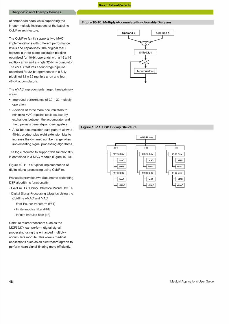
8/10/2019 Microcontroller Digital Blood Pressure Circuit
http://slidepdf.com/reader/full/microcontroller-digital-blood-pressure-circuit 48/88
8 Medical Applications User Guide
Diagnostic and Therapy Devices
f embedded code while supporting the
nteger multiply instructions of the baseline
ColdFire architecture.
he ColdFire family supports two MAC
mplementations with different performance
evels and capabilities. The original MAC
eatures a three-stage execution pipeline
ptimized for 16-bit operands with a 16 x 16
multiply array and a single 32-bit accumulator.
he eMAC features a four-stage pipeline
ptimized for 32-bit operands with a fully
ipelined 32 × 32 multiply array and four
8-bit accumulators.
he eMAC improvements target three primary
reas:
Improved performance of 32 × 32 multiply
operation
Addition of three more accumulators to
minimize MAC pipeline stalls caused by
exchanges between the accumulator and
the pipeline’s general-purpose registers
A 48-bit accumulation data path to allow a
40-bit product plus eight extension bits to
increase the dynamic number range when
implementing signal processing algorithms
he logic required to support this functionality
s contained in a MAC module (Figure 10-10).
igure 10-11 is a typical implementation of
igital signal processing using ColdFire.
reescale provides two documents describing
DSP algorithms functionality:
ColdFire DSP Library Reference Manual Rev 0.4
Digital Signal Processing Libraries Using the
ColdFire eMAC and MAC
- Fast-Fourier transform (FFT)
- Finite impulse filter (FIR)
- Infinite impulse filter (IIR)
ColdFire microprocessors such as theMCF5227x can perform digital signal
rocessing using the enhanced multiply-
ccumulate module. This allows medical
pplications such as an electrocardiograph to
erform heart signal filtering more efficiently.
Shift 0,1,-1
Figure 10-10: Multiply-Accumulate Functionality Diagram
Operand Y
X
Accumulator(s)
+/-
Operand X
Figure 10-11: DSP Library Structure
eMAC Library
FFT FIR IIR
FFT 16 Bits FIR 16 Bits IIR 16 Bits
MAC MAC MAC
eMAC eMAC eMAC
FFT 32 Bits FIR 32 Bits IIR 32 Bits
MAC MAC MAC
eMAC eMAC eMAC
Back to Table of Contents

8/10/2019 Microcontroller Digital Blood Pressure Circuit
http://slidepdf.com/reader/full/microcontroller-digital-blood-pressure-circuit 49/88
freescale.com/medical
Diagnostic and Therapy Devic
10.8
USB Connection
The USB connection allows the EGC to
communicate with other devices such as
hospital servers, remote monitoring systems
and computers. This can be implemented
using the USB On-the-Go module in the
MCF5227x. This module can be implemented
as a host or as a device. The MCF5227x has
internal PHY and the connection requires only
external pull-up or pull-down resistors.
10.9
Additional FreescaleTechnologies
This table describes additional
Freescale devices that can be used for
electrocardiograph and portable ECG
applications. To read the application notes
or for more information about any of these
devices, visit www.freescale.com.
Table 10-1. Additional Freescale Technologies for Electrocardiograph and Portable ECG Applications
Device Description Key features Applications Application Notes
MCF5225X One-stop-shopconnectivity
32-bitmicrocontrollers
External mini-FlexBus
interface
• Portable ECG
• Ventilation/Spirometry
• Hospital Admission Machine
AN3905: Writing First MQX Application
AN3906: Serial-to-Ethernet Bridge Using MCF51CN Family FreeRTOS
MCF5227X V2 microcontroller
with touch screen
LCD controller and USB • Portable ECG
• Debrillators
• Vital Signs Monitoring
• Ultrasound Control System
• Anesthesia Unit Monitor
AN3300: General Soldering Temperature Process
AN3298: Solder Joint and Package Peak Temperature
AN3631: Simplied Device Data Structures for ColdFire
AN3606: LCD Memory and Bus Bandwidth
AN3632: Touch Screen Controller on the MCF5227x
AN3631: Simplied Device Data Structures for the High-EndColdFire Family USB Modules
AN3750: Using a USB Device with ColdFire OTG Module
MCF522xx and a PC
MC34940 Proximity sensor Appliance control panels andtouch sensors
linear and rotational sliders
spill over flow sensingmeasurement
• Portable ECG
• Vital Signs Monitoring
• X-Ray User Interface
AN3747: Pad Layout Application Note
AN1985: Touch Panel Applications
AN3456: Generating a Supply Rail for the MC34940 andMC34941 in Low Voltage Systems
V B U S
D-
D+
G
Figure 10-12: Hardware Configuration in Host Mode
MCU with
USB module
D-
D+
Pull-down resistors
V DD
V B U S
D-
D+
G
Figure 10-13: Hardware Configuration in Device Mode
MCU with
USB module
D-
D+
Pull-up resistor USB power
V DD
Back to Table of Contents

8/10/2019 Microcontroller Digital Blood Pressure Circuit
http://slidepdf.com/reader/full/microcontroller-digital-blood-pressure-circuit 50/88
0 Medical Applications User Guide
Diagnostic and Therapy Devices
Defibrillators
1.1
Automated External Defibrillator (AED)
An automated external defibrillator (AED) is a portable device used to
estore normal heart rhythm to patients in cardiac arrest by delivering
n electrical shock to a patient through the chest wall. Cardiac arrest
s an abrupt loss of heart function. This occurs mainly because of
entricular fibrillation. This is a medical emergency.
entricular fibrillation is a condition where there is an uncoordinated
ontraction of the ventricles in the heart, making them tremble rather
han contract properly. The urgency of ventricular fibrillation requires
hat the heart must be defibrillated quickly; a victim’s chance of
urviving drops by 7 to 10 percent for every minute a normal heartbeat
s not restored.
An MCU calculates whether defibrillation is needed and a recorded
voice indicates whether to press the shock button on the AED. This
shock momentarily stuns the heart and stops all activity, giving the
heart an opportunity to resume beating effectively.
The charge is generated by high-voltage generation circuits from
energy stored in a capacitor bank in the control box. The capacitor
bank can hold up to 7 kV of electricity. The shock delivered from this
system can be anywhere from 30 to 400 joules.
Diagnostic and Therapy Devices
Back to Table of Contents

8/10/2019 Microcontroller Digital Blood Pressure Circuit
http://slidepdf.com/reader/full/microcontroller-digital-blood-pressure-circuit 51/88
freescale.com/medical
Diagnostic and Therapy Devic
11.2
Circuit for CapacitiveDischarge Defibrillators
In Figure 11-2, a step-up transformer (T2)
drives a half-wave rectifier and charges
the capacitor (C1). The voltage where C1
is charged is determined by a variableautotransformer (T1) in the primary circuit.
A series resistor (R1) limits the charging
current to protect the circuit components, and
determines the time constant Tao (T = R x C).
Five times the time constant for the circuit is
required to reach 99 percent of a full charge.
The time constant must be less than two
seconds to allow a complete charge in less
than ten seconds.
11.3
Circuit for Rectangular-Wave Defibrillators
In a rectangular-wave defibrillator, the
capacitor is discharged through the patient
by turning on a series of silicon-controlled
rectifiers (SCR). When sufficient energy has
been delivered to the patient, a shunt SCR
short circuits the capacitor and terminates
the pulse. This eliminates the long discharge
tail of the waveform. The output may be
controlled by varying either the voltage on the
capacitor or the duration of discharge. Figure
11-3 shows a general diagram of circuit
implementation.
Bipolar defibrillators are more efficient
because they need less energy while
providing the same results as unipolar
defibrillators. A bipolar defibrillator needs just
120 J to discharge. It has the same efficiency
as the 200 J of discharge used by a unipolar
defibrillator.
An ECG unit must be included in the
defibrillator’s system to monitor heart
activity and to control the moment when the
discharge can be applied to the patient. The
electrodes perform both functions, capturing
the patient’s ECG and delivering a high
current.
Figure 11-1: Defibrillators General Block Diagram
MCU Optional Peripherals Analog Sensors
MCU/MPU
USB
Signal
Conditioning
SyncronizationCircuit
Electrodes
DischargeCircuit
ECG Amplifier
Wireless
Comm
Power
Management
E l e c t r i c a l I s o l a t i o n
Display Keypad
Figure 11-2: Basic Circuit Diagram for a Capacitive Discharge Defibrillator
Figure 11-3: Block Diagram for a Rectangular-Wave Defibrillator
ChargeControl B
ChargeControl A
Monitor Circuit
Monitor Circuit
ChargeCircuit B
Capacitor Bank B
Capacitor Bank A
ChargeCircuit A
Back to Table of Contents

8/10/2019 Microcontroller Digital Blood Pressure Circuit
http://slidepdf.com/reader/full/microcontroller-digital-blood-pressure-circuit 52/88
2 Medical Applications User Guide
Diagnostic and Therapy Devices
1.4
Additional FreescaleTechnologies
able 11-1 describes additional Freescale
evices that can be used for defibrillator
pplications. To read the application notes,
r for more information about any of theseevices, visit freescale.com.
or power management, keypad and signal
onditioning (for speaker) and wireless
ommunication modules, see Chapter 3
ntroduction. For display (optionally with touch
creen) and USB communication modules,
ee Chapter 10.2 Electrocardiograph and
ortable ECG.
Figure 11-4: Unipolar Defibrillator Waveform
0
0
500
1000
1500
2000
2500
2 4 6 8 10
Time (ms)
1
V o l t s
12 14 16 18
Figure 11-5: Bipolar Defibrillator Waveform
0
0
500
1000
1500
2000
2500
5 10 15 20 25
Time (ms)
1
V o l t s
30 35 40 45
Table 11-1. Additional Freescale Devices For Defibrillator Applications
Device Description Key features Applications Application Notes
MC3467x V3 ColdFiremicroprocessor
LCD driver Ethernet
USB CAN
• Debrillators
• Vital Signs Monitoring Hospital
• Admission Machine
• Control System
• Anesthesia Unit
• Monitor
• Powered Patient Bed
AN3324: Hardware Congurations for the MCF532x
AN3408: Building a Sample CGI Application
AN3757: Using MCF5329EVB NAND Flash to Host uClinux RootFile System
Back to Table of Contents
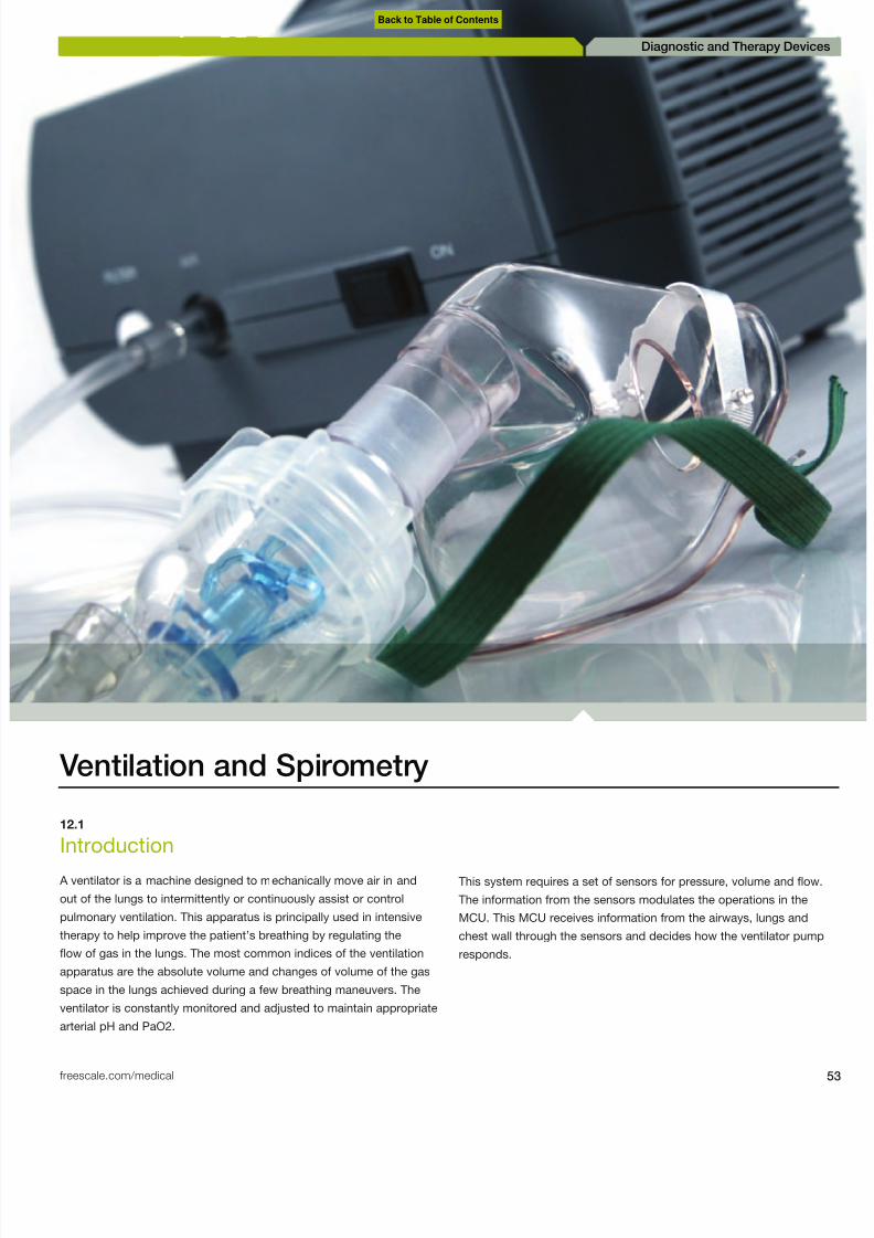
8/10/2019 Microcontroller Digital Blood Pressure Circuit
http://slidepdf.com/reader/full/microcontroller-digital-blood-pressure-circuit 53/88

8/10/2019 Microcontroller Digital Blood Pressure Circuit
http://slidepdf.com/reader/full/microcontroller-digital-blood-pressure-circuit 54/88
4 Medical Applications User Guide
Diagnostic and Therapy Devices
2.2
System Sensors
he signal that shows lung volume is a
ifferential signal, but this is not the signal
measured directly from the lungs. To get
his signal, it is necessary to transduce the
ressure to voltage. This is done by using aneumotachometer that contains a pressure
ensor.
reescale provides a variety of sensors that
se integrated circuits for signal conditioning.
his is an advantage because external
omponents are not necessary. However, it
s necessary to check the resolution of the
ensor and the ADC. If the resolution of the
ADC is greater than the sensor, amplifying
he signal is recommended. Some sensors
rovide differential outputs for when it is
ecessary to pass the signal through an
nstrument amplifier. The sensor used is a
ifferential pressure sensor that can accept
wo sources of pressure simultaneously. The
utput is proportional to the difference of the
wo sources. It is important to mention that
he normal pipeline gas source of a hospital
s 50 PSI, a measurement that can be taken
y Freescale’s pressure sensors. Freescale
ressure sensors include MPX2301DT1,
MPXC2012DT1, MPXx5050 and MPXx5050.
2.3
Spirometer
pirometers measure static pulmonary
olumes, except the functional residual
apacity (FRC) and total pulmonary capacity
TPC). The measurement is done after a
maximum inspiration that requires the patient
o expel the entire volume of air that he or she
an. The results are interpreted and compared
with the values for age, height, sex and race
f the patient. Due to variations among normal
ndividuals, normal values can fall between 80
o 120 percent of the expected volume. Figure
2-2 illustrates how to configure a spirometer
sing a pressure sensor. The next two figures
bserve the different volumes of lungs.
Figure 12-1: Ventilation/Respiration General Block Diagram
Keypad
PWR
PWFSensor
MCU/MPU
Nebulizer Accumulator/
Compressor Blender
PWR
Alarm
AIR O2
PressureSensor
VolumeSensor
FlowSensor
Power Management
AMP
USB
MCU Optional Peripherals Analog Sensors
Display
Figure 12-2: Spirometer
MPX2300DT1
MPX2301DT1
MPXC2011DT1
MPXC2012DT
MPX5050
MPX2050
Optional Instrument Amplifier
Back to Table of Contents

8/10/2019 Microcontroller Digital Blood Pressure Circuit
http://slidepdf.com/reader/full/microcontroller-digital-blood-pressure-circuit 55/88
freescale.com/medical
Diagnostic and Therapy Devic
Lung volume measurements include:
• Tidal volume (TV)—The amount of gas
inspired or expired with each breath (500 ml)
• Inspiratory reserve volume (IRV)—Maximum
amount of additional air that can be inspired
at the end of a normal inspiration (2500 ml)
• Expiratory reserve volume (ERV)—The
maximum volume of additional air that can
be expired at the end of a normal expiration
(1500 ml)
• Residual volume (RV)—The volume of air
remaining in the lungs after a maximum
expiration (1500 ml)
These measurements can be used in
the following equations to express lung
capacities:
• Total lung capacity (TLC)
TLC=RV+IRV+TV+ERV (6000 ml)
• Vital capacity (VC)
VC=IRV+TV+ERV=TLC-RV (4500 ml)
• Functional residual capacity (FRC)
FRC=RV+ERV (3000 ml)
• Inspiratory capacity (IC)
IC=TV+IRV (3000 ml)
12.4
Graphic LCD MPU
Freescale offers the following devices that
generate graphics. These devices can be
used to show lung volume.
• MCF5227X V2 microcontroller with touch
screen, LCD controller, and USB: The
32-bit ColdFire microprocessor portfolio
is expanding with low system cost LCD
solutions, giving control, flexibility and
performance options for human machine
interface and industrial control applications
• MCF532X V3 ColdFire microprocessor with
LCD driver, Ethernet, USB and CAN: By
introducing the integrated LCD controller on
a 68K and ColdFire device, the MCF532x
family of microprocessors addresses the
growing demand for human interfaces on
machine and industrial control applications
while maintaining a rich level of connectivity
and security integration.
For more information, see the application note
titled Understanding LCD Memory and Bus
Bandwidth Requirements (document AN3606)
available at freescale.com.
12.5
Alarm System
An important part of this application is an
alarm that can indicate different patient
parameters such as exhaled volume or airway
pressure. The ventilation system must be able
to detect whether a breath has been taken.
The MCU measures changes in aspiratory
flow and pressure by using sensors. If no
inspiration is detected within a certain pe
of time, the monitor sounds an alarm. The
conditions to be programmed depend on
system. PWM cycles can be programmed
sound the alarms. Sometimes, the ventila
system uses different alarms for different
situations. To see the alarm circuit, refer t
Chapter 3, Telehealth Systems.
Figure 12-3: Normal Spirometer
1
00 1 2 3 4
2
3
4
5
6
7
8
Volume (L)
Time (sec)
FEV 1
F F
F
FVC
Figure 12-4: Normal Lung Volume
0
Time
FRC
TLC
ERV
V T
IRV
RV
IC
VC
Back to Table of Contents

8/10/2019 Microcontroller Digital Blood Pressure Circuit
http://slidepdf.com/reader/full/microcontroller-digital-blood-pressure-circuit 56/88
6 Medical Applications User Guide
Diagnostic and Therapy Devices
2.6
Air and Oxygen Blenderand Mix Control
he air and oxygen blender provides a precise
xygen concentration by mixing air and
xygen. The concentration may be adjusted
o any value from controlled air to 100 percentxygen. Internally, a proportioning valve mixes
he incoming air and oxygen as the oxygen
ercentage dial is adjusted. Variation in line
ressure, flow or pressure requirements for
ny attached device will not affect the oxygen
oncentration.
he preparation of an air and oxygen blender
enerally consists of attaching a 50 PSI air
nd oxygen source to the device. After the
ource gases are attached, inlet pressures
may be checked on some blenders byhecking the pressure-attached pressure
auge. After the inlet gases are attached and
he air and oxygen blender is well secured
o a stand or wall mount, it is ready for use.
he MCU uses a PWM to control the blender
lectro valves through a motor control design.
arly ventilator designs relied on mechanical
lenders to provide premixed gas to a single
ow control valve. With the availability of
igh-quality flow sensors and processing
apabilities, accurate mixing becomesossible by using separate flow valves for
ir and oxygen. Because air already contains
bout 21 percent oxygen, the total flow
ontrol command between the oxygen and air
alve is divided ratiometrically. For extreme
mix settings, the valve that supplies the minor
ow at low total flow requirements may fall
elow the resolution limits that either flow
elivery or measurement can provide. An
ccurate delivered mix depends on accurate
ow delivery, but if accurate and reliable
xygen sensors are used, improved mix
ccuracy may be possible by feeding back a
measured concentration for mix correction.
hen, if the patient needs more pressure, the
MCU activates the compressor.
o learn more, see the article Automatic
Ventilation Control in the Freescale design
magazine Beyond Bits IV .
Figure 12-5: Graphic LCD Product Map
R
E S O L U T I O N
PIN COUNT - PACKAGE
QVGA
WQVGA
ColdFire
112 pin
ColdFire
VGA
196 pin
ColdFire
ColdFire
SVGA
ColdFire
144 pin
ColdFire
MCU
196 pin
MCF5227x
MCF5227x
MPUGraphic
176 pin
MCF5227x
256 pin
MCF5227x
Future Product 3V
Figure 12-6: MC56F8006/2 Block Diagram
Three AnalogComparators
Two 12-bit ADCs
Two 16-bitTimers
Two 2x-16x
Wideband PGAs
COP
RTC
One 16-bitPeriodic Interval
Timer
Flash/RAMPower
Supervisor
ProgrammableDelay Block
(PDB)
SPI Voltage
Regulators6-Output PWM
High-Speed
SCI
Interrupt
Controller I2C
System Integration
Module (SIM)
56800 Core/32MIPS
System Clock Control
(COSC, ROSC, PLL)
JTAG/EOnCE™
Memory Options
2 KB
SRAM
16 KB
Flash
2 KB
SRAM
12 KB
Flash
Back to Table of Contents

8/10/2019 Microcontroller Digital Blood Pressure Circuit
http://slidepdf.com/reader/full/microcontroller-digital-blood-pressure-circuit 57/88
freescale.com/medical
Diagnostic and Therapy Devic
MCF5225X: One-Stop-
Shop Connectivity in 32-bit
Microcontrollers
Key features of this MCU include:
• V2 ColdFire core with 66 MHz and 80 MHz
options
• Complimentary Freescale MQX software
solutions
• Connectivity—USB 2.0 full-speed host/
device/OTG controller, FlexCAN controller
and 10/100 Ethernet controller
• External mini-FlexBus interface
• Cryptographic accelerator unit
• Up to 512 KB of flash memory
• Up to 64 KB SRAM
MPX230xDT1: High Volume Pressure
Sensor
Key features of this sensor include:
• Cost effective
• Integrated temperature compensation and
calibration
• Ratiometric to supply voltage
• Polysulfone case material (ISO 10993)
• Provided in tape and reel
MPXx5050: –50 to 0 kPa and 0 to
50 kPa Integrated Silicon Pressure
Sensor, Temperature Compensated
and Calibrated
Key features
• 2.5% maximum error over 0° to +85°C
• Ideally suited for microprocessor or
microcontroller-based systems
• Temperature compensated from over -40°C
to +125°C
• Patented silicon shear stress strain gauge
MPXx2050: 50 kPa Pressure Sensor
Key features of this sensor include:
• Temperature compensated over 0°C to +85°C
• Silicon shear stress strain gauge
• Available in rails or tape-in-reel shipping
options
• Ratiometric to supply voltage
• Differential and gauge options
• ±0.25% linearity
Figure 12-8: MCF5225x Block Diagram
USBOTG
10/100
FEC
CAN
2-ch.
PIT
8-ch.
PWM
E M A C
D M A
BDM PLL 32 kHzOsc
GPI/O JTAG
4-ch.,32-bitTimer
4-ch.,16-bitTimer
RTC
4-ch.
DMA
I2C
QSPI
8-ch.,
12-bit ADC
2X
INTC
System
Integration
V2 ColdFire
Core
UART
UART
UART
CAU/
RNG
Mini
Bus
Memory Options
Memory Options
512 KB
Flash
64 KB
SRAM
256 KB
Flash
64 KB
SRAM
256 KB
Flash
32 KB
SRAM
Figure 12-7: Blender Configuration
PWR
MCU/MPU
Accumulator/ Compressor
Blender
PWR
AIR O2
Table 12-1. MPXx2050 Packaging Information
Device Type Packing Options Case
MPX2050D Differential 344
MPC2050DP Differential, Dual Port 423 A
MPX2050GP Gauge 344B
MPX2050GSX Gauge Axial PC Mount 344F
Back to Table of Contents

8/10/2019 Microcontroller Digital Blood Pressure Circuit
http://slidepdf.com/reader/full/microcontroller-digital-blood-pressure-circuit 58/88
8 Medical Applications User Guide
Diagnostic and Therapy Devices
2.7
Additional FreescaleTechnologies
his table describes additional Freescale
evices that can be used for ventilation
nd spirometry applications. To read the
pplication notes, or for more information
bout any of these devices, visit
reescale.com.
For power management, keypad, signal
conditioning and wireless communication
modules, see Chapter 3 Introduction.
Table 12-2. Additional Freescale Technologies For Ventilation and Spirometry Applications
Device Description Key features Applications Application Notes
MCF5221X 32-bit microcontroller USB On-The-Go • Ventilation/Spirometry
• X-Ray Control System
• Anesthesia Unit Monitor
AN1984: Handling Freescale Pressure Sensors
AN3150: Soldering Recommendations for Pressure SensorDevices
MPX2300DT1 Compensatedpressure sensormedical grade
Patented piezoresistive
strain gauge implant,temperature compensationand calibration all integratedon a single, monolithicsensor die
• Blood Pressure Monitors
• Ventilation/Spirometry
• Sensors
• Anesthesia Unit Monitor
AN1984: Handling Freescale Pressure Sensors
AN3150: Soldering Recommendations for Pressure SensorDevices
MPXx5050 Pressure sensor -50 to 0 kPa and 0 to 50 kPa
Temperature compensatedand calibrated
• Blood Pressure Monitors
• Ventilation/Spirometry
• Sensors
• Anesthesia Unit Monitor
Beyond Bits IV: Blood Pressure Monitors
Beyond Bits IV: Automatic Ventilation Control
MPXx2050 50 kPa pressure
sensor
Silicon shear stress strain
gauge
• Blood Pressure Monitors
• Ventilation /Spirometry• Sensors
• Anesthesia Unit Monitor
AN1315: An Evaluation System Interfacing the MPX2000 Series
AN1316: Frequency Output Conversion for MPX2000 Series AN1082: Simple Design for a 4–20 mA Transmitter Interface
AN1097: Calibration-Free Pressure Sensor System
AN1100: Analog to Digital Converter Resolution Extension Usinga Pressure Sensor
Back to Table of Contents

8/10/2019 Microcontroller Digital Blood Pressure Circuit
http://slidepdf.com/reader/full/microcontroller-digital-blood-pressure-circuit 59/88
freescale.com/medical
Diagnostic and Therapy Devic
Anesthesia Unit Monitor
13.1
Introduction An anesthesia unit monitor is a machine that administers anesthesia to
patients by one of two ways: intravenous or inhaled gas anesthesia.
It exchanges respiratory gases and administers anesthetic gases.
It maintains a balance of gases through the respiratory and
cardiovascular system.
Diagnostic and Therapy Devic
Back to Table of Contents

8/10/2019 Microcontroller Digital Blood Pressure Circuit
http://slidepdf.com/reader/full/microcontroller-digital-blood-pressure-circuit 60/88

8/10/2019 Microcontroller Digital Blood Pressure Circuit
http://slidepdf.com/reader/full/microcontroller-digital-blood-pressure-circuit 61/88
freescale.com/medical
Diagnostic and Therapy Devic
Finally, the patient breathes the anesthesia
mixed through the mass flow controller.
The Freescale MCF520X and the MCF532X
microcontrollers are recommended for this
application.
MCF520X: Integrated V2 ColdFire
External Memory and EthernetMicroprocessor
Key features of this processor include:
• High-performance V2 ColdFire core,
166 MHz
• eMAC (32 x 32) module, hardware divided
Integrated peripherals
• Flexible 16-bit DDR/32-bit SDR SDRAM
memory controller
• Four channels, 32-bit timers with DMA
support• 16 channels, DMA controller
• 16-bit DDR/32-bit SDR SDRAM controller
• 50 general-purpose I/O
MCF532X: V3 ColdFire
Microprocessor with LCD driver,
Ethernet, USB and CAN
Key features of this processor include:
• V3 ColdFire core delivering up to 211
(Dhrystone 2.1) MIPS at 240 MHz
• 32 KB RAM
• 16 KB I/D-cache
• Enhanced MAC module, manages DSP-like
instructions
Integrated peripherals
• USB Host/USB OTG
• 10/100 Fast Ethernet Controller (FEC)
• QSPI
• Serial Synchronous Interface (SSI)
• PWM—4 channels
• DMA—16 channels• 16-bit DDR/32-bit SDR SDRAM controller
• Integrated SVGA LCD controller
Figure 13-3: MCF520x Family
V2 ColdFireCore
MAC
16K SRAM8 KB I/D Cache
SystemBus
Controller
DDR/SDRSDRAM
Controller and ChipSelects
BDM PLL GPIO JTAG
4-ch., 32-bitTimer
I2C 16-ch. DMA UART
QSPI UART UART
Debugging/Interfaces Peripherals RAM Core Plus Features
10/100
FEC DMA
Figure 13-4: MCF532x Family Block Diagram
32 KB SRAM16 KB Unified Cache
BDM PLL GPIO JTAG
SVGA LCD
Controller
4-ch., 32-bit
Timer USB h/d/OTG UART
16-ch. DMA Crypto
CAN
Optional Additional
Modules
4-ch. PWM USB Host UART
SSI I2C QSPI UART
DDR/SDR SDRAM Controller
and Chip Selects
V3 ColdFire
CoreeMAC
System Bus
Controller
10/100
FECDMA
Debugging Interface Peripherals Flash/ROM RAM Core Plus Feature
Back to Table of Contents

8/10/2019 Microcontroller Digital Blood Pressure Circuit
http://slidepdf.com/reader/full/microcontroller-digital-blood-pressure-circuit 62/88
2 Medical Applications User Guide
Diagnostic and Therapy Devices
Vital Signs
4.1
ntroduction
A vital sign monitor is a multi-parameter device that measures blood
ressure, temperature, oxygen saturation and heart electrical activity to
ive a clear view of patient information.
his application constantly monitors the measurements from the ECG,
ulse oximetry, blood pressure and temperature of the patient. For this
pplication, Freescale offers medical solutions that use our product
xpertise in microcontrollers, sensors, analog and wireless technology
or home portable medical devices, diagnostic and therapy devices
nd medical imaging devices. Freescale is dedicated to helping
atients live a better life by driving innovation and enabling medical
evice manufacturers to leverage the latest available technology.
Diagnostic and Therapy Devices
Back to Table of Contents

8/10/2019 Microcontroller Digital Blood Pressure Circuit
http://slidepdf.com/reader/full/microcontroller-digital-blood-pressure-circuit 63/88
freescale.com/medical
Diagnostic and Therapy Devic
14.2
Measuring Temperature
The Freescale S08QG family includes
a temperature sensor whose output is
connected to one of the ADC analog channel
inputs. The approximate transfer function of
the temperature sensor can be expressed by
this equation:
Temp = 25 – ((VTEMP – VTEMP25)/m)
For more information about the temperature
sensor, see the datasheet titled MC9S08QG8/
QG4 Device Datasheet, available on the
Freescale website at www.freescale.com.
Features of the ADC module include:
• Linear successive approximation algorithm
with a 10-bit resolution
• Output formatted in 10- or 8-bit right-
justified format
• Single or continuous conversion (automatic
return to idle after a single conversion)
• Configurable sample time, conversion
speed and power
• Conversion complete flag and interrupt
• Input clock selectable from up to four
sources
• Operation in Wait or Stop3 modes for low
noise operation
For more information about how to send
the ADC values to the main MCU, see the
application note titled Analog-to-Digital
Converter on an IIC Bus Using MC9S08QG8
(document AN3048), available on the
Freescale website at www.freescale.com.
14.3
ECG MonitoringFor more information about designing
ECG, pulse oximetry and blood pressure
applications, see the relevant chapters.
14.4
Pulse Oximetry Monitoring A pulse oximeter is a device that measures
the amount of oxygen saturation in the blood.
This parameter is useful for patients with
metabolic disorders like respiratory acidosis,
alcalosis, chronic obstructive pulmonary
disease (COPD), and restrictive pulmonary
disease.
Figure 14-1: Vital Signs Monitoring General Block Diagram
Receptor Diode
Red and
Infrared LEDs
Finger
Clamp
Amp
12 Leads Electrical
Protection and Mux
Signal
Conditioning
Signal
Conditioning
Switching Module
MCU/MPU
Display withTouch Screen
Keypad Power Management
USB
Wireless
Comm
Arm
Valve
Pressure
Sensor
Motor
Control
Pump
Motor
TempSensor
Sensor
Amp
ADC
PWM
SPI/I2C
MCU Optional Peripherals Analog Sensors
Figure 14-2: General Overview of Temperature Measurement
AD26
ADC Channel
Principal
MCU/MPUI2C
Figure 14-3: ECG Monitoring General Overview
AD26
ADC Channel
Principal
MCU/MPUI2C
Back to Table of Contents

8/10/2019 Microcontroller Digital Blood Pressure Circuit
http://slidepdf.com/reader/full/microcontroller-digital-blood-pressure-circuit 64/88
4 Medical Applications User Guide
Diagnostic and Therapy Devices
4.5
Blood PressureMonitoring
A blood pressure monitor is a device that
measures the systolic and diastolic blood
ressure by inflating a cuff until it equals
he systolic pressure and then deflates untilhe diastolic pressure is bypassed. Other
arameters can be measured like mean
rterial pressure and heart rate.
4.6
Motor Control withFreescale Devices
he Freescale MPC17C724 is a 0.4 amp dual
H-bridge motor driver IC with the following
eatures:
Built in 2-channel H-bridge driver
Provides four driving modes
• Forward
• Reverse
• Break
• High impedance
Direct interface to the MCU
Low ON-resistance, RDS(ON) = 1.0 Ω
(typical)
PWM control frequency 200 kHz (max)
o design Keypad, Power Management,
Wireless Communications, and USB
modules, see Chapter 3 Telehealth Systems
ntroduction. For a display with a touch screen
ee Chapter 10.2, Electrocardiograph and
ortable ECG.
Figure 14-4: Signal Conditioning to ECG Monitoring
Right Hand
To MCU ADC input
Left Hand
Right Leg Left Leg
AnalogFrond End
Electrodes
Multiplexer
and Isolator
Instrumentation
Amplifier
Band Pass
Filter
Signal
Conditioning
Figure 14-5: General Overview of Pulse Oximetry Monitoring
Red and
Infrared LEDs
To Principal
MCU/MPU
Receptor Diode
Switching Module
Finger
Clamp
Figure 14-6: Signal Conditioning for Pulse Oximetry Monitoring
3 MΩ
3 pF
100 kΩ
1 kΩ
ExtractedDC
Component
Back to Table of Contents

8/10/2019 Microcontroller Digital Blood Pressure Circuit
http://slidepdf.com/reader/full/microcontroller-digital-blood-pressure-circuit 65/88

8/10/2019 Microcontroller Digital Blood Pressure Circuit
http://slidepdf.com/reader/full/microcontroller-digital-blood-pressure-circuit 66/88
6 Medical Applications User Guide
Diagnostic and Therapy Devices
ntelligent Hospitals
5.1
ntroduction
he connected hospital is the wave of the future. With the increasing
cceptance of technology in the medical market, administrators are
pen to infusing that technology into hospitals to help increase the
uality of service.
Automated hospital admittance kiosks, tracking devices/bracelets
nd automatic inventory control are just some of the applications
he medical team is working on at Freescale. By leveraging our
trengths in ColdFire and ARM® (i.MX) embedded processing, wireless
ommunications and PowerQUICC network processing, Freescale
trives to put the intelligence in hospitals.
Intelligent Hospitals
Back to Table of Contents

8/10/2019 Microcontroller Digital Blood Pressure Circuit
http://slidepdf.com/reader/full/microcontroller-digital-blood-pressure-circuit 67/88
freescale.com/medical
Intelligent Hospit
15.2
Hospital AdmissionMachine
A hospital admission machine helps patients
and doctors increase the efficiency of a
hospital through automating procedures
which usually take time from the nurses andadministrative employees.
These solutions need to integrate a broad
range of medical devices in order to perform
necessary functions for the physician and
increase the range of early diagnosis/
symptoms and signs that can alert medical
staff to acute complications in patients being
monitored at home (using portable mode) or in
specific strategic places such as malls (using
medical kiosks).
State-of-the-art technology—including low
power, analog integrated microcontrollers
such as Freescale’s 8-bit 9S08MM and 32-bit
MCF51MM—allow the designer to achieve
portability for touch sensing and medical-
grade communication (following Continua
Health Alliance™ guidelines) with libraries
that are downloadable from the Freescale
webpage, http://www.freescale.com/medical.
These elements enable solutions focused on
preventive medicine, which ultimately reduce
patients’ acute complications and costsrelated to their treatment. This can help health
institutions redirect money used for treatment
toward prevention, and can help insurance
companies cut costs.
The hospital kiosk includes a touch-sensing
interface that allows the user to navigate the
machine’s interface. This flat surface makes
the machine easier to disinfect after each user.
It is more difficult to disinfect a machine with
mechanical buttons that can hold pathogens
such as bacteria and viruses in the edge ofthe buttons.
The kiosk includes a magnetic card reader
used to identify the patient and to keep a
record of the patient’s abbreviated e-chart.
The e-chart contains the following data:
• ID fields: first name, last name, birth date,
gender, contact information
• Family medical history: Cancer,
cardiovascular disease, chronic
degenerative diseases such as arthritis,
kidney disease, asthma, neurological
disorders, etc.
• Personal medical history: Medicines,
surgeries, diseases, etc.
• Non-pathological personal history: Blood
type, alcohol and tobacco use, drug abuse,
allergies, etc.)
Once the patient is identified through the
magnetic card, the machine can take the
following measurements:
• Capillary blood glucose levels
• Systolic, diastolic and mean arterial
pressure
• Weight, height and body mass index
• Temperature
• Heart rate
• EKG DI
• Oxygen saturation level (SaO2)
• Maximum expiratory and inspiratory flow
peak
• Inspiratory and expiratory lung volume
After that a test result paper is printed an
a remote database is updated with these
readings. If the kiosk detects a critical
problem, it sends the report to a mobile
device that could report the finding to a
physician or healthcare provider.
A step-by-step video shows how to perfo
these tests so that the user can perform
the tests without help from a healthcare
professional. With language support in
English, Spanish and Japanese, the user
sees and hears how to perform these test
As users become more familiar with the
device, they may pay less attention to the
instructions. This is why we also offer the
patient monitor interface.
For an easy-to-use mode, the main core o
the kiosk can be separated. This creates
USB-powered portable device for home u
or use at remote facilities when a physicia
not nearby.
Figure 15-1: Hospital Admission Machine General Block Diagram
To ContinuaHealth Alliance
Host in PC
ZigBee BoardMC13213
i.MX 35/51 Bluetooth®
Board
ECGMC56F8006
Graphic DisplayTouch Sensing
Glucometer
TWR-MMor
MCF51JM
USB
SCI
ADC
ADC
ADC
ADC
12C ADC
Communication Board
Analog Front End Boards Middle-End Mode
Display
High-End Mode
Wireless Communication Boards
Height, Weight,Thermometer
Blood PressureMPX3V5050
Pulse Oximeter MPC17C724
Spyrometer MPXV7025
Back to Table of Contents

8/10/2019 Microcontroller Digital Blood Pressure Circuit
http://slidepdf.com/reader/full/microcontroller-digital-blood-pressure-circuit 68/88
8 Medical Applications User Guide
Intelligent Hospitals
he following sections describe the parts of
he system (some of them have already been
escribed in previous chapters):
Weight scale
Height ultrasonic sensor
Thermometer
Blood pressure monitor (systolic, diastolic,
mean arterial pressure)
Heart rate monitor
1-lead EKG (DI)
Pulse oximeter
Blood glucose meter
Spirometer (air flow and lung volume )
5.3
Patient Height and Weight
he patient’s height is taken by an ultrasonic
ensor which measures the distance between
he head and the sensor. An MCU takes the
ata produced by the transducer and uses an
quation to calculate the distance between
he sensor and the head, then calculates the
ifference between this distance and the total
istance to the floor.
he patient’s weight is taken by a pressure
ensor. This operation is explained in the
Ventilation and Respiration” application
rticle. In general, after signal conditioning
roduces a voltage, this voltage is passed
hrough the ADC of a microcontroller to
e processed and then could be passed
y RS-232 or USB to the principal
microprocessor. The general block diagram
hows that the weight of the patient is passed
hrough RS-232, although you can transmit
y USB (optional). If you use RS-232, it is
ecessary to add a MAX232 device according
o the protocol (see Figure 15-4).
5.4
Patient Interfacehe patient has an interface to communicate
with the admission machine. This interface is
omposed of a touch screen display, LEDs
nd a buzzer to warn if a decision must be
made or if a process is finished. This module
s developed with a secondary microcontroller,
which could be the Freescale S08QE.
Figure 15-4: Configuration to Measure Patient Weight
MAX232 ADC
SCIOptional instrumentamplifier
Freescale Pressure SensorsMPXx5004
MPXx5004MPXC2011DT1
MPXx12
MPXx5010MPXx2010
MPXV 2053GVO
MPXV5100
Figure 15-3: Measuring Patient Height
Transmitter Receptor
HeightUltrasonic
Sensor
D=1/2Vt
Figure 15-2: Portable Monitoring System
Back to Table of Contents

8/10/2019 Microcontroller Digital Blood Pressure Circuit
http://slidepdf.com/reader/full/microcontroller-digital-blood-pressure-circuit 69/88
freescale.com/medical
Intelligent Hospit
15.5
Communication Interfaces
USB Power Switch
When the patient arrives at the hospital,
special devices take the principal vital signs of
height, weight and heart rate. These devices
are connected to the principal system. Whenthe devices are connected by USB, this turns
on the devices and the principal MPU starts
the communication as host.
The USB port is implemented in a regulator
(MC33730) that provides 5V @ 2A out.
However, the devices only support 500 mA.
Therefore it is necessary to add a 500 mA
fuse to regulate the current. The USB module
of the principal MPU is configured as a host
that can turn on the external devices and start
communication between the external devicesand the principal MPU.
The microprocessors recommended for
this application have two or more hosts
integrated; therefore, you can use more than
one USB device without using a hub. To see
recommended microprocessors, go to www.
freescale.com/medical.
Serial Communication Interface
SCI (Serial Communications Interface) is an
asynchronous serial communications bus
that an MCU uses to communicate with other
MCUs or external devices using SCI. Two
signal lines are used with SCI: TXD (transmit)
and RXD (receive). The two-wire SCI bus
operates in full-duplex mode (transmitting and
receiving at the same time). SCI uses either
an 8- or 9-bit data format, with data sent
using NRZ (non-return-to-zero) encoding. The
SCI bus may also be set up as a single wire
interface, using the TXD pin to both send and
receive data. The SCI is a generic controller
which allows the integration of RS232, RS422and RS485 serial transceivers.
Figure 15-5: Analog Configuration for LEDs and Buzzer
120Ω
1kΩ330Ω
MCUMCU
o.1 uF
A
K
Figure 15-6: USB General Configuration
IN
5V
ENB OUT
FLAG
USBHOST_VBUS_EN
USBHOST_VBUS_OC
Power distribution
chip or circuit
USB A or mini-A
receptacle
MCF532x
1–VBUS
Optional ESD circuit
Optional ferrite beadPlace resistors close
to the processor
2–D–
3–D+
4–GNDFB
33Ω
USB_DM
15 kΩ
33Ω
USB_DP
15 kΩ
Figure 15-7: USB Port Connections
Power
Source MC33730
Back to Table of Contents

8/10/2019 Microcontroller Digital Blood Pressure Circuit
http://slidepdf.com/reader/full/microcontroller-digital-blood-pressure-circuit 70/88
0 Medical Applications User Guide
Intelligent Hospitals
Data can be sent as 8- or 9-bit words, least
ignificant bit (LSB). A START bit marks the
eginning of the frame. The start bit is active
ow. The figure above shows a framed 8-bit
ata word. The data word follows the start
it. A parity bit may follow the data word after
he most significant bit (MSB) depending on
he protocol used. A mark parity bit (always
et high), a space parity bit (always set low)
r an even/odd parity bit may be used. The
ven parity bit will be a one if the number of
nes/zeros is even or a zero if there is an odd
umber. The odd parity bit will be high if there
re an odd number of ones/zeros in the data
eld. A stop bit will normally follow the data
eld. The stop bit is used to bring the signal
ests at logic high following the end of the
rame, so when the next start bit arrives it will
ring the bus from high to low. Idle characters
re sent as all ones with no start or stop bits.reescale MCUs provide 13-bit baud. The SCI
modules can operate in low power modes.
Ethernet PHY (100 Mbps)
o connect the MCU to the internet or
o control the system remotely, you can
mplement an Ethernet communication
nterface. This needs coupling impedance for
he RJ-45 connection.
5.6
Backlight InverterA backlight is a form of illumination used
n liquid crystal displays (LCDs). Backlights
uminate the LCD from the side or back of
he display panel, unlike front lights, which are
laced in front of the LCD.
16
15
14
13
12
11
10
9
Figure 15-9: Serial Communication Interface General Configuration
+
+
+
+
+
MAX 232
ADC
SCI
Rx
Tx
Rx
Tx
1
2
3
4
5
6
7
8
16
15
14
13
12
11
10
9
+
+
+
+
+
MAX 232
MPU/
SCI
1
2
3
4
5
6
7
8
Figure 15-10: Ethernet Interface Circuitry
49.9Ω49.9Ω
49.9Ω
0.1 uF
3.3V
49.9Ω
75Ω
Figure 15-8: SCI Tram
0 1 0 0 1 1 0 1 1 1
Back to Table of Contents

8/10/2019 Microcontroller Digital Blood Pressure Circuit
http://slidepdf.com/reader/full/microcontroller-digital-blood-pressure-circuit 71/88

8/10/2019 Microcontroller Digital Blood Pressure Circuit
http://slidepdf.com/reader/full/microcontroller-digital-blood-pressure-circuit 72/88
2 Medical Applications User Guide
Intelligent Hospitals
5.8
Additional FreescaleTechnologies
able 12-1 describes additional Freescale
evices that can be used for hospital
dmission machine applications, and the
pplication notes and datasheets that explainmore. To read the application notes, or for
more information about any of these devices,
isit www.freescale.com.
or wireless communication, power
management, keypad and speaker
mplementation modules, see the “Telehealth
ystems” application article beginning on
age 6.
Table 12-1: Additional Freescale Technologies for Hospital Admission Machine Applications
Device Description Key Features Applications Application Notes
MPXx5004 Pressure sensor 0 to 3.92 kPa
Temperature compensatedand calibrated
Digital Weight Datasheets available at:
http://www.freescale.com/webapp/sps/site/prod_summary.jsp?code=MPXx5004
MPXC2011DT1 Compensatedpressure sensor,medical grade
Polysulfone (Mindel S-1000)
Case material (medical,Class V)
Digital Weight AN1984: Handling Freescale Pressure Sensors
AN3150: Soldering Recommendations for Pressure SensorDevices
MPXx12 Pressure sensor 10 kPa Digital Weight Datasheet: http://www.freescale.com/les/sensors/doc/data_sheet/MPX12.pdf
MPXx5010 Pressure sensor 0 to 10 kPaTemperature compensatedand calibrated
Digital Weight AN3728: Media Compatibility for IPS PRT Pressure Sensors AN1636: Implementing Auto Zero for Integrated PressureSensors
AN1646: Noise Considerations for Integrated Pressure Sensors
AN1326: Barometric Pressure Measurement
AN1322: Applying Sensors to Bar Graph Pressure Gauges
AN1318: Interfacing Pressure Sensors to Microcomputers
AN1668: Washing Appliance Sensor Selection
AN1586: Designing a Homemade Digital Output for Analog Voltage Output Sensors
MPXx2010 Pressure sensor 10 kPa Digital Weight AN1516: Liquid Level Control Using a Pressure Sensor
AN936: Mounting Techniques, Lead Forming, and Testing
AN1082: Simple Design for a 4-20 mA Transmitter Interface
AN1097: Calibration-Free Pressure Sensor System
AN1950: Water Level Monitoring
AN4010: Low-Pressure Sensing Using MPX2010
MPXV5100 Integrated pressure
sensor
Available in gauge and
upon request, absolute anddifferential
Digital Weight AN1660: Compound Coefcient Pressure Sensor PSPICE
Models AN1304: Integrated Sensor Simplies Bar Graph PressureGauge
Back to Table of Contents

8/10/2019 Microcontroller Digital Blood Pressure Circuit
http://slidepdf.com/reader/full/microcontroller-digital-blood-pressure-circuit 73/88
freescale.com/medical
Intelligent Hospit
Powered Patient Bed
16.1
Introduction A simple hospital bed has evolved into a highly networked appliance
that integrates sophisticated processors to monitor patient status
and control the bed’s power-assisted functions. This improves patient
comfort and makes it easier for healthcare professionals to maneuver
the beds.
Intelligent Hospit
Back to Table of Contents

8/10/2019 Microcontroller Digital Blood Pressure Circuit
http://slidepdf.com/reader/full/microcontroller-digital-blood-pressure-circuit 74/88
4 Medical Applications User Guide
Intelligent Hospitals
6.2
Using Motors for PatientPositioning
ressure ulcers or decubitus ulcers (bedsores)
re one of the most common complications of
atients who cannot change position in a bed.
Bedsores can be caused by sweat, humiditynd temperature but are mainly caused by
he unrelieved pressure applied by the bones
o the skin and tissue. This is why the most
ommon places for bedsores are the sacrum,
lbows, knees and ankles.
o avoid bedsores, hospitals and healthcare
roviders use irregular bed surfaces to
istribute pressure along the whole body and
se electric motors to let the patient easily
witch positions with just the push of a few
uttons.
lectric motors are clean and relatively
fficient. This makes them a much better fit
or use in hospital beds rather than pneumatic
r hydraulic alternatives. An electronic motor
ystem can be used to incline or decline
he bed and provide movement to the
ed’s wheels. A typical system containing
microcontroller (MCU), an H-bridge and a
motor is shown in Figure 16-2.
he requirements for a microcontroller
ary, based on the size of the motor and
he required efficiency. Most patient bed
pplications require between 32-100 MHz, 16
K to 256 K bytes of flash memory, 2 K to 64 K
RAM, a highly accurate timer and the ability
o synchronize the timer with the analog to
igital converter (ADC). The requirements for
n H-bridge also vary, but most beds require a
monolithic power IC comprising control logic,
harge pump, gate drive and low RDS(ON)
MOSFET output H-bridge circuitry in a small
urface mount package.
reescale offers a wide variety of products
pecifically for motor control systems
anging from digital signal controllers (DSC)
o microcontrollers and H-bridges. An ideal
MCU and H-bridge solution for a bed is an
MCF51AC256 paired with an MC33887. This
elps to give the designer a low power and
exible solution. In some cases, depending
n the complexity of the motor system, a
single DSC may be sufficient to control the
motor. Freescale’s MC56F800x family is an
alternative, cost optimized solution for real
time motor control.
16.3
Integrated Real-TimePatient Monitoring
A powered patient bed must be equipped to
monitor the status of the patient and transmit
the data remotely to a nurse station. Typical
patient monitoring functions consist of blood
pressure monitoring, heart rate monitoring, a
pulse oximetry unit, electrocardiograph (ECG),
blood glucose meters and an infusion pump.
The modules shown in Figure 16-1 provide
extra features allowing health care providers
and the patient’s relatives to offer comfort to
the patient. Some of these modules include a
tilt accelerometer and motor driver to control
the bed’s tilt, powered wheels to facilitate
Figure 16-1: Powered Patient Bed General Block Diagram
UART
MIIUART
USB
SPI
CAN Bus
WiredNetwork
NursingStation
Other Devices
LCDController
LCDDisplay
InfusionPump
PatientMonitor
PumpMotors
Bed TiltMotors
Wireless Comm
32-bitMicrocontroller
or Processor
InfusionPump
Control
PatientMonitor Control
ProximitySensor
Acceler-ometer
PressureSensor
Power Management
Motor Driver
Motor Driver
Motor Driver
CAN XSCVR
IEEE® 802.11x Wi-Fi
10/100 Ethernet PHY
Bed TiltControl
CAN XSCVR
WheelMotors
Motor Driver
Wheel Motor Control
CAN XSCVR
PumpControl
CAN XSCVR
UART
VoIPGateway to
Public PhoneNetwork
Freescale Technology
MC33887
MCU
V+5.0V
Motor
IN
A/D
OUT
OUT
OUT
OUT
OUT
FS
CCP V +
OUT1
OUT2
PGND
AGNDFB
EN
IN1
IN2
D1
D2
Figure 16-2: Electronic Motor System
Back to Table of Contents

8/10/2019 Microcontroller Digital Blood Pressure Circuit
http://slidepdf.com/reader/full/microcontroller-digital-blood-pressure-circuit 75/88
freescale.com/medical
Intelligent Hospit
movement of the patient to different areas
of the hospital, USB and Ethernet ports to
provide connection with a PC or the hospital
network, VoIP gateway to provide direct
communication to the nurses’ station, and an
LCD screen and keypad for user interface.
16.4
Integrated Tilt Control
The tilt control module is used mainly for the
safety and comfort of the patient. Although
hospital beds are often maneuvered in many
directions and in some cases, in an urgent
manner, the safety of the patient needs to be
paramount at all times. Electronic sensors
can be used to monitor the tilt of the bed and
provide an alarm if the bed is at an unsafe
angle. Furthermore, the tilt control module is
used to position the patient in the bed at themost ideal angle for the patient’s comfort. This
is the most prevalent use of the tilt control
module.
Accelerometers can be used to measure
both dynamic and static acceleration. Tilt is
a static measurement where gravity is the
acceleration being measured. Therefore, to
achieve the highest degree of resolution of
a tilt measurement, a low-g, high-sensitivity
accelerometer is required. The Freescale
MMA7361L (analog) and MMA745xL (digital)series accelerometers are ideal solutions for
XY and XYZ tilt sensing.
A simple tilt application can be implemented
using a microcontroller that has one or two
ADC channels to read the analog output
voltage of the accelerometers. For a safety
application, an I/O channel can be used to
send a signal to the MCU to turn on or turn
off a particular medical device at a determined
angle.
Selecting the right accelerometer depends on
the angle of reference and how the device is
mounted. This allows the designer to achieve
a high degree of resolution for a given solution
due to the nonlinearity of the technology.
To obtain the most resolution per degree
of change, the sensor must be mounted
with the sensitive axis parallel to the plane
of movement where the most sensitivity is
desired. For example, if the degree range
that an application is measuring is 0° to 45°,
then the printed circuit board (PCB) would be
mounted perpendicular to gravity. An X-axis
device would be the best solution.
16.5
Integrated Intercom Using VoIP
VoIP intercom applications can improve
communications throughout a facility across
either wired or wireless networks. Maintaining
support resources for only one network can
lead to substantial cost savings; however,
the greatest opportunity lies in the ability
to deploy and integrate new productivity
applications and enhanced voice services.
A VoIP gateway, for instance, can help
seamlessly integrate a patient’s monitored
data into the underlying hospital network.
A VoIP intercom application should deliver
an attractive and intuitive user interface and
maintain good audio quality from end to
end with options for video connectivity. No
special switching equipment is required to
implement these systems across an existing
network. To meet these needs, the system
microprocessor must feature a high level of
integration to simplify a design for seamless
video, voice and network connectivity. It must
have enough processing performance and
network bandwidth to simultaneously transfer
data from many sources, including a keypad,
touch screen display panel and voice inputs
and outputs.
Freescale offers a comprehensive hardware
and software solution for commercial
VoIP applications that meet these specific
requirements. The ColdFire product family
contains processors up to 266 MHz with
the proper mix of memory and peripherals
for creating the VoIP solution. The ColdFire
VoIP system includes all required software
components to develop a feature-rich VoIP
product and does not require non-recurring
engineering (NRE) costs, giving customers
a comprehensive, easy-to-use and cost-
effective solution.
16.6
Additional FreescaleTechnology
Table 16-1 describes additional Freescale
devices that can be used for powered pat
bed applications. To read the application
notes, or for more information about any these devices, visit www.freescale.com.
Power Management, Wireless
Communication, and Keypad (with touch
technology) are explained in Chapter 3
Telehealth Systems Introduction. USB Po
Switch, UART Interface, and Ethernet PH
shown in Chapter 15-2 Hospital Admissio
Machine. USB connection, LCD Controlle
and display connections are shown in Ch
10.2 Electrocardiograph and Portable ECG
Back to Table of Contents
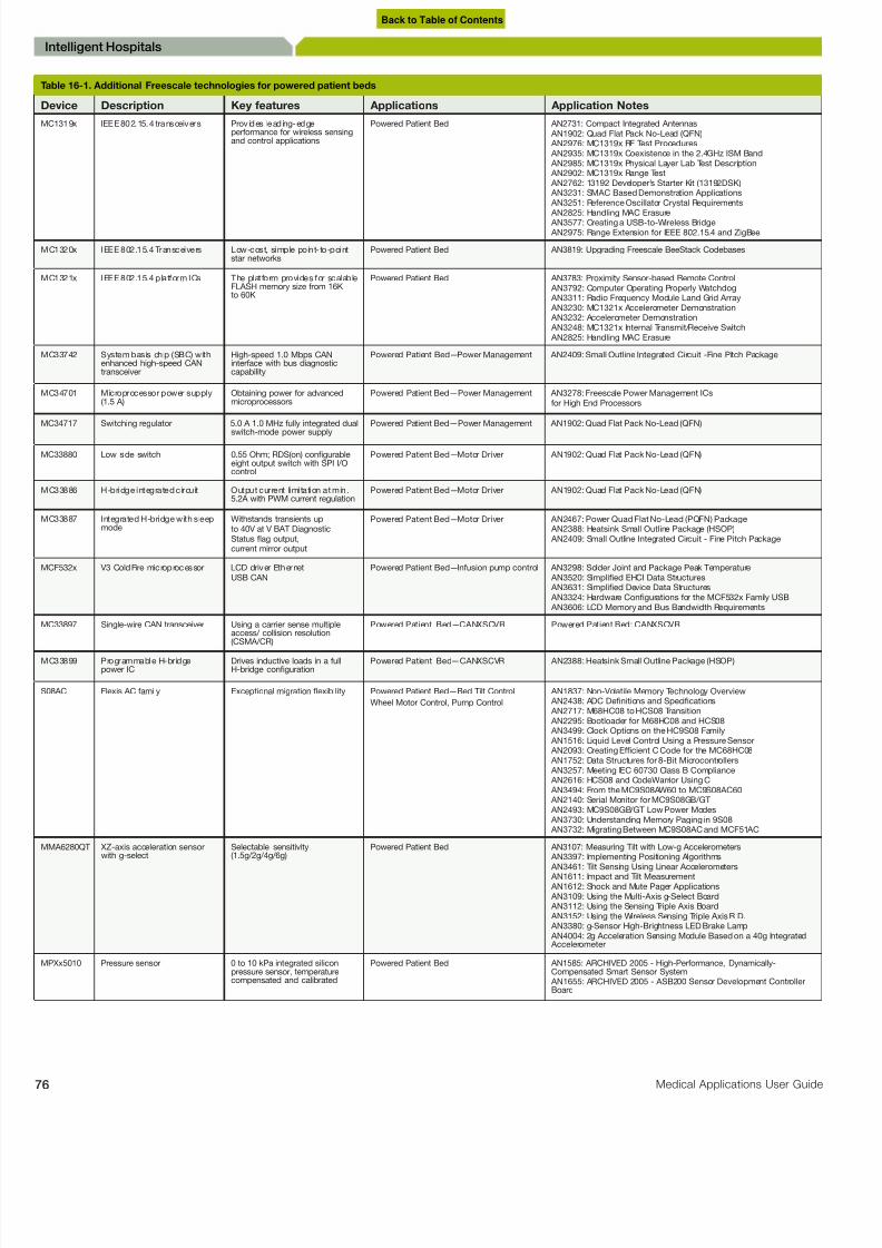
8/10/2019 Microcontroller Digital Blood Pressure Circuit
http://slidepdf.com/reader/full/microcontroller-digital-blood-pressure-circuit 76/88
6 Medical Applications User Guide
Intelligent Hospitals
Table 16-1. Additional Freescale technologies for powered patient beds
Device Description Key features Applications Application Notes
MC1319x IEEE 802.15.4 transceivers Provides leading-edgeperformance for wireless sensingand control applications
Powered Patient Bed AN2731: Compact Integrated Antennas AN1902: Quad Flat Pack No-Lead (QFN) AN2976: MC1319x RF Test Procedures AN2935: MC1319x Coexistence in the 2.4GHz ISM Band AN2985: MC1319x Physical Layer Lab Test Description AN2902: MC1319x Range Test AN2762: 13192 Developer’s Starter Kit (13192DSK) AN3231: SMAC Based Demonstration Applications AN3251: Reference Oscillator Crystal Requirements
AN2825: Handling MAC Erasure AN3577: Creating a USB-to-Wireless Bridge AN2975: Range Extension for IEEE 802.15.4 and ZigBee
MC1320x IEEE 802.15.4 Transceivers Low-cost, simple point-to-pointstar networks
Powered Patient Bed AN3819: Upgrading Freescale BeeStack Codebases
MC1321x IEEE 802.15.4 platform ICs The platform provides for scalableFLASH memory size from 16Kto 60K
Powered Patient Bed AN3783: Proximity Sensor-based Remote Control AN3792: Computer Operating Properly Watchdog AN3311: Radio Frequency Module Land Grid Array AN3230: MC1321x Accelerometer Demonstration AN3232: Accelerometer Demonstration AN3248: MC1321x Internal Transmit/Receive Switch AN2825: Handling MAC Erasure
MC33742 System basis chip (SBC) withenhanced high-speed CANtransceiver
High-speed 1.0 Mbps CANinterface with bus diagnosticcapability
Powered Patient Bed—Power Management AN2409: Small Outline Integrated Circuit -Fine Pitch Package
MC34701 Microprocessor power supply(1.5 A)
Obtaining power for advancedmicroprocessors
Powered Patient Bed—Power Management AN3278: Freescale Power Management ICsfor High End Processors
MC34717 Switching regulator 5.0 A 1.0 MHz fully integrated dual
switch-mode power supply
Powered Patient Bed—Power Management AN1902: Quad Flat Pack No-Lead (QFN)
MC33880 Low side switch 0.55 Ohm; RDS(on) congurableeight output switch with SPI I/Ocontrol
Powered Patient Bed—Motor Driver AN1902: Quad Flat Pack No-Lead (QFN)
MC33886 H-bridge integrated circuit Output current limitation at min.5.2A with PWM current regulation
Powered Patient Bed—Motor Driver AN1902: Quad Flat Pack No-Lead (QFN)
MC33887 Integrated H-bridge with sleepmode
Withstands transients upto 40V at V BAT DiagnosticStatus flag output,current mirror output
Powered Patient Bed—Motor Driver AN2467: Power Quad Flat No-Lead (PQFN) Package AN2388: Heatsink Small Outline Package (HSOP) AN2409: Small Outline Integrated Circuit - Fine Pitch Package
MCF532x V3 ColdFire microprocessor LCD driver EthernetUSB CAN
Powered Patient Bed—Infusion pump control AN3298: Solder Joint and Package Peak Temperature AN3520: Simplied EHCI Data Structures AN3631: Simplied Device Data Structures AN3324: Hardware Congurations for the MCF532x Family USB AN3606: LCD Memory and Bus Bandwidth Requirements
MC33897 Single-wire CAN transceiver Using a carrier sense multipleaccess/ collision resolution(CSMA/CR)
Powered Patient Bed—CANXSCVR Powered Patient Bed: CANXSCVR
MC33899 Programmable H-bridgepower IC
Drives inductive loads in a fullH-bridge conguration
Powered Patient Bed—CANXSCVR AN2388: Heatsink Small Outline Package (HSOP)
S08AC Flexis AC family Exceptional migration flexibility Powered Patient Bed—Bed Tilt Control
Wheel Motor Control, Pump Control
AN1837: Non-Volatile Memory Technology Overview AN2438: ADC Denitions and Specications AN2717: M68HC08 to HCS08 Transition AN2295: Bootloader for M68HC08 and HCS08 AN3499: Clock Options on the HC9S08 Family AN1516: Liquid Level Control Using a Pressure Sensor AN2093: Creating Efcient C Code for the MC68HC08 AN1752: Data Structures for 8-Bit Microcontrollers AN3257: Meeting IEC 60730 Class B Compliance AN2616: HCS08 and CodeWarrior Using C AN3494: From the MC9S08AW60 to MC9S08AC60 AN2140: Serial Monitor for MC9S08GB/GT AN2493: MC9S08GB/GT Low Power Modes AN3730: Understanding Memory Paging in 9S08 AN3732: Migrating Between MC9S08AC and MCF51AC
MMA6280QT XZ-axis acceleration sensorwith g-select
Selectable sensitivity(1.5g/2g/4g/6g)
Powered Patient Bed AN3107: Measuring Tilt with Low-g Accelerometers AN3397: Implementing Positioning Algorithms AN3461: Tilt Sensing Using Linear Accelerometers AN1611: Impact and Tilt Measurement AN1612: Shock and Mute Pager Applications AN3109: Using the Multi-Axis g-Select Board AN3112: Using the Sensing Triple Axis Board AN3152: Using the Wireless Sensing Triple Axis R D. AN3380: g-Sensor High-Brightness LED Brake Lamp AN4004: 2g Acceleration Sensing Module Based on a 40g Integrated Accelerometer
MPXx5010 Pressure sensor 0 to 10 kPa integrated siliconpressure sensor, temperaturecompensated and calibrated
Powered Patient Bed AN1585: ARCHIVED 2005 - High-Performance, Dynamically-Compensated Smart Sensor System AN1655: ARCHIVED 2005 - ASB200 Sensor Development ControllerBoard
Back to Table of Contents

8/10/2019 Microcontroller Digital Blood Pressure Circuit
http://slidepdf.com/reader/full/microcontroller-digital-blood-pressure-circuit 77/88
freescale.com/medical
Medical Imag
Medical Imaging
17.1
IntroductionThe complexities of medical imaging require extraordinary processing
and RF power. Modalities such as magnetic resonance imaging (MRI),
computed tomography (CT) scans and ultrasound all push performance
limits for advanced integrated I/O, rigorous data processing, powerful
display capabilities and high levels of connectivity. These needs are
addressed by Freescale’s family built on Power Architecture® multi-
core processors and RF amplifiers. The Power Architecture family
is designed for applications requiring a rich user interface, complex
displays and network integration. Freescale’s RF power amplifiers
provide the high output power required to achieve the desired
frequency of resonance, or Larmour frequency. These components
are engineered to assist medical imaging equipment manufacturer
meeting their processing and performance needs, to control a rich
interface display and to allow connectivity through various standar
protocols.
Medical Imag
Back to Table of Contents

8/10/2019 Microcontroller Digital Blood Pressure Circuit
http://slidepdf.com/reader/full/microcontroller-digital-blood-pressure-circuit 78/88
8 Medical Applications User Guide
Medical Imaging
7.2
Ultrasound
Ultrasound is a non-invasive medical imaging
echnique used to visualize muscles, tendons,
athological lesions and many internal organs
nd other structures. It plays an important role
uring prenatal care and is commonly used asdiagnostic tool.
One of the most common uses of ultrasound
s for fetal monitoring. Ultrasound uses sound
waves to create images of a fetus inside
uterus. Because it uses sound waves
nstead of radiation, ultrasound is safer than
-rays. Gradually, ultrasound has become an
ncreasingly important part of prenatal care,
roviding information that can help the doctor
o plan the monitoring of a pregnant woman,
hus improving the chances of successful
regnancy.
7.3
How Ultrasound Works
Ultrasound is based on bouncing sound
waves into the body of the developing fetus.
he echoes produced by these waves are
onverted into a picture called a sonogram,
which appears on a monitor. This technique is
lso often referred to as sonography or sonar.
ropagation and reflection rules that govern
lectric signals are also applied to ultrasound.
A transmission line must be terminated in its
haracteristic impedance to avoid reflections.
n the equation below, acoustic impedance
is a fundamental property of matter and
s related to the density ρ and the velocity
f sound v : Z = ρv. The fraction of energy
R refracted at the normal interface of two
ifferent tissue types is:
7.4
Transducer
he transducer is the element that converts
lectrical signals into ultrasound waves. It
onsists of a set of transmitter and receiver
ransducers arranged in a linear array. A
nique transducer is explained in Chapter
, Fetal Heart Rate Monitor . Pulse trains are
sent by transmitter transducers, and receiver
transducers receive bounced waves. The
operating frequency for this kind of device is
from 5 MHz to 8 MHz.
The blocks needed for signal conditioning/
pulse generator blocks are shown in Figure
17-3.
Figure 17-1: Ultrasound General Block Diagram
MCU/MPU
Display Keypad
Transducer
PWM
ADC
Power Management
PulseGenerator
SignalConditioning
MCU Optional Peripherals Analog Sensors
Figure 17-2: Ultrasound Transducer Diagram
TX
RX
TX
RX
TX
RX
TX
RX
P a t i en t
R =(Z
2
- Z1
)
(Z2+Z
1 )
2
Back to Table of Contents

8/10/2019 Microcontroller Digital Blood Pressure Circuit
http://slidepdf.com/reader/full/microcontroller-digital-blood-pressure-circuit 79/88
freescale.com/medical
Medical Imag
17.5
Multiplexer for Tx/RxTransducers
This block may be implemented using analog
gates controlled by the MCU/MPU. This
allows the use of transducers as transmitters,
and later the ability to switch the multiplexerto use as receivers. Multiplexing reduces the
number of connections needed, because the
transducers array can range from 8 to more
than 256.
17.6
Instrumentation Amplifierand Variable Gain
AmplifierUltrasonic wave energy sent though a
patient’s body is very attenuated by multiple
factors (absorbing, attenuation due to the
medium, inverse square law, etc.). Before
processing information, the instrumentation
amplifier conditions the signal to adequate
levels, and eliminates common-mode noise.
A variable gain amplifier is used due to
exponential attenuation of the bounced
waves. Applying an exponential gain reduces
the effect of the attenuation. Figure 17-4
shows the behavior of this element.
Figure 17-5 shows a simple analog
implementation of the circuit (left side). At the
right side, a block diagram of a control system
is shown. This can be implemented by an
MPU using software.
17.7
Beamformer
A beamformer is a device that directs waves
in a specific direction by means of algorithms
that control the transducer array to form
a wave front that generates constructive
interference. This is used to generate the
sweep required to build the image to be
shown. Figure 17-7 is a diagram of the
direction of propagation of waves controlled
by a beamformer.
Figure 17-4: Variable Gain Amplifier Function
A m p l i t u d e
A m p l i t u d e
G a i n
Time
Fixed
Gain
Time
Figure 17-3: Ultrasound Probe Block Diagram
RXBeamformer
Multiplexer for TX/RX
Transducers
T r a n s d u c e r A r r a y
High-SpeedHigh-Resolution
ADC
TXBeamformer
Blocks within MPU
Hi-speedDAC
High-VoltageTX Amplifier
Instrumentation Amplifier
Variable Gain Amplifier
Beamformer ControlSystem
Signal fromOperational Amplifier
Variable Amplitude
Signal
4.7kΩ
1MΩ
1MΩ
R2 R3 Out
Q1
R1
Figure 17-5: Analog Implementation of Variable Gain Amplifier
Back to Table of Contents

8/10/2019 Microcontroller Digital Blood Pressure Circuit
http://slidepdf.com/reader/full/microcontroller-digital-blood-pressure-circuit 80/88
0 Medical Applications User Guide
Medical Imaging
7.8
MicroprocessorsMPC5121e
he Freescale MPC5121e integrated
rocessor uses an e300 CPU core based on
ower Architecture technology. It provides an
xceptional computing platform for multimedia
nd is excellent for embedded solutions that
equire graphics, a graphical user interface
nd network connectivity.
o connect a screen to show the processed
mages received by the ultrasound probe, this
rocessor has the following characteristics:
MBX Lite 2D/3D graphics engine licensed
from Imagination Technologies™ Group
Plc.; includes PowerVR® geometry
processing acceleration.
Integrated display controller supports a
wide variety of TFT LCD displays with
resolution up to 1280 × 720 at a maximum
refresh rate of 60 Hz and a color depth up
to 24 bits per pixel.
Key features
e300 core built on Power Architecture
technology
Up to 400 MHz performance and 760 MIPS
AXE, a 32-bit RISC audio accelerator
engine
PowerVR MBX Lite 2-D/3-D graphics
engine (not included in the MPC5123)
DIU integrated display controller supports
up to XGA resolution
12 programmable serial controllers (PSC)
MobileGT Products
he MPC5121e and MPC5123 are the latest
ddition to the mobileGT family of processors.
reescale is working closely with mobileGT
lliance member companies to provide
widespread firmware and software driver
upport.
7.9
Digital X-Ray
Digital X-ray is a form of X-ray imaging where
igital X-ray sensors are used instead of
raditional photographic film.
Figure 17-6: Control System Block Diagram
Variable Gain
Amplifier
OutIn
ExtractedOutput Signal
G
H
Figure 17-7: Concentrated Energy Diagram of a Beamformer
Z
Y
X
Back to Table of Contents

8/10/2019 Microcontroller Digital Blood Pressure Circuit
http://slidepdf.com/reader/full/microcontroller-digital-blood-pressure-circuit 81/88
freescale.com/medical
Medical Imag
17.10
Analog Front End
The analog part is composed of a cathode
ray tube and a grid of photo detectors.
Because these generate current, it is
necessary for each photo detector to have a
transimpedance amplifier. It is also necessary
to have an analog multiplexer to allow
different measurements depending on the
radiography.
17.11
Photo Detector Grid
The X-ray emitter generates cathode rays
that pass through the body. A grid of photo
detectors receives the light, providing
information and signals to be processed
before the system shows a result.
17.12
DSP/DSC
The signal processing and signal conditioning to
generate radiography is through a DSP or DSC.
The Freescale 56800/E family offers up to
120 MIPS processor performance. These
processors combine, on a single chip,
the processing power of a DSP and the
functionality of an MCU with a flexible set of
peripherals to create a cost-effective solution
for industrial control, motion control, home
appliances, general-purpose inverters, smart
sensors, advanced lighting, fire and security
systems, switched-mode power supply,
power management and medical monitoring
applications.
In X-ray applications it is necessary to
implement signal processing and image
recognition. Freescale’s DSP and controller
portfolio includes the following processors
designed to perform mathematically intensivecomputations for a single group of tasks in
real time. DSPs are highly specialized and
normally used as embedded controllers.
For medical applications Freescale offers
the DSP56300 core DSP family. These DSPs
offer a rich instruction set and low power
dissipation, as well as speed and power to
enable wireless, telecommunications and
multimedia products. The DSP56300 core
includes a barrel shifter, 24-bit addressing,
Figure 17-8: Digital X-Ray General Block Diagram
MCU Optional Peripherals Analog Sensors
ADC
SPI/SCI
Photo
Detector Grid
MCU/MPU
DSP/DSC
Capacitive
Sensing
andTouch Screen
Display
X-Ray
Emissor
Power
Management
Transimp
Amp
MUX
USB
Figure 17-9: General Analog Configuration
ADC
PhotoDetector Grid
X-Ray
Emissor
Transimp
Amp
MUX
ADC
Figure 17-10: Photo Detector Configuration
3 MΩ
3 pF
MUX
Back to Table of Contents

8/10/2019 Microcontroller Digital Blood Pressure Circuit
http://slidepdf.com/reader/full/microcontroller-digital-blood-pressure-circuit 82/88
2 Medical Applications User Guide
Medical Imaging
nstruction cache and DMA, and offers 100
MMACS using an internal 100 MHz clock at
.0–3.6 volts. The DSP56300 family of devices
s intended for use in telecommunication
pplications such as multi-line voice/data/
ax processing, video conferencing, audio
pplications, control and general digital signal
rocessing.
56800/E Digital Signal Controller
Products
6-bit StarCore-based DSPs
StarCore SC3850 (MSC815x)
StarCore SC3400 (MSC8144)
StarCore SC140 (MSC811x, MSC812x)
StarCore SC1400 (MSC711x, MSC712x)
4-bit general purpose DSPs
Symphony DSP56xxx
DSP563xxDSP5685x
DSP56F80x/2x
MC56F81xx/83xx
MC56F80xx
6-bit 56800/E digital signal controllers
7.13
Capacitive Sensing andTouch Screen Display
he MC34940 is intended for cost-sensitive
pplications where non-contact sensing
f objects is desired. When connected to
xternal electrodes, an electric field is created.
he MC34940 detects objects in this electric
eld. The IC generates a low-frequency
ine wave, which is adjustable by using an
xternal resistor and is optimized for 120
Hz. The sine wave has very low harmonic
ontent to reduce harmonic interference.
he MC34940 also contains support circuits
or a microcontroller unit (MCU) to allow the
onstruction of a two-chip E-field system.
or more information about touch panel
pplications, see the application note titled
ouch Panel Applications Using the MC34940/
MC33794 E-Field IC (document AN1985),
vailable at www.freescale.com.
or Wireless Communication, Power
Management, Keypad, and Speaker
mplementation modules, see Chapter 3
elehealth Systems Introduction.
Figure 17-11: 56800/E Digital Signal Controller Products
P E R F O R M A N C E
FUNCTIONALITY
DIGITAL SIGNAL CONTROLLERS
MC56F80xx
• 32 MHz
• 12 KB-64 KB Flash
• 2 KB -8 KB RAM
• 28-pin–64-pin
DSP56F80x
DSP56F82x
• 40 MHz
• 24 KB-140 KB Flash
• 4 KB -12 KB RAM
• 32-pin–160-pin
MC56F81xx
MC56F83xx
• 40~ 60 MHz
• 40 KB-576 KB Flash
• 8 KB -36 KB RAM
• 48-pin–160-pin
DSP5685x
• 120 MHz
• 2 KB boot ROM
• 20 KB–128 KB RAM
• 81-pin–144-pin
56F8XXX Digital Signal Controllers
M e m o r y a n d F e a t u r e s
Figure 17-12: Digital Signal Processors and Controllers Portfolio
56F83xxSeries
56F8300 SeriesUp to 60 MMACS32-512 KB Program Flash48–160 pins-40˚C to +125˚C
Applications• Industrial control
• Security systems• Motor control
• Appliances• Washing machines
• Refrigeration/dishwashers• Inductive cooking
Advancd Lighing Control• HBLEDs
• LCD backlightDigital Power Conversion
• UPS electrical protection• AC-DC power supply
Automotive• Power steering
• ABS braking• Wire braking
56F81xxSeries
56F8300 SeriesUp to 40 MMACS32-512 KB Program Flash48–160 pins-40˚C to +105˚C
56F80xxSeries
56F8000 SeriesUp to 32 MMACS16-128 KB Program Flash32–64 pins-40˚C to +125˚C
Peripherals Flash RAM Core Plus Features
Figure 17-13: MC56F800x: MC56F8006 and MCF56F8002 Digital Signal Controllers
Memory
Options
6 KB
8 KB2 KB SRAMFlash
High-Speed SCI
System Clock Control(COSC, ROSC, PLL)
2 12-bit
ADCs
3 AnalogComparators
Power SuperVisor
2 2x-16xWideband PGAs
16-bit PeriodicInterval Timer
VoltageRegulators
ProgrammableDelay Block (PDB)
InterruptController
2 16-bit Timers
SPI PC COP
6 Output PWM
56800E Core/32MIPS
System IntegrationModule (SIM)
Back to Table of Contents

8/10/2019 Microcontroller Digital Blood Pressure Circuit
http://slidepdf.com/reader/full/microcontroller-digital-blood-pressure-circuit 83/88
freescale.com/medical
Summ
Summary
Applications Freescale Productus Freescale Differentiators
Diagnostics and Therapy
Ablation Laser Anesthesia Unit Monitors
Clinical Patient MonitoringClinical/Surgical EquipmentDebrillators/AEDSDialysis EquipmentElectrocardiogram (ECG or EKG)ElectromyographFitness/WellnessHospital Admission
MachinesImplantable DevicesInfusion Pumps
Ventilator/RespiratorsWound Management
Flexis family: Low-end to high-end pin-to-pin compatibility, 8- and 32-bit
ColdFire technology: MCF5225x 32-bit, USB, Ethernet
Digital signal controllers (DSCs): MC56F801x, MC56F802x, MC56F8100, MC56F8300i.MX Series (ARM® Core, 32-bit)
−i.MX257: LCD controller w/touch screen, LCD, USB, Ethernet, camera, CAN
−i.MX357: adds graphics
−i.MX515: adds video
High-Performance 32-bit Microprocessors (MPUs): MPC5121e, MPC8377, MPC8641,MPC8535, P1022, P1013
Wireless: MC1322x (IEEE 802.15.4/ZigBee® technology)
Pressure sensors: MPXV5004G, MPXV4006G, MPL115A, MPXC2011DT1, MPX12GS,MPX5010DP, MPX2010DP, MPXV2053GVP, MPXV5100G, MPX2300DT1
Touch sensors: MPR03x, MPR121QR2
Accelerometers: MMA736xL, MMA7455L
Power management: MPC18730, MC13883, MC13892, MC34700, MC34712, MC34713,MC34716, MC34717
Motor drivers (H-bridges): MC33887, MPC17511, MPC17C724
LED backlight: MC34844, MC34845
Radio frequency (RF) LDMOS power transistor: MRF6VP11KH
Product Differentiators• Highest quality standards
• Product life: 15-year longevity• Breadth and scalability of portfolio• Low-power solutions• i.MX series, Flexis, ColdFire: High level of integration - Connectivity (USB and Ethernet) - LCD control (graphic and segment) - Internal memory - High precision analog• ColdFire: embedded high-performance digital signal processo(DSP) functionality with integrated MAC• i.MX series: video and graphics acceleration• Strong RF portfolio - Highest gain - Exceptional efciency - Higher power densitySolution Differentiators• Touch U/I suited for sterile clinical equipment• Cost-effective, amplied, small form factor sensors with high
sensitivityUSB for Medical• Continua ready, IEEE compliant PHDC USB software stack available
Home Portable
Blood Pressure Monitor (BPM)Diabetes Care (blood glucose monitor and insulin pumps)Digital ScaleDigital ThermometerFetal Heart Rate MonitorHeart Rate Monitor (HRM)Pulse OximetryTelehealth/Telemonitoring
Flexis Families (8- and 32-bit)
- MC9S08QE, MCF51QE: general purpose, low power
- MC9S08JM, MCF51JM: USB, low power
- MC9S08AC, MCF51AC: FlexTimer
8-bit Microcontrollers (MCUs)
- MC9S08LL: low power, segment LCD
- MC9S08JS: low power, USB
Ultra Low-End 8-bit MCUs
- MC9RS08KA: general purpose
- MC9RS908LA, MC9RS08LE: segment LCD controllers
ColdFire Technology
- MCF5225x: 32-bit, USB, Ethernet
i.MX Series (ARM Core, 32-bit)
- i.MX233: USB, LCD controller with touch-screen
- i.MX257: LCD, USB, Ethernet, camera
Wireless: MC1322x (IEEE 802.15.4/ZigBee technology)
Pressure sensors: MPX2300DT1, MPXV5050GC6, MPXM2053GS (blood
pressure monitoring)
Touch sensors: MPR03x, MPR121QR2, proximity IP
Accelerometers: MMA736xL, MMA7455L (arm angle detection for blood pressuremonitoring), MMA7660 (portrait/landscape)
Power management: MPC18730, MC13883, MC3467x, MC34704, MC13892
Motor drivers (H-bridges): MC33887, MPC17511, MPC17C724, MC33931,
MC33932, MC33926
LED backlight: MC34844, MC34845
Product Differentiators• Highest quality standards• Product life: 15 year longevity• MC9S08QE, MC9S08LL: low power consumption to enablelonger battery life - 370 nA, 1.8V, 6 usec wake up in lowest power mode• MC9S08LL: superior LCD controller IP• Connectivity: USB, ZigBee• Pressure sensors: packaged specically for medical applicatio• High-end microprocessors with graphics accelerationSolution Differentiators• Solutions that enable a lower system cost• Touch U/I suited for sterile hand-held monitors• Cost-effective, amplied, small form factor sensors with high sensitivity• USB for medical: Continua ready, IEEE compliant PHDC USB software stack available
Imaging
Bone DensitometerComputed Tomography (CT)Fluoroscopy, AngiographyMagnetic Resonance Imaging (MRI)Positron Emission
Tomographer (PET)Ultrasound X-Ray And Related Applications
ColdFire Microprocessors (MPUs)
−MCF5227: 32-bit, USB, graphical LCD controller
−MCF532x: 32-bit, USB, graphical LCD controller, Ethernet
−MCF5445x: 32-bit USB, 2x Ethernet, PCI
High performance: MPC837x, MPC831x, MPC85xx, P2020
High-end image processing: MPC512x, MPC8610, MSC8122, MSC8144, MPC8536,
MPC8315, MSC8144, MAC8154, MSC8156, P1022i.MX Series (ARM Core)
−i.MX257
−i.MX357: 32-bit, LCD, USB, Ethernet, video and camera
−i.MX515: 32-bit, Video, Graphics, Ethernet, LCD with touch screen, USB
Wireless: MC132xx ZigBee technology
Accelerometers: MMA736xL (vibration sensing)
Touch sensors: MPR03x, MPR121QR2
Power management: MPC18730, MC13883, MC13892, MC34704, MC34712,MC34713, MC34716, MC34717
LED backlight: MC34844, MC34845
General purpose ampliers
High-power RF ampliers: MRF6VP11KH, MRF6VP2600H, MRF6V4300N
Product Differentiators• Highest quality standards• Product life: 15-year longevity• Breadth and scalability of portfolio• Low-power solutions• i.MX series, Flexis, ColdFire: high level of integration
- Connectivity (USB and Ethernet) - LCD control - Internal memory - High precision analog• ColdFire: embedded high-performance digital signal processo
(DSP) functionality with integrated MAC• i.MX series: video and graphics acceleration• Strong RF portfolio - Highest gain - Exceptional efciency - Higher power density• High-performance processors: PCI Express® support and Se ATA (SATA) for storing images
Solution Differentiators• Touch U/I suited for sterile clinical equipment• Cost-effective, amplied, small form factor sensors with high
sensitivity• AltiVec® engine for image processing
Back to Table of Contents

8/10/2019 Microcontroller Digital Blood Pressure Circuit
http://slidepdf.com/reader/full/microcontroller-digital-blood-pressure-circuit 84/88

8/10/2019 Microcontroller Digital Blood Pressure Circuit
http://slidepdf.com/reader/full/microcontroller-digital-blood-pressure-circuit 85/88
freescale.com/medical
Appen
Digital Filter Examples
Digital FIR vs. IIR Filters
A digital finite impulse response (FIR) filter can
implement non-realizable analog functions,
with many more multiplies, adds and data
moves.
A digital infinite impulse response (IIR) filter
provides a digital imitation of analog filters.
It generally has the fewest operations, but is
often 10x more efficient.
Signal Reconstruction
To reconstruct the signal to the original one,
we use the digital signal reconstructed by the
DAC and then use passive filters to shape it in
a smooth manner. See Figure A-5.
Figure A-3: Anti-Aliasing Filter and Sampling
Analog
Low-Pass
Filter
Sample
and Hold
ADC
Sample Rate
1.6060e+000
2.4394e+000
2.2457e+000
1.4378e+000
7.7448e-001
7.9937e-001
1.4447e+0002.0849e+000
2.0000e+000
9.1704e-001
-7.6317e-001
-2.2173e+000
Signal + Noise LPF (Signal + Noise) Numbers that we can
use in DSP technique Volts
Time
Volts
Time
Figure A-4: Low- and High-Pass Filters
Low Pass
High Pass
Digital Filters
Sample
and Hold
ADC
Sample Rate
y(n)+0.0732x(n)=0.1464x(n-1)+0.0732x(n-2)
+1.099y(n-1)-0.3984y(n-2)
DAC
Sample Rate
1.6060e+000
2.4394e+000
2.2457e+000
1.4378e+000
7.7448e-001
7.9937e-001
1.4447e+000
2.0849e+000
2.0000e+000
9.1704e-001
-7.6317e-001
-2.2173e+000
1.6060e+000
2.4394e+000
2.2457e+000
1.4378e+000
7.7448e-0017.9937e-001
1.4447e+000
2.0849e+000
2.0000e+000
9.1704e-001
-7.6317e-001
-2.2173e+000
1.6060e+000
2.4394e+000
2.2457e+000
1.4378e+000
7.7448e-001
7.9937e-001
1.4447e+000
2.0849e+000
2.0000e+000
9.1704e-001
-7.6317e-001
-2.2173e+000
Numbers that we can
use in DSP techniques
Figure A-5: Signal Reconstruction
Analog
Low-PassFilter
Analog
Low-Pass
Filter
DACReconstruction Filters
Sample Rate
1.6060e+000
2.4394e+000
2.2457e+000
1.4378e+000
7.7448e-001
7.9937e-001
1.4447e+000
2.0849e+000
2.0000e+000
9.1704e-001-7.6317e-001
-2.2173e+000
1.6060e+000
2.4394e+000
2.2457e+000
1.4378e+000
7.7448e-001
7.9937e-001
1.4447e+000
2.0849e+000
2.0000e+000
9.1704e-001
-7.6317e-001
-2.2173e+000
Volts
Volts
Volts
Time
Volts
Time
y(n) =N-1
a(i)x(n-i)
i=0
y(n) =
N-1
a (i )x (n -i ) + b (j )y (n -j ), M >N
i=0
M
j=1
Back to Table of Contents

8/10/2019 Microcontroller Digital Blood Pressure Circuit
http://slidepdf.com/reader/full/microcontroller-digital-blood-pressure-circuit 86/88
6 Medical Applications User Guide
Appendix
Freescale Technologies
ColdFire MAC architecture enables DSP
algorithms
IIR and FIR filters gain performance with
MAC instructions
Single instruction: multiply-accumulate with
load
• Multiply two 16-bit word or 32-bit
longword operands
• Add 32-bit product to 32-bit accumulator
(ACC) register
• Load 32-bit longword for next instruction
and increment address register (ptr)
Sample analog accelerometer data with
ADC (3 kHz)
Execute two parallel digital filters
Send via USB: raw and filtered data,
timestamp, filter execution cycles
or more information, download the PDF
ColdFire Technology and DSP from http://
reescale.com/les/dsp/doc/ref_manual/CFD-
PTechnology_DSP.pdf.
nstrumentation Amplifier
n medical instrumentation it is common
o process signals with a lot of noise and
mall amplitude. For these reasons annstrumentation amplifier, which has high
ntrance impedance and high CMRR, is often
sed. This device can be built with discrete
lements or can be obtained pre-built. The
mplifier gets the differential between the
ignal and amplifier depending on the gain,
nd the gain determines the signal amplitude.
he gain recommended for medical
pplications is 1000 because the signal
scillates around 1mV, and with this gain
he signal can be amplified up to 1V. It is
lso recommended that for the first part you
enerate a gain of only 10 to avoid amplifier
ommon-mode signals. Only filter the noise
ignals with this part, and amplify the rest of
he signal with the differential amplifier.
A 1 = 1+
R2
R1
R1+R
2
R1
A 1 = A
1 = A
1 A
2
R2 = (A
1R
1 )-R
1
R4 = A
2R
3
A 2 =
R4
R3
Values to obtain a Signal Around 1V: Low Gain: 10, High gain: 100, Total gain: 1000
Figure A-7: Instrumentation Amplifier Design Diagram
Vi1
Vid=(Vi
1-Vi
2 )
Vid/2R1 Vid(1+2R
2 /2R
1 )
Vo=R4 /R
3( 1+R
2 /R
1 )Vid
A=Vo/Vid
R3
R3
R4
R4
R2
2R1
R2
Vi2
Figure A-6: ColdFire Demo Board (M52221DEMO)
ADC
Filter 1
Filter 2USB Accelerometer
Mechanical
Oscillator
DebugTimers
V2 ColdFire MCU Laptop Host
Lab View
Back to Table of Contents

8/10/2019 Microcontroller Digital Blood Pressure Circuit
http://slidepdf.com/reader/full/microcontroller-digital-blood-pressure-circuit 87/88
freescale.com/medical
Appen
Filter Design
A lot of noise is present in biophysical signals.
To attenuate this noise, low pass filters and
high pass filters are used to amplify the small
AC components and reject DC components.
The filters allow only the useful signals, which
helps make a better diagnosis. These filterscan be built with passives or actives (op
amps) depending on the application, although
active filters are more effective at rejecting
noise. Passive filters are more cost-effective
and in some cases are suitable. Sometimes
the MCU does not have a DAC. This can be
built by the PWM module and external low
pass filter to convert digital data to analog
data.
Medical PerspectiveThe following chart outlines some medical
applications based on medical professionals’
specialties.
Medical Applications Guide
Medical Perspective
Medical
ChronicHeart Failure
Stroke
Spirometer, Ventilator
Surgical Obstetrics and
Gynecology Pediatrics Imaging Administrative Nurses Labora
O.R. Neonatology MRI Intelligent
Hospitals Drug Delivery Blood G
Orthopedics
Cervix
Neoplasm
Surgery PET Scanner Inventory Monitoring Bloo
Chemi
Anesthesia Neonatal
Intensive
Care UnitMammary
Gland
Neoplasm
Acute
Fetal StressSyndrome
Ultrasound Admission Microsc
Fertility
Tormography
Organ
Transplant
Fetal Growth
Digital X-Ray
Urology Endoscopy
Otolaryngology
Neurosurgery
Administrative
Endoscopy
Telemonitoring,Echocardiography,EKG, Urometer
Diabetes Mellitus
Peptide C, Hb 1Ac,
Glucometer, Ketones,
Urine Glucose,
Insulin Pumps
EKG, HeartEnzymes
COPD
Blood PressureMonitor
Hypertension
Genome, RadiationExposure Meter
Cancer
Holter, EKG
Arrhythmias
HIV/AIDS
Alzheimer'sDisease
Hemodialysis,Ultrasound, BloodGases
Renal FailureChronic
Renal Failure
Acute MyocardialInfarction
Type Circuit Cut frequency Equation
Band-passpassive
0.1 Hz–150 Hz
Heart operating range
Reject-bandpassive
40 Hz–60 Hz
Noise signal
from the line
Band-pass active 400 Hz–4 KHz
Sound wave
bounced (range
depends of the
transducer)
Low-pass active 150 Hz
Heart operating range (ifthe passive filter is notenough, use an activefilter)
High-pass filteractive
Some medical applications
Not specific
ƒ0 = 1
2πRC
ƒ0 =
1
2π R ARBC AC
B
Back to Table of Contents

8/10/2019 Microcontroller Digital Blood Pressure Circuit
http://slidepdf.com/reader/full/microcontroller-digital-blood-pressure-circuit 88/88
Home Page:
freescale.com
Web Support:freescale.com/support
USA/Europe or Locations Not Listed:
Freescale Semiconductor
Technical Information Center, EL516
2100 East Elliot Road
Tempe, Arizona 85284
+1-800-521-6274 or +1-480-768-2130
freescale.com/support
Europe, Middle East, and Africa:
Freescale Halbleiter Deutschland GmbH
Technical Information Center
Schatzbogen 7
81829 Muenchen, Germany
+44 1296 380 456 (English)
+46 8 52200080 (English)
+49 89 92103 559 (German)
+33 1 69 35 48 48 (French)
freescale.com/support
Japan:
Freescale Semiconductor Japan Ltd.
Headquarters
ARCO Tower 15F1-8-1, Shimo-Meguro, Meguro-ku,
Tokyo 153-0064
Japan
0120 191014 or +81 3 5437 9125
Asia/Pacific:
Freescale Semiconductor China Ltd.
Exchange Building 23F
No. 118 Jianguo Road
Chaoyang District
Beijing 100022
China
+86 10 5879 8000
For Literature Requests Only:
Freescale Semiconductor Literature
Distribution Center
1-800-441-2447 or +1-303-675-2140
Fax: +1-303-675-2150
LDCForFreescaleSemiconductor@
hibbertgroup.com
How to Reach Us
For additional information
about Freescale medical
solutions, please visit
reescale.com/medical.
nformation in this document is provided solely to enable system and software implementers to use Freescale Semiconductor products. There are no express or implied copyright licenses granted
hereunder to design or fabricate any integrated circuits or integrated circuits based on the information in this document.
Freescale Semiconductor reserves the right to make changes without further notice to anyproducts herein. Freescale Semiconductor makes no warranty, representation, or guarantee regarding the
suitability of its products for any particular purpose, nor does Freescale Semiconductor assume any liability arising out of the application or use of any product or circuit, and specifically disclaims any
ability, including without limitation consequential or incidental damages. “Typical” parameters that may be provided in Freescale Semiconductor data sheets and/or specifications can and do vary in
Back to Table of Contents