microplasma 25;microplasma 55;microplasma 105 - ewm-sales.com · for your safety notes on the use...
TRANSCRIPT

Operating instructions
EN
Welding machine
Microplasma 25 Microplasma 55 Microplasma 105
099-007027-EW501 Observe additional system documents! 28.08.2018

General instructions
WARNING
Read the operating instructions!
The operating instructions provide an introduction to the safe use of the products.
• Read and observe the operating instructions for all system components, especially the
safety instructions and warning notices!
• Observe the accident prevention regulations and any regional regulations!
• The operating instructions must be kept at the location where the machine is operated.
• Safety and warning labels on the machine indicate any possible risks.
Keep these labels clean and legible at all times.
• The machine has been constructed to state-of-the-art standards in line with any applicable
regulations and industrial standards. Only trained personnel may operate, service and
repair the machine.
• Technical changes due to further development in machine technology may lead to a
differing welding behaviour.
In the event of queries on installation, commissioning, operation or special conditions at the
installation site, or on usage, please contact your sales partner or our customer service
department on +49 2680 181-0.
A list of authorised sales partners can be found at www.ewm-group.com/en/specialist-dealers.
Liability relating to the operation of this equipment is restricted solely to the function of the equipment. No
other form of liability, regardless of type, shall be accepted. This exclusion of liability shall be deemed
accepted by the user on commissioning the equipment.
The manufacturer is unable to monitor whether or not these instructions or the conditions and methods
are observed during installation, operation, usage and maintenance of the equipment.
An incorrectly performed installation can result in material damage and injure persons as a result. For this
reason, we do not accept any responsibility or liability for losses, damages or costs arising from incorrect
installation, improper operation or incorrect usage and maintenance or any actions connected to this in
any way.
© EWM AG
Dr. Günter-Henle-Strasse 8
56271 Mündersbach Germany
Tel.: +49 2680 181-0, Fax: -244
Email: [email protected]
www.ewm-group.com
The copyright to this document remains the property of the manufacturer.
Copying, including extracts, only permitted with written approval.
The content of this document has been prepared and reviewed with all reasonable care. The information
provided is subject to change; errors excepted.

Contents Notes on the use of these operating instructions
099-007027-EW501 28.08.2018 3
1 Contents 1 Contents .................................................................................................................................................. 3
2 For your safety ....................................................................................................................................... 6 2.1 Notes on the use of these operating instructions .......................................................................... 6 2.2 Explanation of icons ....................................................................................................................... 7 2.3 Part of the complete documentation .............................................................................................. 8 2.4 Safety instructions .......................................................................................................................... 9 2.5 Transport and installation ............................................................................................................ 13
3 Intended use ......................................................................................................................................... 14 3.1 Applications .................................................................................................................................. 14 3.2 Software version .......................................................................................................................... 14 3.3 Documents which also apply ....................................................................................................... 15
3.3.1 Warranty ....................................................................................................................... 15 3.3.2 Declaration of Conformity ............................................................................................. 15 3.3.3 Welding in environments with increased electrical hazards ......................................... 15 3.3.4 Service documents (spare parts and circuit diagrams) ................................................ 15 3.3.5 Calibration/Validation ................................................................................................... 15
4 Machine description – quick overview .............................................................................................. 16 4.1 Front view / side view from left .................................................................................................... 16 4.2 Rear view / side view from right ................................................................................................... 18 4.3 Machine control – Operating elements ........................................................................................ 20
4.3.1 Overview of control sections ........................................................................................ 20 4.3.1.1 Control section A ........................................................................................... 21 4.3.1.2 Control section B ........................................................................................... 22
4.4 Operating the machine control ..................................................................................................... 24 4.4.1 Main screen .................................................................................................................. 24 4.4.2 Welding power setting .................................................................................................. 24 4.4.3 Welding parameter setting in the operation sequence ................................................. 24 4.4.4 Setting advanced welding parameters (Expert menu) ................................................. 24 4.4.5 Changing basic settings (machine configuration menu) .............................................. 24 4.4.6 Welding data display .................................................................................................... 25 4.4.7 Setting the welding current (absolute/percentage) ....................................................... 25
5 Design and function ............................................................................................................................. 26 5.1 Transport and installation ............................................................................................................ 26
5.1.1 Ambient conditions ....................................................................................................... 26 5.1.1.1 In operation ................................................................................................... 26 5.1.1.2 Transport and storage ................................................................................... 26
5.1.2 Machine cooling ............................................................................................................ 26 5.1.3 Workpiece lead, general ............................................................................................... 27 5.1.4 Notes on the installation of welding current leads ........................................................ 27 5.1.5 Stray welding currents .................................................................................................. 28 5.1.6 Mains connection .......................................................................................................... 29
5.1.6.1 Mains configuration ....................................................................................... 29 5.1.7 Shielding and plasma gas supply ................................................................................. 29 5.1.8 Pressure regulator connection ..................................................................................... 30
5.1.8.1 Shielding gas hose connection ..................................................................... 30 5.1.8.2 Gas test ......................................................................................................... 31 5.1.8.3 Automatic gas post-flow ................................................................................ 31
5.1.9 Welding torch cooling system ....................................................................................... 32 5.1.9.1 Cooling unit connection ................................................................................. 32 5.1.9.2 Connection of external recooling unit ............................................................ 33
5.1.10 Welding torch and workpiece line connection .............................................................. 34 5.1.10.1 Plasma welding ............................................................................................. 34 5.1.10.2 TIG welding ................................................................................................... 35 5.1.10.3 Connection assignment, welding torch control cable .................................... 36
5.1.11 Intermediate hose package strain relief ....................................................................... 36 5.2 Plasma welding ............................................................................................................................ 38
5.2.1 Welding task selection .................................................................................................. 38 5.2.1.1 Setting welding procedure ............................................................................ 38

Contents Notes on the use of these operating instructions
4 099-007027-EW501 28.08.2018
5.2.2 Pilot arc ......................................................................................................................... 38 5.2.2.1 Adjust pilot arc currents ................................................................................. 39
5.2.3 Expert Menu (Plasma) .................................................................................................. 40 5.3 TIG welding .................................................................................................................................. 41
5.3.1 Welding task selection .................................................................................................. 41 5.3.2 Arc ignition .................................................................................................................... 42
5.3.2.1 HF ignition ..................................................................................................... 42 5.3.2.2 Liftarc ............................................................................................................. 42 5.3.2.3 Automatic cut-out .......................................................................................... 42
5.3.3 TIG antistick .................................................................................................................. 42 5.3.4 Expert menu (TIG) ........................................................................................................ 43 5.3.5 Aligning the cable resistance ........................................................................................ 44
5.4 Operating modes (functional sequences) .................................................................................... 45 5.4.1 Explanation of symbols ................................................................................................. 45 5.4.2 Non-latched mode ........................................................................................................ 46 5.4.3 Latched mode ............................................................................................................... 47 5.4.4 spotArc .......................................................................................................................... 48 5.4.5 spotmatic (Plasma) ....................................................................................................... 49 5.4.6 spotmatic (TIG) ............................................................................................................. 50 5.4.7 Non-latched operation, version C ................................................................................. 51
5.5 Recurring welding tasks ............................................................................................................... 52 5.6 Pulse welding ............................................................................................................................... 52
5.6.1 Automated pulses ......................................................................................................... 52 5.6.2 Thermal pulsing ............................................................................................................ 53
5.6.2.1 Pulsed welding in the upslope and downslope phases ................................. 54 5.6.3 Metallurgical pulsing (kHz pulsing) ............................................................................... 54 5.6.4 Average value pulse welding ........................................................................................ 56
5.7 Welding torch (operating variants) ............................................................................................... 56 5.7.1 Tapping function (tap torch trigger) .............................................................................. 56 5.7.2 Torch mode setting ....................................................................................................... 57 5.7.3 Up/down speed ............................................................................................................. 57 5.7.4 Current jump ................................................................................................................. 57
5.8 Standard TIG torch (5-pole) ......................................................................................................... 58 5.9 Remote control ............................................................................................................................. 59
5.9.1 RTF1 19POL ................................................................................................................. 59 5.9.1.1 RTF start ramp .............................................................................................. 60 5.9.1.2 RTF response ................................................................................................ 61
5.9.2 RTF1 -, RT1 -, RTG1 19POL ........................................................................................ 61 5.9.3 RTP1 19POL ................................................................................................................ 61
5.10 Power-saving mode (Standby) ..................................................................................................... 62 5.11 Access control .............................................................................................................................. 62 5.12 Interfaces for automation ............................................................................................................. 62
5.12.1 Automation interface ..................................................................................................... 63 5.12.2 Remote control connection socket, 19-pole ................................................................. 64 5.12.3 RINT X12 robot interface .............................................................................................. 64 5.12.4 BUSINT X11 Industrial bus interface ............................................................................ 64
5.13 Machine configuration menu ........................................................................................................ 65 5.13.1 Selecting, changing and saving parameters................................................................. 65
6 Maintenance, care and disposal ......................................................................................................... 69 6.1 General......................................................................................................................................... 69 6.2 Cleaning ....................................................................................................................................... 69 6.3 Dirt filter ........................................................................................................................................ 69 6.4 Maintenance work, intervals ........................................................................................................ 70
6.4.1 Daily maintenance tasks ............................................................................................... 70 6.4.2 Monthly maintenance tasks .......................................................................................... 70 6.4.3 Annual test (inspection and testing during operation) .................................................. 70
6.5 Disposing of equipment ................................................................................................................ 71
7 Rectifying faults.................................................................................................................................... 72 7.1 Warnings ...................................................................................................................................... 72 7.2 Error messages ............................................................................................................................ 73

Contents Notes on the use of these operating instructions
099-007027-EW501 28.08.2018 5
7.3 Resetting welding parameters to the factory settings .................................................................. 74 7.4 Display machine control software version ................................................................................... 74 7.5 Checklist for rectifying faults ........................................................................................................ 75
8 Technical data ...................................................................................................................................... 76 8.1 Microplasma 25 ............................................................................................................................ 76 8.2 Microplasma 55 ............................................................................................................................ 77 8.3 Microplasma 105 .......................................................................................................................... 78
9 Accessories .......................................................................................................................................... 79 9.1 Welding torch cooling system ...................................................................................................... 79 9.2 Transport systems ....................................................................................................................... 79 9.3 Option .......................................................................................................................................... 79 9.4 General accessories .................................................................................................................... 79 9.5 Remote controls and accessories ................................................................................................ 79
9.5.1 Connection and extension cables ................................................................................ 79
10 Appendix A ........................................................................................................................................... 80 10.1 Parameter overview – setting ranges .......................................................................................... 80
11 Appendix B ........................................................................................................................................... 81 11.1 Searching for a dealer ................................................................................................................. 81

For your safety Notes on the use of these operating instructions
6 099-007027-EW501 28.08.2018
2 For your safety
2.1 Notes on the use of these operating instructions
DANGER Working or operating procedures which must be closely observed to prevent imminent
serious and even fatal injuries.
• Safety notes include the "DANGER" keyword in the heading with a general warning symbol.
• The hazard is also highlighted using a symbol on the edge of the page.
WARNING Working or operating procedures which must be closely observed to prevent serious
and even fatal injuries.
• Safety notes include the "WARNING" keyword in the heading with a general warning
symbol.
• The hazard is also highlighted using a symbol in the page margin.
CAUTION Working or operating procedures which must be closely observed to prevent possible
minor personal injury.
• The safety information includes the "CAUTION" keyword in its heading with a general
warning symbol.
• The risk is explained using a symbol on the edge of the page.
Technical aspects which the user must observe to avoid material or equipment damage.
Instructions and lists detailing step-by-step actions for given situations can be recognised via bullet
points, e.g.:
• Insert the welding current lead socket into the relevant socket and lock.

For your safety Explanation of icons
099-007027-EW501 28.08.2018 7
2.2 Explanation of icons
Symbol Description Symbol Description
Indicates technical aspects which the
user must observe.
Activate and release / Tap / Tip
Switch off machine
Release
Switch on machine
Press and hold
Switch
Incorrect / Invalid
Turn
Correct / Valid
Numerical value – adjustable
Input
Signal light lights up in green
Navigation
Signal light flashes green
Output
Signal light lights up in red
Time representation (e.g.: wait 4 s /
actuate)
Signal light flashes red
Interruption in the menu display (other
setting options possible)
Tool not required/do not use
Tool required/use

For your safety Part of the complete documentation
8 099-007027-EW501 28.08.2018
2.3 Part of the complete documentation These operating instructions are part of the complete documentation and valid only in
combination with all other parts of these instructions! Read and observe the operating
instructions for all system components, especially the safety instructions!
The illustration shows a general example of a welding system.
Figure 2-1
Item Documentation
A.1 Options conversion instructions
A.2 Power source
A.3 Cooling unit, voltage converter, tool box etc.
A.4 Transport cart
A.5 Welding torch
A.6 Remote control
A.7 Controller
A Complete documentation

For your safety Safety instructions
099-007027-EW501 28.08.2018 9
2.4 Safety instructions
WARNING
Risk of accidents due to non-compliance with the safety instructions!
Non-compliance with the safety instructions can be fatal!
• Carefully read the safety instructions in this manual!
• Observe the accident prevention regulations and any regional regulations!
• Inform persons in the working area that they must comply with the regulations!
Risk of injury from electrical voltage!
Voltages can cause potentially fatal electric shocks and burns on contact. Even low
voltages can cause a shock and lead to accidents.
• Never touch live components such as welding current sockets or stick, tungsten or wire
electrodes!
• Always place torches and electrode holders on an insulated surface!
• Wear the full personal protective equipment (depending on the application)!
• The machine may only be opened by qualified personnel!
• The device must not be used to defrost pipes!
Hazard when interconnecting multiple power sources!
If a number of power sources are to be connected in parallel or in series, only a
technical specialist may interconnect the sources as per standard IEC 60974-9:2010:
Installation and use and German Accident Prevention Regulation BVG D1 (formerly VBG
15) or country-specific regulations.
Before commencing arc welding, a test must verify that the equipment cannot exceed
the maximum permitted open circuit voltage.
• Only qualified personnel may connect the machine.
• When taking individual power sources out of operation, all mains and welding current leads
must be safely disconnected from the welding system as a whole. (Hazard due to reverse
polarity voltage!)
• Do not interconnect welding machines with pole reversing switch (PWS series) or machines
for AC welding since a minor error in operation can cause the welding voltages to be
combined, which is not permitted.
Risk of injury due to improper clothing!
During arc welding, radiation, heat and voltage are sources of risk that cannot be
avoided. The user has to be equipped with the complete personal protective equipment
at all times. The protective equipment has to include:
• Respiratory protection against hazardous substances and mixtures (fumes and vapours);
otherwise implement suitable measures such as extraction facilities.
• Welding helmet with proper protection against ionizing radiation (IR and UV radiation) and
heat.
• Dry welding clothing (shoes, gloves and body protection) to protect against warm
environments with conditions comparable to ambient temperatures of 100 °C or higher and
arcing and work on live components.
• Hearing protection against harming noise.
Risk of injury due to radiation or heat!
Arc radiation can lead to skin and eye injuries.
Contact with hot workpieces and sparks can lead to burns.
• Use hand shield or welding helmet with the appropriate safety level (depends on the
application).
• Wear dry protective clothing (e.g. hand shield, gloves, etc.) in accordance with
the applicable regulations of your country.
• Persons who are not directly involved should be protected with a welding curtain or suitable
safety screen against radiation and the risk of blinding!

For your safety Safety instructions
10 099-007027-EW501 28.08.2018
WARNING
Explosion risk!
Apparently harmless substances in closed containers may generate excessive pressure
when heated.
• Move containers with inflammable or explosive liquids away from the working area!
• Never heat explosive liquids, dusts or gases by welding or cutting!
Fire hazard!
Due to the high temperatures, sparks, glowing parts and hot slag that occur during
welding, there is a risk of flames.
• Be watchful of potential sources of fire in the working area!
• Do not carry any easily inflammable objects, e.g. matches or lighters.
• Ensure suitable fire extinguishers are available in the working area!
• Thoroughly remove any residue of flammable materials from the workpiece prior to starting
to weld.
• Only further process workpieces after they have cooled down. Do not allow them to contact
any flammable materials!
CAUTION
Smoke and gases!
Smoke and gases can lead to breathing difficulties and poisoning. In addition, solvent
vapour (chlorinated hydrocarbon) may be converted into poisonous phosgene due to
the ultraviolet radiation of the arc!
• Ensure that there is sufficient fresh air!
• Keep solvent vapour away from the arc beam field!
• Wear suitable breathing apparatus if appropriate!
Noise exposure!
Noise exceeding 70 dBA can cause permanent hearing damage!
• Wear suitable ear protection!
• Persons located within the working area must wear suitable ear protection!

For your safety Safety instructions
099-007027-EW501 28.08.2018 11
CAUTION
According to IEC 60974-10, welding machines are divided into two classes of
electromagnetic compatibility (the EMC class can be found in the Technical
data) > see 8 chapter:
Class A machines are not intended for use in residential areas where the power supply comes
from the low-voltage public mains network. When ensuring the electromagnetic compatibility of
class A machines, difficulties can arise in these areas due to interference not only in the supply
lines but also in the form of radiated interference.
Class B machines fulfil the EMC requirements in industrial as well as residential areas,
including residential areas connected to the low-voltage public mains network.
Setting up and operating
When operating arc welding systems, in some cases, electro-magnetic interference can occur
although all of the welding machines comply with the emission limits specified in the standard.
The user is responsible for any interference caused by welding.
In order to evaluate any possible problems with electromagnetic compatibility in the
surrounding area, the user must consider the following: (see also EN 60974-10 Appendix A)
• Mains, control, signal and telecommunication lines
• Radios and televisions
• Computers and other control systems
• Safety equipment
• The health of neighbouring persons, especially if they have a pacemaker or wear a hearing
aid
• Calibration and measuring equipment
• The immunity to interference of other equipment in the surrounding area
• The time of day at which the welding work must be carried out
Recommendations for reducing interference emission
• Mains connection, e.g. additional mains filter or shielding with a metal tube
• Maintenance of the arc welding system
• Welding leads should be as short as possible and run closely together along the ground
• Potential equalization
• Earthing of the workpiece. In cases where it is not possible to earth the workpiece directly,
it should be connected by means of suitable capacitors.
• Shielding from other equipment in the surrounding area or the entire welding system
Electromagnetic fields!
The power source may cause electrical or electromagnetic fields to be produced which
could affect the correct functioning of electronic equipment such as IT or CNC devices,
telecommunication lines, power cables, signal lines and pacemakers.
• Observe the maintenance instructions > see 6.4 chapter!
• Unwind welding leads completely!
• Shield devices or equipment sensitive to radiation accordingly!
• The correct functioning of pacemakers may be affected (obtain advice from a doctor if
necessary).
Obligations of the operator!
The respective national directives and laws must be complied with when operating the
machine!
• Implementation of national legislation relating to framework directive 89/391/EEC on the
introduction of measures to encourage improvements in the safety and health of workers at
work and associated individual guidelines.
• In particular, directive 89/655/EEC concerning the minimum safety and health requirements
for the use of work equipment by workers at work.
• The regulations applicable to occupational safety and accident prevention in the country
concerned.
• Setting up and operating the machine as per IEC 60974.-9.
• Brief the user on safety-conscious work practices on a regular basis.
• Regularly inspect the machine as per IEC 60974.-4.

For your safety Safety instructions
12 099-007027-EW501 28.08.2018
The manufacturer's warranty becomes void if non-genuine parts are used!
• Only use system components and options (power sources, welding torches, electrode holders, remote controls, spare parts and replacement parts, etc.) from our range of products!
• Only insert and lock accessory components into the relevant connection socket when the machine is switched off.
Requirements for connection to the public mains network
High-performance machines can influence the mains quality by taking current from the mains
network. For some types of machines, connection restrictions or requirements relating to the
maximum possible line impedance or the necessary minimum supply capacity at the interface
with the public network (Point of Common Coupling, PCC) can therefore apply. In this respect,
attention is also drawn to the machines' technical data. In this case, it is the responsibility of the
operator, where necessary in consultation with the mains network operator, to ensure that the
machine can be connected.

For your safety Transport and installation
099-007027-EW501 28.08.2018 13
2.5 Transport and installation
WARNING
Risk of injury due to improper handling of shielding gas cylinders!
Improper handling and insufficient securing of shielding gas cylinders can cause
serious injuries!
• Observe the instructions from the gas manufacturer and any relevant regulations
concerning the use of compressed air!
• Do not attach any element to the shielding gas cylinder valve!
• Prevent the shielding gas cylinder from heating up.
CAUTION
Risk of accidents due to supply lines!
During transport, attached supply lines (mains leads, control cables, etc.) can cause
risks, e.g. by causing connected machines to tip over and injure persons!
• Disconnect all supply lines before transport!
Risk of tipping!
There is a risk of the machine tipping over and injuring persons or being damaged itself
during movement and set up. Tilt resistance is guaranteed up to an angle of 10°
(according to IEC 60974-1).
• Set up and transport the machine on level, solid ground.
• Secure add-on parts using suitable equipment.
Risk of accidents due to incorrectly installed leads!
Incorrectly installed leads (mains, control and welding leads or intermediate hose
packages ) can present a tripping hazard.
• Lay the supply lines flat on the floor (avoid loops).
• Avoid laying the leads on passage ways.
The units are designed for operation in an upright position!
Operation in non-permissible positions can cause equipment damage.
• Only transport and operate in an upright position!
Accessory components and the power source itself can be damaged by incorrect connection!
• Only insert and lock accessory components into the relevant connection socket when the machine is switched off.
• Comprehensive descriptions can be found in the operating instructions for the relevant accessory components.
• Accessory components are detected automatically after the power source is switched on.
Protective dust caps protect the connection sockets and therefore the machine against dirt and damage.
• The protective dust cap must be fitted if there is no accessory component being operated on that connection.
• The cap must be replaced if faulty or if lost!

Intended use Applications
14 099-007027-EW501 28.08.2018
3 Intended use
WARNING
Hazards due to improper usage!
The machine has been constructed to the state of the art and any regulations and
standards applicable for use in industry and trade. It may only be used for the welding
procedures indicated at the rating plate. Hazards may arise for persons, animals and
material objects if the equipment is not used correctly. No liability is accepted for any
damages arising from improper usage!
• The equipment must only be used in line with its designated purpose and by trained or
expert personnel!
• Do not improperly modify or convert the equipment!
3.1 Applications Arc welding machine for microplasma DC welding with HF start (contactless). Suitable for operation with
manually guided welding torches.
It may be possible to expand the range of functions by using accessories (see the documentation in the
relevant chapter).
3.2 Software version These instructions apply to the following software version:
07.03E0
The query of the software versions only serves to inform the authorised service staff. It is available in the
machine configuration menu > see 5.13 chapter.

Intended use Documents which also apply
099-007027-EW501 28.08.2018 15
3.3 Documents which also apply
3.3.1 Warranty
For more information refer to the "Warranty registration" brochure supplied and our information regarding
warranty, maintenance and testing at www.ewm-group.com!
3.3.2 Declaration of Conformity
The labelled product complies with the following EC directives in terms of its design and
construction:
• Low Voltage Directive (LVD)
• Electromagnetic Compatibility Directive (EMC)
• Restriction of Hazardous Substance (RoHS)
In case of unauthorised changes, improper repairs, non-compliance with specified deadlines for "Arc
Welding Equipment – Inspection and Testing during Operation," and/or prohibited modifications which
have not been explicitly authorised by the manufacturer, this declaration shall be voided. An original
document of the specific declaration of conformity is included with every product.
3.3.3 Welding in environments with increased electrical hazards
In compliance with IEC / DIN EN 60974, VDE 0544 the machines can be used in
environments with an increased electrical hazard.
3.3.4 Service documents (spare parts and circuit diagrams)
WARNING
Do not carry out any unauthorised repairs or modifications!
To avoid injury and equipment damage, the unit must only be repaired or modified by
specialist, skilled persons!
The warranty becomes null and void in the event of unauthorised interference.
• Appoint only skilled persons for repair work (trained service personnel)!
Original copies of the circuit diagrams are enclosed with the unit.
Spare parts can be obtained from the relevant authorised dealer.
3.3.5 Calibration/Validation
We hereby confirm that this product was tested with calibrated measuring equipment according to the
applicable standards IEC/EN 60974, ISO/EN 17662, EN 50504 and complies with the permissible
tolerances. Recommended calibration interval: 12 months.

Machine description – quick overview Front view / side view from left
16 099-007027-EW501 28.08.2018
4 Machine description – quick overview
4.1 Front view / side view from left
Figure 4-1

Machine description – quick overview Front view / side view from left
099-007027-EW501 28.08.2018 17
Item Symbol Description 0
1
Ready for operation signal light
Signal light on when the machine is switched on and ready for operation
2
Main switch, machine on/off
3 Workpiece lead connection socket
4
Pilot current connection socket
Plasma welding torch nozzle potential
5
19-pole connection socket (analogue)
For connecting analogue accessory components (remote control, welding torch control
lead, etc.)
6 Cooling air inlet
Dirt filter can be retrofitted
7 Carrying handle
8 Machine feet
9
Quick connect coupling (red)
coolant return
10
Quick connect coupling (blue)
coolant supply
11
Quick connect coupling plasma gas (plug nipple type 20)
Connection to welding torch
12
Quick connect coupling shielding gas (coupling type 20)
Connection to welding torch
13 Welding current connection socket, welding torch
14
Connection socket, welding torch control cable
15 Machine control > see 4.3 chapter
16
Plasma gas flow regulator
Control and display of gas flow volume
17
Shielding gas flow regulator
Control and display of gas flow volume

Machine description – quick overview Rear view / side view from right
18 099-007027-EW501 28.08.2018
4.2 Rear view / side view from right The device configuration shown may differ in case of an additional ex works options or retrofitting
options > see 9 chapter.
Figure 4-2

Machine description – quick overview Rear view / side view from right
099-007027-EW501 28.08.2018 19
Item Symbol Description 0
1
19-pole mechanised welding interface (analogue)
> see 5.12.1 chapter
2
7-pole connection socket (digital)
For connecting digital accessory components
3
Key button, Automatic cutout
Wire feed motor supply voltage fuse
(press to reset a triggered fuse)
4
7-pole connection socket
For connecting Wire feed unit
5
8-pole connection socket
Cooling unit control lead
6 G1/4" connecting nipple, shielding gas connection
Connection to the pressure reducer
7 G1/4" connecting nipple, plasma gas connection
Connection to the pressure reducer
8
Quick connect coupling (red)
coolant return
9
Quick connect coupling (blue)
coolant supply
10 Carrying handle
11 Machine feet
12 Stirrup
Intermediate hose package strain relief
13 Cooling air outlet
14 Mains connection cable > see 5.1.6 chapter
15
5-pole connection socket
Cooling unit voltage supply
16
PC interface, serial (D-Sub connection socket, 9-pole)

Machine description – quick overview Machine control – Operating elements
20 099-007027-EW501 28.08.2018
4.3 Machine control – Operating elements
4.3.1 Overview of control sections
For description purposes, the machine control has been divided into two sections (A, B) to ensure
maximum clarity. The setting ranges for the parameter values are summarised in the parameter
overview section > see 10.1 chapter.
Figure 4-3
Item Symbol Description 0
1 Control section A
> see 4.3.1.1 chapter
2 Control section B
> see 4.3.1.2 chapter

Machine description – quick overview Machine control – Operating elements
099-007027-EW501 28.08.2018 21
4.3.1.1 Control section A
Figure 4-4
Item Symbol Description 0
1
Welding data display (3-digit)
Displays the welding parameters and the corresponding values > see 4.4.6 chapter
2
Gas test push-button > see 5.1.8.2 chapter
3
Operating mode > see 5.4 chapter / power-saving mode push-
button > see 5.10 chapter
--------- Latched
------- Non-latched
------- spotArc spot welding procedure – signal light turns green
------- spotmatic spot welding procedure –signal light turns red
--------- Press button for long interval to put machine into power-saving mode.
Activate one of the operating elements to reactivate.
4
Pulsed welding push-button
-- TIG automated pulsing (frequency and balance)
-------- Signal light turns green: Pulsing (thermal pulsing)
-------- Signal light lights up in red: kHz pulsing (metallurgical pulsing)
5
Filler wire welding signal light
For machines with filler wire only (AW)
6 TIG ignition type signal light
Signal light on: Lift arc ignition active/HF start off. You can switch the ignition type in the
Expert menu (TIG) > see 5.3.4 chapter.
7
Character function signal light
Indicates that it is possible to weld in an environment with major electric hazards, such
as in boilers. Service must be informed if this signal light is not on.

Machine description – quick overview Machine control – Operating elements
22 099-007027-EW501 28.08.2018
Item Symbol Description 0
8
Coolant fault signal light
Signals pressure loss or low coolant level in the coolant circuit.
9 Hold Signal light Status display
After each completed welding task, the last values used in the welding process for the
welding current and welding voltage are shown on the displays, and the signal light will
be on
10
Excess temperature signal light
In case of excess temperature, temperature monitors de-activate the power unit, and
the excess temperature control lamp comes on. Once the machine has cooled down,
welding can continue without any further measures.
11
Access control active signal light
Signal light is on when access control is active on the machine
control > see 5.11 chapter.
12
Pilot arc push-button
------ Ignition process started (signal light turns green)
------ Pilot arc on (signal light on red)
------ Plasma gas flows (signal light turns green)
13
Welding procedure push-button
--------- Plasma welding
--------- TIG welding
14
Display switching push-button
kW ------- Welding power display
V --------- Welding voltage display
JOB ----- Display and setting of the JOB number with the control button
4.3.1.2 Control section B
Figure 4-5
Item Symbol Description 0
1
Parameter selection push-button, left
The welding sequence parameters are selected one after another in an anti-clockwise
direction. For control systems without this button settings are done exclusively via the
control button.
2
Control button
Central control button to be pressed or turned > see 4.4 chapter.

Machine description – quick overview Machine control – Operating elements
099-007027-EW501 28.08.2018 23
Item Symbol Description 0
3
Parameter selection push-button, right
The welding sequence parameters are selected one after another in a clockwise
direction. For control systems without this button settings are done exclusively via the
control button.
4
Balance signal light
Pulse balance
5
Electrode diameter signal light
Ignition optimisation (TIG)/tungsten balling basic setting
6
Gas post-flow time
7 AMP% End current signal light
8 sec Down-slope time signal light
9 AMP%
sec
Signal light, two colour
Red: Secondary or pulse pause current (% of AMP)
Green: Pulse pause time
10 AMP
sec
Signal light, two colour
Red: Main current /pulse current
Green: Pulse time
11 sec Signal light Up-slope time
12 AMP% Signal light start current
13
Gas pre-flow time signal light
14
signal light

Machine description – quick overview Operating the machine control
24 099-007027-EW501 28.08.2018
4.4 Operating the machine control
4.4.1 Main screen
The machine control switches to the main screen after it has been turned on or a setting has been
completed. This means that the previously selected settings (indicated by signal lights where applicable)
and the nominal value for the current (A) are displayed in the left-hand welding data display. Depending
on the selection, the right-hand display shows the welding voltage (V) nominal value or the welding power
(kW) actual value. The control always switches back to the main screen after 4 sec..
4.4.2 Welding power setting
The welding power is set using the control button. You can also adjust the parameters in the operation
sequence or settings in the different machine menus.
4.4.3 Welding parameter setting in the operation sequence
Welding parameters are set by briefly pressing the control knob (selecting the function sequence) and
then turning the knob (navigation to the desired parameter). Press again to apply the selected parameter
as the setting (corresponding parameter value and signal light flash). Turn the button to set the parameter
value.
During welding parameter setting, the parameter value to be set flashes in the left hand display. A
parameter abbreviation or a deviation in the specified parameter value upwards or downwards is shown
on the right-hand display:
Display Meaning
Increase the parameter value
To return to the factory settings.
Factory setting (example value = 20)
Parameter is set to optimum value
Decrease the parameter value
To return to the factory settings.
4.4.4 Setting advanced welding parameters (Expert menu)
The Expert menu contains functions and parameters which cannot be set directly in the machine control
or which do not need to be et on a regular basis. The number and display of these parameters depends
on the previously selected welding procedure or the functions.
To select them hold the control button for more than 2 sec. Select the required parameter/menu item by
turning (navigate) and pressing (confirm) the control button.
You can also or alternatively use the push-buttons to the left and right of the control button to navigate.
4.4.5 Changing basic settings (machine configuration menu)
The basic welding system functions can be adjusted in the machine configuration menu. Only
experienced users should change the settings > see 5.13 chapter.

Machine description – quick overview Operating the machine control
099-007027-EW501 28.08.2018 25
4.4.6 Welding data display
The following welding parameters can be displayed before (nominal values), during (actual values) or
after welding (hold values):
Parameter Before welding
(nominal values)
During welding
(actual values)
After welding
(hold values)
Welding current
Parameter times
Parameter currents
Frequency, balance
JOB number
Welding power
Welding voltage
When the hold values are displayed after welding and the settings are then changed (e.g. welding
current), the display will switch to the relevant nominal values.
The parameters that can be set in the function sequence of the machine control depend on the selected
welding task. This means that if for example you have not selected a pulse variant, then you cannot set
any pulse times in the function sequence.
4.4.7 Setting the welding current (absolute/percentage)
The welding current for the ignition, secondary, end and hot start current can be set as a percentage of
the main current AMP or as an absolute value. To select, use the parameter <dg in the configuration
menu_ref_source_inline>Gerätekonfigurationsmenü</dg_ref_source_inline>.
> see 5.13 chapter

Design and function Transport and installation
26 099-007027-EW501 28.08.2018
5 Design and function
WARNING
Risk of injury from electrical voltage!
Contact with live parts, e.g. power connections, can be fatal!
• Observe the safety information on the first pages of the operating instructions!
• Commissioning must be carried out by persons who are specifically trained in handling
power sources!
• Connect connection or power cables while the machine is switched off!
Read and observe the documentation to all system and accessory components!
5.1 Transport and installation
WARNING
Risk of accident due to improper transport of machines that must not be lifted!
Do not lift or suspend the machine! The machine can drop and cause injuries! The
handles, straps or brackets are suitable for transport by hand only!
• The machine must not be suspended or lifted using a crane.
A connected and ready-to-use welding torch cooling unit is required for the operation of this plasma welding machine!
5.1.1 Ambient conditions
T he machine must not be operated in the open air and must only be set up and operated on a suitable, stable and level base!
• The operator must ensure that the ground is non-slip and level, and provide sufficient lighting for the place of work.
• Safe operation of the machine must be guaranteed at all times.
Equipment damage due to contamination!
Unusually high amounts of dust, acids, corrosive gases or substances can damage the machine (observe maintenance intervals > see 6.4 chapter).
• Avoid large amounts of smoke, steam, oily fumes, grinding dust and corrosive ambient air!
5.1.1.1 In operation
Temperature range of the ambient air:
• -25 °C to +40 °C (-13 °F to 104 °F)
Relative humidity:
• up to 50 % at 40 °C (104 °F)
• up to 90 % at 20 °C (68 °F)
5.1.1.2 Transport and storage
Storage in a closed room, temperature range of the ambient air:
• -30 °C to +70 °C (-22 °F to 158 °F)
Relative humidity
• up to 90 % at 20 °C (68 °F)
5.1.2 Machine cooling
Insufficient ventilation results in a reduction in performance and equipment damage.
• Observe the ambient conditions!
• Keep the cooling air inlet and outlet clear!
• Observe the minimum distance of 0.5 m from obstacles!

Design and function Transport and installation
099-007027-EW501 28.08.2018 27
5.1.3 Workpiece lead, general
CAUTION
Risk of burning due to incorrect welding current connection!
If the welding current plugs (machine connections) are not locked or if the workpiece
connection is contaminated (paint, corrosion), these connections and leads can heat up
and cause burns when touched!
• Check welding current connections on a daily basis and lock by turning to the right when
necessary.
• Clean workpiece connection thoroughly and secure properly. Do not use structural parts of
the workpiece as welding current return lead!
5.1.4 Notes on the installation of welding current leads
• Incorrectly installed welding current leads can cause faults in the arc (flickering).
• Lay the workpiece lead and hose package of power sources without HF igniter (MIG/MAG) for
as long and as close as possible in parallel.
• Lay the workpiece lead and hose package of power sources with HF igniter (TIG) for as long as
possible in parallel with a distance of 20 cm to avoid HF sparkover.
• Always keep a distance of at least 20 cm to leads of other power sources to avoid interferences
• Always keep leads as short as possible! For optimum welding results max. 30 m (welding lead
+ intermediate hose package + torch lead).
Figure 5-1
Use an individual welding lead to the workpiece for each welding machine!
Figure 5-2

Design and function Transport and installation
28 099-007027-EW501 28.08.2018
Fully unroll welding current leads, torch hose packages and intermediate hose packages. Avoid
loops!
Always keep leads as short as possible!
Lay any excess cable lengths in meanders.
Figure 5-3
5.1.5 Stray welding currents
WARNING
Risk of injury due to stray welding currents!
Stray welding currents can destroy protective earth conductors, damage machines and
electronic devices and cause overheating of components, leading to fire.
• Check that all welding current connections are firmly secured and electrical connections are
in perfect condition.
• Set up, attach or suspend all conductive power source components such as casing,
transport vehicles and crane frames so they are insulated.
• Do not place any other electronic devices such as drills or angle grinders on the power
source, transport vehicle or crane frames unless they are insulated.
• Always put welding torches and electrode holders on an insulated surface when they are
not in use.
Figure 5-4

Design and function Transport and installation
099-007027-EW501 28.08.2018 29
5.1.6 Mains connection
DANGER
Hazards caused by improper mains connection!
An improper mains connection can cause injuries or damage property!
• The connection (mains plug or cable), the repair or voltage adjustment of the device must
be carried out by a qualified electrician in accordance with the respective local laws or
national regulations!
• The mains voltage indicated on the rating plate must match the supply voltage.
• Only operate machine using a socket that has correctly fitted protective earth.
• Mains plug, socket and lead must be checked by a qualified electrician on a regular basis!
• When operating the generator, always ensure it is earthed as stipulated in the operating
instructions. The network created must be suitable for operating machines according to
protection class I.
5.1.6.1 Mains configuration
The machine may only be connected to a one-phase system with two conductors and an earthed neutral conductor.
Figure 5-5
Legend
Item Designation Colour code
L Outer conductor brown
N Neutral conductor blue
PE Protective conductor green-yellow
• Insert mains plug of the switched-off machine into the appropriate socket.
5.1.7 Shielding and plasma gas supply
WARNING
Risk of injury due to improper handling of shielding gas cylinders!
Improper handling and insufficient securing of shielding gas cylinders can cause
serious injuries!
• Observe the instructions from the gas manufacturer and any relevant regulations
concerning the use of compressed air!
• Do not attach any element to the shielding gas cylinder valve!
• Prevent the shielding gas cylinder from heating up.
An unhindered shielding gas supply from the shielding gas cylinder to the welding torch is a fundamental requirement for optimum welding results. In addition, a blocked shielding gas supply may result in the welding torch being destroyed.
• Always re-fit the yellow protective cap when not using the shielding gas connection.
• All shielding gas connections must be gas tight.

Design and function Transport and installation
30 099-007027-EW501 28.08.2018
5.1.8 Pressure regulator connection
Figure 5-6
Item Symbol Description 0
1 Pressure regulator
2 Output side of the pressure regulator
3 Shielding gas cylinder
4 Cylinder valve
• Before connecting the pressure regulator to the gas cylinder, open the cylinder valve briefly to blow
out any dirt.
• Tighten the pressure regulator screw connection on the gas bottle valve to be gas-tight.
• Screw gas hose connection crown nut onto the output side of the pressure regulator.
5.1.8.1 Shielding gas hose connection
Figure 5-7
Item Symbol Description 0
1
Shielding gas

Design and function Transport and installation
099-007027-EW501 28.08.2018 31
Item Symbol Description 0
2
Plasma gas
3 G1/4" connecting nipple, shielding gas connection
Connection to the pressure reducer
4 G1/4" connecting nipple, plasma gas connection
Connection to the pressure reducer
• Check correct condition and sealing of tubes. Blow through gas hoses.
• Screw the connection coupling of the plasma gas line onto the G1/4" connecting nipple, plasma gas
connection.
• Screw the connection coupling of the shielding gas line onto the G1/4" connecting nipple, shielding
gas connection.
5.1.8.2 Gas test
The connected gas lines should each have a pre-pressure of 4.5 bar (tolerance limits: plasma gas 4 bar to 5 bar, shielding gas 4 bar to 5 bar).
The functional sequence for the gas test is carried out in the same way for shielding gas and plasma gas. The gas test is only possible if:
• the pilot arc is not ignited and
• no welding process is being carried out.
Shielding and plasma gas setting can be checked without welding current flowing (currentless) and set if
required. Activation of the gas test button releases both gas valves simultaneously and the gas setting
can be made at the corresponding flow regulator.
• Press and hold the shielding or plasma gas test pushbutton.
• Release the pushbutton (test procedure complete).
• Press the torch trigger and set the shielding gas quantity with the flow gauge of the pressure regulator.
The flow quantity cannot be set higher on the gas flow regulator for fine adjustment of the gas flow than
specified on the shielding gas cylinder pressure reducer.
5.1.8.3 Automatic gas post-flow
If the function is active, the gas post-flow time is defined by the machine control unit in dependence on
power output. The defined gas post-flow time can also be adjusted if required. This value is then saved
for the current welding task. The automatic gas post-flow function can be activated or deactivated in the
machine configuration menu > see 5.13 chapter.

Design and function Transport and installation
32 099-007027-EW501 28.08.2018
5.1.9 Welding torch cooling system
5.1.9.1 Cooling unit connection
Figure 5-8
Item Symbol Description 0
1 Welding torch cooling unit
2
Quick connect coupling (red)
coolant return
3
Quick connect coupling (blue)
coolant supply
4
5-pole connection socket
Cooling unit voltage supply
5
8-pole connection socket
Cooling unit control lead
• Lock connecting nipples of the cooling water tubes into the corresponding quick connect couplings:
Return line red to quick connect coupling, red (coolant return) and
supply line blue to quick connect coupling, blue (coolant supply).
• Insert and lock the 5-pole supply plug on the cooling unit into the 5-pole connection socket on the
welding machine.
• Insert and lock the 8-pole control lead plug on the cooling unit into the 8-pole connection socket on the
welding machine.

Design and function Transport and installation
099-007027-EW501 28.08.2018 33
5.1.9.2 Connection of external recooling unit
Figure 5-9
Item Symbol Description 0
1 Welding torch cooling unit
2
Quick connect coupling (red)
coolant return
3
Quick connect coupling (blue)
coolant supply
• Lock connecting nipples of the cooling water tubes into the corresponding quick connect couplings:
Return line red to quick connect coupling, red (coolant return) and
supply line blue to quick connect coupling, blue (coolant supply).

Design and function Transport and installation
34 099-007027-EW501 28.08.2018
5.1.10 Welding torch and workpiece line connection
5.1.10.1 Plasma welding
Before commissioning, the plasma welding torch must be equipped for the welding JOB and correspondingly set/adjusted!
Figure 5-10
Item Symbol Description 0
1
Welding torch
2 Torch hose package
3
Pilot current connection socket
Plasma welding torch nozzle potential
4 Workpiece lead
5 Connection socket, welding torch control cable > see 5.1.10.3 chapter
6
Quick connect coupling (red)
coolant return
7
Quick connect coupling (blue)
coolant supply
8
Quick connect coupling plasma gas (plug nipple type 20)
Connection to welding torch
9
Quick connect coupling shielding gas (coupling type 20)
Connection to welding torch
10 Welding current connection socket, welding torch
11 Workpiece

Design and function Transport and installation
099-007027-EW501 28.08.2018 35
• Insert the plug on the welding current lead into the "-" welding current connection socket and lock.
• Insert the plug of the pilot power line into the "+" pilot current connection socket.
• Insert the torch control lead plug into the “5-pole connection socket, welding torch control lead” and
lock.
• Insert the quick connect coupling of the plasma gas line onto the quick-release nipple type 20.
• Insert the quick-release nipple of the protective gas line onto the quick connect coupling type 20.
• Lock connecting nipples of the cooling water tubes into the corresponding quick connect couplings:
Return line red to quick connect coupling, red (coolant return) and
supply line blue to quick connect coupling, blue (coolant supply).
• Insert the cable plug on the work piece lead into the "+" welding current connection socket and lock by
turning to the right.
5.1.10.2 TIG welding
Figure 5-11
Item Symbol Description 0
1
Welding torch
2 Torch hose package
3 Workpiece lead
4 Connection socket, welding torch control cable > see 5.1.10.3 chapter
5
Quick connect coupling (red)
coolant return
6
Quick connect coupling (blue)
coolant supply
7
Quick connect coupling shielding gas (coupling type 20)
Connection to welding torch
8 Welding current connection socket, welding torch
9 Workpiece

Design and function Transport and installation
36 099-007027-EW501 28.08.2018
• Insert the plug on the welding current lead into the "-" welding current connection socket and lock.
• Insert the torch control lead plug into the “5-pole connection socket, welding torch control lead” and
lock.
• Insert the quick-release nipple of the protective gas line onto the quick connect coupling type 20.
• Lock connecting nipples of the cooling water tubes into the corresponding quick connect couplings:
Return line red to quick connect coupling, red (coolant return) and
supply line blue to quick connect coupling, blue (coolant supply).
• Insert the cable plug on the work piece lead into the "+" welding current connection socket and lock by
turning to the right.
5.1.10.3 Connection assignment, welding torch control cable
TIG welding machines are equipped ex works with a dedicated connection socket for the welding torch
control cable (5- or 8-pole). As mobile machines offer more free space, they may even feature two control
cable connection sockets. The functionality increases with the number of poles. One of these connection
sockets may be converted or retrofitted > see 9 chapter.
TIG standard torch TIG up/down or potentiometer torch
TIG up/down torch with display
Figure 5-12
5.1.11 Intermediate hose package strain relief
Missing or incorrectly fitted strain relief!
Connection sockets or connection plugs on the machine, or the intermediate tube package, may be damaged if the strain relief is missing or incorrectly fitted. The strain relief takes the strain from cables, plugs and sockets.
• Check the strain relief function by pulling in all directions. Cables and hoses must have sufficient play when the relief cord is fully stretched!
Figure 5-13

Design and function Transport and installation
099-007027-EW501 28.08.2018 37
Item Symbol Description 0
1 Stirrup
Intermediate hose package strain relief
2 Snap hooks
3 Intermediate hose package strain relief > see 5.1.11 chapter
• Insert the end of the hose package through the strain relief of the hose package and lock by turning to
the right.

Design and function Plasma welding
38 099-007027-EW501 28.08.2018
5.2 Plasma welding
5.2.1 Welding task selection
The basic prerequisite for starting the plasma process is a connected and functioning cooling circuit for cooling of the welding torch.
5.2.1.1 Setting welding procedure
Figure 5-14
5.2.2 Pilot arc
Ignite pilot arc
Figure 5-15
Switching off the pilot arc
The pilot arc must be switched off and the gas post flow time (plasma gas) waited for before switching off the welding machine. If the welding machine is switched off prematurely the tungsten electrode loses its jacket of shielding gas and will consequently oxidise.
• Switch off the pilot arc before switching off the welding machine!
• Wait until the welding torch has cooled down.
Figure 5-16

Design and function Plasma welding
099-007027-EW501 28.08.2018 39
5.2.2.1 Adjust pilot arc currents
The pilot arc current can be adapted to the welding process at four operating points:
1. Pilot arc standby current (during the welding pause)
2. Pilot arc ignition current (before welding)
3. Pilot arc process current (during welding)
4. Pilot arc end current (at the welding end during gas post-flow time )
The current is set in the expert menu > see 5.2.3 chapter.
Figure 5-17

Design and function Plasma welding
40 099-007027-EW501 28.08.2018
5.2.3 Expert Menu (Plasma)
The Expert menu has adjustable parameters stored that don’t require regular setting. The number of
parameters shown may be limited, e.g. if a function is deactivated.
ENTER EXIT
Figure 5-18
Display Setting/selection
Expert menu
Slope time (main current to secondary current)
Slope time (main current to secondary current)
Slope time (secondary current to main current)
Slope time (main current to secondary current)
Pilot arc standby current
No welding process active
Pilot arc ignition current
Start phase welding process (gas pre-flow time, start current)
Pilot arc process current
Main current phase welding process
Pilot arc end current
End current phase welding process (end current, gas post-flow time)

Design and function TIG welding
099-007027-EW501 28.08.2018 41
5.3 TIG welding
5.3.1 Welding task selection
The setting of the tungsten electrode diameter has a direct influence on the machine functionality, TIG
ignition behaviour and minimum current limits. The ignition energy is controlled by the set electrode
diameter. Smaller electrode diameters requires less ignition current and less ignition current time than
greater electrode diameters. The set value should correspond to the tungsten electrode diameter. The
value can also be set to meet individual requirements, e.g. for thin panels a smaller diameter is
recommended to reduce the ignition energy.
The electrode diameter setting determines the minimum current limit, which in turn affects the ignition,
main and secondary current. The minimum current limits have a positive effect on the ignition behaviour
and ensure a very high arc stability for each electrode diameter selected. The minimum current limit
function is enabled ex works, but can be disabled with parameter in the machine configuration
menu > see 5.13 chapter.
For foot-operated remote control mode, minimum current limits are disabled by default.
The following welding task is an example of use:
EXIT
4s
mminch
Figure 5-19

Design and function TIG welding
42 099-007027-EW501 28.08.2018
5.3.2 Arc ignition
5.3.2.1 HF ignition
Figure 5-20
The arc is started without contact from high-voltage ignition pulses.
a) Position the welding torch in welding position over the workpiece (distance between the electrode tip
and workpiece should be approx. 2-3mm).
b) Press the torch trigger (high voltage ignition pulses ignite the arc).
c) Ignition current flows, and the welding process is continued depending on the operating mode
selected.
End the welding process: Release or press the torch trigger depending on the operating mode
selected.
5.3.2.2 Liftarc
Figure 5-21
The arc is ignited on contact with the workpiece:
a) Carefully place the torch gas nozzle and tungsten electrode tip onto the workpiece and press the torch
trigger (liftarc current flowing, regardless of the main current set).
b) Incline the torch over the torch gas nozzle to produce a gap of approx. 2-3 mm between the electrode
tip and the workpiece. The arc ignites and the welding current is increased, depending on the
operating mode set, to the ignition or main current set.
c) Lift off the torch and swivel to the normal position.
Ending the welding process: Release or press the torch trigger depending on the operating mode
selected.
5.3.2.3 Automatic cut-out
Once the fault periods have elapsed, the automatic cut-out stops the welding process when it has been
triggered by one of two states:
• During ignition
3 s after the start of the welding process, no welding current flows (ignition error).
• During welding
The arc is interrupted for more than 3 s (arc interruption). You can disable or set the time for re-ignition
after an arc interruption in the machine configuration menu > see 5.13 chapter (parameter ).
5.3.3 TIG antistick
The function prevents uncontrolled re-ignition following the sticking of the tungsten electrode in the weld
pool by switching off the welding current. In addition, wear at the tungsten electrode is reduced.
After triggering the function the machine immediately switches to the gas post-flow process phase. The
welder starts the new process again at the first cycle. The user can switch the function on or off
(parameter ) > see 5.13 chapter.

Design and function TIG welding
099-007027-EW501 28.08.2018 43
5.3.4 Expert menu (TIG)
The Expert menu has adjustable parameters stored that don’t require regular setting. The number of
parameters shown may be limited, e.g. if a function is deactivated.
ENTER EXIT
Figure 5-22
Display Setting/selection
Expert menu
Slope time (main current to secondary current)
Slope time (main current to secondary current)
Slope time (secondary current to main current)
Slope time (main current to secondary current)
Ignition type (TIG)
------- HF start active (ex works)
------- Lift arc ignition active

Design and function TIG welding
44 099-007027-EW501 28.08.2018
5.3.5 Aligning the cable resistance
To ensure optimum welding properties, the electric cable resistance should be aligned again whenever an
accessory component such as the welding torch or the intermediate hose package (AW) has been
changed. The resistance value of the cables can be set directly or can be aligned by the power source. In
the delivery state the cable resistance is set to the optimum values. To optimise the welding properties for
other cable lengths, an alignment process (voltage correction) is necessary.
1
2
3
4
l
0
l
0
+
+Tetr
ix
C
las
sic
Tetr
ix
S
ma
rt
C
om
fort
S
yn
erg
ic
B
A
+Tetr
ix
C
om
fort
2.0
S
ma
rt 2
.0
RT50 7POL
Figure 5-23

Design and function Operating modes (functional sequences)
099-007027-EW501 28.08.2018 45
1 Preparation
• Switch off the welding machine.
• Unscrew the gas nozzle from the welding torch.
• Unfasten the tungsten electrode and extract.
2 Configuration
• Activate the rotary knob while switching on the welding machine at the same time.
• Release rotary knob.
• You can now use the rotary knob (rotate and press) to select the parameter
> see 5.13 chapter.
3 Alignment/measurement
• Applying slight pressure, press the welding torch with the collet against a clean, purged location on the
workpiece and then press the torch trigger for approx. 2 seconds. A short-circuit current will flow
briefly, which is used to determine and display the cable resistance. The value can be between 0 mΩ
and 60 mΩ. The new value is immediately saved without requiring further confirmation. If no value is
shown on the right-hand display, then measurement failed. The measurement must be repeated.
4 Restoring welding standby mode
• Switch off the welding machine.
• Lock the tungsten electrode in the collet again.
• Screw the gas nozzle onto the welding torch.
• Switch on the welding machine.
5.4 Operating modes (functional sequences)
5.4.1 Explanation of symbols
Symbol Meaning
Press torch trigger 1
Release torch trigger 1
I Current
t Time
Gas pre-flow
Ignition current
Start time
Up-slope time
Spot time
AMP
Main current (minimum to maximum current)
AMP%
Secondary current
Pulse time
Pulse pause time
Pulse current
Pulsed TIG welding: Slope time from main current (AMP) to secondary current (AMP%)
Pulsed TIG welding: Slope time from secondary current (AMP%) to main current (AMP)
Down-slope time
End-crater current
End-crater time

Design and function Operating modes (functional sequences)
46 099-007027-EW501 28.08.2018
Symbol Meaning
Gas post-flow
Balance
Frequency
5.4.2 Non-latched mode
Selection
Figure 5-24
Sequence
Figure 5-25
1st cycle:
• Press torch trigger 1 and hold down.
• Gas pre-flow time elapses.
• HF ignition pulses jump from the electrode to the workpiece. The arc ignites.
• The welding current flows and immediately assumes the value of the ignition current .
• HF switches off.
• The welding current ramps up to the main current (AMP) in the selected up-slope time .
If torch trigger 2 is pressed together with torch trigger 1 during the main current phase, the welding
current decreases to the secondary current (AMP%) in the set slope time .
If torch trigger 2 is released, the welding current increases again to the main current AMP in the set slope
time . The parameters and can be set in the Expert menu (TIG) > see 5.3.4 chapter.
2nd cycle:
• Release torch trigger 1.
• The main current falls to the end-crater current (minimum current) in the set down-slope time .
If the 1st torch trigger is pressed during the down-slope time,
the welding current returns to the set main current AMP
• Main current reaches the end-crater current ; the arc is extinguished.
• Set gas post-flow time elapses.
When the foot-operated remote control is connected, the machine switches automatically to non-latched
operation. The up- and down-slopes are switched off.

Design and function Operating modes (functional sequences)
099-007027-EW501 28.08.2018 47
5.4.3 Latched mode
Selection
Figure 5-26
Sequence
Figure 5-27

Design and function Operating modes (functional sequences)
48 099-007027-EW501 28.08.2018
1st cycle
• Press torch trigger 1 , the gas pre-flow time elapses.
• HF start pulses jump from the electrode to the workpiece. The arc ignites.
• Welding current flows and immediately assumes the set ignition current (search arc at minimum
setting). HF switches off.
• Ignition current flows at least for the start time or as long as the torch trigger is held.
2nd cycle
• Release torch trigger 1.
• The welding current ramps up to the main current (AMP) in the selected upslope time .
Switching from the main current AMP to secondary current (AMP%):
• Press torch trigger 2 or
• Tap torch trigger 1 (torch modes 1–6).
If torch trigger 2 is pressed together with torch trigger 1 during the main current phase, the welding
current decreases to the secondary current (AMP%) in the set slope time .
Once torch trigger 2 is released, the welding current increases again to the main current AMP in the set
slope time . The parameters and can be set in the Expert menu (TIG) > see 5.3.4 chapter.
3rd cycle
• Press torch trigger 1.
• The main current decreases to the end-crater current within the set down-slope time .
Once the main current phase AMP has been reached, you can shorten the welding sequence by
tapping torch trigger 1 (third cycle will be omitted).
4th cycle
• Release torch trigger 1; arc is extinguished.
• Set gas post-flow time runs.
When the foot-operated remote control is connected, the machine switches automatically to non-latched
operation. The up- and down-slopes are switched off.
Alternative welding start (tapping start):
For the alternative welding start, the durations of the first and second cycle are defined by the set process
times only (tapping the torch trigger in the gas pre-low phase ).
To activate this function, set a two-digit torch mode (11-1x) at the machine control. This function can also
be deactivated completely when required (welding stop by tapping remains active). To do so, the
parameter must be switched to in the machine configuration menu > see 5.13 chapter.
5.4.4 spotArc
This process is suitable for tack welding or joint welding of metal sheets made from steel and CrNi alloys
up to a thickness of approximately 2.5 mm. Metal sheets of different thicknesses can also be welded on
top of one another. As this is a one-sided process, it is also possible to weld metal sheets onto tubular
sections such as round or square pipes. In arc spot welding, the arc melts through the upper metal sheet
and the lower metal sheet is melted onto it. This produces flat, fine-textured welding tacks which require
little or no post weld work, even in visible areas.
EXIT
4s
Figure 5-28
The up-slope and down-slope times should be set to “0” to achieve an effective result.

Design and function Operating modes (functional sequences)
099-007027-EW501 28.08.2018 49
Figure 5-29
Sequence:
• Press torch trigger and hold down.
• The gas pre-flow time elapses.
• Arc ignites (main arc ignition for plasma / HF ignition at TIG)
• The welding current flows and immediately assumes the value of the ignition current .
• HF switches off.
• The welding current ramps up to the main current within the set up-slope time (AMP) .
The process ends when the set spotArc.time elapses or by releasing the torch trigger. With the spotArc
function enabled, the Automatic Puls pulse variant is activated as well. If required, the function can be
disabled by pressing the pulsed welding push-button.
5.4.5 spotmatic (Plasma)
In contrast to the operating modespotArc, different time ranges of the point time can be selected.
The duration is set in the machine configuration menu using parameter > see 5.13 chapter

Design and function Operating modes (functional sequences)
50 099-007027-EW501 28.08.2018
5.4.6 spotmatic (TIG)
In contrast to the spotArc operating mode, the arc is not ignited by pressing the torch trigger as is usual,
but by briefly touching the tungsten electrode against the workpiece. The torch trigger is used for welding
process activation. Activation is indicated by flashing of the spotArc/spotmatic signal light. The process
can be activated separately for each spot or also on a permanent basis. The setting is controlled using
the process activation parameter in the configuration menu > see 5.13 chapter:
• Separate process activation ( > ):
The welding process has to be reactivated for every arc ignition by pressing the torch trigger. Process
activation is automatically terminated after 30 s of inactivity.
• Permanent process activation ( > ):
The welding process is activated by pressing the torch trigger once. The following arc ignitions are
initiated by shortly touching the tungsten electrode against the workpiece. Process activation is
terminated either by pressing the torch trigger again or automatically after 30 s of inactivity.
For spotmatic the separate process activation and the short spot time setting range are enabled by
default.
Ignition by touching the tungsten electrode against the workpiece can be disabled in the machine
configuration menu with parameter . In this case the function works as with spotArc, but the spot time
setting range can be selected in the machine configuration menu.
The duration is set in the machine configuration menu using parameter > see 5.13 chapter
EXIT
4s
Figure 5-30
Figure 5-31

Design and function Operating modes (functional sequences)
099-007027-EW501 28.08.2018 51
As an example the process is shown with HF ignition. Arc ignition with lift arc is also possible,
however > see 5.3.2 chapter.
Selecting the process activation type for the welding process > see 5.13 chapter.
Up-slope and down-slope times possible for long spot time setting range (0.01–20.0 s) only.
Press and release torch trigger (tap) to activate the welding process.
Touch the torch gas nozzle and tungsten electrode tip carefully against the workpiece.
Incline the welding torch over the torch gas nozzle until there is a gap of approx. 2–3 mm between the
electrode tip and the workpiece. Shielding gas flows during the set gas pre-flow time . The arc
ignites and the previously set ignition current flows.
The main current phase ends when the set spot time elapses.
For long-time spot welding only (parameter = ):
The welding current decreases to the end-crater current within the set down-slope time .
The gas post-flow time elapses and the welding process ends.
Press and release the torch trigger (tap) to reactivate the welding process (only for separate
process activation). Touching the welding torch with the tungsten electrode tip against the
workpiece again will initiate the next welding processes.
5.4.7 Non-latched operation, version C
Figure 5-32
1st cycle
• Press torch trigger 1 , the gas pre-flow time elapses.
• HF ignition pulses jump from the electrode to the workpiece. The arc ignites.
• Welding current flows and immediately assumes the set ignition current (search arc at minimum
setting). HF switches off.
2nd cycle
• Release torch trigger 1.
• The welding current ramps up to the main current AMP in the selected up-slope time .
Pressing torch trigger 1 starts the slope from main current AMP to secondary current AMP%.
Releasing the torch trigger starts the slope from the secondary current AMP% and back to the main
current AMP. This process can be repeated as frequently as required.
The welding process is stopped by interrupting the arc in the secondary current (remove the welding torch
from the workpiece until the arc is extinguished, no re-ignition).
The slope times and can be set in the Expert menu > see 5.3.4 chapter.
This operating mode must be enabled (parameter ) > see 5.13 chapter.

Design and function Recurring welding tasks
52 099-007027-EW501 28.08.2018
5.5 Recurring welding tasks The user has additional memory locations at their disposal to save recurring or different welding tasks on
a permanent basis (101 plasma JOBs / 8 WIG JOBs). To do so, simply select the required memory
location and set the welding task as described previously.
Switching a JOB is only possible if no welding current flows. Up-slope and down-slope times can be set
individually for latched and non-latched operation.
Selection
Figure 5-33
When one or more of the recurring welding tasks has been selected, the JOB signal light comes on.
5.6 Pulse welding The following pulse types can be selected:
• Automated pulsing
• Thermal pulsing
• Metallurgical pulsing
• Average value pulsing
5.6.1 Automated pulses
The automated pulsing pulse variant is only activated for DC welding in combination with the spotArc
operating mode. The current-dependent pulse frequency and balance create vibrations in the weld pool
that have a positive effect on the gap bridging. The required pulse parameters are automatically defined
by the machine control. If required, the function can be disabled by pressing the pulsed welding push-
button.
Selection
Figure 5-34

Design and function Pulse welding
099-007027-EW501 28.08.2018 53
5.6.2 Thermal pulsing
The operation sequences basically match the standard welding sequences, but there is an additional
switching back and forth between the main current AMP (pulse current) and the secondary current AMP%
(pulse pause current) at the set times. Pulse and pause times and the pulse edges ( and ) are
entered in seconds on the control.
Figure 5-35
Selection
Figure 5-36
Pulse time setting
EXIT
4s
Figure 5-37

Design and function Pulse welding
54 099-007027-EW501 28.08.2018
Pulse pause setting
EXIT
4s
Figure 5-38
Pulse edge setting
The and pulse edges can be set in the Expert menu (TIG) > see 5.3.4 chapter.
5.6.2.1 Pulsed welding in the upslope and downslope phases
The pulse function can also be deactivated if necessary during the up-slope and down-slope
phases (parameter ) > see 5.13 chapter.
Figure 5-39
5.6.3 Metallurgical pulsing (kHz pulsing)
Metallurgical pulsing (kHz pulsing) uses the plasma force (arc force) occurring at high currents which
allows you to achieve a constricted arc with concentrated heat input. Unlike thermal pulsing, no times are
set; a frequency and the balance are set instead. The pulsing process also occurs during the up-
slope and down-slope phase.
Figure 5-40

Design and function Pulse welding
099-007027-EW501 28.08.2018 55
Selection
Figure 5-41
Balance setting
EXIT
4s
Figure 5-42
Frequency setting
EXIT
4s
Figure 5-43

Design and function Welding torch (operating variants)
56 099-007027-EW501 28.08.2018
5.6.4 Average value pulse welding
A special feature with average value pulses is that the power source will always maintain the preset
average value. This makes this method especially suitable for welding according to welding procedure
specifications.
To activate average value pulses in conjunction with the metallurgical pulsing variant, the parameter
in the machine configuration menu must be switched to .
To activate average value pulses in conjunction with the thermal pulsing variant, the parameter in the
machine configuration menu must be switched to .
Once the function is activated, the red signal lights for the main current AMP and secondary current
AMP% light up at the same time.
Average value pulse welding means that the system switches between two currents periodically, with an
average current value (AMP), a pulse current (Ipuls), a balance ( ) and a frequency ( ) having been
defined first. The predefined ampere current average value is decisive, and the pulse current (Ipuls) is
defined by the parameter as a percentage of the average current value (AMP). The parameter is
set in the Expert menu > see 5.3.4 chapter.
The pulse pause current (IPP) is not set; the machine control calculates the value instead to ensure that
the average value of the welding current (AMP) is maintained.
Figure 5-44
AMP = main current (average value), e.g. 100 A
Ipuls = pulse current = x AMP, e.g. 140% x 100 A = 140 A
IPP = pulse pause current
Tpuls = duration of one pulse cycle = 1/ , e.g. 1/100 Hz = 10 ms
= balance
5.7 Welding torch (operating variants) Different torch versions can be used with this machine.
Functions on the operating elements, such as torch triggers (BRT), rockers or potentiometers, can be
modified individually via torch modes.
Explanation of symbols for operating elements:
Symbol Description
Press torch trigger
Tap torch trigger
Tap and press torch trigger
5.7.1 Tapping function (tap torch trigger)
Tapping function: Swiftly tap the torch trigger to change the function. The set torch mode determines the
operating mode.

Design and function Welding torch (operating variants)
099-007027-EW501 28.08.2018 57
5.7.2 Torch mode setting
Modes 1 to 6 and 11 to 16 are available to the user. Modes 11 to 16 feature the same functionality as 1 to
6, but without the tapping function > see 5.7.1 chapter for the secondary current.
The functionality of the individual modes can be found in the corresponding torch type tables.
The torch modes are set using the torch configuration parameters " " in the machine configuration
menu > torch mode " " > see 5.13 chapter.
Only the modes listed are suitable for the corresponding torch types.
5.7.3 Up/down speed
Functionality
Press and hold the up push-button:
Increase current up to the maximum value (main current) set in the power source.
Press and hold the down push-button:
Decrease current to the minimum value.
Use the machine configuration menu > see 5.13 chapter to set the up/down speed parameter which
determines the speed with which a current change becomes effective.
5.7.4 Current jump
By tapping the corresponding torch trigger the welding current can be determined in an adjustable jump
range. Each tap will cause the welding current to jump up or down by the defined value.
The “current jump” parameter is set in the machine configuration menu > see 5.13 chapter.

Design and function Standard TIG torch (5-pole)
58 099-007027-EW501 28.08.2018
5.8 Standard TIG torch (5-pole) Standard torch with one torch trigger
Figure Operating
elements
Explanation of symbols
BRT1 = torch trigger 1 (welding current on/off; secondary
current via tapping function)
Functions Mode Operating
elements
Welding current on/off 1
(ex works)
Secondary current (latched operation)
Standard torch with two torch triggers
Figure Operating
elements
Explanation of symbols
BRT1 = torch trigger 1
BRT2 = torch trigger 2
Functions Mode Operating
elements
Welding current on/off
1
(ex works)
Secondary current
Secondary current (tapping function)1)/(latched operating mode)
Welding current on/off
3
Secondary current (tapping function)1)/(latched operating mode)
Up function2
Down function2
1 > see 5.7.1 chapter
2 > see 5.7.3 chapter

Design and function Remote control
099-007027-EW501 28.08.2018 59
Standard torch with one rocker (rocker, two torch triggers)
Figure Operating
elements
Explanation of symbols
BRT 1 = torch trigger 1
BRT 2 = torch trigger 2
Functions Mode Operating
elements
Welding current on/off
1
(ex works)
Secondary current
Secondary current (tapping function)1)/(latched operating mode)
Welding current on/off
2
Secondary current (tapping function1)
Up function2
Down function2
Welding current on/off
3
Secondary current (tapping function)1)/(latched operating mode)
Up function2
Down function2
1 > see 5.7.1 chapter
2 > see 5.7.3 chapter
5.9 Remote control The operation of the remote control and its settings are directly dependent on the configuration of the
respective welding machine or wire feed unit. The settings are defined by changeover switches or by
setting special parameters (dependent on the control).
The position of the key switch, to protect against unauthorised use, also has a direct influence on the
operation of the respective remote control.
The remote controls are operated on the 19-pole remote control connection socket (analogue).
5.9.1 RTF1 19POL
Functions
• Infinitely adjustable welding current (0% to 100%) depending on the preselected
main current on the welding machine.
• Start/stop welding operation (TIG)

Design and function Remote control
60 099-007027-EW501 28.08.2018
5.9.1.1 RTF start ramp
The RTF start ramp function prevents the energy input at the start of welding from being too high and too
fast should the user press the remote control pedal too fast and too strongly.
Example:
The user sets the main current at the welding machine to 200 A. The user presses the remote control
pedal very quickly down by approx. 50% of the pedal travel.
• RTF switched on: The welding current increases in a linear (slow )ramp to approx. 100 A.
• RTF switched off: The welding current immediately jumps to approx. 100 A.
The RTF start ramp function is activated/deactivated by the parameter in the machine configuration
menu > see 5.13 chapter.
Figure 5-45
Symbol Meaning
Actuate foot-operated remote control (start welding process)
Operate foot-operated remote control (set welding current according to
application)
Release foot-operated remote control (end welding process)
Display Setting/selection
RTF start ramp > see 5.9.1.1 chapter
------- Welding current rises to the specified main current level in a ramp function (ex
works)
------ Welding current immediately jumps to the specified main current level
Gas pre-flow time
Ignition current (as percentage, dependent on main current)
End-crater current
Setting range in percent: depending on main current
Setting range, absolute: Imin to Imax.
Gas post-flow time

Design and function Remote control
099-007027-EW501 28.08.2018 61
5.9.1.2 RTF response
This function controls the current response during the main current phase. The user can choose between
linear and logarithmic response. The logarithmic setting is especially suited for welding with low currents,
e.g. for thin panels, as the logarithmic response enables a better control of the welding current.
In the machine configuration menu, the RTF response function can be toggled between linear
response and logarithmic response (ex works) > see 5.13 chapter.
Figure 5-46
5.9.2 RTF1 -, RT1 -, RTG1 19POL
• Select the maximum welding current at the welding machine.
Infinitely adjustable welding current (0% - 100%) depending on the main current preselected at the
welding machine.
• Setting of operating point directly at the welding location.
5.9.3 RTP1 19POL
• Select the maximum welding current at the welding machine.
• Connect the remote control to the welding machine (observe the standard operating manual of the
welding machine).
• Set welding process TIG or MMA.
• Set pulsing, spot welding or standard operation.
Operating mode Pulsing
• Set pulse current and pulse pause current on the remote control.
Example with the following settings:
maximum welding current on the welding machine: 120A
Pulse current on the remote control: 50%
Pulse pause current on the remote control: 25%
Result:
Pulse current = 60A (120A x 50%)
Pulse pause current = 15A (120A x 50% x 25%)
• Set pulse time t1 and pulse pause time t2.
Spot welding operating mode
• Set point current on the remote control.
• Set the spot time (The rotary knob is assigned a double function, therefore the
the set value is to be multiplied by 10).
Example with the following settings:
Spot time: 1.5sec.
Result:
1.5sec. x 10 = spot time 15sec.

Design and function Power-saving mode (Standby)
62 099-007027-EW501 28.08.2018
Standard operation
• Set welding current I1
(0-100% of rotary knob (AMP) on the welding machine)
• Set the secondary current I2 (0-100% of the rotary knob), accessible via the 2nd
torch trigger.
5.10 Power-saving mode (Standby) You can activate the power-saving mode by either pressing the push-button > see 4.3 chapter for a
prolonged time or by setting a parameter in the machine configuration menu (time-controlled power-
saving mode ) > see 5.13 chapter.
When power-saving mode is activated, the machine displays show the horizontal digit in the
centre of the display only.
Pressing any operating element (e.g. turning a rotary knob) deactivates power-saving mode and the
machine is ready for welding again.
5.11 Access control The machine control can be locked to secure it against unauthorised or unintentional adjustment. The
access block has the following effect:
• The parameters and their settings in the machine configuration menu, Expert menu and operation
sequence can only be viewed but not changed.
• Welding procedure and welding current polarity cannot be changed.
The parameters for setting the access block are configured in the machine configuration
menu > see 5.13 chapter.
Enabling access block
• Assign the access code for the access block: Select parameter and select a number code (0–
999).
• Enable access block: Set parameter to access block enabled .
The access block activation is indicated by the "Access block active" signal light > see 4.3 chapter.
Disabling access block
• Enter the access code for the access block: Select parameter and enter the previously selected
number code (0–999).
• Disable access block: Set parameter to access block disabled . The only way to disable the
access block is to enter the selected number code.
5.12 Interfaces for automation
WARNING
Do not carry out any unauthorised repairs or modifications!
To avoid injury and equipment damage, the unit must only be repaired or modified by
specialist, skilled persons!
The warranty becomes null and void in the event of unauthorised interference.
• Appoint only skilled persons for repair work (trained service personnel)!
Damage to the machine due to improper connection!
Unsuitable control leads or incorrect connection of input and output signals can cause damage to the machine.
• Only use shielded control leads!
• If the machine is to be operated with control voltages connection via suitable isolation amplifiers is required!
• To control the main or secondary current via control voltages, the relevant inputs must be enabled (see specification for activation of control voltage).

Design and function Interfaces for automation
099-007027-EW501 28.08.2018 63
5.12.1 Automation interface
This accessory component is only available as a “factory-fit option”.
WARNING
No function of the external interrupt equipment (emergency stop switch)!
If the emergency stop circuit has been set up using an external interrupt equipment
connected to the interface for automated welding, the machine must be configured for
this setup. If this is not observed, the power source will ignore the external interrupt
equipment and will not shut down!
• Remove jumper 1 on the corresponding control board (to be done only by qualified service
personnel)!
Pin Signal
shape
Designation Diagram
A Output PE Connection for cable screen
B Output REGaus For servicing purposes only
C Input SYN_E Synchronisation for master/slave operation
D Input
(no c.)
IGRO Current flows signal I>0 (maximum load 20mA
/ 15V)
0V = welding current flowing
E
+
R
Input
Output
Not/Aus Emergency stop for higher level shut-down of
the power source.
To use this function, jumper 1 must be unplugged on
PCB T320/1 in the welding machine. Contact open
welding current off
F Output 0V Reference potential
G - NC Not assigned
H Output Uist Actual welding voltage, measured on pin F, 0-
10V (0V = 0V, 10V = 100V)
J Vschweiss Reserved for special purposes
K Input SYN_A Synchronisation for master/slave operation
L Input Str/Stp Start / stop welding current, same as torch
trigger.
Only available in non-latched operating mode. +15V =
start, 0V stop
M Output +15V Voltage supply
+15V, max. 75mA
N Output -15V Voltage supply
-15V, max. 25mA
P - NC Not assigned
S Output 0V Reference potential
T Output Iist Actual welding current, measured on pin F;
0-10V (0V = 0A, 10V = 1000A)
U NC
V Output SYN_A 0V Synchronisation for master/slave
operation

Design and function Machine configuration menu
64 099-007027-EW501 28.08.2018
5.12.2 Remote control connection socket, 19-pole
Figure 5-47
Pos. Pin Signal shape Designation
1 A Output Connection for cable screen (PE)
2 B/L Output Current flows signal I>0, galvanically isolated (max. +- 15V/100mA)
3 F Output Reference voltage for potentiometer 10V (max. 10mA)
4 C Input Control value specification for main current, 0-10V (0V = Imin, 10V =
Imax)
5 D Input Control value specification for secondary current, 0-10V (0V = Imin, 10V
= Imax)
6 J/U Output Reference 0V
7 K Output Power supply +15V, max. 75mA
8 V Output Power supply -15V, max. 25mA
9 R Input Start/Stop welding current
10 H Input Switching between main and secondary welding currents (pulses)
11 M/N/P Input Activation of control voltage specification
Set all 3 signals to reference potential 0V to activate external control
voltage specification for main and secondary currents
12 G Output Measured value ISETPOINT (1V = 100A)
5.12.3 RINT X12 robot interface
The standard digital interface for mechanised applications
(optional, retrofitting on the machine or external fitting by the customer)
Functions and signals:
• Digital inputs: start/stop, operating modes, JOB and program selection, inching, gas test
• Analogue inputs: control voltages, e.g. for welding performance, welding current, etc.
• Relay outputs: process signal, ready for welding, system composite fault, etc.
5.12.4 BUSINT X11 Industrial bus interface
The solution for easy integration with automated production with e.g.
• Profinet/Profibus
• EnthernetIP/DeviceNet
• EtherCAT
etc.

Design and function Machine configuration menu
099-007027-EW501 28.08.2018 65
5.13 Machine configuration menu Basic machine settings are defined in the machine configuration menu.
5.13.1 Selecting, changing and saving parameters
ENTER
+l
0
A
A
B
A A A
A
EXIT NAVIGATION
A
B
B
B
B
B
B
B
B
B
B
B
B
B
B
B
B
B
B
B
B
A
B B B
B B
B B
B
B
B
B
B
B
B
B
B
B
B
B
B
B
B
B
B
B
B
B
B B
Figure 5-48
Display Setting/selection
Exit the menu
Exit
Torch configuration menu
Set welding torch functions
Torch mode (ex works 1) > see 5.7.2 chapter

Design and function Machine configuration menu
66 099-007027-EW501 28.08.2018
Display Setting/selection
Alternative welding start – tapping start
Available from torch mode 11 (welding stop by tapping remains active).
------- Function enabled (ex works)
------- Function disabled
Up/down speed > see 5.7.3 chapter
Increase value > rapid current change
Decrease value > slow current change
Current jump > see 5.7.4 chapter
Current jump setting in ampere
Get JOB number Set maximum selectable jobs (setting: 1 to 128, factory setting 10).
Additional parameter after activating the BLOCK JOB function.
Start JOB
Set first JOB to get (setting: 129 to 256, factory setting 129).
Machine configuration
Settings for machine functions and parameter display
Absolute value setting (ignition, secondary, end and hot start
current) > see 4.4.7 chapter
------- Welding current setting, absolute
------ Welding current setting, as a percentage of the main current (ex works)
Non-latched operation (version C) > see 5.4.7 chapter
------- Function enabled
------ Function disabled (ex works)
RINT X12, JOB control for automation solutions
------ on
------ off (factory setting)
Pulsed TIG welding (thermal)
------ Function enabled (ex works)
------ For special applications only
TIG average value pulsing
------- Average value pulsing enabled
------ Average value pulsing disabled (ex works)
TIG average value pulsing
------- Average value pulsing enabled
------ Average value pulsing disabled (ex works)
Pulsed TIG welding (thermic) in the upslope and downslope
phases > see 5.6.2.1 chapter
------- Function enabled (ex works)
------ Function disabled
TIG antistick > see 5.3.3 chapter
------- function active (factory setting).
------ function inactive.
Show warnings > see 7.1 chapter
------ Function disabled (ex works)
------- Function enabled
Setting the system of units
------- Units of length in mm, m/min. (metric system)
------- Unit of length in inches, ipm (imperial system)
Machine configuration (second part)
Settings for machine functions and parameter display

Design and function Machine configuration menu
099-007027-EW501 28.08.2018 67
Display Setting/selection
RTF start ramp > see 5.9.1.1 chapter
------- Welding current rises to the specified main current level in a ramp function (ex
works)
------- Welding current immediately jumps to the specified main current level
RTF response > see 5.9.1.2 chapter
------- Linear response
------- Logarithmic responsive (ex works)
spotmatic operating mode > see 5.4.6 chapter
Ignition by contact with the workpiece
------- Function enabled (ex works)
------- Function disabled
Spot time setting > see 5.4.6 chapter
------- Short spot time, setting range 5 ms to 999 ms, increments of 1 ms (ex works)
------- Long spot time, setting range 0.01 s to 20.0 s, increments of 10 ms (ex works)
Process activation setting > see 5.4.6 chapter
------- Separate process activation (ex works)
------- Permanent process activation
Torch cooling mode
------- Automatic operation (ex works)
------- Permanently enabled
------- Permanently disabled
Welding torch cooling, post-flow time
Setting 1–60 min. (ex works 5 min.)
Time-based power-saving mode > see 5.10 chapter
Time to activation of the power-saving mode in case of inactivity.
Setting = disabled or numerical value 5– 60 min. (ex works: 20).
Operating mode switching via interface for automated welding
------ Non-latched
------- Special non-latched
Re-ignition after arc interruption > see 5.3.2.3 chapter
------- JOB-dependent time (ex works 5 s).
------- Function disabled or numerical value 0.1–5.0 s.
Expert menu
Automatic gas post-flow function > see 5.1.8.3 chapter
------- Function on
------- Function off (factory setting)
Error output to interface for automated welding, contact SYN_A
------- AC synchronisation or hot wire (ex works)
------- Error signal, negative logic
------- Error signal, positive logic
------- AVC (Arc voltage control) connection
Gas monitoring
Depending on where the gas sensor is situated, the use of a pilot static tube and the
welding process monitoring phase.
------- Function disabled (ex works).
------- Monitoring during the welding process. Gas sensor between gas valve and
welding torch (with pilot static tube).
------- Monitoring prior to the welding process. Gas sensor between gas valve and
welding torch (without pilot static tube).
------- Permanent monitoring Gas sensor between gas cylinder and gas valve (with
pilot static tube).

Design and function Machine configuration menu
68 099-007027-EW501 28.08.2018
Display Setting/selection
Minimum current limit (TIG) > see 5.3.1 chapter
Depending on the set tungsten electrode diameter
------- Function disabled
------- Function enabled (ex works)
Access control – access code
Setting: 000 to 999 (000 ex works)
Access control > see 5.11 chapter
------- Function enabled
------ Function disabled (ex works)
Automation menu 3
Fast take-over of control voltage (automation) 3
------- Function enabled
------ Function disabled (ex works)
Orbital welding 3
------ Function disabled (ex works)
------- Function enabled
Orbital welding 3
Correction value for orbital current
Service menu
Any changes to the service menu should be agreed with the authorised service
personnel.
Reset (to factory setting)
------ Disabled (ex works)
------ Reset the values in the machine configuration menu
------ Complete reset of all values and settings
Resetting is performed when exiting the menu ( ).
Software version query (example)
07.= ------ system bus ID
03c0= --- version number
System bus ID and version number are separated by a dot.
Cable resistance alignment > see 5.3.5 chapter
Only qualified service personnel may change the parameters!
TIG HF start (soft/hard) switching
------- soft ignition (factory setting).
------ hard ignition.
Ignition pulse limit
Setting 0 ms–15 ms (increments of 1 ms)
PCB state – qualified service personnel only!
1 for AC welding machines only. 2 For machines with filler wire (AW) only.
3 for components for automated welding (RC) only.

Maintenance, care and disposal General
099-007027-EW501 28.08.2018 69
6 Maintenance, care and disposal
6.1 General
DANGER
Risk of injury due to electrical voltage after switching off!
Working on an open machine can lead to fatal injuries!
Capacitors are loaded with electrical voltage during operation. Voltage remains present
for up to four minutes after the mains plug is removed.
1. Switch off machine.
2. Remove the mains plug.
3. Wait for at last 4 minutes until the capacitors have discharged!
WARNING
Incorrect maintenance, testing and repair!
Maintenance, testing and repair of the machine may only be carried out by skilled and
qualified personnel. A qualified person is one who, because of his or her training,
knowledge and experience, is able to recognise the dangers that can occur while testing
welding power sources as well as possible subsequent damage, and who is able to
implement the required safety procedures.
Observe the maintenance instructions > see 6.4 chapter.
• In the event that the provisions of one of the below-stated tests are not met, the machine
must not be operated again until it has been repaired and a new test has been carried out!
Repair and maintenance work may only be performed by qualified authorised personnel; otherwise the
right to claim under warranty is void. In all service matters, always consult the dealer who supplied the
machine. Return deliveries of defective equipment subject to warranty may only be made through your
dealer. When replacing parts, use only original spare parts. When ordering spare parts, please quote the
machine type, serial number and item number of the machine, as well as the type designation and item
number of the spare part.
Under the specified ambient conditions and normal working conditions this machine is essentially
maintenance-free and requires just a minimum of care.
Contamination of the machine may impair service life and duty cycle. The cleaning intervals depend on
the ambient conditions and the resulting contamination of the machine. The minimum interval is every six
months.
6.2 Cleaning • Clean the outer surfaces with a moist cloth (no aggressive cleaning agents).
• Purge the machine venting channel and cooling fins (if present) with oil- and water-free compressed
air. Compressed air may overspeed and destroy the machine fans. Never direct the compressed air
directly at the machine fans. Mechanically block the fans, if required.
• Check the coolant for contaminants and replace, if necessary.
6.3 Dirt filter The duty cycle of the welding machine decreases as an effect of the reduced cooling air volume. The dirt
filter must be remove at regular intervals and cleaned by blowing out with compressed air (depending on
the level of soiling).

Maintenance, care and disposal Maintenance work, intervals
70 099-007027-EW501 28.08.2018
6.4 Maintenance work, intervals
6.4.1 Daily maintenance tasks
Visual inspection
• Mains supply lead and its strain relief
• Gas cylinder securing elements
• Check hose package and power connections for exterior damage and replace or have repaired by
specialist staff as necessary!
• Gas tubes and their switching equipment (solenoid valve)
• Check that all connections and wearing parts are hand-tight and tighten if necessary.
• Check correct mounting of the wire spool.
• Wheels and their securing elements
• Transport elements (strap, lifting lugs, handle)
• Other, general condition
Functional test
• Operating, message, safety and adjustment devices (Functional test)
• Welding current cables (check that they are fitted correctly and secured)
• Gas tubes and their switching equipment (solenoid valve)
• Gas cylinder securing elements
• Check correct mounting of the wire spool.
• Check that all screw and plug connections and replaceable parts are secured correctly, tighten if
necessary.
• Remove any spatter.
• Clean the wire feed rollers on a regular basis (depending on the degree of soiling).
6.4.2 Monthly maintenance tasks
Visual inspection
• Casing damage (front, rear and side walls)
• Wheels and their securing elements
• Transport elements (strap, lifting lugs, handle)
• Check coolant tubes and their connections for impurities
Functional test
• Selector switches, command devices, emergency stop devices, voltage reducing devices, message
and control lamps
• Check that the wire guide elements (inlet nipple, wire guide tube) are fitted securely.
• Check coolant tubes and their connections for impurities
• Check and clean the welding torch. Deposits in the torch can cause short circuits and have a negative
impact on the welding result, ultimately causing damage to the torch.
6.4.3 Annual test (inspection and testing during operation)
A periodic test according to IEC 60974-4 "Periodic inspection and test" has to be carried out. In addition
to the regulations on testing given here, the relevant local laws and regulations must also be observed.
For more information refer to the "Warranty registration" brochure supplied and our information regarding
warranty, maintenance and testing at www.ewm-group.com!

Maintenance, care and disposal Disposing of equipment
099-007027-EW501 28.08.2018 71
6.5 Disposing of equipment
Proper disposal!
The machine contains valuable raw materials, which should be recycled, and electronic
components, which must be disposed of.
• Do not dispose of in household waste!
• Observe the local regulations regarding disposal!
• According to European provisions (Directive 2012/19/EU on Waste of Electrical and Electronic
Equipment), used electric and electronic equipment may no longer be placed in unsorted municipal
waste. It must be collected separately. The symbol depicting a waste container on wheels indicates
that the equipment must be collected separately.
This machine has to be disposed of, or recycled, in accordance with the waste separation systems in
use.
• According to German law (law governing the distribution, taking back and environmentally correct
disposal of electric and electronic equipment (ElektroG)), used machines are to be placed in a
collection system separate from unsorted municipal waste. The public waste management utilities
(communities) have created collection points at which used equipment from private households can be
disposed of free of charge.
• Information about returning used equipment or about collections can be obtained from the respective
municipal administration office.
• In addition to this, returns are also possible throughout Europe via EWM sales partners.

Rectifying faults Warnings
72 099-007027-EW501 28.08.2018
7 Rectifying faults All products are subject to rigorous production checks and final checks. If, despite this, something fails to
work at any time, please check the product using the following flowchart. If none of the fault rectification
procedures described leads to the correct functioning of the product, please inform your authorised
dealer.
7.1 Warnings A warning is denoted by the letter A on the machine display, or Att in case of multiple machine
displays. The possible cause of the warning is signalled by the respective warning code (see
table).
The display of possible warning numbers depends on the machine version (interfaces/functions).
• In case of multiple warnings, these are displayed in sequence.
• Document machine warning and inform service personnel, if required.
Warning code Possible cause Remedy
1 Machine excess temperature Allow the machine to cool down
2 Half-wave failures Check process parameters
3 Welding torch cooling warning Check coolant level and refill if necessary
4 Gas warning Check gas supply
5 See warning number 3 -
6 Welding consumable (wire electrode)
fault
Check wire feeding (with machines with filler
wire)
7 CAN bus failure Inform service
16 Protective gas warning Check gas supply
17 Plasma gas warning Check gas supply
20 Coolant temperature warning Check coolant level and refill if necessary
24 Coolant flow warning Check coolant supply; check coolant level
and, if necessary, fill up
28 Wire stock warning Check wire feeding (with machines with filler
wire)
32 Encoder malfunction, drive Inform service
33 Drive is operating under overload
conditions
Adjust mechanical load
34 JOB unknown Select alternative JOB
The warnings can be reset by pressing a push-button (see table):
Machine control Smart Classic Comfort Smart 2
Comfort 2
Synergic
Push-button

Rectifying faults Error messages
099-007027-EW501 28.08.2018 73
7.2 Error messages A welding machine error will be signalled by an error code (see table) on the control display. In
the event of an error, the power unit shuts down.
The display of possible error numbers depends on the machine version (interfaces/functions).
• If multiple errors occur, these are displayed in succession.
• Document machine errors and inform service staff as necessary.
Error message Possible cause Remedy
Err 3 Tacho error Check wire guide/hose package
Wire feeder is not connected • Switch off cold wire mode in the machine
configuration menu (off status)
• Connect the wire feeder
Err 4 Temperature error Allow the machine to cool down
Error in emergency stop circuit
(interface for automated welding)
• Check the external interrupt equipment
• Check jumper JP 1 on PCB T320/1
Err 5 Overvoltage Switch off machine and check the mains
voltage Err 6 Low voltage
Err 7 Coolant error (with connected cooling
unit only)
Check coolant level and refill if necessary
Err 8 Gas error Check gas supply
Err 9 Secondary overvoltage Switch the machine off and on again.
If the error persists, contact service. Err 10 PE error
Err 11 FastStop position Acknowledge error via robot interface (if
available)
Err 12 VRD error Switch the machine off and on again.
If the error persists, contact service.
Err 16 Pilot arc current Check welding torch
Err 17 Filler wire error
Excess current or deviation of
nominal/actual wire value
Check wire feed mechanism (drive, hose
packages, torch, process wire feed speed
and robot movement speed) and adjust, if
required
Err 18 Plasma gas error
Nominal value specification differs
considerably from the actual value.
Check plasma gas supply (tightness, kinks,
guide, connections, closure)
Err 19 Shielding gas error
Nominal value specification differs
considerably from the actual value
Check plasma gas supply (tightness, kinks,
guide, connections, closure)
Err 20 Coolant flow
Coolant flow volume too low
Check cooling circuit (coolant level,
tightness, kinks, guide, connections, closure)
Err 22 Cooling circuit excess temperature Check cooling circuit (coolant level, nominal
temperature value)
Err 23 HF choke excess temperature • Allow the machine to cool down
• Adjust processing cycle times if
necessary
Err 24 Pilot arc ignition error Check plasma torch consumables
Err 32 Electronics error (I>0 error)
Switch the machine off and on again.
If the error persists, contact service.
Err 33 Electronics error (Uact error)
Err 34 Electronics error (A/D channel error)
Err 35 Electronics error (edge error)
Err 36 Electronics error (S-Sign)
Err 37 Electronics error (temperature error) Allow the machine to cool down.
Err 38 --- Switch the machine off and on again.

Rectifying faults Resetting welding parameters to the factory settings
74 099-007027-EW501 28.08.2018
Error message Possible cause Remedy
Err 39 Electronics error (secondary
overvoltage)
If the error persists, contact service.
Err 40 Electronics error (I>0 error) Inform service
Err 48 Ignition error Check welding process
Err 49 Arc interruption Inform service
Err 51 Error in emergency stop circuit
(interface for automated welding)
• Check the external interrupt equipment
• Check jumper JP 1 on PCB T320/1
Err 57 Auxiliary drive error, tacho error Check the auxiliary drive (tacho – no signal,
M3.51 defective > inform service)
Err 59 Incompatible component Replace component
7.3 Resetting welding parameters to the factory settings All customised welding parameters that are stored will be replaced by the factory settings.
To reset the welding parameters or machine settings to the factory settings, select parameter in the
service menu > see 5.13 chapter.
7.4 Display machine control software version The query of the software versions only serves to inform the authorised service staff. It is available in the
machine configuration menu > see 5.13 chapter.

Rectifying faults Checklist for rectifying faults
099-007027-EW501 28.08.2018 75
7.5 Checklist for rectifying faults
Legend Symbol Description
Fault/Cause
Remedy
The correct machine equipment for the material and process gas in use is a fundamental
requirement for perfect operation!
No arc ignition
Incorrect ignition type setting.
Ignition type: Select “HF start”. Depending on the machine, the setting is defined by the
changeover switch for ignition types or the parameter in one of the machine menus (see the
“Control operating instructions”, if applicable).
Excess temperature signal light / Welding torch cooling failure is on
Welding torch cooling failure
Check correct connection of the welding torch cooling unit
Check operational readiness of the welding torch cooling unit
Eliminate kinks in conduit system (hose packages)
Check coolant level and refill if necessary
Excess temperature, welding machine
Allow the machine to cool down whilst still switched on
Welding torch overheated
Loose welding current connections
Tighten power connections on the torch and/or on the workpiece
Tighten contact tip correctly
Overload
Check and correct welding current setting
Use a more powerful welding torch
Unstable arc
Material inclusions in the tungsten electrode due to contact with filler material or workpiece
Regrind or replace the tungsten electrode
Incompatible parameter settings
Check settings and correct if necessary
Pore formation
Inadequate or missing gas shielding
Check shielding gas setting and replace shielding gas cylinder if necessary
Shield welding site with protective screens (draughts affect the welding result)
Use gas lens for aluminium applications and high-alloy steels
Unsuitable or worn welding torch equipment
Check size of gas nozzle and replace if necessary
Condensation (hydrogen) in the gas tube
Purge hose package with gas or replace

Technical data Microplasma 25
76 099-007027-EW501 28.08.2018
8 Technical data Performance specifications and guarantee only in connection with original spare and replacement
parts!
8.1 Microplasma 25 Plasma TIG
Welding current (I2) 0,3 A up to 20 A 2 A up to 20 A
Welding voltage according to
Standard (U2)
25,0 V up to 25,8 V 10,1 V up to 10,8 V
Plasma current (pilot arc) 2-15 A
Duty cycle at 40° C [1]
100 % 20 A
Open circuit voltage (U0) 63 V
Ignition voltage (UP) 123 kV
Mains voltage (Tolerance) 1 x 230 V (-40 % up to +15 %)
Frequency 50/60 Hz
Mains fuse [2]
1 x 10 A
Mains connection cable H07RN-F3G2,5
max. Connected load (S1) 1,2 kVA 0,6 kVA
Generator rating (Rec.) 2 kVA
max. Maximum mains impedance
(@PCC)
xxx [3]
Cos φ 0,99
Protection class / Overvoltage
category Ⅰ / Ⅲ
Contamination level 3
Insulation class / Protection
classification H / IP 23
Residual current circuit breaker Type B (recommended)
Noise level [4]
<70 dB(A)
Ambient temperature [5] -25 °C up to +40 °C
Machine cooling / Torch cooling Fan (AF) / Cooling unit, ext.
Workpiece lead (min.) 25 mm2
EMC class A
Safety marking / /
Standards used See declaration of conformity (appliance documents)
Dimensions L / B / H 625 x 377 x 531 mm
24.6 x 14.8 x 20.9 inch
Weight 33,6 kg
74.1 lb
[1] Load cycle: 10 min. (60 % DC = 6 min. welding, 4 min. pause).
[2] DIAZED xxA gG safety fuses are recommended. When using automatic circuit-breakers, the "C"
trigger characteristic must be used!
[3] This welding equipment does not comply with IEC 61000-3-12. When connecting a welding machine
to a public low-voltage supply system, the manufacturer or operator has to consult the electricity
utilities to make sure the welding machine may be connected.
[4] Noise level during idle mode and operation under standard load according to IEC 60974-1 at
maximum operating point.
[5] Ambient temperature is dependent on coolant! Observe coolant temperature range!

Technical data Microplasma 55
099-007027-EW501 28.08.2018 77
8.2 Microplasma 55
Plasma TIG
Welding current (I2) 0,3 A up to 50 A 2 A up to 50 A
Welding voltage according to
Standard (U2)
25,0 V up to 27,0 V 10,1 V up to 12,0 V
Plasma current (pilot arc) 2-15 A
Duty cycle at 40° C [1]
100 % 50 A
Open circuit voltage (U0) 63 V
Ignition voltage (UP) 123 kV
Mains voltage (Tolerance) 1 x 230 V (-40 % up to +15 %)
Frequency 50/60 Hz
Mains fuse [2]
1 x 16 A 1 x 10 A
Mains connection cable H07RN-F3G2,5
max. Connected load (S1) 2,8 kVA 1,3 kVA
Generator rating (Rec.) 4 kVA
max. Maximum mains impedance
(@PCC)
xxx [3]
Cos φ 0,99
Protection class / Overvoltage
category Ⅰ / Ⅲ
Contamination level 3
Insulation class / Protection
classification H / IP 23
Residual current circuit breaker Type B (recommended)
Noise level [4]
<70 dB(A)
Ambient temperature [5] -25 °C up to +40 °C
Machine cooling / Torch cooling Fan (AF) / Cooling unit, ext.
Workpiece lead (min.) 25 mm2
EMC class A
Safety marking / /
Standards used See declaration of conformity (appliance documents)
Dimensions L / B / H 625 x 377 x 531 mm
24.6 x 14.8 x 20.9 inch
Weight 33,6 kg
74.1 lb
[1] Load cycle: 10 min. (60 % DC = 6 min. welding, 4 min. pause).
[2] DIAZED xxA gG safety fuses are recommended. When using automatic circuit-breakers, the "C"
trigger characteristic must be used!
[3] This welding equipment does not comply with IEC 61000-3-12. When connecting a welding machine
to a public low-voltage supply system, the manufacturer or operator has to consult the electricity
utilities to make sure the welding machine may be connected.
[4] Noise level during idle mode and operation under standard load according to IEC 60974-1 at
maximum operating point.
[5] Ambient temperature is dependent on coolant! Observe coolant temperature range!
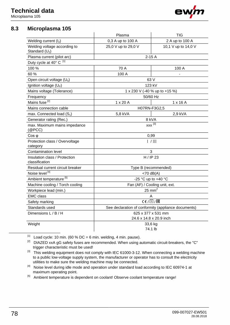
Technical data Microplasma 105
78 099-007027-EW501 28.08.2018
8.3 Microplasma 105 Plasma TIG
Welding current (I2) 0,3 A up to 100 A 2 A up to 100 A
Welding voltage according to
Standard (U2)
25,0 V up to 29,0 V 10,1 V up to 14,0 V
Plasma current (pilot arc) 2-15 A
Duty cycle at 40° C [1]
100 % 70 A 100 A
60 % 100 A -
Open circuit voltage (U0) 63 V
Ignition voltage (UP) 123 kV
Mains voltage (Tolerance) 1 x 230 V (-40 % up to +15 %)
Frequency 50/60 Hz
Mains fuse [2]
1 x 20 A 1 x 16 A
Mains connection cable H07RN-F3G2,5
max. Connected load (S1) 5,8 kVA 2,9 kVA
Generator rating (Rec.) 8 kVA
max. Maximum mains impedance
(@PCC)
xxx [3]
Cos φ 0,99
Protection class / Overvoltage
category Ⅰ / Ⅲ
Contamination level 3
Insulation class / Protection
classification H / IP 23
Residual current circuit breaker Type B (recommended)
Noise level [4]
<70 dB(A)
Ambient temperature [5] -25 °C up to +40 °C
Machine cooling / Torch cooling Fan (AF) / Cooling unit, ext.
Workpiece lead (min.) 25 mm2
EMC class A
Safety marking / /
Standards used See declaration of conformity (appliance documents)
Dimensions L / B / H 625 x 377 x 531 mm
24.6 x 14.8 x 20.9 inch
Weight 33,6 kg
74.1 lb
[1] Load cycle: 10 min. (60 % DC = 6 min. welding, 4 min. pause).
[2] DIAZED xxA gG safety fuses are recommended. When using automatic circuit-breakers, the "C"
trigger characteristic must be used!
[3] This welding equipment does not comply with IEC 61000-3-12. When connecting a welding machine
to a public low-voltage supply system, the manufacturer or operator has to consult the electricity
utilities to make sure the welding machine may be connected.
[4] Noise level during idle mode and operation under standard load according to IEC 60974-1 at
maximum operating point.
[5] Ambient temperature is dependent on coolant! Observe coolant temperature range!

Accessories Welding torch cooling system
099-007027-EW501 28.08.2018 79
9 Accessories Performance-dependent accessories like torches, workpiece leads, electrode holders or
intermediate hose packages are available from your authorised dealer.
9.1 Welding torch cooling system Type Designation Item no.
Cool 50 MPW50 Cooling module with centrifugal pump 090-008818-00502
KF 23E-10, -10 Coolant (-10 °C), 9,3 l 094-000530-00000
KF 23E-200, -10 Coolant (-10 °C), 200 l 094-000530-00001
Type Designation Item no.
RK1 Reverse cooling unit 094-002283-00000
UKV4SET 4M Hose connection set 092-000587-00000
DKF10 Deionised coolant, no frost protection 094-001504-00000
9.2 Transport systems Type Designation Item no.
Trolly 55-6 DF Transport cart, assembled 090-008826-00000
9.3 Option
Type Designation Item no.
ON Filter 355/405/505/50 Contamination filter for air inlet 092-002698-00000
ON TC 55 Tool box for mounting to Trolly 55-5/6 092-002899-00000
ON WAK xx5 Wheel assembly kit for the xx5 machine series 092-001356-00000
9.4 General accessories Type Designation Item no.
Maxex AR/MIX 200bar 30m³
G1/4"
Pressure regulator 096-000000-00000
Maxex Hydrogen 200bar 30m³
G3/8"L
Pressure regulator 096-000001-00000
2M-G1/4"+G3/8"/DIN EN 559 Gas tube, 2 m 092-000525-00001
GH 2X1/4'' 2M Gas hose 094-000010-00001
9.5 Remote controls and accessories Type Designation Item no.
RTF1 19POL 5 M Foot-operated remote control current with
connection cable
094-006680-00000
RT1 19POL Remote control current 090-008097-00000
RTG1 19POL 10m Remote control, current 090-008106-00010
RTP1 19POL Remote control spot welding / pulses 090-008098-00000
9.5.1 Connection and extension cables
Type Designation Item no.
RA5 19POL 5m Connection cable, e.g. for remote control 092-001470-00005
RA10 19POL 10m Remote control e.g. connection cable 092-001470-00010
RA20 19POL 20m Remote control e.g. connection cable 092-001470-00020

Appendix A Parameter overview – setting ranges
80 099-007027-EW501 28.08.2018
10 Appendix A
10.1 Parameter overview – setting ranges
Name Display Setting range
Co
de
Sta
nd
ard
Un
it
min
.
ma
x.
Main current AMP, depending on power source
- A - - -
Gas pre-flow time
0,5 s 0 - 20
Ignition current, percentage of AMP
20 % 1 - 200
Ignition current, absolute, depending on power source
- A - - -
Start time
0,01 s 0,01 - 20,0
Up-slope time
1,0 s 0,0 - 20,0
Pulse current
140 % 1 200
Pulse time
0,01 s 0,00 - 20,0
Slope time (time from main current AMP to secondary current
AMP%)
0,00 s 0,00 - 20,0
Secondary current, percentage of AMP
50 % 1 200
Secondary current, absolute, depending on power source
- A - -
Pulse pause time
0,01 s 0,00 - 20,0
Slope time (time from main current AMP to secondary current
AMP%)
0,00 s 0,00 - 20,0
Down-slope time
1,0 s 0,0 - 20,0
End current, percentage of AMP
20 % 1 - 200
End current, absolute, depending on power source
- A - - -
End current time
0,01 s 0,01 - 20,0
Gas post-flow time
8 s 0,0 - 40,0
Electrode diameter, metric
2,4 mm 1,0 - 4,0
Electrode diameter, imperial
92 mil 40 - 160
spotArc time
2 s 0,01 - 20,0
spotmatic time ( >)
200 ms 5 - 999
spotmatic time ( >)
2 s 0,01 - 20,0
Pulse balance
50 % 1 - 99
Pulse frequency
50 Hz 5 - 15000

Appendix B Searching for a dealer
099-007027-EW501 28.08.2018 81
11 Appendix B
11.1 Searching for a dealer Sales & service parteners
www.ewm-group.com/en/specialist-dealers
"More than 400 EWM sales partners worldwide"