microprocessor-based reverse osmosis...
TRANSCRIPT

LAKEWOOD INSTRUMENTS
MODEL 2450
MICROPROCESSOR-BASED REVERSE OSMOSIS MONITOR
INSTALLATION & OPERATION MANUAL
SERIAL #: _______________
Lakewood Instruments 7838 North Faulkner Road, Milwaukee, Wisconsin 53224 USA Phone (800) 228-0839 • Fax (414) 355-3508 h t t p : / / w w w . l a k e w o o d i n s t r u m e n t s . c o m


IMPORTANT NOTICE
CAUTION: CHEMICAL FEED
All electromechanical devices are subject to failure from a variety of causes. These include mechanical stress, component degradation, electromagnetic fields, mishandling, improper setup, physical abuse, chemical abuse, improper installation, improper power feeds and exposure. While every precaution is taken to insure proper functioning, extra precautions should be taken to limit the ability of over-feeding by limiting chemical quantities available, secondary shut-downs, alarms and redundancy or other available methods.
CAUTION: POWER SOURCE AND WIRING
Low voltage wiring and high voltage (110 plus) should not be run in the same conduit. Always run separately. Even shielded low voltage is not a guarantee of isolation. Every precaution should be taken to insure proper grounding and elimination of shorting or Electromagnetic field (EMF) interference.


Lakewood Instruments
We thank you for your selection and purchase of a Lakewood Instruments product. With proper care and maintenance, this device should give you many years of trouble-free service. Please take the time to read and understand this Installation and Operation Manual, paying special attention to the sections on OPERATION and MAINTENANCE. If, in the future, any parts or repairs are required, we strongly recommend that only original replacement parts be used. Our Customer Service Department is happy to assist you with your parts or service requests.
Lakewood Instruments Customer Service and Technical Support Departments can be reached by calling (800) 228-0839 or faxing (414) 355-3508, Monday through Friday, 7:30 a.m. - 5:00 p.m. CST.
Mail should be sent to:
Lakewood Instruments
7838 North Faulkner Road Milwaukee, WI 53224 USA
1

2

MODEL 2450
Table of Contents INTRODUCTION 5 LONWORKS® Technology 5 Benefits, Features, Specifications 6 Ordering Information 7 Front Panel Description 8 INSTALLATION 9 Checking 9 Mounting 9 Outline and Dimensions 9 Plumbing 10 pH/ORP Probe Installation 10 Conductivity Probe Installation 10 Wiring 11 SETUP AND CALIBRATION 12 Check the Operation 12 Reinitialization 12 Set Up Conductivity Preamp Settings & Temperature Compensation 13 Testing 14 Calibration 14 pH/ORP, Conductivity, Temperature Setpoints 15 Security Levels 16 TECHNICIAN LEVEL MENUS 17 Operation 18 Relays 21 Alarms 22 Flow Meters 23 4-20 mA Outputs 24
System Setup 25 Clock 29 SECURITY LEVEL MENUS 30 LONWORKS is a registered trademark of Echelon Corp.
3

OPERATOR/VIEW LEVEL MENUS 31 MAINTENANCE AND TECHNICAL SERVICE 32 Technical Service/Return Material Procedure 32 Parts List and Service Guide 33 Troubleshooting 34 DRAWINGS 38
4

INTRODUCTION
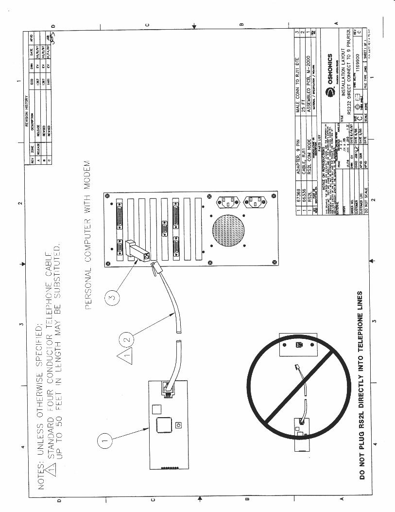
The Model 2450 is a monitoring instrument for Reverse Osmosis machines and can be used for pH/ORP control. The unit provides for tracking of pH, ORP, and conductivity as well as flow monitoring. The system allows for alarm set points and can do a system shutdown when safety set points are exceeded. Refer to the Table of Contents to find more information about alarm and display features. The system can also be set up to communicate with a computer by either a direct RS232 connection or remotely by modem. System operating information such as alarms and measurement readings can be saved to a data log and downloaded to a computer. Security features allow you to select full access to programming features or to restrict to limited or no access.
LONWORKS Technology The Model 2450 is a LONWORKS® Technology based Monitor. LONWORKS Technology gives you a high level of flexibility. The Model 2450 is user-friendly with a graphical screen and numeric keypad, accesses multiple inputs, and sets up easily. This Monitor can also be quickly upgraded in the field. It’s a combination of reliability, accuracy, security and simplicity. • COMMUNICATION ⎯ Setting and reading the Monitor can be done remotely with
the -RS2L computer option. This data link can connect directly to a personal computer (PC) or through a modem and phone line to any modem-equipped PC.
• SECURITY ⎯ A password system can be established which requires a user
password to be able to make changes or do anything more than just read the Monitor readout. An operator password can help ensure that only authorized personnel will operate the system.
5

INTRODUCTION
Benefits, Features, Specifications
BENEFITS The Model 2450 uses LONWORKS® Technology that is the latest in microprocessor capability, giving the user the highest level of application flexibility. A large illuminated graphics screen, multiple inputs and very easy setup with easy field upgrade characterize this new technology. Water meters and sensors are purchased separately.
• System run timer
Figure 1: Model 2450
Reverse Osmosis Monitor
FEATURES • Uses 2-electrode conductivity sensor with ¾ MNPT
process connection • Uses differential pH sensor with ¾ MNPT process
connection. pH input can be configured for ORP sensor.
• Two water meter inputs for Permeate and Concentrate flow rates.
• RS232 output for remote monitoring, control and data acquisition (-RS2L).
• Input for CIP lockout. • Includes Real Time Clock (-RTC).
• 5 Count down timers Lubrication interval Check CIP Check Filters Check Membranes Check Sensor
• Four relays have user-selectable options: pH/ORP setpoint; conductivity setpoint; temperature setpoint permeate flow setpoint; concentrate flow setpoint; percent recovery setpoint; various alarms.
• 4-20 mA output for (-35L, select any four): pH/ORP conductivity temperature concentrate flow permeate flow percent recovery
SPECIFICATIONS
Inputs Power 80-300 VAC Sensor 2 or 4-electrode Conductivity pH or ORP differential Temperature comp. None, 500 NTC,
4K NTC CIP switch Dry contact Water Meter Inputs Two, open collector type. Outputs Relays 3 Amps @ 120 VAC 4-20 mA Two, isolated w/-35L RS232 Requires Windows based PC
w/-RTC-RS2L
Monitor pH Range 0-14 pH pH Accuracy ± 0.05 pH pH Resolution 0.01 pH ORP Range -1000 to +1000 mV ORP Accuracy ± 5 mV ORP Resolution 1 mV Conductivity Range 0-100 or 0-1000 (with proper sensor) Conductivity Accuracy ±1 or ±10 µS (with proper sensor) Conductivity Resolution 1 or 10 µS (with proper sensor) Deadband Adjustable Setpoints Direct or Reverse (configurable in
the field) Keypad Numeric Display Illuminated 128x64 pixel LCD Ambient Temperature 32-158°F (0-70°C) Enclosure ABS Plastic
6

INTRODUCTION
Ordering Information
Figure 2: Model 2450 Installation Schematic
2450 LONWORKS Technology-based Reverse Osmosis Monitor. MONITOR OPTIONS (select no more than two, two -35L may be purchased) -35L Two 4-20 mA outputs (two -35L cards may be used for up to 4 outputs). -RS2L Communications node with the LRWS program.
SENSOR OPTIONS 1104593 pH High Purity sensor, ¼ inch NPT flow cell 520-4-7I-10-STD pH sensor 0-14 pH, ¾ inch NPT 530-4-7I-10 ORP sensor, ¾ inch NPT 540K0.1-4-10I-10-TC 500 Conductivity Sensor 0-10 µS, ¾ inch NPT 540K.1-4-10I-10-TC 500 Conductivity Sensor 0-100 µS, ¾ inch NPT 543-L-4-8I-10-STD Conductivity Sensor 0-1000 µS, 1 inch NPT 543-M-4-8I-10-STD Conductivity Sensor 500-100,000 µS, 1 inch NPT AUTOTROL TURBINE WATER METER OPTIONS 1TM-NPT 1 inch turbine water meter with brass pipe thread adapters. 1TM-ESW 1 inch turbine water meter with PVC solvent weld adapters. 2TM-NPT 2 inch turbine water meter with brass pipe thread adapters. 2TM-ESW 2 inch turbine water meter with PVC solvent weld adapters. 49C25 25 ft cable for turbine meters. 49C50 50 ft cable for turbine meters. SOFTWARE AND EXTERNAL MODEM OPTIONS LRWS Windows-based registered software for computer to communicate with 2000 Series Controllers. MD4X High-Baud modem in NEMA-4 enclosure ready to power. MD High-Baud modem for use with 2000 Series Controllers.
7

INTRODUCTION
Front Panel Description
LCD A large, 128x64 pixel graphic display makes it easy to read the menu-driven
program.
Figure 3: Model 2450 Front Panel with Display
ENCLOSURE A sturdy enclosure protects your Monitor. Make sure it is properly mounted (See: INSTALLATION; Mounting). The weatherproof enclosure provides NEMA protection. The Monitor does not have outlets or a power cord and must be hardwired through ½ inch conduit knockouts.
16-BUTTON KEYPAD ENT = for Menu selection and/or
acceptance of selected values.
CLR = to exit a Menu selection and/or skip input options.
PRO = to program a Menu selection.
LOCK SCREW The lock screw keeps your circuit boards secure and provides easy access for wiring and setup. Simply turn the lock screw and pull open the front panel.
8

INSTALLATION
Checking
Inspect the shipping carton for obvious external damage. Note on the carrier's bill-of-lading the extent of the damage, if any, and notify the carrier. Save the shipping carton until your Model 2450 Monitor is started up.
If shipping damage has occurred, call the Customer Service Department for Lakewood Instruments at (800) 228-0839 and return the Monitor to the factory in the original carton.
Mounting
Model 2450 Monitors are typically panel-mounted, but they can be mounted on a FLAT, NON-VIBRATING wall.
Outline and Dimensions
Figure 4: Model 2450 Enclosure Dimensions
INSTALLATION NOTES: • Install on smooth surface to
prevent stress on mounting feet. • Do not install on vibrating wall. • If enclosure is installed in
corrosive environments, consider purging.
• Dimensions indicated as inches (millimeters).
• Material: Body—PVC; Bevel—ABS.
• Use either #6 or #10 mounting screws (4).
9

INSTALLATION
Plumbing
If you have questions or need assistance, call the Customer Service
Department for Lakewood Instruments (800) 228-0839, or fax (414) 355-3508, Monday-Friday, and 7:30 a.m. - 5:00 p.m. CST. pH/ORP Probe Installation The pH/ORP sensor should be mounted vertically with the glass bulb facing down. It may be mounted at an angle as long as it is no more than 75° from the vertical position (see DWG #04258 in the back of this manual). Due to the bubble position, however, the preferred mounting angle is no more than 45° from vertical. WARNING: THE SENSOR MUST ALSO BE MOUNTED IN A LOCATION SO THAT IT IS ALWAYS WET. IF IS LOCATED IN A PIPE OR TANK WITH VARIABLE FLUID LEVELS, IT IS IMPORTANT THAT THE SENSOR IS INSTALLED WHERE IT CAN REMAIN WET. FAILURE TO DO SO WILL DAMAGE THE SENSOR. Conductivity Probe Installation The Conductivity sensor may be mounted in any position as long as water is always in contact when measuring process water. Avoid connections in “dead leg” sections of pipe. An air pocket around the electrode tips will cause erroneous readings. The sensor electrodes should be in direct contact with the process flow (see DWG #04259 in the back of this manual). Write your other plumbing installation notes here:
10

INSTALLATION
Wiring
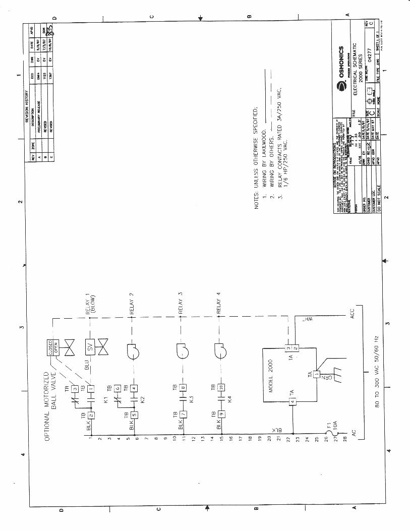
The Model 2450 Monitor is equipped with a terminal block inside and three (3) conduit locations at the bottom of the enclosure. It has internal relays suitable for motor loads up to 1/6 horsepower.
If you need more current capacity, contact the Customer Service Department for Lakewood Instruments and order the HR box with 25-Amp rated interposing relays. Make sure the circuit is not operative while connections are being made. Double-check for proper grounding. DO NOT install sensor wires in the same conduit with 115/230 VAC or power wiring. Doing so is not safe and results in inaccurate control. It is usually a violation of electrical codes as well.
The Model 2450 Monitor can operate on a wide range of AC voltage without need for internal changes. The circuit breaker in the power circuit to the Monitor should be sized to handle the combination of all the loads connected to the Monitor. The Model 2450 by itself will use less than 1 Amp of current. If 230 VAC is used, be sure the motorized valve and other controlled devices are also rated at 230 VAC.
Install conduit and fittings in the knockouts provided in the bottom of the enclosure. Access the power terminals by opening the cover and loosening the lock screw on the left side of the panel. Be sure to connect the green ground wire to the TA lug #1 (also marked "EARTH GROUND") on the grounding plate. The white neutral wire goes to TA#2 or TA#3 (both also marked "NEUTRAL").
Power wiring and signal wiring (low voltage) such as sensor wires MUST NOT occupy the same conduit. Connect low-voltage wiring according to DWG #69506. It is also recommended that you install seal-off compound in the conduit fitting at the Monitor end of the sensor conduit and a small vent hole to the outside to protect the Monitor from damage in the instance of sensor damage and leakage. WARNING: DO NOT PLUG IN CHEMICAL PUMPS THAT ARE LARGER THAN 1/6 HORSEPOWER. THE CONTROL RELAYS ARE INTENDED FOR ELECTRONIC OR SMALL MOTOR-DRIVEN CHEMICAL PUMPS. LARGER PUMPS REQUIRE THE -HR OPTION WITH 25-AMP-RATED INTERPOSING RELAYS. CONTACT THE CUSTOMER SERVICE DEPARTMENT FOR LAKEWOOD INSTRUMENTS FOR SPECIAL INSTRUCTIONS. Write your wiring installation notes here:
11

SETUP AND CALIBRATION
Check the Operation
After installation is completed, follow these instructions: • Make sure the Monitor has power and is operating.
You will notice the Monitor will display:
This indicates that power has been applied to the Monitor and no one has touched the keypad. This will also happen anytime there is a power outage and power has been returned to the Monitor.
SERIES 2000 REVERSE OSMOSIS
MONITOR
PRESS ANY KEY
• Press any key on the keypad and you will see the Display Process Screen on
the screen. • Press CLR on the keypad and you will see the Main Menu on the screen. • Use the and arrow keys to move through the menu.
Reinitialization
It is suggested that you reinitialize the Monitor before programming in your own numbers. This will wipe out any random settings which may be in the Monitor. To do so, follow these instructions: • After you have practiced moving up and down in the Main Menu, press 6 or
highlight SYSTEM SETUP and press ENT. • Press 2 or highlight INITIALIZATION and press ENT. • Press 2 or highlight WHOLE MONITOR and press ENT. A warning will
appear on the screen, advising you that "this option requires re-calibration and re-programming!" Press 1 to proceed, 2 to cancel.
12

SETUP AND CALIBRATION
Set Up Conductivity Preamp Settings & Temperature Compensation Prior to testing your Monitor, set up the internal conductivity preamp for the sensor you are using. If you purchased a sensor with your Monitor, the preamp will already be set up by the factory and you can proceed directly to testing (next page). If you change the sensor used and do not verify the preamp set up for your attached sensor, the conductivity readings may be erroneous. Set up the preamp by following these instructions: • From the SYSTEM SETUP menu, Press 1 or highlight PROCESS
PARAMETERS and press ENT. The WHICH PROCESS? menu will be displayed.
• Press 2 or highlight COND and press ENT. The CONDUCTIVITY menu will be displayed.
• Press 2 or highlight PREAMP SETUP and press ENT. The COND PREAMP SETUP menu will be displayed, showing the current voltage gain, sample resistor, and drive frequency values. Use the and arrow keys to change each displayed value to the one appropriate for your sensor (see table below). Press ENT when each correct value has been entered and displayed.
• You will automatically be returned to the CONDUCTIVITY menu. Press 3 or highlight CELL CONSTANT and press ENT.
• Use the numeric keypad to enter the appropriate cell constant for your sensor (see table below). Press ENT when the correct value is displayed.
• After pressing ENT, you will be returned to the CONDUCTIVITY menu. Press CLR to return to the WHICH PROCESS? menu.
• Press 3 or highlight TEMP and press ENT. The TEMPERATURE menu will be displayed.
• Press 2 or highlight TEMP COMPENSATION and press ENT. The TEMP COMPENSATION menu will be displayed.
• Press the option number or highlight the correct value for your sensor and press ENT. The new stored value will be displayed, along with the message “PRESS ANY KEY”. Press any key to confirm this value.
• Finally, press CLR three times to return to the MAIN MENU. Your preamp is now set up for your attached conductivity sensor.
AMPLIFIER SETTINGS IN THE MODEL 2450
Sensor Range (µS)
Gain Sample Resistor
Drive Freq (Hz)
Temp Comp (NTC)
Cell Const
540K.01 2 Elec 0-10 10 2000 500 500 0.01 540K.1 2 Elec 0-10 1 2000 30 500 0.1 540K.1 2 Elec 0-100 10 2000 500 500 0.1 543L 4 Elec 0-100 10 200 500 4K 0.03 543L 4 Elec 0-1,000 10 200 500 4K 0.03 543M 4 Elec 0-1,000 10 200 500 4K 0.38 543M 4 Elec 0-2,500 10 20 500 4K 0.38
13

SETUP AND CALIBRATION
Testing
Continue to test the Monitor's accessories by following these instructions: • Get back to the MAIN MENU. • Press 1 or highlight OPERATION and press ENT. There may be a dark
flashing line separating the two sections; this indicates which alarms are active at the moment. As shown at the bottom of the screen, press ENT to access the relays.
• The four relays line up vertically with boxes that are blank when the relay is not in operation. Select a relay by pressing its number. The box will change (probably it will become shaded), indicating that the relay has reversed its status from OFF to ON. Each time you press the number, the relay reverses its status.
• NOTE that relays retain manual mode even after powering down. • Finally, press CLR twice to return to the MAIN MENU.
Calibration
Calibration Methodology 1. You must have an accurate reading of the system water to properly calibrate the
Monitor. • A properly calibrated hand-held temperature, conductivity, pH, or ORP meter
may be acceptable for completing calibrations. • NOTE: if at any time you believe that the pH, ORP, conductivity, or
temperature calibrations have been improperly performed, you may re-initialize the calibrations and restore them to their default values.
2. Calibrate the temperature first: • Measure the temperature of the system water. • Press PRO on the keypad, select ZERO. • Use the number keys to enter the value, then press ENT. • Do not choose SPAN when calibrating temperature.
3. To calibrate the pH/ORP: • Measure the pH/ORP of the system water with a hand-held meter. • Press PRO on the keypad, select ZERO. • Use the number keys to enter the value, then press ENT. • Do not choose SPAN when calibrating pH/ORP.
4. To calibrate conductivity: • Take a system water sample reading with your hand-held meter. • Press PRO on the keypad. • Use the number keys to enter the value, then press ENT. • When the number is accepted, you will see the SPAN COMPLETE screen
before the LCD display switches back to the original OPERATION screen. 5. Take a second sample with and confirm that the readings on the Monitor display
are correct.
14

SETUP AND CALIBRATION
Setpoints (pH/ORP, Conductivity, Temperature, Permeate & Concentrate Flow)
1. Typically, pH/ORP is the only process that will be controlled. 2. Follow these instructions to establish the Monitor's setpoint:
• From the MAIN MENU, press 2 or highlight RELAYS and press ENT. • Press the number of the relay governing the operation you wish to control. • Press 2 or highlight SETPOINT CONTROL and press ENT. • Select process to control (pH/ORP, conductivity, etc.) by pressing its number.
3. Press 1 to enter SETPOINT values for that relay. Simply use the keypad numbers to enter the proper value and press ENT. When finished, you will automatically be moved down to the next setpoint value. a) Enter SETPOINT value b) Enter DEADBAND value
“Deadband" refers to a range above and below the setpoint within which the Monitor will not react. Using a deadband range reduces the chances of erroneous or nuisance relay activity due to temporary fluctuations in monitored levels. It should be a small percentage of the setpoint. Half the deadband amount will automatically be put above the setpoint, and the other half below. For example, a pH setpoint of 7.00 pH units in DIRECT mode, with a deadband of .10 pH units, would result in a system that turns the relay ON at 7.05 and OFF at 6.95 pH. The same setpoint in REVERSE mode would turn the relay ON at 6.95 and OFF at 7.05 pH units.
c) Enter TIMEOUT value d) Maximum 17 hours 59 minutes.
4. Press 2 to enter SETPOINT directions a) Press 1 to enable DIRECT control (The relay opens below setpoint, e.g., relay
controlling acid injection for pH control. That is, when pH rises above the setpoint, the relay closes and allows injection of more acid.)
b) Press 2 to enable REVERSE control (The relay opens above setpoint, e.g., relay controlling caustic injection for pH control. That is, when pH falls below the setpoint, the relay closes and allows injection of more caustic.)
5. When finished with all setpoint entries, you can press CLR 3 times to select another relay, or, press CLR 4 times to return to the MAIN MENU.
15

SETUP AND CALIBRATION
Security Levels The Model 2450 Monitor is menu-driven for easy use. Once you become familiar with the menu options, it will be easy to perform setup and calibration procedures. This section of the manual provides a comprehensive overview of the entire menu as it can be viewed from each security level. In order to lead off with a complete look at the menu, the levels will be shown in the following order: 3) TECHNICIAN, 2) OPERATOR and 1) VIEW ONLY. Once you review the instructions in this section and learn the menu options, you will be able to perform your own setup and calibration using these examples to guide you through the process. The Model 2450 offers three (3) optional security levels: 1) VIEW ONLY, 2) OPERATOR and 3) TECHNICIAN. A password is required to change from one security level to another. Each level has its own factory-preset password (2222 for TECHNICIAN, 1111 for OPERATOR), but your water treatment engineer can also designate personalized passwords from the TECHNICIAN Level Menu. NOTE: IF YOU USE PERSONALIZED PASSWORDS, MAKE SURE THEY ARE RECORDED IN A SAFE AND SECURE PLACE.
The following pages illustrate the menu screens available in each security level:
16

TECHNICIAN LEVEL MENUS
The complete MAIN MENU has seven (7) available options that can be accessed in the TECHNICIAN Level. Use the and keys to scroll through the options. The TECHNICIAN Level allows you to review the entire MAIN MENU. As an introduction, here is a graphic overview of the first level of each option in the MAIN MENU to see how it operates. Complete detail of each option is provided on the following pages.
MAIN MENU =============
1 OPERATION 2 RELAYS 3 ALARMS 4 FLOW METERS 5 4-20 MA OUTPUTS 6 SYSTEM SETUP 7 CLOCK
1
PERM CONC
0 0 {Alarms Flashing}
pH COND
5.76 90
PRO: CALIB; ENT=RELAYS
2
WHICH RELAY? ============
1 RLY1 2 RLY2 3 RLY3 4 RLY4
3
WHICH INPUT DEVICE?
============ 1 pH/ORP 2 COND 3 TEMP 4 PERM 5 CONC 6. FEED 7. % REC
4
WHICH INPUT DEVICE?
============ 1 PERM 2 CONC 3. FEED
6
SYSTEM SETUP ============
1 PROCESS PARAMETERS 2 INITIALIZATION 3 SECURITY 4 SOFTWARE VERSION 5 TIMER 6 DIAGNOSTICS 7 COMMUNICATIONS
7
WED 28 AUG 96
05:42:40
PRO: CHANGE; CLR=EXIT
NOTE: Press CLR to return to a previous screen. Repeated use of CLR allows you to return all the way back to the MAIN MENU from anywhere in the program.
17

TECHNICIAN LEVEL MENUS
OPERATION
MAIN MENU
============= 1 OPERATION 2 RELAYS 3 ALARMS 4 FLOW METERS 5 4-20 MA OUTPUTS 6 SYSTEM SETUP 7 CLOCK
The OPERATION menu allows you to do the following: 1) View current status of a) pH/ORP, b) conductivity, c) concentrate
flow and d) permeate flow 2) Use PRO to calibrate the Monitor 3) Use ENT to manually control output relays
Current permeate flow in GPM, LPM or cubic meters/hour.
Press ENT or 1 to view OPERATION
Current reading of pH/ORP.
NOTE: ZERO shifts the offset and SPAN adjusts the slope (see below).
CALIBRATION ============
1 ZERO 2 SPAN
CALIBRATION
4.01 pH
PRO: “+/-“; ENT=ACCEPT
PERM CONC 0 0
{ALARMS FLASHING} pH COND 5.76 90
PRO: CALIB; ENT=RELAYS
Press PRO to calibrate your Model 2450.
WHICH INPUT DEVICE?
============ 1 pH 2 COND 3 TEMP
CALIBRATION
COMPLETE
Current concentrate flow in GPM, LPM or cubic meters/hour.
Current conductivity in µS.
CALIBRATION
90 µS
PRO: “+/-“; ENT=ACCEPT
CALIBRATION
25 ºC
PRO: “+/-“; ENT=ACCEPT
Press CLR to return to a previous screen. Repeated use of CLR allows you to return to the MAIN MENU from anywhere in the program.
18

TECHNICIAN LEVEL MENUS
OPERATION
PERM CONC 0 0
{ALARMS FLASHING} pH COND 5.76 90
PRO: CALIB; ENT=RELAYS
Press ENT to access relays.
This screen shows you the current status of the four relays. Simply press the number of the relay if you want to manually change a relay’s status.
RELAY AUTO-MANUAL (5 MINS.) (1) RLY1 MANUAL
(2) RLY2
(3) RLY3
(4) RLY4
PRESS 1-4; CLR=EXIT
Press CLR to return to the OPERATION menu.
Press CLR to return to a previous screen. Repeated use of CLR allows you to return to the MAIN MENU from anywhere in the program.
19

TECHNICIAN LEVEL MENUS
OPERATION
PERM CONC
0 0 {ALARMS FLASHING}
pH COND
5.76 90
PRO: CALIB; ENT=RELAYS
RO MACHINE RUN TIME
0:00 {ALARMS FLASHING}
TEMP = 25 ºC
PRO=CALIB; ENT=RELAYS
From the main operation screen, press the or keys to scroll through these other screens:
PERM CONC 0.0 0.0
{ALARMS FLASHING}
COND %REC 0.0 0 %
PRO: CALIB; ENT=RELAYS
µS 89 {ALARMS FLASHING}
PERM 0 GPM
PRO=CALIB; ENT=RELAYS
pH 5.58 {ALARMS FLASHING}
FEED 0 GPM
PRO=CALIB; ENT=RELAYS
TOTAL PERM= 0
{ALARMS FLASHING} TOTAL FEED=
0PRO=CALIB; ENT=RELAYS
RLY1 RLY2 RLY3 RLY4
{ALARMS FLASHING}
28 AUG ‘96 14:09:07
PRO=CALIB; ENT=RELAYS
Press CLR to return to a previous screen. Repeated use of CLR allows you to return to the MAIN MENU from anywhere in the program.
RELAYS
20

TECHNICIAN LEVEL MENUS
MAIN MENU
============= 1 OPERATION 2 RELAYS 3 ALARMS 4 FLOW METERS 5 4-20 MA OUTPUTS 6 SYSTEM SETUP 7 CLOCK
Press ENT or 2 to view RELAYS
Pressing 1 will disable the relay chosen. SETPOINT OPTIONS
=========== 1 SETPOINT VALUES 2 SETPOINT DIRECTION
SETPOINT= 0 µS
DEADBAND=
0 µS PRO: “+/-“; ENT: ACCEPT
RLY1 and 2 measure flow in LPM; RLY3 measures conductivity in µS or total dissolved solids in ppm; RLY4 measures pH.
TIMEOUT=
0:00 MAX: 17 HOURS 59 MINS
PRO: “+/-“; ENT: ACCEPT
WHICH RELAY?
========== 1 RLY1 2 RLY2 3 RLY3 4 RLY4
RELAY OPTIONS
========== 1 DISABLED 2 SETPOINT CONTROL 3 MIN PER DURATION 4 ALARM RELAY 5 CHANGE MY NAME 6 CIP LOCKOUT
OLD NAME= RLY1
NEW NAME=
RLY1 <UP><DOWN> ENT: ACCEPT
Use the and keys to scroll through letters. Press ENT to accept the letter.
MINS:SECS RELAY IS ON 0:00
OVER WHAT DURATION? 0:00
MAX: 17 HOURS 59 MINS PRO: +/- ENT:ACCEPT
WHICH ALARMS? ============
1 pH: HIGH ALARM 2 pH: LOW ALARM 3 COND: HIGH ALARM 4 TEMP: HIGH ALARM 5 PERM: HIGH ALARM 6 PERM: LOW ALARM 7 FEED: HIGH ALARM 8 FEED: LOW ALARM 9 % REC: HIGH ALARM 10 LUBRUCATION INTERN 11 CHECK CIP 12 CHECK FILTERS 13 CHECK MEMBRANES 14 CHECK SENSOR 15 COND: FOULED SENSOR 16 SHORTED TC 17 OPEN TC 18 pH : HI REF IMPED 19 pH: BROKEN GLASS 20 pH: HI REF VOLT 21 pH: LOW REF VOLT 22 CIP SWITCH CLOSED 23 RLY 1: TIME EXC 24 RLY 2: TIME EXC 25 RLY 3 : TIME EXC 26 RLY 4: TIME EXC
Use the and keys to scroll through the menu. Press ENT to toggle alarms.
SETPOINT DIRECTION ===========
1 DIRECT 2 REVERSE
Pressing either 1 or 2 will switch the setpoint direction to DIRECT or REVERSE.
WHICH INPUT DEVICE? ==========
1 pH 2 COND 3 TEMP 4 PERM 5 CONC 6 FEED 7 % REC
Press CLR to return to a previous screen. Repeated use of CLR allows you to return to the MAIN MENU from anywhere in the program.
21

TECHNICIAN LEVEL MENUS
ALARMS
MAIN MENU
============= 1 OPERATION 2 RELAYS 3 ALARMS 4 FLOW METERS 5 4-20 MA OUTPUTS 6 SYSTEM SETUP 7 CLOCK
Press ENT or 3 to view ALARMS
1—pH/ORP
HIGH ALARM= 10.00 pH
LOW ALARM=
4.00 pH PRO: “+/-“ ENT: ACCEPT
2—COND
HIGH ALARM=
4000 µS
PRO: “+/-“ ENT: ACCEPT
3—TEMP
HIGH ALARM=
99 °C
PRO: “+/-“ ENT: ACCEPT
WHICH INPUT DEVICE?
========== 1 pH 2 COND 3 TEMP 4 PERM 5 CONC 6 FEED 7 % REC
Concentrate does not have high/low alarms associated with it.
4—PERM
HIGH ALARM= 5000 GPM
LOW ALARM=
10 GPM
PRO: “+/-“ ENT: ACCEPT
6-FEED
HIGH ALARM= 5000 GPM
LOW ALARM=
10 GPM
PRO: “+/-“ ENT: ACCEPT
7--% REC
HIGH ALARM= 100%
PRO: “+/-“ ENT: ACCEPT
Pressing ENT to accept from any of these secondary menus will return you to the WHICH INPUT DEVICE menu.
Press CLR to return to a previous screen. Repeated use of CLR allows you to return to the MAIN MENU from anywhere in the program.
22

TECHNICIAN LEVEL MENUS
FLOW METERS
MAIN MENU
============= 1 OPERATION 2 RELAYS 3 ALARMS 4 FLOW METERS 5 4-20 MA OUTPUTS 6 SYSTEM SETUP 7 CLOCK
Press ENT or 4 to view FLOW METERS
1—DATA INDUSTRIAL
PERM SLOPE VALUE (K) =
0.0000 OFFSET = 0.0000
PRO: “+/-“ ENT:ACCEPT
PERM
SLOPE VALUE (K) = 0.0000
RESET TOTAL COUNT? 1 YES 2 NO
2—SIGNET
PERM K-FACTOR =
00.00
PRO: “+/-“ ENT:ACCEPT
PERM
K-FACTOR = 000.000
RESET TOTAL COUNT? 1 YES 2 NO
WHICH INPUT DEVICE?
========== 1 PERM 2 CONC 3 FEED
WATER METER TYPES ==========
1 DATA INDUSTRIAL 2 SIGNET 3 AUTOTROL TURB 1IN. 4 AUTOTROL TURB 2IN. 5 CHANGE MY NAME
RESET
COMPLETE
5—CHANGE NAME
OLD NAME= PERM
NEW NAME=
PERM <UP><DOWN> ENT: ACCEPT
3—AUTOTROL TURB 1IN. GALLONS OR LITERS
=========== 1 GALLONS 2 LITERS
PERM
AUTOTROL TURB 1IN.
RESET TOTAL COUNT? 1 YES 2 NO
4—AUTOTROL TURB 2IN.
GALLONS OR LITERS ===========
1 GALLONS 2 LITERS
PERM
AUTOTROL TURB 1IN.
RESET TOTAL COUNT? 1 YES 2 NO
NOTE: There may be other options available for these water meters. Call an Application Engineer for more details.
Press CLR to return to a previous screen. Repeated use of CLR allows you to return to the MAIN MENU from anywhere in the program.
23

TECHNICIAN LEVEL MENUS
4-20 mA OUTPUT
MAIN MENU
============= 1 OPERATION 2 RELAYS 3 ALARMS 4 FLOW METERS 5 4-20 MA OUTPUTS 6 SYSTEM SETUP 7 CLOCK
Press ENT or 5 to view 4-20 MA OUTPUTS
4-20 MA OUTPUTS ============
1 SET 4-20 MA RANGE 2 CALIBRATE 4-20 MA 3 MANUAL CONTROL
4 MA VALUE=
00000µS
20 MA VALUE=
05000µS
24
PRO: “+/-“ ENT:ACCEPT
The Monitor will output what it thinks 4 MA is.
Measure the actual output, key in the value and then press ENT.
MILLIAMPS
04.00
PRO: “+/-“ ENT:ACCEPT
MILLIAMPS= 3.98
MILLIAMPS=
20.00
MILLIAMPS= 3.98
MILLIAMPS=
20.15
MANUAL 4-20 MA CONTROL”
4 8 12 16 20 + + + + +
PRO: “+/-“ ENT:ACCEPT
Use the and keys to manually drive the output. The Monitor will output what it thinks 20 MA is. Measure the actual output, key in the value and then press ENT.
Press CLR to return to a previous screen. Repeated use of CLR allows you to return to the MAIN MENU from anywhere in the program.

TECHNICIAN LEVEL MENUS
SYSTEM SETUP
MAIN MENU
============= 1 OPERATION 2 RELAYS 3 ALARMS 4 FLOW METERS 5 4-20 MA OUTPUTS 6 SYSTEM SETUP 7 CLOCK
SYSTEM SETUP =============
1 PROCESS PARAMETERS 2 INITIALIZATION 3 SECURITY 4 SOFTWARE VERSIONS 5 TIMERS 6 DIAGNOSTICS 7 COMMUNICATIONS
SELECT OPTION #1 Process Parameters.
OLD NAME=
pH
NEW NAME= pH
<UP><DOWN> ENT:ACCEPT
OLD NAME=
COND
NEW NAME= COND
<UP><DOWN> ENT:ACCEPT
WHICH PROCESS?
============= 1 pH 2 COND 3 TEMP 4 % REC
OLD NAME=
TEMP
NEW NAME= TEMP
<UP><DOWN> ENT:ACCEPT
OLD NAME= % REC
NEW NAME=
% REC
<UP><DOWN> ENT:ACCEPT
pH =============
1 CHANGE MY NAME 2 STAND-BY MODE 3 CHANGE TO ORP
CHANGE TO ORP =============
1 YES 2 NO
FORCE THE PROCESS
INTO STAND-BY MODE? =============
1 YES 2 NO
After selecting YES, all references to “pH” will be replaced by “ORP”. This same sequence will change ORP back to pH.
STAND-BY VALUE =
7.00 pH
Press CLR to return to a previous screen. Repeated use of CLR allows you to return to the MAIN MENU from anywhere in the program.
25

TECHNICIAN LEVEL MENUS
SYSTEM SETUP
MAIN MENU
============= 1 OPERATION 2 RELAYS 3 ALARMS 4 FLOW METERS 5 4-20 MA OUTPUTS 6 SYSTEM SETUP 7 CLOCK
SYSTEM SETUP =============
1 PROCESS PARAMETERS 2 INITIALIZATION 3 SECURITY 4 SOFTWARE VERSIONS 5 TIMERS 6 DIAGNOSTICS 7 COMMUNICATIONS
INITIALIZATION =============
1 CALIBRATIONS 2 WHOLE MONITOR
SELECT OPTION #2 Initialize the Monitor.
Initialization resets control functions back to the factory default values. The three levels of initialization are as follows:
1) Calibrations—simply resets the process calibrations. 2) Process Parameters 3) Whole Monitor—resets all of the control functions.
If you initialize, all previously programmed settings will be lost and you must go through the proper setup procedures for the areas initialized.
WARNING: THIS OPTION REQUIRES RE-CALIBRATION AND
RE-PROGRAMMING! PROCEED? 1 YES 2 NO
Press CLR to return to a previous screen. Repeated use of CLR allows you to return to the MAIN MENU from anywhere in the program.
26

TECHNICIAN LEVEL MENUS
SYSTEM SETUP
MAIN MENU
============= 1 OPERATION 2 RELAYS 3 ALARMS 4 FLOW METERS 5 4-20 MA OUTPUTS 6 SYSTEM SETUP 7 CLOCK
SELECT OPTION #3 Change the security password. A password is assigned for each security level at the factory. For security reasons, you may desire to routinely change the passwords for the OPERATOR and TECHNICIAN Level Menus. To change a password, select the security level you want to change (i.e., TECHNICIAN), then enter the old password. If the old password is correct, you are asked to assign a new 4-key password. NOTE: Changing the operator password does not put the Monitor into OPERATOR mode. You will need to return the Monitor back into OPERATOR mode for operator use.
SYSTEM SETUP ===============
1 PROCESS PARAMETERS 2 INITIALIZATION 3 SECURITY 4 SOFTWARE VERSIONS 5 DIAGNOSTICS 6 COMMUNICATIONS
CHANGE PASSWORD
=============== 1 OPERATOR 2 TECHNICIAN
OPERATOR
PASSWORDS ARE 4 KEYS ENTER A NEW PASSWORD OLD PASSWORD=**** NEW PASSWORD=**** VERIFY =****
MENU SERIES 1 REV L IO SERIES 1 REV N
SELECT OPTION #4 View the software version information. This option is primarily for use when troubleshooting the Model 2450. The Technical Service Representative for Lakewood Instruments will need to know this information in order to properly diagnose your Monitor.
SELECT OPTION #5 View raw A/D values. This option allows you to view the raw A/D values and may be useful when troubleshooting.
RAW DIGITAL VALUES
C0=000 C4=000 C1=000 C5=000 C2=000 C6=000 C3=000 C7=000
Press CLR to return to a previous screen. Repeated use of CLR allows you to return to the MAIN MENU from anywhere in the program.
27
TECHNICIAN LEVEL MENUS
28
SYSTEM SETUP
MAIN MENU
============= 1 OPERATION 2 RELAYS 3 ALARMS 4 FLOW METERS 5 4-20 MA OUTPUTS 6 SYSTEM SETUP 7 CLOCK
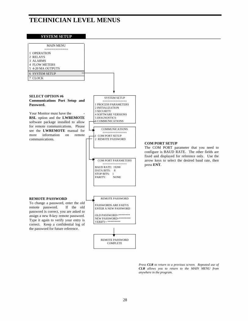
SELECT OPTION #6 Communications Port Setup and Password. Your Monitor must have the -RSL option and the LWREMOTE software package installed to allow for remote communications. Please see the LWREMOTE manual for more information on remote communications. REMOTE PASSWORD To change a password, enter the old remote password. If the old password is correct, you are asked to assign a new 8-key remote password. Type it again to verify your entry is correct. Keep a confidential log of the password for future reference.
SYSTEM SETUP ===============
1 PROCESS PARAMETERS 2 INITIALIZATION 3 SECURITY 4 SOFTWARE VERSIONS 5 DIAGNOSTICS 6 COMMUNICATIONS
COMMUNICATIONS ===============
1 COM PORT SETUP 2 REMOTE PASSWORD
COM PORT PARAMETERS ===============
BAUD RATE: 19200 DATA BITS: 8 STOP BITS: 1 PARITY: NONE
REMOTE PASSWORD
PASSWORDS ARE 8 KEYS ENTER A NEW PASSWORD OLD PASSWORD=******** NEW PASSWORD=******** VERIFY= *********
REMOTE PASSWORD COMPLETE
COM PORT SETUP The COM PORT parameter that you need to configure is BAUD RATE. The other fields are fixed and displayed for reference only. Use the arrow keys to select the desired baud rate, then press ENT.
Press CLR to return to a previous screen. Repeated use of CLR allows you to return to the MAIN MENU from anywhere in the program.

TECHNICIAN LEVEL MENUS
CLOCK
MAIN MENU
============= 1 OPERATION 2 RELAYS 3 ALARMS 4 FLOW METERS 5 4-20 MA OUTPUTS 6 SYSTEM SETUP 7 CLOCK
Press ENT or 7 to view CLOCK
Month/Date/Year
Hour/Minutes/Seconds
WED 03 MAY 1996
00:00:00
PRO: CHANGE; CLR: EXIT
WED 03 MAY 1996
00:00:00
PRO: “+/-“; ENT:: EXIT
Use the and keys to set the day of the week. Then press ENT to move to the next display. Use the keypad numbers to set the correct calendar date. Press ENT to accept the entered value and to move to the next setting. The clock will start counting time after you move through the entire selection and press ENT the last time.
Press CLR to return to a previous screen. Repeated use of CLR allows you to return to the MAIN MENU from anywhere in the program.
29
SECURITY LEVEL MENUS
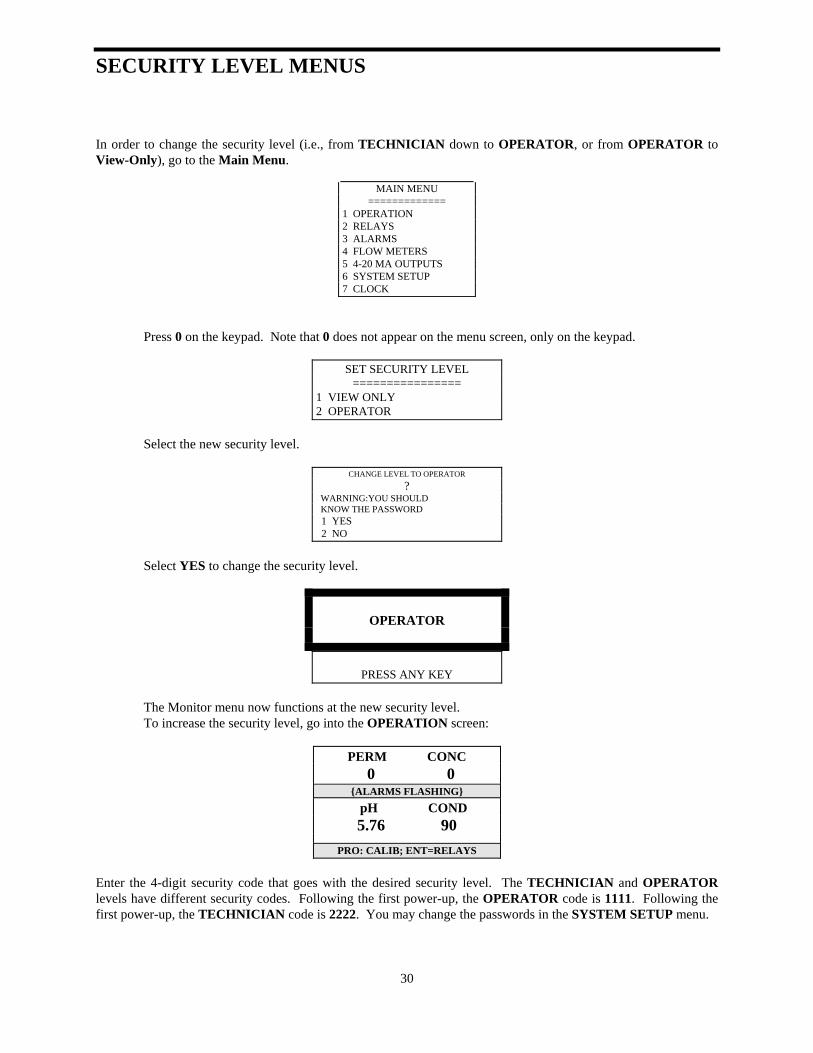
In order to change the security level (i.e., from TECHNICIAN down to OPERATOR, or from OPERATOR to View-Only), go to the Main Menu.
MAIN MENU
============= 1 OPERATION 2 RELAYS 3 ALARMS 4 FLOW METERS 5 4-20 MA OUTPUTS 6 SYSTEM SETUP 7 CLOCK
Press 0 on the keypad. Note that 0 does not appear on the menu screen, only on the keypad.
SET SECURITY LEVEL
================ 1 VIEW ONLY 2 OPERATOR
Select the new security level.
CHANGE LEVEL TO OPERATOR
? WARNING:YOU SHOULD KNOW THE PASSWORD 1 YES 2 NO
Select YES to change the security level.
OPERATOR
PRESS ANY KEY
The Monitor menu now functions at the new security level. To increase the security level, go into the OPERATION screen:
PERM CONC
0 0 {ALARMS FLASHING}
pH COND 5.76 90
PRO: CALIB; ENT=RELAYS
Enter the 4-digit security code that goes with the desired security level. The TECHNICIAN and OPERATOR levels have different security codes. Following the first power-up, the OPERATOR code is 1111. Following the first power-up, the TECHNICIAN code is 2222. You may change the passwords in the SYSTEM SETUP menu.
30

OPERATOR/VIEW LEVEL MENUS
31
The OPERATOR Level Menu allows you limited access to the MANUAL RELAYS and CALIBRATION options. In OPERATION, you can view the current conductivity or TDS level, any alarms and various status lines. You can also perform a calibration as shown below:
Current reading of RO process water conductivity level. This line allows you to view one of six different status lines. To select the status to view, use the and keys to move through the list.
PERM CONC 0 0
{ALARMS FLASHING} pH COND 5.76 90
PRO: CALIB; ENT=RELAYS
Press PRO to calibrate your Model 2450. (Refer to page 16 of this Manual for all calibration screens.)
CALIBRATION
2450 µS
PRO: "+/-"; ENT: ACCEPT
The alarm status line, a darkened area, scrolls through all currently active alarms (see alarms list).
If no alarms are active, nothing will be displayed here.
To perform a calibration, have your water treatment specialist tell you the value you should enter (based on your water sample reading). Press ENT after you have keyed in the proper number. The calibration procedure is described in the TECHNICIAN Level Menu pages of this book.
PERM CONC 0 0
{ALARMS FLASHING}
pH COND 5.76 90
PRO: CALIB; ENT=RELAYS
AUTO-MANUAL (1) RLY1 (2) RLY2 (3) RLY3 (4) RLY4
PRESS 1-4; CLR=EXIT
Press CLR to return to a previous screen. Repeated use of CLR allows you to return to the MAIN MENU from anywhere in the program.

MAINTENANCE AND TECHNICAL SERVICE Technical Service/Return Material Procedure
Technical Support for Lakewood Instruments can be reached by calling (800) 228-0839 or faxing (414) 355-3508, Monday through Friday, and 7:30 a.m. - 5:00 p.m. CST.
NOTE: IF YOU CALL FOR TROUBLESHOOTING HELP, PLEASE MAKE SURE THAT THE MODEL NUMBER, SERIAL NUMBERS AND ANY INFORMATION ABOUT OPTIONS ARE ALL READILY AVAILABLE FOR REFERENCE.
Mail and returns should be sent to:
Lakewood Instruments
7838 North Faulkner Road Milwaukee, WI 53224 USA
When any merchandise is to be returned to the factory, please call and obtain a Return Goods Authorization (RGA) number and have the following information available: • Customer’s name, address, telephone and fax numbers (shipping and billing). • A hard copy purchase order number for cases where repairs or parts are
required that are not under warranty. • A contact person’s name and telephone number to call if the equipment is
beyond repair or to discuss any other warranty matter. • Equipment model and serial numbers. • Reason for return, e.g., repair, warranty, incorrect part, etc. We will then fax to your attention an RGA form that must accompany the returned item. NOTE: THE RGA NUMBER MUST BE CLEARLY WRITTEN ON THE OUTSIDE OF THE PACKAGE(S) BEING RETURNED.
ANY ITEMS SENT BACK TO THE FACTORY WITHOUT AN RGA NUMBER WILL BE REFUSED
AND RETURNED TO SENDER
32

MAINTENANCE AND TECHNICAL SERVICE
Parts List and Service Guide
When calling about Lakewood Instruments products, please have the Monitor’s complete model number and serial number available, together with the software version and the software revision so that the Technician can better assist you. Refer to the Ordering Information in the Introduction to this manual for item part numbers and their descriptions. Write your Monitor’s complete model number, serial number, software version and software revision here so that you will have them available if you wish to contact a Lakewood Instruments technician. Model Number: Serial Number: Software Version: Software Revision:
33

MAINTENANCE AND TECHNICAL SERVICE Troubleshooting
PROBLEM WHAT THIS MEANS CORRECTIVE ACTION Conductivity Calibration Error message: “SENSOR READING HIGHER THAN EXPECTED.”
The Monitor is being told the conductivity is 50% more than it thinks it is by default.
1. Is the Monitor being calibrated to TDS when
configured for conductivity? 2. Verify that the sensor tip has no accumulated
solids and has not bridged to piping (creating a short).
3. Clean tip.
Conductivity Calibration Error message: “SENSOR READING LOWER THAN EXPECTED.”
The Monitor is being told the conductivity is 50% less than it thinks it is by default.
1. Is the sensor fouled? 2. Are all valves open? 3. Clean or replace sensor.
Conductivity drifts or changes after calibration.
Calibration may have been done before the reading stabilized. The sample line may contain electrical noise.
1. When calibrating, wait at least 15 seconds to
1½ minutes for reading to stabilize. 2. To reduce electrical noise, use grounded
metal fittings on the inlet and outlet of the Monitor plumbing.
Water meters not accumulating.
Check the manufacturer’s user manual for that particular water meter.
1. There may be a wiring problem. 2. The K factor is improperly configured. 3. If using a turbine meter, verify that
turbine is actually spinning.
“NODE NOT RESPONDING” error message.
This message occurs when one circuit board in the Monitor cannot communicate with another board.
1. Check that all boards are mounted
correctly and that all connectors are fully mated.
2. The Monitor may not have the option
board that is trying to be accessed. 3. The board that is trying to be accessed
may not be working.
34

MAINTENANCE AND TECHNICAL SERVICE PROBLEM WHAT THIS MEANS CORRECTIVE ACTION Display is blank.
Open the front panel. Look at the yellow LED’s on the rear power board. Are they on?
1. If LED’s are on, check ribbon cable.
Is it properly seated? 2. If LED’s are not on, does the unit have
power?
pH reading is off by more than 1 pH unit.
Probe calibrated using span, or the pH probe is bad.
1. Re-initialize calibration. 2. Recalibrate pH using zero only. 3. Replace pH sensor.
mV reading is off by more than 100 mV.
ORP Probe might be inaccurate.
1. Re-initialize calibration. 2. Recalibrate zero, span, or both. 3. Replace ORP sensor.
Relays don’t turn ON/OFF during normal operation.
Relays may be affected by other software variables.
1. Is the relay manually turned on or off? 2. Is the CIP input activated? 3. You must have permeate or
concentrate flow for a relay configured as setpoint to function.
Chemical pump will not feed chemical.
Pumping may be affected by other software variables.
1. Is the pump manually turned on or off? 2. Is the CIP input activated? 3. You must have permeate or
concentrate flow for a relay configured as setpoint to function and trigger pump operation.
Chemical pump feed reverse of what you expected.
Relay setpoint not properly configured.
Determine whether you need the relay configured for direct or reverse setpoint feed.
{ALARM FLASHING} “RLY1:TIME EXCEEDED” “RLY2:TIME EXCEEDED” “RLY3:TIME EXCEEDED” “RLY4:TIME EXCEEDED”
The relay was not able to control the pH/ORP setpoint within the programmed over-feed time. The relay is locked out until the alarm goes away.
1. Reprogram the over-feed time via
“RELAYS/SETPOINT”. 2. Determine why the chemical feed is
failing to control the solution pH/ORP. 3. To reset the alarm, temporarily stop
permeate and concentrate flow.
35

MAINTENANCE AND TECHNICAL SERVICE PROBLEM WHAT THIS MEANS CORRECTIVE ACTION {ALARM FLASHING} “pH :HIGH ALARM” or “ORP :HIGH ALARM”
The pH/ORP has exceeded the user-programmed high alarm value.
See “ALARMS” in Main Menu.
{ALARM FLASHING} “pH :LOW ALARM” or “ORP :LOW ALARM”
The pH/ORP has exceeded the user-programmed low alarm value.
See “ALARMS” in Main Menu.
{ALARM FLASHING} “COND:HIGH ALARM”
The conductivity has exceeded the user-programmed high alarm value.
See “ALARMS” in Main Menu.
{ALARM FLASHING} “TEMP:HIGH ALARM”
The temperature has exceeded the user-programmed high alarm value.
See “ALARMS” in Main Menu.
{ALARM FLASHING} “PERM:HIGH ALARM”
The permeate flow rate has exceeded the user-programmed high alarm value.
See “ALARMS” in Main Menu.
{ALARM FLASHING} “PERM:LOW ALARM”
The permeate flow rate has exceeded the user-programmed low alarm value.
See “ALARMS” in Main Menu.
{ALARM FLASHING} “FEED:HIGH ALARM”
The feed water flow rate has exceeded the user-programmed high alarm value.
See “ALARMS” in Main Menu.
{ALARM FLASHING} “FEED:LOW ALARM”
The feed water flow rate has exceeded the user-programmed low alarm value.
See “ALARMS” in Main Menu.
{ALARM FLASHING} “%REC:HIGH ALARM”
The percent recovery has exceeded the user-programmed high alarm value.
See “ALARMS” in Main Menu.
{ALARM FLASHING} “LUBRICATION INTERVAL”
The lubrication interval timer has expired.
See “SYSTEM SETUP/TIMERS” to reset the timer.
{ALARM FLASHING} “CHECK CIP”
The Check CIP interval timer has expired.
See “SYSTEM SETUP/TIMERS” to reset the timer.
{ALARM FLASHING} “CHECK FILTERS”
The Check Filters interval timer has expired.
See “SYSTEM SETUP/TIMERS” to reset the timer.
36

MAINTENANCE AND TECHNICAL SERVICE PROBLEM WHAT THIS MEANS CORRECTIVE ACTION {ALARM FLASHING} “CHECK MEMBRANES”
The Check Membranes interval timer has expired.
See “SYSTEM SETUP/TIMERS” to reset the timer.
{ALARM FLASHING} “CHECK SENSOR”
The Check Sensor interval timer has expired.
See “SYSTEM SETUP/TIMERS” to reset the timer.
{ALARM FLASHING} “COND:FOULED SENSOR”
The conductivity sensor has become fouled.
Check cable, sensor, and wiring.
{ALARM FLASHING} “SHORTED TC”
The temperature compensation input is shorted.
Check cable, sensor, and wiring.
{ALARM FLASHING} “OPENED TC”
The temperature compensation input is opened.
Check cable, sensor, and wiring.
{ALARM FLASHING} “pH :HI REF IMPEDANCE“ or “ORP :HI REF IMPEDANCE“
1. A high reference impedance
exists in the pH/ORP sensor. 2. A wire may be broken in the
sensor. 3. KCl solution in the sensor may
be leaking (pH only).
1. Replace pH/ORP Sensor. 2. Sensor must be grounded.
{ALARM FLASHING} “pH :BROKEN GLASS”
The pH sensor glass may be broken.
1. Check glass bulb on the pH sensor. 2. Replace sensor if necessary.
{ALARM FLASHING} “pH :HIGH REF VOLTAGE“ or “ORP :HIGH REF VOLTAGE“
High reference voltage exists in the pH/ORP sensor.
Check sensor wiring.
{ALARM FLASHING} “pH :LOW REF VOLTAGE” or “ORP :LOW REF VOLTAGE”
Low reference voltage exists in the pH/ORP sensor.
Check sensor wiring.
{ALARM FLASHING} “CIP SWITCH CLOSED”
1. The Clean-in-Place switch
input condition has become asserted.
2. Relays are locked out.
None, unless the input is wired incorrectly.
37

DRAWINGS
38


For more information call toll free in the USA (800) 228-0839 Manufactured in the USA
Lakewood Instruments
7838 North Faulkner Road, Milwaukee, WI 53224 USA Phone (800) 228-0839 • Fax (414) 355-3508 h t t p : / / w w w . l a k e w o o d i n s t r u m e n t s . c o m
© Copyright 1998,1997 Lakewood Instruments, LLC. Printed in USA, P/N 1109695 Rev. D