microtech iii chiller unit controller protocol...
TRANSCRIPT
Engineering Data ED 15120-2
Group: Controls
Part Number: ED 15120
Date: october 2010
Supersedes: ED15120-1
MicroTech® III Chiller Unit Controller Protocol Information
BACnet® Networks LONWORKS® Networks
Pathfinder™ Air-Cooled Screw Chiller, Model AWS (with or without VFD)
Air-Cooled Global Scroll Chiller, Model AGZ-D
© 2010 McQuay International
2 ED 15120-2
Table of Contents
Table of Contents............................................................................. 2 Revision History .............................................................................................3 Software Revision...........................................................................................3 Reference Documents .....................................................................................4 Notice ..............................................................................................................4 Limited Warranty............................................................................................4 Introduction ...................................................................................... 5 Unit Controller Data Points ............................................................................5 Protocol Definitions........................................................................................5 Basic Protocol Information ............................................................. 6 Setting Unit Controller Communications Parameters ....................................6 BACnet Networks...........................................................................................6 MicroTech III Chiller Unit Controller Device Object ...................................8 Network Considerations .................................................................................9 LONWORKS Networks ..................................................................................10 Typical Application: Minimum Integration .................................. 14 Set up the Unit for Network Control ............................................................14 Display Important Data Points .....................................................................14 Alarms...........................................................................................................15 Unit Controller Sequence of Operation........................................................15 Protocol Point Summary – BACnet.............................................. 16 Protocol Point Summary - LONWORKS ......................................... 31 Detailed Protocol Point Information............................................. 37 Active Setpoint .............................................................................................38 Actual Capacity.............................................................................................38 Alarm Digital Output....................................................................................39 Application Version......................................................................................39 Capacity Limit (LONWORKS) ......................................................................40 Active Capacity Limit Output ......................................................................40 Capacity Limit Setpoint - Network ..............................................................41 Chiller Capacity Limited ..............................................................................41 Chiller Current ..............................................................................................42 Chiller Enable (LONWORKS)........................................................................42 Chiller Enable Output ...................................................................................43 Chiller Enable Setpoint.................................................................................43 Chiller Local/Network ..................................................................................44 Chiller Location ............................................................................................45 Chiller Mode (LONWORKS)..........................................................................45 Chiller Mode Output.....................................................................................46 Chiller Mode Setpoint - Network .................................................................46 Chiller Model ................................................................................................47 Chiller On/Off...............................................................................................47 Chiller Status.................................................................................................48 Circuit Select.................................................................................................50 Compressor Select ........................................................................................50 Clear Alarm - Network .................................................................................51 Compressor Controller Communication Failed - Circuit #n........................51 Compressor Current......................................................................................52 Compressor Discharge Refrigerant Temperature.........................................54 Compressor Percent RLA.............................................................................54 Compressor Power........................................................................................55 Compressor Run Hours.................................................................................56 Compressor Starts .........................................................................................57 Compressor Suction Refrigerant Temperature.............................................58 Compressor Voltage .....................................................................................59 Condenser Refrigerant Pressure ...................................................................60 Condenser Saturated Refrigerant Temperature ............................................61 Cool Setpoint - Network...............................................................................62 Cool Setpoint (LONWORKS) .........................................................................62 Current Alarm Descriptor .............................................................................63 Current Date & Time ....................................................................................63 Default Values (LONWORKS).......................................................................63 Evaporator Entering Fluid Temperature.......................................................64 Evaporator Flow Switch Status ....................................................................64 Evaporator Leaving Fluid Temperature .......................................................65 Evaporator LWT #n......................................................................................65 Evaporator Pump Run Hours........................................................................66 Evaporator Pump Status ...............................................................................66 Evaporator Refrigerant Pressure...................................................................67 Evaporator Saturated Refrigerant Temperature ...........................................69
EXV Controller Communication Failed - Circuit #n...................................70 Fan Controller Communication Failed.........................................................71 Ice Setpoint - Network..................................................................................71 Ice Setpoint (LONWORKS) ...........................................................................72 Maximum Send Time (LONWORKS) ...........................................................72 Minimum Send Time (LONWORKS) ............................................................72 Oil Feed Pressure ..........................................................................................73 Outdoor Air Temperature .............................................................................74 Pump Select ..................................................................................................74 Receive Heartbeat .........................................................................................74 Request..........................................................................................................75 Run Enabled..................................................................................................76 Software Identification (Major Version)......................................................77 Software Identification (Minor Version)......................................................77 Status.............................................................................................................77 Units..............................................................................................................78 VFD Temp ....................................................................................................78 Alarms .............................................................................................80 Alarm Monitoring.........................................................................................80 Alarm Notification/Intrinsic Reporting ........................................................81 Alarm Clearing .............................................................................................86 Clear Alarm - Network .................................................................................87 Notification Class - Faults ............................................................................87 Notification Class - Problems.......................................................................88 Notification Class - Warnings ......................................................................89 Warning Alarm Code....................................................................................89 Problem Alarm Code ....................................................................................90 Fault Alarm Code .........................................................................................90 Warning Alarm Index...................................................................................91 Problem Alarm Index ...................................................................................91 Fault Alarm Index.........................................................................................91 Alarm/Limit Controller Communication Failed ..........................................92 Ambient Temperature Low Problem............................................................92 Bad Current Limit Input Warning ................................................................93 Bad Demand Limit Input Warning...............................................................93 Bad Setpoint Override Input Warning..........................................................93 Circuit #n Failed Pumpdown Warning.........................................................94 Evaporator Entering Water Temperature Sensor Warning ..........................95 CIRCUIT SHUTDOWN- Evaporator 1 Freeze Protection Fault ................95 CIRCUIT SHUTDOWN- Evaporator 2 Freeze Protection Fault ................96 COMPRESSOR LOCKOUT - Number of Allowed Re-Starts Exceeded Circuit #n Compressor #n Fault ...................................................................96 COMPRESSOR SHUTDOWN - COM ERROR with COMPRESSOR VFD Circuit #n Comp #n .............................................................................97 COMPRESSOR SHUTDOWN - COMPRESSOR VFD Fault Circuit #n Comp #n........................................................................................................98 COMPRESSOR SHUTDOWN - COMPRESSOR VFD Over Heat #n Fault ..............................................................................................................99 COMPRESSOR SHUTDOWN - Condenser Pressure High Circuit #n Compressor #n Fault.....................................................................................99 COMPRESSOR SHUTDOWN - Condenser Pressure Sensor Circuit #n Compressor #n Fault...................................................................................100 COMPRESSOR SHUTDOWN - Current Overload Trip #n Fault............101 COMPRESSOR SHUTDOWN - Discharge Temperature Sensor Circuit #n Compressor #n Fault..............................................................................102 COMPRESSOR SHUTDOWN - Discharge Temperature High Circuit #n Compressor #n Fault..............................................................................103 COMPRESSOR SHUTDOWN - Evaporator Leaving Water Temperature Low (Freeze) Fault................................................................104 COMPRESSOR SHUTDOWN - Evaporator Pressure Low Circuit #n Compressor #n Fault...................................................................................105 COMPRESSOR SHUTDOWN - Evaporator Pressure Sensor Circuit #n Compressor #n Fault...................................................................................105 COMPRESSOR SHUTDOWN – Low Discharge Superheat Circuit #n Compressor #n Fault...................................................................................106 COMPRESSOR SHUTDOWN – Low Pressure Ratio #n Fault................107 COMPRESSOR SHUTDOWN - Mechanical Low Pressure Trip Circuit #n Compressor #n .......................................................................................108 COMPRESSOR SHUTDOWN - Mechanical High Pressure Trip Circuit #n Compressor #n Fault .................................................................109
COMPRESSOR SHUTDOWN – Motor Protector Trip Circuit #n Compressor #n............................................................................................ 110 CIRCUIT SHUTDOWN – Low Evaporator Pressure Trip Circuit #n Fault ............................................................................................................ 111 CIRCUIT SHUTDOWN – Condenser Pressure High Trip Circuit #n Fault ............................................................................................................ 111 CIRCUIT SHUTDOWN – Evaporator Pressure Sensor Circuit #n Fault. 112 CIRCUIT SHUTDOWN – Condensor Pressure Sensor Circuit #n Fault . 113 COMPRESSOR SHUTDOWN – Motor Temp Sensor Circuit #n Compressor #n............................................................................................ 113 COMPRESSOR SHUTDOWN - Motor Temperature High Circuit #n Compressor #n Fault .................................................................................. 114 COMPRESSOR SHUTDOWN - No Pressure Change After Start Circuit #n .................................................................................................... 115 COMPRESSOR SHUTDOWN - No Pressure at Startup Circuit #n......... 116 COMPRESSOR SHUTDOWN - Oil Delta Pressure High Circuit #n Compressor #n Fault .................................................................................. 117 COMPRESSOR SHUTDOWN - Oil Feed Pressure Sensor Circuit #n Compressor #n Fault .................................................................................. 118 COMPRESSOR SHUTDOWN - Outside Air Temperature Sensor Fault 119 COMPRESSOR SHUTDOWN – Slide Position Sensor #n Fault ............ 120 COMPRESSOR SHUTDOWN – Starter Fault Compressor #n Fault ...... 121 COMPRESSOR SHUTDOWN - Suction Temperature Sensor Circuit #n Compressor #n Fault ............................................................................. 122 Controller Board #n Offline Fault.............................................................. 123 Evaporator Entering Water Temperature Sensor Fault.............................. 124 Evaporator Leaving Water Temperature 1 Sensor Fault ........................... 124 Evaporator Leaving Water Temperature 2 Sensor Fault ........................... 125 External Event ............................................................................................ 125 PUMP #2 START ATTEMPTED - Evaporator Pump #1 Failure ............ 125 PUMP #1 START ATTEMPTED - Evaporator Pump #2 Failure ............ 126 INHIBIT LOAD – Compressor Motor Current High #n Problem ............ 126 INHIBIT LOAD – Condenser Pressure High Circuit #n Problem............ 127 INHIBIT LOAD - Evaporator Pressure Low #n Problem......................... 128 Option Controller Communication Failed Warning .................................. 129
Power Loss While Running Circuit #n Problem ....................................... 129 SHUTDOWN – Phase Voltage Protection Fault....................................... 130 UNIT Power Restore Warning................................................................... 131 UNIT SHUTDOWN - Evaporator Leaving Water Temperature Sensor Fault............................................................................................................ 132 UNIT SHUTDOWN - Evaporator Water Flow Loss Fault ....................... 132 UNIT STOP - Emergency Stop Alarm ...................................................... 133 UNIT STOP - Evaporator Water Temperatures Inverted.......................... 133 UNIT STOP – External Alarm................................................................... 133 UNLOAD – Compressor Motor Current High #n Problem ...................... 134 UNLOAD – Condenser Pressure High #n Problem .................................. 135 UNLOAD - Evaporator Pressure Low #n Problem................................... 136 UNIT STOP - PVM GFP Fault.................................................................. 137 CIRCUIT SHUTDOWN- PVM GFP Circuit #n Fault.............................. 137 Offline ........................................................................................................ 138 Online ......................................................................................................... 138 Reset ........................................................................................................... 138 Wink ........................................................................................................... 138 BACnet Device Management.......................................................139 DeviceCommunicationControl - Disable................................................... 139 DeviceCommunicationControl - Enable.................................................... 139 ReinitializeDevice (Reset) ......................................................................... 139 Appendix A: Protocol Implementation Conformance Statement (PICS) ..................................................140 BACnet Protocol Implementation Conformance Statement ..................... 140 Product Description.................................................................................... 140 BACnet Standardized Device Profile ........................................................ 140 Standard Object Types Supported.............................................................. 142 Data Link Layer Options............................................................................ 145 Segmentation Capability ............................................................................ 145 Device Address Binding ............................................................................ 145 Networking Options ................................................................................... 145 Character Sets Supported ........................................................................... 145 Index ..............................................................................................146
Revision History ED 15120 November 2009 Preliminary release.
ED 15120-1 April 2010 Changes made to support AWS configured with VFDs:
Added new points. Removed Mainenance Alarms and Oil Level Low Alarm. Added 5 Compressor Shutdown Fault alarms. Added Bad Current Limit Input Warning alarm and corresponding variables #s to Warning code and Warning index. Added Unload-Compressor Motor Current High & Inhibit Load Compressor Motor Current High Problem alarms
Added the Option Controller Communication Failed Warning.
ED 15120-2 October 2010 Changed Compressor Starts. It was incorrectly marked as a read-only point via BACnet. This point is read/write through BACnet and read-only through LON. Added AGZ-D model to document.
Software Revision Keypad Menu Path Main Menu_About Chiller_App Version=
The software part number is encoded in the controller’s memory and is available for display on the keypad/display. The part number is available via BACnet® system integration tools. An example of the software part number codification is as follows:
250 7500 2
ED 15120-2 3
05 Implied digits on all MicroTech III Chiller software Base part number (7500 indicatesAWS standard software) Version Revision
This document supports versions 2507500205 (AWS) and 251699000 (AGZ-D) of the standard MicroTech III Chiller Unit Controller application and all subsequent versions until otherwise indicated. However, if your software is of a later version, some of the information in this document may not completely describe your application.
You can determine the revision of the application software from the keypad/display. The path for this information from the main menu is Main Menu_About Chiller_App Version=

4 ED 15120-2
Reference Documents Company Number Title Source
McQuay International ED 15122 MicroTech® III Chiller Unit Controller Protocol Implementation Conformance Statement (PICS)
www.mcquay.com
McQuay International IM 966 MicroTech III Chiller Unit Controller BACnet® IP Communication Module Installation Manual
www.mcquay.com
McQuay International IM 967 MicroTech III Chiller Unit Controller BACnet Communication Module (MS/TP) Installation Manual
www.mcquay.com
McQuay International IM 968 MicroTech® III Chiller Unit Controller LonWorks® Communication Module Installation Manual
www.mcquay.com
McQuay International IM 1002 (50Hz )
IM 997 (60Hz) Pathfinder™ Air Cooled Chiller Installation Manual www.mcquay.com
McQuay International IM 1078 Installation Manual-Air-cooled Scroll Compressor Chillers www.mcquay.com
McQuay International OM 1051 Pathfinder Air Cooled Chiller Operation Manual www.mcquay.com
McQuay International OMM 1087 Operating and Maintenance Manual-Air-cooled Scroll Compressor Chillers
www.mcquay.com
American Society of Heating, Refrigerating and Air-Conditioning Engineers
ANSI/ ASHRAE 135-2004
BACnet- A Data Communication Protocol for Building Automation and Control Networks
www.ashrae.org
LonMark Interoperability Association
078-0120-01G LonMark® Layers 1-6 Interoperability Guidelines, Version 3.4 www.lonmark.org
LonMark Interoperability Association
078-0120-01G LonMark Application Layer Interoperability Guidelines, Version 3.4
www.lonmark.org
LonMark Interoperability Association
8040_10 LonMark Functional Profile: Chiller, Version 1.0 www.lonmark.org
Echelon Corporation 078-0156-01G LonWorks FTT-10A Free Topology Transceiver Users Guide www.echelon.com
Notice © 2010 McQuay International, Minneapolis MN. All rights reserved throughout the world
McQuay International reserves the right to change any information contained herein without prior notice. The user is responsible for determining whether this product is appropriate for his or her application.
The following are trademarks or registered trademarks of their respective companies: BACnet from American Society of Heating, Refrigerating and Air-Conditioning Engineers, Inc. Echelon, LONWORKS, LONMARK, and LonTalk from Echelon Corporation, Windows from Microsoft Corporation, and McQuay and MicroTech III from McQuay International.
Limited Warranty Consult your local McQuay Representative for warranty details. Refer to Form 933-430285Y. To find your local McQuay Representative, go to www.mcquay.com.

ED 15120-2 5
Introduction
This document contains the necessary information you need to incorporate a MicroTech® III Chiller Unit Controller from McQuay International into a building automation system (BAS). It lists all BACnet® properties, LONWORKS
® variables, and corresponding MicroTech III Chiller Unit Controller data points. It also contains the BACnet Protocol Implementation Conformance Statement (PICS). BACnet and LONWORKS terms are not defined. Refer to the respective specifications for definitions and details.
Unit Controller Data Points The MicroTech III Chiller Unit Controller contains data points or unit variables that are accessible from three user interfaces: the unit keypad/display, a BACnet network, or a LONWORKS network. Not all points are accessible from each interface. This manual lists all important data points and the corresponding path for each applicable interface. Refer to the chiller operation manuals (available on www.mcquay.com) for keypad details.
Protocol Definitions The MicroTech III Chiller Unit Controller can be configured in either an interoperable BACnet or LONWORKS network. The unit controller must have the corresponding MicroTech III communication module installed for network integration. There are three MicroTech III communication modules available: BACnet/IP, BACnet MS/TP (Master/Slave Token Passing), and LONWORKS.
BACnet Protocol BACnet is a standard communication protocol for Building Automation and Control Networks developed by the American National Standards Institute (ANSI) and American Society of Heating, Refrigeration and Air-conditioning Engineers (ASHRAE) specified in ANSI/ASHRAE standard 135-2004. It addresses all aspects of the various systems that are applied to building control systems. BACnet provides the communication infrastructure needed to integrate products manufactured by different vendors and to integrate building services that are now independent.
LonWorks Networks A control network specification for information exchange built upon the use of LonTalk for transmitting data developed by the Echelon Corporation.
LonTalk® Protocol A protocol developed and owned by the Echelon Corporation. It describes how information should be transmitted between devices on a control network.
LonMark® Certification LonMark certification is an official acknowledgement by the LonMark Interoperability Association that a product communicates using the LonTalk protocol and transmits and receives data per a standard LonMark functional profile. The LONWORKS communication module is LonMark 3.4 certified in accordance with the Chiller functional profile.
6 ED 15120-2
Basic Protocol Information
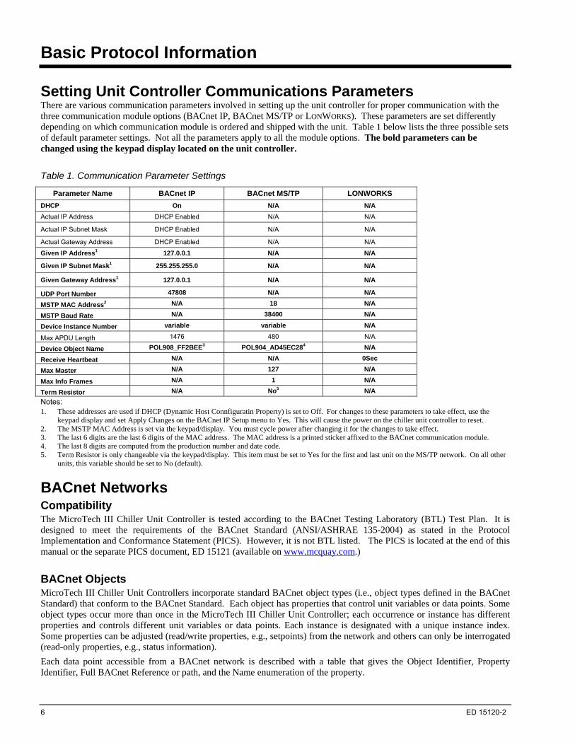
Setting Unit Controller Communications Parameters There are various communication parameters involved in setting up the unit controller for proper communication with the three communication module options (BACnet IP, BACnet MS/TP or LONWORKS). These parameters are set differently depending on which communication module is ordered and shipped with the unit. Table 1 below lists the three possible sets of default parameter settings. Not all the parameters apply to all the module options. The bold parameters can be changed using the keypad display located on the unit controller.
Table 1. Communication Parameter Settings
Parameter Name BACnet IP BACnet MS/TP LONWORKS
DHCP On N/A N/A
Actual IP Address DHCP Enabled N/A N/A
Actual IP Subnet Mask DHCP Enabled N/A N/A
Actual Gateway Address DHCP Enabled N/A N/A
Given IP Address1 127.0.0.1 N/A N/A
Given IP Subnet Mask1 255.255.255.0 N/A N/A
Given Gateway Address1 127.0.0.1 N/A N/A
UDP Port Number 47808 N/A N/A
MSTP MAC Address2 N/A 18 N/A
MSTP Baud Rate N/A 38400 N/A
Device Instance Number variable variable N/A
Max APDU Length 1476 480 N/A
Device Object Name POL908_FF2BEE3 POL904_AD45EC284 N/A
Receive Heartbeat N/A N/A 0Sec
Max Master N/A 127 N/A
Max Info Frames N/A 1 N/A
Term Resistor N/A No5 N/A
Notes: 1. These addresses are used if DHCP (Dynamic Host Connfiguratin Property) is set to Off. For changes to these parameters to take effect, use the
keypad display and set Apply Changes on the BACnet IP Setup menu to Yes. This will cause the power on the chiller unit controller to reset. 2. The MSTP MAC Address is set via the keypad/display. You must cycle power after changing it for the changes to take effect. 3. The last 6 digits are the last 6 digits of the MAC address. The MAC address is a printed sticker affixed to the BACnet communication module. 4. The last 8 digits are computed from the production number and date code. 5. Term Resistor is only changeable via the keypad/display. This item must be set to Yes for the first and last unit on the MS/TP network. On all other
units, this variable should be set to No (default).
BACnet Networks Compatibility The MicroTech III Chiller Unit Controller is tested according to the BACnet Testing Laboratory (BTL) Test Plan. It is designed to meet the requirements of the BACnet Standard (ANSI/ASHRAE 135-2004) as stated in the Protocol Implementation and Conformance Statement (PICS). However, it is not BTL listed. The PICS is located at the end of this manual or the separate PICS document, ED 15121 (available on www.mcquay.com.)
BACnet Objects MicroTech III Chiller Unit Controllers incorporate standard BACnet object types (i.e., object types defined in the BACnet Standard) that conform to the BACnet Standard. Each object has properties that control unit variables or data points. Some object types occur more than once in the MicroTech III Chiller Unit Controller; each occurrence or instance has different properties and controls different unit variables or data points. Each instance is designated with a unique instance index. Some properties can be adjusted (read/write properties, e.g., setpoints) from the network and others can only be interrogated (read-only properties, e.g., status information).
Each data point accessible from a BACnet network is described with a table that gives the Object Identifier, Property Identifier, Full BACnet Reference or path, and the Name enumeration of the property.

ED 15120-2 7
Example of BACnet Data Point Keypad Menu Path Main Menu_View/Set Unit_Status/Settings_Netwrk En SP=
Object Identifier Property Identifier
Object Type Type Enumeration Instance Property Name Property Enumeration
Binary Value 5 1 Present Value 85
Object Name
ChillerEnableOutput
Property Values
0 = Disable(Inactive)
1 = Enable(Active)
Object Identifier Object Identifiers are each designated with an Object type as defined in the BACnet specification. The first column of the data point definition gives the object type. This object happens to be Chiller Enable Output (See page 43.)
The object identifier is a property of the object that you can read from the object. The name of the property is “Object_Identifier” and the property identifier is 75.
Each object in the MicroTech III Chiller Unit Controller has a unique identifier. BACnet object identifiers are two-part numbers of BACnet Object Identifier data type. The first part identifies the object type (the first 10 bits of the 32-bit BACnet Object Identifier [See ANSI/ASHRAE 135-2004 BACnet A Data Communication Protocol for Building Automation and Control Networks]). The first column of the data point definition gives the object type. The second part identifies the instances of that particular object type (the last 22 bits of the 32-bit BACnet Object Identifier).
The object identifier is shown in the data points listing as two numbers. The first number is shown in the Type ID column and designates the Object type enumeration. The second number is shown in the Instance column and designates the instance of that particular object type.
The object identifier is a property of the object that you can read from the object code. The name of the property is “Object_Identifier” and the property identifier is 75. The ASHRAE BACnet specification reserves the first 128 numbers for ASHRAE defined objects. Manufacturers may define additional object types and assign a number above 127 as long as they conform to the requirements of the ASHRAE BACnet specification.
Each object also has a name. Object names are character strings. The object name is a property of the object that you can read from the object. The name of the property is “Object_Name” and the property identifier is 77.
Objects are sometimes referred to as an object type and instance number as they are in the BACnet specification. The example object above would be: Binary Value, Instance 1.
Property Identifier Each object has a number of properties or attributes. Each property has a unique identifier of BACnet Property Identifier data type. Property identifiers are an enumerated set; a number identifies each member. The Property Identifier enumeration number is shown in the Property ID column. In the example above the property identifier is 85.
Property Name Each property also has a unique name. Property names are character strings and shown in the Property Name column. In the example above the property name is Present Value.
Object Name The Object Name is the name of the object in the device. Object Names must be unique within each MicroTech III Chiller Unit Controller. In the example above the object name is ChillerEnableOutput.
Enumerated Values Some properties are standard data types and some are enumerated sets. If the property value is an enumerated set, all enumerated values and corresponding meaning are given in the Enumeration column of the data point listing.
MicroTech III Chiller Unit Controller Device Object Each BACnet compatible device (i.e. MicroTech III Chiller Unit Controller) can only have a single BACnet Device Object.
Device Object Identifier The MicroTech III Chiller Unit Controller Device Object Identifier uniquely specifies the unit within the network. The device object type for all devices is fixed by ASHRAE at 8. Therefore the device object instance number must be unique. The initial Device Object identifier is set at manufacturing. The device object identifier can be read from the unit controller. The name of the property is “Object_Identifier” and the property identifier is 75.
The initial device object instance number is calculated depending on the either the production code (IP) or the MAC Address (MS/TP). This number must be unique on the entire BACnet network. The object instance number can be changed via the keypad display. You must cycle power for the change to take effect.
! CAUTION
If another device in the network already has this object identifier (instance number), you must change the instance number of one device object, so that all devices in the network have a unique device identifier.
Device Object Name The Device Object Name uniquely specifies a device in the network. It must be unique in the network. The device name for the MicroTech III Chiller Unit Controller device is to be determined. The device name is the “prefix” of all object names in the MicroTech III Chiller Unit Controller. All objects include the device name and a period “.” preceding the object name.
The Device Object name is also available to the network in the device. The property name is “Object_Name” and property identifier is 77. For a BACnet IP card, the default Object Name is POL908_###### where ###### is the last 6 digits of the MAC address. For a BACnet MS/TP card, the default Object Name is POL904_######## where ######## is computed from the production number and date code.
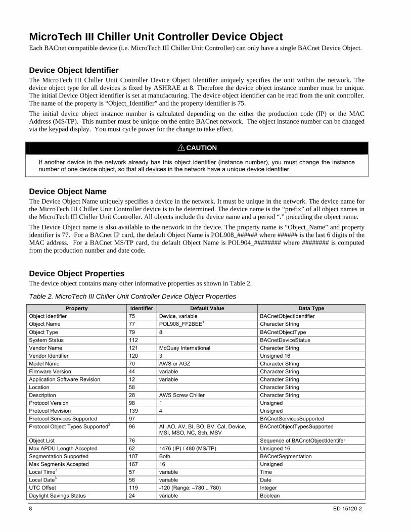
Device Object Properties The device object contains many other informative properties as shown in Table 2.
Table 2. MicroTech III Chiller Unit Controller Device Object Properties
Property Identifier Default Value Data Type
Object Identifier 75 Device, variable BACnetObjectIdentifier
Object Name 77 POL908_FF2BEE1 Character String
Object Type 79 8 BACnetObjectType
System Status 112 BACnetDeviceStatus
Vendor Name 121 McQuay International Character String
Vendor Identifier 120 3 Unsigned 16
Model Name 70 AWS or AGZ Character String
Firmware Version 44 variable Character String
Application Software Revision 12 variable Character String
Location 58 Character String
Description 28 AWS Screw Chiller Character String
Protocol Version 98 1 Unsigned
Protocol Revision 139 4 Unsigned
Protocol Services Supported 97 BACnetServicesSupported
Protocol Object Types Supported2 96 AI, AO, AV, BI, BO, BV, Cal, Device, MSI, MSO, NC, Sch, MSV
BACnetObjectTypesSupported
Object List 76 Sequence of BACnetObjectIdentifer
Max APDU Length Accepted 62 1476 (IP) / 480 (MS/TP) Unsigned 16
Segmentation Supported 107 Both BACnetSegmentation
Max Segments Accepted 167 16 Unsigned
Local Time3 57 variable Time
Local Date3 56 variable Date
UTC Offset 119 -120 (Range: –780 .. 780) Integer
Daylight Savings Status 24 variable Boolean
8 ED 15120-2
ED 15120-2 9
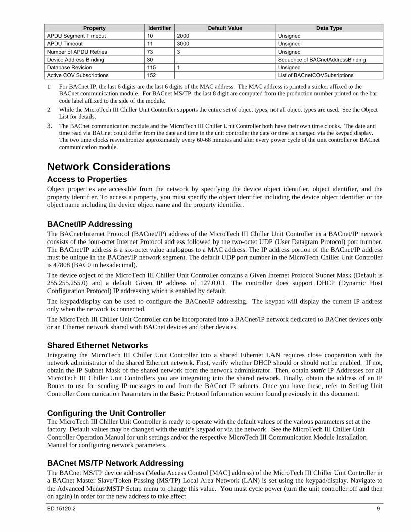
Property Identifier Default Value Data Type
APDU Segment Timeout 10 2000 Unsigned
APDU Timeout 11 3000 Unsigned
Number of APDU Retries 73 3 Unsigned
Device Address Binding 30 Sequence of BACnetAddressBinding
Database Revision 115 1 Unsigned
Active COV Subscriptions 152 List of BACnetCOVSubsriptions
1. For BACnet IP, the last 6 digits are the last 6 digits of the MAC address. The MAC address is printed a sticker affixed to the BACnet communication module. For BACnet MS/TP, the last 8 digit are computed from the production number printed on the bar code label affixed to the side of the module.
2. While the MicroTech III Chiller Unit Controller supports the entire set of object types, not all object types are used. See the Object List for details.
3. The BACnet communication module and the MicroTech III Chiller Unit Controller both have their own time clocks. The date and time read via BACnet could differ from the date and time in the unit controller the date or time is changed via the keypad display. The two time clocks resynchronize approximately every 60-68 minutes and after every power cycle of the unit controller or BACnet communication module.
Network Considerations Access to Properties Object properties are accessible from the network by specifying the device object identifier, object identifier, and the property identifier. To access a property, you must specify the object identifier including the device object identifier or the object name including the device object name and the property identifier.
BACnet/IP Addressing The BACnet/Internet Protocol (BACnet/IP) address of the MicroTech III Chiller Unit Controller in a BACnet/IP network consists of the four-octet Internet Protocol address followed by the two-octet UDP (User Datagram Protocol) port number. The BACnet/IP address is a six-octet value analogous to a MAC address. The IP address portion of the BACnet/IP address must be unique in the BACnet/IP network segment. The default UDP port number in the MicroTech Chiller Unit Controller is 47808 (BAC0 in hexadecimal).
The device object of the MicroTech III Chiller Unit Controller contains a Given Internet Protocol Subnet Mask (Default is 255.255.255.0) and a default Given IP address of 127.0.0.1. The controller does support DHCP (Dynamic Host Configuration Protocol) IP addressing which is enabled by default.
The keypad/display can be used to configure the BACnet/IP addressing. The keypad will display the current IP address only when the network is connected.
The MicroTech III Chiller Unit Controller can be incorporated into a BACnet/IP network dedicated to BACnet devices only or an Ethernet network shared with BACnet devices and other devices.
Shared Ethernet Networks Integrating the MicroTech III Chiller Unit Controller into a shared Ethernet LAN requires close cooperation with the network administrator of the shared Ethernet network. First, verify whether DHCP should or should not be enabled. If not, obtain the IP Subnet Mask of the shared network from the network administrator. Then, obtain static IP Addresses for all MicroTech III Chiller Unit Controllers you are integrating into the shared network. Finally, obtain the address of an IP Router to use for sending IP messages to and from the BACnet IP subnets. Once you have these, refer to Setting Unit Controller Communication Parameters in the Basic Protocol Information section found previously in this document.
Configuring the Unit Controller The MicroTech III Chiller Unit Controller is ready to operate with the default values of the various parameters set at the factory. Default values may be changed with the unit’s keypad or via the network. See the MicroTech III Chiller Unit Controller Operation Manual for unit settings and/or the respective MicroTech III Communication Module Installation Manual for configuring network parameters.
BACnet MS/TP Network Addressing The BACnet MS/TP device address (Media Access Control [MAC] address) of the MicroTech III Chiller Unit Controller in a BACnet Master Slave/Token Passing (MS/TP) Local Area Network (LAN) is set using the keypad/display. Navigate to the Advanced Menus\MSTP Setup menu to change this value. You must cycle power (turn the unit controller off and then on again) in order for the new address to take effect.
10 ED 15120-2
The BUS LED is green when the BACnet communication module is communicating with the network and is red when it is not communicating with the network. The default data transmission rate is set to 38,400 bps (baud). This rate can be changed to 9,600, 19,200 or 76,800 with the keypad/display. Refer to Setting Unit Controller Communications Parameters in the Basic Protocol Information section of this document.
LONWORKS Networks LONWORKS technology, developed by Echelon Corporation, is the basis for LonMark interoperable systems. This technology is independent of the communications media. The LonMark Interoperable Association has developed standards for interoperable LONWORKS technology systems. In particular they have published standards for HVAC equipment including the Chiller functional profile. This profile specifies a number of mandatory and optional standard network variables and standard configuration parameters. This manual defines these variables and parameters available in the MicroTech III Chiller Unit Controller.
Compatibility The MicroTech III Chiller Unit Controller with LONWORKS communication module operates in accordance with the Chiller functional profile of the LonMark Interoperability standard.
LonWorks Variables MicroTech III Chiller Unit Controllers incorporate LONWORKS network variables to access unit data points. The unit controller uses LONWORKS Standard Network Variable Types (SNVT) from each profile. Some data points can be adjusted (input network variables, nvi) (read/write attributes, e.g., setpoints) from the network and others can only be interrogated (output network variables, nvo) (read only attributes, e.g., status information). Configuration variables (nci) are included with the read/write attributes.
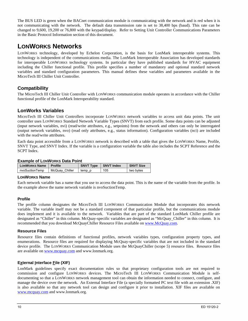
Each data point accessible from a LONWORKS network is described with a table that gives the LONWORKS Name, Profile, SNVT Type, and SNVT Index. If the variable is a configuration variable the table also includes the SCPT Reference and the SCPT Index. Example of LONWORKS Data Point
LONWORKS Name Profile SNVT Type SNVT Index SNVT Size
nvoSuctionTemp McQuay_Chiller temp_p 105 two bytes
LONWORKS Name Each network variable has a name that you use to access the data point. This is the name of the variable from the profile. In the example above the name network variable is nvoSuctionTemp.
Profile The profile column designates the MicroTech III LONWORKS Communication Module that incorporates this network variable. The variable itself may not be a standard component of that particular profile, but the communications module does implement and it is available to the network. Variables that are part of the standard LonMark Chiller profile are designated as “Chiller” in this column. McQuay-specific variables are designated as “McQuay_Chiller” in this column. It is recommended that you download McQuayChiller Resource Files available on www.McQuay.com.
Resource Files
Resource files contain definitions of functional profiles, network variables types, configuration property types, and enumerations. Resource files are required for displaying McQuay-specific variables that are not included in the standard device profile. The LONWORKS Communication Module uses the McQuayChiller (scope 5) resource files. Resource files are available on www.mcquay.com and www.lonmark.org.
External Interface File (XIF)
LonMark guidelines specify exact documentation rules so that proprietary configuration tools are not required to commission and configure LONWORKS devices. The MicroTech III LONWORKS Communication Module is self-documenting so that a LONWORKS network management tool can obtain the information needed to connect, configure, and manage the device over the network. An External Interface File (a specially formatted PC text file with an extension .XIF) is also available so that any network tool can design and configure it prior to installation. XIF files are available on www.mcquay.com and www.lonmark.org.
SNVT Type This column gives the name of the standard network variable type from the master list. SNVT Index This column gives the number of the standard network variable type from the master list. SCPT Reference This column gives the name of the Standard Configuration Parameter Type (SCPT) from the master list. SCPT Index This column gives the number of the Standard Configuration Parameter Type (SCPT) from the master list.
Network Considerations Network Topology Each MicroTech III LONWORKS Communication Module is equipped with an FTT-10A transceiver for network communications. This transceiver allows for (1) free topology network wiring schemes using twisted pair (unshielded) cable and (2) polarity insensitive connections at each node. These features greatly simplify installation and reduce network commissioning problems. Additional nodes may be added with little regard to existing cable routing.
Free Topology Networks
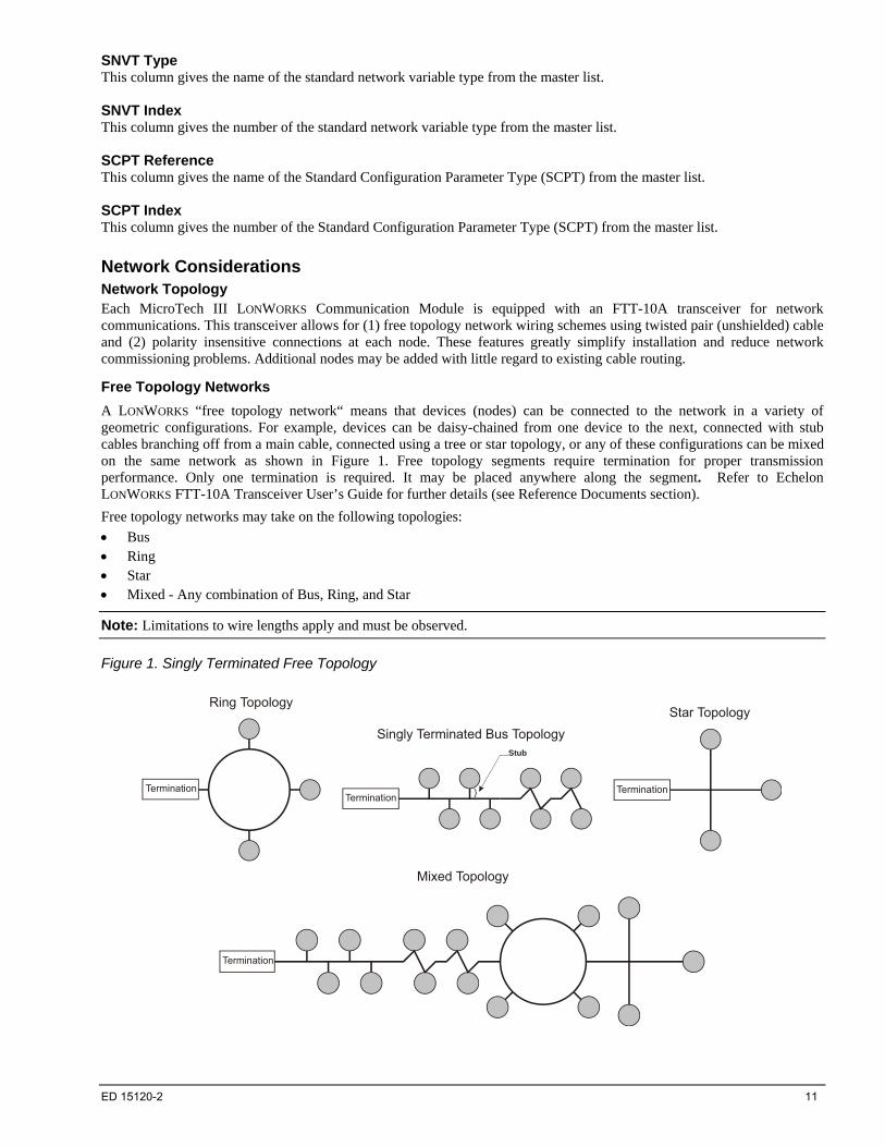
A LONWORKS “free topology network“ means that devices (nodes) can be connected to the network in a variety of geometric configurations. For example, devices can be daisy-chained from one device to the next, connected with stub cables branching off from a main cable, connected using a tree or star topology, or any of these configurations can be mixed on the same network as shown in Figure 1. Free topology segments require termination for proper transmission performance. Only one termination is required. It may be placed anywhere along the segment. Refer to Echelon LONWORKS FTT-10A Transceiver User’s Guide for further details (see Reference Documents section).
Free topology networks may take on the following topologies:
Bus Ring Star Mixed - Any combination of Bus, Ring, and Star
Note: Limitations to wire lengths apply and must be observed.
Figure 1. Singly Terminated Free Topology
Termination
Star Topology
Termination
Ring Topology
Termination
Singly Terminated Bus TopologyStub
}
Termination
Mixed Topology
ED 15120-2 11
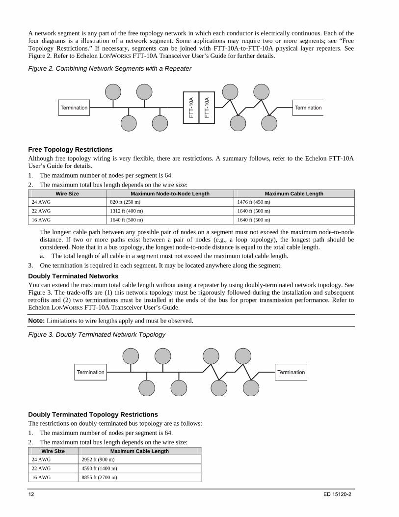
A network segment is any part of the free topology network in which each conductor is electrically continuous. Each of the four diagrams is a illustration of a network segment. Some applications may require two or more segments; see “Free Topology Restrictions.” If necessary, segments can be joined with FTT-10A-to-FTT-10A physical layer repeaters. See Figure 2. Refer to Echelon LONWORKS FTT-10A Transceiver User’s Guide for further details.
Figure 2. Combining Network Segments with a Repeater
Termination Termination
FT
T-1
0A
FT
T-1
0A
Free Topology Restrictions Although free topology wiring is very flexible, there are restrictions. A summary follows, refer to the Echelon FTT-10A User’s Guide for details.
1. The maximum number of nodes per segment is 64.
2. The maximum total bus length depends on the wire size: Wire Size Maximum Node-to-Node Length Maximum Cable Length
24 AWG 820 ft (250 m) 1476 ft (450 m)
22 AWG 1312 ft (400 m) 1640 ft (500 m)
16 AWG 1640 ft (500 m) 1640 ft (500 m)
The longest cable path between any possible pair of nodes on a segment must not exceed the maximum node-to-node distance. If two or more paths exist between a pair of nodes (e.g., a loop topology), the longest path should be considered. Note that in a bus topology, the longest node-to-node distance is equal to the total cable length. a. The total length of all cable in a segment must not exceed the maximum total cable length.
3. One termination is required in each segment. It may be located anywhere along the segment.
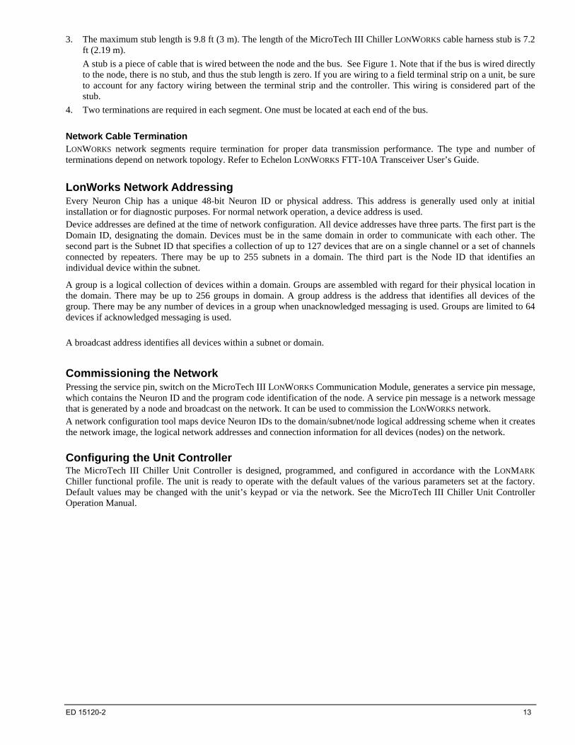
Doubly Terminated Networks You can extend the maximum total cable length without using a repeater by using doubly-terminated network topology. See Figure 3. The trade-offs are (1) this network topology must be rigorously followed during the installation and subsequent retrofits and (2) two terminations must be installed at the ends of the bus for proper transmission performance. Refer to Echelon LONWORKS FTT-10A Transceiver User’s Guide.
Note: Limitations to wire lengths apply and must be observed.
Figure 3. Doubly Terminated Network Topology
Termination Termination
Doubly Terminated Topology Restrictions The restrictions on doubly-terminated bus topology are as follows:
1. The maximum number of nodes per segment is 64.
2. The maximum total bus length depends on the wire size: Wire Size Maximum Cable Length
24 AWG 2952 ft (900 m)
22 AWG 4590 ft (1400 m)
16 AWG 8855 ft (2700 m)
12 ED 15120-2
ED 15120-2 13
3. The maximum stub length is 9.8 ft (3 m). The length of the MicroTech III Chiller LONWORKS cable harness stub is 7.2 ft (2.19 m).
A stub is a piece of cable that is wired between the node and the bus. See Figure 1. Note that if the bus is wired directly to the node, there is no stub, and thus the stub length is zero. If you are wiring to a field terminal strip on a unit, be sure to account for any factory wiring between the terminal strip and the controller. This wiring is considered part of the stub.
4. Two terminations are required in each segment. One must be located at each end of the bus.
Network Cable Termination LONWORKS network segments require termination for proper data transmission performance. The type and number of terminations depend on network topology. Refer to Echelon LONWORKS FTT-10A Transceiver User’s Guide.
LonWorks Network Addressing Every Neuron Chip has a unique 48-bit Neuron ID or physical address. This address is generally used only at initial installation or for diagnostic purposes. For normal network operation, a device address is used. Device addresses are defined at the time of network configuration. All device addresses have three parts. The first part is the Domain ID, designating the domain. Devices must be in the same domain in order to communicate with each other. The second part is the Subnet ID that specifies a collection of up to 127 devices that are on a single channel or a set of channels connected by repeaters. There may be up to 255 subnets in a domain. The third part is the Node ID that identifies an individual device within the subnet.
A group is a logical collection of devices within a domain. Groups are assembled with regard for their physical location in the domain. There may be up to 256 groups in domain. A group address is the address that identifies all devices of the group. There may be any number of devices in a group when unacknowledged messaging is used. Groups are limited to 64 devices if acknowledged messaging is used. A broadcast address identifies all devices within a subnet or domain.
Commissioning the Network Pressing the service pin, switch on the MicroTech III LONWORKS Communication Module, generates a service pin message, which contains the Neuron ID and the program code identification of the node. A service pin message is a network message that is generated by a node and broadcast on the network. It can be used to commission the LONWORKS network. A network configuration tool maps device Neuron IDs to the domain/subnet/node logical addressing scheme when it creates the network image, the logical network addresses and connection information for all devices (nodes) on the network.
Configuring the Unit Controller The MicroTech III Chiller Unit Controller is designed, programmed, and configured in accordance with the LONMARK Chiller functional profile. The unit is ready to operate with the default values of the various parameters set at the factory. Default values may be changed with the unit’s keypad or via the network. See the MicroTech III Chiller Unit Controller Operation Manual.
14 ED 15120-2
Typical Application: Minimum Integration
When you have integrated the unit into your network, you can monitor and control unit operation from your workstation. This section describes the basic information rquired to set up and display data for network integration.
Set up the Unit for Network Control To control the MicroTech III Chiller Unit Controller over the network, follow the setup steps below.
1. Set the Main Menu_View/Set Unit_Status/Settings_Control Source= to Local (default).
2. Using the keypad/display, setup the communication module for the network. See the appropriate IM for instructions.
3. Verify with the chiller/control company technician that the chiller is operational on BAS.
4. Set the Main Menu_View/Set Unit_Status/Settings_Control Source= to Network.
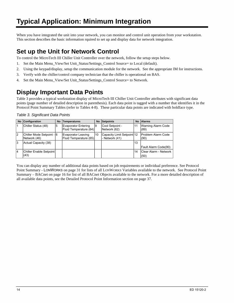
Display Important Data Points Table 3 provides a typical workstation display of MicroTech III Chiller Unit Controller attributes with significant data points (page number of detailed description in parenthesis). Each data point is tagged with a number that identifies it in the Protocol Point Summary Tables (refer to Tables 4-8). These particular data points are indicated with boldface type.
Table 3. Significant Data Points
No Configuration No Temperatures No Setpoints No Alarms
1 Chiller Status (48)
5 Evaporator Entering Fluid Temperature (64)
9 Cool Setpoint - Network (62)
11 Warning Alarm Code (89)
2 Chiller Mode Setpoint - Network (46)
6 Evaporator Leaving Fluid Temperature (65)
10 Capacity Limit Setpoint - Network (41)
12 Problem Alarm Code (90)
3 Actual Capacity (38) 13
Fault Alarm Code(90)
4 Chiller Enable Setpoint (43)
14 Clear Alarm - Network
(50)
You can display any number of additional data points based on job requirements or individual preference. See Protocol Point Summary - LONWORKS on page 31 for lists of all LONWORKS Variables available to the network. See Protocol Point Summary – BACnet on page 16 for list of all BACnet Objects available to the network. For a more detailed description of all available data points, see the Detailed Protocol Point Information section on page 37.

ED 15120-2 15
Alarms Alarms in a MicroTech III Chiller Unit Controller are divided into three classes: Faults, Problems, and Warnings.
Fault Alarms have the highest priority.
Problem Alarms have medium priority.
Warning Alarms have the lowest priority.
Notification Refer to the Alarms section (on page 80) for details on alarm monitoring and notification.
Clearing
BACnet
Alarms within MicroTech III Chiller Unit Controllers can be cleared via BACnet by setting the ClearAlarms variable to a value of 1. After the alarms are cleared, this variable will return to Normal (0).
LONWORKS
Using nviClearAlarm can clear alarms within MicroTech III Chiller Unit Controllers. To clear alarms, set the state property of nviClearAlarm to 1. The value property of nviClearAlarm is not used.
Unit Controller Sequence of Operation The sequence of operation for a MicroTech III Chiller Unit Controller depends on the control type. Refer to the MicroTech III Chiller Unit Controller Operation Manual for sequence of operation details, including keypad operation.
16 ED 15120-2
Protocol Point Summary – BACnet
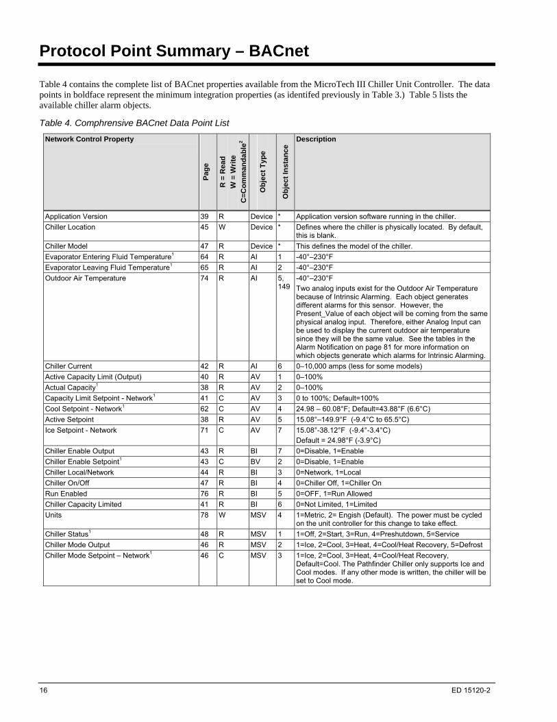
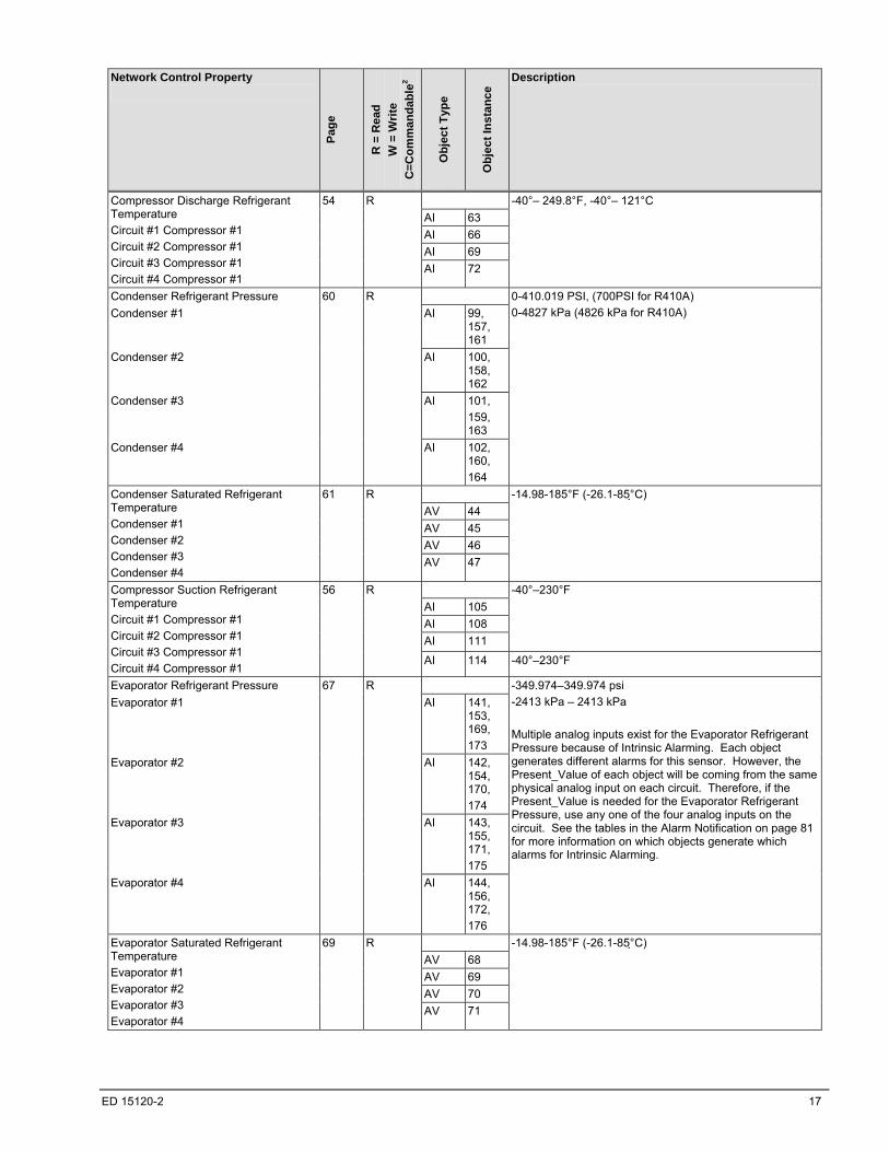
Table 4 contains the complete list of BACnet properties available from the MicroTech III Chiller Unit Controller. The data points in boldface represent the minimum integration properties (as identifed previously in Table 3.) Table 5 lists the available chiller alarm objects.
Table 4. Comphrensive BACnet Data Point List
Network Control Property
Pag
e
R =
Rea
d
W =
Wri
te
C=
Co
mm
an
da
ble
2
Ob
jec
t T
ype
Ob
jec
t In
sta
nce
Description
Application Version 39 R Device * Application version software running in the chiller.
Chiller Location 45 W Device * Defines where the chiller is physically located. By default, this is blank.
Chiller Model 47 R Device * This defines the model of the chiller.
Evaporator Entering Fluid Temperature1 64 R AI 1 -40°–230°F
Evaporator Leaving Fluid Temperature1 65 R AI 2 -40°–230°F
Outdoor Air Temperature 74 R AI 5, 149
-40°–230°F
Two analog inputs exist for the Outdoor Air Temperature because of Intrinsic Alarming. Each object generates different alarms for this sensor. However, the Present_Value of each object will be coming from the same physical analog input. Therefore, either Analog Input can be used to display the current outdoor air temperature since they will be the same value. See the tables in the Alarm Notification on page 81 for more information on which objects generate which alarms for Intrinsic Alarming.
Chiller Current 42 R AI 6 0–10,000 amps (less for some models)
Active Capacity Limit (Output) 40 R AV 1 0–100%
Actual Capacity1 38 R AV 2 0–100%
Capacity Limit Setpoint - Network1 41 C AV 3 0 to 100%; Default=100%
Cool Setpoint - Network1 62 C AV 4 24.98 – 60.08°F; Default=43.88°F (6.6°C)
Active Setpoint 38 R AV 5 15.08°–149.9°F (-9.4°C to 65.5°C)
Ice Setpoint - Network 71 C AV 7 15.08°-38.12°F (-9.4°-3.4°C)
Default = 24.98°F (-3.9°C)
Chiller Enable Output 43 R BI 7 0=Disable, 1=Enable
Chiller Enable Setpoint1 43 C BV 2 0=Disable, 1=Enable
Chiller Local/Network 44 R BI 3 0=Network, 1=Local
Chiller On/Off 47 R BI 4 0=Chiller Off, 1=Chiller On
Run Enabled 76 R BI 5 0=OFF, 1=Run Allowed
Chiller Capacity Limited 41 R BI 6 0=Not Limited, 1=Limited
Units 78 W MSV 4 1=Metric, 2= Engish (Default). The power must be cycled on the unit controller for this change to take effect.
Chiller Status1 48 R MSV 1 1=Off, 2=Start, 3=Run, 4=Preshutdown, 5=Service
Chiller Mode Output 46 R MSV 2 1=Ice, 2=Cool, 3=Heat, 4=Cool/Heat Recovery, 5=Defrost
Chiller Mode Setpoint – Network1 46 C MSV 3 1=Ice, 2=Cool, 3=Heat, 4=Cool/Heat Recovery, Default=Cool. The Pathfinder Chiller only supports Ice and Cool modes. If any other mode is written, the chiller will be set to Cool mode.
ED 15120-2 17
Network Control Property
Pag
e
R =
Rea
d
W =
Wri
te
C=
Co
mm
an
da
ble
2
Ob
jec
t T
ype
Ob
jec
t In
sta
nce
Description
AI 63
AI 66
AI 69
Compressor Discharge Refrigerant Temperature
Circuit #1 Compressor #1
Circuit #2 Compressor #1
Circuit #3 Compressor #1
Circuit #4 Compressor #1
54 R
AI 72
-40°– 249.8°F, -40°– 121°C
Condenser Refrigerant Pressure
Condenser #1 AI 99, 157, 161
Condenser #2 AI 100, 158, 162
Condenser #3 AI 101,
159, 163
Condenser #4
60 R
AI 102, 160,
164
0-410.019 PSI, (700PSI for R410A)
0-4827 kPa (4826 kPa for R410A)
AV 44
AV 45
AV 46
Condenser Saturated Refrigerant Temperature
Condenser #1
Condenser #2
Condenser #3
Condenser #4
61 R
AV 47
-14.98-185°F (-26.1-85° C)
AI 105
AI 108
AI 111
-40°–230°F Compressor Suction Refrigerant Temperature
Circuit #1 Compressor #1
Circuit #2 Compressor #1
Circuit #3 Compressor #1
Circuit #4 Compressor #1
56 R
AI 114 -40°–230°F
Evaporator Refrigerant Pressure
Evaporator #1 AI 141, 153, 169,
173
Evaporator #2 AI 142, 154, 170,
174
Evaporator #3 AI 143, 155, 171,
175
Evaporator #4
67 R
AI 144, 156, 172,
176
-349.974–349.974 psi
-2413 kPa – 2413 kPa
Multiple analog inputs exist for the Evaporator Refrigerant Pressure because of Intrinsic Alarming. Each object generates different alarms for this sensor. However, the Present_Value of each object will be coming from the same physical analog input on each circuit. Therefore, if the Present_Value is needed for the Evaporator Refrigerant Pressure, use any one of the four analog inputs on the circuit. See the tables in the Alarm Notification on page 81 for more information on which objects generate which alarms for Intrinsic Alarming.
AV 68
AV 69
AV 70
Evaporator Saturated Refrigerant Temperature
Evaporator #1
Evaporator #2
Evaporator #3
Evaporator #4
69 R
AV 71
-14.98-185°F (-26.1-85° C)

18 ED 15120-2
Network Control Property
Pag
e
R =
Rea
d
W =
Wri
te
C=
Co
mm
an
da
ble
2
Ob
jec
t T
ype
Ob
jec
t In
sta
nce
Description
AV 74
AV 75
AV 76
AV 77
AV 78
AV 79
AV 80
Compressor Run Hours
Circuit #1 Compressor #1
Circuit #1 Compressor #2
Circuit #1 Compressor #3
Circuit #2 Compressor #1
Circuit #2 Compressor #2
Circuit #2 Compressor #3
Circuit #3 Compressor #1
Circuit #4 Compressor #1
56 W
AV 83
0 –999,999
AV 92
AV 93
AV 94
AV 95
AV 96
AV 97
AV 98
Compressor Starts
Circuit #1 Compressor #1
Circuit #1 Compressor #2
Circuit #1 Compressor #3
Circuit #2 Compressor #1
Circuit #2 Compressor #2
Circuit #2 Compressor #3
Circuit #3 Compressor #1
Circuit #4 Compressor #1
57 W
AV 101
0 –65,535
Evaporator Flow Switch Status 64 R BI 2 0=No Flow, 1=Flow
BI 8
Evaporator Pump Status
Pump #1
Pump #2
66 R
BI 9
0=Pump Off Request, 1=Pump On Request
AV 112
Evaporator Pump Run Hours
Pump #1
Pump #2
66 W
AV 113
0 –999,999
AI 165
AI 166
AI 167
Oil Feed Pressure
Circuit #1 Compressor #1
Circuit #2 Compressor #1
Circuit #3 Compressor #1
Circuit #4 Compressor #1
73 R
AI 168
These objects are used for Intrinsic Alarming.
AV 8
AV 11
Compressor Percent RLA
Circuit #1 Compressor #1
Circuit #2 Compressor #1
Circuit #3 Compressor #1
54 R
AV 14
Compressor Current
Circuit #1 Compressor #1
AI 9,
181,
184
Circuit #2 Compressor #1
AI 12,
182,
185
Circuit #3 Compressor #1
52 R
AI 15,
183,
186
Indicates the average current of the compressor motor. These objects are used for Intrinsic Alarming.
Multiple analog inputs exist for Compressor Current because of Intrinsic Alarming. Each object generates different alarms for this sensor. However, the Present_Value of each object will be coming from the same physical analog input on each circuit. Therefore, if the Present_Value is needed for Compressor Current, use any one of the four analog inputs on the circuit. See the tables in the Alarm Notification on page 81 for more information on which objects generate which alarms for Intrinsic Alarming.
AI 27
AI 30
Compressor Voltage
Circuit #1 Compressor #1
Circuit #2 Compressor #1
Circuit #3 Compressor #1
59 R
AI 33
AI 45
Compressor Power
Circuit #1 Compressor #1
Circuit #2 Compressor #1
55 R
AI 48

ED 15120-2 19
Network Control Property
Pag
e
R =
Rea
d
W =
Wri
te
C=
Co
mm
an
da
ble
2
Ob
jec
t T
ype
Ob
jec
t In
sta
nce
Description
Circuit #3 Compressor #1 AI 51
AI 178
AI 179
VFD Temp
Circuit #1 Compressor #1
Circuit #2 Compressor #1
Circuit #3 Compressor #1
78 R
AI 180
Temperature of the compressor VFD heatsink. These objects are used for Intrinsic Alarming.
1Denotes data points for typical minimum integration. 2This column defines whether the Present_Value property of the object is Read Only (R), Read/Write (W), or Commandable (C).
Commandable variables are read/write, but they contain a priority array (1-16). Any priority can be written if the MicroTech III Chiller Unit Controller is communicating via BACnet MS/TP or BACnet IP. However, LonWorks and Modbus protocols always write at Priority 8.
Table 5. Chiller Alarm Objects
Network Control Property
Pag
e
R =
Rea
d
W =
Wri
te
C=
Co
mm
an
da
ble
1
Ob
jec
t T
ype
Ob
jec
t In
sta
nce
Description
Alarm Digital Output 39 R BI 10 0=No Alarm, 1=Alarm
Clear Alarm - Network3 50 C BV 8 0=Normal, 1=Clear Alarm
Warning Alarm Code3 89 R AV 903 0=No Alarms
513=Evaporator Entering Water Temperature Sensor Warning
2049=Bad setpoint override input
2305=Bad demand limit input
2817=Unit power restore
3105=Circuit 1 failed pumpdown
3137=Circuit 2 Failed pumpdown
3169=Circuit 3 failed pumpdown
3201=Circuit 4 failed pumpdown
3329=External Event
3585=Bad Current Limit Input
3841=Option Controller Communication Failed
Problems Alarm Code3 90 R AV 904 0=No Alarms,
16418=RESTART DELAYED - Power Loss While Running Circuit #1
16450=RESTART DELAYED - Power Loss While Running Circuit #2
16482=RESTART DELAYED - Power Loss While Running Circuit #3
16514=RESTART DELAYED - Power Loss While Running Circuit #4
16642=START INHIBITED - Ambient Temperature Low 16898=INHIBIT LOAD–Condenser Pressure High
17186=INHIBIT LOAD–Condenser Pressure High Circuit #1
17218=INHIBIT LOAD–Condenser Pressure High Circuit #2 17250=INHIBIT LOAD–Condenser Pressure High Circuit #3 17282=INHIBIT LOAD–Condenser Pressure High Circuit #4 17698=UNLOAD - Condenser Pressure High Circuit #1 17730=UNLOAD – Condenser Pressure High Circuit #2 17762=UNLOAD – Condenser Pressure High Circuit #3 17794=UNLOAD – Condenser Pressure High Circuit #4 19490=INHIBIT LOAD - Evaporator Pressure Low Circuit #1 19522=INHIBIT LOAD - Evaporator Pressure Low Circuit #2 19554=INHIBIT LOAD - Evaporator Pressure Low Circuit #3 19586=INHIBIT LOAD - Evaporator Pressure Low Circuit #4 20002=UNLOAD - Evaporator Pressure Low Circuit #1 20034=UNLOAD - Evaporator Pressure Low Circuit #2 20066=UNLOAD - Evaporator Pressure Low Circuit #3 20098=UNLOAD - Evaporator Pressure Low Circuit #4
20262=UNLOAD-Comp Motor Current High Circuit #1, Comp #1
20294=UNLOAD-Comp Motor Current High Circuit #2, Comp #1
20 ED 15120-2
Network Control Property
Pag
e
R =
Rea
d
W =
Wri
te
C=
Co
mm
an
da
ble
1
Ob
jec
t T
ype
Ob
jec
t In
sta
nce
Description
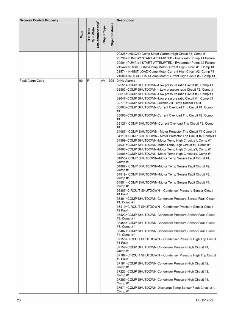
20326=UNLOAD-Comp Motor Current High Circuit #3, Comp #1
20738=PUMP #2 START ATTEMPTED - Evaporator Pump #1 Failure
20994=PUMP #1 START ATTEMPTED - Evaporator Pump #2 Failure
21542=INHIBIT LOAD-Comp Motor Current High Circuit #1, Comp #1
21574=INHIBIT LOAD-Comp Motor Current High Circuit #2, Comp #1
21606= INHIBIT LOAD-Comp Motor Current High Circuit #3, Comp #1
Fault Alarm Code3 90 R AV 905 0=No Alarms
32551=COMP SHUTDOWN–Low pressure ratio Circuit #1, Comp #1
32583=COMP SHUTDOWN – Low pressure ratio Circuit #2, Comp #1
32615=COMP SHUTDOWN–Low pressure ratio Circuit #3, Comp #1
32647=COMP SHUTDOWN–Low pressure ratio Circuit #4, Comp #1
32771=COMP SHUTDOWN-Outside Air Temp Sensor Fault,
33063=COMP SHUTDOWN-Current Overload Trip Circuit #1, Comp #1
33095=COMP SHUTDOWN-Current Overload Trip Circuit #2, Comp #1
33127= COMP SHUTDOWN-Current Overload Trip Circuit #3, Comp #1
34087= COMP SHUTDOWN– Motor Protector Trip Circuit #1 Comp #1
34119= COMP SHUTDOWN– Motor Protector Trip Circuit #2 Comp #1
34599=COMP SHUTDOWN–Motor Temp High Circuit #1, Comp #1
34631=COMP SHUTDOWN-Motor Temp High Circuit #2, Comp #1
34663=COMP SHUTDOWN–Motor Temp High Circuit #3, Comp #1
34695=COMP SHUTDOWN–Motor Temp High Circuit #4, Comp #1
34855= COMP SHUTDOWN–Motor Temp Sensor Fault Circuit #1, Comp #1
34887= COMP SHUTDOWN–Motor Temp Sensor Fault Circuit #2, Comp #1
34919= COMP SHUTDOWN–Motor Temp Sensor Fault Circuit #3, Comp #1
34951= COMP SHUTDOWN–Motor Temp Sensor Fault Circuit #4, Comp #1
36387=CIRCUIT SHUTDOWN – Condensor Pressure Sensor Circuit #1 Fault
36391=COMP SHUTDOWN-Condenser Pressure Sensor Fault Circuit #1, Comp #1
36419=CIRCUIT SHUTDOWN – Condensor Pressure Sensor Circuit #2 Fault
36423=COMP SHUTDOWN-Condenser Pressure Sensor Fault Circuit #2, Comp #1
36455=COMP SHUTDOWN-Condenser Pressure Sensor Fault Circuit #3, Comp #1
36487=COMP SHUTDOWN-Condenser Pressure Sensor Fault Circuit #4, Comp #1
37155=CIRCUIT SHUTDOWN – Condenser Pressure High Trip Circuit #1 Fault
37159=COMP SHUTDOWN-Condenser Pressure High Circuit #1, Comp #1
37187=CIRCUIT SHUTDOWN – Condenser Pressure High Trip Circuit #2 Fault
37191=COMP SHUTDOWN-Condenser Pressure High Circuit #2, Comp #1
37223=COMP SHUTDOWN-Condenser Pressure High Circuit #3, Comp #1
37255=COMP SHUTDOWN-Condenser Pressure High Circuit #4, Comp #1
37671=COMP SHUTDOWN-Discharge Temp Sensor Fault Circuit #1, Comp #1

ED 15120-2 21
Network Control Property
Pag
e
R =
Rea
d
W =
Wri
te
C=
Co
mm
an
da
ble
1
Ob
jec
t T
ype
Ob
jec
t In
sta
nce
Description
37703=COMP SHUTDOWN-Discharge Temp Sensor Fault Circuit #2, Comp #1
37735=COMP SHUTDOWN-Discharge Temp Sensor Fault Circuit #3, Comp #1
37767=COMP SHUTDOWN-Discharge Temp Sensor Fault Circuit #4, Comp #1
37927=COMP SHUTDOWN-Discharge Temp High Circuit #1, Comp #1
37959=COMP SHUTDOWN-Discharge Temp High Circuit #2, Comp #1
37991=COMP SHUTDOWN-Discharge Temp High Circuit #3, Comp #1
38023=COMP SHUTDOWN-Discharge Temp High Circuit #4, Comp #1
38403=UNIT SHUTDOWN-Evaporator Water Flow Loss,
38659=UNIT SHUTDOWN–Evaporator Leaving Water Temp Low (Freeze)
38915=COMP SHUTDOWN-Evaporator Pressure Low
39203=CIRCUIT SHUTDOWN – Low Evaporator Pressure Trip Circuit #1 Fault
39207=COMP SHUTDOWN-Evaporator Pressure Low Circuit #1, Comp #1
39235=CIRCUIT SHUTDOWN – Low Evaporator Pressure Trip Circuit #2 Fault
39239=COMP SHUTDOWN–Evaporator Pressure Low Circuit #2, Comp #1
39271=COMP SHUTDOWN-Evaporator Pressure Low Circuit #3, Comp #1
39303=COMP SHUTDOWN–Evaporator Pressure Low Circuit #4, Comp #1
39715=CIRCUIT SHUTDOWN – Evaporator Pressure Sensor Circuit #1 Fault
39719=COMP SHUTDOWN-Evaporator Pressure Sensor Fault Circuit #1, Comp #1
39747=CIRCUIT SHUTDOWN – Evaporator Pressure Sensor Circuit #2 Fault
39751=COMP SHUTDOWN-Evaporator Pressure Sensor Fault Circuit #2, Comp #1
39783=COMP SHUTDOWN-Evaporator Pressure Sensor Fault Circuit #3, Comp #1
39815=COMP SHUTDOWN-Evaporator Pressure Sensor Fault Circuit #4, Comp #1
41255=COMP LOCKOUT-Number of Allowed Re-Starts Exceeded Circuit #1, Comp #1
41287=COMP LOCKOUT-Number of Allowed Re-Starts Exceeded Circuit #2, Comp #1
41319=COMP LOCKOUT-Number of Allowed Re-Starts Exceeded Circuit #3, Comp #1
41351=COMP LOCKOUT-Number of Allowed Re-Starts Exceeded Circuit #4, Comp #1
41475=UNIT SHUTDOWN-Evaporator Leaving Water Temp Sensor Fault
41731=UNIT SHUTDOWN-Evaporator Entering Water Temp Sensor Failure
42535=COMP SHUTDOWN-Mechanical High Pressure Trip Circuit #1, Comp #1
42567=COMP SHUTDOWN-Mechanical High Pressure Trip Circuit #2, Comp #1
42599=COMP SHUTDOWN-Mechanical High Pressure Trip Circuit #3, Comp #1
42631=COMP SHUTDOWN-Mechanical High Pressure Trip Circuit #4,
22 ED 15120-2
Network Control Property
Pag
e
R =
Rea
d
W =
Wri
te
C=
Co
mm
an
da
ble
1
Ob
jec
t T
ype
Ob
jec
t In
sta
nce
Description
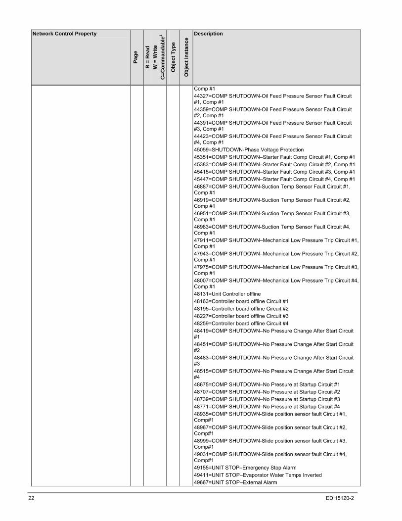
Comp #1
44327=COMP SHUTDOWN-Oil Feed Pressure Sensor Fault Circuit #1, Comp #1
44359=COMP SHUTDOWN-Oil Feed Pressure Sensor Fault Circuit #2, Comp #1
44391=COMP SHUTDOWN-Oil Feed Pressure Sensor Fault Circuit #3, Comp #1
44423=COMP SHUTDOWN-Oil Feed Pressure Sensor Fault Circuit #4, Comp #1
45059=SHUTDOWN-Phase Voltage Protection
45351=COMP SHUTDOWN–Starter Fault Comp Circuit #1, Comp #1
45383=COMP SHUTDOWN–Starter Fault Comp Circuit #2, Comp #1
45415=COMP SHUTDOWN–Starter Fault Comp Circuit #3, Comp #1
45447=COMP SHUTDOWN–Starter Fault Comp Circuit #4, Comp #1
46887=COMP SHUTDOWN-Suction Temp Sensor Fault Circuit #1, Comp #1
46919=COMP SHUTDOWN-Suction Temp Sensor Fault Circuit #2, Comp #1
46951=COMP SHUTDOWN-Suction Temp Sensor Fault Circuit #3, Comp #1
46983=COMP SHUTDOWN-Suction Temp Sensor Fault Circuit #4, Comp #1
47911=COMP SHUTDOWN–Mechanical Low Pressure Trip Circuit #1, Comp #1
47943=COMP SHUTDOWN–Mechanical Low Pressure Trip Circuit #2, Comp #1
47975=COMP SHUTDOWN–Mechanical Low Pressure Trip Circuit #3, Comp #1
48007=COMP SHUTDOWN–Mechanical Low Pressure Trip Circuit #4, Comp #1
48131=Unit Controller offline
48163=Controller board offline Circuit #1
48195=Controller board offline Circuit #2
48227=Controller board offline Circuit #3
48259=Controller board offline Circuit #4
48419=COMP SHUTDOWN–No Pressure Change After Start Circuit #1
48451=COMP SHUTDOWN–No Pressure Change After Start Circuit #2
48483=COMP SHUTDOWN–No Pressure Change After Start Circuit #3
48515=COMP SHUTDOWN–No Pressure Change After Start Circuit #4
48675=COMP SHUTDOWN–No Pressure at Startup Circuit #1
48707=COMP SHUTDOWN–No Pressure at Startup Circuit #2
48739=COMP SHUTDOWN–No Pressure at Startup Circuit #3
48771=COMP SHUTDOWN–No Pressure at Startup Circuit #4
48935=COMP SHUTDOWN-Slide position sensor fault Circuit #1, Comp#1
48967=COMP SHUTDOWN-Slide position sensor fault Circuit #2, Comp#1
48999=COMP SHUTDOWN-Slide position sensor fault Circuit #3, Comp#1
49031=COMP SHUTDOWN-Slide position sensor fault Circuit #4, Comp#1
49155=UNIT STOP–Emergency Stop Alarm
49411=UNIT STOP–Evaporator Water Temps Inverted
49667=UNIT STOP–External Alarm
ED 15120-2 23
Network Control Property
Pag
e
R =
Rea
d
W =
Wri
te
C=
Co
mm
an
da
ble
1
Ob
jec
t T
ype
Ob
jec
t In
sta
nce
Description
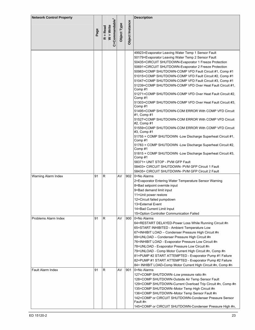
49923=Evaporator Leaving Water Temp 1 Sensor Fault
50179=Evaporator Leaving Water Temp 2 Sensor Fault
50435=CIRCUIT SHUTDOWN-Evaporator 1 Freeze Protection
50691=CIRCUIT SHUTDOWN-Evaporator 2 Freeze Protection
50983=COMP SHUTDOWN-COMP VFD Fault Circuit #1, Comp #1
51015=COMP SHUTDOWN-COMP VFD Fault Circuit #2, Comp #1
51047=COMP SHUTDOWN-COMP VFD Fault Circuit #3, Comp #1
51239=COMP SHUTDOWN-COMP VFD Over Heat Fault Circuit #1, Comp #1
51271=COMP SHUTDOWN-COMP VFD Over Heat Fault Circuit #2, Comp #1
51303=COMP SHUTDOWN-COMP VFD Over Heat Fault Circuit #3, Comp #1
51495=COMP SHUTDOWN-COM ERROR With COMP VFD Circuit #1, Comp #1
51527=COMP SHUTDOWN-COM ERROR With COMP VFD Circuit #2, Comp #1
51559=COMP SHUTDOWN-COM ERROR With COMP VFD Circuit #3, Comp #1
51755 = COMP SHUTDOWN -Low Discharge Superheat Circuit #1, Comp #1
51783 = COMP SHUTDOWN -Low Discharge Superheat Circuit #2, Comp #1
51815 = COMP SHUTDOWN -Low Discharge Superheat Circuit #3, Comp #1
58371= UNIT STOP - PVM GFP Fault
58403= CIRCUIT SHUTDOWN- PVM GFP Circuit 1 Fault
58435= CIRCUIT SHUTDOWN- PVM GFP Circuit 2 Fault
Warning Alarm Index 91 R AV 902 0=No Alarms
2=Evaporator Entering Water Temperature Sensor Warning
8=Bad setpoint override input
9=Bad demand limit input
11=Unit power restore
12=Circuit failed pumpdown
13=External Event
14=Bad Current Limit Input
15=Option Controller Communication Failed
Problems Alarm Index 91 R AV 900 0=No Alarms
64=RESTART DELAYED-Power Loss While Running Circuit #n
65=START INHIBITED - Ambient Temperature Low
67=INHIBIT LOAD – Condenser Pressure High Circuit #n
69=UNLOAD – Condenser Pressure High Circuit #n
76=INHIBIT LOAD - Evaporator Pressure Low Circuit #n
78=UNLOAD - Evaporator Pressure Low Circuit #n
79=UNLOAD - Comp Motor Current High Circuit #n, Comp #n
81=PUMP #2 START ATTEMPTED - Evaporator Pump #1 Failure
82=PUMP #1 START ATTEMPTED - Evaporator Pump #2 Failure
84= INHIBIT LOAD-Comp Motor Current High Circuit #n, Comp #n
Fault Alarm Index 91 R AV 901 0=No Alarms
127=COMP SHUTDOWN–Low pressure ratio #n
128=COMP SHUTDOWN-Outside Air Temp Sensor Fault
129=COMP SHUTDOWN-Current Overload Trip Circuit #n, Comp #n
135=COMP SHUTDOWN–Motor Temp High Circuit #n
136=COMP SHUTDOWN–Motor Temp Sensor Fault #n
142=COMP or CIRCUIT SHUTDOWN-Condenser Pressure Sensor Fault #n
145=COMP or CIRCUIT SHUTDOWN-Condenser Pressure High #n,
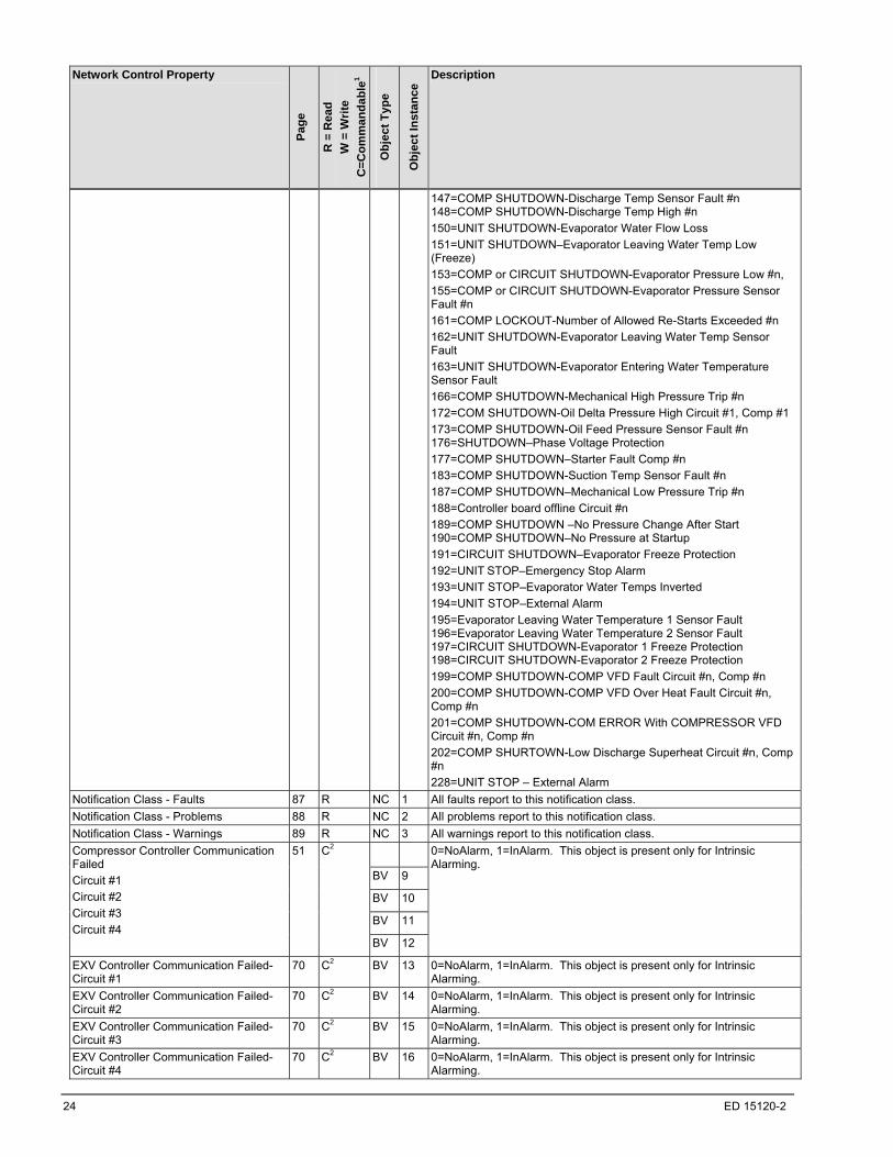
24 ED 15120-2
Network Control Property
Pag
e
R =
Rea
d
W =
Wri
te
C=
Co
mm
an
da
ble
1
Ob
jec
t T
ype
Ob
jec
t In
sta
nce
Description
147=COMP SHUTDOWN-Discharge Temp Sensor Fault #n 148=COMP SHUTDOWN-Discharge Temp High #n
150=UNIT SHUTDOWN-Evaporator Water Flow Loss
151=UNIT SHUTDOWN–Evaporator Leaving Water Temp Low (Freeze)
153=COMP or CIRCUIT SHUTDOWN-Evaporator Pressure Low #n,
155=COMP or CIRCUIT SHUTDOWN-Evaporator Pressure Sensor Fault #n
161=COMP LOCKOUT-Number of Allowed Re-Starts Exceeded #n
162=UNIT SHUTDOWN-Evaporator Leaving Water Temp Sensor Fault
163=UNIT SHUTDOWN-Evaporator Entering Water Temperature Sensor Fault
166=COMP SHUTDOWN-Mechanical High Pressure Trip #n
172=COM SHUTDOWN-Oil Delta Pressure High Circuit #1, Comp #1
173=COMP SHUTDOWN-Oil Feed Pressure Sensor Fault #n 176=SHUTDOWN–Phase Voltage Protection
177=COMP SHUTDOWN–Starter Fault Comp #n
183=COMP SHUTDOWN-Suction Temp Sensor Fault #n
187=COMP SHUTDOWN–Mechanical Low Pressure Trip #n
188=Controller board offline Circuit #n
189=COMP SHUTDOWN –No Pressure Change After Start 190=COMP SHUTDOWN–No Pressure at Startup
191=CIRCUIT SHUTDOWN–Evaporator Freeze Protection
192=UNIT STOP–Emergency Stop Alarm
193=UNIT STOP–Evaporator Water Temps Inverted
194=UNIT STOP–External Alarm
195=Evaporator Leaving Water Temperature 1 Sensor Fault 196=Evaporator Leaving Water Temperature 2 Sensor Fault 197=CIRCUIT SHUTDOWN-Evaporator 1 Freeze Protection 198=CIRCUIT SHUTDOWN-Evaporator 2 Freeze Protection
199=COMP SHUTDOWN-COMP VFD Fault Circuit #n, Comp #n
200=COMP SHUTDOWN-COMP VFD Over Heat Fault Circuit #n, Comp #n
201=COMP SHUTDOWN-COM ERROR With COMPRESSOR VFD Circuit #n, Comp #n
202=COMP SHURTOWN-Low Discharge Superheat Circuit #n, Comp #n
228=UNIT STOP – External Alarm
Notification Class - Faults 87 R NC 1 All faults report to this notification class.
Notification Class - Problems 88 R NC 2 All problems report to this notification class.
Notification Class - Warnings 89 R NC 3 All warnings report to this notification class.
BV 9
BV 10
BV 11
Compressor Controller Communication Failed
Circuit #1
Circuit #2
Circuit #3
Circuit #4
51 C2
BV 12
0=NoAlarm, 1=InAlarm. This object is present only for Intrinsic Alarming.
EXV Controller Communication Failed-Circuit #1
70 C2 BV 13 0=NoAlarm, 1=InAlarm. This object is present only for Intrinsic Alarming.
EXV Controller Communication Failed-Circuit #2
70 C2 BV 14 0=NoAlarm, 1=InAlarm. This object is present only for Intrinsic Alarming.
EXV Controller Communication Failed-Circuit #3
70 C2 BV 15 0=NoAlarm, 1=InAlarm. This object is present only for Intrinsic Alarming.
EXV Controller Communication Failed-Circuit #4
70 C2 BV 16 0=NoAlarm, 1=InAlarm. This object is present only for Intrinsic Alarming.

ED 15120-2 25
Network Control Property
Pag
e
R =
Rea
d
W =
Wri
te
C=
Co
mm
an
da
ble
1
Ob
jec
t T
ype
Ob
jec
t In
sta
nce
Description
Alarm/Limit Controller Communication Failed
92 C2 BV 17 0=NoAlarm, 1=InAlarm. This object is present only for Intrinsic Alarming.
Fan Controller Communication Failed-Circuit #1 & Circuit #2
71 C2 BV 18 0=NoAlarm, 1=InAlarm. This object is present only for Intrinsic Alarming.
Fan Controller Communication Failed-Circuit #3
71 C2 BV 19 0=NoAlarm, 1=InAlarm. This object is present only for Intrinsic Alarming.
Fan Controller Communication Failed-Circuit #4
71 C2 BV 20 0=NoAlarm, 1=InAlarm. This object is present only for Intrinsic Alarming.
Fan Controller Communication Failed-Circuit #3 & Circuit #4
71 C2 BV 21 0=NoAlarm, 1=InAlarm. This object is present only for Intrinsic Alarming.
Evap LWT 1 65 R AI 151 0=NoAlarm, 1=InAlarm. This object is present only for Intrinsic Alarming.
Evap LWT 2 65 R AI 152 0=NoAlarm, 1=InAlarm. This object is present only for Intrinsic Alarming.
Evaporator Entering Water Temperature Sensor Fault
124 C2 BV 917 0=No Alarm, 1=In Alarm.
Network Control Property
Pag
e
R =
Rea
d
W =
Wri
te
C=
Co
mm
an
da
ble
1
Ob
jec
t T
ype
Ob
jec
t In
sta
nce
Description
Evaporator Entering Water Temperature Sensor Warning
95 C2 BV 501 0=No Alarm, 1=In Alarm.
Bad Setpoint Override Input Warning 93 C2 BV 512 0=No Alarm, 1=In Alarm. This object is used for Intrinsic Alarming.
Bad Demand Limit Input Warning 93 C2 BV 513 0=No Alarm, 1=In Alarm. This object is used for Intrinsic Alarming.
UNIT Power Restore Warning4
131 C2 BV 515 0=No Alarm, 1=In Alarm. This object is used for Intrinsic Alarming.
BV 516
BV 517
BV 518
Circuit #n Failed Pumpdown Warning
Circuit #1
Circuit #2
Circuit #3
Circuit #4
94 C2
BV 519
0=No Alarm, 1=In Alarm. These objects are used for Intrinsic Alarming.
BV 529
BV 530
BV 531
Power Loss While Running Circuit #n Problem
Circuit #1
Circuit #2
Circuit #3
Circuit #4
129 C2
BV 532
0=No Alarm, 1=In Alarm. These objects are used for Intrinsic Alarming.
Ambient Temperature Low Problem 92 C2 BV 533 0=No Alarm, 1=In Alarm
BV 535
BV 536
BV 537
INHIBIT LOAD – Condenser Pressure High Circuit #n Problem4
Circuit #1
Circuit #2
Circuit #3
Circuit #4
127 C2
BV 538
0=No Alarm, 1=In Alarm
BV 540
BV 541
BV 542
UNLOAD – Condenser Pressure High #n Prob4
Circuit #1
Circuit #2
Circuit #3
Circuit #4
135 C2
BV 543
0=No Alarm, 1=In Alarm

26 ED 15120-2
Network Control Property
Pag
e
R =
Rea
d
W =
Wri
te
C=
Co
mm
an
da
ble
1
Ob
jec
t T
ype
Ob
jec
t In
sta
nce
Description
BV 556
BV 557
BV 558
INHIBIT LOAD - Evap Pressure Low #n Prob4
Circuit #1
Circuit #2
Circuit #3
Circuit #4
128 C2
BV 559
0=No Alarm, 1=In Alarm
BV 561
BV 562
BV 563
UNLOAD - Evap Pressure Low #n Problem4
Circuit #1
Circuit #2
Circuit #3
Circuit #4
136 C2
BV 564
0=No Alarm, 1=In Alarm
BV 565
BV 567
UNLOAD - Compressor Motor Current High #n Problem4
Circuit #1 Compressor #1
Circuit #2 Compressor #1
Circuit #3 Compressor #1
134 C2
BV 569
0=No Alarm, 1=In Alarm
PUMP #2 START ATTEMPTED - Evaporator Pump #1 Failure
125 C2 BV 575 0=No Alarm, 1=In Alarm
PUMP #1 START ATTEMPTED - Evaporator Pump #2 Failure
126 C2 BV 576 0=No Alarm, 1=In Alarm
BV 578
BV 580
INHIBIT LOAD - Compressor Motor Current High #n Problem4
Circuit #1 Compressor #1
Circuit #2 Compressor #1
Circuit #3 Compressor #1
126 C2
BV 582
0=No Alarm, 1=In Alarm
BV 599
BV 601
BV 603
COMPRESSOR SHUTDOWN – Low Pressure Ratio #n Fault
Circuit #1 Compressor #1
Circuit #2 Compressor #1
Circuit #3 Compressor #1
Circuit #4 Compressor #1
107 C2
BV 604
0=No Alarm, 1=In Alarm. These objects are used for Intrinsic Alarming.
COMP SHUTDOWN - Outside Air Temperature Sensor Fault
119 C2 BV 605 0=No Alarm, 1=In Alarm
BV 606
BV 608
COMP SHUTDOWN - Current Overload Trip #n Fault
Circuit #1
Circuit #2
Circuit #3
101 C2
BV 610
0=No Alarm, 1=In Alarm
BV 625
COMPRESSOR SHUTDOWN – Motor Protector Trip Circuit #n Compressor #n
Circuit #1 Compressor #1
Circuit #2 Compressor #1
110 C2
BV 627
0=No Alarm, 1=In Alarm
BV 637
BV 639
BV 641
COMP SHUTDOWN – Motor Temperature High Circuit #n Compressor #n Fault
Circuit #1 Compressor #1
Circuit #2 Compressor #1
Circuit #3 Compressor #1
Circuit #4 Compressor #1
114 C2
BV 642
0=No Alarm, 1=In Alarm. These objects are used for Intrinsic Alarming.
BV 668
BV 670
BV 672
COMP SHUTDOWN - Condenser Pressure Sensor Circuit #n Compressor #n Fault
Circuit #1 Compressor #1
Circuit #2 Compressor #1
Circuit #3 Compressor #1
Circuit #4 Compressor #1
100 C2
BV 673
0=No Alarm, 1=In Alarm

ED 15120-2 27
Network Control Property
Pag
e
R =
Rea
d
W =
Wri
te
C=
Co
mm
an
da
ble
1
Ob
jec
t T
ype
Ob
jec
t In
sta
nce
Description
BV 704
CIRCUIT SHUTDOWN – Low Evaporator Pressure Trip Circuit #n Fault
Circuit #1
Circuit #2
111 C2
BV 706
0=No Alarm, 1=In Alarm
BV 676
CIRCUIT SHUTDOWN – Condenser Pressure High Trip Circuit #n Fault
Circuit #1
Circuit #2
111 C2
BV 678
0=No Alarm, 1=In Alarm
BV 711
CIRCUIT SHUTDOWN – Evaporator Pressure Sensor Circuit #n Fault
Circuit #1
Circuit #2
112 C2
BV 713
0=No Alarm, 1=In Alarm
BV 668
CIRCUIT SHUTDOWN – Condensor Pressure Sensor Circuit #n Fault
Circuit #1
Circuit #2
113 C2
BV 670
0=No Alarm, 1=In Alarm
BV 676
BV 678
BV 680
COMP SHUTDOWN - Condenser Pressure High Circuit #n Compressor #n Fault
Circuit #1 Compressor #1
Circuit #2 Compressor #1
Circuit #3 Compressor #1
Circuit #4 Compressor #1
99 C2
BV 681
0=No Alarm, 1=In Alarm
BV 688
BV 690
BV 692
COMP SHUTDOWN - Discharge Temperature Sensor Circuit #n Compressor #n Fault
Circuit #1 Compressor #1
Circuit #2 Compressor #1
Circuit #3 Compressor #1
Circuit #4 Compressor #1
101 C2
BV 693
0=No Alarm, 1=In Alarm
BV 694
BV 696
BV 698
COMP SHUTDOWN - Discharge Temp High Circuit #n Compressor #n Fault
Circuit #1 Compressor #1
Circuit #2 Compressor #1
Circuit #3 Compressor #1
Circuit #4 Compressor #1
103 C2
BV 699
0=No Alarm, 1=In Alarm
UNIT SHUTDOWN - Evaporator Water Flow Loss Fault
132 C2 BV 701 0=No Alarm, 1=In Alarm. This object is used for Intrinsic Alarming.
COMP SHUTDOWN - Evaporator Leaving Water Temperature Low (Freeze) Fault
104 C2 BV 702 0=No Alarm, 1=In Alarm. This object is used for Intrinsic Alarming.
BV 704
BV 706
BV 708
COMP SHUTDOWN - Evaporator Pressure Low Circuit #n Compressor #n Fault
Circuit #1 Compressor #1
Circuit #2 Compressor #1
Circuit #3 Compressor #1
Circuit #4 Compressor #1
105 C2
BV 709
0=No Alarm, 1=In Alarm
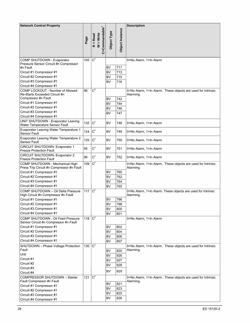
28 ED 15120-2
Network Control Property
Pag
e
R =
Rea
d
W =
Wri
te
C=
Co
mm
an
da
ble
1
Ob
jec
t T
ype
Ob
jec
t In
sta
nce
Description
BV 711
BV 713
BV 715
COMP SHUTDOWN - Evaporator Pressure Sensor Circuit #n Compressor #n Fault
Circuit #1 Compressor #1
Circuit #2 Compressor #1
Circuit #3 Compressor #1
Circuit #4 Compressor #1
105 C2
BV 716
0=No Alarm, 1=In Alarm
BV 742
BV 744
BV 746
COMP LOCKOUT - Number of Allowed Re-Starts Exceeded Circuit #n Compressor #n Fault
Circuit #1 Compressor #1
Circuit #2 Compressor #1
Circuit #3 Compressor #1
Circuit #4 Compressor #1
96 C2
BV 747
0=No Alarm, 1=In Alarm. These objects are used for Intrinsic Alarming.
UNIT SHUTDOWN - Evaporator Leaving Water Temperature Sensor Fault
132 C2 BV 748 0=No Alarm, 1=In Alarm
Evaporator Leaving Water Temperature 1 Sensor Fault
124 C2 BV 749 0=No Alarm, 1=In Alarm
Evaporator Leaving Water Temperature 2 Sensor Fault
125 C2 BV 750 0=No Alarm, 1=In Alarm
CIRCUIT SHUTDOWN- Evaporator 1 Freeze Protection Fault
95 C2 BV 751 0=No Alarm, 1=In Alarm
CIRCUIT SHUTDOWN- Evaporator 2 Freeze Protection Fault
96 C2 BV 752 0=No Alarm, 1=In Alarm
BV 760
BV 762
BV 764
COMP SHUTDOWN - Mechanical High Press Trip Circuit #n Compressor #n Fault
Circuit #1 Compressor #1
Circuit #2 Compressor #1
Circuit #3 Compressor #1
Circuit #4 Compressor #1
109 C2
BV 765
0=No Alarm, 1=In Alarm. These objects are used for Intrinsic Alarming.
BV 796
BV 798
BV 800
COMP SHUTDOWN – Oil Delta Pressure High Circuit #n Compressor #n Fault
Circuit #1 Compressor #1
Circuit #2 Compressor #1
Circuit #3 Compressor #1
Circuit #4 Compressor #1
117 C2
BV 801
0=No Alarm, 1=In Alarm. These objects are used for Intrinsic Alarming.
BV 802
BV 804
BV 806
COMP SHUTDOWN - Oil Feed Pressure Sensor Circuit #n Compressor #n Fault
Circuit #1 Compressor #1
Circuit #2 Compressor #1
Circuit #3 Compressor #1
Circuit #4 Compressor #1
118 C2
BV 807
0=No Alarm, 1=In Alarm
BV 820
BV 926
BV 927
BV 928
SHUTDOWN – Phase Voltage Protection Fault
Unit
Circuit #1
Circuit #2
Circuit #3
Circuit #4
130 C2
BV 929
0=No Alarm, 1=In Alarm. These objects are used for Intrinsic Alarming.
BV 821
BV 823
BV 825
COMPRESSOR SHUTDOWN – Starter Fault Compressor #n Fault
Circuit #1 Compressor #1
Circuit #2 Compressor #1
Circuit #3 Compressor #1
Circuit #4 Compressor #1
121 C2
BV 826
0=No Alarm, 1=In Alarm. These objects are used for Intrinsic Alarming.
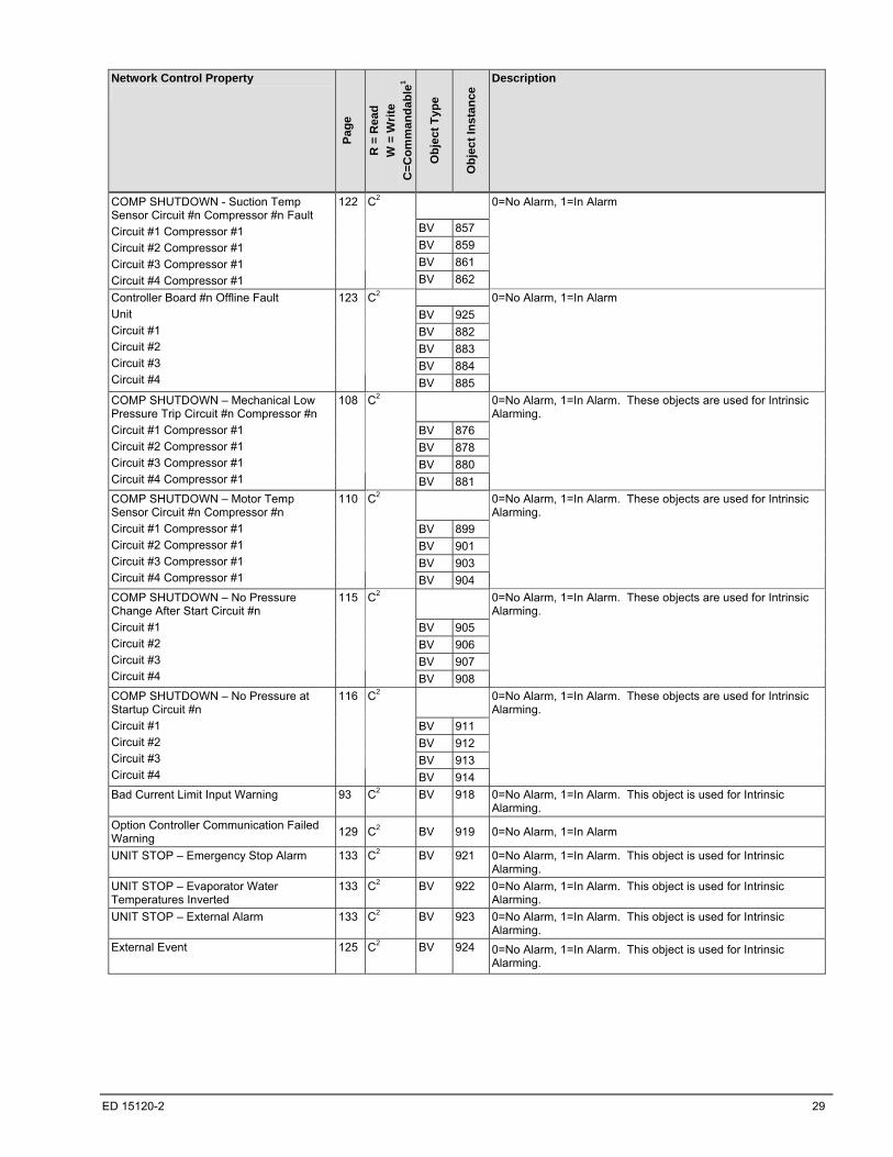
ED 15120-2 29
Network Control Property
Pag
e
R =
Rea
d
W =
Wri
te
C=
Co
mm
an
da
ble
1
Ob
jec
t T
ype
Ob
jec
t In
sta
nce
Description
BV 857
BV 859
BV 861
COMP SHUTDOWN - Suction Temp Sensor Circuit #n Compressor #n Fault
Circuit #1 Compressor #1
Circuit #2 Compressor #1
Circuit #3 Compressor #1
Circuit #4 Compressor #1
122 C2
BV 862
0=No Alarm, 1=In Alarm
BV 925
BV 882
BV 883
BV 884
Controller Board #n Offline Fault
Unit
Circuit #1
Circuit #2
Circuit #3
Circuit #4
123 C2
BV 885
0=No Alarm, 1=In Alarm
BV 876
BV 878
BV 880
COMP SHUTDOWN – Mechanical Low Pressure Trip Circuit #n Compressor #n
Circuit #1 Compressor #1
Circuit #2 Compressor #1
Circuit #3 Compressor #1
Circuit #4 Compressor #1
108 C2
BV 881
0=No Alarm, 1=In Alarm. These objects are used for Intrinsic Alarming.
BV 899
BV 901
BV 903
COMP SHUTDOWN – Motor Temp Sensor Circuit #n Compressor #n
Circuit #1 Compressor #1
Circuit #2 Compressor #1
Circuit #3 Compressor #1
Circuit #4 Compressor #1
110 C2
BV 904
0=No Alarm, 1=In Alarm. These objects are used for Intrinsic Alarming.
BV 905
BV 906
BV 907
COMP SHUTDOWN – No Pressure Change After Start Circuit #n
Circuit #1
Circuit #2
Circuit #3
Circuit #4
115 C2
BV 908
0=No Alarm, 1=In Alarm. These objects are used for Intrinsic Alarming.
BV 911
BV 912
BV 913
COMP SHUTDOWN – No Pressure at Startup Circuit #n
Circuit #1
Circuit #2
Circuit #3
Circuit #4
116 C2
BV 914
0=No Alarm, 1=In Alarm. These objects are used for Intrinsic Alarming.
Bad Current Limit Input Warning 93 C2 BV 918 0=No Alarm, 1=In Alarm. This object is used for Intrinsic Alarming.
Option Controller Communication Failed Warning
129 C2 BV 919 0=No Alarm, 1=In Alarm
UNIT STOP – Emergency Stop Alarm 133 C2 BV 921 0=No Alarm, 1=In Alarm. This object is used for Intrinsic Alarming.
UNIT STOP – Evaporator Water Temperatures Inverted
133 C2 BV 922 0=No Alarm, 1=In Alarm. This object is used for Intrinsic Alarming.
UNIT STOP – External Alarm 133 C2 BV 923 0=No Alarm, 1=In Alarm. This object is used for Intrinsic Alarming.
External Event 125 C2 BV 924 0=No Alarm, 1=In Alarm. This object is used for Intrinsic Alarming.
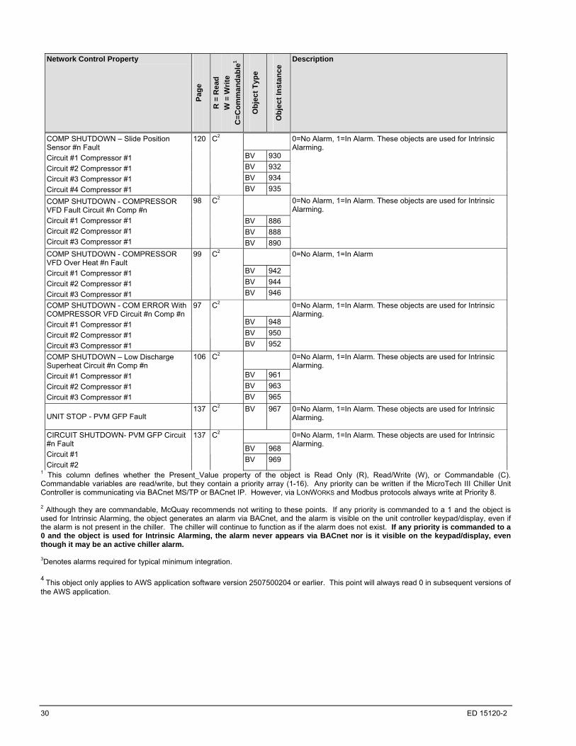
30 ED 15120-2
Network Control Property
Pag
e
R =
Rea
d
W =
Wri
te
C=
Co
mm
an
da
ble
1
Ob
jec
t T
ype
Ob
jec
t In
sta
nce
Description
BV 930
BV 932
BV 934
COMP SHUTDOWN – Slide Position Sensor #n Fault
Circuit #1 Compressor #1
Circuit #2 Compressor #1
Circuit #3 Compressor #1
Circuit #4 Compressor #1
120 C2
BV 935
0=No Alarm, 1=In Alarm. These objects are used for Intrinsic Alarming.
BV 886
BV 888
COMP SHUTDOWN - COMPRESSOR VFD Fault Circuit #n Comp #n
Circuit #1 Compressor #1
Circuit #2 Compressor #1
Circuit #3 Compressor #1
98 C2
BV 890
0=No Alarm, 1=In Alarm. These objects are used for Intrinsic Alarming.
BV 942
BV 944
COMP SHUTDOWN - COMPRESSOR VFD Over Heat #n Fault
Circuit #1 Compressor #1
Circuit #2 Compressor #1
Circuit #3 Compressor #1
99 C2
BV 946
0=No Alarm, 1=In Alarm
BV 948
BV 950
COMP SHUTDOWN - COM ERROR With COMPRESSOR VFD Circuit #n Comp #n
Circuit #1 Compressor #1
Circuit #2 Compressor #1
Circuit #3 Compressor #1
97 C2
BV 952
0=No Alarm, 1=In Alarm. These objects are used for Intrinsic Alarming.
BV 961
BV 963
COMP SHUTDOWN – Low Discharge Superheat Circuit #n Comp #n
Circuit #1 Compressor #1
Circuit #2 Compressor #1
Circuit #3 Compressor #1
106 C2
BV 965
0=No Alarm, 1=In Alarm. These objects are used for Intrinsic Alarming.
UNIT STOP - PVM GFP Fault 137 C2 BV 967 0=No Alarm, 1=In Alarm. These objects are used for Intrinsic
Alarming.
BV 968
CIRCUIT SHUTDOWN- PVM GFP Circuit #n Fault
Circuit #1
Circuit #2
137 C2
BV 969
0=No Alarm, 1=In Alarm. These objects are used for Intrinsic Alarming.
1 This column defines whether the Present_Value property of the object is Read Only (R), Read/Write (W), or Commandable (C). Commandable variables are read/write, but they contain a priority array (1-16). Any priority can be written if the MicroTech III Chiller Unit Controller is communicating via BACnet MS/TP or BACnet IP. However, via LONWORKS and Modbus protocols always write at Priority 8. 2 Although they are commandable, McQuay recommends not writing to these points. If any priority is commanded to a 1 and the object is used for Intrinsic Alarming, the object generates an alarm via BACnet, and the alarm is visible on the unit controller keypad/display, even if the alarm is not present in the chiller. The chiller will continue to function as if the alarm does not exist. If any priority is commanded to a 0 and the object is used for Intrinsic Alarming, the alarm never appears via BACnet nor is it visible on the keypad/display, even though it may be an active chiller alarm. 3Denotes alarms required for typical minimum integration. 4
This object only applies to AWS application software version 2507500204 or earlier. This point will always read 0 in subsequent versions of the AWS application.
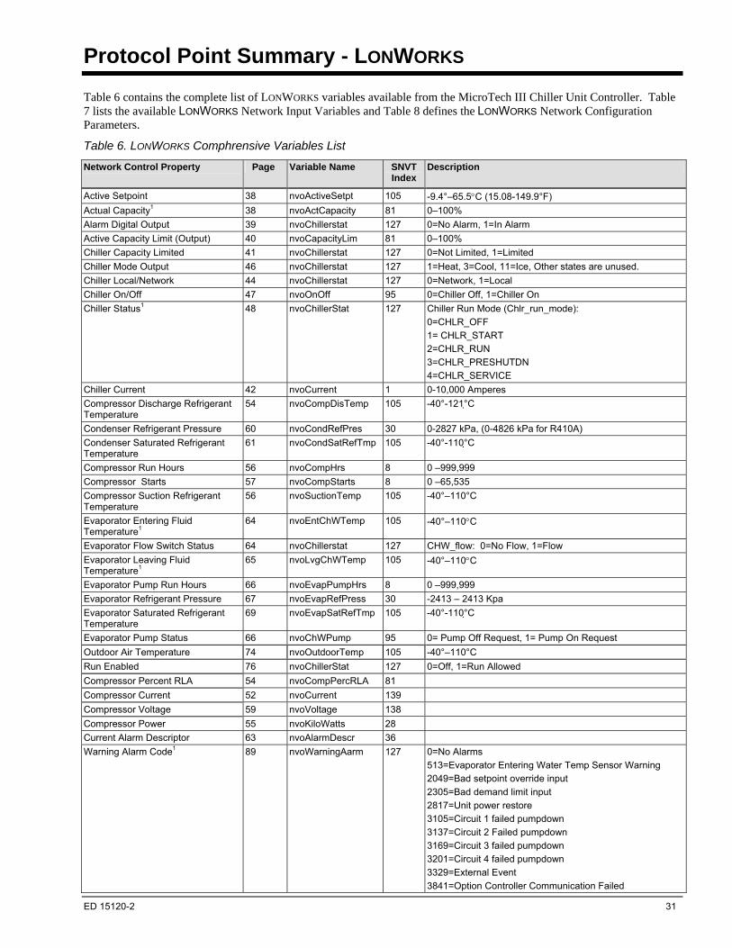
ED 15120-2 31
Protocol Point Summary - LONWORKS
Table 6 contains the complete list of LONWORKS variables available from the MicroTech III Chiller Unit Controller. Table 7 lists the available LONWORKS Network Input Variables and Table 8 defines the LONWORKS Network Configuration Parameters.
Table 6. LONWORKS Comphrensive Variables List
Network Control Property
Page Variable Name SNVT Index
Description
Active Setpoint 38 nvoActiveSetpt 105 -9.4°–65.5C (15.08-149.9°F)
Actual Capacity1 38 nvoActCapacity 81 0–100%
Alarm Digital Output 39 nvoChillerstat 127 0=No Alarm, 1=In Alarm
Active Capacity Limit (Output) 40 nvoCapacityLim 81 0–100%
Chiller Capacity Limited 41 nvoChillerstat 127 0=Not Limited, 1=Limited
Chiller Mode Output 46 nvoChillerstat 127 1=Heat, 3=Cool, 11=Ice, Other states are unused.
Chiller Local/Network 44 nvoChillerstat 127 0=Network, 1=Local
Chiller On/Off 47 nvoOnOff 95 0=Chiller Off, 1=Chiller On
Chiller Status1 48 nvoChillerStat 127 Chiller Run Mode (Chlr_run_mode):
0=CHLR_OFF
1= CHLR_START
2=CHLR_RUN
3=CHLR_PRESHUTDN
4=CHLR_SERVICE
Chiller Current 42 nvoCurrent 1 0-10,000 Amperes
Compressor Discharge Refrigerant Temperature
54 nvoCompDisTemp 105 -40°-121° C
Condenser Refrigerant Pressure 60 nvoCondRefPres 30 0-2827 kPa, (0-4826 kPa for R410A)
Condenser Saturated Refrigerant Temperature
61 nvoCondSatRefTmp 105 -40°-110° C
Compressor Run Hours 56 nvoCompHrs 8 0 –999,999
Compressor Starts 57 nvoCompStarts 8 0 –65,535
Compressor Suction Refrigerant Temperature
56 nvoSuctionTemp 105 -40°–110°C
Evaporator Entering Fluid Temperature1
64 nvoEntChWTemp 105 -40°–110C
Evaporator Flow Switch Status 64 nvoChillerstat 127 CHW_flow: 0=No Flow, 1=Flow
Evaporator Leaving Fluid Temperature1
65 nvoLvgChWTemp 105 -40°–110C
Evaporator Pump Run Hours 66 nvoEvapPumpHrs 8 0 –999,999
Evaporator Refrigerant Pressure 67 nvoEvapRefPress 30 -2413 – 2413 Kpa
Evaporator Saturated Refrigerant Temperature
69 nvoEvapSatRefTmp 105 -40°-110° C
Evaporator Pump Status 66 nvoChWPump 95 0= Pump Off Request, 1= Pump On Request
Outdoor Air Temperature 74 nvoOutdoorTemp 105 -40°–110°C
Run Enabled 76 nvoChillerStat 127 0=Off, 1=Run Allowed
Compressor Percent RLA 54 nvoCompPercRLA 81
Compressor Current 52 nvoCurrent 139
Compressor Voltage 59 nvoVoltage 138
Compressor Power 55 nvoKiloWatts 28
Current Alarm Descriptor 63 nvoAlarmDescr 36
Warning Alarm Code1 89 nvoWarningAarm 127 0=No Alarms
513=Evaporator Entering Water Temp Sensor Warning
2049=Bad setpoint override input
2305=Bad demand limit input
2817=Unit power restore
3105=Circuit 1 failed pumpdown
3137=Circuit 2 Failed pumpdown
3169=Circuit 3 failed pumpdown
3201=Circuit 4 failed pumpdown
3329=External Event
3841=Option Controller Communication Failed

32 ED 15120-2
Network Control Property
Page Variable Name SNVT Index
Description
Problems Alarm Code1 90 nvoProblemAlarm 127 0=No Alarms,
16418=RESTART DELAYED - Power Loss While Running Circuit #1
16450=RESTART DELAYED - Power Loss While Running Circuit #2
16482=RESTART DELAYED - Power Loss While Running Circuit #3
16514=RESTART DELAYED - Power Loss While Running Circuit #4
16642=START INHIBITED - Ambient Temperature Low 16898=INHIBIT LOAD–Condenser Pressure High 17186=INHIBIT LOAD–Condenser Pressure High Circuit #1
17218=INHIBIT LOAD–Condenser Pressure High Circuit #2 17250=INHIBIT LOAD–Condenser Pressure High Circuit #3 17282=INHIBIT LOAD–Condenser Pressure High Circuit #4 17698=UNLOAD - Condenser Pressure High Circuit #1 17730=UNLOAD – Condenser Pressure High Circuit #2 17762=UNLOAD – Condenser Pressure High Circuit #3 17794=UNLOAD – Condenser Pressure High Circuit #4 19490=INHIBIT LOAD - Evaporator Pressure Low Circuit #1 19522=INHIBIT LOAD - Evaporator Pressure Low Circuit #2 19554=INHIBIT LOAD - Evaporator Pressure Low Circuit #3 19586=INHIBIT LOAD - Evaporator Pressure Low Circuit #4 20002=UNLOAD - Evaporator Pressure Low Circuit #1 20034=UNLOAD - Evaporator Pressure Low Circuit #2 20066=UNLOAD - Evaporator Pressure Low Circuit #3 20098=UNLOAD - Evaporator Pressure Low Circuit #4
20262=UNLOAD-Comp Motor Current High Circuit #1, Comp #1
20294=UNLOAD-Comp Motor Current High Circuit #2, Comp #1
20326=UNLOAD-Comp Motor Current High Circuit #3, Comp #1
20738=PUMP #2 START ATTEMPTED - Evaporator Pump #1 Failure
20994=PUMP #1 START ATTEMPTED - Evaporator Pump #2 Failure
21542=INHIBIT LOAD-Comp Motor Current High Circuit #1, Comp #1
21574=INHIBIT LOAD-Comp Motor Current High Circuit #2, Comp #1
21606= INHIBIT LOAD-Comp Motor Current High Circuit #3, Comp #1
Fault Alarm Code1 90 nvoFaultAlarm 127 0=No Alarms
32551=COMP SHUTDOWN–Low pressure ratio Circuit #1, Comp #1
32583=COMP SHUTDOWN – Low pressure ratio Circuit #2, Comp #1
32615=COMP SHUTDOWN–Low pressure ratio Circuit #3, Comp #1
32647=COMP SHUTDOWN–Low pressure ratio Circuit #4, Comp #1
32771=COMP SHUTDOWN-Outside Air Temp Sensor Fault,
33063=COMP SHUTDOWN-Current Overload Trip Circuit #1, Comp #1
33095=COMP SHUTDOWN-Current Overload Trip Circuit #2, Comp #1
33127= COMP SHUTDOWN-Current Overload Trip Circuit #3, Comp #1
34087= COMP SHUTDOWN– Motor Protector Trip Circuit #1 Comp #1
34119= COMP SHUTDOWN– Motor Protector Trip Circuit #2 Comp #1
34599=COMP SHUTDOWN–Motor Temp High Circuit #1, Comp #1
34631=COMP SHUTDOWN-Motor Temp High Circuit #2,
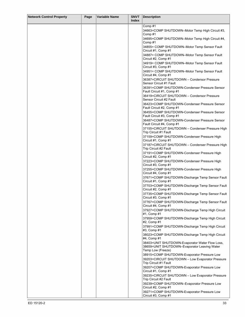
ED 15120-2 33
Network Control Property
Page Variable Name SNVT Index
Description
Comp #1
34663=COMP SHUTDOWN–Motor Temp High Circuit #3, Comp #1
34695=COMP SHUTDOWN–Motor Temp High Circuit #4, Comp #1
34855= COMP SHUTDOWN–Motor Temp Sensor Fault Circuit #1, Comp #1
34887= COMP SHUTDOWN–Motor Temp Sensor Fault Circuit #2, Comp #1
34919= COMP SHUTDOWN–Motor Temp Sensor Fault Circuit #3, Comp #1
34951= COMP SHUTDOWN–Motor Temp Sensor Fault Circuit #4, Comp #1
36387=CIRCUIT SHUTDOWN – Condensor Pressure Sensor Circuit #1 Fault
36391=COMP SHUTDOWN-Condenser Pressure Sensor Fault Circuit #1, Comp #1
36419=CIRCUIT SHUTDOWN – Condensor Pressure Sensor Circuit #2 Fault
36423=COMP SHUTDOWN-Condenser Pressure Sensor Fault Circuit #2, Comp #1
36455=COMP SHUTDOWN-Condenser Pressure Sensor Fault Circuit #3, Comp #1
36487=COMP SHUTDOWN-Condenser Pressure Sensor Fault Circuit #4, Comp #1
37155=CIRCUIT SHUTDOWN – Condenser Pressure High Trip Circuit #1 Fault
37159=COMP SHUTDOWN-Condenser Pressure High Circuit #1, Comp #1
37187=CIRCUIT SHUTDOWN – Condenser Pressure High Trip Circuit #2 Fault
37191=COMP SHUTDOWN-Condenser Pressure High Circuit #2, Comp #1
37223=COMP SHUTDOWN-Condenser Pressure High Circuit #3, Comp #1
37255=COMP SHUTDOWN-Condenser Pressure High Circuit #4, Comp #1
37671=COMP SHUTDOWN-Discharge Temp Sensor Fault Circuit #1, Comp #1
37703=COMP SHUTDOWN-Discharge Temp Sensor Fault Circuit #2, Comp #1
37735=COMP SHUTDOWN-Discharge Temp Sensor Fault Circuit #3, Comp #1
37767=COMP SHUTDOWN-Discharge Temp Sensor Fault Circuit #4, Comp #1
37927=COMP SHUTDOWN-Discharge Temp High Circuit #1, Comp #1
37959=COMP SHUTDOWN-Discharge Temp High Circuit #2, Comp #1
37991=COMP SHUTDOWN-Discharge Temp High Circuit #3, Comp #1
38023=COMP SHUTDOWN-Discharge Temp High Circuit #4, Comp #1
38403=UNIT SHUTDOWN-Evaporator Water Flow Loss, 38659=UNIT SHUTDOWN–Evaporator Leaving Water Temp Low (Freeze)
38915=COMP SHUTDOWN-Evaporator Pressure Low
39203=CIRCUIT SHUTDOWN – Low Evaporator Pressure Trip Circuit #1 Fault
39207=COMP SHUTDOWN-Evaporator Pressure Low Circuit #1, Comp #1
39235=CIRCUIT SHUTDOWN – Low Evaporator Pressure Trip Circuit #2 Fault
39239=COMP SHUTDOWN–Evaporator Pressure Low Circuit #2, Comp #1
39271=COMP SHUTDOWN-Evaporator Pressure Low Circuit #3, Comp #1
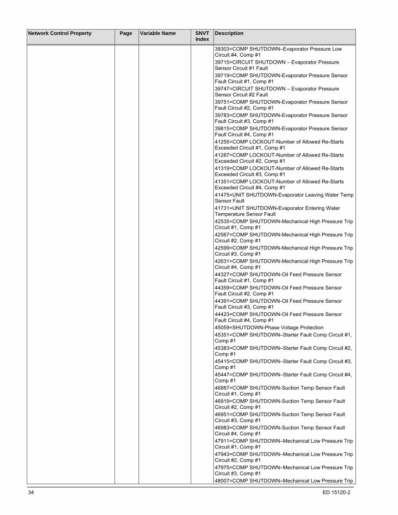
34 ED 15120-2
Network Control Property
Page Variable Name SNVT Index
Description
39303=COMP SHUTDOWN–Evaporator Pressure Low Circuit #4, Comp #1
39715=CIRCUIT SHUTDOWN – Evaporator Pressure Sensor Circuit #1 Fault
39719=COMP SHUTDOWN-Evaporator Pressure Sensor Fault Circuit #1, Comp #1
39747=CIRCUIT SHUTDOWN – Evaporator Pressure Sensor Circuit #2 Fault
39751=COMP SHUTDOWN-Evaporator Pressure Sensor Fault Circuit #2, Comp #1
39783=COMP SHUTDOWN-Evaporator Pressure Sensor Fault Circuit #3, Comp #1
39815=COMP SHUTDOWN-Evaporator Pressure Sensor Fault Circuit #4, Comp #1
41255=COMP LOCKOUT-Number of Allowed Re-Starts Exceeded Circuit #1, Comp #1
41287=COMP LOCKOUT-Number of Allowed Re-Starts Exceeded Circuit #2, Comp #1
41319=COMP LOCKOUT-Number of Allowed Re-Starts Exceeded Circuit #3, Comp #1
41351=COMP LOCKOUT-Number of Allowed Re-Starts Exceeded Circuit #4, Comp #1
41475=UNIT SHUTDOWN-Evaporator Leaving Water Temp Sensor Fault
41731=UNIT SHUTDOWN-Evaporator Entering Water Temperature Sensor Fault
42535=COMP SHUTDOWN-Mechanical High Pressure Trip Circuit #1, Comp #1
42567=COMP SHUTDOWN-Mechanical High Pressure Trip Circuit #2, Comp #1
42599=COMP SHUTDOWN-Mechanical High Pressure Trip Circuit #3, Comp #1
42631=COMP SHUTDOWN-Mechanical High Pressure Trip Circuit #4, Comp #1
44327=COMP SHUTDOWN-Oil Feed Pressure Sensor Fault Circuit #1, Comp #1
44359=COMP SHUTDOWN-Oil Feed Pressure Sensor Fault Circuit #2, Comp #1
44391=COMP SHUTDOWN-Oil Feed Pressure Sensor Fault Circuit #3, Comp #1
44423=COMP SHUTDOWN-Oil Feed Pressure Sensor Fault Circuit #4, Comp #1
45059=SHUTDOWN-Phase Voltage Protection
45351=COMP SHUTDOWN–Starter Fault Comp Circuit #1, Comp #1
45383=COMP SHUTDOWN–Starter Fault Comp Circuit #2, Comp #1
45415=COMP SHUTDOWN–Starter Fault Comp Circuit #3, Comp #1
45447=COMP SHUTDOWN–Starter Fault Comp Circuit #4, Comp #1
46887=COMP SHUTDOWN-Suction Temp Sensor Fault Circuit #1, Comp #1
46919=COMP SHUTDOWN-Suction Temp Sensor Fault Circuit #2, Comp #1
46951=COMP SHUTDOWN-Suction Temp Sensor Fault Circuit #3, Comp #1
46983=COMP SHUTDOWN-Suction Temp Sensor Fault Circuit #4, Comp #1
47911=COMP SHUTDOWN–Mechanical Low Pressure Trip Circuit #1, Comp #1
47943=COMP SHUTDOWN–Mechanical Low Pressure Trip Circuit #2, Comp #1
47975=COMP SHUTDOWN–Mechanical Low Pressure Trip Circuit #3, Comp #1
48007=COMP SHUTDOWN–Mechanical Low Pressure Trip
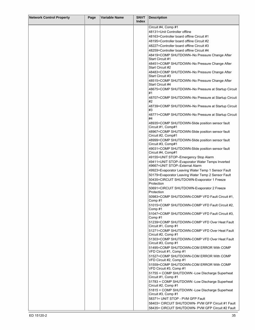
ED 15120-2 35
Network Control Property
Page Variable Name SNVT Index
Description
Circuit #4, Comp #1
48131=Unit Controller offline
48163=Controller board offline Circuit #1
48195=Controller board offline Circuit #2
48227=Controller board offline Circuit #3
48259=Controller board offline Circuit #4
48419=COMP SHUTDOWN–No Pressure Change After Start Circuit #1
48451=COMP SHUTDOWN–No Pressure Change After Start Circuit #2
48483=COMP SHUTDOWN–No Pressure Change After Start Circuit #3
48515=COMP SHUTDOWN–No Pressure Change After Start Circuit #4
48675=COMP SHUTDOWN–No Pressure at Startup Circuit #1
48707=COMP SHUTDOWN–No Pressure at Startup Circuit #2
48739=COMP SHUTDOWN–No Pressure at Startup Circuit #3
48771=COMP SHUTDOWN–No Pressure at Startup Circuit #4
48935=COMP SHUTDOWN-Slide position sensor fault Circuit #1, Comp#1
48967=COMP SHUTDOWN-Slide position sensor fault Circuit #2, Comp#1
48999=COMP SHUTDOWN-Slide position sensor fault Circuit #3, Comp#1
49031=COMP SHUTDOWN-Slide position sensor fault Circuit #4, Comp#1
49155=UNIT STOP–Emergency Stop Alarm
49411=UNIT STOP–Evaporator Water Temps Inverted 49667=UNIT STOP–External Alarm
49923=Evaporator Leaving Water Temp 1 Sensor Fault
50179=Evaporator Leaving Water Temp 2 Sensor Fault
50435=CIRCUIT SHUTDOWN-Evaporator 1 Freeze Protection
50691=CIRCUIT SHUTDOWN-Evaporator 2 Freeze Protection
50983=COMP SHUTDOWN-COMP VFD Fault Circuit #1, Comp #1
51015=COMP SHUTDOWN-COMP VFD Fault Circuit #2, Comp #1
51047=COMP SHUTDOWN-COMP VFD Fault Circuit #3, Comp #1
51239=COMP SHUTDOWN-COMP VFD Over Heat Fault Circuit #1, Comp #1
51271=COMP SHUTDOWN-COMP VFD Over Heat Fault Circuit #2, Comp #1
51303=COMP SHUTDOWN-COMP VFD Over Heat Fault Circuit #3, Comp #1
51495=COMP SHUTDOWN-COM ERROR With COMP VFD Circuit #1, Comp #1
51527=COMP SHUTDOWN-COM ERROR With COMP VFD Circuit #2, Comp #1
51559=COMP SHUTDOWN-COM ERROR With COMP VFD Circuit #3, Comp #1
51755 = COMP SHUTDOWN -Low Discharge Superheat Circuit #1, Comp #1
51783 = COMP SHUTDOWN -Low Discharge Superheat Circuit #2, Comp #1
51815 = COMP SHUTDOWN -Low Discharge Superheat Circuit #3, Comp #1
58371= UNIT STOP - PVM GFP Fault
58403= CIRCUIT SHUTDOWN- PVM GFP Circuit #1 Fault
58435= CIRCUIT SHUTDOWN- PVM GFP Circuit #2 Fault
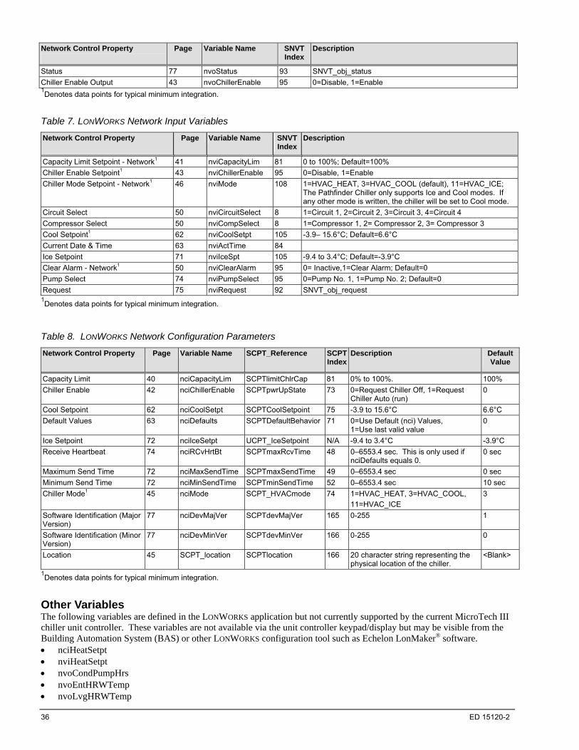
36 ED 15120-2
Network Control Property
Page Variable Name SNVT Index
Description
Status 77 nvoStatus 93 SNVT_obj_status
Chiller Enable Output 43 nvoChillerEnable 95 0=Disable, 1=Enable 1Denotes data points for typical minimum integration.
Table 7. LONWORKS Network Input Variables
Network Control Property
Page Variable Name SNVT Index
Description
Capacity Limit Setpoint - Network1 41 nviCapacityLim 81 0 to 100%; Default=100%
Chiller Enable Setpoint1 43 nviChillerEnable 95 0=Disable, 1=Enable
Chiller Mode Setpoint - Network1 46 nviMode 108 1=HVAC_HEAT, 3=HVAC_COOL (default), 11=HVAC_ICE; The Pathfinder Chiller only supports Ice and Cool modes. If any other mode is written, the chiller will be set to Cool mode.
Circuit Select 50 nviCircuitSelect 8 1=Circuit 1, 2=Circuit 2, 3=Circuit 3, 4=Circuit 4
Compressor Select 50 nviCompSelect 8 1=Compressor 1, 2= Compressor 2, 3= Compressor 3
Cool Setpoint1 62 nviCoolSetpt 105 -3.9– 15.6°C; Default=6.6°C
Current Date & Time 63 nviActTime 84
Ice Setpoint 71 nviIceSpt 105 -9.4 to 3.4°C; Default=-3.9°C
Clear Alarm - Network1 50 nviClearAlarm 95 0= Inactive,1=Clear Alarm; Default=0
Pump Select 74 nviPumpSelect 95 0=Pump No. 1, 1=Pump No. 2; Default=0
Request 75 nviRequest 92 SNVT_obj_request 1Denotes data points for typical minimum integration.
Table 8. LONWORKS Network Configuration Parameters
Network Control Property
Page Variable Name SCPT_Reference SCPT Index
Description Default Value
Capacity Limit 40 nciCapacityLim SCPTlimitChlrCap 81 0% to 100%. 100%
Chiller Enable 42 nciChillerEnable SCPTpwrUpState 73 0=Request Chiller Off, 1=Request Chiller Auto (run)
0
Cool Setpoint 62 nciCoolSetpt SCPTCoolSetpoint 75 -3.9 to 15.6°C 6.6°C
Default Values 63 nciDefaults SCPTDefaultBehavior 71 0=Use Default (nci) Values, 1=Use last valid value
0
Ice Setpoint 72 nciIceSetpt UCPT_IceSetpoint N/A -9.4 to 3.4°C -3.9°C
Receive Heartbeat 74 nciRCvHrtBt SCPTmaxRcvTime 48 0–6553.4 sec. This is only used if nciDefaults equals 0.
0 sec
Maximum Send Time 72 nciMaxSendTime SCPTmaxSendTime 49 0–6553.4 sec 0 sec
Minimum Send Time 72 nciMinSendTime SCPTminSendTime 52 0–6553.4 sec 10 sec
Chiller Mode1 45 nciMode SCPT_HVACmode 74 1=HVAC_HEAT, 3=HVAC_COOL,
11=HVAC_ICE
3
Software Identification (Major Version)
77 nciDevMajVer SCPTdevMajVer 165 0-255 1
Software Identification (Minor Version)
77 nciDevMinVer SCPTdevMinVer 166 0-255 0
Location 45 SCPT_location SCPTlocation 166 20 character string representing the physical location of the chiller.
<Blank>
1Denotes data points for typical minimum integration.
Other Variables The following variables are defined in the LONWORKS application but not currently supported by the current MicroTech III chiller unit controller. These variables are not available via the unit controller keypad/display but may be visible from the Building Automation System (BAS) or other LONWORKS configuration tool such as Echelon LonMaker® software. nciHeatSetpt nviHeatSetpt nvoCondPumpHrs nvoEntHRWTemp nvoLvgHRWTemp

ED 15120-2 37
Detailed Protocol Point Information
This section lists the information (i.e. data) that is available to the BAS via BACnet or LONWORKS communication protocols. Each data point may or may not be available on the unit controller keypad/display. If it is available, the keypad/display menu path shows one menu where this item appears. While an item may be available on several keypad menus, only one is shown. Table 9 defines the data points available for the MicroTech III chiller unit controller. Note that the points vary depending on the chiller model and corresponding unit controller application software.
Note: Data points are referred to as “properties” in the BACnet protocol and “network variables” or “configuration parameters” in the LONWORKS protocol. In this document, the text refers to this information as a “data point.” In general, the data point is applicable to both BACnet and LONWORKS. When a data point is specific to the BACnet protocol, the text refers to a “property.” When a data point is specific to the LONWORKS protocol, the text refers to a “network variable” or “configuration parameter.”
Table 9. Data Points for MicroTech III Chiller Models
Data Point AWS
(Application version 2507500204 or earlier)
AWS
(Application version 2507500205 or later)
AGZ-D
Active Setpoint X X X
Actual Capacity X X X
Alarm Digital Output X X X
Application Version X X X
Capacity Limit (LonWorks) X X X
Active Capacity Limit (Output) X X X
Capacity Limit Setpoint - Network X X X
Chiller Capacity Limited X X X
Chiller Current X X
Chiller Enable (LonWorks) X X X
Chiller Enable Output X X X
Chiller Enable Setpoint X X X
Chiller Local/Network X X X
Chiller Location X X X
Chiller Mode (LonWorks) X X X
Chiller Mode Output X X X
Chiller Mode Setpoint – Network X X X
Chiller Model X X X
Chiller On/Off X X X
Chiller Status X X X
Circuit Select X X X
Chiller Select X X X
Compressor Select X
Clear Alarm - Network X X X
Compressor Controller Communication Failed - Circuit #n X X X
Compressor Current X X
Compressor Discharge Refrigerant Temperature X X
Compressor Percent RLA X X
Compressor Power X X
Compressor Run Hours X X X
Compressor Starts X X X
Compressor Suction Refrigerant Temperature X X X
Compressor Voltage X X
Condenser Refrigerant Pressure X X X
Condenser Saturated Refrigerant Temperature X X X
Cool Setpoint – Network X X X
Cool Setpoint (LonWorks) X X X
Current Alarm Descriptor X X X
Current Date & Time X X X

38 ED 15120-2
Data Point AWS
(Application version 2507500204 or earlier)
AWS
(Application version 2507500205 or later)
AGZ-D
Default Values (LonWorks) X X X
Evaporator Entering Fluid Temperature X X X
Evaporator Flow Switch Status X X X
Evaporator Leaving Fluid Temperature X X X
Evaporator LWT #n X X
Evaporator Pump Run Hours X X X
Evaporator Pump Status X X X
Evaporator Refrigerant Pressure X X X
Evaporator Saturated Refrigerant Temperature X X X
EXV Controller Communication Failed - Circuit #n X X X
Fan Controller Communication Failed X X
Ice Setpoint - Network X X X
Ice Setpoint (LonWorks) X X X
Maximum Send Time (LonWorks) X X X
Minimum Send Time (LonWorks) X X X
Oil Feed Pressure X X
Outdoor Air Temperature X X X
Pump Select X X X
Receive Heartbeat X X X
Request X X X
Run Enabled X X X
Software Identification (Major Version) X X X
Software Identification (Minor Version) X X X
Status X X X
Units X X X
VFD Temp X X
Active Setpoint Keypad Menu Path Main Menu_Active Setpt=
This read only output network variable indicates the current setpoint used to control the chiller. The setpoint that is used is based on the operating mode (Ice, Cool or Heat) of the chiller and any “LWT reset” functions that are in effect. See “Chiller Mode Output” and “Chiller Mode Setpoint – Network”. The default mode is Cool. There are three possible setpoints. See “Cool Setpoint – Network”, “Heat Setpoint – Network” and “Ice Setpoint – Network”.
Measurement Units Data Type Usable Range Default Value
Temperature °F/°C BACnet: Real
LONWORKS: Fixed Point Scalar signed long
15.08°–149.9° F
-9.4°–65.5°C
NA
BACnet Object Identifier Property Identifier
Object Type Type Enumeration Instance Property Name Property Enumeration
Analog Value 2 5 Present Value 85
Object Name
ActiveLvgWaterTarget
LonWorks LONWORKS Name Profile SNVT Type SNVT Index SNVT Size
nvoActiveSetpt Chiller temp_p 105 two bytes
Actual Capacity Keypad Menu Path Main Menu_Unit Capacity=
This read only output network variable indicates the percent of maximum capacity the chiller is producing under the present operating conditions. At 100%, the chiller may be producing more or less than its nominal rating due to variations in operating conditions.
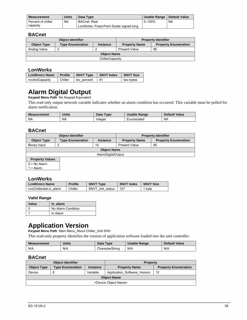
ED 15120-2 39
Measurement Units Data Type Usable Range Default Value
Percent of chiller capacity
NA BACnet: Real
LonWorks: Fixed-Point Scalar signed long
0–100% NA
BACnet Object Identifier Property Identifier
Object Type Type Enumeration Instance Property Name Property Enumeration
Analog Value 2 2 Present Value 85
Object Name
ChillerCapacity
LonWorks LONWORKS Name Profile SNVT Type SNVT Index SNVT Size
nvoActCapacity Chiller lev_percent 81 two bytes
Alarm Digital Output Keypad Menu Path No Keypad Equivalent
This read only output network variable indicates whether an alarm condition has occurred. This variable must be polled for alarm notification.
Measurement Units Data Type Usable Range Default Value
NA NA Integer Enumerated NA
BACnet Object Identifier Property Identifier
Object Type Type Enumeration Instance Property Name Property Enumeration
Binary Input 3 10 Present Value 85
Object Name
AlarmDigitalOutput
Property Values
0 = No Alarm 1 = Alarm
LonWorks LONWORKS Name Profile SNVT Type SNVT Index SNVT Size
nvoChillerstat.in_alarm Chiller SNVT_chlr_status 127 1 byte
Valid Range
Value In_alarm
0 No Alarm Condition
1 In Alarm
Application Version Keypad Menu Path Main Menu_About Chiller_Unit S/N=
This read-only property identifies the version of application software loaded into the unit controller.
Measurement Units Data Type Usable Range Default Value
N/A N/A CharacterString N/A N/A
BACnet Object Identifier Property
Object Type Type Enumeration Instance Property Name Property Enumeration
Device 8 Variable Application_Software_Version 12
Object Name
<Device Object Name>
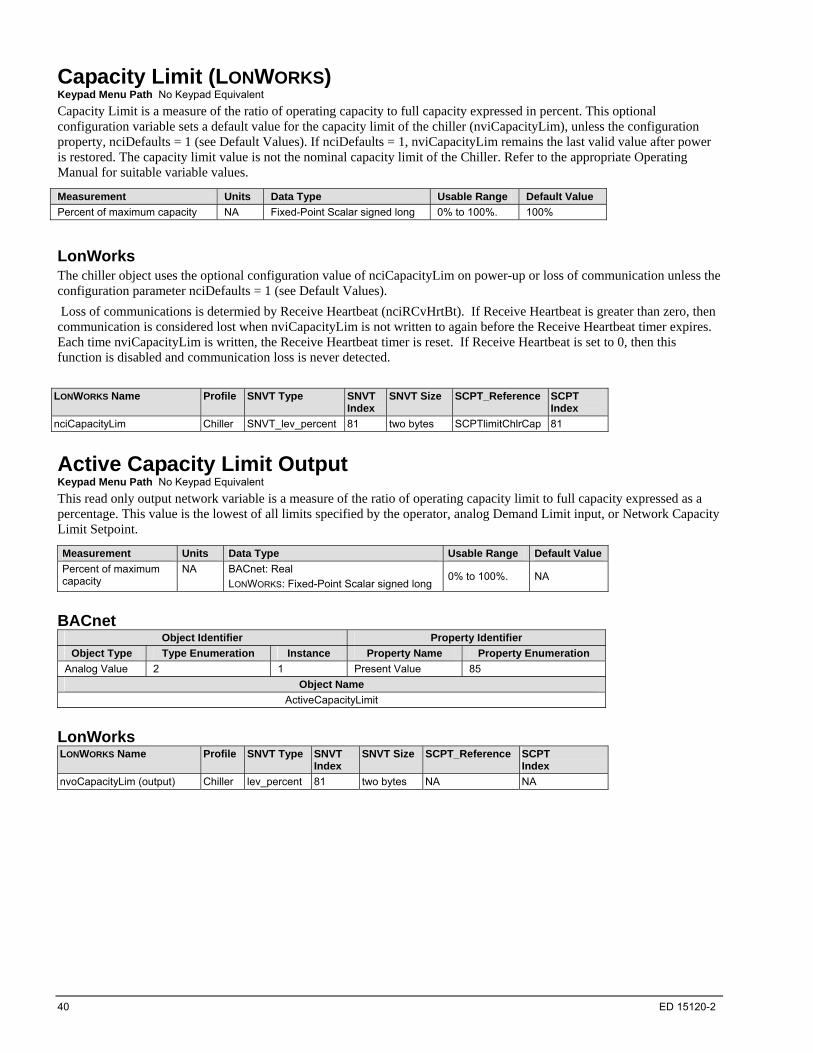
40 ED 15120-2
Capacity Limit (LONWORKS) Keypad Menu Path No Keypad Equivalent
Capacity Limit is a measure of the ratio of operating capacity to full capacity expressed in percent. This optional configuration variable sets a default value for the capacity limit of the chiller (nviCapacityLim), unless the configuration property, nciDefaults = 1 (see Default Values). If nciDefaults = 1, nviCapacityLim remains the last valid value after power is restored. The capacity limit value is not the nominal capacity limit of the Chiller. Refer to the appropriate Operating Manual for suitable variable values.
Measurement Units Data Type Usable Range Default Value
Percent of maximum capacity NA Fixed-Point Scalar signed long 0% to 100%. 100%
LonWorks The chiller object uses the optional configuration value of nciCapacityLim on power-up or loss of communication unless the configuration parameter nciDefaults = 1 (see Default Values).
Loss of communications is determied by Receive Heartbeat (nciRCvHrtBt). If Receive Heartbeat is greater than zero, then communication is considered lost when nviCapacityLim is not written to again before the Receive Heartbeat timer expires. Each time nviCapacityLim is written, the Receive Heartbeat timer is reset. If Receive Heartbeat is set to 0, then this function is disabled and communication loss is never detected.
LONWORKS Name Profile SNVT Type SNVT
Index SNVT Size SCPT_Reference SCPT
Index
nciCapacityLim Chiller SNVT_lev_percent 81 two bytes SCPTlimitChlrCap 81
Active Capacity Limit Output Keypad Menu Path No Keypad Equivalent
This read only output network variable is a measure of the ratio of operating capacity limit to full capacity expressed as a percentage. This value is the lowest of all limits specified by the operator, analog Demand Limit input, or Network Capacity Limit Setpoint.
Measurement Units Data Type Usable Range Default Value
Percent of maximum capacity
NA BACnet: Real
LONWORKS: Fixed-Point Scalar signed long 0% to 100%. NA
BACnet Object Identifier Property Identifier
Object Type Type Enumeration Instance Property Name Property Enumeration
Analog Value 2 1 Present Value 85
Object Name
ActiveCapacityLimit
LonWorks LONWORKS Name Profile SNVT Type SNVT
Index SNVT Size SCPT_Reference SCPT
Index
nvoCapacityLim (output) Chiller lev_percent 81 two bytes NA NA
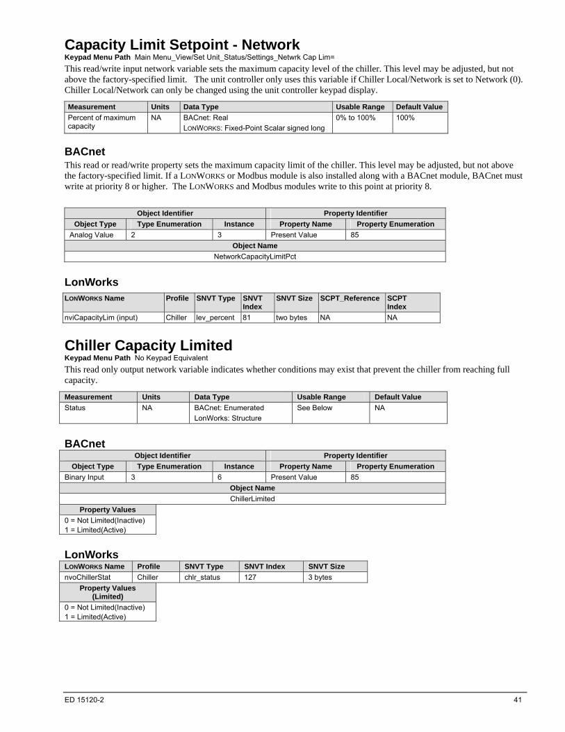
ED 15120-2 41
Capacity Limit Setpoint - Network Keypad Menu Path Main Menu_View/Set Unit_Status/Settings_Netwrk Cap Lim=
This read/write input network variable sets the maximum capacity level of the chiller. This level may be adjusted, but not above the factory-specified limit. The unit controller only uses this variable if Chiller Local/Network is set to Network (0). Chiller Local/Network can only be changed using the unit controller keypad display.
Measurement Units Data Type Usable Range Default Value
Percent of maximum capacity
NA BACnet: Real
LONWORKS: Fixed-Point Scalar signed long
0% to 100% 100%
BACnet This read or read/write property sets the maximum capacity limit of the chiller. This level may be adjusted, but not above the factory-specified limit. If a LONWORKS or Modbus module is also installed along with a BACnet module, BACnet must write at priority 8 or higher. The LONWORKS and Modbus modules write to this point at priority 8.
Object Identifier Property Identifier
Object Type Type Enumeration Instance Property Name Property Enumeration
Analog Value 2 3 Present Value 85
Object Name
NetworkCapacityLimitPct
LonWorks
LONWORKS Name Profile SNVT Type SNVT Index
SNVT Size SCPT_Reference SCPT Index
nviCapacityLim (input) Chiller lev_percent 81 two bytes NA NA
Chiller Capacity Limited Keypad Menu Path No Keypad Equivalent
This read only output network variable indicates whether conditions may exist that prevent the chiller from reaching full capacity.
Measurement Units Data Type Usable Range Default Value
Status NA BACnet: Enumerated
LonWorks: Structure
See Below NA
BACnet Object Identifier Property Identifier
Object Type Type Enumeration Instance Property Name Property Enumeration
Binary Input 3 6 Present Value 85
Object Name
ChillerLimited
Property Values
0 = Not Limited(Inactive) 1 = Limited(Active)
LonWorks LONWORKS Name Profile SNVT Type SNVT Index SNVT Size
nvoChillerStat Chiller chlr_status 127 3 bytes
Property Values (Limited)
0 = Not Limited(Inactive) 1 = Limited(Active)
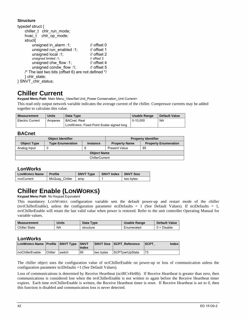
42 ED 15120-2
Structure
typedef struct { chiller_t chlr_run_mode; hvac_t chlr_op_mode; struct{ unsigned in_alarm :1; // offset 0 unsigned run_enabled :1; // offset 1 unsigned local :1; // offset 2 unsigned limited :1; // offset 3 unsigned chw_flow :1; // offset 4 unsigned condw_flow :1; // offset 5 /* The last two bits (offset 6) are not defined */ } chlr_state; } SNVT_chlr_status;
Chiller Current Keypad Menu Path Main Menu_View/Set Unit_Power Conservation_Unit Current=
This read only output network variable indicates the average current of the chiller. Compressor currents may be added together to calculate this value.
Measurement Units Data Type Usable Range Default Value
Electric Current Amperes BACnet: Real
LONWORKS: Fixed Point Scalar signed long
0-10,000 NA
BACnet Object Identifier Property Identifier
Object Type Type Enumeration Instance Property Name Property Enumeration
Analog Input 0 6 Present Value 85
Object Name
ChillerCurrent
LonWorks LONWORKS Name Profile SNVT Type SNVT Index SNVT Size
nvoCurrent McQuay_Chiller amp 1 two bytes
Chiller Enable (LONWORKS) Keypad Menu Path No Keypad Equivalent
This mandatory LONWORKS configuration variable sets the default power-up and restart mode of the chiller (nviChillerEnable), unless the configuration parameter nciDefaults = 1 (See Default Values). If nciDefaults = 1, nviChillerEnable will retain the last valid value when power is restored. Refer to the unit controller Operating Manual for variable values.
Measurement Units Data Type Usable Range Default Value
Chiller State NA structure Enumerated 0 = Disable
LonWorks LONWORKS Name Profile SNVT Type SNVT
Index SNVT Size SCPT_Reference SCPT_ Index
nciChillerEnable Chiller switch 95 two bytes SCPTpwrUpState 73
The chiller object uses the configuration value of nciChillerEnable on power-up or loss of communication unless the configuration parameter nciDefaults =1 (See Default Values).
Loss of communications is determied by Receive Heartbeat (nciRCvHrtBt). If Receive Heartbeat is greater than zero, then communications is considered lost when the nviChillerEnable is not written to again before the Receive Heartbeat timer expires. Each time nviChillerEnable is written, the Receive Heartbeat timer is reset. If Receive Heartbeat is set to 0, then this function is disabled and communication loss is never detected.

ED 15120-2 43
Valid Range
State Value Chiller Enable
0 unused Request Chiller Off
1 unused Request Chiller Auto (run)
-1 (0xff) unused Invalid
Chiller Enable Output Keypad Menu Path Main Menu_View/Set Unit_Status/Settings_Netwrk En SP=
This read only output network variable indicates if operation of the chiller is disabled or enabled. If the chiller is disabled, it cannot run. If it is enabled it is allowed to run.
Measurement Units Data Type Usable Range Default Value
Chiller State NA BACnet: Enumerated
LONWORKS: structure
See Below 0 = Disabled
BACnet This read only property indicates if operation of the chiller is disabled or enabled.
Object Identifier Property Identifier
Object Type Type Enumeration Instance Property Name Property Enumeration
Binary Input 3 7 Present Value 85
Object Name
ChillerEnableOutput
Property Values
0 = Disable(Inactive)
1 = Enable(Active)
LonWorks This output network variable indicates whether or not the chiller is enabled. LONWORKS Name Profile SNVT
Type SNVT Index
SNVT Size SCPT_Reference SCPT_ Index
nvoChillerEnable McQuay_Chiller Switch 95 two bytes NA NA
Valid Range
State Value Chiller Enable Output
0 unused Request Chiller Off
1 unused Request Chiller Auto (run)
-1 (0xff) unused Invalid
Chiller Enable Setpoint Keypad Menu Path No Keypad Equivalent
This read/write input network variable is used to disable or enable chiller operation over the network. The default is Disable. Setting this variable to Enable, does not start the chiller. It only allows the chiller to start if other operating conditions are satisfied. The unit controller only uses this variable if Chiller Local/Network is set to Network (0). Chiller Local/Network can only be changed using the unit controller keypad display.
Measurement Units Data Type Usable Range Default Value
Chiller State NA BACnet: Enumerated
LONWORKS: structure
See Below 0 = Disabled

44 ED 15120-2
BACnet Object Identifier Property Identifier
Object Type Type Enumeration Instance Property Name Property Enumeration
Binary Value 5 2 Present Value 85
Object Name
ChillerEnableStp
Property Values
0 = Disable(Inactive)
1 = Enable(Active)
LonWorks LONWORKS Name Profile SNVT Type SNVT
Index SNVT Size SCPT_Reference SCPT_Index
nviChillerEnable Chiller Switch 95 two bytes NA NA
Valid Range
State Value Chiller Enable Setpoint
0 unused Request Chiller Off
1 unused Request Chiller Auto (run)
-1 (0xff) unused Invalid
Chiller Local/Network Keypad Menu Path Main Menu_View/Set Unit_Status/Settings_Control Source=
This read only output network variable indicates whether the chiller is in local control or allowed to be controlled remotely over the network (i.e. BAS). The value can only be changed locally (i.e. unit controller keypad/display). The values from the following variables are ignored in the chiller application if this variable is set to Local (1):
Chiller Enable Setpoint Chiller Mode Setpoint – Network Cool Setpoint Network Ice Setpoint Network Capacity Limit Setpoint Clear Alarm Network
Measurement Units Data Type Usable Range Default Value
Mode NA BACnet: Enumerated
LonWorks: Structure
See Below NA
BACnet Object Identifier Property Identifier
Object Type Type Enumeration Instance Property Name Property Enumeration
Binary Input 3 3 Present Value 85
Object Name
ChillerLocalRemote
Property Values
0 = Network 1 = Local
LonWorks The LONWORKS equivalent of this data point is part of the Chiller Status output network variable. LONWORKS Name Profile SNVT Type SNVT Index SNVT Size Data Type
nvoChillerStat.local Chiller chlr_status 127 3 bytes Structure
Property Values (local)
0 = Network 1 = Local

ED 15120-2 45
Structure typedef struct { chiller_t chlr_run_mode; hvac_t chlr_op_mode; struct{ unsigned in_alarm :1; // offset 0 unsigned run_enabled :1; // offset 1 unsigned local :1; // offset 2 unsigned limited :1; // offset 3 unsigned chw_flow :1; // offset 4 unsigned condw_flow :1; // offset 5 /* The last two bits (offset 6) are not defined */ } chlr_state; } SNVT_chlr_status;
Chiller Location Keypad Menu Path No Keypad Equivalent
This read/write parameter provides a description of the physical location of the chiller. The location can be changed via the BAS. However, if the value is changed by another source, the value on the BAS is not updated until power is cycled. Changes from the BAS are written to the unit controller immediately.
Measurement Units Data Type Usable Range Default Value
NA NA Structure 20 character string maximum. Blank
BACnet Object Identifier Property Identifier
Object Type Type Enumeration Instance Property Name Property Enumeration
Device 8 Variable Location 58
Object Name
Location
LonWorks Although the LONWORKS variable is 31 bytes long, the application only allows for a 20 character string. LONWORKS Name Profile SNVT Type SNVT Index SNVT Size SCPT_Reference SCPT Index
nciLocation Chiller str_asc 36 31 bytes SCPT_location 17
Chiller Mode (LONWORKS) Keypad Menu Path No Keypad Equivalent
This optional LONWORKS configuration network parameter establishes the default operating mode of the chiller, unless the configuration parameter nciDefaults = 1 (See Default Values). If nciDefaults = 1, the last valid value is used.
Measurement Units Data Type Usable Range Default Value
HVAC Mode NA Unsigned Integer Enumerated 3 = Cool
LonWorks Chiller Mode Setpoint – Network (nviMode) is set equal to this configuration value (nciMode) on power-up or loss of communication unless the configuration parameter nciDefaults =1 (See Default Values).
Loss of communications is determied by Receive Heartbeat (nciRCvHrtBt). If Receive Heartbeat is greater than zero, then communication is considered lost if nviMode is not written to again before the Receive Heartbeat timer expires. Each time nviMode is written, the Receive Heartbeat timer is reset. If Receive Heartbeat is set to 0, then this function is disabled and communication loss is never detected.
All enumerations are not used for this data point. Only the following enumerations are used. Writing any other value from LONWORKS will result in HVAC_COOL (3) being written.
The MicroTech III Chiller Unit Controller only supports Ice and Cool modes. If any other mode is written, the chiller will be set to Cool mode.

46 ED 15120-2
LONWORKS Name Profile SNVT Type SNVT Index SNVT Size SCPT Reference SCPT Index
nciMode Chiller hvac_mode 108 one byte SCPT_HVACmode 74
Property Values
1 = HVAC_HEAT 3 = HVAC_COOL 11 = HVAC_ICE
Chiller Mode Output Keypad Menu Path Main Menu_View/Set Unit_Status/Settings_Netwrk Mode SP=
This read only output network variable indicates the current operating mode of the chiller.
Measurement Units Data Type Usable Range Default Value
HVAC Mode NA BACnet: Unsigned Integer
LONWORKS: Fixed Point Scalar - unsigned long
See Below NA
BACnet Object Identifier Property Identifier
Object Type Type Enumeration Instance Property Name Property Enumeration
Multi-state Value 19 2 Present Value 85
Object Name
ActiveMode
Property Values
1 = ICE 2 = COOL 3 = HEAT 4= COOL/HEAT RECOVERY 5=DEFROST
LonWorks The LONWORKS equivalent of this data point is part of the Chiller Status output network variable. LONWORKS Name Profile SNVT Type SNVT Index SNVT Size
nvoChillerStat Chiller chlr_status 127 3 bytes
Property Values
1= HVAC_Heat 3= HVAC_Cool 11= HVAC_Ice Other states are unused
Enumeration Correspondence
BACnet Lon
1 Ice 11 HVAC_ICE
2 Cool 3 HVAC_Cool
3 Heat 1 HVAC_Heat
4 Heat/Cool Recovery 3 HVAC_Cool
5 Defrost 1 HVAC_Heat
Chiller Mode Setpoint - Network Keypad Menu Path No Keypad Equivalent
This read/write input network variable is used to change the operating mode of the chiller. The default is Cool.
The unit controller only uses this variable if Chiller Local/Network is set to Network (0). Chiller Local/Network can only be changed using the keypad. It also only applies when Available Modes is set to Cool/Ice w/Glycol. Available Modes can also be found on the keypad.
The MicroTech III Chiller Unit Controller only supports Ice and Cool modes. If any other mode is written, the chiller will be set to Cool mode.
Measurement Units Data Type Usable Range Default Value
HVAC Mode NA BACnet: Unsigned Integer
LONWORKS: Fixed Point Scalar - unsigned long
See Below Cool

ED 15120-2 47
BACnet This commandable property sets the mode of operation of the chiller and provides the ability for another node on the network to place a chiller in another mode.
Object Identifier Property Identifier
Object Type Type Enumeration Instance Property Name Property Enumeration
Multi-state Value 19 3 Present Value 85
Object Name
ChillerOperationMode
Property Values
1 = ICE 2 = COOL 3 = HEAT 4 = COOL/HEAT RECOVERY
LonWorks This input network variable sets the mode of operation of the chiller and provides the ability for another node on the network to place a chiller in another mode. LONWORKS Name Profile SNVT Type SNVT
Index SNVT Size SCPT Reference SCPT
Index
nviMode Chiller hvac_mode 108 one byte NA NA
hvac_mode
All enumerations are not used for this data point. Only the following enumerations are used. Writing any other value from LONWORKS will result in HVAC_COOL (3) being written. Value Identifier Notes
1 HVAC_HEAT Heating only
3 HVAC_COOL Cooling only
11 HVAC_ICE Ice-making mode
Enumeration Correspondence
BACnet Lon
1 Ice 11 HVAC_ICE
2 Cool 3 HVAC_Cool
3 Heat 1 HVAC_Heat
4 Heat/Cool Recovery 3 HVAC_Cool
Chiller Model Keypad Menu Path Main Menu_About Chiller_Model #=
This BACnet read only output network variable indicates the model of the chiller.
BACnet Object Identifier Property Identifier
Object Type Type Enumeration Instance Property Name Property Enumeration
Device 8 Variable Model Name 70
Object Name
<Device Object Name>
Chiller On/Off Keypad Menu Path No Keypad Equivalent This output network variable indicates the current state of the chiller.
Measurement Units Data Type Valid Range Default Value
Chiller State NA BACnet: Enumerated
LONWORKS: structure
See Below NA
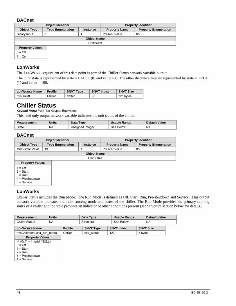
48 ED 15120-2
BACnet Object Identifier Property Identifier
Object Type Type Enumeration Instance Property Name Property Enumeration
Binary Input 3 4 Present Value 85
Object Name
UnitOnOff
Property Values
0 = Off
1 = On
LonWorks The LONWORKS equivalent of this data point is part of the Chiller Status network variable output. The OFF state is represented by state = FALSE (0) and value = 0. The other discrete states are represented by state = TRUE (1) and value = 100. LONWORKS Name Profile SNVT Type SNVT Index SNVT Size
nvoOnOff Chiller switch 95 two bytes
Chiller Status Keypad Menu Path No Keypad Equivalent
This read only output network variable indicates the unit status of the chiller.
Measurement Units Data Type Usable Range Default Value
State NA Unsigned Integer See Below NA
BACnet Object Identifier Property Identifier
Object Type Type Enumeration Instance Property Name Property Enumeration
Multi-state Value 19 1 Present Value 85
Object Name
UnitStatus
Property Values
1 = Off 2 = Start 3 = Run 4 = Preshutdown 5 = Service
LonWorks Chiller Status includes the Run Mode. The Run Mode is defined as Off, Start, Run, Pre-shutdown and Service. This output network variable indicates the main running mode and states of the chiller. The Run Mode provides the primary running states of a chiller and the state provides an indicator of other conditions present (see Structure section below for details.)
Measurement Units Data Type Usable Range Default Value
Chiller Status NA Structure See Below NA
LONWORKS Name Profile SNVT Type SNVT Index SNVT Size
nvoChillerstat.chlr_run_mode Chiller chlr_status 127 3 bytes
Property Values -1 (0xff) = Invalid (NULL) 0 = Off 1 = Start 2 = Run 3 = Preshutdown 4 = Service
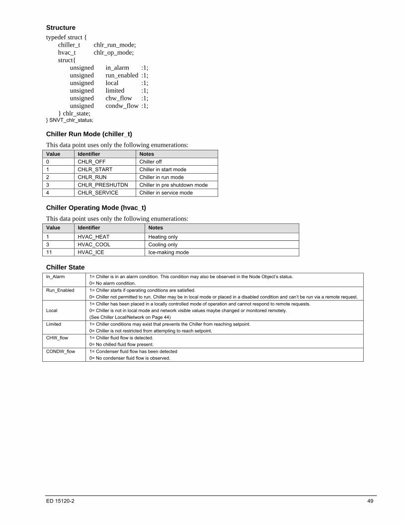
ED 15120-2 49
Structure
typedef struct { chiller_t chlr_run_mode; hvac_t chlr_op_mode; struct{ unsigned in_alarm :1; unsigned run_enabled :1; unsigned local :1; unsigned limited :1; unsigned chw_flow :1; unsigned condw_flow :1; } chlr_state; } SNVT_chlr_status;
Chiller Run Mode (chiller_t)
This data point uses only the following enumerations: Value Identifier Notes
0 CHLR_OFF Chiller off
1 CHLR_START Chiller in start mode
2 CHLR_RUN Chiller in run mode
3 CHLR_PRESHUTDN Chiller in pre shutdown mode
4 CHLR_SERVICE Chiller in service mode
Chiller Operating Mode (hvac_t)
This data point uses only the following enumerations: Value Identifier Notes
1 HVAC_HEAT Heating only
3 HVAC_COOL Cooling only
11 HVAC_ICE Ice-making mode
Chiller State In_Alarm 1= Chiller is in an alarm condition. This condition may also be observed in the Node Object’s status.
0= No alarm condition.
Run_Enabled 1= Chiller starts if operating conditions are satisfied.
0= Chiller not permitted to run. Chiller may be in local mode or placed in a disabled condition and can’t be run via a remote request.
Local
1= Chiller has been placed in a locally controlled mode of operation and cannot respond to remote requests.
0= Chiller is not in local mode and network visible values maybe changed or monitored remotely.
(See Chiller Local/Network on Page 44)
Limited 1= Chiller conditions may exist that prevents the Chiller from reaching setpoint.
0= Chiller is not restricted from attempting to reach setpoint.
CHW_flow 1= Chiller fluid flow is detected.
0= No chilled fluid flow present.
CONDW_flow 1= Condenser fluid flow has been detected
0= No condenser fluid flow is observed.
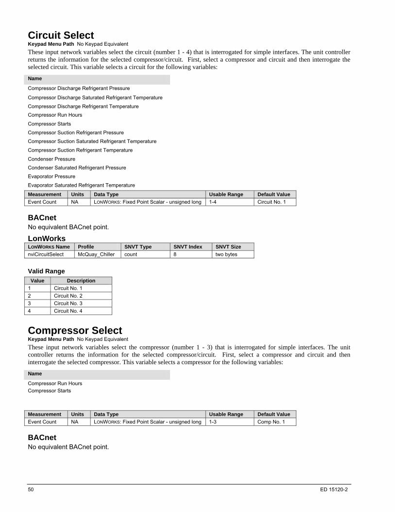
50 ED 15120-2
Circuit Select Keypad Menu Path No Keypad Equivalent
These input network variables select the circuit (number 1 - 4) that is interrogated for simple interfaces. The unit controller returns the information for the selected compressor/circuit. First, select a compressor and circuit and then interrogate the selected circuit. This variable selects a circuit for the following variables:
Name
Compressor Discharge Refrigerant Pressure
Compressor Discharge Saturated Refrigerant Temperature
Compressor Discharge Refrigerant Temperature
Compressor Run Hours
Compressor Starts
Compressor Suction Refrigerant Pressure
Compressor Suction Saturated Refrigerant Temperature
Compressor Suction Refrigerant Temperature
Condenser Pressure
Condenser Saturated Refrigerant Pressure
Evaporator Pressure
Evaporator Saturated Refrigerant Temperature
Measurement Units Data Type Usable Range Default Value
Event Count NA LONWORKS: Fixed Point Scalar - unsigned long 1-4 Circuit No. 1
BACnet No equivalent BACnet point.
LonWorks LONWORKS Name Profile SNVT Type SNVT Index SNVT Size
nviCircuitSelect McQuay_Chiller count 8 two bytes
Valid Range
Value Description
1 Circuit No. 1
2 Circuit No. 2
3 Circuit No. 3
4 Circuit No. 4
Compressor Select Keypad Menu Path No Keypad Equivalent
These input network variables select the compressor (number 1 - 3) that is interrogated for simple interfaces. The unit controller returns the information for the selected compressor/circuit. First, select a compressor and circuit and then interrogate the selected compressor. This variable selects a compressor for the following variables:
Name
Compressor Run Hours
Compressor Starts
Measurement Units Data Type Usable Range Default Value
Event Count NA LONWORKS: Fixed Point Scalar - unsigned long 1-3 Comp No. 1
BACnet No equivalent BACnet point.
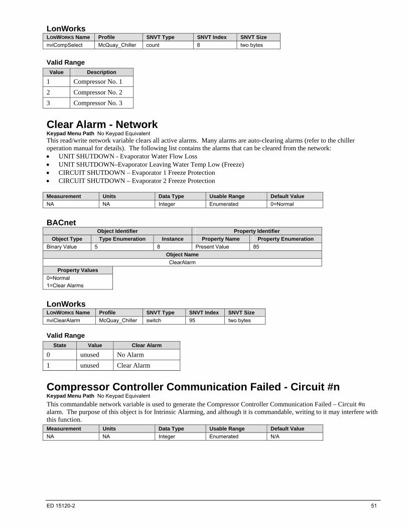
ED 15120-2 51
LonWorks LONWORKS Name Profile SNVT Type SNVT Index SNVT Size
nviCompSelect McQuay_Chiller count 8 two bytes
Valid Range
Value Description
1 Compressor No. 1
2 Compressor No. 2
3 Compressor No. 3
Clear Alarm - Network Keypad Menu Path No Keypad Equivalent This read/write network variable clears all active alarms. Many alarms are auto-clearing alarms (refer to the chiller operation manual for details). The following list contains the alarms that can be cleared from the network: UNIT SHUTDOWN - Evaporator Water Flow Loss UNIT SHUTDOWN–Evaporator Leaving Water Temp Low (Freeze) CIRCUIT SHUTDOWN – Evaporator 1 Freeze Protection CIRCUIT SHUTDOWN – Evaporator 2 Freeze Protection
Measurement Units Data Type Usable Range Default Value
NA NA Integer Enumerated 0=Normal
BACnet Object Identifier Property Identifier
Object Type Type Enumeration Instance Property Name Property Enumeration
Binary Value 5 8 Present Value 85
Object Name
ClearAlarm
Property Values
0=Normal
1=Clear Alarms
LonWorks LONWORKS Name Profile SNVT Type SNVT Index SNVT Size
nviClearAlarm McQuay_Chiller switch 95 two bytes
Valid Range
State Value Clear Alarm
0 unused No Alarm
1 unused Clear Alarm
Compressor Controller Communication Failed - Circuit #n Keypad Menu Path No Keypad Equivalent
This commandable network variable is used to generate the Compressor Controller Communication Failed – Circuit #n alarm. The purpose of this object is for Intrinsic Alarming, and although it is commandable, writing to it may interfere with this function. Measurement Units Data Type Usable Range Default Value
NA NA Integer Enumerated N/A
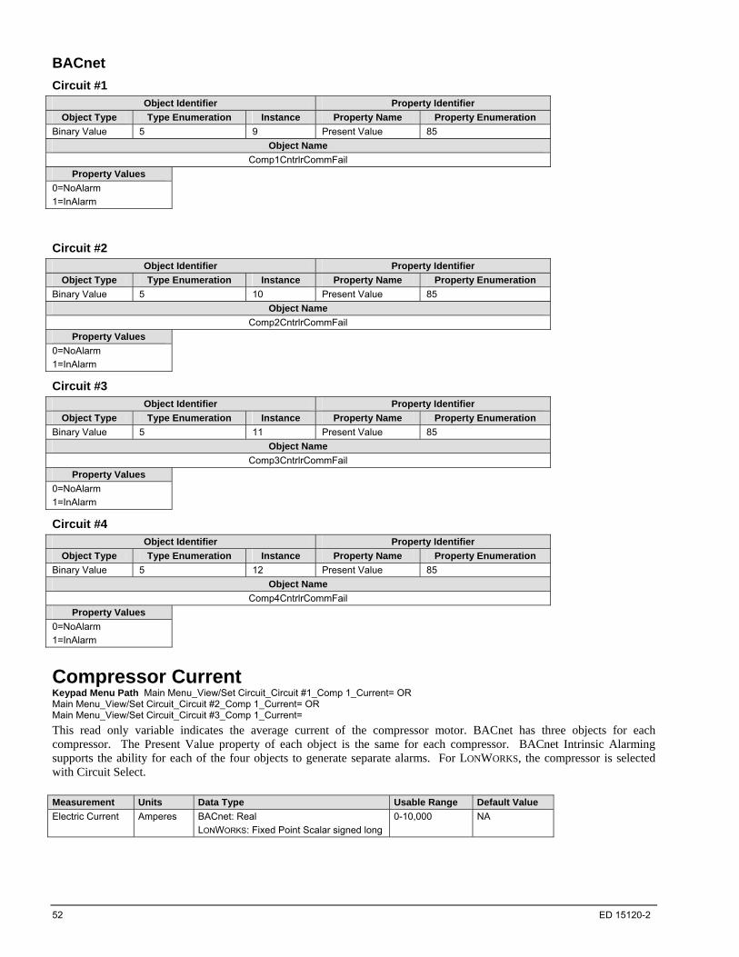
52 ED 15120-2
BACnet
Circuit #1
Object Identifier Property Identifier
Object Type Type Enumeration Instance Property Name Property Enumeration
Binary Value 5 9 Present Value 85
Object Name
Comp1CntrlrCommFail
Property Values
0=NoAlarm
1=InAlarm
Circuit #2
Object Identifier Property Identifier
Object Type Type Enumeration Instance Property Name Property Enumeration
Binary Value 5 10 Present Value 85
Object Name
Comp2CntrlrCommFail
Property Values
0=NoAlarm
1=InAlarm
Circuit #3
Object Identifier Property Identifier
Object Type Type Enumeration Instance Property Name Property Enumeration
Binary Value 5 11 Present Value 85
Object Name
Comp3CntrlrCommFail
Property Values
0=NoAlarm
1=InAlarm
Circuit #4
Object Identifier Property Identifier
Object Type Type Enumeration Instance Property Name Property Enumeration
Binary Value 5 12 Present Value 85
Object Name
Comp4CntrlrCommFail
Property Values
0=NoAlarm
1=InAlarm
Compressor Current Keypad Menu Path Main Menu_View/Set Circuit_Circuit #1_Comp 1_Current= OR Main Menu_View/Set Circuit_Circuit #2_Comp 1_Current= OR Main Menu_View/Set Circuit_Circuit #3_Comp 1_Current=
This read only variable indicates the average current of the compressor motor. BACnet has three objects for each compressor. The Present Value property of each object is the same for each compressor. BACnet Intrinsic Alarming supports the ability for each of the four objects to generate separate alarms. For LONWORKS, the compressor is selected with Circuit Select. Measurement Units Data Type Usable Range Default Value
Electric Current Amperes BACnet: Real
LONWORKS: Fixed Point Scalar signed long
0-10,000 NA

ED 15120-2 53
BACnet
Circuit #1 Compressor #1
Object Identifier Property Identifier
Object Type Type Enumeration Instance Property Name Property Enumeration
Analog Input 0 9 Present Value 85
Object Name
C1Comp1Current
Object Identifier Property Identifier
Object Type Type Enumeration Instance Property Name Property Enumeration
Analog Input 0 181 Present Value 85
Object Name
C1Co1CurrentUnl
Object Identifier Property Identifier
Object Type Type Enumeration Instance Property Name Property Enumeration
Analog Input 0 184 Present Value 85
Object Name
C1Co1CurrentHold
Circuit #2 Compressor #1
Object Identifier Property Identifier
Object Type Type Enumeration Instance Property Name Property Enumeration
Analog Input 0 12 Present Value 85
Object Name
C2Comp1Current
Object Identifier Property Identifier
Object Type Type Enumeration Instance Property Name Property Enumeration
Analog Input 0 182 Present Value 85
Object Name
C2Co1CurrentUnl
Object Identifier Property Identifier
Object Type Type Enumeration Instance Property Name Property Enumeration
Analog Input 0 185 Present Value 85
Object Name
C2Co1CurrentHold
Circuit #3 Compressor #1
Object Identifier Property Identifier
Object Type Type Enumeration Instance Property Name Property Enumeration
Analog Input 0 15 Present Value 85
Object Name
C3Comp1Current
Object Identifier Property Identifier
Object Type Type Enumeration Instance Property Name Property Enumeration
Analog Input 0 183 Present Value 85
Object Name
C3Co1CurrentUnl
Object Identifier Property Identifier
Object Type Type Enumeration Instance Property Name Property Enumeration
Analog Input 0 186 Present Value 85
Object Name
C3Co1CurrentHold
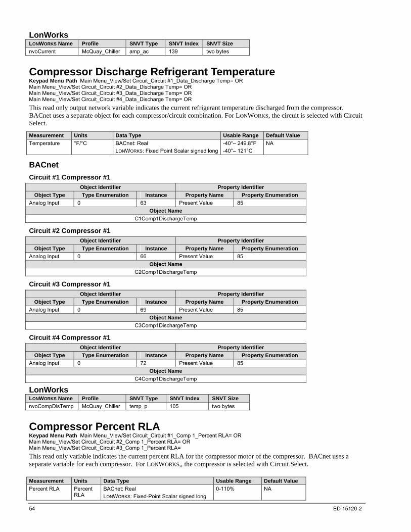
54 ED 15120-2
LonWorks LONWORKS Name Profile SNVT Type SNVT Index SNVT Size
nvoCurrent McQuay_Chiller amp_ac 139 two bytes
Compressor Discharge Refrigerant Temperature Keypad Menu Path Main Menu_View/Set Circuit_Circuit #1_Data_Discharge Temp= OR Main Menu_View/Set Circuit_Circuit #2_Data_Discharge Temp= OR Main Menu_View/Set Circuit_Circuit #3_Data_Discharge Temp= OR Main Menu_View/Set Circuit_Circuit #4_Data_Discharge Temp= OR
This read only output network variable indicates the current refrigerant temperature discharged from the compressor. BACnet uses a separate object for each compressor/circuit combination. For LONWORKS, the circuit is selected with Circuit Select.
Measurement Units Data Type Usable Range Default Value
Temperature °F/°C BACnet: Real
LONWORKS: Fixed Point Scalar signed long
-40°– 249.8°F
-40°– 121°C
NA
BACnet
Circuit #1 Compressor #1
Object Identifier Property Identifier
Object Type Type Enumeration Instance Property Name Property Enumeration
Analog Input 0 63 Present Value 85
Object Name
C1Comp1DischargeTemp
Circuit #2 Compressor #1
Object Identifier Property Identifier
Object Type Type Enumeration Instance Property Name Property Enumeration
Analog Input 0 66 Present Value 85
Object Name
C2Comp1DischargeTemp
Circuit #3 Compressor #1
Object Identifier Property Identifier
Object Type Type Enumeration Instance Property Name Property Enumeration
Analog Input 0 69 Present Value 85
Object Name
C3Comp1DischargeTemp
Circuit #4 Compressor #1
Object Identifier Property Identifier
Object Type Type Enumeration Instance Property Name Property Enumeration
Analog Input 0 72 Present Value 85
Object Name
C4Comp1DischargeTemp
LonWorks LONWORKS Name Profile SNVT Type SNVT Index SNVT Size
nvoCompDisTemp McQuay_Chiller temp_p 105 two bytes
Compressor Percent RLA Keypad Menu Path Main Menu_View/Set Circuit_Circuit #1_Comp 1_Percent RLA= OR Main Menu_View/Set Circuit_Circuit #2_Comp 1_Percent RLA= OR Main Menu_View/Set Circuit_Circuit #3_Comp 1_Percent RLA=
This read only variable indicates the current percent RLA for the compressor motor of the compressor. BACnet uses a separate variable for each compressor. For LONWORKS,, the compressor is selected with Circuit Select. Measurement Units Data Type Usable Range Default Value
Percent RLA Percent RLA
BACnet: Real
LONWORKS: Fixed-Point Scalar signed long
0-110%
NA

ED 15120-2 55
BACnet
Circuit #1 Compressor #1 - Variable Details
Object Identifier Property Identifier
Object Type Type Enumeration Instance Property Name Property Enumeration
Analog Value 2 8 Present Value 85
Object Name
C1Comp1MotorCurrentPercent
Circuit #2 Compressor #1 - Variable Details
Object Identifier Property Identifier
Object Type Type Enumeration Instance Property Name Property Enumeration
Analog Value 2 11 Present Value 85
Object Name
C2Comp1MotorCurrentPercent
Circuit #3 Compressor #1 - Variable Details
Object Identifier Property Identifier
Object Type Type Enumeration Instance Property Name Property Enumeration
Analog Value 2 14 Present Value 85
Object Name
C3Comp1MotorCurrentPercent
LonWorks LONWORKS Name Profile SNVT Type SNVT Index SNVT Size
nvoCompPercRLA McQuay_Chiller lev_percent 81 two bytes
Compressor Power Keypad Menu Path No Keypad Equivalent
This read only variable indicates the current power of the compressor motor.
BACnet uses a separate variable for each compressor. For LONWORKS, the compressor is selected with Circuit Select. Measurement Units Data Type Usable Range Default Value
Power kiloWatts BACnet: Real
LONWORKS: Unsigned Long
0-3500 NA
BACnet
Circuit #1 Compressor #1
Object Identifier Property Identifier
Object Type Type Enumeration Instance Property Name Property Enumeration
Analog Input 0 45 Present Value 85
Object Name
C1Comp1Kilowatts
Circuit #2 Compressor #1
Object Identifier Property Identifier
Object Type Type Enumeration Instance Property Name Property Enumeration
Analog Input 0 48 Present Value 85
Object Name
C2Comp1Kilowatts
Circuit #3 Compressor #1
Object Identifier Property Identifier
Object Type Type Enumeration Instance Property Name Property Enumeration
Analog Input 0 51 Present Value 85
Object Name
C3Comp1Kilowatts

56 ED 15120-2
LonWorks LONWORKS Name Profile SNVT Type SNVT Index SNVT Size
nvoKiloWattts McQuay_Chiller power_kilo 28 2 bytes
Compressor Run Hours Keypad Menu Path Main Menu_View/Set Circuit_Circuit #1_Comp 1_Run Hours=OR Main Menu_View/Set Circuit_ Circuit #1_Comp 2_Run Hours= OR Main Menu_View/Set Circuit_ Circuit #1_Comp 3_Run Hours= OR Main Menu_View/Set Circuit_ Circuit #2_Comp 1_Run Hours= OR Main Menu_View/Set Circuit_ Circuit #2_Comp 2_Run Hours= OR Main Menu_View/Set Circuit_ Circuit #2_Comp 3_Run Hours= OR Main Menu_View/Set Circuit_ Circuit #3_Comp 1_Run Hours= OR Main Menu_View/Set Circuit_ Circuit #4_Comp 1_Run Hours=
This variable indicates the number of hours that the compressor motor has been turned on. BACnet uses a separate read/write object for each compressor/circuit combination. For LONWORKS, the circuit and compressor are selected with Circuit Select and Compressor Select. With LonWorks the point is read only.
Measurement Units Data Type Usable Range Default Value
Event Count Hours BACnet: Real
LONWORKS: Float Type unsigned long
0 –999,999 NA
BACnet
Circuit #1 Compressor #1
Object Identifier Property Identifier
Object Type Type Enumeration Instance Property Name Property Enumeration
Analog Value 2 74 Present Value 85
Object Name
C1Comp1Hours
Circuit #1 Compressor #2
Object Identifier Property Identifier
Object Type Type Enumeration Instance Property Name Property Enumeration
Analog Value 2 75 Present Value 85
Object Name
C1Comp2Hours
Circuit #1 Compressor #3
Object Identifier Property Identifier
Object Type Type Enumeration Instance Property Name Property Enumeration
Analog Value 2 76 Present Value 85
Object Name
C1Comp3Hours
Circuit #2 Compressor #1
Object Identifier Property Identifier
Object Type Type Enumeration Instance Property Name Property Enumeration
Analog Value 2 77 Present Value 85
Object Name
C2Comp1Hours
Circuit #2 Compressor #2
Object Identifier Property Identifier
Object Type Type Enumeration Instance Property Name Property Enumeration
Analog Value 2 78 Present Value 85
Object Name
C2Comp2Hours

ED 15120-2 57
Circuit #2 Compressor #3
Object Identifier Property Identifier
Object Type Type Enumeration Instance Property Name Property Enumeration
Analog Value 2 79 Present Value 85
Object Name
C2Comp3Hours
Circuit #3 Compressor #1
Object Identifier Property Identifier
Object Type Type Enumeration Instance Property Name Property Enumeration
Analog Value 2 80 Present Value 85
Object Name
C3Comp1Hours
Circuit #4 Compressor #1
Object Identifier Property Identifier
Object Type Type Enumeration Instance Property Name Property Enumeration
Analog Value 2 83 Present Value 85
Object Name
C4Comp1Hours
LonWorks LONWORKS Name Profile SNVT Type SNVT Index SNVT Size
nvoCompHrs McQuay_Chiller count_f (51) 8 Two bytes
Compressor Starts Keypad Menu Path Main Menu_View/Set Circuit_ Circuit #1_Comp 1_No. Of Starts= OR Main Menu_View/Set Circuit_ Circuit #1_Comp 2_No. Of Starts= OR Main Menu_View/Set Circuit_ Circuit #1_Comp 3_No. Of Starts= OR Main Menu_View/Set Circuit_ Circuit #2_Comp 1_No. Of Starts= OR Main Menu_View/Set Circuit_ Circuit #2_Comp 2_No. Of Starts= OR Main Menu_View/Set Circuit_ Circuit #2_Comp 3_No. Of Starts= OR Main Menu_View/Set Circuit_ Circuit #3_Comp 1_No. Of Starts= OR Main Menu_View/Set Circuit_ Circuit #4_Comp 1_No. Of Starts=
This network variable indicates the number of times the compressor motor has been started. BACnet uses a separate read/write object for each compressor/circuit combination. For LONWORKS, the circuit and compressor are selected with Circuit Select and Compressor Select. With LonWorks the point is read only.
Measurement Units Data Type Usable Range Default Value
Event Count NA BACnet: Real
LONWORKS: Fixed Point Scalar - unsigned long
0 –65,535 NA
BACnet
Circuit #1 Compressor #1
Object Identifier Property Identifier
Object Type Type Enumeration Instance Property Name Property Enumeration
Analog Value 2 92 Present Value 85
Object Name
C1Comp1Starts
Circuit #1 Compressor #2
Object Identifier Property Identifier
Object Type Type Enumeration Instance Property Name Property Enumeration
Analog Value 2 93 Present Value 85
Object Name
C1Comp2Starts
Circuit #1 Compressor #3
Object Identifier Property Identifier
Object Type Type Enumeration Instance Property Name Property Enumeration
Analog Value 2 94 Present Value 85
Object Name
C1Comp3Starts

58 ED 15120-2
Circuit #2 Compressor #1
Object Identifier Property Identifier
Object Type Type Enumeration Instance Property Name Property Enumeration
Analog Value 2 95 Present Value 85
Object Name
C2Comp1Starts
Circuit #2 Compressor #2
Object Identifier Property Identifier
Object Type Type Enumeration Instance Property Name Property Enumeration
Analog Value 2 96 Present Value 85
Object Name
C2Comp2Starts
Circuit #2 Compressor #3
Object Identifier Property Identifier
Object Type Type Enumeration Instance Property Name Property Enumeration
Analog Value 2 97 Present Value 85
Object Name
C2Comp3Starts
Circuit #3 Compressor #1
Object Identifier Property Identifier
Object Type Type Enumeration Instance Property Name Property Enumeration
Analog Value 2 98 Present Value 85
Object Name
C3Comp1Starts
Circuit #4 Compressor #1
Object Identifier Property Identifier
Object Type Type Enumeration Instance Property Name Property Enumeration
Analog Value 2 101 Present Value 85
Object Name
C4Comp1Starts
LonWorks LONWORKS Name Profile SNVT
Type SNVT Index SNVT Size
nvoCompStarts McQuay_Chiller count 8 two bytes
Compressor Suction Refrigerant Temperature Keypad Menu Path Main Menu_View/Set Circuit_Circuit #1_Data_Suction Temp= OR Main Menu_View/Set Circuit_Circuit #2_Data_Suction Temp= OR Main Menu_View/Set Circuit_Circuit #3_Data_Suction Temp= OR Main Menu_View/Set Circuit_Circuit #4_Data_Suction Temp=
This read only output network variable indicates the current refrigerant temperature entering the compressor. BACnet uses a separate read-only object for each compressor/circuit combination. For LONWORKS, see Circuit Select.
Measurement Units Data Type Usable Range Default Value
Temperature °F/°C BACnet: Real
LONWORKS: Fixed Point Scalar signed long
-40°–230°F
-40°–110°C
NA
BACnet
Circuit #1 Compressor #1
Object Identifier Property Identifier
Object Type Type Enumeration Instance Property Name Property Enumeration
Analog Input 0 105 Present Value 85
Object Name
C1Comp1SuctionTemp
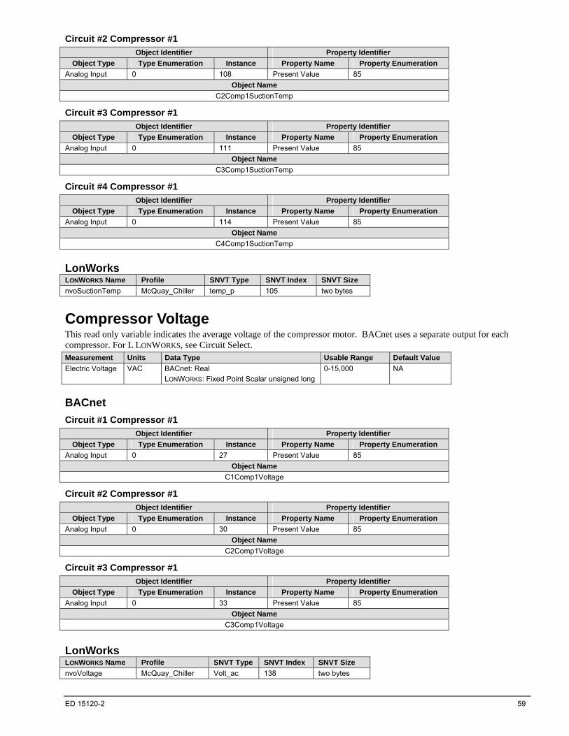
ED 15120-2 59
Circuit #2 Compressor #1
Object Identifier Property Identifier
Object Type Type Enumeration Instance Property Name Property Enumeration
Analog Input 0 108 Present Value 85
Object Name
C2Comp1SuctionTemp
Circuit #3 Compressor #1
Object Identifier Property Identifier
Object Type Type Enumeration Instance Property Name Property Enumeration
Analog Input 0 111 Present Value 85
Object Name
C3Comp1SuctionTemp
Circuit #4 Compressor #1
Object Identifier Property Identifier
Object Type Type Enumeration Instance Property Name Property Enumeration
Analog Input 0 114 Present Value 85
Object Name
C4Comp1SuctionTemp
LonWorks LONWORKS Name Profile SNVT Type SNVT Index SNVT Size
nvoSuctionTemp McQuay_Chiller temp_p 105 two bytes
Compressor Voltage This read only variable indicates the average voltage of the compressor motor. BACnet uses a separate output for each compressor. For L LONWORKS, see Circuit Select. Measurement Units Data Type Usable Range Default Value
Electric Voltage VAC BACnet: Real
LONWORKS: Fixed Point Scalar unsigned long
0-15,000
NA
BACnet
Circuit #1 Compressor #1
Object Identifier Property Identifier
Object Type Type Enumeration Instance Property Name Property Enumeration
Analog Input 0 27 Present Value 85
Object Name
C1Comp1Voltage
Circuit #2 Compressor #1
Object Identifier Property Identifier
Object Type Type Enumeration Instance Property Name Property Enumeration
Analog Input 0 30 Present Value 85
Object Name
C2Comp1Voltage
Circuit #3 Compressor #1
Object Identifier Property Identifier
Object Type Type Enumeration Instance Property Name Property Enumeration
Analog Input 0 33 Present Value 85
Object Name
C3Comp1Voltage
LonWorks LONWORKS Name Profile SNVT Type SNVT Index SNVT Size
nvoVoltage McQuay_Chiller Volt_ac 138 two bytes
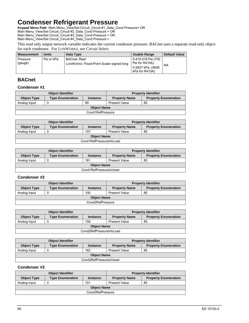
60 ED 15120-2
Condenser Refrigerant Pressure Keypad Menu Path Main Menu_View/Set Circuit_Circuit #1_Data_Cond Pressure= OR Main Menu_View/Set Circuit_Circuit #2_Data_Cond Pressure = OR Main Menu_View/Set Circuit_Circuit #3_Data_Cond Pressure = OR Main Menu_View/Set Circuit_Circuit #4_Data_Cond Pressure =
This read only output network variable indicates the current condenser pressure. BACnet uses a separate read-only object for each condenser. For LONWORKS, see Circuit Select. Measurement Units Data Type Usable Range Default Value
Pressure (gauge)
Psi or kPa BACnet: Real
LONWORKS: Fixed-Point Scalar signed long
0-410.019 Psi (700 Psi for R410A)
0-2827 kPa, (4826 kPa for R410A)
NA
BACnet
Condenser #1
Object Identifier Property Identifier
Object Type Type Enumeration Instance Property Name Property Enumeration
Analog Input 0 99 Present Value 85
Object Name
Cond1RefPressure
Object Identifier Property Identifier
Object Type Type Enumeration Instance Property Name Property Enumeration
Analog Input 0 157 Present Value 85
Object Name
Cond1RefPressureInhLoad
Object Identifier Property Identifier
Object Type Type Enumeration Instance Property Name Property Enumeration
Analog Input 0 161 Present Value 85
Object Name
Cond1RefPressureUnload
Condenser #2
Object Identifier Property Identifier
Object Type Type Enumeration Instance Property Name Property Enumeration
Analog Input 0 100 Present Value 85
Object Name
Cond2RefPressure
Object Identifier Property Identifier
Object Type Type Enumeration Instance Property Name Property Enumeration
Analog Input 0 158 Present Value 85
Object Name
Cond2RefPressureInhLoad
Object Identifier Property Identifier
Object Type Type Enumeration Instance Property Name Property Enumeration
Analog Input 0 162 Present Value 85
Object Name
Cond2RefPressureUnload
Condenser #3
Object Identifier Property Identifier
Object Type Type Enumeration Instance Property Name Property Enumeration
Analog Input 0 101 Present Value 85
Object Name
Cond3RefPressure

ED 15120-2 61
Object Identifier Property Identifier
Object Type Type Enumeration Instance Property Name Property Enumeration
Analog Input 0 159 Present Value 85
Object Name
Cond3RefPressureInhLoad
Object Identifier Property Identifier
Object Type Type Enumeration Instance Property Name Property Enumeration
Analog Input 0 163 Present Value 85
Object Name
Cond3RefPressureUnload
Condenser #4
Object Identifier Property Identifier
Object Type Type Enumeration Instance Property Name Property Enumeration
Analog Input 0 102 Present Value 85
Object Name
Cond4RefPressure
Object Identifier Property Identifier
Object Type Type Enumeration Instance Property Name Property Enumeration
Analog Input 0 160 Present Value 85
Object Name
Cond4RefPressureInhLoad
Object Identifier Property Identifier
Object Type Type Enumeration Instance Property Name Property Enumeration
Analog Input 0 164 Present Value 85
Object Name
Cond4RefPressureUnload
LonWorks LONWORKS Name Profile SNVT Type SNVT Index SNVT Size
nvoCondRefPres McQuay_Chiller SNVT_press 30 two bytes *Note: The units for SNVT_press#US is inches of water column. To display units in psi the format must be changed to SNVT_press#US_psi.
Condenser Saturated Refrigerant Temperature Keypad Menu Path Main Menu_View/Set Circuit_Circuit #1_Data_Cond Sat Temp= OR Main Menu_View/Set Circuit_Circuit #2_ Data_Cond Sat Temp = OR Main Menu_View/Set Circuit_Circuit #3_ Data_Cond Sat Temp = OR Main Menu_View/Set Circuit_Circuit #4_ Data_Cond Sat Temp =
This read only output network variable indicates the current saturated refrigerant temperature of the condenser. BACnet uses a separate read-only object for each condenser. For LONWORKS, see Circuit Select. Measurement Units Data Type Usable Range Default Value
Temperature °F/°C BACnet: Real
LONWORKS: Fixed Point Scalar signed long
-14.98-185°F
-26.1-85°C
NA
Condenser #1
Object Identifier Property Identifier
Object Type Type Enumeration Instance Property Name Property Enumeration
Analog Value 2 44 Present Value 85
Object Name
Cond1SatRefTemp
Condenser #2
Object Identifier Property Identifier
Object Type Type Enumeration Instance Property Name Property Enumeration
Analog Value 2 45 Present Value 85
Object Name
Cond2SatRefTemp

62 ED 15120-2
Condenser #3
Object Identifier Property Identifier
Object Type Type Enumeration Instance Property Name Property Enumeration
Analog Value 2 46 Present Value 85
Object Name
Cond3SatRefTemp
Condenser #4
Object Identifier Property Identifier
Object Type Type Enumeration Instance Property Name Property Enumeration
Analog Value 2 47 Present Value 85
Object Name
Cond4SatRefTemp
LonWorks LONWORKS Name Profile SNVT Type SNVT Index SNVT Size
nvoCondSatRefTmp McQuay_Chiller SNVT_temp_p 30 two bytes
Cool Setpoint - Network Keypad Menu Path Main Menu_View/Set Unit_Status/Settings_Netwrk Cool SP=
This read/write input network variable is used to change the Cooling setpoint from the network. It sets the temperature of the Leaving Chilled Fluid when the chiller is operating in the Cooling Mode. It cannot be set below the local Cool Setpoint. The default is 44°F. The unit controller only uses this variable if Chiller Local/Network is set to Network (0). Chiller Local/Network can only be changed using the keypad. The unit controller uses this variable when Chiller Mode Setpoint - Network is set to Cool (3).
Measurement Units Data Type Usable Range Default Value
Temperature °F/°C BACnet: Real
LONWORKS: Fixed Point Scalar signed long
24.98°-60.08°F
-3.9°-15.6°C
43.88°F/6.6°C
BACnet This commandable property sets the temperature of the Leaving Chilled Fluid. This level may be adjusted via an operator workstation or other network device.
Object Identifier Property Identifier
Object Type Type Enumeration Instance Property Name Property Enumeration
Analog Value 2 4 Present Value 85
Object Name
NetworkCoolTempSetpoint Note: If the BACnet communication module is attached to a unit controller that also has a LONWORKS and/or Modbus communication module attached, BACnet must write at priority 8 or higher. LONWORKS and Modbus write to this point at priority 8.
LonWorks This input network variable provides the Cooling setpoint of the Leaving Chilled Fluid when the chiller is operating in the Cooling Mode. The Cooling mode is the normal mode of chiller operation, unless overridden by using the optional Mode variable to change to another mode. LONWORKS Name Profile SNVT Type SNVT Index SNVT Size SCPT_Reference SCPT Index
nviCoolSetpt Chiller temp_p 105 two bytes NA NA
Cool Setpoint (LONWORKS) Keypad Menu Path No Keypad Equivalent
The Cool Setpoint Network variable (nviCoolSetpt) is set to this configuration value (nciCoolsetpt) on power-up or loss of communication unless the configuration parameter nciDefaults =1. If nciDefaults = 1, nviCoolSetpt will retain the last valid value when power is restored. Refer to the appropriate Operating Manual for suitable variable values. Loss of communications is determied by Receive Heartbeat (nciRCvHrtBt). If Receive Heartbeat is greater than zero, then communications is considered lost when nviCoolSetpt is not written to again before the Receive Heartbeat timer expires. Each time nviCoolSetpt is written, the Receive Heartbeat timer is reset. If Receive Heartbeat is set to 0, then this function is disabled and communication loss is never detected.
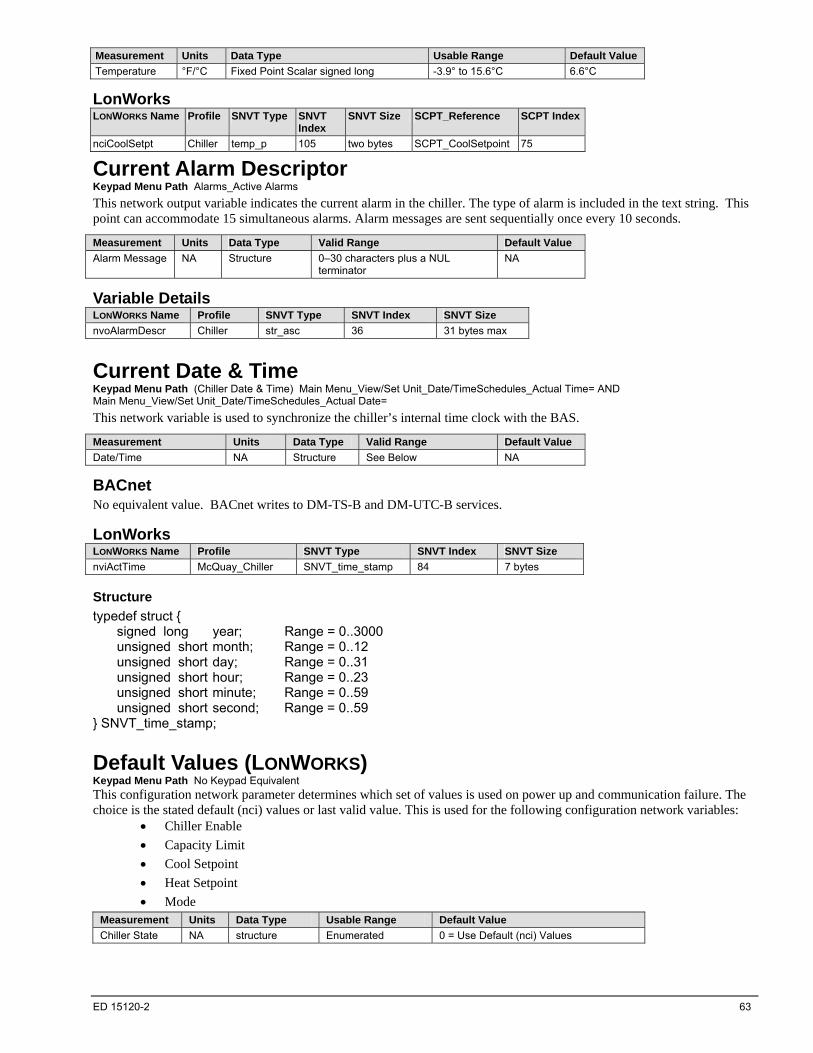
ED 15120-2 63
Measurement Units Data Type Usable Range Default Value
Temperature °F/°C Fixed Point Scalar signed long -3.9° to 15.6°C 6.6°C
LonWorks LONWORKS Name Profile SNVT Type SNVT
Index SNVT Size SCPT_Reference SCPT Index
nciCoolSetpt Chiller temp_p 105 two bytes SCPT_CoolSetpoint 75
Current Alarm Descriptor Keypad Menu Path Alarms_Active Alarms
This network output variable indicates the current alarm in the chiller. The type of alarm is included in the text string. This point can accommodate 15 simultaneous alarms. Alarm messages are sent sequentially once every 10 seconds.
Measurement Units Data Type Valid Range Default Value
Alarm Message NA Structure 0–30 characters plus a NUL terminator
NA
Variable Details LONWORKS Name Profile SNVT Type SNVT Index SNVT Size
nvoAlarmDescr Chiller str_asc 36 31 bytes max
Current Date & Time Keypad Menu Path (Chiller Date & Time) Main Menu_View/Set Unit_Date/TimeSchedules_Actual Time= AND Main Menu_View/Set Unit_Date/TimeSchedules_Actual Date=
This network variable is used to synchronize the chiller’s internal time clock with the BAS.
Measurement Units Data Type Valid Range Default Value
Date/Time NA Structure See Below NA
BACnet No equivalent value. BACnet writes to DM-TS-B and DM-UTC-B services.
LonWorks LONWORKS Name Profile SNVT Type SNVT Index SNVT Size
nviActTime McQuay_Chiller SNVT_time_stamp 84 7 bytes
Structure
typedef struct { signed long year; Range = 0..3000 unsigned short month; Range = 0..12 unsigned short day; Range = 0..31 unsigned short hour; Range = 0..23 unsigned short minute; Range = 0..59 unsigned short second; Range = 0..59 } SNVT_time_stamp;
Default Values (LONWORKS) Keypad Menu Path No Keypad Equivalent This configuration network parameter determines which set of values is used on power up and communication failure. The choice is the stated default (nci) values or last valid value. This is used for the following configuration network variables:
Chiller Enable
Capacity Limit
Cool Setpoint
Heat Setpoint
Mode Measurement Units Data Type Usable Range Default Value
Chiller State NA structure Enumerated 0 = Use Default (nci) Values

64 ED 15120-2
LonWorks LONWORKS Name Profile SNVT Type SNVT Index SNVT Size SCPT_Reference SCPT Index
nciDefaults Chiller switch 95 two bytes SCPT_DefaultBehavior 71
Valid Range Value Field unused
State Field 0 Use Default (nci) Values
1 Use last valid value
Evaporator Entering Fluid Temperature Keypad Menu Path Main Menu_Evaporator EWT=
This read-only output network variable indicates the temperature of the fluid entering the evaporator.
Measurement Units Data Type Usable Range Default Value
Temperature °F/°C BACnet: Real
LONWORKS: Fixed Point Scalar signed long
-40–230°F
-40°–110C
NA
BACnet Object Identifier Property Identifier
Object Type Type Enumeration Instance Property Name Property Enumeration
Analog Input 0 1 Present Value 85
Object Name
EntEvapWaterTemp
LonWorks LONWORKS Name Profile SNVT Type SNVT Index SNVT Size
nvoEntChWTemp Chiller temp_p 105 two bytes
Evaporator Flow Switch Status Keypad Menu Path No Keypad Equivalent
This read-only output network indicates the status of the fluid flowing through the evaporator.
Measurement Units Data Type Usable Range Default Value
Flow State NA BACnet: Enumerated
LONWORKS: Structure
See Below NA
BACnet Object Identifier Property Identifier
Object Type Type Enumeration Instance Property Name Property Enumeration
Binary Input 3 2 Present Value 85
Object Name
EvapWaterFlowStatus
Property Values
0 = No Flow(Inactive)
1 = Flow(Active)
LonWorks LONWORKS Name Profile SNVT Type SNVT Index SNVT Size
nvoChillerstat.CHW_flow Chiller chlr_status 127 3 bytes
Property Values
(CHW_flow)
0 = No Flow(Inactive)
1 = Flow(Active)

ED 15120-2 65
Structure
typedef struct { chiller_t chlr_run_mode; hvac_t chlr_op_mode; struct{ unsigned in_alarm :1; // offset 0 unsigned run_enabled :1; // offset 1 unsigned local :1; // offset 2 unsigned limited :1; // offset 3 unsigned chw_flow :1; // offset 4 unsigned condw_flow :1; // offset 5 /* The last two bits (offset 6) are not defined */ } chlr_state; } SNVT_chlr_status;
Evaporator Leaving Fluid Temperature Keypad Menu Path Main Menu_Evaporator LWT=
This read-only output network variable indicates the current temperature of the fluid leaving the evaporator.
Measurement Units Data Type Usable Range Default Value
Temperature °F/°C BACnet: Real
LONWORKS: Fixed Point Scalar signed long
-40–230°F
-40°–110C
NA
BACnet Object Identifier Property Identifier
Object Type Type Enumeration Instance Property Name Property Enumeration
Analog Input 0 2 Present Value 85
Object Name
LvgEvapWaterTempUnit
LonWorks LONWORKS Name Profile SNVT Type SNVT Index SNVT Size
nvoLvgChWTemp Chiller temp_p 105 two bytes
Evaporator LWT #n This object is present only for Intrinsic Alarming. It generates the Evaporator Leaving Water Temperature #n Sensor Fault and CIRCUIT SHUTDOWN - Evaporator #n Freeze Protection alarms. Measurement Units Data Type Usable Range Default Value
Temperature °F/°C BACnet: Real N/A NA
BACnet
Evap LWT #1
Object Identifier Property Identifier
Object Type Type Enumeration Instance Property Name Property Enumeration
Analog Input 0 151 Present Value 85
Object Name
EvapLWT1
Evap LWT #2
Object Identifier Property Identifier
Object Type Type Enumeration Instance Property Name Property Enumeration
Analog Input 0 152 Present Value 85
Object Name
EvapLWT2
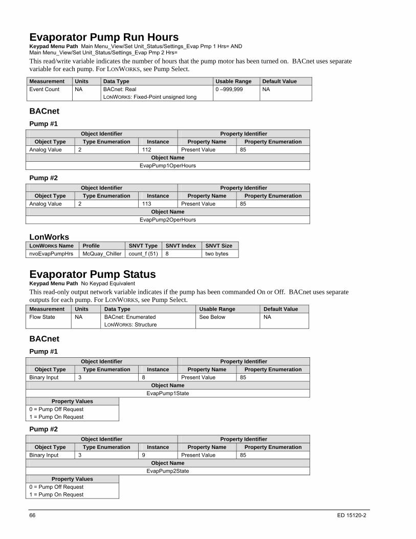
66 ED 15120-2
Evaporator Pump Run Hours Keypad Menu Path Main Menu_View/Set Unit_Status/Settings_Evap Pmp 1 Hrs= AND Main Menu_View/Set Unit_Status/Settings_Evap Pmp 2 Hrs=
This read/write variable indicates the number of hours that the pump motor has been turned on. BACnet uses separate variable for each pump. For LONWORKS, see Pump Select.
Measurement Units Data Type Usable Range Default Value
Event Count NA BACnet: Real
LONWORKS: Fixed-Point unsigned long
0 –999,999 NA
BACnet
Pump #1
Object Identifier Property Identifier
Object Type Type Enumeration Instance Property Name Property Enumeration
Analog Value 2 112 Present Value 85
Object Name
EvapPump1OperHours
Pump #2
Object Identifier Property Identifier
Object Type Type Enumeration Instance Property Name Property Enumeration
Analog Value 2 113 Present Value 85
Object Name
EvapPump2OperHours
LonWorks LONWORKS Name Profile SNVT Type SNVT Index SNVT Size
nvoEvapPumpHrs McQuay_Chiller count_f (51) 8 two bytes
Evaporator Pump Status Keypad Menu Path No Keypad Equivalent
This read-only output network variable indicates if the pump has been commanded On or Off. BACnet uses separate outputs for each pump. For LONWORKS, see Pump Select. Measurement Units Data Type Usable Range Default Value
Flow State NA BACnet: Enumerated
LONWORKS: Structure
See Below NA
BACnet
Pump #1
Object Identifier Property Identifier
Object Type Type Enumeration Instance Property Name Property Enumeration
Binary Input 3 8 Present Value 85
Object Name
EvapPump1State
Property Values
0 = Pump Off Request
1 = Pump On Request
Pump #2
Object Identifier Property Identifier
Object Type Type Enumeration Instance Property Name Property Enumeration
Binary Input 3 9 Present Value 85
Object Name
EvapPump2State
Property Values
0 = Pump Off Request
1 = Pump On Request

ED 15120-2 67
LonWorks LONWORKS Name Profile SNVT Type SNVT Index SNVT Size
nvoChWPump McQuay_Chiller switch 95 two bytes
Valid Range
State Value Pump Status
0 unused Pump Off Request
1 unused Pump On Request
Evaporator Refrigerant Pressure Keypad Menu Path Main Menu_View/Set Circuit_Circuit #1_Data_Evap Pressure= AND Main Menu_View/Set/Circuit_Circuit #2_Data_Evap Pressure= AND Main Menu_View/Set/Circuit_Circuit #3_Data_Evap Pressure= AND Main Menu_View/Set/Circuit_Circuit #4_Data_Evap Pressure= AND
This read-only variable indicates the current refrigerant pressure in the evaporator. BACnet has four objects for each compressor. The Present Value property of each object is the same for each compressor. BACnet Intrinsic Alarming supports the ability for each of the four objects to generate separate alarms. For LONWORKS, see Circuit Select.
Measurement Units Data Type Usable Range Default Value
Pressure (gauge)
Psi or kPa BACnet: Real
LONWORKS: Fixed-Point Scalar signed long
-349.974–349.974 psi
-2413 kPa – 2413 kPa
NA
BACnet
Evaporator #1
Object Identifier Property Identifier
Object Type Type Enumeration Instance Property Name Property Enumeration
Analog Input 0 141 Present Value 85
Object Name
C1EvapRefPressure
Object Identifier Property Identifier
Object Type Type Enumeration Instance Property Name Property Enumeration
Analog Input 0 153 Present Value 85
Object Name
C1EvapRefPressureUnload
Object Identifier Property Identifier
Object Type Type Enumeration Instance Property Name Property Enumeration
Analog Input 0 169 Present Value 85
Object Name
C1EvapRefPressureStrtFail
Object Identifier Property Identifier
Object Type Type Enumeration Instance Property Name Property Enumeration
Analog Input 0 173 Present Value 85
Object Name
C1EvapRefPressureInhLoad
Evaporator #2
Object Identifier Property Identifier
Object Type Type Enumeration Instance Property Name Property Enumeration
Analog Input 0 142 Present Value 85
Object Name
C2EvapRefPressure

68 ED 15120-2
Object Identifier Property Identifier
Object Type Type Enumeration Instance Property Name Property Enumeration
Analog Input 0 154 Present Value 85
Object Name
C2EvapRefPressureUnload
Object Identifier Property Identifier
Object Type Type Enumeration Instance Property Name Property Enumeration
Analog Input 0 170 Present Value 85
Object Name
C2EvapRefPressureStrtFail
Object Identifier Property Identifier
Object Type Type Enumeration Instance Property Name Property Enumeration
Analog Input 0 174 Present Value 85
Object Name
C2EvapRefPressureInhLoad
Evaporator #3
Object Identifier Property Identifier
Object Type Type Enumeration Instance Property Name Property Enumeration
Analog Input 0 143 Present Value 85
Object Name
C3EvapRefPressure
Object Identifier Property Identifier
Object Type Type Enumeration Instance Property Name Property Enumeration
Analog Input 0 155 Present Value 85
Object Name
C3EvapRefPressureUnload
Object Identifier Property Identifier
Object Type Type Enumeration Instance Property Name Property Enumeration
Analog Input 0 171 Present Value 85
Object Name
C3EvapRefPressureStrtFail
Object Identifier Property Identifier
Object Type Type Enumeration Instance Property Name Property Enumeration
Analog Input 0 175 Present Value 85
Object Name
C3EvapRefPressureInhLoad
Evaporator #4
Object Identifier Property Identifier
Object Type Type Enumeration Instance Property Name Property Enumeration
Analog Input 0 144 Present Value 85
Object Name
C4EvapRefPressure
Object Identifier Property Identifier
Object Type Type Enumeration Instance Property Name Property Enumeration
Analog Input 0 156 Present Value 85
Object Name
C4EvapRefPressureUnload

ED 15120-2 69
Object Identifier Property Identifier
Object Type Type Enumeration Instance Property Name Property Enumeration
Analog Input 0 172 Present Value 85
Object Name
C4EvapRefPressureStrtFail
Object Identifier Property Identifier
Object Type Type Enumeration Instance Property Name Property Enumeration
Analog Input 0 176 Present Value 85
Object Name
C4EvapRefPressureInhLoad
LonWorks LONWORKS Name Profile SNVT Type SNVT Index SNVT Size
nvoEvapRefPress McQuay_Chiller SNVT_press 30 two bytes *Note: The units for SNVT_press#US is inches of water column. To display units in psi the format must be changed to SNVT_press#US_psi.
Evaporator Saturated Refrigerant Temperature Keypad Menu Path Main Menu_View/Set Circuit_Circuit #1_Data_Evap Sat Temp= AND Main Menu_View/Set Circuit _Circuit #2_Data_Evap Sat Temp= AND Main Menu_View/Set Circuit _Circuit #3_Data_Evap Sat Temp= AND Main Menu_View/Set Circuit _Circuit #4_Data_Evap Sat Temp=
This read only output network parameter indicates the current saturated refrigerant temperature of the evaporator. For BACnet, there is a separate output for each condenser. For LONWORKS, see Circuit Select.
Measurement Units Data Type Usable Range Default Value
Temperature °F/°C BACnet: Real
LONWORKS: Fixed Point Scalar signed long
-14.98-185°F
-26.1-85°C
NA
BACnet
Evaporator #1
Object Identifier Property Identifier
Object Type Type Enumeration Instance Property Name Property Enumeration
Analog Value 2 68 Present Value 85
Object Name
C1EvapSatRefTemp
Evaporator #2
Object Identifier Property Identifier
Object Type Type Enumeration Instance Property Name Property Enumeration
Analog Value 2 69 Present Value 85
Object Name
C2EvapSatRefTemp
Evaporator #3
Object Identifier Property Identifier
Object Type Type Enumeration Instance Property Name Property Enumeration
Analog Value 2 70 Present Value 85
Object Name
C3EvapSatRefTemp
Evaporator #4
Object Identifier Property Identifier
Object Type Type Enumeration Instance Property Name Property Enumeration
Analog Value 2 71 Present Value 85
Object Name
C4EvapSatRefTemp
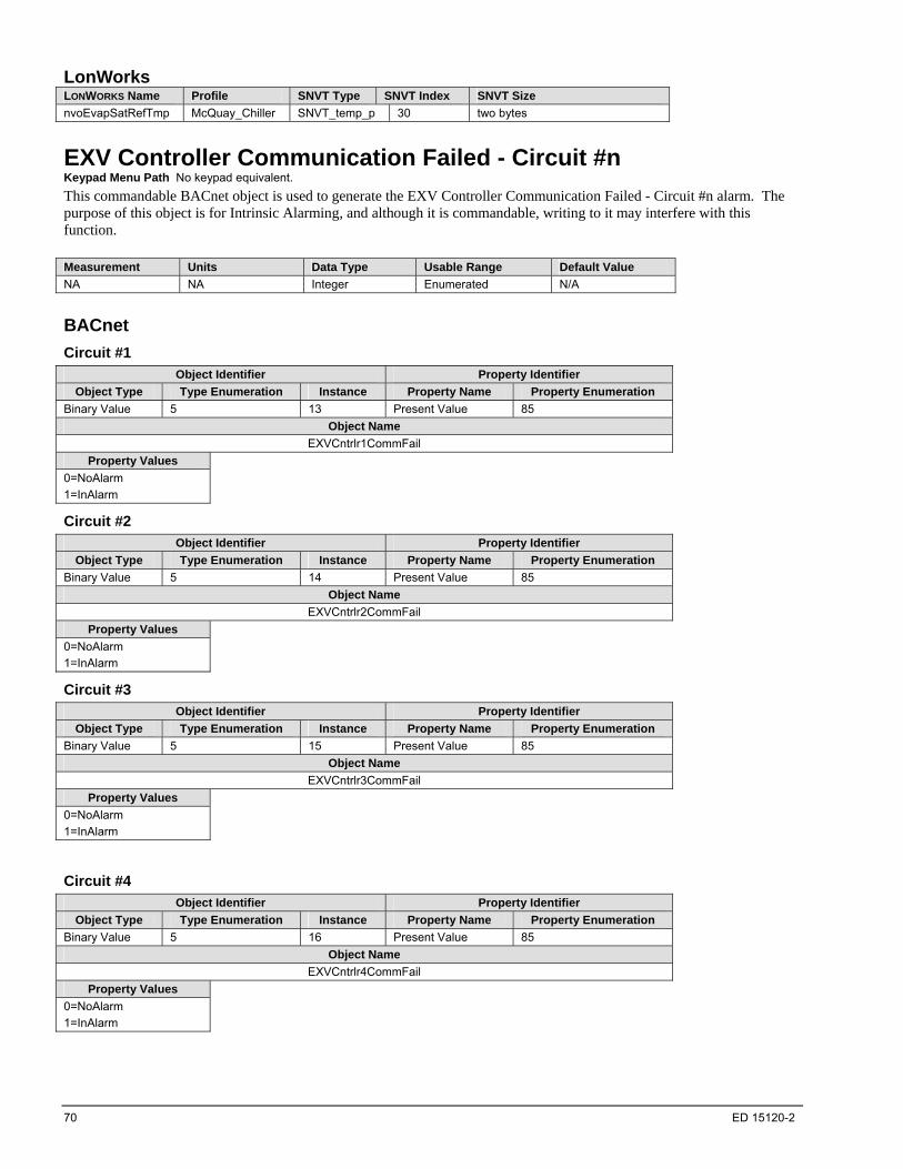
70 ED 15120-2
LonWorks LONWORKS Name Profile SNVT Type SNVT Index SNVT Size
nvoEvapSatRefTmp McQuay_Chiller SNVT_temp_p 30 two bytes
EXV Controller Communication Failed - Circuit #n Keypad Menu Path No keypad equivalent.
This commandable BACnet object is used to generate the EXV Controller Communication Failed - Circuit #n alarm. The purpose of this object is for Intrinsic Alarming, and although it is commandable, writing to it may interfere with this function. Measurement Units Data Type Usable Range Default Value
NA NA Integer Enumerated N/A
BACnet
Circuit #1
Object Identifier Property Identifier
Object Type Type Enumeration Instance Property Name Property Enumeration
Binary Value 5 13 Present Value 85
Object Name
EXVCntrlr1CommFail
Property Values
0=NoAlarm
1=InAlarm
Circuit #2
Object Identifier Property Identifier
Object Type Type Enumeration Instance Property Name Property Enumeration
Binary Value 5 14 Present Value 85
Object Name
EXVCntrlr2CommFail
Property Values
0=NoAlarm
1=InAlarm
Circuit #3
Object Identifier Property Identifier
Object Type Type Enumeration Instance Property Name Property Enumeration
Binary Value 5 15 Present Value 85
Object Name
EXVCntrlr3CommFail
Property Values
0=NoAlarm
1=InAlarm
Circuit #4
Object Identifier Property Identifier
Object Type Type Enumeration Instance Property Name Property Enumeration
Binary Value 5 16 Present Value 85
Object Name
EXVCntrlr4CommFail
Property Values
0=NoAlarm
1=InAlarm
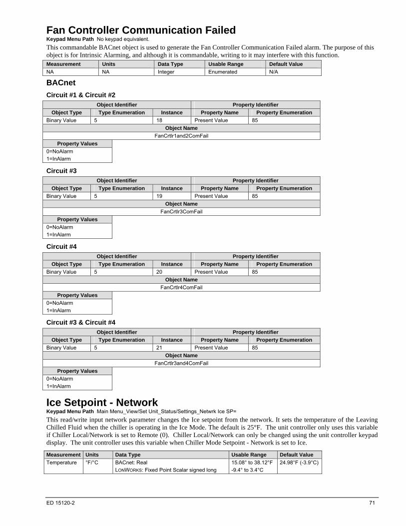
ED 15120-2 71
Fan Controller Communication Failed Keypad Menu Path No keypad equivalent.
This commandable BACnet object is used to generate the Fan Controller Communication Failed alarm. The purpose of this object is for Intrinsic Alarming, and although it is commandable, writing to it may interfere with this function. Measurement Units Data Type Usable Range Default Value
NA NA Integer Enumerated N/A
BACnet
Circuit #1 & Circuit #2
Object Identifier Property Identifier
Object Type Type Enumeration Instance Property Name Property Enumeration
Binary Value 5 18 Present Value 85
Object Name
FanCrtlr1and2ComFail
Property Values
0=NoAlarm
1=InAlarm
Circuit #3
Object Identifier Property Identifier
Object Type Type Enumeration Instance Property Name Property Enumeration
Binary Value 5 19 Present Value 85
Object Name
FanCrtlr3ComFail
Property Values
0=NoAlarm
1=InAlarm
Circuit #4
Object Identifier Property Identifier
Object Type Type Enumeration Instance Property Name Property Enumeration
Binary Value 5 20 Present Value 85
Object Name
FanCrtlr4ComFail
Property Values
0=NoAlarm
1=InAlarm
Circuit #3 & Circuit #4
Object Identifier Property Identifier
Object Type Type Enumeration Instance Property Name Property Enumeration
Binary Value 5 21 Present Value 85
Object Name
FanCrtlr3and4ComFail
Property Values
0=NoAlarm
1=InAlarm
Ice Setpoint - Network Keypad Menu Path Main Menu_View/Set Unit_Status/Settings_Netwrk Ice SP=
This read/write input network parameter changes the Ice setpoint from the network. It sets the temperature of the Leaving Chilled Fluid when the chiller is operating in the Ice Mode. The default is 25°F. The unit controller only uses this variable if Chiller Local/Network is set to Remote (0). Chiller Local/Network can only be changed using the unit controller keypad display. The unit controller uses this variable when Chiller Mode Setpoint - Network is set to Ice.
Measurement Units Data Type Usable Range Default Value
Temperature °F/°C BACnet: Real
LONWORKS: Fixed Point Scalar signed long
15.08° to 38.12°F
-9.4° to 3.4°C
24.98°F (-3.9°C)
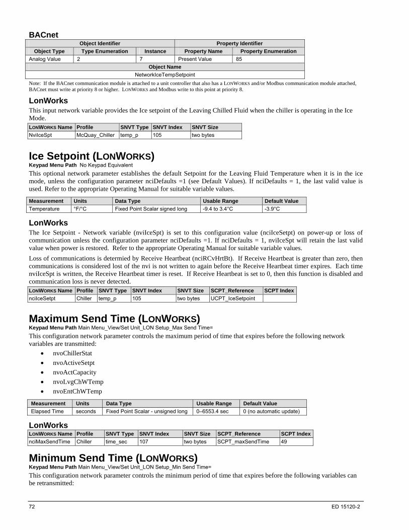
72 ED 15120-2
BACnet Object Identifier Property Identifier
Object Type Type Enumeration Instance Property Name Property Enumeration
Analog Value 2 7 Present Value 85
Object Name
NetworkIceTempSetpoint
Note: If the BACnet communication module is attached to a unit controller that also has a LONWORKS and/or Modbus communication module attached, BACnet must write at priority 8 or higher. LONWORKS and Modbus write to this point at priority 8.
LonWorks This input network variable provides the Ice setpoint of the Leaving Chilled Fluid when the chiller is operating in the Ice Mode. LONWORKS Name Profile SNVT Type SNVT Index SNVT Size
NviIceSpt McQuay_Chiller temp_p 105 two bytes
Ice Setpoint (LONWORKS) Keypad Menu Path No Keypad Equivalent
This optional network parameter establishes the default Setpoint for the Leaving Fluid Temperature when it is in the ice mode, unless the configuration parameter nciDefaults =1 (see Default Values). If nciDefaults = 1, the last valid value is used. Refer to the appropriate Operating Manual for suitable variable values.
Measurement Units Data Type Usable Range Default Value
Temperature °F/°C Fixed Point Scalar signed long -9.4 to 3.4°C -3.9°C
LonWorks The Ice Setpoint - Network variable (nviIceSpt) is set to this configuration value (nciIceSetpt) on power-up or loss of communication unless the configuration parameter nciDefaults =1. If nciDefaults = 1, nviIceSpt will retain the last valid value when power is restored. Refer to the appropriate Operating Manual for suitable variable values.
Loss of communications is determied by Receive Heartbeat (nciRCvHrtBt). If Receive Heartbeat is greater than zero, then communications is considered lost of the nvi is not written to again before the Receive Heartbeat timer expires. Each time nviIceSpt is written, the Receive Heartbeat timer is reset. If Receive Heartbeat is set to 0, then this function is disabled and communication loss is never detected. LONWORKS Name Profile SNVT Type SNVT Index SNVT Size SCPT_Reference SCPT Index
nciIceSetpt Chiller temp_p 105 two bytes UCPT_IceSetpoint
Maximum Send Time (LONWORKS) Keypad Menu Path Main Menu_View/Set Unit_LON Setup_Max Send Time=
This configuration network parameter controls the maximum period of time that expires before the following network variables are transmitted:
nvoChillerStat
nvoActiveSetpt
nvoActCapacity
nvoLvgChWTemp
nvoEntChWTemp
Measurement Units Data Type Usable Range Default Value
Elapsed Time seconds Fixed Point Scalar - unsigned long 0–6553.4 sec 0 (no automatic update)
LonWorks LONWORKS Name Profile SNVT Type SNVT Index SNVT Size SCPT_Reference SCPT Index
nciMaxSendTime Chiller time_sec 107 two bytes SCPT_maxSendTime 49
Minimum Send Time (LONWORKS) Keypad Menu Path Main Menu_View/Set Unit_LON Setup_Min Send Time=
This configuration network parameter controls the minimum period of time that expires before the following variables can be retransmitted:

ED 15120-2 73
nvoActCapacity nvoCapacityLim nvoCompDisTemp nvoCondRefPres nvoCondSatRefTmp nvoEntChWTemp nvoEvapRefPress nvoEvapSatRefTmp nvoLvgChWTemp nvoOutdoorTemp nvoSuctionTemp
Measurement Units Data Type Usable Range Default Value
Elapsed Time seconds Fixed Point Scalar - unsigned long 0–6553.4 sec 10 seconds
LonWorks LONWORKS Name Profile SNVT Type SNVT Index SNVT Size SCPT_Reference SCPT Index
nciMinSendTime Chiller time_sec 107 two bytes SCPT_minSendTime 52
Oil Feed Pressure Keypad Menu Path No Keypad Equivalent
This commandable BACnet object indicates the current Oil Feed Pressure. There is one BACnet object for each compressor. These objects are used for Intrinsic Alarming and generate the COMPRESSOR SHUTDOWN - Oil Feed Pressure Sensor Fault Circuit #n Comp #n alarms. The purpose of this object is for Intrinsic Alarming, and although it is commandable, writing to it will interfere with this function.
Measurement Units Data Type Usable Range Default Value
Pressure (gauge) Psi or kPa BACnet: Real -5.801473 to 17.54946 psi
-40 to 121kPA
NA
BACnet
Circuit #1 Compressor #1
Object Identifier Property Identifier
Object Type Type Enumeration Instance Property Name Property Enumeration
Analog Input 0 165 Present Value 85
Object Name
C1Comp1OilFeedPress
Circuit #2 Compressor #1
Object Identifier Property Identifier
Object Type Type Enumeration Instance Property Name Property Enumeration
Analog Input 0 166 Present Value 85
Object Name
C2Comp1OilFeedPress
Circuit #3 Compressor #1
Object Identifier Property Identifier
Object Type Type Enumeration Instance Property Name Property Enumeration
Analog Input 0 167 Present Value 85
Object Name
C3Comp1OilFeedPress
Circuit #4 Compressor #1
Object Identifier Property Identifier
Object Type Type Enumeration Instance Property Name Property Enumeration
Analog Input 0 168 Present Value 85
Object Name
C4Comp1OilFeedPress
LonWorks No LONWORKS equivalent.
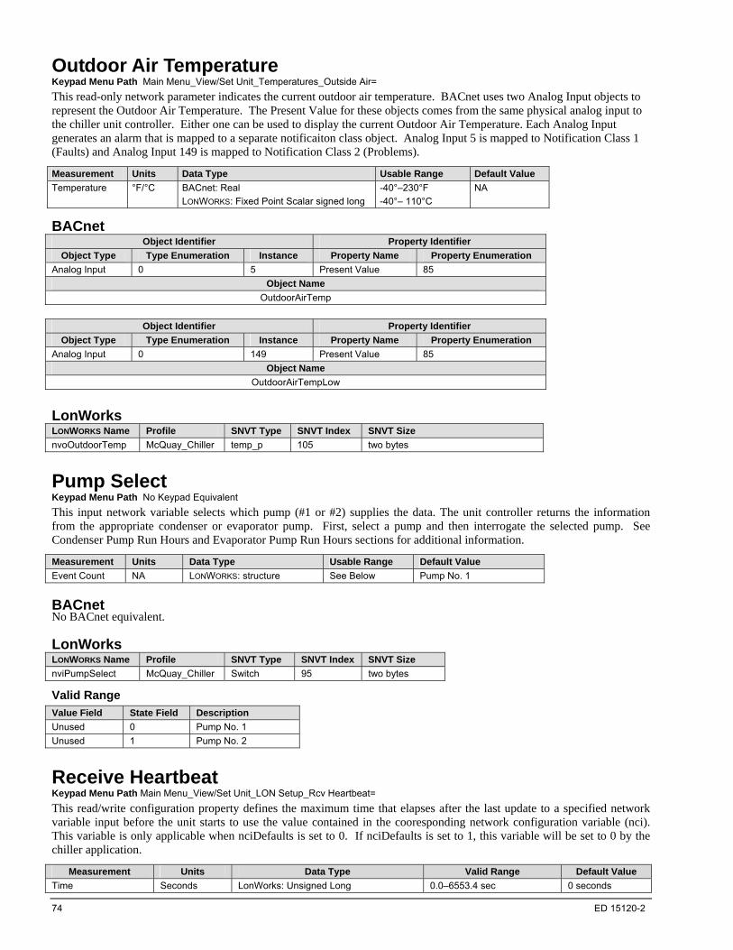
74 ED 15120-2
Outdoor Air Temperature Keypad Menu Path Main Menu_View/Set Unit_Temperatures_Outside Air=
This read-only network parameter indicates the current outdoor air temperature. BACnet uses two Analog Input objects to represent the Outdoor Air Temperature. The Present Value for these objects comes from the same physical analog input to the chiller unit controller. Either one can be used to display the current Outdoor Air Temperature. Each Analog Input generates an alarm that is mapped to a separate notificaiton class object. Analog Input 5 is mapped to Notification Class 1 (Faults) and Analog Input 149 is mapped to Notification Class 2 (Problems).
Measurement Units Data Type Usable Range Default Value
Temperature °F/°C BACnet: Real
LONWORKS: Fixed Point Scalar signed long
-40°–230°F
-40°– 110°C
NA
BACnet Object Identifier Property Identifier
Object Type Type Enumeration Instance Property Name Property Enumeration
Analog Input 0 5 Present Value 85
Object Name
OutdoorAirTemp
Object Identifier Property Identifier
Object Type Type Enumeration Instance Property Name Property Enumeration
Analog Input 0 149 Present Value 85
Object Name
OutdoorAirTempLow
LonWorks LONWORKS Name Profile SNVT Type SNVT Index SNVT Size
nvoOutdoorTemp McQuay_Chiller temp_p 105 two bytes
Pump Select Keypad Menu Path No Keypad Equivalent
This input network variable selects which pump (#1 or #2) supplies the data. The unit controller returns the information from the appropriate condenser or evaporator pump. First, select a pump and then interrogate the selected pump. See Condenser Pump Run Hours and Evaporator Pump Run Hours sections for additional information.
Measurement Units Data Type Usable Range Default Value
Event Count NA LONWORKS: structure See Below Pump No. 1
BACnet No BACnet equivalent.
LonWorks LONWORKS Name Profile SNVT Type SNVT Index SNVT Size
nviPumpSelect McQuay_Chiller Switch 95 two bytes
Valid Range
Value Field State Field Description
Unused 0 Pump No. 1
Unused 1 Pump No. 2
Receive Heartbeat Keypad Menu Path Main Menu_View/Set Unit_LON Setup_Rcv Heartbeat=
This read/write configuration property defines the maximum time that elapses after the last update to a specified network variable input before the unit starts to use the value contained in the cooresponding network configuration variable (nci). This variable is only applicable when nciDefaults is set to 0. If nciDefaults is set to 1, this variable will be set to 0 by the chiller application.
Measurement Units Data Type Valid Range Default Value
Time Seconds LonWorks: Unsigned Long 0.0–6553.4 sec 0 seconds
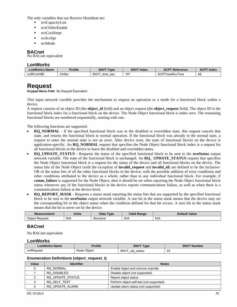
ED 15120-2 75
The only variables that use Receive Heartbeat are: nviCapacityLim nviChillerEnable nviCoolSetpt nviIceSpt nviMode
BACnet No BACnet equivalent
LonWorks LONWORKS Name Profile SNVT Type SNVT Index SCPT Reference SCPT Index
nciRCvHrtBt Chiller SNVT_time_sec 107 SCPTmaxRcvTime 48
Request Keypad Menu Path No Keypad Equivalent This input network variable provides the mechanism to request an operation or a mode for a functional block within a device. A request consists of an object ID (the object_id field) and an object request (the object_request field). The object ID is the functional block index for a functional block on the device. The Node Object functional block is index zero. The remaining functional blocks are numbered sequentially, starting with one. The following functions are supported: RQ_NORMAL - If the specified functional block was in the disabled or overridden state, this request cancels that
state, and returns the functional block to normal operation. If the functional block was already in the normal state, a request to enter the normal state is not an error. After device reset, the state of functional blocks on the device is application-specific. An RQ_NORMAL request that specifies the Node Object functional block index is a request for all functional blocks in the device to leave the disabled and overridden states.
RQ_UPDATE_STATUS - Requests the status of the specified functional block to be sent to the nvoStatus output network variable. The state of the functional block is unchanged. An RQ_ UPDATE_STATUS request that specifies the Node Object functional block is a request for the status of the device and all functional blocks on the device. The status bits of the Node Object (with the exception of invalid_request and invalid_id) are defined to be the inclusive-OR of the status bits of all the other functional blocks in the device; with the possible addition of error conditions and other conditions attributed to the device as a whole, rather than to any individual functional block. For example, if comm_failure is supported for the Node Object, then it should be set when reporting the Node Object functional block status whenever any of the functional blocks in the device reports communications failure, as well as when there is a communications failure at the device level.
RQ_REPORT_MASK - Requests a status mask reporting the status bits that are supported by the specified functional block to be sent to the nvoStatus output network variable. A one bit in the status mask means that the device may set the corresponding bit in the object status when the condition defined for that bit occurs. A zero bit in the status mask means that the bit is never set by the device.
Measurement Units Data Type Valid Range Default Value
Object Request N/A Structure N/A N/A
BACnet
No BACnet equivalent
LonWorks LonWorks Name Profile SNVT Type SNVT Number
nviRequest Node Object SNVT_obj_status 93
Enumeration Definitions (object_request_t)
Value Identifier Notes
0 RQ_NORMAL Enable object and remove override
1 RQ_DISABLED Disable object (not supported)
2 RQ_UPDATE_STATUS Report object status
3 RQ_SELF_TEST Perform object self-test (not supported)
4 RQ_UPDATE_ALARM Update alarm status (not supported)
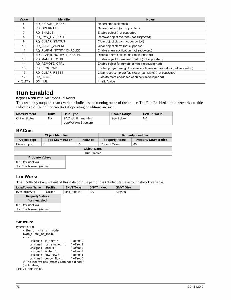
76 ED 15120-2
Value Identifier Notes
5 RQ_REPORT_MASK Report status bit mask
6 RQ_OVERRIDE Override object (not supported)
7 RQ_ENABLE Enable object (not supported)
8 RQ_RMV_OVERRIDE Remove object override (not supported)
9 RQ_CLEAR_STATUS Clear object status (not supported)
10 RQ_CLEAR_ALARM Clear object alarm (not supported)
11 RQ_ALARM_NOTIFY_ENABLED Enable alarm notification (not supported)
12 RQ_ALARM_NOTIFY_DISABLED Disable alarm notification (not supported)
13 RQ_MANUAL_CTRL Enable object for manual control (not supported)
14 RQ_REMOTE_CTRL Enable object for remote control (not supported)
15 RQ_PROGRAM Enable programming of special configuration properties (not supported)
16 RQ_CLEAR_RESET Clear reset-complete flag (reset_complete) (not supported)
17 RQ_RESET Execute reset-sequence of object (not supported)
-1(0xFF) OC_NUL Invalid Value
Run Enabled Keypad Menu Path No Keypad Equivalent
This read only output network variable indicates the running mode of the chiller. The Run Enabled output network variable indicates that the chiller can start if operating conditions are met.
Measurement Units Data Type Usable Range Default Value
Chiller Status NA BACnet: Enumerated
LONWORKS: Structure
See Below NA
BACnet Object Identifier Property Identifier
Object Type Type Enumeration Instance Property Name Property Enumeration
Binary Input 3 5 Present Value 85
Object Name
RunEnabled
Property Values
0 = Off (Inactive)
1 = Run Allowed (Active)
LonWorks The LONWORKS equivalent of this data point is part of the Chiller Status output network variable. LONWORKS Name Profile SNVT Type SNVT Index SNVT Size
nvoChillerStat Chiller chlr_status 127 3 bytes
Property Values
(run_enabled)
0 = Off (Inactive)
1 = Run Allowed (Active)
Structure typedef struct { chiller_t chlr_run_mode; hvac_t chlr_op_mode; struct{ unsigned in_alarm :1; // offset 0 unsigned run_enabled :1; // offset 1 unsigned local :1; // offset 2 unsigned limited :1; // offset 3 unsigned chw_flow :1; // offset 4 unsigned condw_flow :1; // offset 5 /* The last two bits (offset 6) are not defined */ } chlr_state; } SNVT_chlr_status;

ED 15120-2 77
Software Identification (Major Version) Keypad Menu Path No Keypad Equivalent
This property displays the major revision number for the chiller LONWORKS communication module firmware.
Measurement Units Data Type Usable Range Default Value
Version Number NA Structure 0-255 1
LonWorks LonWorks Name Profile SCPT Reference SCPT Number SCPT Size
nciDevMajVer Node Object SCPTdevMajVer 165 1 byte
Software Identification (Minor Version) Keypad Menu Path No Keypad Equivalent
This configuration property displays the minor revision number for the chiller LONWORKS communication module firmware.
Measurement Units Data Type Usable Range Default Value
Version Number NA Structure 0-255 0
LonWorks LonWorks Name Profile SCPT Reference SCPT Number SCPT Size
nciDevMinVer Node Object SCPTdevMinVer 166 1 byte
Status Keypad Menu Path No Keypad Equivalent This output network variable reports the status for any functional block on a device. It is also used to report the status of the entire device and all functional blocks on the device. A status update consists of an object ID (the object_id field) and multiple status fields. The object ID is the functional block index as described under nviRequest. If the object ID is zero, the status of the device itself and all functional blocks on the device is reported. The status fields are one-bit bitfields. The only supported status fields are the report_mask, invalid_id, and invalid_request fields; all other status fields are not supported. invalid_request - Set to one if an unsupported request code is received on the nviRequest input network variable. invalid_id - Set to one if a request is received for a functional block index that is not defined in the device. No further
checking of the request code is required when set to one. report_mask - Set to one if an RQ_REPORT_MASK request is received by the nviRequest input network variable,
and the nvoStatus output network variable is set to contain the status mask. The status mask is an nvoStatus value that describes the status bits that are supported beyond the three mandatory status bits. The status mask consists of all fields in the nvoStatus output network variable, with the exception of the report_mask, invalid_id, and invalid_request fields. A one bit in the mask means that the functional block may set the corresponding bit in the nvoStatus output network variable when the condition defined for that bit occurs. A zero bit means that the functional block may never set the bit.
Measurement Units Data Type Valid Range Default Value
Object Status N/A Structure N/A N/A
BACnet
No BACnet equivalent
LonWorks LonWorks Name Profile SNVT Type SNVT Number
nvoStatus Node Object SNVT_obj_request 92
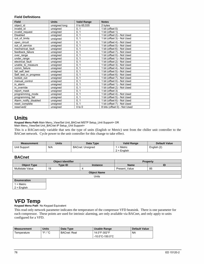
78 ED 15120-2
Field Definitions
Field Units Valid Range Notes object_id unsigned long 0 to 65,535 2 bytes invalid_id unsigned 0, 1 1 bit (offset 0) invalid_request unsigned 0, 1 1 bit (offset 1) Disabled unsigned 0, 1 1 bit (offset 2) - Not Used out_of_limits unsigned 0, 1 1 bit (offset 3) - Not Used
open_circuit unsigned 0, 1 1 bit (offset 4) - Not Used out_of_service unsigned 0, 1 1 bit (offset 5) - Not Used mechanical_fault unsigned 0, 1 1 bit (offset 6) - Not Used feedback_failure unsigned 0, 1 1 bit (offset 7) - Not Used over_range unsigned 0, 1 1 bit (offset 0) - Not Used under_range unsigned 0, 1 1 bit (offset 1) - Not Used electrical_fault unsigned 0, 1 1 bit (offset 2) - Not Used unable_to_measure unsigned 0, 1 1 bit (offset 3) - Not Used comm_failure unsigned 0, 1 1 bit (offset 4) - Not Used fail_self_test unsigned 0, 1 1 bit (offset 5) - Not Used Self_test_in_progress unsigned 0, 1 1 bit (offset 6) - Not Used locked_out unsigned 0, 1 1 bit (offset 7) - Not Used manual_control unsigned 0, 1 1 bit (offset 0) - Not Used in_alarm unsigned 0, 1 1 bit (offset 1) - Not Used in_override unsigned 0, 1 1 bit (offset 2) - Not Used report_mask unsigned 0, 1 1 bit (offset 3) programming_mode unsigned 0, 1 1 bit (offset 4) - Not Used programming_fail unsigned 0, 1 1 bit (offset 5) - Not Used Alarm_notify_disabled unsigned 0, 1 1 bit (offset 6) - Not Used reset_complete unsigned 0, 1 1 bit (offset 7) - Not Used reserved2 unsigned 0 to 0 8 bits (offset 0) - Not Used
Units Keypad Menu Path Main Menu_View/Set Unit_BACnet MSTP Setup_Unit Support= OR Main Menu_View/Set Unit_BACnet IP Setup_Unit Support=
This is a BACnet-only variable that sets the type of units (English or Metric) sent from the chiller unit controller to the BACnet network. Cycle power to the unit controller for this change to take effect.
Measurement Units Data Type Valid Range Default Value
Unit Support N/A BACnet: Unsigned 1 = Metric 2 = English
English (2)
BACnet Object Identifier Property
Object Type Type ID Instance Name ID Multistate Value 19 4 Present_Value 85
Object Name
Units
Enumeration
1 = Metric 2 = English
VFD Temp Keypad Menu Path No Keypad Equivalent
This read only network parameter indicates the temperature of the compressor VFD heatsink. There is one parameter for each compressor. These points are used for intrinsic alarming, are only available via BACnet, and only apply to units configured for a VFD.
Measurement Units Data Type Usable Range Default Value
Temperature °F / °C BACnet: Real 14.0°F-302°F
-10.0°C-150.0°C
NA

ED 15120-2 79
BACnet
Circuit #1 Compressor #1
Object Identifier Property Identifier
Object Type Type Enumeration Instance Property Name Property Enumeration
Analog Input 0 178 Present Value 85
Object Name
C1Co1VfdTemp
Circuit #2 Compressor #1
Object Identifier Property Identifier
Object Type Type Enumeration Instance Property Name Property Enumeration
Analog Input 0 179 Present Value 85
Object Name
C2Co1VfdTemp
Circuit #3 Compressor #1
Object Identifier Property Identifier
Object Type Type Enumeration Instance Property Name Property Enumeration
Analog Input 0 180 Present Value 85
Object Name
C3Co1VfdTemp
LonWorks No LONWORKS equivalent.

Alarms
There are two methods of obtaining alarm information via the MicroTech III Chiller Unit Controller: 1. By monitoring individual alarms 2. By monitoring alarms according to alarm class Alarms in the unit controller are divided into three classes: Faults, Problems, and Warnings. Fault alarms have the highest priority. Problem alarms have the next priority. Warning alarms have the lowest priority. The alarms within each class are not prioritized in any way. Refer to the MicroTech III Chiller Controller Operation Manual for a description of each alarm. The unit controller has various ways of managing alarms, depending on the protocol. Using one of these mechanisms, alarms can be recognized and acknowledged by alarm class or individually, and cleared from the network.
Alarm Monitoring The unit controller provides individual alarm identification through a unique value for each alarm. The value assigned to each alarm is the same for both BACnet and LONWORKS applications.
Alarm Code Alarms can be monitored by Alarm Code or Alarm Index. Monitoring by alarm index provides a more generic alarm, while monitoring by alarm code provides more detail. For example, Alarm Index 7 indicates a compressor maintence warning. However, by monitoring the alarm code, it is possible to view which compressor needs maintenance. The Alarm Index is used in calculateing the alarm code in the following manner:
80 ED 15120-2
BACnet The unit controller may have alarms monitored by one of four methods: 1) individually by BACnet Binary Value Objects, 2) using a BACnet Binary Output, 3) alarm class or 4) Notification Classes.
1. To monitor alarms individually, read the Present_Value of the desired Binary Value. Each alarm has its own Binary Value object. If the Present_Value is Inactive (0), the alarm is not active. If the Present_Value is Active (1), the alarm is active.
2. To monitor wether or not there is any active alarm, read the Alarm Digital Output Binary Output object. If the Present_Value is Inactive (0), no alarms are active. If the Present_Value is Active (1), there is at least one alarm active in the chiller.
3. To monitor alarms by alarm class, read the Present_Value of the appropriate Analog Value object (Warnings, Problems and Faults). The Present_Value displays a value that corresponds to the highest alarm index or code that is active. It is possible to have multiple active alarms, but only the alarm with the highest index or code is displayed. If the Present_Value displays a zero, there are no active alarms. The alarm code is calculated as shown in the diagram above.
4. To monitor alarms using Intrinsic Alarming, see the Alarm Notification section.
LonWorks The unit controller may have alarms monitored by one of three methods: 1) alarm class, 2) reading In_alarm, or 3) reading alarm descriptor.
1. To monitor alarms by alarm class, read nvoWarningAlarm, nvoProblemAlarm and nvoFaultAlarm. The value corresponds to the highest alarm code that is active. It is possible to have multiple active alarms, but only the alarm with the highest alarm code is displayed.
2. To monitor whether or not any alarm is active in the unit controller, read nvoChillerstat. In_alarm. This value displays 1 if there is any active alarm. If the value read from nvoChillerstat. In_alarm is zero, there are no active alarms.
(8bits) XX
Alarm Index
(3bits) (3bits) (2bits)X X X
Alarm Level (1:Warning, 2:Problem, 3:Fault)
Compressor Number (1,2,4,6,5,6), 0: No Preference
Circuit Number (1,2,3,4,5,6), 0: No Preference
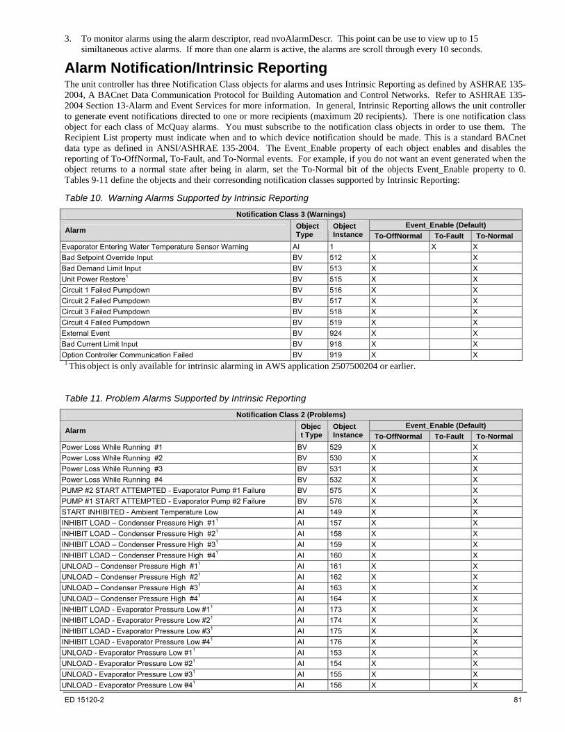
ED 15120-2 81
3. To monitor alarms using the alarm descriptor, read nvoAlarmDescr. This point can be use to view up to 15 similtaneous active alarms. If more than one alarm is active, the alarms are scroll through every 10 seconds.
Alarm Notification/Intrinsic Reporting The unit controller has three Notification Class objects for alarms and uses Intrinsic Reporting as defined by ASHRAE 135-2004, A BACnet Data Communication Protocol for Building Automation and Control Networks. Refer to ASHRAE 135-2004 Section 13-Alarm and Event Services for more information. In general, Intrinsic Reporting allows the unit controller to generate event notifications directed to one or more recipients (maximum 20 recipients). There is one notification class object for each class of McQuay alarms. You must subscribe to the notification class objects in order to use them. The Recipient List property must indicate when and to which device notification should be made. This is a standard BACnet data type as defined in ANSI/ASHRAE 135-2004. The Event_Enable property of each object enables and disables the reporting of To-OffNormal, To-Fault, and To-Normal events. For example, if you do not want an event generated when the object returns to a normal state after being in alarm, set the To-Normal bit of the objects Event_Enable property to 0. Tables 9-11 define the objects and their corresonding notification classes supported by Intrinsic Reporting:
Table 10. Warning Alarms Supported by Intrinsic Reporting
Notification Class 3 (Warnings)
Event_Enable (Default) Alarm
Object Type
Object Instance To-OffNormal To-Fault To-Normal
Evaporator Entering Water Temperature Sensor Warning AI 1 X X
Bad Setpoint Override Input BV 512 X X
Bad Demand Limit Input BV 513 X X
Unit Power Restore1 BV 515 X X
Circuit 1 Failed Pumpdown BV 516 X X
Circuit 2 Failed Pumpdown BV 517 X X
Circuit 3 Failed Pumpdown BV 518 X X
Circuit 4 Failed Pumpdown BV 519 X X
External Event BV 924 X X
Bad Current Limit Input BV 918 X X
Option Controller Communication Failed BV 919 X X 1 This object is only available for intrinsic alarming in AWS application 2507500204 or earlier.
Table 11. Problem Alarms Supported by Intrinsic Reporting
Notification Class 2 (Problems)
Event_Enable (Default) Alarm
Object Type
Object Instance To-OffNormal To-Fault To-Normal
Power Loss While Running #1 BV 529 X X
Power Loss While Running #2 BV 530 X X
Power Loss While Running #3 BV 531 X X
Power Loss While Running #4 BV 532 X X
PUMP #2 START ATTEMPTED - Evaporator Pump #1 Failure BV 575 X X
PUMP #1 START ATTEMPTED - Evaporator Pump #2 Failure BV 576 X X
START INHIBITED - Ambient Temperature Low AI 149 X X
INHIBIT LOAD – Condenser Pressure High #11 AI 157 X X
INHIBIT LOAD – Condenser Pressure High #21 AI 158 X X
INHIBIT LOAD – Condenser Pressure High #31 AI 159 X X
INHIBIT LOAD – Condenser Pressure High #41 AI 160 X X
UNLOAD – Condenser Pressure High #11 AI 161 X X
UNLOAD – Condenser Pressure High #21 AI 162 X X
UNLOAD – Condenser Pressure High #31 AI 163 X X
UNLOAD – Condenser Pressure High #41 AI 164 X X
INHIBIT LOAD - Evaporator Pressure Low #11 AI 173 X X
INHIBIT LOAD - Evaporator Pressure Low #21 AI 174 X X
INHIBIT LOAD - Evaporator Pressure Low #31 AI 175 X X
INHIBIT LOAD - Evaporator Pressure Low #41 AI 176 X X
UNLOAD - Evaporator Pressure Low #11 AI 153 X X
UNLOAD - Evaporator Pressure Low #21 AI 154 X X
UNLOAD - Evaporator Pressure Low #31 AI 155 X X
UNLOAD - Evaporator Pressure Low #41 AI 156 X X
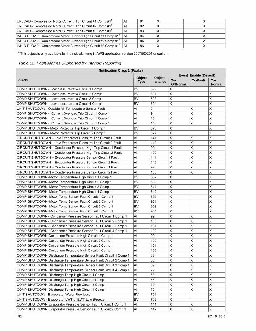
82 ED 15120-2
UNLOAD - Compressor Motor Current High Circuit #1 Comp #11 AI 181 X X
UNLOAD - Compressor Motor Current High Circuit #2 Comp #11 AI 182 X X
UNLOAD - Compressor Motor Current High Circuit #3 Comp #11 AI 183 X X
INHIBIT LOAD - Compressor Motor Current High Circuit #1 Comp #11 AI 184 X X
INHIBIT LOAD - Compressor Motor Current High Circuit #2 Comp #11 AI 185 X X
INHIBIT LOAD - Compressor Motor Current High Circuit #3 Comp #11 AI 186 X X
1 This object is only available for intrinsic alarming in AWS application version 2507500204 or earlier.
Table 12. Fault Alarms Supported by Intrinsic Reporting
Notification Class 1 (Faults)
Event_Enable (Default) Alarm
Object Type
Object Instance To-
OffNormal To-Fault To-
Normal
COMP SHUTDOWN - Low pressure ratio Circuit 1 Comp1 BV 599 X X
COMP SHUTDOWN - Low pressure ratio Circuit 2 Comp1 BV 601 X X
COMP SHUTDOWN - Low pressure ratio Circuit 3 Comp1 BV 603 X X
COMP SHUTDOWN - Low pressure ratio Circuit 4 Comp1 BV 604 X X
UNIT SHUTDOWN - Outside Air Temperature Sensor Fault AI 5 X X
COMP SHUTDOWN - Current Overload Trip Circuit 1 Comp 1 AI 9 X X X
COMP SHUTDOWN - Current Overload Trip Circuit 1 Comp 1 AI 12 X X X
COMP SHUTDOWN - Current Overload Trip Circuit 1 Comp 1 AI 15 X X X
COMP SHUTDOWN– Motor Protector Trip Circuit 1 Comp 1 BV 625 X X
COMP SHUTDOWN– Motor Protector Trip Circuit 2 Comp 1 BV 627 X X
CIRCUIT SHUTDOWN – Low Evaporator Pressure Trip Circuit 1 Fault AI 141 X X X
CIRCUIT SHUTDOWN – Low Evaporator Pressure Trip Circuit 2 Fault AI 142 X X X
CIRCUIT SHUTDOWN – Condenser Pressure High Trip Circuit 1 Fault AI 99 X X X
CIRCUIT SHUTDOWN – Condenser Pressure High Trip Circuit 2 Fault AI 100 X X X
CIRCUIT SHUTDOWN – Evaporator Pressure Sensor Circuit 1 Fault AI 141 X X X
CIRCUIT SHUTDOWN – Evaporator Pressure Sensor Circuit 2 Fault AI 142 X X X
CIRCUIT SHUTDOWN – Condensor Pressure Sensor Circuit 1 Fault AI 99 X X X
CIRCUIT SHUTDOWN – Condensor Pressure Sensor Circuit 2 Fault AI 100 X X X
COMP SHUTDOWN–Motor Temperature High Circuit 1 Comp 1 BV 637 X X
COMP SHUTDOWN–Motor Temperature High Circuit 2 Comp 1 BV 639 X X
COMP SHUTDOWN–Motor Temperature High Circuit 3 Comp 1 BV 641 X X
COMP SHUTDOWN–Motor Temperature High Circuit 4 Comp 1 BV 642 X X
COMP SHUTDOWN–Motor Temp Sensor Fault Circuit 1 Comp 1 BV 899 X X
COMP SHUTDOWN–Motor Temp Sensor Fault Circuit 2 Comp 1 BV 901 X X
COMP SHUTDOWN–Motor Temp Sensor Fault Circuit 3 Comp 1 BV 903 X X
COMP SHUTDOWN–Motor Temp Sensor Fault Circuit 4 Comp 1 BV 904 X X
COMP SHUTDOWN - Condenser Pressure Sensor Fault Circuit 1 Comp 1 AI 99 X X X
COMP SHUTDOWN - Condenser Pressure Sensor Fault Circuit 2 Comp 1 AI 100 X X X
COMP SHUTDOWN - Condenser Pressure Sensor Fault Circuit 3 Comp 1 AI 101 X X X
COMP SHUTDOWN - Condenser Pressure Sensor Fault Circuit 4 Comp 1 AI 102 X X X
COMP SHUTDOWN-Condenser Pressure High Circuit 1 Comp 1 AI 99 X X X
COMP SHUTDOWN-Condenser Pressure High Circuit 2 Comp 1 AI 100 X X X
COMP SHUTDOWN-Condenser Pressure High Circuit 3 Comp 1 AI 101 X X X
COMP SHUTDOWN-Condenser Pressure High Circuit 4 Comp 1 AI 102 X X X
COMP SHUTDOWN-Discharge Temperature Sensor Fault Circuit 1 Comp 1 AI 63 X X X
COMP SHUTDOWN-Discharge Temperature Sensor Fault Circuit 2 Comp 1 AI 66 X X X
COMP SHUTDOWN-Discharge Temperature Sensor Fault Circuit 3 Comp 1 AI 69 X X X
COMP SHUTDOWN-Discharge Temperature Sensor Fault Circuit 4 Comp 1 AI 72 X X X
COMP SHUTDOWN-Discharge Temp High Circuit 1 Comp 1 AI 63 X X X
COMP SHUTDOWN-Discharge Temp High Circuit 2 Comp 1 AI 66 X X X
COMP SHUTDOWN-Discharge Temp High Circuit 3 Comp 1 AI 69 X X X
COMP SHUTDOWN-Discharge Temp High Circuit 4 Comp 1 AI 72 X X X
UNIT SHUTDOWN - Evaporator Water Flow Loss BV 701 X X
UNIT SHUTDOWN - Evaporator LWT or EWT Low (Freeze) BV 702 X X
COMP SHUTDOWN-Evaporator Pressure Sensor Fault Circuit 1 Comp 1 AI 141 X X X
COMP SHUTDOWN-Evaporator Pressure Sensor Fault Circuit 2 Comp 1 AI 142 X X X
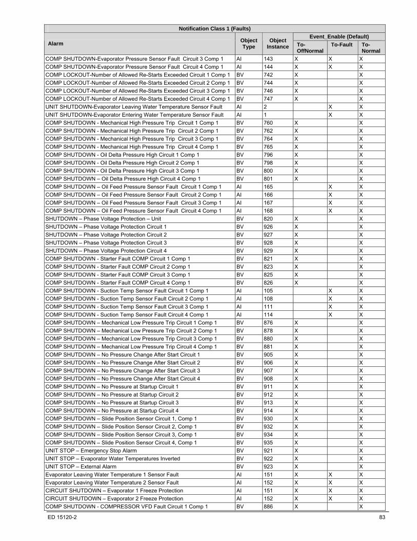
ED 15120-2 83
Notification Class 1 (Faults)
Event_Enable (Default) Alarm
Object Type
Object Instance To-
OffNormal To-Fault To-
Normal
COMP SHUTDOWN-Evaporator Pressure Sensor Fault Circuit 3 Comp 1 AI 143 X X X
COMP SHUTDOWN-Evaporator Pressure Sensor Fault Circuit 4 Comp 1 AI 144 X X X
COMP LOCKOUT-Number of Allowed Re-Starts Exceeded Circuit 1 Comp 1 BV 742 X X
COMP LOCKOUT-Number of Allowed Re-Starts Exceeded Circuit 2 Comp 1 BV 744 X X
COMP LOCKOUT-Number of Allowed Re-Starts Exceeded Circuit 3 Comp 1 BV 746 X X
COMP LOCKOUT-Number of Allowed Re-Starts Exceeded Circuit 4 Comp 1 BV 747 X X
UNIT SHUTDOWN-Evaporator Leaving Water Temperature Sensor Fault AI 2 X X
UNIT SHUTDOWN-Evaporator Entering Water Temperature Sensor Fault AI 1 X X
COMP SHUTDOWN - Mechanical High Pressure Trip Circuit 1 Comp 1 BV 760 X X
COMP SHUTDOWN - Mechanical High Pressure Trip Circuit 2 Comp 1 BV 762 X X
COMP SHUTDOWN - Mechanical High Pressure Trip Circuit 3 Comp 1 BV 764 X X
COMP SHUTDOWN - Mechanical High Pressure Trip Circuit 4 Comp 1 BV 765 X X
COMP SHUTDOWN - Oil Delta Pressure High Circuit 1 Comp 1 BV 796 X X
COMP SHUTDOWN - Oil Delta Pressure High Circuit 2 Comp 1 BV 798 X X
COMP SHUTDOWN - Oil Delta Pressure High Circuit 3 Comp 1 BV 800 X X
COMP SHUTDOWN – Oil Delta Pressure High Circuit 4 Comp 1 BV 801 X X
COMP SHUTDOWN – Oil Feed Pressure Sensor Fault Circuit 1 Comp 1 AI 165 X X
COMP SHUTDOWN – Oil Feed Pressure Sensor Fault Circuit 2 Comp 1 AI 166 X X
COMP SHUTDOWN – Oil Feed Pressure Sensor Fault Circuit 3 Comp 1 AI 167 X X
COMP SHUTDOWN – Oil Feed Pressure Sensor Fault Circuit 4 Comp 1 AI 168 X X
SHUTDOWN – Phase Voltage Protection – Unit BV 820 X X
SHUTDOWN – Phase Voltage Protection Circuit 1 BV 926 X X
SHUTDOWN – Phase Voltage Protection Circuit 2 BV 927 X X
SHUTDOWN – Phase Voltage Protection Circuit 3 BV 928 X X
SHUTDOWN – Phase Voltage Protection Circuit 4 BV 929 X X
COMP SHUTDOWN - Starter Fault COMP Circuit 1 Comp 1 BV 821 X X
COMP SHUTDOWN - Starter Fault COMP Circuit 2 Comp 1 BV 823 X X
COMP SHUTDOWN - Starter Fault COMP Circuit 3 Comp 1 BV 825 X X
COMP SHUTDOWN - Starter Fault COMP Circuit 4 Comp 1 BV 826 X X
COMP SHUTDOWN - Suction Temp Sensor Fault Circuit 1 Comp 1 AI 105 X X
COMP SHUTDOWN - Suction Temp Sensor Fault Circuit 2 Comp 1 AI 108 X X
COMP SHUTDOWN - Suction Temp Sensor Fault Circuit 3 Comp 1 AI 111 X X
COMP SHUTDOWN - Suction Temp Sensor Fault Circuit 4 Comp 1 AI 114 X X
COMP SHUTDOWN – Mechanical Low Pressure Trip Circuit 1 Comp 1 BV 876 X X
COMP SHUTDOWN – Mechanical Low Pressure Trip Circuit 2 Comp 1 BV 878 X X
COMP SHUTDOWN – Mechanical Low Pressure Trip Circuit 3 Comp 1 BV 880 X X
COMP SHUTDOWN – Mechanical Low Pressure Trip Circuit 4 Comp 1 BV 881 X X
COMP SHUTDOWN – No Pressure Change After Start Circuit 1 BV 905 X X
COMP SHUTDOWN – No Pressure Change After Start Circuit 2 BV 906 X X
COMP SHUTDOWN – No Pressure Change After Start Circuit 3 BV 907 X X
COMP SHUTDOWN – No Pressure Change After Start Circuit 4 BV 908 X X
COMP SHUTDOWN – No Pressure at Startup Circuit 1 BV 911 X X
COMP SHUTDOWN – No Pressure at Startup Circuit 2 BV 912 X X
COMP SHUTDOWN – No Pressure at Startup Circuit 3 BV 913 X X
COMP SHUTDOWN – No Pressure at Startup Circuit 4 BV 914 X X
COMP SHUTDOWN – Slide Position Sensor Circuit 1, Comp 1 BV 930 X X
COMP SHUTDOWN – Slide Position Sensor Circuit 2, Comp 1 BV 932 X X
COMP SHUTDOWN – Slide Position Sensor Circuit 3, Comp 1 BV 934 X X
COMP SHUTDOWN – Slide Position Sensor Circuit 4, Comp 1 BV 935 X X
UNIT STOP – Emergency Stop Alarm BV 921 X X
UNIT STOP – Evaporator Water Temperatures Inverted BV 922 X X
UNIT STOP – External Alarm BV 923 X X
Evaporator Leaving Water Temperature 1 Sensor Fault AI 151 X X X
Evaporator Leaving Water Temperature 2 Sensor Fault AI 152 X X X
CIRCUIT SHUTDOWN – Evaporator 1 Freeze Protection AI 151 X X X
CIRCUIT SHUTDOWN – Evaporator 2 Freeze Protection AI 152 X X X
COMP SHUTDOWN - COMPRESSOR VFD Fault Circuit 1 Comp 1 BV 886 X X
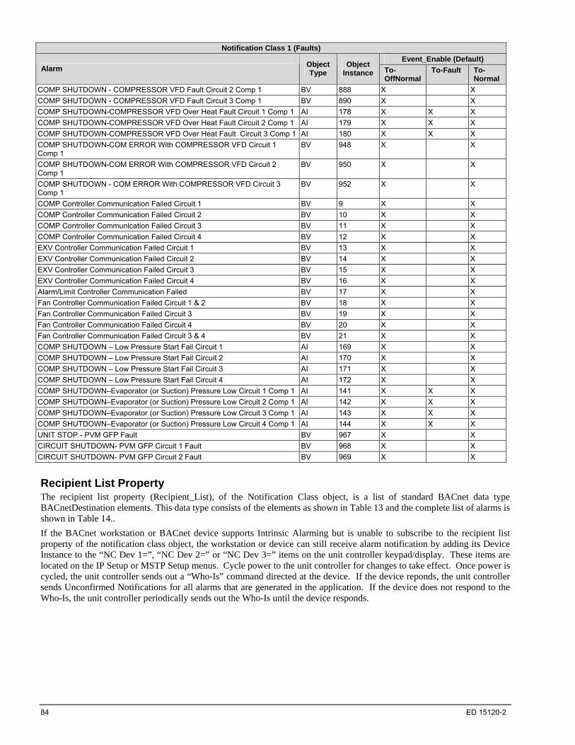
84 ED 15120-2
Notification Class 1 (Faults)
Event_Enable (Default) Alarm
Object Type
Object Instance To-
OffNormal To-Fault To-
Normal
COMP SHUTDOWN - COMPRESSOR VFD Fault Circuit 2 Comp 1 BV 888 X X
COMP SHUTDOWN - COMPRESSOR VFD Fault Circuit 3 Comp 1 BV 890 X X
COMP SHUTDOWN-COMPRESSOR VFD Over Heat Fault Circuit 1 Comp 1 AI 178 X X X
COMP SHUTDOWN-COMPRESSOR VFD Over Heat Fault Circuit 2 Comp 1 AI 179 X X X
COMP SHUTDOWN-COMPRESSOR VFD Over Heat Fault Circuit 3 Comp 1 AI 180 X X X
COMP SHUTDOWN-COM ERROR With COMPRESSOR VFD Circuit 1 Comp 1
BV 948 X X
COMP SHUTDOWN-COM ERROR With COMPRESSOR VFD Circuit 2 Comp 1
BV 950 X X
COMP SHUTDOWN - COM ERROR With COMPRESSOR VFD Circuit 3 Comp 1
BV 952 X X
COMP Controller Communication Failed Circuit 1 BV 9 X X
COMP Controller Communication Failed Circuit 2 BV 10 X X
COMP Controller Communication Failed Circuit 3 BV 11 X X
COMP Controller Communication Failed Circuit 4 BV 12 X X
EXV Controller Communication Failed Circuit 1 BV 13 X X
EXV Controller Communication Failed Circuit 2 BV 14 X X
EXV Controller Communication Failed Circuit 3 BV 15 X X
EXV Controller Communication Failed Circuit 4 BV 16 X X
Alarm/Limit Controller Communication Failed BV 17 X X
Fan Controller Communication Failed Circuit 1 & 2 BV 18 X X
Fan Controller Communication Failed Circuit 3 BV 19 X X
Fan Controller Communication Failed Circuit 4 BV 20 X X
Fan Controller Communication Failed Circuit 3 & 4 BV 21 X X
COMP SHUTDOWN – Low Pressure Start Fail Circuit 1 AI 169 X X
COMP SHUTDOWN – Low Pressure Start Fail Circuit 2 AI 170 X X
COMP SHUTDOWN – Low Pressure Start Fail Circuit 3 AI 171 X X
COMP SHUTDOWN – Low Pressure Start Fail Circuit 4 AI 172 X X
COMP SHUTDOWN–Evaporator (or Suction) Pressure Low Circuit 1 Comp 1 AI 141 X X X
COMP SHUTDOWN–Evaporator (or Suction) Pressure Low Circuit 2 Comp 1 AI 142 X X X
COMP SHUTDOWN–Evaporator (or Suction) Pressure Low Circuit 3 Comp 1 AI 143 X X X
COMP SHUTDOWN–Evaporator (or Suction) Pressure Low Circuit 4 Comp 1 AI 144 X X X
UNIT STOP - PVM GFP Fault BV 967 X X
CIRCUIT SHUTDOWN- PVM GFP Circuit 1 Fault BV 968 X X
CIRCUIT SHUTDOWN- PVM GFP Circuit 2 Fault BV 969 X X
Recipient List Property The recipient list property (Recipient_List), of the Notification Class object, is a list of standard BACnet data type BACnetDestination elements. This data type consists of the elements as shown in Table 13 and the complete list of alarms is shown in Table 14..
If the BACnet workstation or BACnet device supports Intrinsic Alarming but is unable to subscribe to the recipient list property of the notification class object, the workstation or device can still receive alarm notification by adding its Device Instance to the “NC Dev 1=”, “NC Dev 2=” or “NC Dev 3=” items on the unit controller keypad/display. These items are located on the IP Setup or MSTP Setup menus. Cycle power to the unit controller for changes to take effect. Once power is cycled, the unit controller sends out a “Who-Is” command directed at the device. If the device reponds, the unit controller sends Unconfirmed Notifications for all alarms that are generated in the application. If the device does not respond to the Who-Is, the unit controller periodically sends out the Who-Is until the device responds.
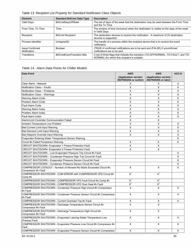
ED 15120-2 85
Table 13. Recipient List Property for Standard Notificaion Class Objects
Element Standard BACnet Data Type Description
Valid Days BACnetDaysOfWeek The set of days of the week that the destination may be used between the From Time and the To Time
From Time, To Time Time The window of time (inclusive) when the destination is visible on the days of the week in Valid Days
Recipient BACnet Recipient The destination devices to receive the notification. A maximum of 20 destination devices is supported.
Process Identifier Unsigned32 The handle of a process within the recipient device that is to receive the event notification
Issue Confirmed Notification
Boolean (TRUE) if confirmed notifications are to be sent and (FALSE) if unconfirmed notifications are to be sent
Transitions BACnetEventTransition Bits A set of three flags that indicate the transition (TO-OFFNORMAL, TO-FAULT, and TO-NORMAL) for which this recipient is suitable.
Table 14. Alarm Data Points for Chiller Models
Data Point AWS
(Application version 2507500204 or earlier)
AWS
(Application version 2507500205 or later)
AGZ-D
Clear Alarm - Network X X X
Notification Class – Faults X X X
Notification Class – Problems X X X
Notification Class – Warnings X X X
Warning Alarm Code X X X
Problem Alarm Code X X X
Fault Alarm Code X X X
Warning Alarm Index X X X
Problem Alarm Index X X X
Fault Alarm Index X X X
Alarm/Limit Controller Communication Failed X X
Ambient Temperature Low Problem X X X
Bad Current Limit Input Warning X X X
Bad Demand Limit Input Warning X X X
Bad Setpoint Override Input Warning X X X
Evaporator Entering Water Temperature Sensor Warning X
Circuit #n Failed Pumpdown Warning X X X
CIRCUIT SHUTDOWN- Evaporator 1 Freeze Protection Fault X X
CIRCUIT SHUTDOWN- Evaporator 2 Freeze Protection Fault X X
CIRCUIT SHUTDOWN – Low Evaporator Pressure Trip Circuit #n Fault X
CIRCUIT SHUTDOWN – Condenser Pressure High Trip Circuit #n Fault X
CIRCUIT SHUTDOWN – Evaporator Pressure Sensor Circuit #n Fault X
CIRCUIT SHUTDOWN – Condensor Pressure Sensor Circuit #n Fault X
COMPRESSOR LOCKOUT - Number of Allowed Re-Starts Exceeded Circuit #n Compressor #n Fault
X X X
COMPRESSOR SHUTDOWN - COM ERROR with COMPRESSOR VFD Circuit #n Comp #n
X1 X1
COMPRESSOR SHUTDOWN - COMPRESSOR VFD Fault Circuit #n Comp #n X1 X1
COMPRESSOR SHUTDOWN - COMPRESSOR VFD Over Heat #n Fault X1 X1
COMPRESSOR SHUTDOWN - Condenser Pressure High Circuit #n Compressor #n Fault
X X X
COMPRESSOR SHUTDOWN - Condenser Pressure Sensor Circuit #n Compressor #n Fault
X X X
COMPRESSOR SHUTDOWN - Current Overload Trip #n Fault X X X
COMPRESSOR SHUTDOWN - Discharge Temperature Sensor Circuit #n Compressor #n Fault
X X
COMPRESSOR SHUTDOWN - Discharge Temperature High Circuit #n Compressor #n Fault
X X
COMPRESSOR SHUTDOWN - Evaporator Leaving Water Temperature Low (Freeze) Fault
X X X
COMPRESSOR SHUTDOWN - Evaporator Pressure Low Circuit #n Compressor #n Fault
X X X
COMPRESSOR SHUTDOWN - Evaporator Pressure Sensor Circuit #n Compressor X X X
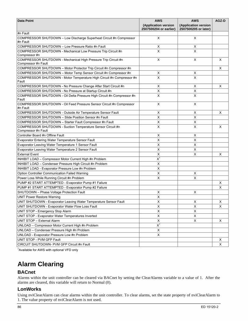
86 ED 15120-2
Data Point AWS
(Application version 2507500204 or earlier)
AWS
(Application version 2507500205 or later)
AGZ-D
#n Fault
COMPRESSOR SHUTDOWN – Low Discharge Superheat Circuit #n Compressor #n Fault
X X
COMPRESSOR SHUTDOWN – Low Pressure Ratio #n Fault X X
COMPRESSOR SHUTDOWN - Mechanical Low Pressure Trip Circuit #n Compressor #n
X X
COMPRESSOR SHUTDOWN - Mechanical High Pressure Trip Circuit #n Compressor #n Fault
X X X
COMPRESSOR SHUTDOWN – Motor Protector Trip Circuit #n Compressor #n X
COMPRESSOR SHUTDOWN – Motor Temp Sensor Circuit #n Compressor #n X X
COMPRESSOR SHUTDOWN - Motor Temperature High Circuit #n Compressor #n Fault
X X
COMPRESSOR SHUTDOWN - No Pressure Change After Start Circuit #n X X X
COMPRESSOR SHUTDOWN - No Pressure at Startup Circuit #n X X
COMPRESSOR SHUTDOWN - Oil Delta Pressure High Circuit #n Compressor #n Fault
X X
COMPRESSOR SHUTDOWN - Oil Feed Pressure Sensor Circuit #n Compressor #n Fault
X X
COMPRESSOR SHUTDOWN - Outside Air Temperature Sensor Fault X X X
COMPRESSOR SHUTDOWN – Slide Position Sensor #n Fault X X
COMPRESSOR SHUTDOWN – Starter Fault Compressor #n Fault X X
COMPRESSOR SHUTDOWN - Suction Temperature Sensor Circuit #n Compressor #n Fault
X X X
Controller Board #n Offline Fault X X
Evaporator Entering Water Temperature Sensor Fault X X
Evaporator Leaving Water Temperature 1 Sensor Fault X X
Evaporator Leaving Water Temperature 2 Sensor Fault X X
External Event X X X
INHIBIT LOAD – Compressor Motor Current High #n Problem X1
INHIBIT LOAD – Condenser Pressure High Circuit #n Problem X
INHIBIT LOAD - Evaporator Pressure Low #n Problem X
Option Controller Communication Failed Warning X X
Power Loss While Running Circuit #n Problem X X
PUMP #2 START ATTEMPTED - Evaporator Pump #1 Failure X
PUMP #1 START ATTEMPTED - Evaporator Pump #2 Failure X
SHUTDOWN – Phase Voltage Protection Fault X X
UNIT Power Restore Warning X
UNIT SHUTDOWN - Evaporator Leaving Water Temperature Sensor Fault X X X
UNIT SHUTDOWN - Evaporator Water Flow Loss Fault X X X
UNIT STOP - Emergency Stop Alarm X X
UNIT STOP - Evaporator Water Temperatures Inverted X X
UNIT STOP – External Alarm X X X
UNLOAD – Compressor Motor Current High #n Problem X1
UNLOAD – Condenser Pressure High #n Problem X
UNLOAD - Evaporator Pressure Low #n Problem X
UNIT STOP - PVM GFP Fault X
CIRCUIT SHUTDOWN- PVM GFP Circuit #n Fault X 1Available for AWS with optional VFD only
Alarm Clearing BACnet Alarms within the unit controller can be cleared via BACnet by setting the ClearAlarms variable to a value of 1. After the alarms are cleared, this variable will return to Normal (0).
LonWorks Using nviClearAlarm can clear alarms within the unit controller. To clear alarms, set the state property of nviClearAlarm to 1. The value property of nviClearAlarm is not used.

ED 15120-2 87
Clear Alarm - Network Keypad Menu Path No Keypad Equivalent This read/write input network variable clears all active alarms. Many alarms are automatically clearing alarms. Of the alarms that need to be manually cleared, only those listed below can be cleared from the network: UNIT SHUTDOWN - Evaporator Water Flow Loss
UNIT SHUTDOWN–Evaporator Leaving Water Temp Low (Freeze)
CIRCUIT SHUTDOWN – Evaporator 1 Freeze Protection
CIRCUIT SHUTDOWN – Evaporator 2 Freeze Protection
Measurement Units Data Type Usable Range Default Value
NA NA Integer Enumerated 0=Normal
BACnet Object Identifier Property Identifier
Object Type Type Enumeration Instance Property Name Property Enumeration
Binary Value 5 8 Present Value 85
Object Name
ClearAlarm
Property Values
0=Normal
1=Clear Alarms
LonWorks LONWORKS Name Profile SNVT Type SNVT Index SNVT Size
nviClearAlarm McQuay_Chiller switch 95 two bytes
Valid Range
State Value Clear Alarm
0 unused No Alarm
1 unused Clear Alarm
Notification Class - Faults Keypad Menu Path No Keypad Equivalent
These read/write properties allow subsciption to alarm notifications The Recipient_List conveys a list of one or more recipients to which notifications will be sent. The Ack_Required property defines whether or not acknowledgment is required for notifications generated due to To-OffNormal, To-Fault, and To-Normal event transitions. The Priority conveys the priority to be used for event notifications to To-OffNormal, To-Fault and To-Normal events. Refer to the Alarm Notification section for additional information, including a list of objects that report events to this notification class.
Measurement Units Data Type Valid Range Default Value
Notification N/A List of BACnetDestination N/A N/A
BACnet Object Identifier Property
Object Type Type ID Instance Name ID
Notification Class 15 1 recipient_list 102
Object Name
NC1-Faults1, 2 1 If the BACnet Workstation is unable to subscribe to the recipient_list, you can still subscribe to alarms using the unit controller keypad/display. Navigate
to the IP Setup or MSTP Setup menu and enter the Device Instance of the device to receive the alarms in the “NC Dev 1=”, “NC Dev 2=” or “NC Dev 3=” entries. You must cycle power to the unit controller after changing these properties via the keypad/display.
2 Maximum of 20 recipients at one time.

88 ED 15120-2
Object Identifier Property
Object Type Type ID Instance Name ID
Notification Class 15 1 Ack_Required 1
Object Name
NC1-Faults
Object Identifier Property
Object Type Type ID Instance Name ID
Notification Class 15 1 Priority 86 Object Name
NC1-Faults1 1 A lower number indicates a higher priority.
LonWorks No LONWORKS equivalent
Notification Class - Problems Keypad Menu Path No Keypad Equivalent
These read/write properties allow subsciption to alarm notifications. The Recipient_List conveys a list of one or more recipients to which notifications will be sent. The Ack_Required property defines whether or not acknowledgment is required for notifications generated due to To-OffNormal, To-Fault, and To-Normal event transitions. The Priority conveys the priority to be used for event notifications to To-OffNormal, To-Fault and To-Normal events. Refer to the Alarm Notification section for additional information, including a list of objects that report events to this notification class.
Measurement Units Data Type Valid Range Default Value
Notification N/A List of BACnetDestination N/A N/A
BACnet Object Identifier Property
Object Type Type ID Instance Name ID
Notification Class 15 2 recipient_list 102
Object Name
NC1-Problems1, 2 1 If the BACnet Workstation is unable to subscribe to the recipient_list, you can still subscribe to alarms on the unit controller keypad/display Navigate to
the IP Setup or MSTP Setup menu and enter the Device Instance of the device to receive the alarms in the “NC Dev 1=”, “NC Dev 2=” or “NC Dev 3=” entries. You must cycle power to the unit controller after changing these properties via the unit controller keypad/display.
2 Maximum of 20 recipients at one time.
Object Identifier Property
Object Type Type ID Instance Name ID
Notification Class 15 2 Ack_Required 1
Object Name
NC1-Problems
Object Identifier Property
Object Type Type ID Instance Name ID
Notification Class 15 2 Priority 86
Object Name
NC1-Problems1 1 A lower number indicates a higher priority.
LonWorks No LONWORKS equivalent.

ED 15120-2 89
Notification Class - Warnings Keypad Menu Path No Keypad Equivalent
These read/write properties allow subsciption to alarm notifications. The Recipient_List conveys a list of one or more recipients to which notifications will be sent. The Ack_Required property defines whether or not acknowledgment is required for notifications generated due to To-OffNormal, To-Fault, and To-Normal event transitions. The Priority conveys the priority to be used for event notifications to To-OffNormal, To-Fault and To-Normal events. Refer to the Alarm Notification section for additional information, including a list of objects that report events to this notification class.
Measurement Units Data Type Valid Range Default Value
Notification N/A List of BACnetDestination N/A N/A
BACnet Object Identifier Property
Object Type Type ID Instance Name ID
Notification Class 15 3 recipient_list 102
Object Name
NC1-Warnings1, 2 1 If the BACnet Workstation is unable to subscribe to the recipient_list, you can still subscribe to alarms on the unit controller keypad display. Navigate to
the IP Setup or MSTP Setup menu and enter the Device Instance of the device to receive the alarms in the “NC Dev 1=”, “NC Dev 2=” or “NC Dev 3=” entries. You must cycle power to the unit controller after changing these properties via the keypad/display.
2 Maximum of 20 recipients at one time.
Object Identifier Property
Object Type Type ID Instance Name ID
Notification Class 15 3 Ack_Required 1
Object Name
NC1-Warnings
Object Identifier Property
Object Type Type ID Instance Name ID
Notification Class 15 3 Priority 86
Object Name
NC1-Warnings1 1 A lower number indicates a higher priority.
LonWorks No LONWORKS equivalent.
Warning Alarm Code Keypad Menu Path No Keypad Equivalent This object allows individual notification of the active warning alarm. The alarms are not ordered based on any priority. If multipe warning alarms are present at one time, this object will be set to the alarm that has the highest alarm code. This object is set to zero if no warning alarms are active.
Measurement Units Data Type Valid Range Default Value
Alarms N/A BACnet: Real LONWORKS: Floating Point
Enumerated N/A
BACnet Object Identifier Property
Object Type Type ID Instance Name ID
Analog Value 2 903 Present_Value 85
Object Name
AVWarningAlarmCode
Property Value
Refer to the Protocol Point Summary – BACnet table on page 16 for possible values.
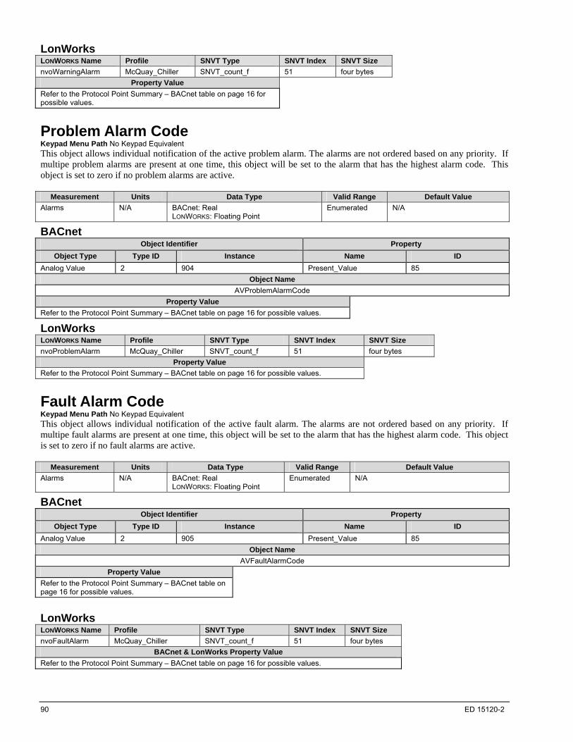
90 ED 15120-2
LonWorks LONWORKS Name Profile SNVT Type SNVT Index SNVT Size
nvoWarningAlarm McQuay_Chiller SNVT_count_f 51 four bytes
Property Value
Refer to the Protocol Point Summary – BACnet table on page 16 for possible values.
Problem Alarm Code Keypad Menu Path No Keypad Equivalent This object allows individual notification of the active problem alarm. The alarms are not ordered based on any priority. If multipe problem alarms are present at one time, this object will be set to the alarm that has the highest alarm code. This object is set to zero if no problem alarms are active.
Measurement Units Data Type Valid Range Default Value
Alarms N/A BACnet: Real LONWORKS: Floating Point
Enumerated N/A
BACnet Object Identifier Property
Object Type Type ID Instance Name ID
Analog Value 2 904 Present_Value 85
Object Name
AVProblemAlarmCode
Property Value
Refer to the Protocol Point Summary – BACnet table on page 16 for possible values.
LonWorks LONWORKS Name Profile SNVT Type SNVT Index SNVT Size
nvoProblemAlarm McQuay_Chiller SNVT_count_f 51 four bytes
Property Value
Refer to the Protocol Point Summary – BACnet table on page 16 for possible values.
Fault Alarm Code Keypad Menu Path No Keypad Equivalent This object allows individual notification of the active fault alarm. The alarms are not ordered based on any priority. If multipe fault alarms are present at one time, this object will be set to the alarm that has the highest alarm code. This object is set to zero if no fault alarms are active.
Measurement Units Data Type Valid Range Default Value
Alarms N/A BACnet: Real LONWORKS: Floating Point
Enumerated N/A
BACnet Object Identifier Property
Object Type Type ID Instance Name ID
Analog Value 2 905 Present_Value 85
Object Name
AVFaultAlarmCode
Property Value
Refer to the Protocol Point Summary – BACnet table on page 16 for possible values.
LonWorks LONWORKS Name Profile SNVT Type SNVT Index SNVT Size
nvoFaultAlarm McQuay_Chiller SNVT_count_f 51 four bytes
BACnet & LonWorks Property Value
Refer to the Protocol Point Summary – BACnet table on page 16 for possible values.

ED 15120-2 91
Warning Alarm Index Keypad Menu Path No Keypad Equivalent This object allows individual notification of the active warning alarm. The alarms are not ordered based on any priority. If multipe warning alarms are present at one time, this object will be set to the alarm that has the highest alarm index. This object is set to zero if no warning alarms are active.
Measurement Units Data Type Valid Range Default Value
Alarms N/A BACnet: Real LONWORKS: Floating Point
Enumerated N/A
BACnet Object Identifier Property
Object Type Type ID Instance Name ID
Analog Value 2 902 Present_Value 85
Object Name
AVWarningAlarm
Property Value
Refer to the Protocol Point Summary – BACnet table on page 16 for possible values.
LonWorks No LONWORKS equivalent.
Problem Alarm Index Keypad Menu Path No Keypad Equivalent This object allows individual notification of the active problem alarm. The alarms are not ordered based on any priority. If multipe problem alarms are present at one time, this object will be set to the alarm that has the highest alarm index. This object is set to zero if no problem alarms are active.
Measurement Units Data Type Valid Range Default Value
Alarms N/A BACnet: Real LONWORKS: Floating Point
Enumerated N/A
BACnet Object Identifier Property
Object Type Type ID Instance Name ID
Analog Value 2 900 Present_Value 85
Object Name
AVProblemAlarm
Property Value
Refer to the Protocol Point Summary – BACnet table on page 16 for possible values.
LonWorks No LONWORKS equivalent.
Fault Alarm Index Keypad Menu Path No Keypad Equivalent This object allows individual notification of the active fault alarm. The alarms are not ordered based on any priority. If multipe fault alarms are present at one time, this object will be set to the alarm that has the highest alarm index. This object is set to zero if no fault alarms are active.
Measurement Units Data Type Valid Range Default Value
Alarms N/A BACnet: Real Enumerated N/A

92 ED 15120-2
BACnet Object Identifier Property
Object Type Type ID Instance Name ID
Analog Value 2 901 Present_Value 85
Object Name
AVFaultAlarm
Property Value
Refer to the Protocol Point Summary – BACnet table on page 16 for possible values.
LonWorks No LONWORKS equivalent.
Alarm/Limit Controller Communication Failed Keypad Menu Path No Keypad Equivalent
This commandable BACnet object is setup to generate Alarm/Limit Controller Communication Failed alarm. The purpose of this object is for Intrinsic Alarming, and although it is commandable, writing to it will interfere with this function.
Measurement Units Data Type Usable Range Default Value
NA NA Binary Enumerated N/A
BACnet Object Identifier Property Identifier
Object Type Type Enumeration Instance Property Name Property Enumeration
Binary Value 5 17 Present Value 85
Object Name
AlarmLimitCtrlrCommFail
Property Values
0=NoAlarm
1=InAlarm
Ambient Temperature Low Problem Keypad Menu Path No Keypad Equivalent
This commandable BACnet object indicates whether the START INHIBITED - Ambient Temperature Low Problem is active (1) or not (0).
Measurement Units Data Type Valid Range Default Value
Alarm N/A Enumerated 0-1 N/A
BACnet Object Identifier Property
Object Type Type ID Instance Name ID
Binary Value 5 533 Present_Value 85
Object Name
StartInhbtAmbTempLow
Enumeration
0=NoAlarm
1=InAlarm
LonWorks No LONWORKS equivalent.
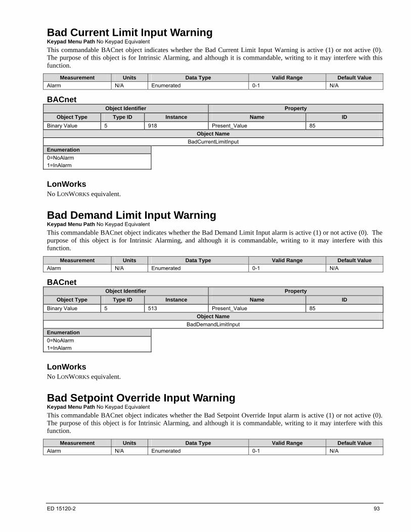
ED 15120-2 93
Bad Current Limit Input Warning Keypad Menu Path No Keypad Equivalent
This commandable BACnet object indicates whether the Bad Current Limit Input Warning is active (1) or not active (0). The purpose of this object is for Intrinsic Alarming, and although it is commandable, writing to it may interfere with this function.
Measurement Units Data Type Valid Range Default Value
Alarm N/A Enumerated 0-1 N/A
BACnet Object Identifier Property
Object Type Type ID Instance Name ID
Binary Value 5 918 Present_Value 85
Object Name
BadCurrentLimitInput
Enumeration
0=NoAlarm
1=InAlarm
LonWorks No LONWORKS equivalent.
Bad Demand Limit Input Warning Keypad Menu Path No Keypad Equivalent
This commandable BACnet object indicates whether the Bad Demand Limit Input alarm is active (1) or not active (0). The purpose of this object is for Intrinsic Alarming, and although it is commandable, writing to it may interfere with this function.
Measurement Units Data Type Valid Range Default Value
Alarm N/A Enumerated 0-1 N/A
BACnet Object Identifier Property
Object Type Type ID Instance Name ID
Binary Value 5 513 Present_Value 85
Object Name
BadDemandLimitInput
Enumeration
0=NoAlarm
1=InAlarm
LonWorks No LONWORKS equivalent.
Bad Setpoint Override Input Warning Keypad Menu Path No Keypad Equivalent
This commandable BACnet object indicates whether the Bad Setpoint Override Input alarm is active (1) or not active (0). The purpose of this object is for Intrinsic Alarming, and although it is commandable, writing to it may interfere with this function.
Measurement Units Data Type Valid Range Default Value
Alarm N/A Enumerated 0-1 N/A
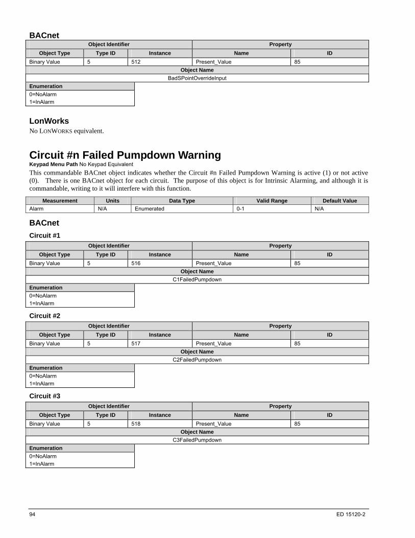
94 ED 15120-2
BACnet Object Identifier Property
Object Type Type ID Instance Name ID
Binary Value 5 512 Present_Value 85
Object Name
BadSPointOverrideInput
Enumeration
0=NoAlarm
1=InAlarm
LonWorks No LONWORKS equivalent.
Circuit #n Failed Pumpdown Warning Keypad Menu Path No Keypad Equivalent
This commandable BACnet object indicates whether the Circuit #n Failed Pumpdown Warning is active (1) or not active (0). There is one BACnet object for each circuit. The purpose of this object is for Intrinsic Alarming, and although it is commandable, writing to it will interfere with this function.
Measurement Units Data Type Valid Range Default Value
Alarm N/A Enumerated 0-1 N/A
BACnet
Circuit #1
Object Identifier Property
Object Type Type ID Instance Name ID
Binary Value 5 516 Present_Value 85
Object Name
C1FailedPumpdown
Enumeration
0=NoAlarm
1=InAlarm
Circuit #2
Object Identifier Property
Object Type Type ID Instance Name ID
Binary Value 5 517 Present_Value 85
Object Name
C2FailedPumpdown
Enumeration
0=NoAlarm
1=InAlarm
Circuit #3
Object Identifier Property
Object Type Type ID Instance Name ID
Binary Value 5 518 Present_Value 85
Object Name
C3FailedPumpdown
Enumeration
0=NoAlarm
1=InAlarm
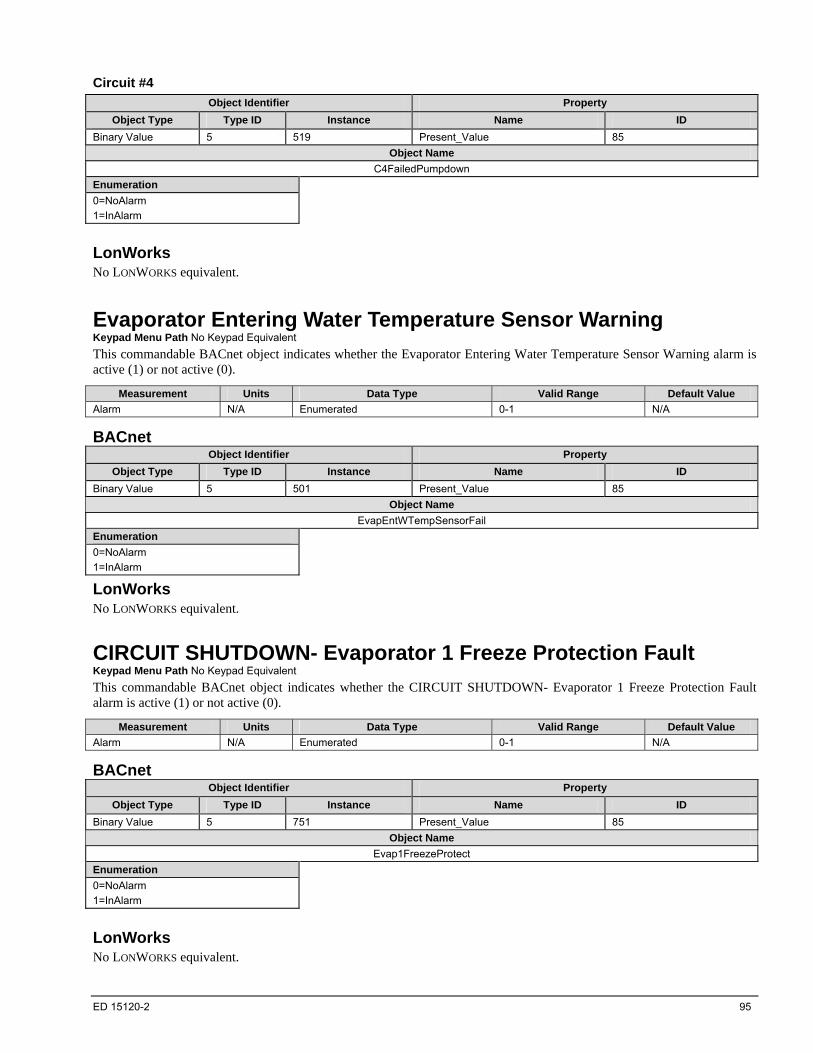
ED 15120-2 95
Circuit #4
Object Identifier Property
Object Type Type ID Instance Name ID
Binary Value 5 519 Present_Value 85
Object Name
C4FailedPumpdown
Enumeration
0=NoAlarm
1=InAlarm
LonWorks No LONWORKS equivalent.
Evaporator Entering Water Temperature Sensor Warning Keypad Menu Path No Keypad Equivalent
This commandable BACnet object indicates whether the Evaporator Entering Water Temperature Sensor Warning alarm is active (1) or not active (0).
Measurement Units Data Type Valid Range Default Value
Alarm N/A Enumerated 0-1 N/A
BACnet Object Identifier Property
Object Type Type ID Instance Name ID
Binary Value 5 501 Present_Value 85
Object Name
EvapEntWTempSensorFail
Enumeration
0=NoAlarm
1=InAlarm
LonWorks No LONWORKS equivalent.
CIRCUIT SHUTDOWN- Evaporator 1 Freeze Protection Fault Keypad Menu Path No Keypad Equivalent
This commandable BACnet object indicates whether the CIRCUIT SHUTDOWN- Evaporator 1 Freeze Protection Fault alarm is active (1) or not active (0).
Measurement Units Data Type Valid Range Default Value
Alarm N/A Enumerated 0-1 N/A
BACnet Object Identifier Property
Object Type Type ID Instance Name ID
Binary Value 5 751 Present_Value 85
Object Name
Evap1FreezeProtect
Enumeration
0=NoAlarm
1=InAlarm
LonWorks No LONWORKS equivalent.
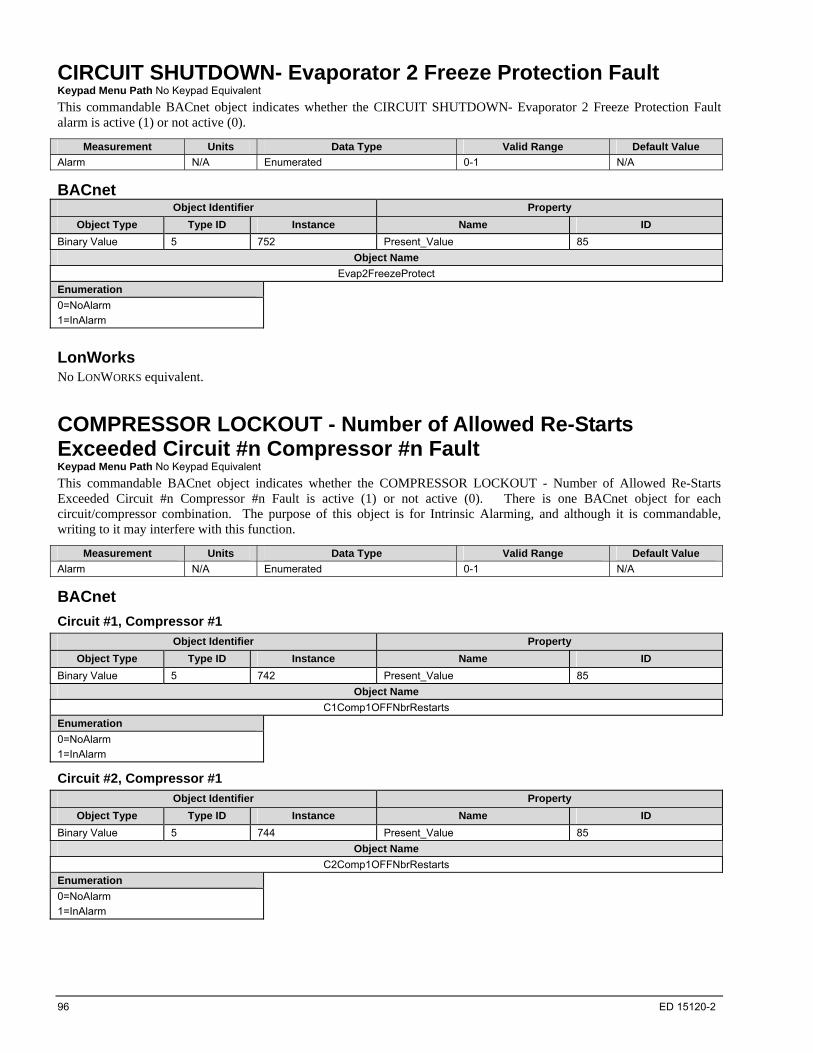
96 ED 15120-2
CIRCUIT SHUTDOWN- Evaporator 2 Freeze Protection Fault Keypad Menu Path No Keypad Equivalent
This commandable BACnet object indicates whether the CIRCUIT SHUTDOWN- Evaporator 2 Freeze Protection Fault alarm is active (1) or not active (0).
Measurement Units Data Type Valid Range Default Value
Alarm N/A Enumerated 0-1 N/A
BACnet Object Identifier Property
Object Type Type ID Instance Name ID
Binary Value 5 752 Present_Value 85
Object Name
Evap2FreezeProtect
Enumeration
0=NoAlarm
1=InAlarm
LonWorks No LONWORKS equivalent.
COMPRESSOR LOCKOUT - Number of Allowed Re-Starts Exceeded Circuit #n Compressor #n Fault Keypad Menu Path No Keypad Equivalent
This commandable BACnet object indicates whether the COMPRESSOR LOCKOUT - Number of Allowed Re-Starts Exceeded Circuit #n Compressor #n Fault is active (1) or not active (0). There is one BACnet object for each circuit/compressor combination. The purpose of this object is for Intrinsic Alarming, and although it is commandable, writing to it may interfere with this function.
Measurement Units Data Type Valid Range Default Value
Alarm N/A Enumerated 0-1 N/A
BACnet
Circuit #1, Compressor #1
Object Identifier Property
Object Type Type ID Instance Name ID
Binary Value 5 742 Present_Value 85
Object Name
C1Comp1OFFNbrRestarts
Enumeration
0=NoAlarm
1=InAlarm
Circuit #2, Compressor #1
Object Identifier Property
Object Type Type ID Instance Name ID
Binary Value 5 744 Present_Value 85
Object Name
C2Comp1OFFNbrRestarts
Enumeration
0=NoAlarm
1=InAlarm

ED 15120-2 97
Circuit #3, Compressor #1
Object Identifier Property
Object Type Type ID Instance Name ID
Binary Value 5 746 Present_Value 85
Object Name
C3Comp1OFFNbrRestarts
Enumeration
0=NoAlarm
1=InAlarm
Circuit #4, Compressor #1
Object Identifier Property
Object Type Type ID Instance Name ID
Binary Value 5 747 Present_Value 85
Object Name
C4Comp1OFFNbrRestarts
Enumeration
0=NoAlarm
1=InAlarm
LonWorks No LONWORKS equivalent.
COMPRESSOR SHUTDOWN - COM ERROR with COMPRESSOR VFD Circuit #n Comp #n Keypad Menu Path No Keypad Equivalent
This commandable BACnet object indicates whether the COMPRESSOR SHUTDOWN - COM ERROR With COMPRESSOR VFD Circuit #n Comp #n Fault is active (1) or not active (0). There is one BACnet object for each circuit/compressor combination.
Measurement Units Data Type Valid Range Default Value
Alarm N/A Enumerated 0-1 N/A
BACnet
Circuit #1, Compressor #1
Object Identifier Property
Object Type Type ID Instance Name ID
Binary Value 5 948 Present_Value 85
Object Name
C1Cmp1OffVfdCommFail
Enumeration
0=NoAlarm
1=InAlarm
Circuit #2, Compressor #1
Object Identifier Property
Object Type Type ID Instance Name ID
Binary Value 5 950 Present_Value 85
Object Name
C2Cmp1OffVfdCommFail
Enumeration
0=NoAlarm
1=InAlarm

98 ED 15120-2
Circuit #3, Compressor #1
Object Identifier Property
Object Type Type ID Instance Name ID
Binary Value 5 952 Present_Value 85
Object Name
C3Cmp1OffVfdCommFail
Enumeration
0=NoAlarm
1=InAlarm
LonWorks No LONWORKS equivalent.
COMPRESSOR SHUTDOWN - COMPRESSOR VFD Fault Circuit #n Comp #n Keypad Menu Path No Keypad Equivalent
This commandable BACnet object indicates whether the COMPRESSOR SHUTDOWN - COMPRESSOR VFD Fault Circuit #n Comp #n Fault is active (1) or not active (0). There is one BACnet object for each circuit/compressor combination.
Measurement Units Data Type Valid Range Default Value
Alarm N/A Enumerated 0-1 N/A
BACnet
Circuit #1, Compressor #1
Object Identifier Property
Object Type Type ID Instance Name ID
Binary Value 5 886 Present_Value 85
Object Name
C1Cmp1OffVfdFault
Enumeration
0=NoAlarm
1=InAlarm
Circuit #2, Compressor #1
Object Identifier Property
Object Type Type ID Instance Name ID
Binary Value 5 888 Present_Value 85
Object Name
C2Cmp1OffVfdFault
Enumeration
0=NoAlarm
1=InAlarm
Circuit #3, Compressor #1
Object Identifier Property
Object Type Type ID Instance Name ID
Binary Value 5 890 Present_Value 85
Object Name
C3Cmp1OffVfdFault
Enumeration
0=NoAlarm
1=InAlarm
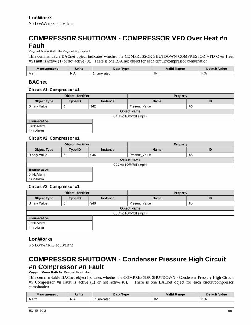
ED 15120-2 99
LonWorks No LONWORKS equivalent.
COMPRESSOR SHUTDOWN - COMPRESSOR VFD Over Heat #n Fault Keypad Menu Path No Keypad Equivalent
This commandable BACnet object indicates whether the COMPRESSOR SHUTDOWN COMPRESSOR VFD Over Heat #n Fault is active (1) or not active (0). There is one BACnet object for each circuit/compressor combination.
Measurement Units Data Type Valid Range Default Value
Alarm N/A Enumerated 0-1 N/A
BACnet
Circuit #1, Compressor #1
Object Identifier Property
Object Type Type ID Instance Name ID
Binary Value 5 942 Present_Value 85
Object Name
C1Cmp1OffVfdTempHi
Enumeration
0=NoAlarm
1=InAlarm
Circuit #2, Compressor #1
Object Identifier Property
Object Type Type ID Instance Name ID
Binary Value 5 944 Present_Value 85
Object Name
C2Cmp1OffVfdTempHi
Enumeration
0=NoAlarm
1=InAlarm
Circuit #3, Compressor #1
Object Identifier Property
Object Type Type ID Instance Name ID
Binary Value 5 946 Present_Value 85
Object Name
C3Cmp1OffVfdTempHi
Enumeration
0=NoAlarm
1=InAlarm
LonWorks No LONWORKS equivalent.
COMPRESSOR SHUTDOWN - Condenser Pressure High Circuit #n Compressor #n Fault Keypad Menu Path No Keypad Equivalent
This commandable BACnet object indicates whether the COMPRESSOR SHUTDOWN - Condenser Pressure High Circuit #n Compressor #n Fault is active (1) or not active (0). There is one BACnet object for each circuit/compressor combination.
Measurement Units Data Type Valid Range Default Value
Alarm N/A Enumerated 0-1 N/A

100 ED 15120-2
BACnet
Circuit #1, Compressor #1
Object Identifier Property
Object Type Type ID Instance Name ID
Binary Value 5 676 Present_Value 85
Object Name
C1Comp1OFFCondPressHi
Enumeration
0=NoAlarm
1=InAlarm
Circuit #2, Compressor #1
Object Identifier Property
Object Type Type ID Instance Name ID
Binary Value 5 678 Present_Value 85
Object Name
C2Comp1OFFCondPressHi
Enumeration
0=NoAlarm
1=InAlarm
Circuit #3, Compressor #1
Object Identifier Property
Object Type Type ID Instance Name ID
Binary Value 5 680 Present_Value 85
Object Name
C3Comp1OFFCondPressHi
Enumeration
0=NoAlarm
1=InAlarm
Circuit #4, Compressor #1
Object Identifier Property
Object Type Type ID Instance Name ID
Binary Value 5 681 Present_Value 85
Object Name
C4Comp1OFFCondPressHi
Enumeration
0=NoAlarm
1=InAlarm
LonWorks No LONWORKS equivalent.
COMPRESSOR SHUTDOWN - Condenser Pressure Sensor Circuit #n Compressor #n Fault Keypad Menu Path No Keypad Equivalent
This commandable BACnet object indicates whether the COMPRESSOR SHUTDOWN - Condenser Pressure Sensor Circuit #n Compressor #n Fault is active (1) or not active (0). There is one BACnet object for each circuit/compressor combination.
Measurement Units Data Type Valid Range Default Value
Alarm N/A Enumerated 0-1 N/A

ED 15120-2 101
BACnet
Circuit #1, Compressor #1
Object Identifier Property
Object Type Type ID Instance Name ID
Binary Value 5 668 Present_Value 85
Object Name
C1Comp1OFFCondPressSen
Enumeration
0=NoAlarm
1=InAlarm
Circuit #2, Compressor #1
Object Identifier Property
Object Type Type ID Instance Name ID
Binary Value 5 670 Present_Value 85
Object Name
C2Comp1OFFCondPressSen
Enumeration
0=NoAlarm
1=InAlarm
Circuit #3, Compressor #1
Object Identifier Property
Object Type Type ID Instance Name ID
Binary Value 5 672 Present_Value 85
Object Name
C3Comp1OFFCondPressSen
Enumeration
0=NoAlarm
1=InAlarm
Circuit #4, Compressor #1
Object Identifier Property
Object Type Type ID Instance Name ID
Binary Value 5 673 Present_Value 85
Object Name
C4Comp1OFFCondPressSen
Enumeration
0=NoAlarm
1=InAlarm
LonWorks No LONWORKS equivalent.
COMPRESSOR SHUTDOWN - Current Overload Trip #n Fault Keypad Menu Path No Keypad Equivalent
This commandable BACnet object indicates whether the COMPRESSOR SHUTDOWN - Current Overload Trip #n Fault is active (1) or not active (0). There is one BACnet object for each circuit/compressor combination.
Measurement Units Data Type Valid Range Default Value
Alarm N/A Enumerated 0-1 N/A

102 ED 15120-2
BACnet
Circuit #1, Compressor #1
Object Identifier Property
Object Type Type ID Instance Name ID
Binary Value 5 606 Present_Value 85
Object Name
C1Cmp1OffCurrentHi
Enumeration
0=NoAlarm
1=InAlarm
Circuit #2, Compressor #1
Object Identifier Property
Object Type Type ID Instance Name ID
Binary Value 5 608 Present_Value 85
Object Name
C2Cmp1OffCurrentHi
Enumeration
0=NoAlarm
1=InAlarm
Circuit #3, Compressor #1
Object Identifier Property
Object Type Type ID Instance Name ID
Binary Value 5 610 Present_Value 85
Object Name
C3Cmp1OffCurrentHi
Enumeration
0=NoAlarm
1=InAlarm
LonWorks No LONWORKS equivalent.
COMPRESSOR SHUTDOWN - Discharge Temperature Sensor Circuit #n Compressor #n Fault Keypad Menu Path No Keypad Equivalent
This commandable BACnet object indicates whether the COMPRESSOR SHUTDOWN - Discharge Temperature Sensor Circuit #n Compressor #n Fault is active (1) or not active (0). There is one BACnet object for each cicruit/compressor combination.
Measurement Units Data Type Valid Range Default Value
Alarm N/A Enumerated 0-1 N/A
BACnet
Circuit #1, Compressor #1
Object Identifier Property
Object Type Type ID Instance Name ID
Binary Value 5 688 Present_Value 85
Object Name
C1Comp1OFFDischTempSen
Enumeration
0=NoAlarm
1=InAlarm

ED 15120-2 103
Circuit #2, Compressor #1
Object Identifier Property
Object Type Type ID Instance Name ID
Binary Value 5 690 Present_Value 85
Object Name
C2Comp1OFFDischTempSen
Enumeration
0=NoAlarm
1=InAlarm
Circuit #3, Compressor #1
Object Identifier Property
Object Type Type ID Instance Name ID
Binary Value 5 692 Present_Value 85
Object Name
C3Comp1OFFDischTempSen
Enumeration
0=NoAlarm
1=InAlarm
Circuit #4, Compressor #1
Object Identifier Property
Object Type Type ID Instance Name ID
Binary Value 5 693 Present_Value 85
Object Name
C4Comp1OFFDischTempSen
Enumeration
0=NoAlarm
1=InAlarm
LonWorks No LONWORKS equivalent.
COMPRESSOR SHUTDOWN - Discharge Temperature High Circuit #n Compressor #n Fault Keypad Menu Path No Keypad Equivalent
This commandable BACnet object indicates whether the COMPRESSOR SHUTDOWN - Discharge Temperature High Circuit #n Compressor #n Fault is active (1) or not active (0). There is one BACnet object for each combination of circuits and compressors.
Measurement Units Data Type Valid Range Default Value
Alarm N/A Enumerated 0-1 N/A
BACnet
Circuit #1, Compressor #1
Object Identifier Property
Object Type Type ID Instance Name ID
Binary Value 5 694 Present_Value 85
Object Name
C1Comp1OFFDischTempHi
Enumeration
0=NoAlarm
1=InAlarm

104 ED 15120-2
Circuit #2, Compressor #1
Object Identifier Property
Object Type Type ID Instance Name ID
Binary Value 5 696 Present_Value 85
Object Name
C2Comp1OFFDischTempHi
Enumeration
0=NoAlarm
1=InAlarm
Circuit #3, Compressor #1
Object Identifier Property
Object Type Type ID Instance Name ID
Binary Value 5 698 Present_Value 85
Object Name
C3Comp1OFFDischTempHi
Enumeration
0=NoAlarm
1=InAlarm
Circuit #4, Compressor #1
Object Identifier Property
Object Type Type ID Instance Name ID
Binary Value 5 699 Present_Value 85
Object Name
C4Comp1OFFDischTempHi
Enumeration
0=NoAlarm
1=InAlarm
LonWorks No LONWORKS equivalent.
COMPRESSOR SHUTDOWN - Evaporator Leaving Water Temperature Low (Freeze) Fault Keypad Menu Path No Keypad Equivalent
This commandable BACnet object indicates whether the COMPRESSOR SHUTDOWN - Evaporator Leaving Water Temperature Low (Freeze) Fault is active (1) or not active (0). The purpose of this object is for Intrinsic Alarming, and although it is commandable, writing to it may interfere with this function.
Measurement Units Data Type Valid Range Default Value
Alarm N/A Enumerated 0-1 N/A
BACnet Object Identifier Property
Object Type Type ID Instance Name ID
Binary Value 5 702 Present_Value 85
Object Name
UnitOFFEvapLvgWTempLo
Enumeration
0=NoAlarm
1=InAlarm
LonWorks No LONWORKS equivalent.
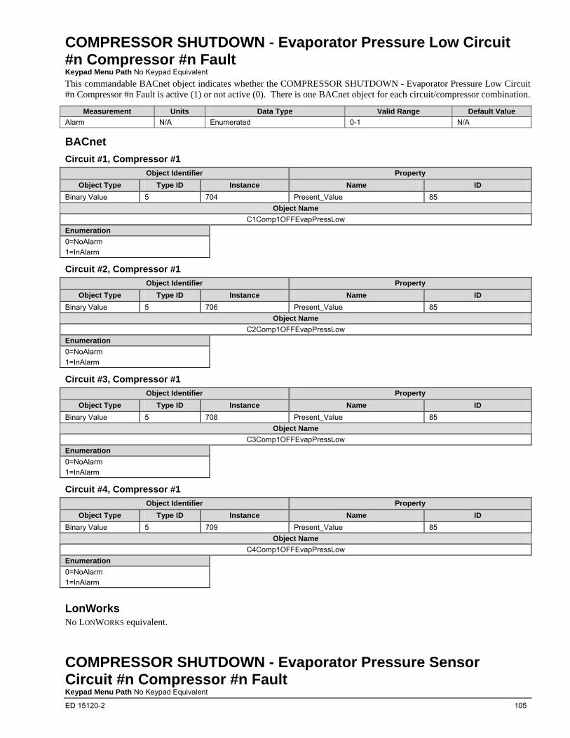
ED 15120-2 105
COMPRESSOR SHUTDOWN - Evaporator Pressure Low Circuit #n Compressor #n Fault Keypad Menu Path No Keypad Equivalent
This commandable BACnet object indicates whether the COMPRESSOR SHUTDOWN - Evaporator Pressure Low Circuit #n Compressor #n Fault is active (1) or not active (0). There is one BACnet object for each circuit/compressor combination.
Measurement Units Data Type Valid Range Default Value
Alarm N/A Enumerated 0-1 N/A
BACnet
Circuit #1, Compressor #1
Object Identifier Property
Object Type Type ID Instance Name ID
Binary Value 5 704 Present_Value 85
Object Name
C1Comp1OFFEvapPressLow
Enumeration
0=NoAlarm
1=InAlarm
Circuit #2, Compressor #1
Object Identifier Property
Object Type Type ID Instance Name ID
Binary Value 5 706 Present_Value 85
Object Name
C2Comp1OFFEvapPressLow
Enumeration
0=NoAlarm
1=InAlarm
Circuit #3, Compressor #1
Object Identifier Property
Object Type Type ID Instance Name ID
Binary Value 5 708 Present_Value 85
Object Name
C3Comp1OFFEvapPressLow
Enumeration
0=NoAlarm
1=InAlarm
Circuit #4, Compressor #1
Object Identifier Property
Object Type Type ID Instance Name ID
Binary Value 5 709 Present_Value 85
Object Name
C4Comp1OFFEvapPressLow
Enumeration
0=NoAlarm
1=InAlarm
LonWorks No LONWORKS equivalent.
COMPRESSOR SHUTDOWN - Evaporator Pressure Sensor Circuit #n Compressor #n Fault Keypad Menu Path No Keypad Equivalent
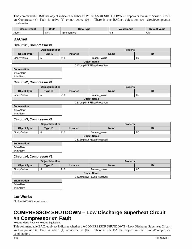
106 ED 15120-2
This commandable BACnet object indicates whether COMPRESSOR SHUTDOWN - Evaporator Pressure Sensor Circuit #n Compressor #n Fault is active (1) or not active (0). There is one BACnet object for each circuit/compressor combination.
Measurement Units Data Type Valid Range Default Value
Alarm N/A Enumerated 0-1 N/A
BACnet
Circuit #1, Compressor #1
Object Identifier Property
Object Type Type ID Instance Name ID
Binary Value 5 711 Present_Value 85
Object Name
C1Comp1OFFEvapPressSen
Enumeration
0=NoAlarm
1=InAlarm
Circuit #2, Compressor #1
Object Identifier Property
Object Type Type ID Instance Name ID
Binary Value 5 713 Present_Value 85
Object Name
C2Comp1OFFEvapPressSen
Enumeration
0=NoAlarm
1=InAlarm
Circuit #3, Compressor #1
Object Identifier Property
Object Type Type ID Instance Name ID
Binary Value 5 715 Present_Value 85
Object Name
C3Comp1OFFEvapPressSen
Enumeration
0=NoAlarm
1=InAlarm
Circuit #4, Compressor #1
Object Identifier Property
Object Type Type ID Instance Name ID
Binary Value 5 716 Present_Value 85
Object Name
C4Comp1OFFEvapPressSen
Enumeration
0=NoAlarm
1=InAlarm
LonWorks No LONWORKS equivalent.
COMPRESSOR SHUTDOWN – Low Discharge Superheat Circuit #n Compressor #n Fault Keypad Menu Path No Keypad Equivalent
This commandable BACnet object indicates whether the COMPRESSOR SHUTDOWN – Low Discharge Superheat Circuit #n Compressor #n Fault is active (1) or not active (0). There is one BACnet object for each circuit/compressor combination.
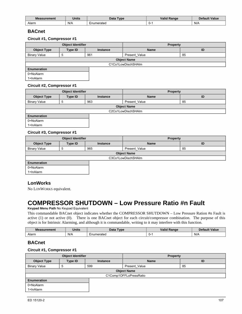
ED 15120-2 107
Measurement Units Data Type Valid Range Default Value
Alarm N/A Enumerated 0-1 N/A
BACnet
Circuit #1, Compressor #1
Object Identifier Property
Object Type Type ID Instance Name ID
Binary Value 5 961 Present_Value 85
Object Name
C1Co1LowDischSHAlm
Enumeration
0=NoAlarm
1=InAlarm
Circuit #2, Compressor #1
Object Identifier Property
Object Type Type ID Instance Name ID
Binary Value 5 963 Present_Value 85
Object Name
C2Co1LowDischSHAlm
Enumeration
0=NoAlarm
1=InAlarm
Circuit #3, Compressor #1
Object Identifier Property
Object Type Type ID Instance Name ID
Binary Value 5 965 Present_Value 85
Object Name
C3Co1LowDischSHAlm
Enumeration
0=NoAlarm
1=InAlarm
LonWorks No LONWORKS equivalent.
COMPRESSOR SHUTDOWN – Low Pressure Ratio #n Fault Keypad Menu Path No Keypad Equivalent
This commandable BACnet object indicates whether the COMPRESSOR SHUTDOWN – Low Pressure Ration #n Fault is active (1) or not active (0). There is one BACnet object for each circuit/compressor combination. The purpose of this object is for Intrinsic Alarming, and although it is commandable, writing to it may interfere with this function.
Measurement Units Data Type Valid Range Default Value
Alarm N/A Enumerated 0-1 N/A
BACnet
Circuit #1, Compressor #1
Object Identifier Property
Object Type Type ID Instance Name ID
Binary Value 5 599 Present_Value 85
Object Name
C1Comp1OFFLoPressRatio
Enumeration
0=NoAlarm
1=InAlarm

108 ED 15120-2
Circuit #2, Compressor #1
Object Identifier Property
Object Type Type ID Instance Name ID
Binary Value 5 601 Present_Value 85
Object Name
C2Comp1OFFLoPressRatio
Enumeration
0=NoAlarm
1=InAlarm
Circuit #3, Compressor #1
Object Identifier Property
Object Type Type ID Instance Name ID
Binary Value 5 603 Present_Value 85
Object Name
C3Comp1OFFLoPressRatio
Enumeration
0=NoAlarm
1=InAlarm
Circuit #4, Compressor #1
Object Identifier Property
Object Type Type ID Instance Name ID
Binary Value 5 604 Present_Value 85
Object Name
C4Comp1OFFLoPressRatio
Enumeration
0=NoAlarm
1=InAlarm
LonWorks No LONWORKS equivalent.
COMPRESSOR SHUTDOWN - Mechanical Low Pressure Trip Circuit #n Compressor #n Keypad Menu Path No Keypad Equivalent
This commandable BACnet object indicates whether the COMPRESSOR SHUTDOWN - Mechanical Low Pressure Trip Circuit #n Compressor #n Fault is active (1) or not active (0). There is one BACnet object for each circuit/compressor combination. The purpose of this object is for Intrinsic Alarming, and although it is commandable, writing to it may interfere with this function.
Measurement Units Data Type Valid Range Default Value
Alarm N/A Enumerated 0-1 N/A
BACnet
Circuit #1, Compressor #1
Object Identifier Property
Object Type Type ID Instance Name ID
Binary Value 5 876 Present_Value 85
Object Name
C1Comp1OFFMechLoPress
Enumeration
0=NoAlarm
1=InAlarm
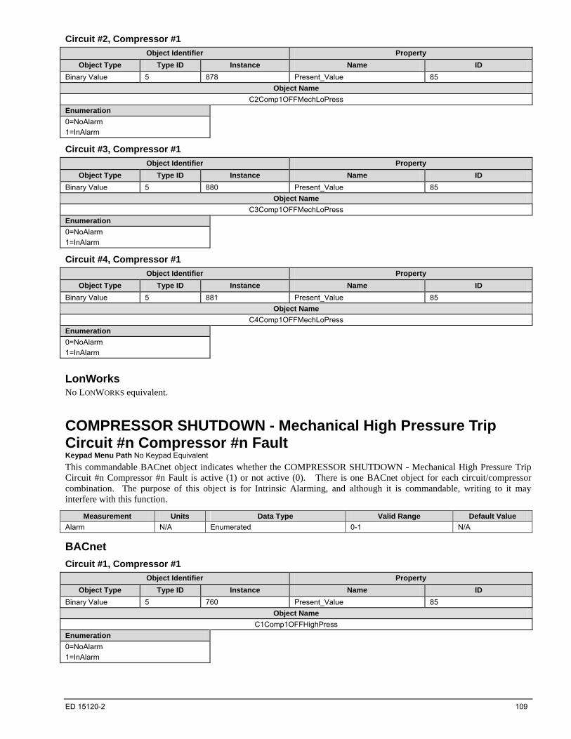
ED 15120-2 109
Circuit #2, Compressor #1
Object Identifier Property
Object Type Type ID Instance Name ID
Binary Value 5 878 Present_Value 85
Object Name
C2Comp1OFFMechLoPress
Enumeration
0=NoAlarm
1=InAlarm
Circuit #3, Compressor #1
Object Identifier Property
Object Type Type ID Instance Name ID
Binary Value 5 880 Present_Value 85
Object Name
C3Comp1OFFMechLoPress
Enumeration
0=NoAlarm
1=InAlarm
Circuit #4, Compressor #1
Object Identifier Property
Object Type Type ID Instance Name ID
Binary Value 5 881 Present_Value 85
Object Name
C4Comp1OFFMechLoPress
Enumeration
0=NoAlarm
1=InAlarm
LonWorks No LONWORKS equivalent.
COMPRESSOR SHUTDOWN - Mechanical High Pressure Trip Circuit #n Compressor #n Fault Keypad Menu Path No Keypad Equivalent
This commandable BACnet object indicates whether the COMPRESSOR SHUTDOWN - Mechanical High Pressure Trip Circuit #n Compressor #n Fault is active (1) or not active (0). There is one BACnet object for each circuit/compressor combination. The purpose of this object is for Intrinsic Alarming, and although it is commandable, writing to it may interfere with this function.
Measurement Units Data Type Valid Range Default Value
Alarm N/A Enumerated 0-1 N/A
BACnet
Circuit #1, Compressor #1
Object Identifier Property
Object Type Type ID Instance Name ID
Binary Value 5 760 Present_Value 85
Object Name
C1Comp1OFFHighPress
Enumeration
0=NoAlarm
1=InAlarm
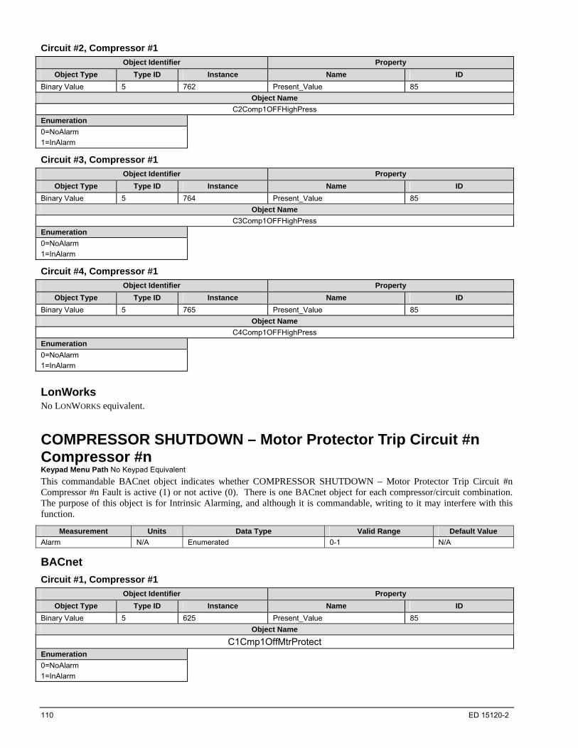
110 ED 15120-2
Circuit #2, Compressor #1
Object Identifier Property
Object Type Type ID Instance Name ID
Binary Value 5 762 Present_Value 85
Object Name
C2Comp1OFFHighPress
Enumeration
0=NoAlarm
1=InAlarm
Circuit #3, Compressor #1
Object Identifier Property
Object Type Type ID Instance Name ID
Binary Value 5 764 Present_Value 85
Object Name
C3Comp1OFFHighPress
Enumeration
0=NoAlarm
1=InAlarm
Circuit #4, Compressor #1
Object Identifier Property
Object Type Type ID Instance Name ID
Binary Value 5 765 Present_Value 85
Object Name
C4Comp1OFFHighPress
Enumeration
0=NoAlarm
1=InAlarm
LonWorks No LONWORKS equivalent.
COMPRESSOR SHUTDOWN – Motor Protector Trip Circuit #n Compressor #n Keypad Menu Path No Keypad Equivalent
This commandable BACnet object indicates whether COMPRESSOR SHUTDOWN – Motor Protector Trip Circuit #n Compressor #n Fault is active (1) or not active (0). There is one BACnet object for each compressor/circuit combination. The purpose of this object is for Intrinsic Alarming, and although it is commandable, writing to it may interfere with this function.
Measurement Units Data Type Valid Range Default Value
Alarm N/A Enumerated 0-1 N/A
BACnet
Circuit #1, Compressor #1
Object Identifier Property
Object Type Type ID Instance Name ID
Binary Value 5 625 Present_Value 85
Object Name
C1Cmp1OffMtrProtect Enumeration
0=NoAlarm
1=InAlarm
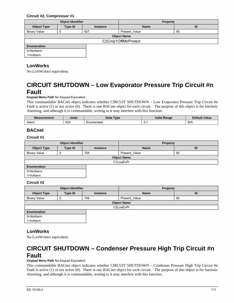
ED 15120-2 111
Circuit #2, Compressor #1
Object Identifier Property
Object Type Type ID Instance Name ID
Binary Value 5 627 Present_Value 85
Object Name
C2Cmp1OffMtrProtect Enumeration
0=NoAlarm
1=InAlarm
LonWorks No LONWORKS equivalent.
CIRCUIT SHUTDOWN – Low Evaporator Pressure Trip Circuit #n Fault Keypad Menu Path No Keypad Equivalent
This commandable BACnet object indicates whether CIRCUIT SHUTDOWN – Low Evaporator Pressure Trip Circuit #n Fault is active (1) or not active (0). There is one BACnet object for each circuit. The purpose of this object is for Intrinsic Alarming, and although it is commandable, writing to it may interfere with this function.
Measurement Units Data Type Valid Range Default Value
Alarm N/A Enumerated 0-1 N/A
BACnet
Circuit #1
Object Identifier Property
Object Type Type ID Instance Name ID
Binary Value 5 704 Present_Value 85
Object Name
C1LowEvPr
Enumeration
0=NoAlarm
1=InAlarm
Circuit #2
Object Identifier Property
Object Type Type ID Instance Name ID
Binary Value 5 706 Present_Value 85
Object Name
C2LowEvPr
Enumeration
0=NoAlarm
1=InAlarm
LonWorks No LONWORKS equivalent.
CIRCUIT SHUTDOWN – Condenser Pressure High Trip Circuit #n Fault Keypad Menu Path No Keypad Equivalent
This commandable BACnet object indicates whether CIRCUIT SHUTDOWN – Condenser Pressure High Trip Circuit #n Fault is active (1) or not active (0). There is one BACnet object for each circuit. The purpose of this object is for Intrinsic Alarming, and although it is commandable, writing to it may interfere with this function.

112 ED 15120-2
Measurement Units Data Type Valid Range Default Value
Alarm N/A Enumerated 0-1 N/A
BACnet
Circuit #1
Object Identifier Property
Object Type Type ID Instance Name ID
Binary Value 5 676 Present_Value 85
Object Name
C1OFFCondPressHi Enumeration
0=NoAlarm
1=InAlarm
Circuit #2
Object Identifier Property
Object Type Type ID Instance Name ID
Binary Value 5 678 Present_Value 85
Object Name
C2OFFCondPressHi Enumeration
0=NoAlarm
1=InAlarm
LonWorks No LONWORKS equivalent.
CIRCUIT SHUTDOWN – Evaporator Pressure Sensor Circuit #n Fault Keypad Menu Path No Keypad Equivalent
This commandable BACnet object indicates whether CIRCUIT SHUTDOWN – Evaporator Pressure Sensor Circuit #n Fault is active (1) or not active (0). There is one BACnet object for each circuit. The purpose of this object is for Intrinsic Alarming, and although it is commandable, writing to it may interfere with this function.
Measurement Units Data Type Valid Range Default Value
Alarm N/A Enumerated 0-1 N/A
BACnet
Circuit #1
Object Identifier Property
Object Type Type ID Instance Name ID
Binary Value 5 711 Present_Value 85
Object Name
C1EvapPsenf
Enumeration
0=NoAlarm
1=InAlarm

ED 15120-2 113
Circuit #2
Object Identifier Property
Object Type Type ID Instance Name ID
Binary Value 5 713 Present_Value 85
Object Name
C2EvapPsenf
Enumeration
0=NoAlarm
1=InAlarm
LonWorks No LONWORKS equivalent.
CIRCUIT SHUTDOWN – Condensor Pressure Sensor Circuit #n Fault Keypad Menu Path No Keypad Equivalent
This commandable BACnet object indicates whether CIRCUIT SHUTDOWN – Condensor Pressure Sensor Circuit #n Fault is active (1) or not active (0). There is one BACnet object for each circuit. The purpose of this object is for Intrinsic Alarming, and although it is commandable, writing to it may interfere with this function.
Measurement Units Data Type Valid Range Default Value
Alarm N/A Enumerated 0-1 N/A
BACnet
Circuit #1
Object Identifier Property
Object Type Type ID Instance Name ID
Binary Value 5 668 Present_Value 85
Object Name
C1CondPsenf
Enumeration
0=NoAlarm
1=InAlarm
Circuit #2
Object Identifier Property
Object Type Type ID Instance Name ID
Binary Value 5 670 Present_Value 85
Object Name
C2CondPsenf
Enumeration
0=NoAlarm
1=InAlarm
LonWorks No LONWORKS equivalent.
COMPRESSOR SHUTDOWN – Motor Temp Sensor Circuit #n Compressor #n Keypad Menu Path No Keypad Equivalent
This commandable BACnet object indicates whether COMPRESSOR SHUTDOWN – Motor Temp Sensor Circuit #n Compressor #n Fault is active (1) or not active (0). There is one BACnet object for each compressor/circuit combination. The purpose of this object is for Intrinsic Alarming, and although it is commandable, writing to it may interfere with this function.
Measurement Units Data Type Valid Range Default Value
Alarm N/A Enumerated 0-1 N/A
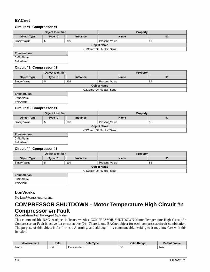
114 ED 15120-2
BACnet
Circuit #1, Compressor #1
Object Identifier Property
Object Type Type ID Instance Name ID
Binary Value 5 899 Present_Value 85
Object Name
C1Comp1OFFMotorTSens
Enumeration
0=NoAlarm
1=InAlarm
Circuit #2, Compressor #1
Object Identifier Property
Object Type Type ID Instance Name ID
Binary Value 5 901 Present_Value 85
Object Name
C2Comp1OFFMotorTSens
Enumeration
0=NoAlarm
1=InAlarm
Circuit #3, Compressor #1
Object Identifier Property
Object Type Type ID Instance Name ID
Binary Value 5 903 Present_Value 85
Object Name
C3Comp1OFFMotorTSens
Enumeration
0=NoAlarm
1=InAlarm
Circuit #4, Compressor #1
Object Identifier Property
Object Type Type ID Instance Name ID
Binary Value 5 904 Present_Value 85
Object Name
C4Comp1OFFMotorTSens
Enumeration
0=NoAlarm
1=InAlarm
LonWorks No LONWORKS equivalent.
COMPRESSOR SHUTDOWN - Motor Temperature High Circuit #n Compressor #n Fault Keypad Menu Path No Keypad Equivalent
This commandable BACnet object indicates whether COMPRESSOR SHUTDOWN Motor Temperature High Circuit #n Compressor #n Fault is active (1) or not active (0). There is one BACnet object for each compressor/circuit combination. The purpose of this object is for Intrinsic Alarming, and although it is commandable, writing to it may interfere with this function.
Measurement Units Data Type Valid Range Default Value
Alarm N/A Enumerated 0-1 N/A

ED 15120-2 115
BACnet
Circuit #1, Compressor #1
Object Identifier Property
Object Type Type ID Instance Name ID
Binary Value 5 637 Present_Value 85
Object Name
C1Comp1OFFMotorTempHi
Enumeration
0=NoAlarm
1=InAlarm
Circuit #2, Compressor #1
Object Identifier Property
Object Type Type ID Instance Name ID
Binary Value 5 639 Present_Value 85
Object Name
C2Comp1OFFMotorTempHi
Enumeration
0=NoAlarm
1=InAlarm
Circuit #3, Compressor #1
Object Identifier Property
Object Type Type ID Instance Name ID
Binary Value 5 641 Present_Value 85
Object Name
C3Comp1OFFMotorTempHi
Enumeration
0=NoAlarm
1=InAlarm
Circuit #4, Compressor #1
Object Identifier Property
Object Type Type ID Instance Name ID
Binary Value 5 642 Present_Value 85
Object Name
C4Comp1OFFMotorTempHi
Enumeration
0=NoAlarm
1=InAlarm
LonWorks No LONWORKS equivalent.
COMPRESSOR SHUTDOWN - No Pressure Change After Start Circuit #n Keypad Menu Path No Keypad Equivalent
This commandable BACnet object indicates whether COMPRESSOR SHUTDOWN - No Pressure Change After Start Circuit #n Fault is active (1) or not active (0). There is one BACnet object for each circuit. The purpose of this object is for Intrinsic Alarming, and although it is commandable, writing to it may interfere with this function.
Measurement Units Data Type Valid Range Default Value
Alarm N/A Enumerated 0-1 N/A
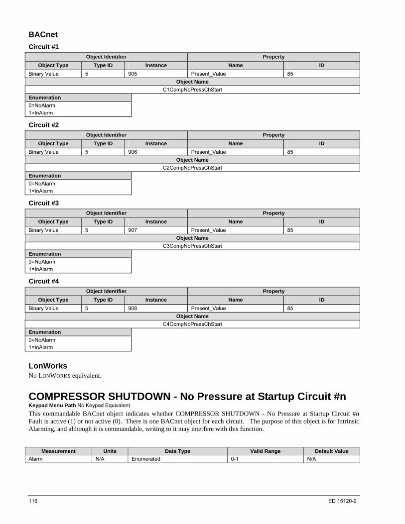
116 ED 15120-2
BACnet
Circuit #1
Object Identifier Property
Object Type Type ID Instance Name ID
Binary Value 5 905 Present_Value 85
Object Name
C1CompNoPressChStart
Enumeration
0=NoAlarm
1=InAlarm
Circuit #2
Object Identifier Property
Object Type Type ID Instance Name ID
Binary Value 5 906 Present_Value 85
Object Name
C2CompNoPressChStart
Enumeration
0=NoAlarm
1=InAlarm
Circuit #3
Object Identifier Property
Object Type Type ID Instance Name ID
Binary Value 5 907 Present_Value 85
Object Name
C3CompNoPressChStart
Enumeration
0=NoAlarm
1=InAlarm
Circuit #4
Object Identifier Property
Object Type Type ID Instance Name ID
Binary Value 5 908 Present_Value 85
Object Name
C4CompNoPressChStart
Enumeration
0=NoAlarm
1=InAlarm
LonWorks No LONWORKS equivalent.
COMPRESSOR SHUTDOWN - No Pressure at Startup Circuit #n Keypad Menu Path No Keypad Equivalent
This commandable BACnet object indicates whether COMPRESSOR SHUTDOWN - No Pressure at Startup Circuit #n Fault is active (1) or not active (0). There is one BACnet object for each circuit. The purpose of this object is for Intrinsic Alarming, and although it is commandable, writing to it may interfere with this function.
Measurement Units Data Type Valid Range Default Value
Alarm N/A Enumerated 0-1 N/A
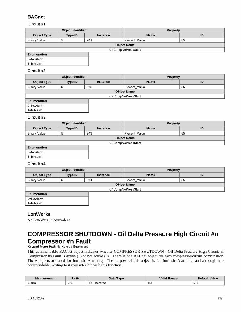
ED 15120-2 117
BACnet
Circuit #1
Object Identifier Property
Object Type Type ID Instance Name ID
Binary Value 5 911 Present_Value 85
Object Name
C1CompNoPressStart
Enumeration
0=NoAlarm
1=InAlarm
Circuit #2
Object Identifier Property
Object Type Type ID Instance Name ID
Binary Value 5 912 Present_Value 85
Object Name
C2CompNoPressStart
Enumeration
0=NoAlarm
1=InAlarm
Circuit #3
Object Identifier Property
Object Type Type ID Instance Name ID
Binary Value 5 913 Present_Value 85
Object Name
C3CompNoPressStart
Enumeration
0=NoAlarm
1=InAlarm
Circuit #4
Object Identifier Property
Object Type Type ID Instance Name ID
Binary Value 5 914 Present_Value 85
Object Name
C4CompNoPressStart
Enumeration
0=NoAlarm
1=InAlarm
LonWorks No LONWORKS equivalent.
COMPRESSOR SHUTDOWN - Oil Delta Pressure High Circuit #n Compressor #n Fault Keypad Menu Path No Keypad Equivalent
This commandable BACnet object indicates whether COMPRESSOR SHUTDOWN - Oil Delta Pressure High Circuit #n Compressor #n Fault is active (1) or not active (0). There is one BACnet object for each compressor/circuit combination. These objects are used for Intrinsic Alarming. The purpose of this object is for Intrinsic Alarming, and although it is commandable, writing to it may interfere with this function.
Measurement Units Data Type Valid Range Default Value
Alarm N/A Enumerated 0-1 N/A

118 ED 15120-2
BACnet
Circuit #1, Compressor #1
Object Identifier Property
Object Type Type ID Instance Name ID
Binary Value 5 796 Present_Value 85
Object Name
C1Comp1OFFOilFilterPHi
Enumeration
0=NoAlarm
1=InAlarm
Circuit #2, Compressor #1
Object Identifier Property
Object Type Type ID Instance Name ID
Binary Value 5 798 Present_Value 85
Object Name
C2Comp1OFFOilFilterPHi
Enumeration
0=NoAlarm
1=InAlarm
Circuit #3, Compressor #1
Object Identifier Property
Object Type Type ID Instance Name ID
Binary Value 5 800 Present_Value 85
Object Name
C3Comp1OFFOilFilterPHi
Enumeration
0=NoAlarm
1=InAlarm
Circuit #4, Compressor #1
Object Identifier Property
Object Type Type ID Instance Name ID
Binary Value 5 801 Present_Value 85
Object Name
C4Comp1OFFOilFilterPHi
Enumeration
0=NoAlarm
1=InAlarm
LonWorks No LONWORKS equivalent.
COMPRESSOR SHUTDOWN - Oil Feed Pressure Sensor Circuit #n Compressor #n Fault Keypad Menu Path No Keypad Equivalent
This commandable BACnet object indicates whether COMPRESSOR SHUTDOWN - Oil Feed Pressure Sensor Circuit #n Compressor #n Fault is active (1) or not active (0). There is one BACnet object for each compressor/circuit combination.
Measurement Units Data Type Valid Range Default Value
Alarm N/A Enumerated 0-1 N/A
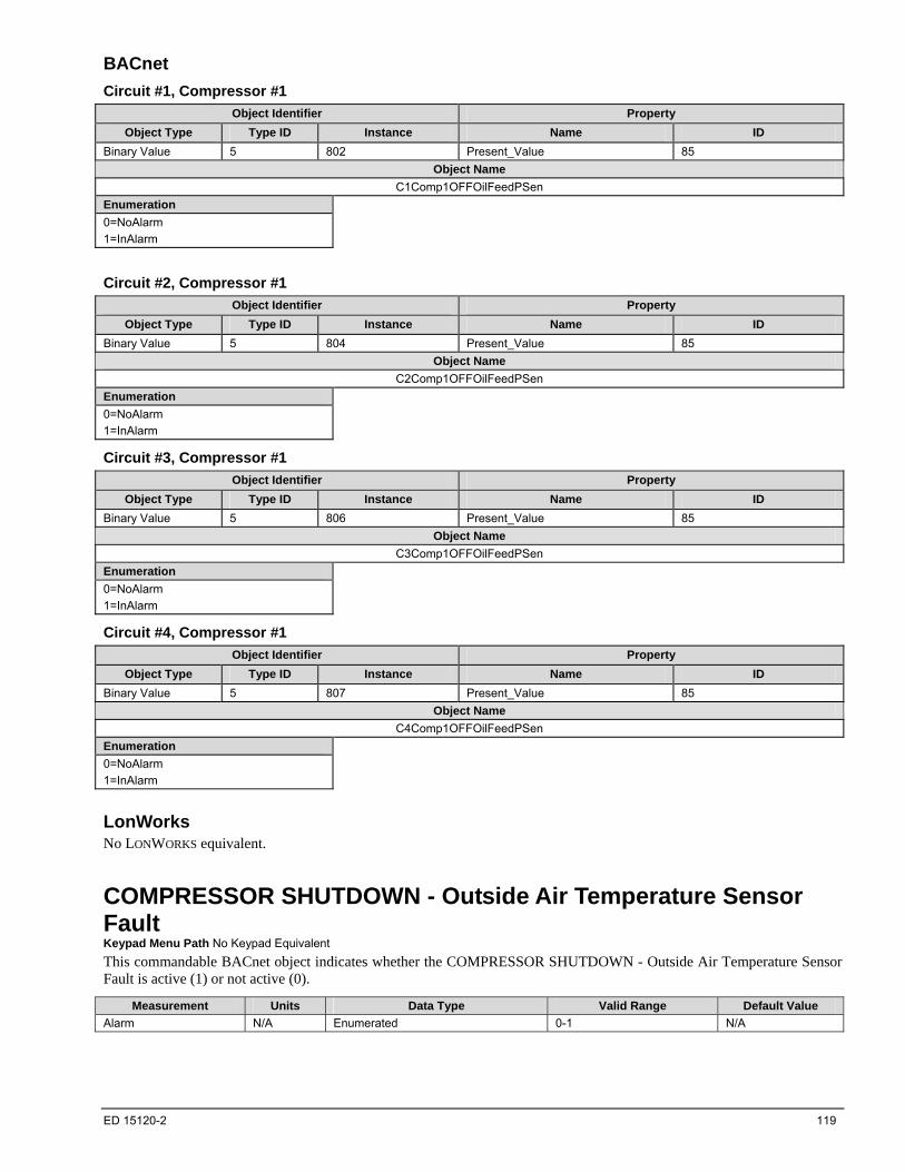
ED 15120-2 119
BACnet
Circuit #1, Compressor #1
Object Identifier Property
Object Type Type ID Instance Name ID
Binary Value 5 802 Present_Value 85
Object Name
C1Comp1OFFOilFeedPSen
Enumeration
0=NoAlarm
1=InAlarm
Circuit #2, Compressor #1
Object Identifier Property
Object Type Type ID Instance Name ID
Binary Value 5 804 Present_Value 85
Object Name
C2Comp1OFFOilFeedPSen
Enumeration
0=NoAlarm
1=InAlarm
Circuit #3, Compressor #1
Object Identifier Property
Object Type Type ID Instance Name ID
Binary Value 5 806 Present_Value 85
Object Name
C3Comp1OFFOilFeedPSen
Enumeration
0=NoAlarm
1=InAlarm
Circuit #4, Compressor #1
Object Identifier Property
Object Type Type ID Instance Name ID
Binary Value 5 807 Present_Value 85
Object Name
C4Comp1OFFOilFeedPSen
Enumeration
0=NoAlarm
1=InAlarm
LonWorks No LONWORKS equivalent.
COMPRESSOR SHUTDOWN - Outside Air Temperature Sensor Fault Keypad Menu Path No Keypad Equivalent
This commandable BACnet object indicates whether the COMPRESSOR SHUTDOWN - Outside Air Temperature Sensor Fault is active (1) or not active (0).
Measurement Units Data Type Valid Range Default Value
Alarm N/A Enumerated 0-1 N/A
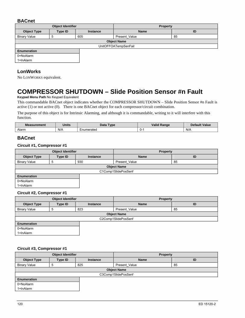
120 ED 15120-2
BACnet Object Identifier Property
Object Type Type ID Instance Name ID
Binary Value 5 605 Present_Value 85
Object Name
UnitOFFOATempSenFail
Enumeration
0=NoAlarm
1=InAlarm
LonWorks No LONWORKS equivalent.
COMPRESSOR SHUTDOWN – Slide Position Sensor #n Fault Keypad Menu Path No Keypad Equivalent
This commandable BACnet object indicates whether the COMPRESSOR SHUTDOWN – Slide Position Sensor #n Fault is active (1) or not active (0). There is one BACnet object for each compressor/circuit combination.
The purpose of this object is for Intrinsic Alarming, and although it is commandable, writing to it will interfere with this function.
Measurement Units Data Type Valid Range Default Value
Alarm N/A Enumerated 0-1 N/A
BACnet
Circuit #1, Compressor #1
Object Identifier Property
Object Type Type ID Instance Name ID
Binary Value 5 930 Present_Value 85
Object Name
C1Comp1SlidePosSenf
Enumeration
0=NoAlarm
1=InAlarm
Circuit #2, Compressor #1
Object Identifier Property
Object Type Type ID Instance Name ID
Binary Value 5 823 Present_Value 85
Object Name
C2Comp1SlidePosSenf
Enumeration
0=NoAlarm
1=InAlarm
Circuit #3, Compressor #1
Object Identifier Property
Object Type Type ID Instance Name ID
Binary Value 5 825 Present_Value 85
Object Name
C3Comp1SlidePosSenf
Enumeration
0=NoAlarm
1=InAlarm
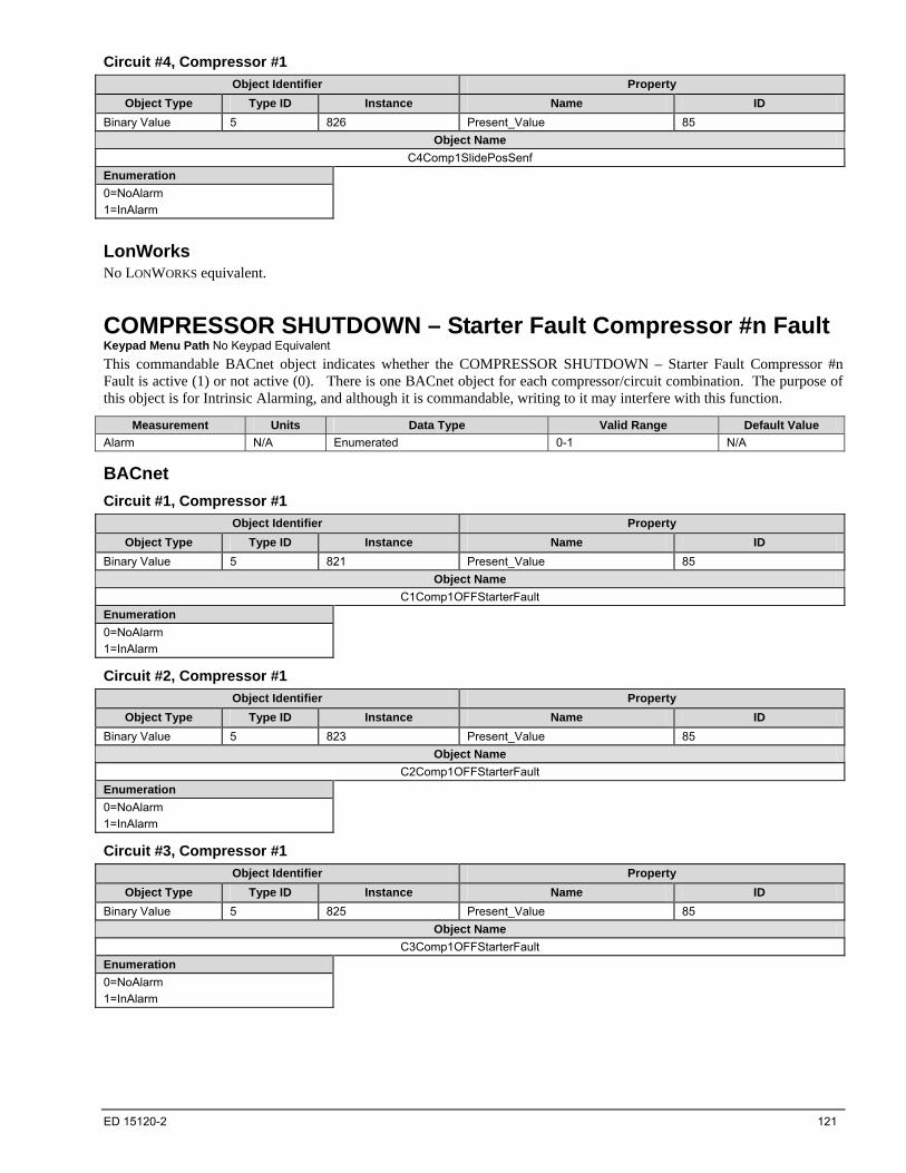
ED 15120-2 121
Circuit #4, Compressor #1
Object Identifier Property
Object Type Type ID Instance Name ID
Binary Value 5 826 Present_Value 85
Object Name
C4Comp1SlidePosSenf
Enumeration
0=NoAlarm
1=InAlarm
LonWorks No LONWORKS equivalent.
COMPRESSOR SHUTDOWN – Starter Fault Compressor #n Fault Keypad Menu Path No Keypad Equivalent
This commandable BACnet object indicates whether the COMPRESSOR SHUTDOWN – Starter Fault Compressor #n Fault is active (1) or not active (0). There is one BACnet object for each compressor/circuit combination. The purpose of this object is for Intrinsic Alarming, and although it is commandable, writing to it may interfere with this function.
Measurement Units Data Type Valid Range Default Value
Alarm N/A Enumerated 0-1 N/A
BACnet
Circuit #1, Compressor #1
Object Identifier Property
Object Type Type ID Instance Name ID
Binary Value 5 821 Present_Value 85
Object Name
C1Comp1OFFStarterFault
Enumeration
0=NoAlarm
1=InAlarm
Circuit #2, Compressor #1
Object Identifier Property
Object Type Type ID Instance Name ID
Binary Value 5 823 Present_Value 85
Object Name
C2Comp1OFFStarterFault
Enumeration
0=NoAlarm
1=InAlarm
Circuit #3, Compressor #1
Object Identifier Property
Object Type Type ID Instance Name ID
Binary Value 5 825 Present_Value 85
Object Name
C3Comp1OFFStarterFault
Enumeration
0=NoAlarm
1=InAlarm
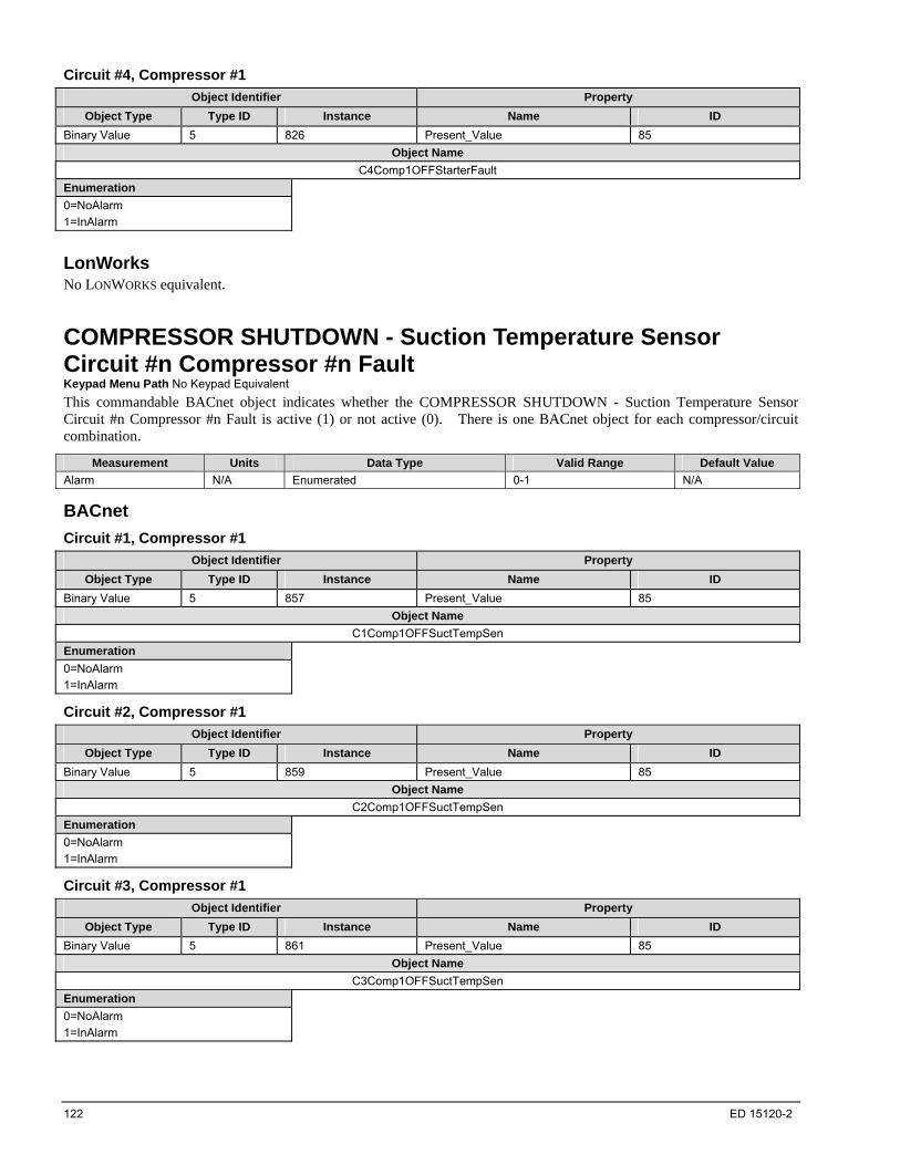
122 ED 15120-2
Circuit #4, Compressor #1
Object Identifier Property
Object Type Type ID Instance Name ID
Binary Value 5 826 Present_Value 85
Object Name
C4Comp1OFFStarterFault
Enumeration
0=NoAlarm
1=InAlarm
LonWorks No LONWORKS equivalent.
COMPRESSOR SHUTDOWN - Suction Temperature Sensor Circuit #n Compressor #n Fault Keypad Menu Path No Keypad Equivalent
This commandable BACnet object indicates whether the COMPRESSOR SHUTDOWN - Suction Temperature Sensor Circuit #n Compressor #n Fault is active (1) or not active (0). There is one BACnet object for each compressor/circuit combination.
Measurement Units Data Type Valid Range Default Value
Alarm N/A Enumerated 0-1 N/A
BACnet
Circuit #1, Compressor #1
Object Identifier Property
Object Type Type ID Instance Name ID
Binary Value 5 857 Present_Value 85
Object Name
C1Comp1OFFSuctTempSen
Enumeration
0=NoAlarm
1=InAlarm
Circuit #2, Compressor #1
Object Identifier Property
Object Type Type ID Instance Name ID
Binary Value 5 859 Present_Value 85
Object Name
C2Comp1OFFSuctTempSen
Enumeration
0=NoAlarm
1=InAlarm
Circuit #3, Compressor #1
Object Identifier Property
Object Type Type ID Instance Name ID
Binary Value 5 861 Present_Value 85
Object Name
C3Comp1OFFSuctTempSen
Enumeration
0=NoAlarm
1=InAlarm

ED 15120-2 123
Circuit #4, Compressor #1
Object Identifier Property
Object Type Type ID Instance Name ID
Binary Value 5 862 Present_Value 85
Object Name
C4Comp1OFFSuctTempSen
Enumeration
0=NoAlarm
1=InAlarm
LonWorks No LONWORKS equivalent.
Controller Board #n Offline Fault Keypad Menu Path No Keypad Equivalent
This commandable BACnet object indicates whether the Controller Board #n Offline Fault is active (1) or not active (0). There is one BACnet object for each circuit.
Measurement Units Data Type Valid Range Default Value
Alarm N/A Enumerated 0-1 N/A
BACnet
Unit
Object Identifier Property
Object Type Type ID Instance Name ID
Binary Value 5 925 Present_Value 85
Object Name UnitBoardOffline
Enumeration
0=NoAlarm
1=InAlarm
Circuit #1
Object Identifier Property
Object Type Type ID Instance Name ID
Binary Value 5 882 Present_Value 85
Object Name C1ControlBoardOffline
Enumeration
0=NoAlarm
1=InAlarm
Circuit #2
Object Identifier Property
Object Type Type ID Instance Name ID
Binary Value 5 883 Present_Value 85
Object Name C2ControlBoardOffline
Enumeration
0=NoAlarm
1=InAlarm

124 ED 15120-2
Circuit #3
Object Identifier Property
Object Type Type ID Instance Name ID
Binary Value 5 884 Present_Value 85
Object Name C3ControlBoardOffline
Enumeration
0=NoAlarm
1=InAlarm
Circuit #4
Object Identifier Property
Object Type Type ID Instance Name ID
Binary Value 5 885 Present_Value 85
Object Name C4ControlBoardOffline
Enumeration
0=NoAlarm
1=InAlarm
LonWorks No LONWORKS equivalent.
Evaporator Entering Water Temperature Sensor Fault Keypad Menu Path No Keypad Equivalent
This commandable BACnet object indicates whether the Evaporator Entering Water Temperature Sensor Fault alarm is active (1) or not active (0).
Measurement Units Data Type Valid Range Default Value
Alarm N/A Enumerated 0-1 N/A
BACnet Object Identifier Property
Object Type Type ID Instance Name ID
Binary Value 5 917 Present_Value 85
Object Name
EvapEntWTempSensorFail
Enumeration
0=NoAlarm
1=InAlarm
LonWorks No LONWORKS equivalent.
Evaporator Leaving Water Temperature 1 Sensor Fault Keypad Menu Path No Keypad Equivalent
This commandable BACnet object indicates whether the Evaporator Leaving Water Temparature 1 Sensor Fault alarm is active (1) or not active (0).
Measurement Units Data Type Valid Range Default Value
Alarm N/A Enumerated 0-1 N/A
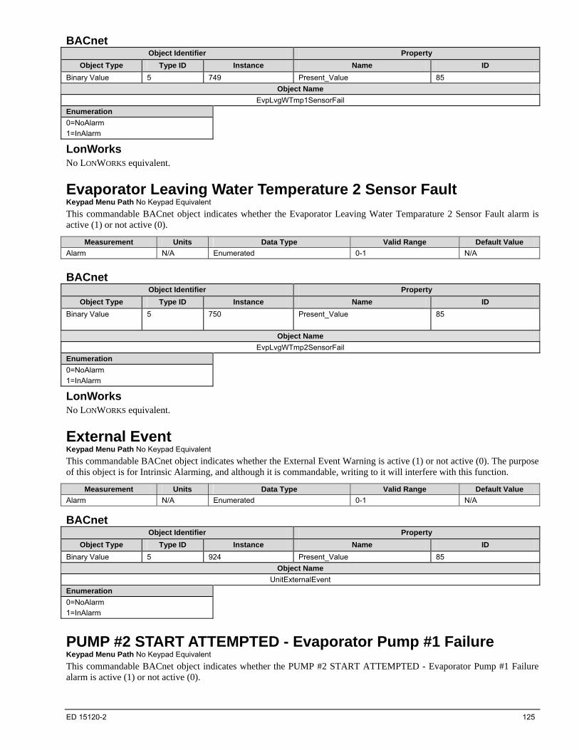
ED 15120-2 125
BACnet Object Identifier Property
Object Type Type ID Instance Name ID
Binary Value 5 749 Present_Value 85
Object Name
EvpLvgWTmp1SensorFail
Enumeration
0=NoAlarm
1=InAlarm
LonWorks No LONWORKS equivalent.
Evaporator Leaving Water Temperature 2 Sensor Fault Keypad Menu Path No Keypad Equivalent
This commandable BACnet object indicates whether the Evaporator Leaving Water Temparature 2 Sensor Fault alarm is active (1) or not active (0).
Measurement Units Data Type Valid Range Default Value
Alarm N/A Enumerated 0-1 N/A
BACnet Object Identifier Property
Object Type Type ID Instance Name ID
Binary Value 5 750
Present_Value 85
Object Name
EvpLvgWTmp2SensorFail
Enumeration
0=NoAlarm
1=InAlarm
LonWorks No LONWORKS equivalent.
External Event Keypad Menu Path No Keypad Equivalent
This commandable BACnet object indicates whether the External Event Warning is active (1) or not active (0). The purpose of this object is for Intrinsic Alarming, and although it is commandable, writing to it will interfere with this function.
Measurement Units Data Type Valid Range Default Value
Alarm N/A Enumerated 0-1 N/A
BACnet Object Identifier Property
Object Type Type ID Instance Name ID
Binary Value 5 924 Present_Value 85
Object Name
UnitExternalEvent
Enumeration
0=NoAlarm
1=InAlarm
PUMP #2 START ATTEMPTED - Evaporator Pump #1 Failure Keypad Menu Path No Keypad Equivalent
This commandable BACnet object indicates whether the PUMP #2 START ATTEMPTED - Evaporator Pump #1 Failure alarm is active (1) or not active (0).
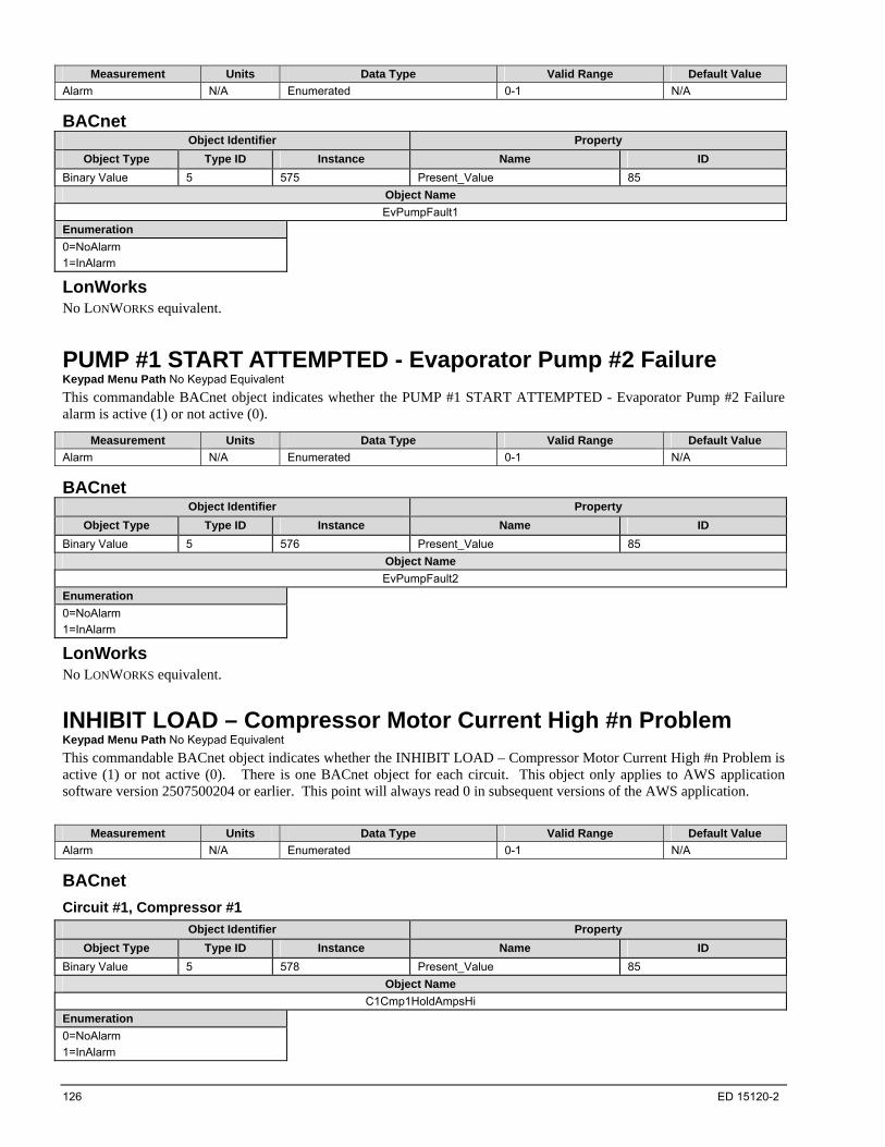
126 ED 15120-2
Measurement Units Data Type Valid Range Default Value
Alarm N/A Enumerated 0-1 N/A
BACnet Object Identifier Property
Object Type Type ID Instance Name ID
Binary Value 5 575 Present_Value 85
Object Name
EvPumpFault1
Enumeration
0=NoAlarm
1=InAlarm
LonWorks No LONWORKS equivalent.
PUMP #1 START ATTEMPTED - Evaporator Pump #2 Failure Keypad Menu Path No Keypad Equivalent
This commandable BACnet object indicates whether the PUMP #1 START ATTEMPTED - Evaporator Pump #2 Failure alarm is active (1) or not active (0).
Measurement Units Data Type Valid Range Default Value
Alarm N/A Enumerated 0-1 N/A
BACnet Object Identifier Property
Object Type Type ID Instance Name ID
Binary Value 5 576 Present_Value 85
Object Name
EvPumpFault2
Enumeration
0=NoAlarm
1=InAlarm
LonWorks No LONWORKS equivalent.
INHIBIT LOAD – Compressor Motor Current High #n Problem Keypad Menu Path No Keypad Equivalent
This commandable BACnet object indicates whether the INHIBIT LOAD – Compressor Motor Current High #n Problem is active (1) or not active (0). There is one BACnet object for each circuit. This object only applies to AWS application software version 2507500204 or earlier. This point will always read 0 in subsequent versions of the AWS application.
Measurement Units Data Type Valid Range Default Value
Alarm N/A Enumerated 0-1 N/A
BACnet
Circuit #1, Compressor #1
Object Identifier Property
Object Type Type ID Instance Name ID
Binary Value 5 578 Present_Value 85
Object Name
C1Cmp1HoldAmpsHi
Enumeration
0=NoAlarm
1=InAlarm

ED 15120-2 127
Circuit #2, Compressor #1
Object Identifier Property
Object Type Type ID Instance Name ID
Binary Value 5 580 Present_Value 85
Object Name
C2Cmp1HoldAmpsHi
Enumeration
0=NoAlarm
1=InAlarm
Circuit #3, Compressor #1
Object Identifier Property
Object Type Type ID Instance Name ID
Binary Value 5 582 Present_Value 85
Object Name
C3Cmp1HoldAmpsHi
Enumeration
0=NoAlarm
1=InAlarm
LonWorks No LONWORKS equivalent.
INHIBIT LOAD – Condenser Pressure High Circuit #n Problem Keypad Menu Path No Keypad Equivalent
This commandable BACnet object indicates whether the INHIBIT LOAD – Condenser Pressure High Circuit #n Problem is active (1) or not active (0). There is one BACnet object for each circuit. This object only applies to AWS application software version 2507500204 or earlier. This point will always read 0 in subsequent versions of the AWS application.
Measurement Units Data Type Valid Range Default Value
Alarm N/A Enumerated 0-1 N/A
BACnet
Circuit #1
Object Identifier Property
Object Type Type ID Instance Name ID
Binary Value 5 535 Present_Value 85
Object Name
C1InhbtLoadCondPressHi
Enumeration
0=NoAlarm
1=InAlarm
Circuit #2
Object Identifier Property
Object Type Type ID Instance Name ID
Binary Value 5 536 Present_Value 85
Object Name
C2InhbtLoadCondPressHi
Enumeration
0=NoAlarm
1=InAlarm
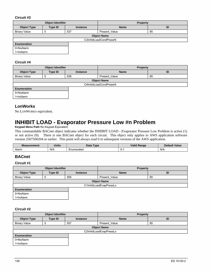
128 ED 15120-2
Circuit #3
Object Identifier Property
Object Type Type ID Instance Name ID
Binary Value 5 537 Present_Value 85
Object Name
C3InhbtLoadCondPressHi
Enumeration
0=NoAlarm
1=InAlarm
Circuit #4
Object Identifier Property
Object Type Type ID Instance Name ID
Binary Value 5 538 Present_Value 85
Object Name
C4InhbtLoadCondPressHi
Enumeration
0=NoAlarm
1=InAlarm
LonWorks No LONWORKS equivalent.
INHIBIT LOAD - Evaporator Pressure Low #n Problem Keypad Menu Path No Keypad Equivalent
This commandable BACnet object indicates whether the INHIBIT LOAD - Evaporator Pressure Low Problem is active (1) or not active (0). There is one BACnet object for each circuit. This object only applies to AWS application software version 2507500204 or earlier. This point will always read 0 in subsequent versions of the AWS application.
Measurement Units Data Type Valid Range Default Value
Alarm N/A Enumerated 0-1 N/A
BACnet
Circuit #1
Object Identifier Property
Object Type Type ID Instance Name ID
Binary Value 5 556 Present_Value 85
Object Name
C1InhbtLoadEvapPressLo
Enumeration
0=NoAlarm
1=InAlarm
Circuit #2
Object Identifier Property
Object Type Type ID Instance Name ID
Binary Value 5 557 Present_Value 85
Object Name
C2InhbtLoadEvapPressLo
Enumeration
0=NoAlarm
1=InAlarm
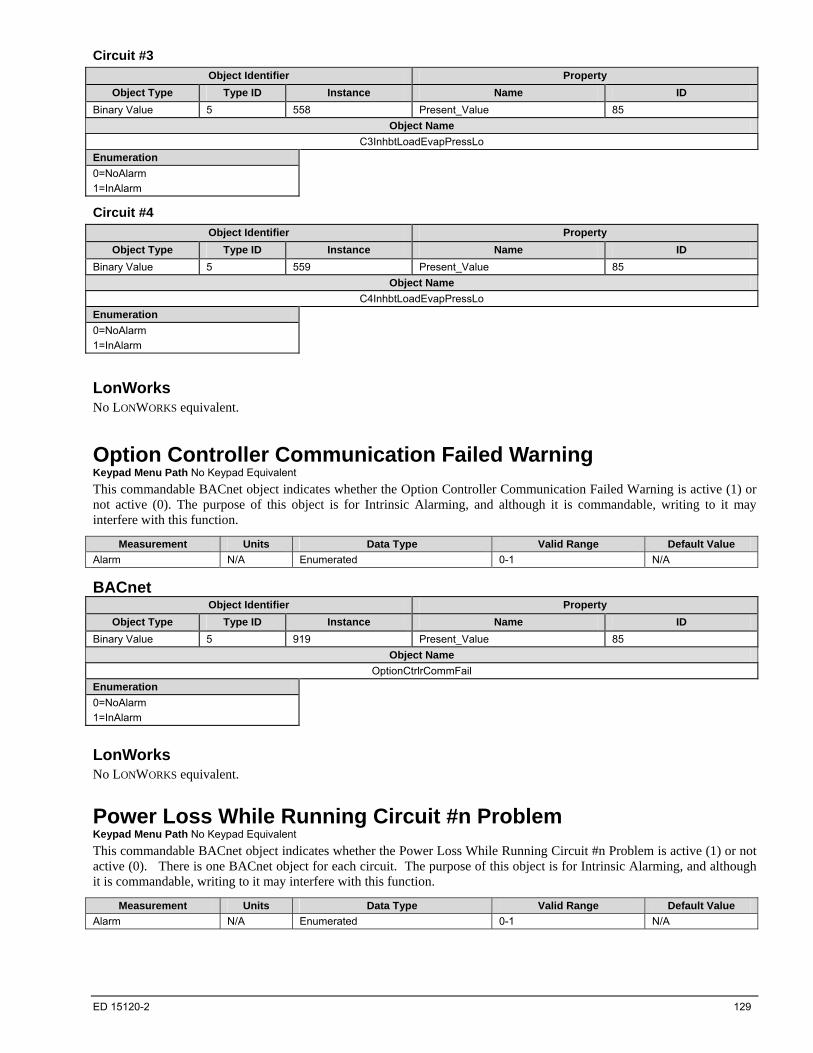
ED 15120-2 129
Circuit #3
Object Identifier Property
Object Type Type ID Instance Name ID
Binary Value 5 558 Present_Value 85
Object Name
C3InhbtLoadEvapPressLo
Enumeration
0=NoAlarm
1=InAlarm
Circuit #4
Object Identifier Property
Object Type Type ID Instance Name ID
Binary Value 5 559 Present_Value 85
Object Name
C4InhbtLoadEvapPressLo
Enumeration
0=NoAlarm
1=InAlarm
LonWorks No LONWORKS equivalent.
Option Controller Communication Failed Warning Keypad Menu Path No Keypad Equivalent
This commandable BACnet object indicates whether the Option Controller Communication Failed Warning is active (1) or not active (0). The purpose of this object is for Intrinsic Alarming, and although it is commandable, writing to it may interfere with this function.
Measurement Units Data Type Valid Range Default Value
Alarm N/A Enumerated 0-1 N/A
BACnet Object Identifier Property
Object Type Type ID Instance Name ID
Binary Value 5 919 Present_Value 85
Object Name
OptionCtrlrCommFail
Enumeration
0=NoAlarm
1=InAlarm
LonWorks No LONWORKS equivalent.
Power Loss While Running Circuit #n Problem Keypad Menu Path No Keypad Equivalent
This commandable BACnet object indicates whether the Power Loss While Running Circuit #n Problem is active (1) or not active (0). There is one BACnet object for each circuit. The purpose of this object is for Intrinsic Alarming, and although it is commandable, writing to it may interfere with this function.
Measurement Units Data Type Valid Range Default Value
Alarm N/A Enumerated 0-1 N/A
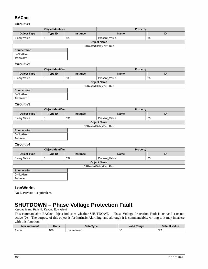
130 ED 15120-2
BACnet
Circuit #1
Object Identifier Property
Object Type Type ID Instance Name ID
Binary Value 5 529 Present_Value 85
Object Name
C1RestartDelayPwrLRun
Enumeration
0=NoAlarm
1=InAlarm
Circuit #2
Object Identifier Property
Object Type Type ID Instance Name ID
Binary Value 5 530 Present_Value 85
Object Name
C2RestartDelayPwrLRun
Enumeration
0=NoAlarm
1=InAlarm
Circuit #3
Object Identifier Property
Object Type Type ID Instance Name ID
Binary Value 5 531 Present_Value 85
Object Name
C3RestartDelayPwrLRun
Enumeration
0=NoAlarm
1=InAlarm
Circuit #4
Object Identifier Property
Object Type Type ID Instance Name ID
Binary Value 5 532 Present_Value 85
Object Name
C4RestartDelayPwrLRun
Enumeration
0=NoAlarm
1=InAlarm
LonWorks No LONWORKS equivalent.
SHUTDOWN – Phase Voltage Protection Fault Keypad Menu Path No Keypad Equivalent
This commandable BACnet object indicates whether SHUTDOWN – Phase Voltage Protection Fault is active (1) or not active (0). The purpose of this object is for Intrinsic Alarming, and although it is commandable, writing to it may interfere with this function.
Measurement Units Data Type Valid Range Default Value
Alarm N/A Enumerated 0-1 N/A

ED 15120-2 131
BACnet
Unit
Object Identifier Property
Object Type Type ID Instance Name ID
Binary Value 5 820 Present_Value 85
Object Name UnitOFFPhaseVoltage
Enumeration
0=NoAlarm
1=InAlarm
Circuit #1
Object Identifier Property
Object Type Type ID Instance Name ID
Binary Value 5 926 Present_Value 85
Object Name C1OFFPhaseVoltage
Enumeration
0=NoAlarm
1=InAlarm
Circuit #2
Object Identifier Property
Object Type Type ID Instance Name ID
Binary Value 5 927 Present_Value 85
Object Name C2OFFPhaseVoltage
Enumeration
0=NoAlarm
1=InAlarm
Circuit #3
Object Identifier Property
Object Type Type ID Instance Name ID
Binary Value 5 928 Present_Value 85
Object Name C3OFFPhaseVoltage
Enumeration
0=NoAlarm
1=InAlarm
Circuit #4
Object Identifier Property
Object Type Type ID Instance Name ID
Binary Value 5 929 Present_Value 85
Object Name C4OFFPhaseVoltage
Enumeration
0=NoAlarm
1=InAlarm
LonWorks No LONWORKS equivalent.
UNIT Power Restore Warning Keypad Menu Path No Keypad Equivalent
This commandable BACnet object is used for Intrinisic Alarming. It indicates whether the UNIT Power Restore Warning is active (1) or not active (0). The purpose of this object is for Intrinsic Alarming, and although it is commandable, writing to it will interfere with this function. This object only applies to AWS application software version 2507500204 or earlier. This point will always read 0 in subsequent versions of the AWS application.

132 ED 15120-2
Measurement Units Data Type Valid Range Default Value
Alarm N/A Enumerated 0-1 N/A
BACnet Object Identifier Property
Object Type Type ID Instance Name ID
Binary Value 5 515 Present_Value 85
Object Name
UnitPowerRestore
Enumeration
0=NoAlarm
1=InAlarm
LonWorks No LONWORKS equivalent.
UNIT SHUTDOWN - Evaporator Leaving Water Temperature Sensor Fault Keypad Menu Path No Keypad Equivalent
This commandable BACnet object indicates whether the COMPRESSOR SHUTDOWN - Evaporator Leaving Water Temperature Sensor Fault is active (1) or not active (0).
Measurement Units Data Type Valid Range Default Value
Alarm N/A Enumerated 0-1 N/A
BACnet Object Identifier Property
Object Type Type ID Instance Name ID
Binary Value 5 748 Present_Value 85
Object Name
UnitOFFEvapLvgWTempSen
Enumeration
0=NoAlarm
1=InAlarm
LonWorks No LONWORKS equivalent.
UNIT SHUTDOWN - Evaporator Water Flow Loss Fault Keypad Menu Path No Keypad Equivalent
This commandable BACnet object indicates whether the UNIT SHUTDOWN - Evaporator Water Flow Loss Fault is active (1) or not active (0). The purpose of this object is for Intrinsic Alarming, and although it is commandable, writing to it may interfere with this function.
Measurement Units Data Type Valid Range Default Value
Alarm N/A Enumerated 0-1 N/A
BACnet Object Identifier Property
Object Type Type ID Instance Name ID
Binary Value 5 701 Present_Value 85
Object Name
UnitOFFEvapWaterFlow
Enumeration
0=NoAlarm
1=InAlarm

ED 15120-2 133
LonWorks No LONWORKS equivalent.
UNIT STOP - Emergency Stop Alarm Keypad Menu Path No Keypad Equivalent
This commandable BACnet object indicates whether the UNIT STOP - Emergency Stop Alarm Fault is active (1) or not active (0). The purpose of this object is for Intrinsic Alarming, and although it is commandable, writing to it may interfere with this function.
Measurement Units Data Type Valid Range Default Value
Alarm N/A Enumerated 0-1 N/A
BACnet Object Identifier Property
Object Type Type ID Instance Name ID
Binary Value 5 921 Present_Value 85
Object Name
EmergencyStopAlarm
Enumeration
0=NoAlarm
1=InAlarm
LonWorks No LONWORKS equivalent.
UNIT STOP - Evaporator Water Temperatures Inverted Keypad Menu Path No Keypad Equivalent
This commandable BACnet object indicates whether the UNIT STOP - Evaporator Water Temperatures Inverted Fault is active (1) or not active (0). The purpose of this object is for Intrinsic Alarming, and although it is commandable, writing to it may interfere with this function.
Measurement Units Data Type Valid Range Default Value
Alarm N/A Enumerated 0-1 N/A
BACnet Object Identifier Property
Object Type Type ID Instance Name ID
Binary Value 5 922 Present_Value 85
Object Name
EvapWTempInverted
Enumeration
0=NoAlarm
1=InAlarm
LonWorks No LONWORKS equivalent.
UNIT STOP – External Alarm Keypad Menu Path No Keypad Equivalent
This commandable BACnet object indicates whether the UNIT STOP – External Alarm Fault is active (1) or not active (0). The purpose of this object is for Intrinsic Alarming, and although it is commandable, writing to it may interfere with this function.
Measurement Units Data Type Valid Range Default Value
Alarm N/A Enumerated 0-1 N/A
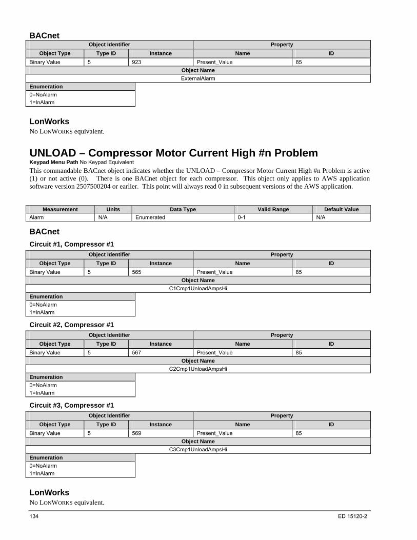
134 ED 15120-2
BACnet Object Identifier Property
Object Type Type ID Instance Name ID
Binary Value 5 923 Present_Value 85
Object Name
ExternalAlarm
Enumeration
0=NoAlarm
1=InAlarm
LonWorks No LONWORKS equivalent.
UNLOAD – Compressor Motor Current High #n Problem Keypad Menu Path No Keypad Equivalent
This commandable BACnet object indicates whether the UNLOAD – Compressor Motor Current High #n Problem is active (1) or not active (0). There is one BACnet object for each compressor. This object only applies to AWS application software version 2507500204 or earlier. This point will always read 0 in subsequent versions of the AWS application.
Measurement Units Data Type Valid Range Default Value
Alarm N/A Enumerated 0-1 N/A
BACnet
Circuit #1, Compressor #1
Object Identifier Property
Object Type Type ID Instance Name ID
Binary Value 5 565 Present_Value 85
Object Name
C1Cmp1UnloadAmpsHi
Enumeration
0=NoAlarm
1=InAlarm
Circuit #2, Compressor #1
Object Identifier Property
Object Type Type ID Instance Name ID
Binary Value 5 567 Present_Value 85
Object Name
C2Cmp1UnloadAmpsHi
Enumeration
0=NoAlarm
1=InAlarm
Circuit #3, Compressor #1
Object Identifier Property
Object Type Type ID Instance Name ID
Binary Value 5 569 Present_Value 85
Object Name
C3Cmp1UnloadAmpsHi
Enumeration
0=NoAlarm
1=InAlarm
LonWorks No LONWORKS equivalent.

ED 15120-2 135
UNLOAD – Condenser Pressure High #n Problem Keypad Menu Path No Keypad Equivalent
This commandable BACnet object indicates whether the UNLOAD – Condenser Pressure High #n Problem is active (1) or not active (0). There is one BACnet object for each circuit. This object only applies to AWS application software version 2507500204 or earlier. This point will always read 0 in subsequent versions of the AWS application.
Measurement Units Data Type Valid Range Default Value
Alarm N/A Enumerated 0-1 N/A
BACnet
Circuit #1
Object Identifier Property
Object Type Type ID Instance Name ID
Binary Value 5 540 Present_Value 85
Object Name
C1UnloadCondPressHi
Enumeration
0=NoAlarm
1=InAlarm
Circuit #2
Object Identifier Property
Object Type Type ID Instance Name ID
Binary Value 5 541 Present_Value 85
Object Name
C2UnloadCondPressHi
Enumeration
0=NoAlarm
1=InAlarm
Circuit #3
Object Identifier Property
Object Type Type ID Instance Name ID
Binary Value 5 542 Present_Value 85
Object Name
C3UnloadCondPressHi
Enumeration
0=NoAlarm
1=InAlarm
Circuit #4
Object Identifier Property
Object Type Type ID Instance Name ID
Binary Value 5 543 Present_Value 85
Object Name
C4UnloadCondPressHi
Enumeration
0=NoAlarm
1=InAlarm
LonWorks No LONWORKS equivalent.
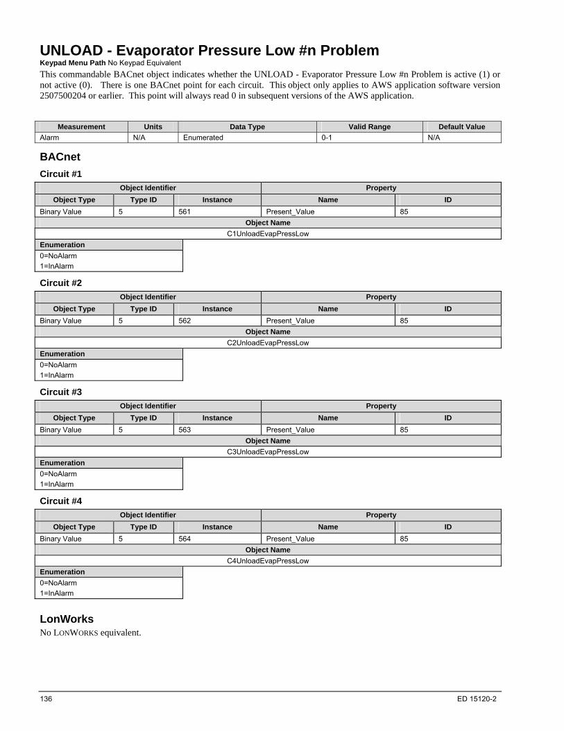
136 ED 15120-2
UNLOAD - Evaporator Pressure Low #n Problem Keypad Menu Path No Keypad Equivalent
This commandable BACnet object indicates whether the UNLOAD - Evaporator Pressure Low #n Problem is active (1) or not active (0). There is one BACnet point for each circuit. This object only applies to AWS application software version 2507500204 or earlier. This point will always read 0 in subsequent versions of the AWS application.
Measurement Units Data Type Valid Range Default Value
Alarm N/A Enumerated 0-1 N/A
BACnet
Circuit #1
Object Identifier Property
Object Type Type ID Instance Name ID
Binary Value 5 561 Present_Value 85
Object Name
C1UnloadEvapPressLow
Enumeration
0=NoAlarm
1=InAlarm
Circuit #2
Object Identifier Property
Object Type Type ID Instance Name ID
Binary Value 5 562 Present_Value 85
Object Name
C2UnloadEvapPressLow
Enumeration
0=NoAlarm
1=InAlarm
Circuit #3
Object Identifier Property
Object Type Type ID Instance Name ID
Binary Value 5 563 Present_Value 85
Object Name
C3UnloadEvapPressLow
Enumeration
0=NoAlarm
1=InAlarm
Circuit #4
Object Identifier Property
Object Type Type ID Instance Name ID
Binary Value 5 564 Present_Value 85
Object Name
C4UnloadEvapPressLow
Enumeration
0=NoAlarm
1=InAlarm
LonWorks No LONWORKS equivalent.
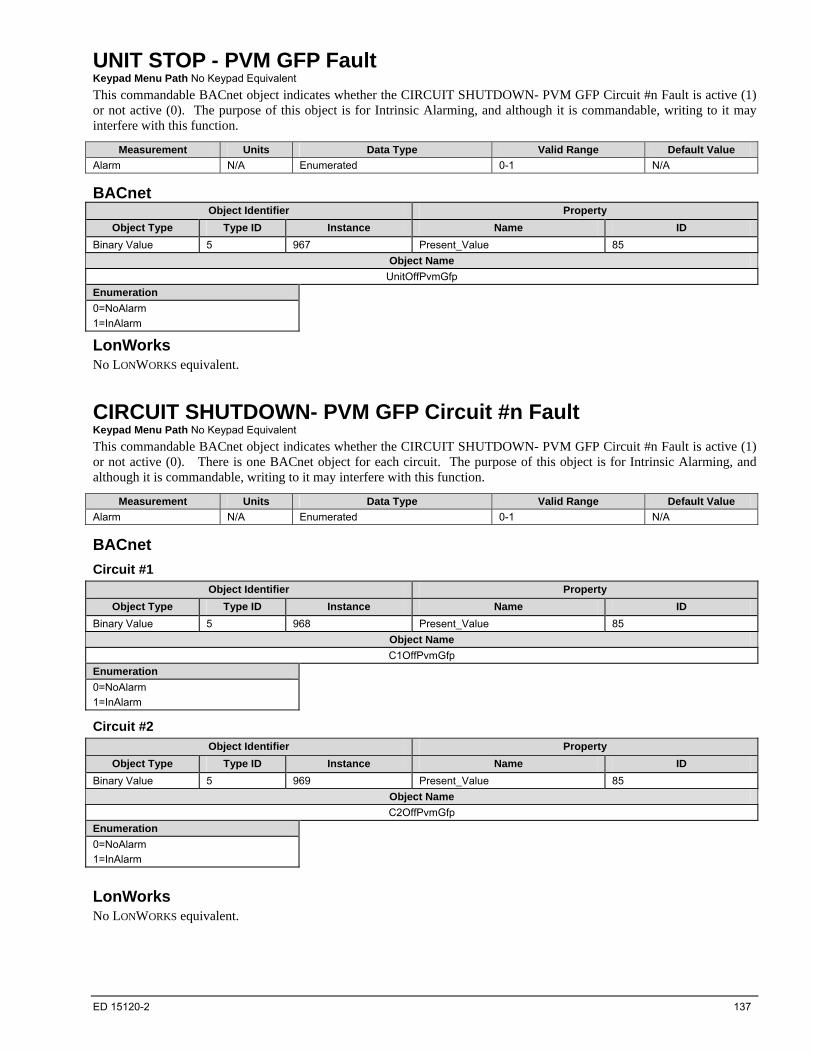
ED 15120-2 137
UNIT STOP - PVM GFP Fault Keypad Menu Path No Keypad Equivalent
This commandable BACnet object indicates whether the CIRCUIT SHUTDOWN- PVM GFP Circuit #n Fault is active (1) or not active (0). The purpose of this object is for Intrinsic Alarming, and although it is commandable, writing to it may interfere with this function.
Measurement Units Data Type Valid Range Default Value
Alarm N/A Enumerated 0-1 N/A
BACnet Object Identifier Property
Object Type Type ID Instance Name ID
Binary Value 5 967 Present_Value 85
Object Name
UnitOffPvmGfp
Enumeration
0=NoAlarm
1=InAlarm
LonWorks No LONWORKS equivalent.
CIRCUIT SHUTDOWN- PVM GFP Circuit #n Fault Keypad Menu Path No Keypad Equivalent
This commandable BACnet object indicates whether the CIRCUIT SHUTDOWN- PVM GFP Circuit #n Fault is active (1) or not active (0). There is one BACnet object for each circuit. The purpose of this object is for Intrinsic Alarming, and although it is commandable, writing to it may interfere with this function.
Measurement Units Data Type Valid Range Default Value
Alarm N/A Enumerated 0-1 N/A
BACnet
Circuit #1
Object Identifier Property
Object Type Type ID Instance Name ID
Binary Value 5 968 Present_Value 85
Object Name
C1OffPvmGfp
Enumeration
0=NoAlarm
1=InAlarm
Circuit #2
Object Identifier Property
Object Type Type ID Instance Name ID
Binary Value 5 969 Present_Value 85
Object Name
C2OffPvmGfp
Enumeration
0=NoAlarm
1=InAlarm
LonWorks No LONWORKS equivalent.

138 ED 15120-2
LONWORKS Device Management
The following functions are specific to the LONWORKS device (in this case, the LONWORKS communication module). These functions are used for maintenance and testing. A network management tool such as Echelon’s LonMaker® is typically used to issue the network commands.
Offline When the LONWORKS Communication Module receives a network command to go Offline, the unit controller continues to operate but LONWORKS communication is suspended except for network management messages.
Online When the LONWORKS Communication Module receives a network command to go Online, LONWORKS network messaging is restored.
Reset When the LONWORKS Communication Module receives a network command Reset command, it performs the following: 1. Send a command to the unit controller to perform a warm reset, maintaining non-volatile memory. 2. Reset the Neuron processor.
Wink The wink function is not supported.

ED 15120-2 139
BACnet Device Management
The following functions are specific to the BACnet device. These functions are used for maintenance and testing. A network management tool such as VTS is typically used to issue the network commands.
DeviceCommunicationControl - Disable The purpose of this command is to reduce network traffic for diagnostic testing of the BACnet network. When the BACnet Communication Module receives a network command to Disable communications, it stops passing information to the network. It is possible to specify an optional length of time that communication is suspended. The unit continues to operate during the Disabled state.
DeviceCommunicationControl - Enable When the BACnet Communication Module receives a network command to Enable communications, chiller communication to the BACnet network is restored.
ReinitializeDevice (Reset) When the BACnet Communication Module is capable of receiving a network ReinitializeDevice command to reboot itself (cold start or warm start). The funcationality of a cold and warm start are the same and simply reboot the BACnet Communication Module. No password is required.
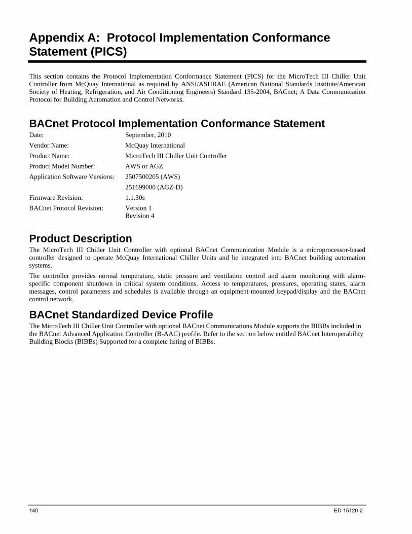
140 ED 15120-2
Appendix A: Protocol Implementation Conformance Statement (PICS)
This section contains the Protocol Implementation Conformance Statement (PICS) for the MicroTech III Chiller Unit Controller from McQuay International as required by ANSI/ASHRAE (American National Standards Institute/American Society of Heating, Refrigeration, and Air Conditioning Engineers) Standard 135-2004, BACnet; A Data Communication Protocol for Building Automation and Control Networks.
BACnet Protocol Implementation Conformance Statement Date: September, 2010
Vendor Name: McQuay International
Product Name: MicroTech III Chiller Unit Controller
Product Model Number: AWS or AGZ
Application Software Versions: 2507500205 (AWS)
251699000 (AGZ-D)
Firmware Revision: 1.1.30s
BACnet Protocol Revision: Version 1 Revision 4
Product Description The MicroTech III Chiller Unit Controller with optional BACnet Communication Module is a microprocessor-based controller designed to operate McQuay International Chiller Units and be integrated into BACnet building automation systems.
The controller provides normal temperature, static pressure and ventilation control and alarm monitoring with alarm-specific component shutdown in critical system conditions. Access to temperatures, pressures, operating states, alarm messages, control parameters and schedules is available through an equipment-mounted keypad/display and the BACnet control network.
BACnet Standardized Device Profile The MicroTech III Chiller Unit Controller with optional BACnet Communications Module supports the BIBBs included in the BACnet Advanced Application Controller (B-AAC) profile. Refer to the section below entitled BACnet Interoperability Building Blocks (BIBBs) Supported for a complete listing of BIBBs.

ED 15120-2 141
BACnet Interoperability Building Blocks (BIBBs) Supported BIBB Name Designation
Data Sharing – ReadProperty – B DS-RP-B
Data Sharing – ReadPropertyMultiple – B DS-RPM-B
Data Sharing – WriteProperty – B DS-WP-B
Data Sharing – WritePropertyMultiple – B DS-WPM-B
Data Sharing – COV – B DS-COV-B
Data Sharing – ReadProperty – A DS-RP-A
Data Sharing – WriteProperty – A DS-WP-A
Data Sharing – COV – A DS-COV-A
Alarm & Event – Notification Internal - B AE-N-I-B
Alarm & Event – ACK –B AE-ACK-B
Alarm & Event – Information - B AE-INFO-B
Alarm & Event – Alarm Summary - B AE-ASUM-B
Scheduling – Internal - B SCHED-I-B
Device Management – Dynamic Device Binding – A DM-DDB-A
Device Management – Dynamic Device Binding – B DM-DDB-B
Device Management – Dynamic Object Binding – B DM-DOB-B
Device Management – Device Communication Control – B DM-DCC-B
Device Management – TimeSynchronization – B DM-TS-B
Device Management – UTCTimeSynchronization – B DM-UTS-B
Device Management – Reinitialize Device – B DM-RD-B
Device Management – List Manipulation – B DM-LM-B
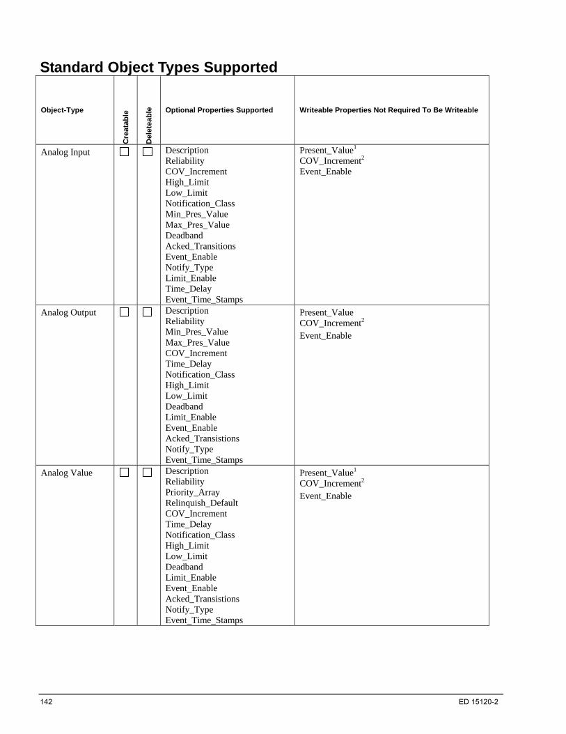
142 ED 15120-2
Standard Object Types Supported
Object-Type
Cre
atab
le
Del
etea
ble
Optional Properties Supported Writeable Properties Not Required To Be Writeable
Analog Input Description Reliability COV_Increment High_Limit Low_Limit Notification_Class Min_Pres_Value Max_Pres_Value Deadband Acked_Transitions Event_Enable Notify_Type Limit_Enable Time_Delay Event_Time_Stamps
Present_Value1 COV_Increment2 Event_Enable
Analog Output Description Reliability Min_Pres_Value Max_Pres_Value COV_Increment Time_Delay Notification_Class High_Limit Low_Limit Deadband Limit_Enable Event_Enable Acked_Transistions Notify_Type Event_Time_Stamps
Present_Value COV_Increment2 Event_Enable
Analog Value Description Reliability Priority_Array Relinquish_Default COV_Increment Time_Delay Notification_Class High_Limit Low_Limit Deadband Limit_Enable Event_Enable Acked_Transistions Notify_Type Event_Time_Stamps
Present_Value1 COV_Increment2 Event_Enable
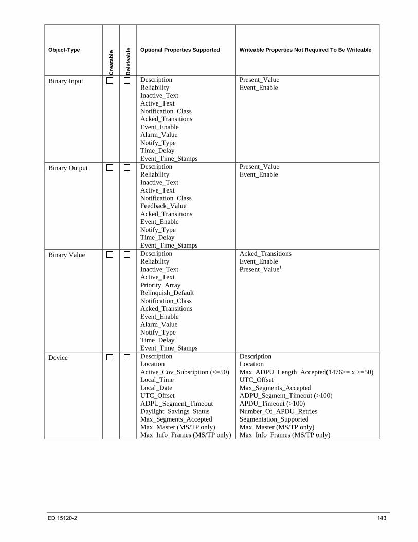
ED 15120-2 143
Object-Type
Cre
atab
le
Del
etea
ble
Optional Properties Supported Writeable Properties Not Required To Be Writeable
Binary Input Description Reliability Inactive_Text Active_Text Notification_Class Acked_Transitions Event_Enable Alarm_Value Notify_Type Time_Delay Event_Time_Stamps
Present_Value Event_Enable
Binary Output Description Reliability Inactive_Text Active_Text Notification_Class Feedback_Value Acked_Transitions Event_Enable Notify_Type Time_Delay Event_Time_Stamps
Present_Value Event_Enable
Binary Value Description Reliability Inactive_Text Active_Text Priority_Array Relinquish_Default Notification_Class Acked_Transitions Event_Enable Alarm_Value Notify_Type Time_Delay Event_Time_Stamps
Acked_Transitions Event_Enable Present_Value1
Device Description Location Active_Cov_Subsription (<=50) Local_Time Local_Date UTC_Offset ADPU_Segment_Timeout Daylight_Savings_Status Max_Segments_Accepted Max_Master (MS/TP only) Max_Info_Frames (MS/TP only)
Description Location Max_ADPU_Length_Accepted(1476>= x >=50)UTC_Offset Max_Segments_Accepted ADPU_Segment_Timeout (>100) APDU_Timeout (>100) Number_Of_APDU_Retries Segmentation_Supported Max_Master (MS/TP only) Max_Info_Frames (MS/TP only)

144 ED 15120-2
Object-Type
Cre
atab
le
Del
etea
ble
Optional Properties Supported Writeable Properties Not Required To Be Writeable
Multi-State Input Description State_Text Notification_Class Acked_Transitions Event_Enable Notify_Type Time_Delay Alarm_Values Fault_Values Reliability Event_Time_Stamps
Multi-State Output
Description Reliability State_Text Notification_Class Acked_Transitions Event_Enable Notify_Type Time_Delay Event_Time_Stamps Feedback_Value
Event_Enable
Multi-State Value Description Priority_Array Relinquish_Default Notification_Class Reliability Acked_Transitions Event_Enable Alarm_Values Fault_Values Notify_Type Time_Delay Event_Time_Stamps State_Text
Present_Value1
Event_Enable
Notification Class Description Object_Name Description Recipient_List (Max 20) Priority Ack_Required
Calendar Description Date_List (Max 10)
Schedule Weekly_Schedule Exception_Schedule
Object_Name Effective_Period Weekly_Schedule Exception_Schedule List_Of_Object_Property_Refs
1 Some objects of this type are read only. For those objects, the Present_Value is not commandable or writable. 2 Changes to this property do not take effect until the power is cycled on the unit controller. After changing COV_Increment, you must wait at least one minute before cycling power. Otherewise, this change will not be saved.

ED 15120-2 145
Data Link Layer Options BACnet IP, (Annex J)
BACnet IP, (Annex J), Foreign Device
MS/TP master (Clause 9), baud rate(s): 9600, 19200, 38400, 76800
MS/TP slave (Clause 9), baud rate(s): 9600, 19200, 38400, 76800
Segmentation Capability Segmented requests supported Window Size: 4 for IP and 1 for MS/TP
Segmented responses supported Window Size: 4 for IP and 1 for MS/TP
Device Address Binding Static Device Binding
Yes
No
Networking Options Router, Clause 6 – List all routing configurations, e.g., ARCNET-Ethernet, Ethernet-MS/TP,
etc.
Annex H, BACnet Tunneling Router over IP
BACnet/IP Broadcast Management Device (BBMD)
Number of BDT entries:
Does the BBMD Support registration by Foreign Devices? Yes No
Character Sets Supported ANSI X3.4 IBM/Microsoft DBCS ISO 8859-1
ISO 10646 (UCS-2) ISO 10646 (UCS-4) JIS C 6226
Note: Support for multiple character sets does not imply they can be supported simultaneously.
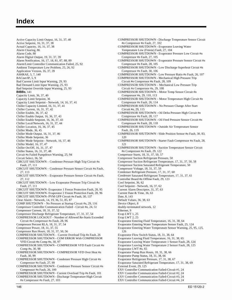
146 ED 15120-2
Index
Active Capacity Limit Output, 16, 31, 37, 40 Active Setpoint, 16, 31, 37, 38 Actual Capacity, 16, 31, 37, 38 Alarm Clearing, 86 Alarm Code, 80 Alarm Digital Output, 19, 31, 37, 39 Alarm Notification, 16, 17, 18, 81, 87, 88, 89 Alarm/Limit Controller Communication Failed, 25, 92 Ambient Temperature Low Problem, 25, 26, 92 Application Version, 16, 37, 39 ASHRAE, 5, 7, 140 BACnet/IP, 5, 9 Bad Current Limit Input Warning, 29, 93 Bad Demand Limit Input Warning, 25, 93 Bad Setpoint Override Input Warning, 25, 93 BIBBs, 141 Capacity Limit, 36, 37, 40 Capacity Limit Setpoint, 36 Capacity Limit Setpoint - Network, 14, 16, 37, 41 Chiller Capacity Limited, 16, 31, 37, 41 Chiller Current, 16, 31, 37, 42 Chiller Enable, 36, 37, 42 Chiller Enable Output, 16, 36, 37, 43 Chiller Enable Setpoint, 16, 36, 37, 43 Chiller Local/Network, 16, 31, 37, 44 Chiller Location, 16, 36, 37, 45 Chiller Mode, 36, 45 Chiller Mode Output, 16, 31, 37, 46 Chiller Mode Setpoint, 36 Chiller Mode Setpoint - Network, 16, 37, 46 Chiller Model, 16, 37, 47 Chiller On/Off, 16, 31, 37, 47 Chiller Status, 16, 31, 37, 48 Circuit #n Failed Pumpdown Warning, 25, 94 Circuit Select, 36, 50 CIRCUIT SHUTDOWN – Condenser Pressure High Trip Circuit #n
Fault, 27, 111 CIRCUIT SHUTDOWN – Condensor Pressure Sensor Circuit #n Fault,
27, 113 CIRCUIT SHUTDOWN – Evaporator Pressure Sensor Circuit #n Fault,
27, 112 CIRCUIT SHUTDOWN – Low Evaporator Pressure Trip Circuit #n
Fault, 27, 111 CIRCUIT SHUTDOWN- Evaporator 1 Freeze Protection Fault, 28, 95 CIRCUIT SHUTDOWN- Evaporator 2 Freeze Protection Fault, 28, 96 CIRCUIT SHUTDOWN- PVM GFP Circuit #n Fault, 30, 137 Clear Alarm - Network, 14, 19, 36, 51, 85, 87 COMP SHUTDOWN – No Pressure at Startup Circuit #n, 29, 116 Compressor Controller Communication Failed - Circuit #n, 24, 51 Compressor Current, 18, 31, 37, 52 Compressor Discharge Refrigerant Temperature, 17, 31, 37, 54 COMPRESSOR LOCKOUT - Number of Allowed Re-Starts Exceeded
Circuit #n Compressor #n Fault, 28, 96 Compressor Percent RLA, 18, 31, 37, 54 Compressor Power, 18, 31, 37, 55 Compressor Run Hours, 18, 31, 37, 50, 56 COMPRESSOR SHUTDOWN - Current Overload Trip #n Fault, 26 COMPRESSOR SHUTDOWN - COM ERROR With COMPRESSOR
VFD Circuit #n Comp #n, 30, 97 COMPRESSOR SHUTDOWN - COMPRESSOR VFD Fault Circuit #n
Comp #n, 30, 98 COMPRESSOR SHUTDOWN - COMPRESSOR VFD Over Heat #n
Fault, 30, 99 COMPRESSOR SHUTDOWN - Condenser Pressure High Circuit #n
Compressor #n Fault, 27, 99 COMPRESSOR SHUTDOWN - Condenser Pressure Sensor Circuit #n
Compressor #n Fault, 26, 100 COMPRESSOR SHUTDOWN - Current Overload Trip #n Fault, 101 COMPRESSOR SHUTDOWN - Discharge Temperature High Circuit
#n Compressor #n Fault, 27, 103
COMPRESSOR SHUTDOWN - Discharge Temperature Sensor Circuit #n Compressor #n Fault, 27, 102
COMPRESSOR SHUTDOWN - Evaporator Leaving Water Temperature Low (Freeze) Fault, 27, 104
COMPRESSOR SHUTDOWN - Evaporator Pressure Low Circuit #n Compressor #n Fault, 27, 105
COMPRESSOR SHUTDOWN - Evaporator Pressure Sensor Circuit #n Compressor #n Fault, 28, 105
COMPRESSOR SHUTDOWN - Low Discharge Superheat Circuit #n Compressor #n Fault, 30, 106
COMPRESSOR SHUTDOWN - Low Pressure Ratio #n Fault, 26, 107 COMPRESSOR SHUTDOWN - Mechanical High Pressure Trip
Circuit #n Compressor #n Fault, 28, 109 COMPRESSOR SHUTDOWN – Mechanical Low Pressure Trip
Circuit #n Compressor #n, 29, 108 COMPRESSOR SHUTDOWN – Motor Temp Sensor Circuit #n
Compressor #n, 29, 110, 113 COMPRESSOR SHUTDOWN – Motor Temperature High Circuit #n
Compressor #n Fault, 26, 114 COMPRESSOR SHUTDOWN – No Pressure Change After Start
Circuit #n, 29, 115 COMPRESSOR SHUTDOWN - Oil Delta Pressure High Circuit #n
Compressor #n Fault, 28, 117 COMPRESSOR SHUTDOWN - Oil Feed Pressure Sensor Circuit #n
Compressor #n Fault, 28, 118 COMPRESSOR SHUTDOWN - Outside Air Temperature Sensor
Fault, 26, 119 COMPRESSOR SHUTDOWN - Slide Position Sensor #n Fault, 30, 83,
120 COMPRESSOR SHUTDOWN - Starter Fault Compressor #n Fault, 28,
121 COMPRESSOR SHUTDOWN - Suction Temperature Sensor Circuit
#n Compressor #n Fault, 29, 122 Compressor Starts, 18, 31, 37, 50, 57 Compressor Suction Refrigerant Pressure, 50 Compressor Suction Refrigerant Temperature, 17, 31, 37, 50, 58 Compressor Suction Saturated Refrigerant Temperature, 50 Compressor Voltage, 18, 31, 37, 59 Condenser Refrigerant Pressure, 17, 31, 37, 60 Condenser Saturated Refrigerant Temperature, 17, 31, 37, 61 Controller Board #n Offline Fault, 29, 123 Cool Setpoint, 36, 62 Cool Setpoint - Network, 16, 37, 62 Current Alarm Descriptor, 31, 37, 63 Current Date & Time, 36, 63 Date, 8, 143 Default Values, 36, 38, 63 Device Object, 8 doubly-terminated network, 12 Ethernet, 9 Evap LWT 1, 25 Evap LWT 2, 25 Evaporator Entering Fluid Temperature, 16, 31, 38, 64 Evaporator Entering Water Temperature Sensor Fault, 25, 124 Evaporator Entering Water Temperature Sensor Warning, 25, 95, 125,
126 Evaporator Flow Switch Status, 18, 31, 38, 64 Evaporator Leaving Fluid Temperature, 16, 31, 38, 65 Evaporator Leaving Water Temperature 1 Sensor Fault, 28, 124 Evaporator Leaving Water Temperature 2 Sensor Fault, 28, 125 Evaporator LWT #n, 65 Evaporator Pump Run Hours, 18, 31, 38, 66 Evaporator Pump Status, 18, 31, 38, 66 Evaporator Refrigerant Pressure, 17, 31, 38, 67 Evaporator Saturated Refrigerant Temperature, 17, 31, 38, 69 External Event, 29, 125 EXV Controller Communication Failed-Circuit #1, 24 EXV Controller Communication Failed-Circuit #2, 24 EXV Controller Communication Failed-Circuit #3, 24 EXV Controller Communication Failed-Circuit #4, 24
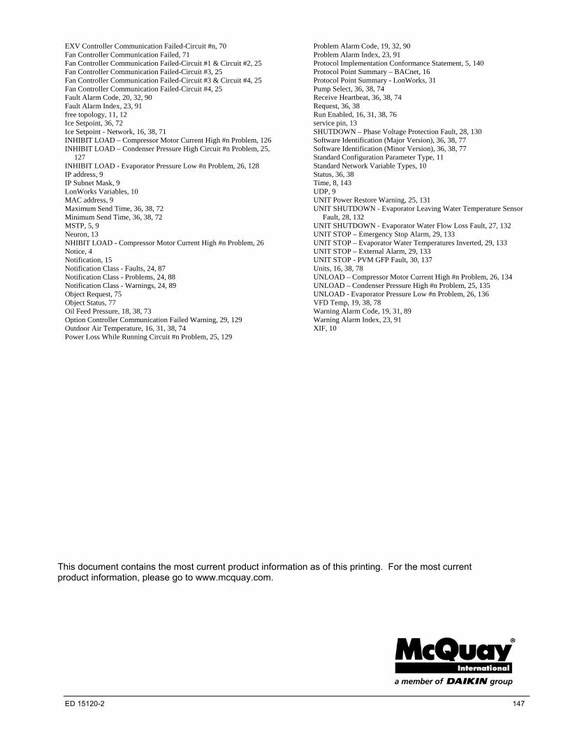
EXV Controller Communication Failed-Circuit #n, 70 Fan Controller Communication Failed, 71 Fan Controller Communication Failed-Circuit #1 & Circuit #2, 25 Fan Controller Communication Failed-Circuit #3, 25 Fan Controller Communication Failed-Circuit #3 & Circuit #4, 25 Fan Controller Communication Failed-Circuit #4, 25 Fault Alarm Code, 20, 32, 90 Fault Alarm Index, 23, 91 free topology, 11, 12 Ice Setpoint, 36, 72 Ice Setpoint - Network, 16, 38, 71 INHIBIT LOAD – Compressor Motor Current High #n Problem, 126 INHIBIT LOAD – Condenser Pressure High Circuit #n Problem, 25,
127 INHIBIT LOAD - Evaporator Pressure Low #n Problem, 26, 128 IP address, 9 IP Subnet Mask, 9 LonWorks Variables, 10 MAC address, 9 Maximum Send Time, 36, 38, 72 Minimum Send Time, 36, 38, 72 MSTP, 5, 9 Neuron, 13 NHIBIT LOAD - Compressor Motor Current High #n Problem, 26 Notice, 4 Notification, 15 Notification Class - Faults, 24, 87 Notification Class - Problems, 24, 88 Notification Class - Warnings, 24, 89 Object Request, 75 Object Status, 77 Oil Feed Pressure, 18, 38, 73 Option Controller Communication Failed Warning, 29, 129 Outdoor Air Temperature, 16, 31, 38, 74 Power Loss While Running Circuit #n Problem, 25, 129
Problem Alarm Code, 19, 32, 90 Problem Alarm Index, 23, 91 Protocol Implementation Conformance Statement, 5, 140 Protocol Point Summary – BACnet, 16 Protocol Point Summary - LonWorks, 31 Pump Select, 36, 38, 74 Receive Heartbeat, 36, 38, 74 Request, 36, 38 Run Enabled, 16, 31, 38, 76 service pin, 13 SHUTDOWN – Phase Voltage Protection Fault, 28, 130 Software Identification (Major Version), 36, 38, 77 Software Identification (Minor Version), 36, 38, 77 Standard Configuration Parameter Type, 11 Standard Network Variable Types, 10 Status, 36, 38 Time, 8, 143 UDP, 9 UNIT Power Restore Warning, 25, 131 UNIT SHUTDOWN - Evaporator Leaving Water Temperature Sensor
Fault, 28, 132 UNIT SHUTDOWN - Evaporator Water Flow Loss Fault, 27, 132 UNIT STOP – Emergency Stop Alarm, 29, 133 UNIT STOP – Evaporator Water Temperatures Inverted, 29, 133 UNIT STOP – External Alarm, 29, 133 UNIT STOP - PVM GFP Fault, 30, 137 Units, 16, 38, 78 UNLOAD – Compressor Motor Current High #n Problem, 26, 134 UNLOAD – Condenser Pressure High #n Problem, 25, 135 UNLOAD - Evaporator Pressure Low #n Problem, 26, 136 VFD Temp, 19, 38, 78 Warning Alarm Code, 19, 31, 89 Warning Alarm Index, 23, 91 XIF, 10
This document contains the most current product information as of this printing. For the most current product information, please go to www.mcquay.com.
ED 15120-2 147