mig29 twin68mm edf - hobbyking · pdf file1 mig29 twin68mm edf high performance fiberglass...
TRANSCRIPT
1
Mig29 Twin68mm EDF High performance Fiberglass Mig29 for twin 68mm electric ducted fan
Specifications are subject to change without notice
Warning !
This model is not a toy and please read the manual carefully before construction and
operating this model aircraft.
Specification
• Flying Weight 2,300-4,200 g
• Wing span 960mm.
• Length 1380mm.
• Rotor diameter 68mm

2
� Radio system for 4 channels or above
� 2x Electronic speed controllers for brushless motor
� 2x 70mm fan-units
� 2x 700W size brushless motors
� 4x Servo extension wires
� 2x Metal gear mini servo, for elevator
� 2x 9g servos for ailerons.
� 5 or 30 minute epoxy, CA Glue
� Velcro.
� Locktite/ threadlock
� Drill , drill bit 2mm, 3mm, 5mm
� Dremel tool
� Plier/cutter/ Philip screw driver
� 2mm , 3mm hex driver
� Scissor
Tools needed
Equipment and parts needed

3
Fuselage, Main wing, Exit ducting sheet, elevator , EDF cover, vertical fin, wing joiner,
landing gear and wheel, canopy, hardware bags ( screw, horn, linkage connector, M3 nut,
steering arm, 3mm collar, mounting plate, magnet).
Find a pre-cut slot at the underside of the wing and cut open the film. Insert the aileron servo
and pass the wire through the hole. You may use servo extension wire. CA the aileron to the
wing. Before gluing the aileron servo, center the servo horn by means of a servo tester or
Inside the Box
Aileron Servo

4
with a receiver/ transmitter. Install the servo with the balsa wood block provided. Mark the
horn insertion and cut a 5mm slot in the aileron and epoxy the control horn. Connect the
9.5cm linkage wire to the servo horn.
Do not glue the wing at this point. Try fitting the wings to the fuselage with the wing joiner.
The narrow end of the joiner goes into the wing. Adjust and orient the joiner such that both
wings are in perfect position. A 5mm hole can be drilled on the side to pass the wire of the
aileron servos. Drill two 3mm holes on the fuselage to connect the carbon rods, that
strengthen tensional force on the wing.
The wing joiner is made of fiberglass and this guarantee no risk of wing breakage at high
velocity. Sand the surface of the contact area to maximize bonding strength.
Glue the main wings with epoxy, tape or clamp the wings firmly to the fuselage. Support
the wing with blocks if necessary. Check for horizontal and longitudinal symmetry.
Main Wing
Main Wing
5
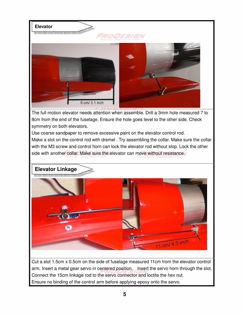
The full motion elevator needs attention when assemble. Drill a 3mm hole measured 7 to
8cm from the end of the fuselage. Ensure the hole goes level to the other side. Check
symmetry on both elevators.
Use coarse sandpaper to remove excessive paint on the elevator control rod.
Make a slot on the control rod with dremel . Try assembling the collar. Make sure the collar
with the M3 screw and control horn can lock the elevator rod without slop. Lock the other
side with another collar. Make sure the elevator can move without resistance.
Cut a slot 1.5cm x 0.5cm on the side of fuselage measured 11cm from the elevator control
arm. Insert a metal gear servo in centered position. Insert the servo horn through the slot.
Connect the 15cm linkage rod to the servo connector and loctite the hex nut.
Ensure no binding of the control arm before applying epoxy onto the servo.
Elevator Linkage
Elevator

6
Make the exit ducting with the temple provided. Cut the template and try fitting the EDF
unit. The calculate length is 20cm with exit area equals 85% of fan sweep area. Exit
diameter is 55mm. Adjust the exit diameter to your favor. Smaller exit diameter may
sacrifice thrust for terminal speed.
Glue both end of the EDF housing. This makes a perfect seal to enhance the EDF
efficiency. Assemble the ducted fan unit and anchor the ESC.
Check the inflow duct clearance. Test run the EDF and ensure air is blow backward. Check
for any excessive vibration.
Apply sufficient glue so that there is no air leakage.
Exit Ducting
Ducted Fan Unit

7
Drill holes and apply epoxy to the magnets in the canopy and the EDF compartment cover.
Apply epoxy and clamp the vertical fins. Ensure perfect vertical position of both fins.
Vertical Stabilizer
EDF cover

8
The pre-painted canopy and cockpit . Drill 4mm hole at front of the cockpit. Epoxy the 3cm FG
rod in the front. Glue the magnets to the canopy.
The neutral position of the elevator should be the same horizontal level with main wing.
The above photo shows the down elevator stick/ pitch up at low rate.
Elevator throws 14 mm up 14mm down. Use 50% exponential. Low rate 10mm.
Ailerons throws 14 mm up 14 mm down. Use 30% exponential. Low rate 10mm.
Control Throws
Cockpit

9
Main landing gear assembly. Assemble the pieces as above and apply sufficient epoxy. Insert
the wooden mount into the fuselage and note the direction of inclination as above. Apply
sufficient epoxy to make the block strongly attached to the fuselage. Attach the Landing gears.
Main Landing gear
10
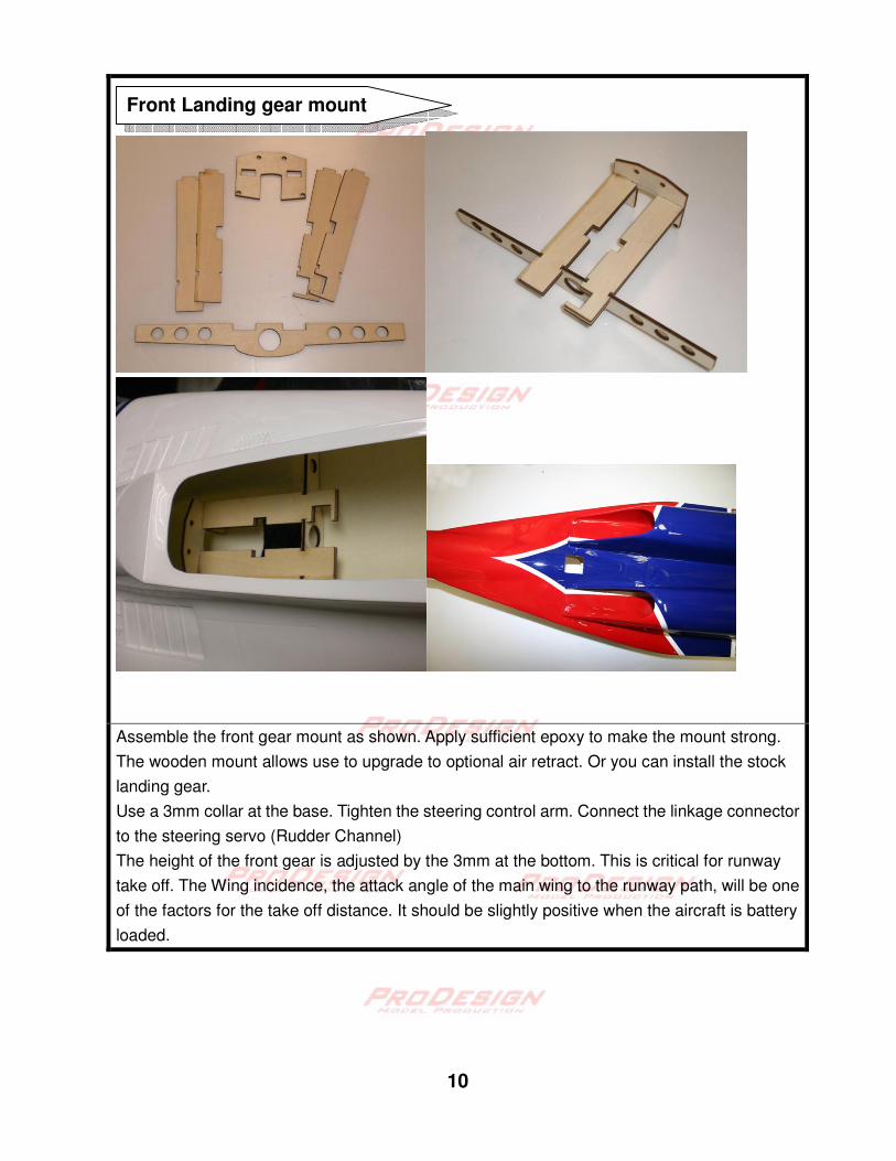
Assemble the front gear mount as shown. Apply sufficient epoxy to make the mount strong.
The wooden mount allows use to upgrade to optional air retract. Or you can install the stock
landing gear.
Use a 3mm collar at the base. Tighten the steering control arm. Connect the linkage connector
to the steering servo (Rudder Channel)
The height of the front gear is adjusted by the 3mm at the bottom. This is critical for runway
take off. The Wing incidence, the attack angle of the main wing to the runway path, will be one
of the factors for the take off distance. It should be slightly positive when the aircraft is battery
loaded.
Front Landing gear mount

11
The idea C.G. position is 10 cm behind the leading edge measured at where the wing meets
the fuselage. Adjust the battery position to obtain the correct C.G. Check the C.G. before flying.
C.G. setting
Nose gear steering

12
� Assistance from experienced pilot is necessary for beginners.
� Pre-flight adjustment and trimming must be done before flying. Check all
linkage, nuts, servo horns, linkage nuts and screws are tightened. Make sure
thread lockers are applied.
� Ensure the flying field is spacious and safe to fly.
� Bench test the electronic equipment on loading for 5minutes. Check
temperature of the ESC, BEC and battery. This is to ensure the power
system and the BEC are reliable. All EDF should be run in to test for
vibrations and loosen shaft.
� Check all electronic equipment. Range check the radio equipment. Test all
control surface are move in the assigned direction.
� Check battery voltage before use, even the battery are recently charged.
� At the first flight, it is prudent to check the C.G.
� In runway takeoff, slight finger pressure at the trailing edge of the elevator
should be able to pitch up the aircraft.
Enjoy!
Take pictures and video of your scale looking,
high performance ProDesign fighter!
Warning for pilot

13
Ducting Template