mikasa mt74
DESCRIPTION
mikasa ramm compactor mt-74fa robin gas engineTRANSCRIPT
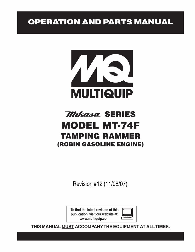
OPERATION AND PARTS MANUAL
Revision #12 (11/08/07)
SERIESMODEL MT-74FTAMPING RAMMER
(ROBIN GASOLINE ENGINE)
THIS MANUAL MUST ACCOMPANY THE EQUIPMENT AT ALL TIMES.
To find the latest revision of thispublication, visit our website at:
www.multiquip.com
PAGE 2 — MT-74F — OPERATION AND PARTS MANUAL — REV. #12 (11/08/07)
MT-74F — OPERATION AND PARTS MANUAL — REV. #12 (11/08/07) — PAGE 3
TABLE OF CONTENTS
Multiquip Tamping RammerMT-74FProposition 65 Warning ......................................... 2Table Of Contents ................................................. 3Parts Ordering Procedures ................................... 4Safety Message Alert Symbols ..........................5-6Rules For Safe Operation ..................................7-8Operation and Safety Decals ................................ 9General Information ............................................ 10Specifications ...................................................... 11Controls and Components .................................. 12Basic Engine ....................................................... 13Operation .......................................................14-16Maintenance ....................................................... 17Troubleshooting Guide ...................................18-19Explanation Of Codes In Remarks Column ........ 20Suggested Spare Parts ....................................... 21Name Plate and Decals .................................22-23Crankcase and Engine Assembly ..................24-27Guide Cylinder and Foot Assembly ...............28-29Tank and Handle Assembly ...........................30-33
ROBIN EH-12-2D46051 ENGINECrankcase and Cylinder Assembly ................34-35Crankshaft and Piston Assembly ...................36-37Muffler, Air Cleaner, Camshaft,& Carb. Assy. .38-39Governor Assembly .......................................40-41Recoil Starter and Blower Assembly .............42-43Magneto Assembly ........................................44-45Carburetor Assembly .....................................46-47
Terms and Condition Of Sale — Parts ................ 48
Specification and part number aresubject to change without notice.NOTE
PAGE 4 — MT-74F — OPERATION AND PARTS MANUAL — REV. #12 (11/08/07)
ww
w.m
ultiq
uip
.com
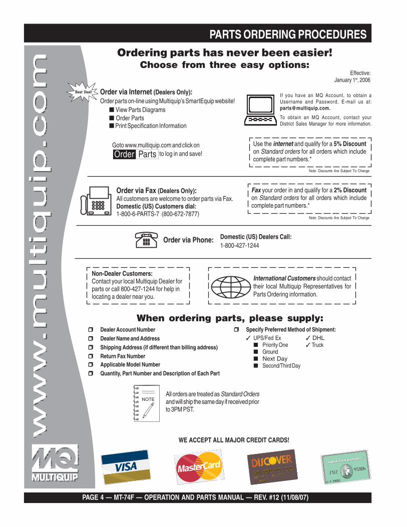
Ordering parts has never been easier!Choose from three easy options:
WE ACCEPT ALL MAJOR CREDIT CARDS!
When ordering parts, please supply:❒❒❒❒❒ Dealer Account Number
❒❒❒❒❒ Dealer Name and Address
❒❒❒❒❒ Shipping Address (if different than billing address)
❒❒❒❒❒ Return Fax Number❒❒❒❒❒ Applicable Model Number
❒❒❒❒❒ Quantity, Part Number and Description of Each Part
❒❒❒❒❒ Specify Preferred Method of Shipment:✓ UPS/Fed Ex ✓ DHL
■ Priority One ✓ Truck■ Ground■ Next Day■ Second/Third Day
All orders are treated as Standard Ordersand will ship the same day if received priorto 3PM PST.
If you have an MQ Account, to obtain aUsername and Password, E-mail us at:[email protected].
To obtain an MQ Account, contact yourDistrict Sales Manager for more information.
Order via Internet (Dealers Only):Order parts on-line using Multiquip’s SmartEquip website!
■ View Parts Diagrams■ Order Parts■ Print Specification Information
Note: Discounts Are Subject To Change
Goto www.multiquip.com and click on
Order Parts to log in and save!
Use the internet and qualify for a 5% Discounton Standard orders for all orders which includecomplete part numbers.*
Order via Fax (Dealers Only):All customers are welcome to order parts via Fax.Domestic (US) Customers dial:1-800-6-PARTS-7 (800-672-7877)
Fax your order in and qualify for a 2% Discounton Standard orders for all orders which includecomplete part numbers.*
Order via Phone: Domestic (US) Dealers Call:1-800-427-1244
Best Deal!
International Customers should contacttheir local Multiquip Representatives forParts Ordering information.
Non-Dealer Customers:Contact your local Multiquip Dealer forparts or call 800-427-1244 for help inlocating a dealer near you.
Note: Discounts Are Subject To Change
Effective:January 1st, 2006
PARTS ORDERING PROCEDURES
MT-74F — OPERATION AND PARTS MANUAL — REV. #12 (11/08/07) — PAGE 5
Safety precautions should be followedat all times when operating thisequipment. Failure to read andunderstand the Safety Messages andOperating Instructions could result ininjury to yourself and others.
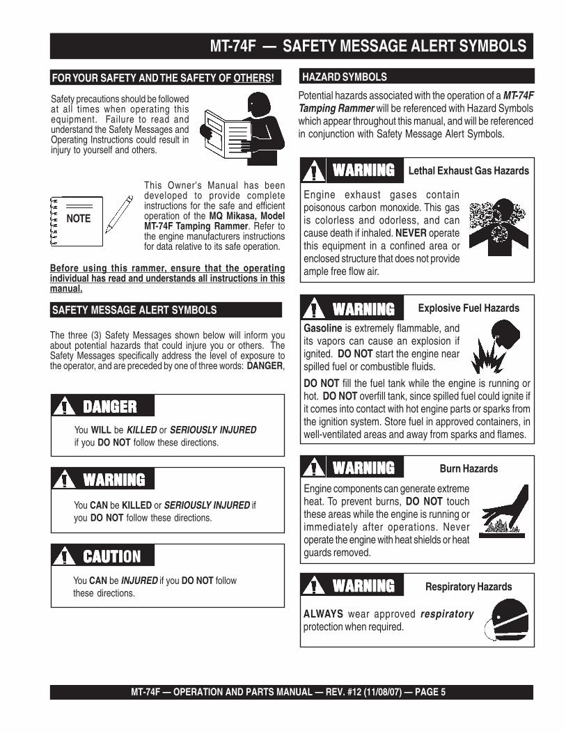
FOR YOUR SAFETY AND THE SAFETY OF OTHERS!
This Owner's Manual has beendeveloped to provide completeinstructions for the safe and efficientoperation of the MQ Mikasa, ModelMT-74F Tamping Rammer. Refer tothe engine manufacturers instructionsfor data relative to its safe operation.
SAFETY MESSAGE ALERT SYMBOLS
The three (3) Safety Messages shown below will inform youabout potential hazards that could injure you or others. TheSafety Messages specifically address the level of exposure tothe operator, and are preceded by one of three words: DANGER,
MT-74F — SAFETY MESSAGE ALERT SYMBOLS
NOTE
You WILL be KILLED or SERIOUSLY INJUREDif you DO NOT follow these directions.
You CAN be KILLED or SERIOUSLY INJURED ifyou DO NOT follow these directions.
You CAN be INJURED if you DO NOT followthese directions.
CAUTICAUTICAUTICAUTICAUTION
DANGERDANGERDANGERDANGERDANGER
WARNINGWARNINGWARNINGWARNINGWARNING
Lethal Exhaust Gases
HAZARD SYMBOLS
Potential hazards associated with the operation of a MT-74FTamping Rammer will be referenced with Hazard Symbolswhich appear throughout this manual, and will be referencedin conjunction with Safety Message Alert Symbols.
Engine exhaust gases containpoisonous carbon monoxide. This gasis colorless and odorless, and cancause death if inhaled. NEVER operatethis equipment in a confined area orenclosed structure that does not provideample free flow air.
Gasoline is extremely flammable, andits vapors can cause an explosion ifignited. DO NOT start the engine nearspilled fuel or combustible fluids.
DO NOT fill the fuel tank while the engine is running orhot. DO NOT overfill tank, since spilled fuel could ignite ifit comes into contact with hot engine parts or sparks fromthe ignition system. Store fuel in approved containers, inwell-ventilated areas and away from sparks and flames.
Engine components can generate extremeheat. To prevent burns, DO NOT touchthese areas while the engine is running orimmediately after operations. Neveroperate the engine with heat shields or heatguards removed.
ALWAYS wear approved respiratoryprotection when required.
Lethal Exhaust Gas HazardsWARNINGWARNINGWARNINGWARNINGWARNING
Explosive Fuel HazardsWARNINGWARNINGWARNINGWARNINGWARNING
Burn HazardsWARNINGWARNINGWARNINGWARNINGWARNING
Respiratory HazardsWARNINGWARNINGWARNINGWARNINGWARNING
Before using this rammer, ensure that the operatingindividual has read and understands all instructions in thismanual.
PAGE 6 — MT-74F — OPERATION AND PARTS MANUAL — REV. #12 (11/08/07)
MT-74F — SAFETY MESSAGE ALERT SYMBOLS
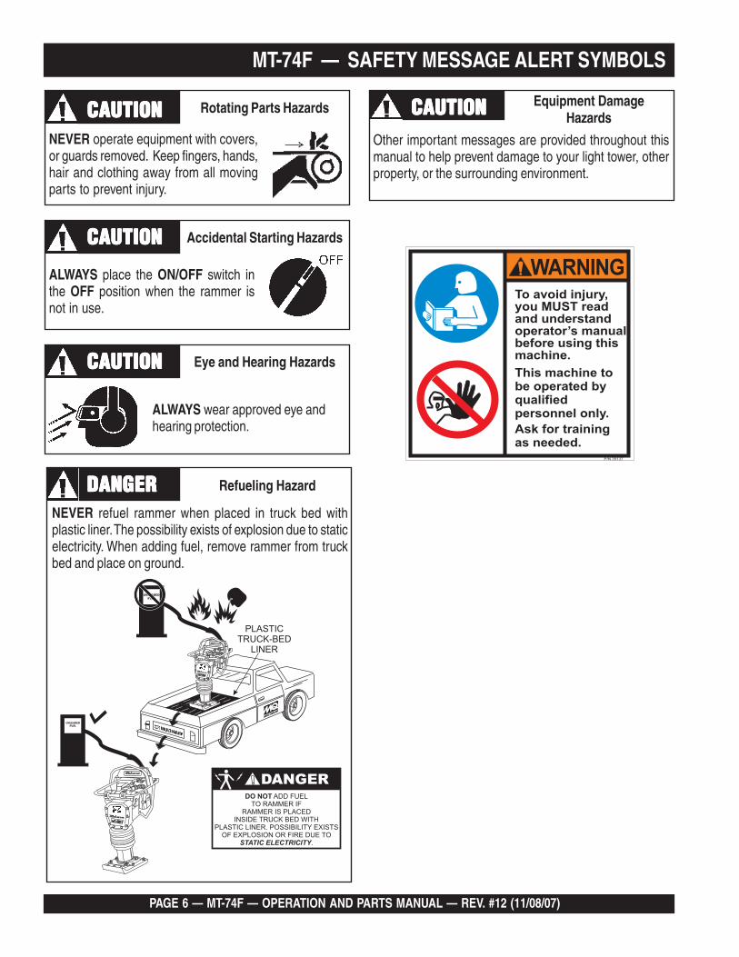
ALWAYS place the ON/OFF switch inthe OFF position when the rammer isnot in use.
ALWAYS wear approved eye andhearing protection.
NEVER operate equipment with covers,or guards removed. Keep fingers, hands,hair and clothing away from all movingparts to prevent injury.
Rotating Parts HazardsCAUTIONCAUTIONCAUTIONCAUTIONCAUTION
Accidental Starting HazardsCAUTIONCAUTIONCAUTIONCAUTIONCAUTION
Eye and Hearing HazardsCAUTIONCAUTIONCAUTIONCAUTIONCAUTION
Other important messages are provided throughout thismanual to help prevent damage to your light tower, otherproperty, or the surrounding environment.
Equipment DamageHazardsCAUTIONCAUTIONCAUTIONCAUTIONCAUTION
NEVER refuel rammer when placed in truck bed withplastic liner. The possibility exists of explosion due to staticelectricity. When adding fuel, remove rammer from truckbed and place on ground.
Refueling HazardDANGERDANGERDANGERDANGERDANGER
MT-74F — OPERATION AND PARTS MANUAL — REV. #12 (11/08/07) — PAGE 7
The following safety guidelines should always be used whenoperating the MT-74F Tamping Rammer:
GENERAL SAFETY
■ DO NOT operate or service thisequipment before reading this entiremanual.
■ This equipment should not be operated by persons under18 years of age.
■ NEVER operate this equipment without proper protectiveclothing, shatterproof glasses, steel-toed boots and otherprotective devices required by the job.
■ High Temperatures – Allow the engine to cool beforeadding fuel or performing service and maintenancefunctions. Contact with hot! components can cause seriousburns.
■ The engine section of this rammer requires an adequatefree flow of cooling air. NEVER operate the rammer inany enclosed or narrowarea where free flow of theair is restricted. If the airflow is restricted it willcause serious damage tothe rammer or engine andmay cause injury to people.Remember the rammer'sengine gives off DEADLYcarbon monoxide gas.
■ ALWAYS refuel in a well-ventilated area, away fromsparks and open flames.
■ ALWAYS use extreme caution when working withflammable liquids. When refueling, stop the engine andallow it to cool. DO NOT smoke aroundor near the machine. Fire or explosioncould result from fuel vapors, or if fuelis spilled on a hot engine.
■ NEVER operate the rammer in anexplosive atmosphere or nearcombustible materials. An explosion or fire could resultcausing severe bodily harm or even death.
DANGERDANGERDANGERDANGERDANGERFailure to follow instructions in this manual may leadto serious injury or even death! This equipment is tobe operated by trained and qualified personnel only!This equipment is for industrial use only.
■ NEVER operate this equipment under the influence ofdrugs or alcohol.
Read this manual! ■ NEVER touch the hot exhaustmanifold, muffler or cylinder. Allowthese parts to cool before servicingengine or rammer.
■ ALWAYS wear proper respiratory (mask),hearing and eye protection equipment whenoperating the rammer.
■ Whenever necessary, replace nameplate, operation andsafety decals when they become difficult read.
■ Manufacturer does not assume responsibility for anyaccident due to equipment modifications.
■ NEVER use accessories or attachments, which are notrecommended by Multiquip for this equipment. Damageto the equipment and/or injury to user may result.
■ NEVER operate this equipment when notfeeling well due to fatigue, illness or takingmedicine.
MT-74F — RULES FOR SAFE OPERATION
■ Topping-off to filler port is dangerous, as it tends to spillfuel.
■ Stop the engine when leaving the rammer unattended.■ Maintain this equipment in a safe operating condition at
all times.
■ DO NOT smoke around or near themachine. Fire or explosion could resultfrom fuel vapors, or if fuel is spilled on ahot engine.
PAGE 8 — MT-74F — OPERATION AND PARTS MANUAL — REV. #12 (11/08/07)
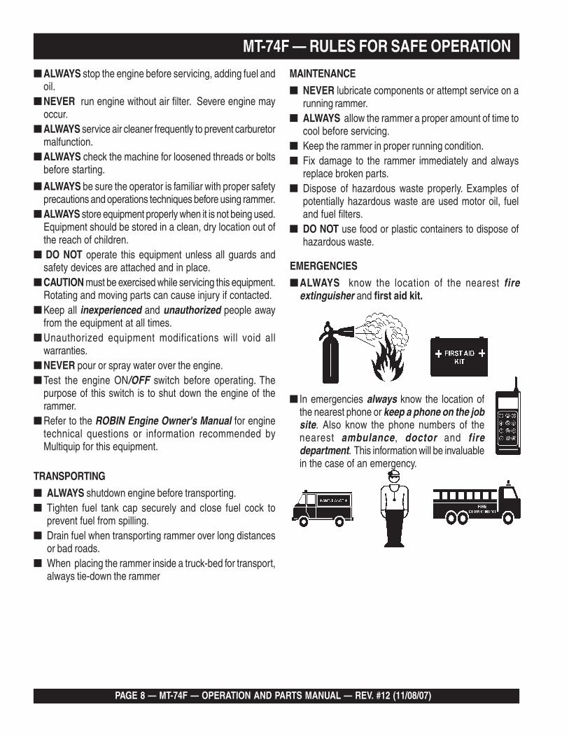
■ ALWAYS stop the engine before servicing, adding fuel andoil.
■ NEVER run engine without air filter. Severe engine mayoccur.
■ ALWAYS service air cleaner frequently to prevent carburetormalfunction.
■ ALWAYS check the machine for loosened threads or boltsbefore starting.
■ ALWAYS be sure the operator is familiar with proper safetyprecautions and operations techniques before using rammer.
■ ALWAYS store equipment properly when it is not being used.Equipment should be stored in a clean, dry location out ofthe reach of children.
■ DO NOT operate this equipment unless all guards andsafety devices are attached and in place.
■ CAUTION must be exercised while servicing this equipment.Rotating and moving parts can cause injury if contacted.
■ Keep all inexperienced and unauthorized people awayfrom the equipment at all times.
■ Unauthorized equipment modifications will void allwarranties.
■ NEVER pour or spray water over the engine.■ Test the engine ON/OFF switch before operating. The
purpose of this switch is to shut down the engine of therammer.
■ Refer to the ROBIN Engine Owner's Manual for enginetechnical questions or information recommended byMultiquip for this equipment.
TRANSPORTING
■ ALWAYS shutdown engine before transporting.■ Tighten fuel tank cap securely and close fuel cock to
prevent fuel from spilling.■ Drain fuel when transporting rammer over long distances
or bad roads.■ When placing the rammer inside a truck-bed for transport,
always tie-down the rammer
MAINTENANCE
■ NEVER lubricate components or attempt service on arunning rammer.
■ ALWAYS allow the rammer a proper amount of time tocool before servicing.
■ Keep the rammer in proper running condition.■ Fix damage to the rammer immediately and always
replace broken parts.■ Dispose of hazardous waste properly. Examples of
potentially hazardous waste are used motor oil, fueland fuel filters.
■ DO NOT use food or plastic containers to dispose ofhazardous waste.
MT-74F — RULES FOR SAFE OPERATION
■ In emergencies always know the location ofthe nearest phone or keep a phone on the jobsite. Also know the phone numbers of thenearest ambulance, doctor and firedepartment. This information will be invaluablein the case of an emergency.
EMERGENCIES
■ ALWAYS know the location of the nearest fireextinguisher and first aid kit.
MT-74F — OPERATION AND PARTS MANUAL — REV. #12 (11/08/07) — PAGE 9
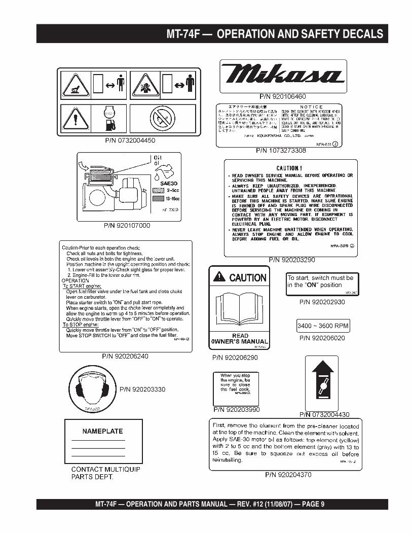
MT-74F — OPERATION AND SAFETY DECALS
PAGE 10 — MT-74F — OPERATION AND PARTS MANUAL — REV. #12 (11/08/07)
Definition of Tamping Rammer
The Mikasa MT-74F tamping rammer is a powerful compactingtool capable of applying a tremendous force in consecutiveimpacts to a soil surface. Its applications include soil compactingfor road, embankments and reservoirs as well as backfilling forgas pipelines, water pipelines and cable installation work.
The impact force of the MT-74F levels and uniformly compactsvoids between soil particles to increase dry density.
Circular motion is converted to create impact force. The MT-74Ftamping rammer develops a powerful compacting force at thefoot of the rammer. To maintain optimum performance, properoperation and service are essential.
Construction of Tamping Rammer
The Mikasa MT-74F is equipped with an air cooled, four-cyclegasoline engine. Transmission of the power takes place byincreasing the engine speed to engage the centrifugal clutch.
Rammer Gearbox and Spring Cylinder
The Mikasa MT-74F uses an oil bath lubrication system. Alwayscheck the oil level through the oil level sight glass at the rear ofthe tamper foot.
Controls
Before starting the MT-74F Tamping Rammer identify andunderstand the function of the controls. See Figure 1.
MT-74F — GENERAL INFORMATION
MT-74F — OPERATION AND PARTS MANUAL — REV. #12 (11/08/07) — PAGE 11
MT-74F — SPECIFICATIONS
snoitacificepSremmaRF47-TM.1elbaT snoitacificepSremmaRF47-TM.1elbaT snoitacificepSremmaRF47-TM.1elbaT snoitacificepSremmaRF47-TM.1elbaT snoitacificepSremmaRF47-TM.1elbaT
LEDOM F47-TM
thgieHllarevO )mm340,1(.ni1.14
htdiWllarevO )mm214(ni2.61
htgneLrevO )mm027(ni3.82
eziSeohS )mm882(.ni3.11
etunim/swolB 086
ecroFtcapmI )wolb/gk004,1(wolb/.sbl001,3
hctulC lagufirtneCcitamotuA
thgieWgnitarepO )gk37(.sbl161
snoitacificepSenignE15064D2-21HE.2elbaT snoitacificepSenignE15064D2-21HE.2elbaT snoitacificepSenignE15064D2-21HE.2elbaT snoitacificepSenignE15064D2-21HE.2elbaT snoitacificepSenignE15064D2-21HE.2elbaT
LEDOM ENIGNE15064D2-21HENIBOR
epyT enignEenilosaGekortS4delooC-riA
tnemecalpsiDnotsiP )3mc121(.ni.uc83.7
tuptuO.xaM ph0.4
daoLoN,deepSdenrevoG.xaM mpr000,4
metsySgnilooC delooC-riA
metsySnoitacirbuL liOrotoM03W01---htaBliO
leuF enilosagdedaelnU
metsySgnitratS retratSlioceR
Specifications are general and are subject to change without notice. If exactmeasurements are required, equipment should be weighed and measured.
NOTE
PAGE 12 — MT-74F — OPERATION AND PARTS MANUAL — REV. #12 (11/08/07)
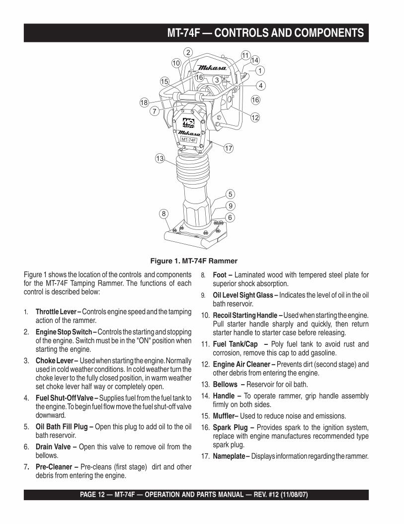
Figure 1 shows the location of the controls and componentsfor the MT-74F Tamping Rammer. The functions of eachcontrol is described below:
L1. A Returned Material Authorization must be approved by Multiquip prior to shipment. A copy of the Authorization mustaccompany the shipment to the designated Warehouse. A copy of the original Multiquip invoice to the customer mustalso accompany the shipment.
1. Throttle Lever – Controls engine speed and the tampingaction of the rammer.
2. Engine Stop Switch – Controls the starting and stoppingof the engine. Switch must be in the "ON" position whenstarting the engine.
3. Choke Lever – Used when starting the engine. Normallyused in cold weather conditions. In cold weather turn thechoke lever to the fully closed position, in warm weatherset choke lever half way or completely open.
4. Fuel Shut-Off Valve – Supplies fuel from the fuel tank tothe engine. To begin fuel flow move the fuel shut-off valvedownward.
5. Oil Bath Fill Plug – Open this plug to add oil to the oilbath reservoir.
6. Drain Valve – Open this valve to remove oil from thebellows.
7. Pre-Cleaner – Pre-cleans (first stage) dirt and otherdebris from entering the engine.
8. Foot – Laminated wood with tempered steel plate forsuperior shock absorption.
9. Oil Level Sight Glass – Indicates the level of oil in the oilbath reservoir.
10. Recoil Starting Handle – Used when starting the engine.Pull starter handle sharply and quickly, then returnstarter handle to starter case before releasing.
11. Fuel Tank/Cap – Poly fuel tank to avoid rust andcorrosion, remove this cap to add gasoline.
12. Engine Air Cleaner – Prevents dirt (second stage) andother debris from entering the engine.
13. Bellows – Reservoir for oil bath.
14. Handle – To operate rammer, grip handle assemblyfirmly on both sides.
15. Muffler– Used to reduce noise and emissions.16. Spark Plug – Provides spark to the ignition system,
replace with engine manufactures recommended typespark plug.
17. Nameplate – Displays information regarding the rammer.
Figure 1. MT-74F Rammer
MT-74F — CONTROLS AND COMPONENTS
MT-74F — OPERATION AND PARTS MANUAL — REV. #12 (11/08/07) — PAGE 13
MT-74F — BASIC ENGINE
WARNINGWARNING
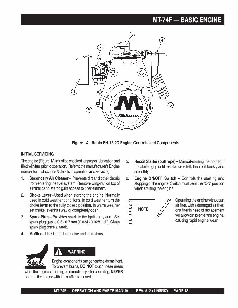
Figure 1A. Robin EH-12-2D Engine Controls and Components
INITIAL SERVICING
The engine (Figure 1A) must be checked for proper lubrication andfilled with fuel prior to operation. Refer to the manufacturer's Enginemanual for instructions & details of operation and servicing.
1. Secondary Air Cleaner – Prevents dirt and other debrisfrom entering the fuel system. Remove wing-nut on top ofair filter cannister to gain access to filter element.
2. Choke Lever –Used when starting the engine. Normallyused in cold weather conditions. In cold weather turn thechoke lever to the fully closed position, in warm weatherset choke lever half way or completely open.
3. Spark Plug – Provides spark to the ignition system. Setspark plug gap to 0.6 - 0.7 mm (0.024 - 0.028 inch). Cleanspark plug once a week.
4. Muffler – Used to reduce noise and emissions.
Operating the engine without anair filter, with a damaged air filter,or a filter in need of replacementwill allow dirt to enter the engine,causing rapid engine wear.
5. Recoil Starter (pull rope) – Manual-starting method. Pullthe starter grip until resistance is felt, then pull briskly andsmoothly.
6. Engine ON/OFF Switch – Controls the starting andstopping of the engine. Switch must be in the "ON" positionwhen starting the engine.
NOTE
WARNING
Engine components can generate extreme heat.To prevent burns, DO NOT touch these areas
while the engine is running or immediately after operating. NEVERoperate the engine with the muffler removed.
PAGE 14 — MT-74F — OPERATION AND PARTS MANUAL — REV. #12 (11/08/07)
Rammer Gearbox and Spring Cylinder Oil Bath
This unit uses an oil bath lubrication system. Perform the following:
1. Check the oil level through the oil level sight glass (Figure 2)at the rear of the tamper foot.
This section is intended to assist the operator with the initialstart-up of the MT-74F Tamping Rammer. It extremely importantthat this section be read carefully before attempting to operatethe rammer.
DO NOT use your rammer until this section is thoroughlyunderstood.
The oil level should be kept at the halfway point of the sight glass.
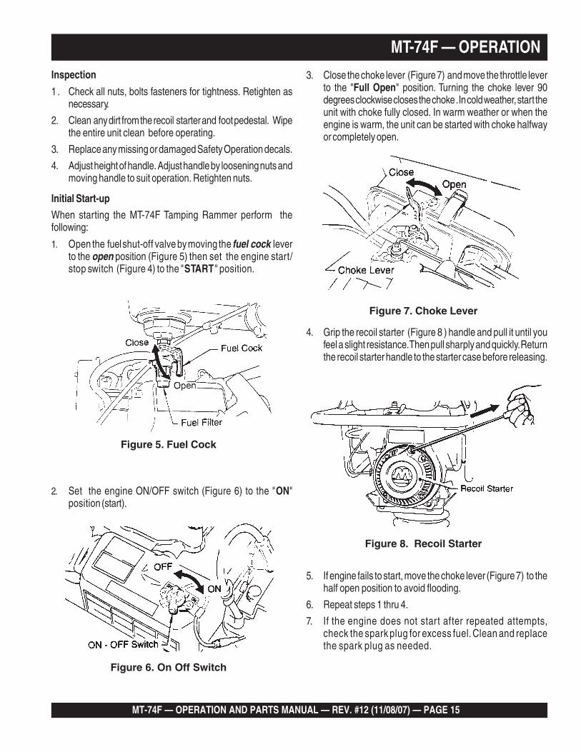
2. Low levels of oil may result in engine seizure due to highlevels of consumption during operations.
3. Check the engine oil level and if the engine oil level is low, it should be refilled. Use the proper motor oil as suggested in
the Table 3 below.
Figure 4. Engine Oil Dipstick
Figure 2. Foot Housing Sight Glass
2. If oil is not visible, add 10W-30 motor oil into the oil fill plugopening (Figure 2). The bath contains approximately 1.7pints (800 cc.)
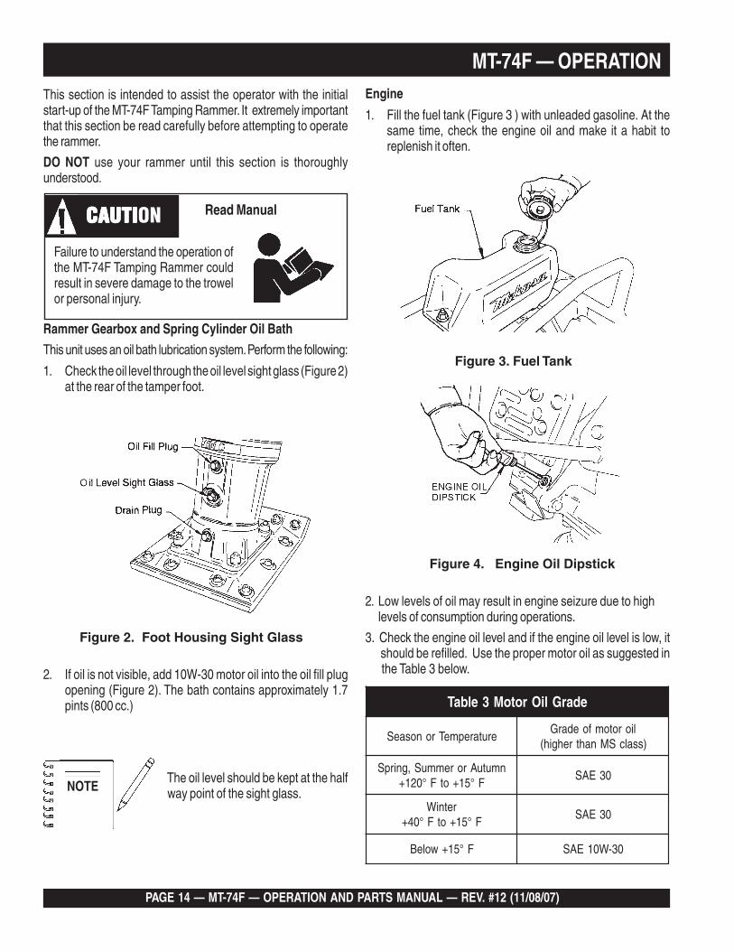
Figure 3. Fuel Tank
Engine
1. Fill the fuel tank (Figure 3 ) with unleaded gasoline. At thesame time, check the engine oil and make it a habit toreplenish it often.
MT-74F — OPERATION
edarGliOrotoM3elbaT
erutarepmeTronosaeSliorotomfoedarG
)ssalcSMnahtrehgih(
nmutuAroremmuS,gnirpSF°51+otF°021+
03EAS
retniWF°51+otF°04+
03EAS
F°51+woleB 03-W01EAS
NOTE
Failure to understand the operation ofthe MT-74F Tamping Rammer couldresult in severe damage to the trowelor personal injury.
CAUTICAUTICAUTICAUTICAUTION Read Manual
MT-74F — OPERATION AND PARTS MANUAL — REV. #12 (11/08/07) — PAGE 15
MT-74F — OPERATION
Inspection
1. Check all nuts, bolts fasteners for tightness. Retighten asnecessary.
2. Clean any dirt from the recoil starter and foot pedestal. Wipethe entire unit clean before operating.
3. Replace any missing or damaged Safety Operation decals.
4. Adjust height of handle. Adjust handle by loosening nuts andmoving handle to suit operation. Retighten nuts.
Initial Start-up
When starting the MT-74F Tamping Rammer perform thefollowing:
1. Open the fuel shut-off valve by moving the fuel cock leverto the open position (Figure 5) then set the engine start/stop switch (Figure 4) to the "START" position.
3. Close the choke lever (Figure 7) and move the throttle leverto the "Full Open" position. Turning the choke lever 90degrees clockwise closes the choke . In cold weather, start theunit with choke fully closed. In warm weather or when theengine is warm, the unit can be started with choke halfwayor completely open.
Figure 6. On Off Switch
Figure 5. Fuel Cock
2. Set the engine ON/OFF switch (Figure 6) to the "ON"position (start).
Figure 7. Choke Lever
4. Grip the recoil starter (Figure 8 ) handle and pull it until youfeel a slight resistance. Then pull sharply and quickly. Returnthe recoil starter handle to the starter case before releasing.
5. If engine fails to start, move the choke lever (Figure 7) to thehalf open position to avoid flooding.
6. Repeat steps 1 thru 4.
7. If the engine does not start after repeated attempts,check the spark plug for excess fuel. Clean and replacethe spark plug as needed.
Figure 8. Recoil Starter
PAGE 16 — MT-74F — OPERATION AND PARTS MANUAL — REV. #12 (11/08/07)
Operation
1. To start the rammer tamping action, move the throttle lever(Figure 9) quickly from IDLE (close) to the FULL OPENposition . DO NOT move the throttle lever slowly as this maycause damage to the clutch or spring.
3. To stop the tamping action, move throttle lever quickly fromthe FULL OPEN to IDLE position.
Stopping The Engine
Normal Shutdown1. Move throttle lever quickly from the FULL OPEN to IDLE
position (Figure 10) and run the engine for three minutes atlow speed. After the engine cools, turn the engine start/stopswitch to the “STOP” position (Figure 6) until engine comesto a complete stop.
2. Close the fuel shut- off valve by moving the fuel cock lever tothe CLOSED position. See Figure 5.
Emergency Showdown
1. Move the throttle lever quickly to the IDLE position, and turnthe engine start/stop switch to the STOP position.
Figure 10. Throttle Lever (Idle)
MT-74F — OPERATION
CAUTION:CAUTION:CAUTION:CAUTION:CAUTION:Make sure that the throttle lever is moved to theFULL OPEN position. Operating the rammer atless than full speeds can result in damage tothe clutch springs or foot
2. The MT-74F Tamping rammer is designed to run at 4,000 rpm.At optimum rpm the foot hits at the rate of 680 impacts perminute. Increasing throttle speed past factory set rpm doesnot increase impacts and may damage unit. The MT-74F isdesigned to advance while tamping. For faster advance, pullback slightly on the handle so that rear of foot contacts soilfirst.
Figure 9. Throttle Lever (Full Open)
MT-74F — OPERATION AND PARTS MANUAL — REV. #12 (11/08/07) — PAGE 17
Maintenance
Perform the scheduled maintenance procedures as indicated:
DAILY
■ Thoroughly remove dirt and oil from the engine and controlarea. Clean or replace the air cleaner elements as necessary.Check and retighten all fasteners as necessary. Check thespring box and bellows for oil leaks. Repair or replace asneeded.
WEEKLY
■ Remove the fuel filter cap and clean the inside of the fueltank.
■ Remove or clean the filter at the bottom of the tank.
■ Remove and clean the spark plug, then adjust the spark gapto 0.02~0.03 inch (0.6~0.7 mm). This unit has electronicignition, which requires no adjustments.
■ Clean air cleaner cover.
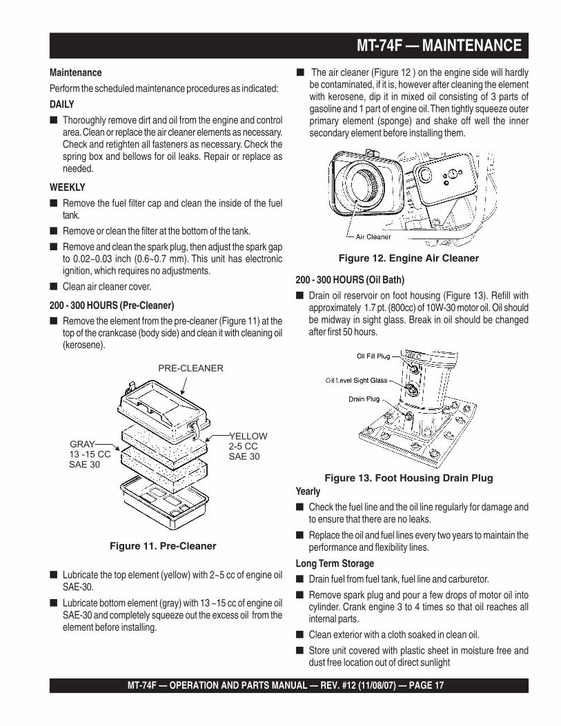
200 - 300 HOURS (Pre-Cleaner)■ Remove the element from the pre-cleaner (Figure 11) at the
top of the crankcase (body side) and clean it with cleaning oil(kerosene).
MT-74F — MAINTENANCE
Figure 11. Pre-Cleaner
■ Lubricate the top element (yellow) with 2~5 cc of engine oilSAE-30.
■ Lubricate bottom element (gray) with 13 ~15 cc of engine oilSAE-30 and completely squeeze out the excess oil from theelement before installing.
200 - 300 HOURS (Oil Bath)■ Drain oil reservoir on foot housing (Figure 13). Refill with
approximately 1.7 pt. (800cc) of 10W-30 motor oil. Oil shouldbe midway in sight glass. Break in oil should be changedafter first 50 hours.
■ The air cleaner (Figure 12 ) on the engine side will hardlybe contaminated, if it is, however after cleaning the elementwith kerosene, dip it in mixed oil consisting of 3 parts ofgasoline and 1 part of engine oil. Then tightly squeeze outerprimary element (sponge) and shake off well the innersecondary element before installing them.
Figure 12. Engine Air Cleaner
Yearly■ Check the fuel line and the oil line regularly for damage and
to ensure that there are no leaks.
■ Replace the oil and fuel lines every two years to maintain theperformance and flexibility lines.
Long Term Storage■ Drain fuel from fuel tank, fuel line and carburetor.
■ Remove spark plug and pour a few drops of motor oil intocylinder. Crank engine 3 to 4 times so that oil reaches allinternal parts.
■ Clean exterior with a cloth soaked in clean oil.
■ Store unit covered with plastic sheet in moisture free anddust free location out of direct sunlight
Figure 13. Foot Housing Drain Plug
YELLOWGRAY
13 -15 CC
SAE 30
2-5 CC
SAE 30
PRE-CLEANER
PAGE 18 — MT-74F — OPERATION AND PARTS MANUAL — REV. #12 (11/08/07)
MT-74F — TROUBLESHOOTING GUIDE
GNITOOHSELBUORTENIGNE.4ELBAT
MOTPMYS MELBORPELBISSOP NOITULOS
tratsottluciffiD
gulpkrapstubelbaliavasileuFelbaliavarewoP(.etingitonlliw
.)elbacnoisnethgihta
?egdirbgniebgulpnoitingI .metsysnoitingikcehC
?noitingitatisopednobraC .noitingiecalperronaelC
evitcefedoteudtiucrictrohS?srotalusni
.srotalusniecalpeR
?pagkrapsreporpmI .pagtcerrocehtotpaggulpkrapsteS
gulpkrapstubelbaliavasileuFrewoP(.etingitonlliw TON
.)elbacnoisnethgihtaelbaliava
?hctiwspotstatiucrictrohS .evitcefedfihctiwspotsecalpeR.tiucrichctiwspotskcehC
?evitcefedliocnoitingI .liocnoitingiecalpeR
gulpkrapsdnaelbaliavasileuFnoisserpmoc(setingi )lamron .
nobrachtiwdeggolcrelffuM?stisoped
.relffumecalperronaelC
,retaw(etauqedaniesunileuF?)tsud
.leufhserfhtiwecalperdnametysleufhsulF
?deggolcrenaelCriA .renaelcriaecalperronaelC
gulpkrapsdnaelbaliavasileuFnoisserpmoc(setingi wol .)
?teksagdaehrednilycevitcefeD .teksagdaehecalperrostlobdaehrednilycnethgiT
?nrowrednilyC .rednilycecalpeR
?esoolgulpkrapS .gulpkrapsnehgiT
yrotcafsitastonnoitarepO
elbaliavarewophguonetoN-ssimon,lamronnoisserpmoc(
.)gnirif
?deggolcrenaelcriA .renaelcriaecalperronaelC
?enilleufniriA .enilleufmorf)riaevomer(deelB
taolfroterubracnilevelleuF?reporpmirebmahc .taolfroterubractsujdA
?rednilycnistisopednobraC .rednilycecalperronaelC
elbaliavarewophguonetoN-ssim,lamronnoisserpmoc(
.)gnirif
?evitcefedliocnoitingI .leufhserfhtiwecalperdnametysleufhsulF
?strohsnetfogulpnoitingI .noitinginaelc,seriwnoitingiecalpeR
,retaw(etauqedaniesunileuF?)tsud
.leufhserfhtiwecalperdnametysleufhsulF
.staehrevoenignE
ninoitsopednobracevissecxE?rebmahcnoitsubmoc
.esacknarcecalperronaelC
htiwdeggolcrelffumrotsuahxE.nobrac
.relffumecalperronaelC
?tcerrocnieulavtaehgulpkrapS .gulpkrapsepyttcerrochtiwgulpkrapsecalpeR
MT-74F — OPERATION AND PARTS MANUAL — REV. #12 (11/08/07) — PAGE 19
MT-74F — TROUBLESHOOTING GUIDE
ENGINEENGINEENGINEENGINEENGINE )deunitnoc(GNITOOHSELBUORTENIGNE.4ELBAT
MOTPMYS MELBORPELBISSOP NOITULOS
yrotcafsitastonnoitarepO
.setautculfdeepslanoitatoR
?reporpmitnemtsujdaronrevoG .reveltcerrocotronrevogtsujdA
?evitcefedgnirpsronrevoG .noitingiecalperronaelC
?citarrewolfleuF .enilleufkcehC
noitcushguorhtninekatriA?enil .enilnoitcuskcehC
gnikrowtonretratslioceR.ylreporp
?trapgnitatornitsuD .ylbmessaretratsliocernaelC
?eruliafgnirpslaripS .gnirpslaripsecalpeR
GNITOOHSELBUORTREMMAR.5ELBAT
MOTPMYS MELBORPELBISSOP NOITULOS
ediutilpmatubsetatorenignE.ekirtstonseodromrofinuton
revelelttorhtfodeepsgnitarepO?tesyltcerrocnisi
.noitisoptcerrocotrevelelttorhtteS
?ssecxeniliO .leveltcerrocotgnirB.liossecxeniarD
?spilshctulC .hctulctsujdaroecalpeR
?eruliaFgnirpS .gnirpslaripsecalpeR
?reporpmienignefodeepS .gnittesMPRgnitarepotcerrocotdeepsenignetsujdA
PAGE 20 — MT-74F — OPERATION AND PARTS MANUAL — REV. #12 (11/08/07)
MT-74F — EXPLANATION OF PARTS SECTION REMARKS COLUMN
The contents and part numbers listed in the parts section aresubject to change without notice. Multiquip does notguarantee the availibility of the parts listed.
When ordering a part that has more than oneitem number listed, check the remarks columnfor help in determining the proper part to order.
The following section explains the different symbols andremarks used in the Parts section of this manual. Use the helpnumbers found on the back page of the manual if there are anyquestions.
NO. Column
Unique Symbols - All items with same unique symbol(*, #, +, %, or >) in the number column belong to the sameassembly or kit, which is indicated by a note in the “Remarks”column.
Duplicate Item Numbers - Duplicate numbers indicatemultiple part numbers are in effect for the same generalitem, such as different size saw blade guards in use or apart that has been updated on newer versions of the samemachine.
Sample Parts List:NO. PART NO. PART NAME QTY. REMARKS1 12345 BOLT ...................... 1 ...... INCLUDES ITEMS W/*2* WASHER, 1/4 IN. .............NOT SOLD SEPARATELY2* 12347 WASHER, 3/8 IN. ... 1 ......MQ-45T ONLY3 12348 HOSE ................... A/R ....MAKE LOCALLY4 12349 BEARING ............... 1 ......S/N 2345B AND ABOVE
PART NO. Column
Numbers Used - Part numbers can be indicated by anumber, a blank entry, or TBD.
TBD (To Be Determined) is generally used to show a partthat has not been assigned a formal part number at time ofpublication.
A blank entry generally indicates that the item is not soldseparately or is not sold by Multiquip. Other entries will beclarified in the “Remarks” Column.
QTY. Column
Numbers Used - Item quantity can be indicated by anumber, a blank entry, or A/R.
A/R (As Required) is generally used for hoses or other partsthat are sold in bulk and cut to length.
A blank entry generally indicates that the item is not soldseparately. Other entries will be clarified in the “Remarks”Column.
REMARKS Column
Some of the most common notes found in the “Remarks”Column are listed below. Other additional notes needed todescribe the item can also be shown.
Assembly/Kit - All items on the parts list with the sameunique symbol will be included when this item is purchased.
Indicated by:“INCLUDES ITEMS W/(unique symbol)”
Serial Number Break - Used to list an effective serialnumber range where a particular part is used.
Indicated by:“S/N XXXXX AND BELOW”“S/N XXXX AND ABOVE”“S/N XXXX TO S/N XXX”
Specific Model Number Use - Indicates that the part isused only with the specific model number or model numbervariant listed. It can also be used to show a part is NOTused on a specific model or model number variant.
Indicated by:“XXXXX ONLY”“NOT USED ON XXXX”
“Make/Obtain Locally” - Indicates that the part can bepurchased at any hardware shop or made out of availableitems. Examples include battery cables, shims, and certainwashers and nuts.
“Not Sold Separately” - Indicates that an item cannot bepurchased as a separate item and is either part of anassembly/kit that can be purchased, or is not available forsale through Multiquip.
MT-74F — OPERATION AND PARTS MANUAL — REV. #12 (11/08/07) — PAGE 21
MT-74F — SUGGESTED SPARE PARTS
Part numbers on this Suggested SpareParts List may supersede/replace theP/N shown in the text pages of thisbook.
NOTE
MT-74F RAMMER 1 TO 3 UNITSQTYPART NO DESCRIPTION REMARKS1 .. 956225020 ..... LEVER, THROTTLE ....... S/N L1291 AND BELOW1 .. 362455630 ..... LEVER, THROTTLE ....... S/N L1292 AND ABOVE1 .. 956106040 ..... THROTTLE WIRE ......... S/N L1291 AND BELOW1 .. 956100045 ..... THROTTLE WIRE .......... S/N L1292 AND ABOVE3 .. 354030030 ..... ELEMENT, YELLOW3 .. 354030040 ..... ELEMENT, GRAY1 .. 361910020 ..... CAP, FUEL TANK1 .. 954300390 ..... COCK, FUEL ASSY. ....... S/N L1291 AND BELOW1 .. 954300720 ..... COCK, FUEL ASSY. ....... S/N L1292 AND ABOVE1 .. 954404890 ..... FILTER, FUEL TANK ...... S/N M2534 AND BELOW2 .. 301419750 ..... FILTER, IN-LINE FUEL3 .. 2523260107 ... ELEMENT, SET1 .. 0660000371 ... STOP SWITCH ASSY3 .. 0650140580 ... SPARK PLUG1 .. 954405080 ..... STRAINER, FUEL TANK1 .. 2695011008 ... ROPE, RECOIL STARTER
MT-74F RAMMER 3 TO 5 UNITSQTYPART NO DESCRIPTION REMARKS1 .. 956225020 ..... LEVER, THROTTLE ......S/N L1291 AND BELOW1 .. 362455630 ..... LEVER, THROTTLE ......S/N L1292 AND ABOVE1 .. 956106040 ..... THROTTLE WIRE ........S/N L1291 AND BELOW1 .. 956100045 ..... THROTTLE WIRE .........S/N L1292 AND ABOVE5 .. 354030030 ..... ELEMENT, YELLOW5 .. 354030040 ..... ELEMENT, GRAY2 .. 354329380 ..... CLAMP, BELLOWS1 .. 354010010 ..... BELLOWS1 .. 361910020 ..... CAP, FUEL TANK1 .. 954300390 ..... COCK, FUEL ASSY. ......S/N L1291 AND BELOW1 .. 954300720 ..... COCK, FUEL ASSY. ......S/N L1292 AND ABOVE2 .. 954404890 ..... FILTER, FUEL TANK .....S/N M2534 AND BELOW5 .. 301419750 ..... FILTER, IN-LINE FUEL5 .. 2523260107 ... ELEMENT, SET1 .. 0660000371 ... STOP SWITCH ASSY5 .. 0650140580 ... SPARK PLUG1 .. 954405080 ..... STRAINER, FUEL TANK2 .. 2695011008 ... ROPE, RECOIL STARTER1 .. 362454441 ..... CLUTCH ASSY
PAGE 22 — MT-74F — OPERATION AND PARTS MANUAL — REV. #12 (11/08/07)
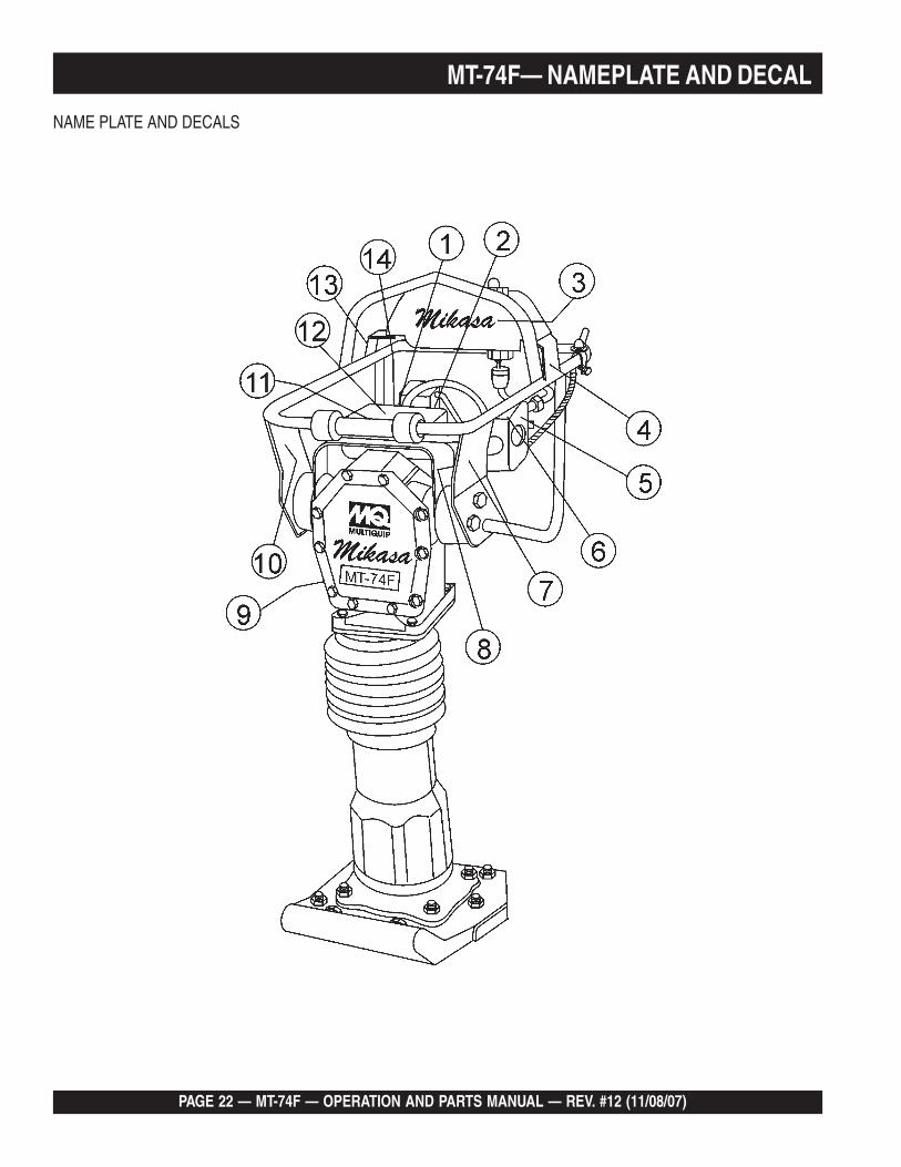
NAME PLATE AND DECALS
MT-74F— NAMEPLATE AND DECAL
MT-74F — OPERATION AND PARTS MANUAL — REV. #12 (11/08/07) — PAGE 23
MT-74F— NAMEPLATE AND DECAL
NAME PLATE AND DECALSNO PART NO PART NAME QTY. REMARKS1 920202930 DECAL: START SWITCH ...................1 ........ NPA-2932 920206020 DECAL: 3400 ~ 3600 RPM 13 920106460 DECAL: MIKASA 14 920206290 DECAL: READ OWNER'S MANUAL 1.......... NPA-6295 1073273308 DECAL: NOTICE .............................. 1 .......... NPA-8316 0732004430 DECAL: START SWITCH 17 0732004450 DECAL: WARNING 18 920203290 DECAL: CAUTION ............................ 1 .......... NPA-3299 PLATE, SERIAL NO. ........................ 1 .......... CONTACT MQ PARTS DEPT. W/ MODEL & S/N10 920107000 DECAL: OIL ..................................... 1 .......... NP-70011 920204370 DECAL: PRE-CLEANER .................. 1 .......... NPA-43712 920206240 DECAL: START/STOP ENGINE ....... 1 .......... NPA-62413 920203330 DECAL: EAR PROTECTION ............ 1 .......... NPA-33314 920203990 DECAL: CLOSE FUEL COCK .......... 1 .......... NPA-399
PAGE 24 — MT-74F — OPERATION AND PARTS MANUAL — REV. #12 (11/08/07)
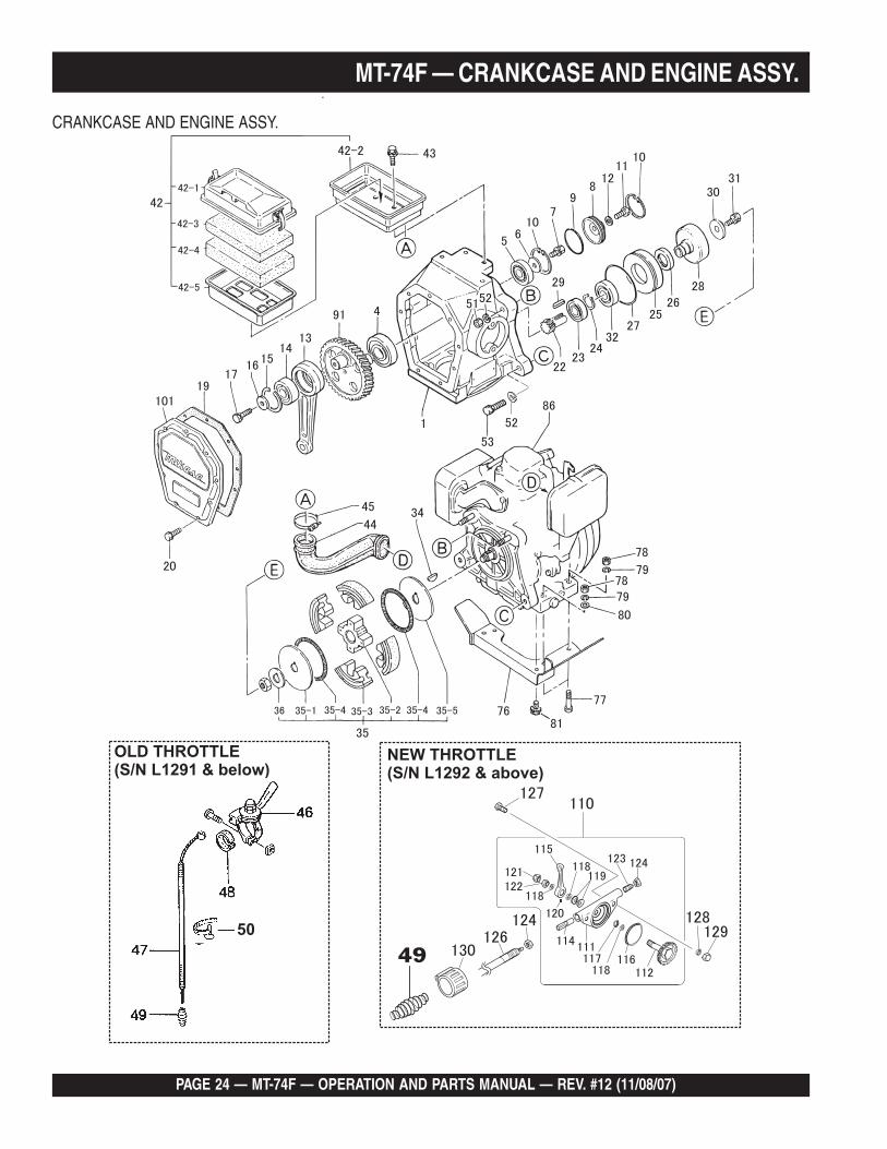
MT-74F — CRANKCASE AND ENGINE ASSY.
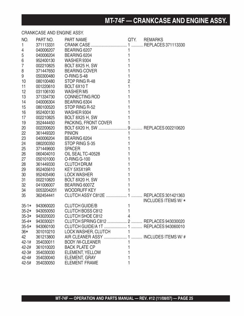
CRANKCASE AND ENGINE ASSY.
MT-74F — OPERATION AND PARTS MANUAL — REV. #12 (11/08/07) — PAGE 25
MT-74F — CRANKCASE AND ENGINE ASSY.
CLUTCH GUIDE / A 145 0053204201 WOODRUFF KEY 146 301010210 LOCK WASHER CLUTCH 147 956300130 THROTTLE LEVER AY 25 1
CRANKCASE AND ENGINE ASSY.NO. PART NO. PART NAME QTY. REMARKS1 371113331 CRANK CASE ................................. 1 ........... REPLACES 3711133304 040006207 BEARING 6207 15 040006204 BEARING 6204 16 952400130 WASHER 9304 17 002210825 BOLT 8X25 H, SW 18 371447650 BEARING COVER 19 050300480 O-RING S-48 110 080100480 STOP RING R-48 211 001220610 BOLT 6X10 T 112 031106100 WASHER M5 113 371334730 CONNECTING ROD 114 040006304 BEARING 6304 115 080100520 STOP RING R-52 116 952400130 WASHER 9304 117 002210825 BOLT 8X25 H, SW 119 352444450 PACKING, FRONT COVER 120 002200620 BOLT 6X20 H, SW .......................... 9 .......... REPLACES 00221062022 361449320 PINION 123 040006204 BEARING 6204 124 080200350 STOP RING S-35 125 371449600 SPACER 126 060404010 OIL SEAL TC-40528 127 050101000 O-RING G-100 128 361449330 CLUTCH DRUM 129 952405610 KEY 5X5X19R 130 952405490 LOCK WASHER 131 002210820 BOLT 8X20 H, SW 132 041006007 BEARING 6007Z 134 0053204201 WOODRUFF KEY 135 362454441 CLUTCH ASSY C812E ................... 1 .......... REPLACES 301421363
INCLUDES ITEMS W/ *35-1* 943060020 CLUTCH GUIDE/B 135-2* 943050050 CLUTCH BOSS C812 135-3* 943020020 CLUTCH SHOE C812 435-4* 943030021 CLUTCH SPRING C812 .................. 2 .......... REPLACES 94303002035-5* 943060100 CLUTCH GUIDE/A 1T ..................... 1 .......... REPLACES 94306001036* 301010210 LOCK WASHER, CLUTCH 142 361213800 AIR CLEANER ASSY ..................... 1 .......... INCLUDES ITEMS W/ #42-1# 354030011 BODY /W-CLEANER 142-2# 361010020 BACK PLATE CP 142-3# 354030030 ELEMENT, YELLOW 142-4# 354030040 ELEMENT, GRAY 142-5# 354030050 ELEMENT FRAME 1

PAGE 26 — MT-74F — OPERATION AND PARTS MANUAL — REV. #12 (11/08/07)
MT-74F — CRANKCASE AND ENGINE ASSY.
MT-74F — OPERATION AND PARTS MANUAL — REV. #12 (11/08/07) — PAGE 27
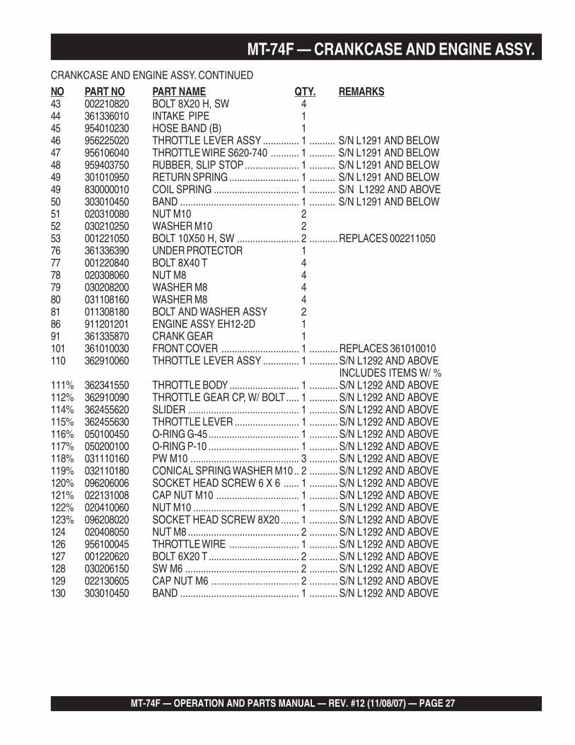
CRANKCASE AND ENGINE ASSY. CONTINUED
NO PART NO PART NAME QTY. REMARKS43 002210820 BOLT 8X20 H, SW 444 361336010 INTAKE PIPE 145 954010230 HOSE BAND (B) 146 956225020 THROTTLE LEVER ASSY .............. 1 .......... S/N L1291 AND BELOW47 956106040 THROTTLE WIRE S620-740 ........... 1 .......... S/N L1291 AND BELOW48 959403750 RUBBER, SLIP STOP ..................... 1 .......... S/N L1291 AND BELOW49 301010950 RETURN SPRING ........................... 1 .......... S/N L1291 AND BELOW49 830000010 COIL SPRING ................................. 1 .......... S/N L1292 AND ABOVE50 303010450 BAND .............................................. 1 .......... S/N L1291 AND BELOW51 020310080 NUT M10 252 030210250 WASHER M10 253 001221050 BOLT 10X50 H, SW ........................ 2 ...........REPLACES 00221105076 361336390 UNDER PROTECTOR 177 001220840 BOLT 8X40 T 478 020308060 NUT M8 479 030208200 WASHER M8 480 031108160 WASHER M8 481 011308180 BOLT AND WASHER ASSY 286 911201201 ENGINE ASSY EH12-2D 191 361335870 CRANK GEAR 1101 361010030 FRONT COVER .............................. 1 ........... REPLACES 361010010110 362910060 THROTTLE LEVER ASSY .............. 1 ........... S/N L1292 AND ABOVE
INCLUDES ITEMS W/ %111% 362341550 THROTTLE BODY ........................... 1 ........... S/N L1292 AND ABOVE112% 362910090 THROTTLE GEAR CP, W/ BOLT..... 1 ........... S/N L1292 AND ABOVE114% 362455620 SLIDER ........................................... 1 ........... S/N L1292 AND ABOVE115% 362455630 THROTTLE LEVER ......................... 1 ........... S/N L1292 AND ABOVE116% 050100450 O-RING G-45 ................................... 1 ........... S/N L1292 AND ABOVE117% 050200100 O-RING P-10 ................................... 1 ........... S/N L1292 AND ABOVE118% 031110160 PW M10 .......................................... 3 ........... S/N L1292 AND ABOVE119% 032110180 CONICAL SPRING WASHER M10.. 2 ........... S/N L1292 AND ABOVE120% 096206006 SOCKET HEAD SCREW 6 X 6 ...... 1 ........... S/N L1292 AND ABOVE121% 022131008 CAP NUT M10 ................................ 1 ........... S/N L1292 AND ABOVE122% 020410060 NUT M10 ......................................... 1 ........... S/N L1292 AND ABOVE123% 096208020 SOCKET HEAD SCREW 8X20 ....... 1 ........... S/N L1292 AND ABOVE124 020408050 NUT M8 ........................................... 2 ........... S/N L1292 AND ABOVE126 956100045 THROTTLE WIRE ........................... 1 ........... S/N L1292 AND ABOVE127 001220620 BOLT 6X20 T ................................... 2 ........... S/N L1292 AND ABOVE128 030206150 SW M6 ............................................ 2 ........... S/N L1292 AND ABOVE129 022130605 CAP NUT M6 .................................. 2 ........... S/N L1292 AND ABOVE130 303010450 BAND .............................................. 1 ........... S/N L1292 AND ABOVE
MT-74F — CRANKCASE AND ENGINE ASSY.
PAGE 28 — MT-74F — OPERATION AND PARTS MANUAL — REV. #12 (11/08/07)
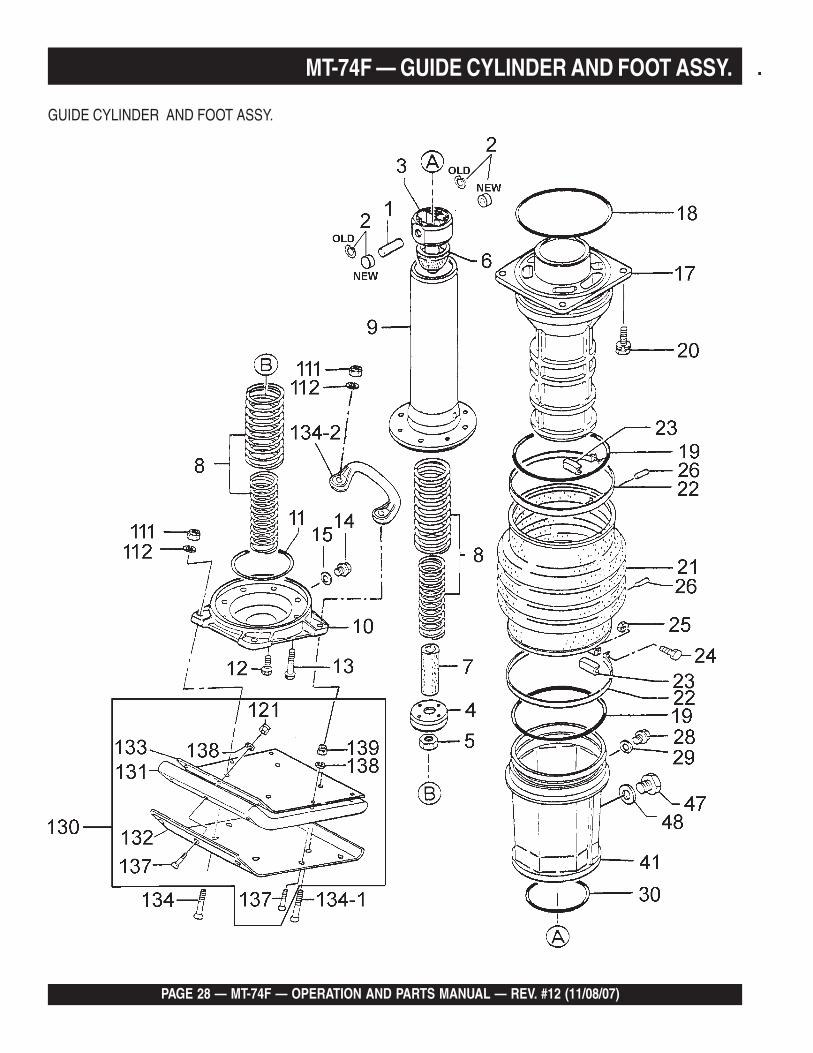
MT-74F — GUIDE CYLINDER AND FOOT ASSY.
GUIDE CYLINDER AND FOOT ASSY.
MT-74F — OPERATION AND PARTS MANUAL — REV. #12 (11/08/07) — PAGE 29
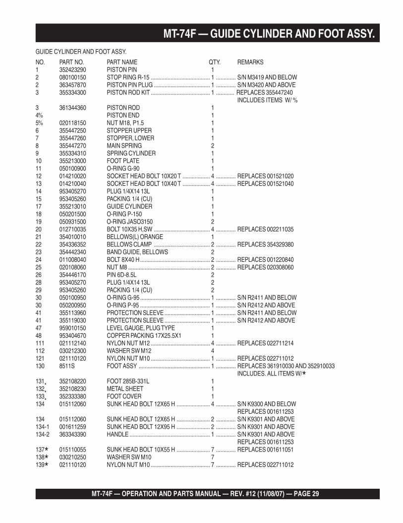
MT-74F — GUIDE CYLINDER AND FOOT ASSY.GUIDE CYLINDER AND FOOT ASSY.
NO. PART NO. PART NAME QTY. REMARKS1 352423290 PISTON PIN 12 080100150 STOP RING R-15 ....................................... 1 ............. S/N M3419 AND BELOW2 363457870 PISTON PIN PLUG ..................................... 1 ............. S/N M3420 AND ABOVE3 355334300 PISTON ROD KIT ....................................... 1 ............ REPLACES 355447240
INCLUDES ITEMS W/ %3 361344360 PISTON ROD 14% PISTON END 15% 020118150 NUT M18, P1.5 16 355447250 STOPPER UPPER 17 355447260 STOPPER, LOWER 18 355447270 MAIN SPRING 29 355334310 SPRING CYLINDER 110 355213000 FOOT PLATE 111 050100900 O-RING G-90 112 014210020 SOCKET HEAD BOLT 10X20 T .................. 4 ............. REPLACES 00152102013 014210040 SOCKET HEAD BOLT 10X40 T .................. 4 ............. REPLACES 00152104014 953405270 PLUG 1/4X14 13L 115 953405260 PACKING 1/4 (CU) 117 355213010 GUIDE CYLINDER 118 050201500 O-RING P-150 119 050931500 O-RING JASO3150 220 012710035 BOLT 10X35 H,SW ..................................... 4 ............. REPLACES 00221103521 354010010 BELLOWS(L) ORANGE 122 354336352 BELLOWS CLAMP ..................................... 2 ............. REPLACES 35432938023 354442340 BAND GUIDE, BELLOWS 224 011008040 BOLT 8X40 H .............................................. 2 ............. REPLACES 00122084025 020108060 NUT M8 ...................................................... 2 ............. REPLACES 02030806026 354446170 PIN 6D-8.5L 228 953405270 PLUG 1/4X14 13L 229 953405260 PACKING 1/4 (CU) 230 050100950 O-RING G-95 .............................................. 1 ............. S/N R2411 AND BELOW30 050200950 O-RING P-95 .............................................. 1 ............. S/N R2412 AND ABOVE41 355113960 PROTECTION SLEEVE .............................. 1 ............. S/N R2411 AND BELOW41 355119030 PROTECTION SLEEVE .............................. 1 ............. S/N R2412 AND ABOVE47 959010150 LEVEL GAUGE, PLUG TYPE 148 953404670 COPPER PACKING 17X25.5X1 1111 021112140 NYLON NUT M12 ....................................... 4 ............. REPLACES 022711214112 030212300 WASHER SW M12 4121 021110120 NYLON NUT M10 ....................................... 1 ............. REPLACES 022711012130 8511S FOOT ASSY ............................................... 1 ............. REPLACES 361910030 AND 352910033
INCLUDES. ALL ITEMS W/*131*
352108220 FOOT 285B-331L 1132
*352108230 METAL SHEET 1
133*
352333380 FOOT COVER 1134 015112060 SUNK HEAD BOLT 12X65 H ...................... 4 ............. S/N K9300 AND BELOW
REPLACES 001611253134 015112060 SUNK HEAD BOLT 12X65 H ...................... 2 ............. S/N K9301 AND ABOVE134-1 001611259 SUNK HEAD BOLT 12X95 H ...................... 2 ............. S/N K9301 AND ABOVE134-2 363343390 HANDLE ..................................................... 1 ............. S/N K9301 AND ABOVE
REPLACES 001611253137* 015110055 SUNK HEAD BOLT 10X55 H ...................... 7 ............. REPLACES 001611051138* 030210250 WASHER SW M10 7139* 021110120 NYLON NUT M10 ....................................... 7 ............. REPLACES 022711012
PAGE 30 — MT-74F — OPERATION AND PARTS MANUAL — REV. #12 (11/08/07)
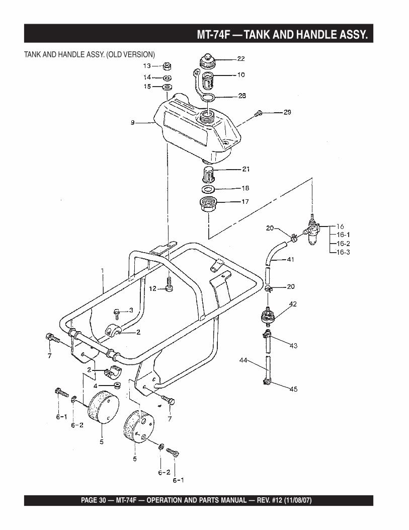
MT-74F — TANK AND HANDLE ASSY.
TANK AND HANDLE ASSY. (OLD VERSION)
MT-74F — OPERATION AND PARTS MANUAL — REV. #12 (11/08/07) — PAGE 31
TANK AND HANDLE ASSY. (OLD VERSION)NO PART NO PART NAME QTY. REMARKS1 361117410 HANDLE .................................................. 1 ............... REPLACES 361113920
S/N L1291 AND BELOW2 361449430 ROLLER HANDLE 23 001710525 FLANGE BOLT 5X25 H 44 022610505 FLANGE NUT 45 351319900 SHOCK ABSORBER 26-1 014210020 SOCKET HEAD BOLT 10X20T ............... 4 ................REPLACES 0015210206-2 033121009 TOOTH LOCKED WASHER BM10 47 012210020 BOLT 10X20 H, SW ................................ 4 ................REPLACES 0022110209 355113610 FUEL TANK 110 954404890 FILTER,TANK .......................................... 1 ................S/N M2534 AND BELOW12 011208030 BOLT 8X30 T ........................................... 2 ................REPLACES 00122083013 022710809 NYLON NUT M8 214 030208200 WASHER, SW M8 215 952401450 WASHER 8.5X22X3 ................................ 2 ................REPLACES 95340564016 954300390 FUEL COCK ASSY ................................. 1 ................S/N L1291 AND BELOW
INCLUDES ALL ITEMS W/*16-1* 0642001410 CUP, FUEL COCK 116-2* 0642001420 SCREEN, FUEL COCK 116-3* 0642001430 RUBBER PACKING, FUEL COCK 117 351437785 HOLDER, FUEL COCK 118 351439290 PACKING, COCK FUEL, COCK HOLDER .... 1 ................REPLACES 95340564020 954404590 HOSE BAND 9.5D 221 954405080 STRAINER 122 361910020 CAP ASSY, TANK 128 353449010 STRAP, FUEL TANK CAP 129 009110014 SCREW, PAN HEAD 8X10 241 352423730 HOSE, FUEL 142 301419750 FILTER, IN-LINE 143 301420730 HOSE BAND ........................................... 2 ................REPLACES 95440303044 351435160 FUEL HOSE B-95 145 954404590 HOSE BAND 9.5D 2
MT-74F — TANK AND HANDLE ASSY.
PAGE 32 — MT-74F — OPERATION AND PARTS MANUAL — REV. #12 (11/08/07)
MT-74F — TANK AND HANDLE ASSY.
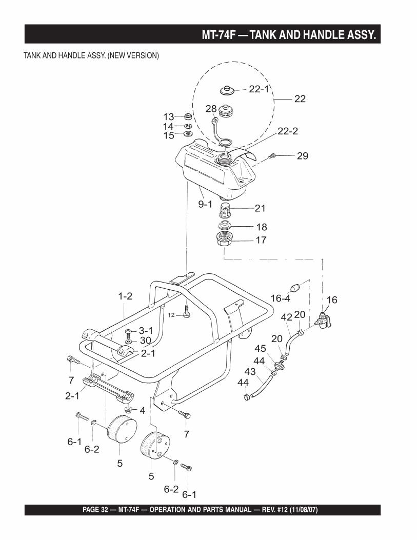
TANK AND HANDLE ASSY. (NEW VERSION)
MT-74F — OPERATION AND PARTS MANUAL — REV. #12 (11/08/07) — PAGE 33
MT-74F — TANK AND HANDLE ASSY.TANK AND HANDLE ASSY. (NEW VERSION)NO PART NO PART NAME QTY. REMARKS1 361117750 HANDLE .................................................. 1 ................S/N L1292 AND ABOVE2-1 955200052 ROLLER, W/ PIN, SET 13-1 091005025 SCREW 5X25 44 022610505 FLANGE NUT 45 351319900 SHOCK ABSORBER 26-1 014210020 SOCKET HEAD BOLT 10X20T ............... 4 ................REPLACES 0015210206-2 033121009 TOOTH LOCKED WASHER BM10 47 012210020 BOLT 10X20 H, SW ................................ 4 ................REPLACES 0022110209-1 361116910 FUEL TANK 112 011208030 BOLT 8X30 T ........................................... 2 ................REPLACES 00122083013 022710809 NYLON NUT M8 214 030208200 WASHER, SW M8 215 952401450 WASHER 8.5X22X3 ................................ 2 ................REPLACES 95340564016 954300720 FUEL COCK ASSY ................................. 1 ................S/N L1292 AND ABOVE16-4 353432250 CAP 117 351437785 HOLDER, FUEL COCK 118 954406020 PACKING, FUEL TANK ........................... 1 ................S/N M2535 AND ABOVE20 954406420 HOSE BAND 10.5 221 954406010 STRAINER 122 361910070 CAP ASSY, TANK ................................... 1 ................S/N M2535 AND ABOVE
INCLUDES ITEMS W/ *22-1* 361455740 SUB CAP 1 S/N M2535 AND ABOVE22-2 920208960 TAG, GASOLINE 1 S/N M2535 AND ABOVE28* 353449010 STRAP, FUEL TANK CAP 129 009110014 SCREW, PAN HEAD 8X10 230 031105080 PW M5 442 351435160 FUEL HOSE B-95 143 351436350 FUEL HOSE R-150L D8 144 301420730 HOSE BAND ........................................... 2 ................. REPLACES 95440303045 301419750 FUEL FILTER CP, MQ75MIC. 1
PAGE 34 — MT-74F — OPERATION AND PARTS MANUAL — REV. #12 (11/08/07)
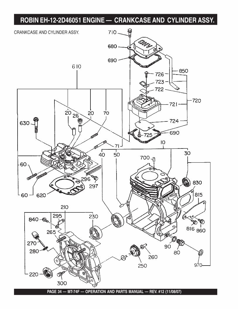
ROBIN EH-12-2D46051 ENGINE — CRANKCASE AND CYLINDER ASSY.
CRANKCASE AND CYLINDER ASSY.
MT-74F — OPERATION AND PARTS MANUAL — REV. #12 (11/08/07) — PAGE 35
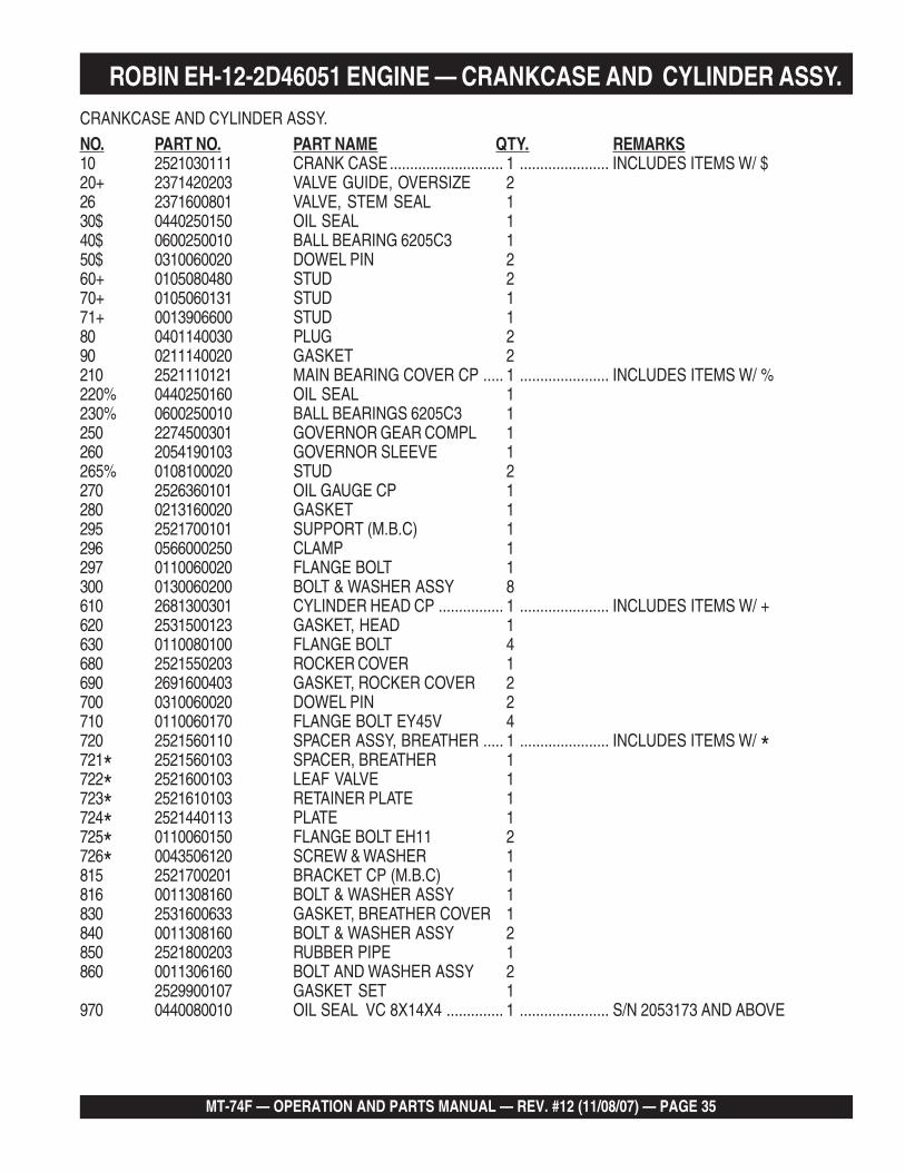
ROBIN EH-12-2D46051 ENGINE — CRANKCASE AND CYLINDER ASSY.CRANKCASE AND CYLINDER ASSY.
NO. PART NO. PART NAME QTY. REMARKS10 2521030111 CRANK CASE............................ 1 ...................... INCLUDES ITEMS W/ $20+ 2371420203 VALVE GUIDE, OVERSIZE 226 2371600801 VALVE, STEM SEAL 130$ 0440250150 OIL SEAL 140$ 0600250010 BALL BEARING 6205C3 150$ 0310060020 DOWEL PIN 260+ 0105080480 STUD 270+ 0105060131 STUD 171+ 0013906600 STUD 180 0401140030 PLUG 290 0211140020 GASKET 2210 2521110121 MAIN BEARING COVER CP ..... 1 ...................... INCLUDES ITEMS W/ %220% 0440250160 OIL SEAL 1230% 0600250010 BALL BEARINGS 6205C3 1250 2274500301 GOVERNOR GEAR COMPL 1260 2054190103 GOVERNOR SLEEVE 1265% 0108100020 STUD 2270 2526360101 OIL GAUGE CP 1280 0213160020 GASKET 1295 2521700101 SUPPORT (M.B.C) 1296 0566000250 CLAMP 1297 0110060020 FLANGE BOLT 1300 0130060200 BOLT & WASHER ASSY 8610 2681300301 CYLINDER HEAD CP ................ 1 ...................... INCLUDES ITEMS W/ +620 2531500123 GASKET, HEAD 1630 0110080100 FLANGE BOLT 4680 2521550203 ROCKER COVER 1690 2691600403 GASKET, ROCKER COVER 2700 0310060020 DOWEL PIN 2710 0110060170 FLANGE BOLT EY45V 4720 2521560110 SPACER ASSY, BREATHER ..... 1 ...................... INCLUDES ITEMS W/ *721* 2521560103 SPACER, BREATHER 1722* 2521600103 LEAF VALVE 1723* 2521610103 RETAINER PLATE 1724* 2521440113 PLATE 1725* 0110060150 FLANGE BOLT EH11 2726* 0043506120 SCREW & WASHER 1815 2521700201 BRACKET CP (M.B.C) 1816 0011308160 BOLT & WASHER ASSY 1830 2531600633 GASKET, BREATHER COVER 1840 0011308160 BOLT & WASHER ASSY 2850 2521800203 RUBBER PIPE 1860 0011306160 BOLT AND WASHER ASSY 2
2529900107 GASKET SET 1970 0440080010 OIL SEAL VC 8X14X4 .............. 1 ...................... S/N 2053173 AND ABOVE
PAGE 36 — MT-74F — OPERATION AND PARTS MANUAL — REV. #12 (11/08/07)
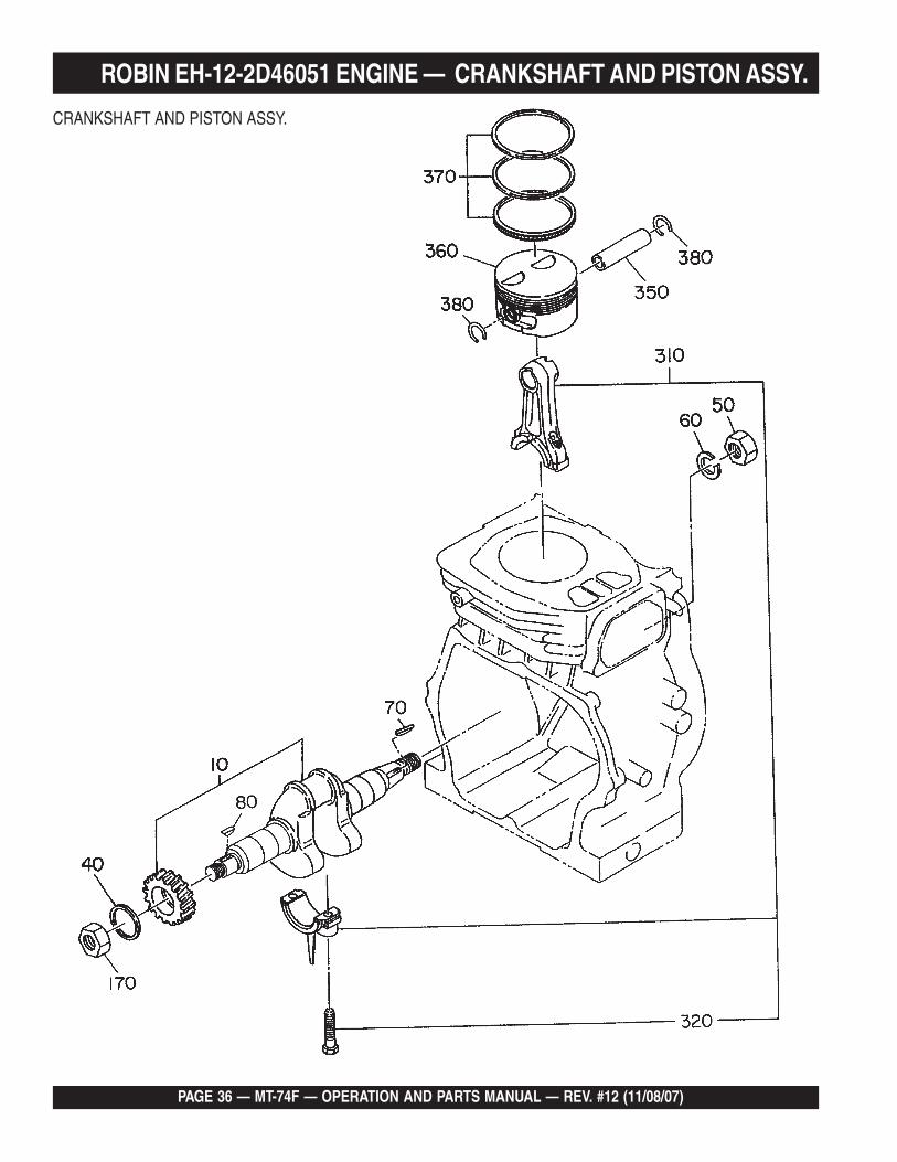
CRANKSHAFT AND PISTON ASSY.
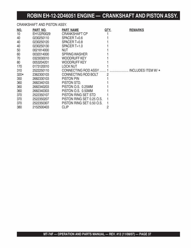
ROBIN EH-12-2D46051 ENGINE — CRANKSHAFT AND PISTON ASSY.
MT-74F — EH12-2D ROBIN ENGINE— CRANKSHAFT AND PISTON
MT-74F — OPERATION AND PARTS MANUAL — REV. #12 (11/08/07) — PAGE 37
CRANKSHAFT AND PISTON ASSY.NO. PART NO. PART NAME QTY. REMARKS10 EH122R0029 CRANKSHAFT CP 140 0230250110 SPACER T=0.6 140 0230250120 SPACER T=0.8 140 0230250130 SPACER T=1.0 150 0021814000 NUT 160 0032014000 SPRING WASHER 170 0323030010 WOODRUFF KEY 180 0053204201 WOODRUFF KEY 1170 0173120010 LOCK NUT 1310 2522250110 CONNECTING ROD ASSY ........ 1 ...................... INCLUDES ITEM W/ *320* 2362300103 CONNECTING ROD BOLT 2350 2682330103 PISTON PIN 1360 2682340103 PISTON STD. 1360 2682340203 PISTON O.S. 0.25MM 1360 2682340303 PISTON O.S. 0.50MM 1370 2522350107 PISTON RING SET STD 1370 2522350207 PISTON RING SET 0.25 O.S. 1370 2522350307 PISTON RING SET 0.50 O.S. 1380 2152500403 CLIP 2
ROBIN EH-12-2D46051 ENGINE — CRANKSHAFT AND PISTON ASSY.
— E— CRANKSHAFT AND PISTON
PAGE 38 — MT-74F — OPERATION AND PARTS MANUAL — REV. #12 (11/08/07)
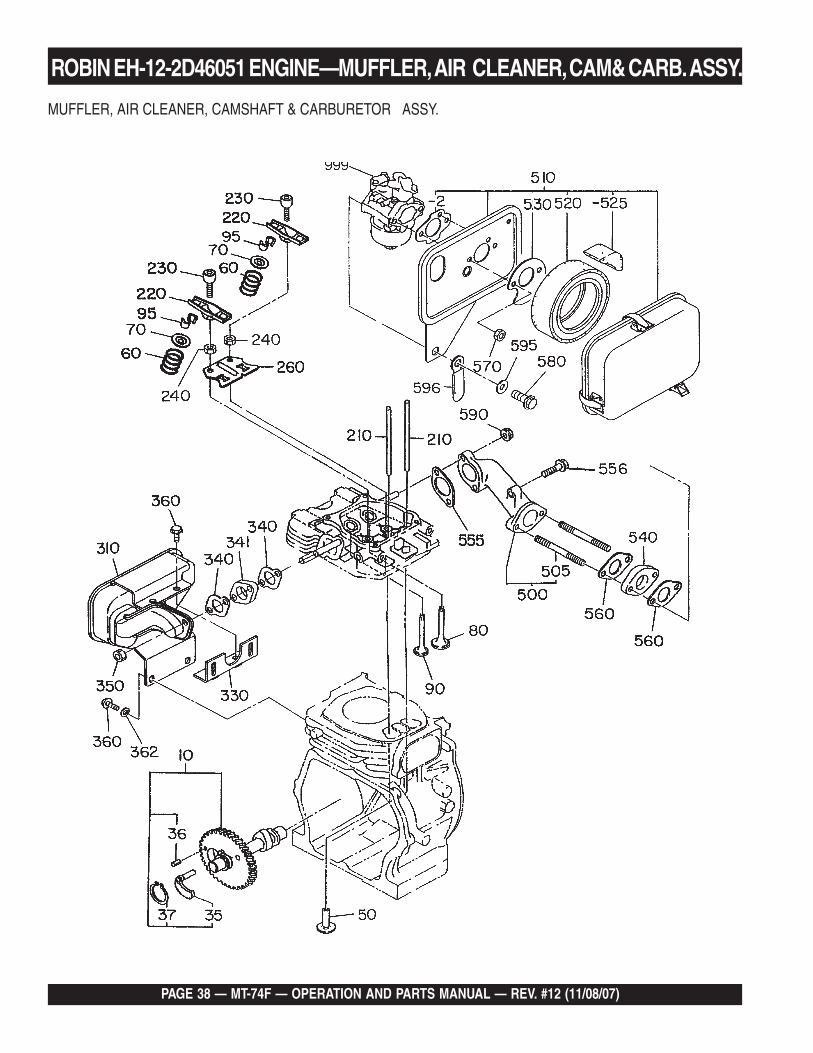
MUFFLER, AIR CLEANER, CAMSHAFT & CARBURETOR ASSY.
ROBIN EH-12-2D46051 ENGINE—MUFFLER, AIR CLEANER, CAM& CARB. ASSY.
MT-74F — OPERATION AND PARTS MANUAL — REV. #12 (11/08/07) — PAGE 39
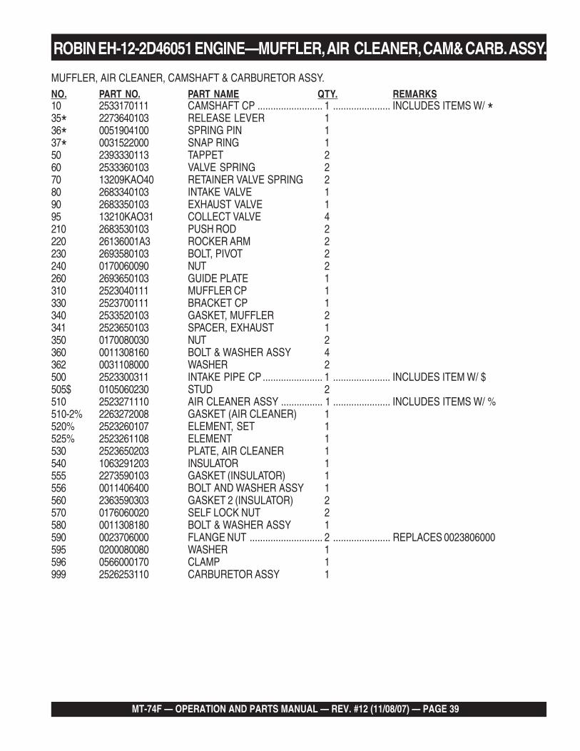
MUFFLER, AIR CLEANER, CAMSHAFT & CARBURETOR ASSY.NO. PART NO. PART NAME QTY. REMARKS10 2533170111 CAMSHAFT CP ......................... 1 ...................... INCLUDES ITEMS W/ *35* 2273640103 RELEASE LEVER 136* 0051904100 SPRING PIN 137* 0031522000 SNAP RING 150 2393330113 TAPPET 260 2533360103 VALVE SPRING 270 13209KAO40 RETAINER VALVE SPRING 280 2683340103 INTAKE VALVE 190 2683350103 EXHAUST VALVE 195 13210KAO31 COLLECT VALVE 4210 2683530103 PUSH ROD 2220 26136001A3 ROCKER ARM 2230 2693580103 BOLT, PIVOT 2240 0170060090 NUT 2260 2693650103 GUIDE PLATE 1310 2523040111 MUFFLER CP 1330 2523700111 BRACKET CP 1340 2533520103 GASKET, MUFFLER 2341 2523650103 SPACER, EXHAUST 1350 0170080030 NUT 2360 0011308160 BOLT & WASHER ASSY 4362 0031108000 WASHER 2500 2523300311 INTAKE PIPE CP ....................... 1 ...................... INCLUDES ITEM W/ $505$ 0105060230 STUD 2510 2523271110 AIR CLEANER ASSY ................ 1 ...................... INCLUDES ITEMS W/ %510-2% 2263272008 GASKET (AIR CLEANER) 1520% 2523260107 ELEMENT, SET 1525% 2523261108 ELEMENT 1530 2523650203 PLATE, AIR CLEANER 1540 1063291203 INSULATOR 1555 2273590103 GASKET (INSULATOR) 1556 0011406400 BOLT AND WASHER ASSY 1560 2363590303 GASKET 2 (INSULATOR) 2570 0176060020 SELF LOCK NUT 2580 0011308180 BOLT & WASHER ASSY 1590 0023706000 FLANGE NUT ............................ 2 ...................... REPLACES 0023806000595 0200080080 WASHER 1596 0566000170 CLAMP 1999 2526253110 CARBURETOR ASSY 1
ROBIN EH-12-2D46051 ENGINE—MUFFLER, AIR CLEANER, CAM& CARB. ASSY.
PAGE 40 — MT-74F — OPERATION AND PARTS MANUAL — REV. #12 (11/08/07)
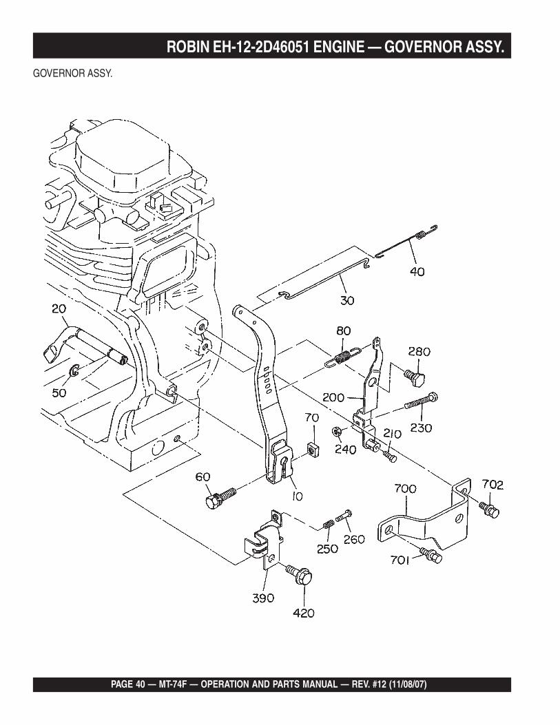
GOVERNOR ASSY.
ROBIN EH-12-2D46051 ENGINE — GOVERNOR ASSY.
MT-74F — OPERATION AND PARTS MANUAL — REV. #12 (11/08/07) — PAGE 41
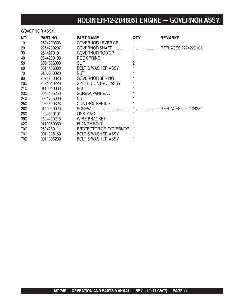
GOVERNOR ASSY.
NO. PART NO. PART NAME QTY. REMARKS10 2524230303 GOVERNOR LEVER CP 120 2264230207 GOVERNOR SHAFT .................. 1 ...................... REPLACES 227422010330 2544270101 GOVERNOR ROD CP 140 2544280103 ROD SPRING 150 0031306000 CLIP 260 0011406300 BOLT & WASHER ASSY 170 0186060020 NUT 180 2524250323 GOVERNOR SPRING 1200 2524340220 SPEED CONTROL ASSY 1210 0116040030 BOLT 1230 0043105250 SCREW, PANHEAD 1240 0021705000 NUT 1250 2054600323 CONTROL SPRING 1260 0140040020 SCREW ...................................... 1 ...................... REPLACES 0043104250280 2264310101 LINK PIVOT 1390 2524420213 WIRE BRACKET 1420 0110060030 FLANGE BOLT 1700 2524280111 PROTECTOR CP, GOVERNOR 1701 0011308160 BOLT & WASHER ASSY 1702 0011306200 BOLT & WASHER ASSY 1
ROBIN EH-12-2D46051 ENGINE — GOVERNOR ASSY.
PAGE 42 — MT-74F — OPERATION AND PARTS MANUAL — REV. #12 (11/08/07)
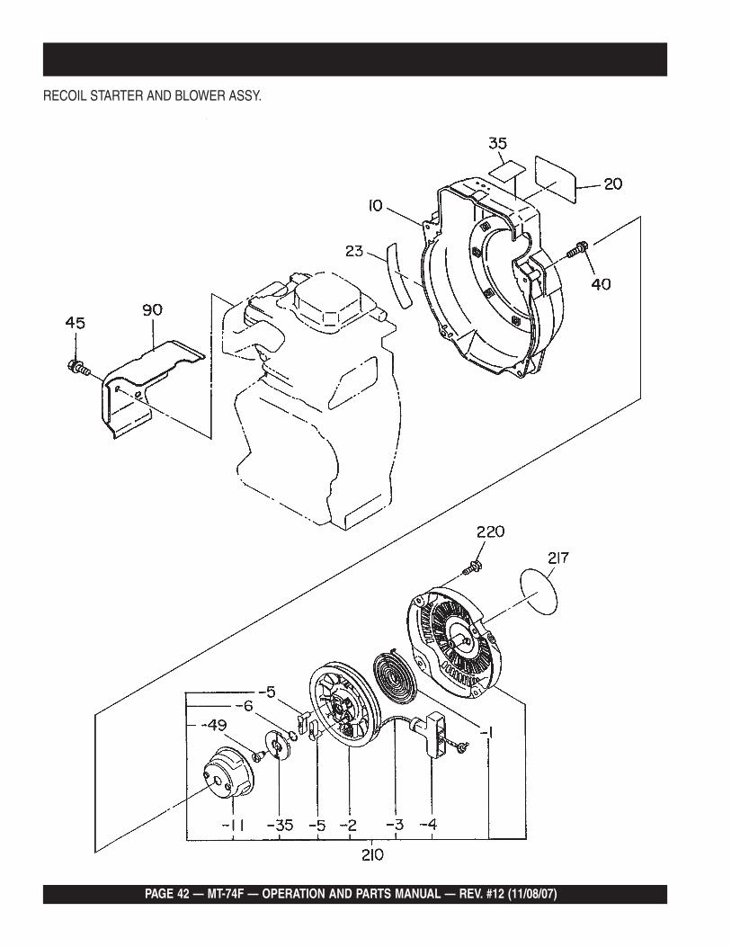
RECOIL STARTER AND BLOWER ASSY.
MT-74F — OPERATION AND PARTS MANUAL — REV. #12 (11/08/07) — PAGE 43
ROBIN EH-12-2D46051 ENGINE —RECOIL STARTER AND BLOWER ASSY.
RECOIL STARTER AND BLOWER ASSY.
NO. PART NO. PART NAME QTY. REMARKS10 2525165211 BLOWER HOUSING CP 2 120 2069170103 LABEL, MIKASA MARK 123 2689520203 LABEL, EMISSION CONTROL 135 2689180203 LABEL, ENGINE NAME 140 0011406550 BOLT & WASHER ASSY 445 0110060140 FLANGE BOLT 290 2525270213 HEAD COVER 1210 2685020100 RECOIL STARTER ASSY.......... 1 ...................... INCLUDES ITEMS W/*210-1* 2705011508 SPIRAL SPRING 1210-2* 2695012008 REEL 1210-3* 2695011008 STARTER ROPE 1210-4* 2615010008 STARTER KNOB 1210-5* 2705012508 RATCHET 2210-6* 2275013108 FRICTION SPRING 1210-11* 2685014508 STARTER PULLEY 1210-35* 2705026108 RATCHET GUIDE 1210-49* 2275015208 SET SCREW 1217 2069170103 LABEL, TRADEMARK 1220 0110060050 FLANGE BOLT .......................... 4 ...................... REPLACES 0110060010
PAGE 44 — MT-74F — OPERATION AND PARTS MANUAL — REV. #12 (11/08/07)
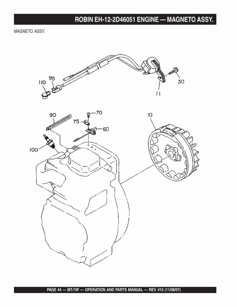
ROBIN EH-12-2D46051 ENGINE — MAGNETO ASSY.
MAGNETO ASSY.
MT-74F — OPERATION AND PARTS MANUAL — REV. #12 (11/08/07) — PAGE 45
MAGNETO ASSY.NO PART NO PART NAME QTY. REMARKS10 2527933101 FLYWHEEL CP 111 2697943001 IGNITION COIL CP 130 0011406250 BOLT & WASHER ASSY 260 0660000371 STOP SWITCH ASSY (ON-OFF)170 0150040090 TAPPING SCREW 275 0566030010 CLAMP 190 0566000250 CLAMP 195 0659000010 SPARK PLUG CLIP ................... 1 ...................... REPLACES 0655000100100 0650140580 SPARK PLUG, BR6ES .............. 1 ...................... REPLACES 0650140100110 2307510113 SPARK PLUG CAP 1
ROBIN EH-12-2D46051 ENGINE — MAGNETO ASSY.
PAGE 46 — MT-74F — OPERATION AND PARTS MANUAL — REV. #12 (11/08/07)
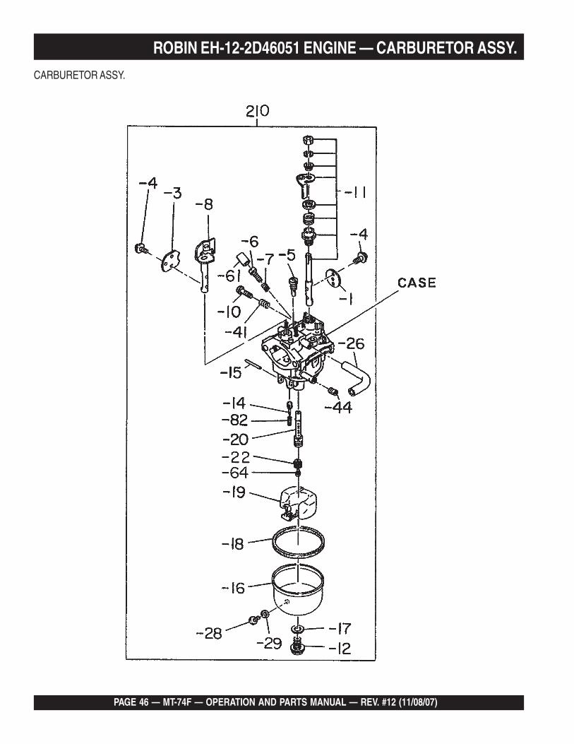
ROBIN EH-12-2D46051 ENGINE — CARBURETOR ASSY.
CARBURETOR ASSY.
MT-74F — OPERATION AND PARTS MANUAL — REV. #12 (11/08/07) — PAGE 47
ROBIN EH-12-2D46051 ENGINE — CARBURETOR ASSY.CARBURETOR ASSY.NO PART NO PART NAME QTY. REMARKS210 2526253120 CARBURETOR ASSY. ............... 1 ...................... INCLUDES ITEMS W/ *210-1* 2526253508 THROTTLE VALVE 1210-3* 2366252808 CHOKE VALVE 1210-4* 2376245108 SCREW 4210-5* 2166230308 PILOT JET 1210-6* 2376243508 PILOT SCREW 1210-7* 2306244608 SPRING 1210-8* 2526252108 CHOKE SHAFT 1210-10* 2466243508 ADJUST SCREW 1210-11* 1616253008 THROTTLE SHAFT 1210-12* 2366245108 BOLT 1210-14* 1616235208 NEEDLE 1210-15* 2146251508 PIN 1210-16* 2366255208 FLOAT CHAMBER BODY 1210-17* 2366245008 PACKING 1210-18* 2366254008 PACKING, CHAMBER 1210-19* 2366250508 FLOAT 1210-20* 2526244008 MAIN NOZZLE 1210-22* 2356242508 GUIDE HOLDER 1210-26* 1616235308 HOSE 1210-28* 2366235008 SCREW 1210-29* 2366254108 PACKING 1210-41* 2096244508 SPRING 1210-44* 1616240008 GUIDE HOLDER 1210-61* 2466255108 CAP 1210-64* 2356242508 MAIN JET 1210-82* 2366244508 SPRING 1
PAGE 48 — MT-74F — OPERATION AND PARTS MANUAL — REV. #12 (11/08/07)
PAYMENT TERMS
Terms of payment for parts are net 30 days.
FREIGHT POLICY
All parts orders will be shipped collect orprepaid with the charges added to the invoice.All shipments are F.O.B. point of origin.Multiquip’s responsibility ceases when a signedmanifest has been obtained from the carrier,and any claim for shortage or damage must besettled between the consignee and the carrier.
MINIMUM ORDER
The minimum charge for orders from Multiquipis $15.00 net. Customers will be asked forinstructions regarding handling of orders notmeeting this requirement.
RETURNED GOODS POLICY
Return shipments will be accepted and creditwill be allowed, subject to the following provi-sions:
1. A Returned Material Authorization mustbe approved by Multiquip prior to ship-ment.
2. To obtain a Return Material Authorization,a list must be provided to Multiquip PartsSales that defines item numbers, quanti-ties, and descriptions of the items to bereturned.
a. The parts numbers and descriptionsmust match the current parts pricelist.
b. The list must be typed or computergenerated.
c. The list must state the reason(s) forthe return.
d. The list must reference the salesorder(s) or invoice(s) under which theitems were originally purchased.
e. The list must include the name andphone number of the person request-ing the RMA.
3. A copy of the Return Material Authoriza-tion must accompany the return shipment.
4. Freight is at the sender’s expense. Allparts must be returned freight prepaid toMultiquip’s designated receiving point.
5. Parts must be in new and resalable con-dition, in the original Multiquip package (ifany), and with Multiquip part numbersclearly marked.
6. The following items are not returnable:
a. Obsolete parts. (If an item is in theprice book and shows as being re-placed by another item, it is obsolete.)
b. Any parts with a limited shelf life(such as gaskets, seals, “O” rings,and other rubber parts) that were pur-chased more than six months prior tothe return date.
c. Any line item with an extended dealernet price of less than $5.00.
d. Special order items.
e. Electrical components.
f. Paint, chemicals, and lubricants.
g. Decals and paper products.
h. Items purchased in kits.
7. The sender will be notified of any materialreceived that is not acceptable.
8. Such material will be held for five workingdays from notification, pending instruc-tions. If a reply is not received within fivedays, the material will be returned to thesender at his expense.
9. Credit on returned parts will be issued atdealer net price at time of the originalpurchase, less a 15% restocking charge.
10. In cases where an item is accepted, forwhich the original purchase documentcan not be determined, the price will bebased on the list price that was effectivetwelve months prior to the RMA date.
11. Credit issued will be applied to futurepurchases only.
PRICING AND REBATES
Prices are subject to change without priornotice. Price changes are effective on a spe-cific date and all orders received on or after thatdate will be billed at the revised price. Rebatesfor price declines and added charges for priceincreases will not be made for stock on handat the time of any price change.
Multiquip reserves the right to quote and selldirect to Government agencies, and to OriginalEquipment Manufacturer accounts who useour products as integral parts of their ownproducts.
SPECIAL EXPEDITING SERVICE
A $35.00 surcharge will be added to the invoicefor special handling including bus shipments,insured parcel post or in cases where Multiquipmust personally deliver the parts to the carrier.
LIMITATIONS OF SELLER’S LIABILITY
Multiquip shall not be liable hereunder fordamages in excess of the purchase price of theitem with respect to which damages areclaimed, and in no event shall Multiquip beliable for loss of profit or good will or for anyother special, consequential or incidental dam-ages.
LIMITATION OF WARRANTIES
No warranties, express or implied, are madein connection with the sale of parts or tradeaccessories nor as to any engine not manufac-tured by Multiquip. Such warranties made inconnection with the sale of new, complete unitsare made exclusively by a statement of war-ranty packaged with such units, and Multiquipneither assumes nor authorizes any person toassume for it any other obligation or liabilitywhatever in connection with the sale of itsproducts. Apart from such written statement ofwarranty, there are no warranties, express,implied or statutory, which extend beyond thedescription of the products on the face hereof.
Effective: February 22, 2006
TERMS AND CONDITIONS OF SALE — PARTS
MT-74F — OPERATION AND PARTS MANUAL — REV. #12 (11/08/07) — PAGE 49
NOTE PAGE
OPERATION AND PARTS MANUAL
Your Local Dealer is:
HERE’S HOW TO GET HELPPLEASE HAVE THE MODEL AND SERIAL
NUMBER ON-HAND WHEN CALLING
© COPYRIGHT 2007, MULTIQUIP INC.
Multiquip Inc, the MQ logo and the Mikasa logo are registered trademarks of Multiquip Inc. and may not be used, reproduced, or altered without written permission. All othertrademarks are the property of their respective owners and used with permission.
This manual MUST accompany the equipment at all times. This manual is considered a permanent part of the equipment and should remain with the unit if resold.
The information and specifications included in this publication were in effect at the time of approval for printing. Illustrations, descriptions, references and technical datacontained in this manual are for guidance only and may not be considered as binding. Multiquip Inc. reserves the right to discontinue or change specifications, design orthe information published in this publication at any time without notice and without incurring any obligations.
UNITED STATESMultiquip Corporate Office MQ Parts Department18910 Wilmington Ave. Tel. (800) 421-1244 800-427-1244 Fax: 800-672-7877Carson, CA 90746 Fax (800) 537-3927 310-537-3700 Fax: 310-637-3284Contact: [email protected] Parts Warranty Department800-306-2926 Fax: 800-672-7877 800-421-1244, Ext. 279 Fax: 310-537-1173310-537-3700 Fax: 310-637-3284 310-537-3700, Ext. 279Service Department Technial Assistance800-421-1244 Fax: 310-537-4259 800-478-1244 Fax: 310-631-5032310-537-3700
MEXICO UNITED KINGDOMMQ Cipsa Multiquip (UK) Limited Head OfficeCarr. Fed. Mexico-Puebla KM 126.5 Tel: (52) 222-225-9900 Hanover Mill, Fitzroy Street, Tel: 0161 339 2223Momoxpan, Cholula, Puebla 72760 Mexico Fax: (52) 222-285-0420 Ashton-under-Lyne, Fax: 0161 339 3226Contact: [email protected] Lancashire OL7 0TL
Contact: [email protected]
CANADA BRAZILMultiquip Multiquip4110 Industriel Boul. Tel: (450) 625-2244 Av. Evandro Lins e Silva, 840 - grupo 505 Tel: 011-55-21-3433-9055Laval, Quebec, Canada H7L 6V3 Fax: (450) 625-8664 Barra de Tijuca - Rio de Janeiro Fax: 011-55-21-3433-9055Contact: [email protected] Contact: [email protected], [email protected]